Wells Regulation – New Construction of the Hole, Casing, Well Screen and Annular Space (technical bulletin)
The purpose of this technical bulletin is to summarize the information on new well construction found in the Water Supply Wells – Requirements and Best Management Practices manual published by the Ministry of the Environment, December 2009. This technical bulletin is one in a series of 11 on well issues created for a person who is considering a new water supply well or who currently owns a water supply well.
April 2011
This technical bulletin provides some construction steps that must be undertaken and materials that must be used to meet the requirements of Regulation 903 (Wells Regulation), as amended, made under the Ontario Water Resources Act. Additional information on new well construction is provided in the Wells Regulation – Completing the New Well’s Structure technical bulletin.
Common Types of Wells
Water supply wells can have a:
- narrow diameter (e.g. driven/jetted point wells)
- medium diameter (e.g. drilled wells), or
- large diameter (e.g. bored and dug wells).
Drilled wells tend to be constructed to deeper depths when compared to dug and driven/jetted point wells. Figures 1 to 7, located at the end of this technical bulletin, show common types of wells.
Wells are completed into water-bearing overburden formations such as sand or gravel or bedrock formations such as limestone or granite.
Further information on well types and construction methods can be found in Chapter 5: Constructing and Casing the Well in the Water Supply Wells – Requirements and Best Management Practices manual.
Location of the Aquifer – Shallow or Deep
An aquifer is a water–bearing formation that is able to transmit water in sufficient quantities to serve as a source of a water supply. It may be feasible to use a backhoe or a boring rig to construct a large diameter well in a shallow aquifer. Aquifers located in bedrock formations, however, typically require specialized drilling equipment designed to handle this hard material.
The Wells Regulation requires that a new water supply well be at least 6 metres (19.7 feet) deep unless the only useful aquifer necessitates a shallower well. In no case is the water supply well allowed to be less than 3 metres (10 feet) deep.
Casing and Well Screen for a New Well
A water supply well has casing and may also have a well screen.
A casing means pipe, tubing or other material installed in a well to support its sides, but does not include a well screen. Casing keeps the hole open, prevents overburden materials from entering the well and accommodates pumping equipment. Casing may also be used to seal off unwanted formations.
Under the Wells Regulation, casing for new water supply wells can be made of steel, stainless steel, galvanized steel, concrete, plastic or fibreglass. Making the casing choice that is best for the specific situation involves consideration of the geologic formation, the production capacity of the aquifer, the water uses planned for the well, the size of the hole and many other factors.
Well screen means a perforated pipe or tubing, unsealed concrete tiles or other material installed in a well to filter out particulate matter and forms the water intake zone.
To prevent water-bearing formation collapse into the well and reduce sediment or particles in the well water, a well screen should be installed in most overburden formations and sometimes in bedrock. A well screen is typically not necessary in bedrock formations as the bedrock is strong enough to keep the hole open after the hole has been constructed.
The person constructing the well is required to meet the following Wells Regulation requirements for casing and well screen when constructing a new water supply well.
For new wells, the casing and well screen must:
- be new materials,
- be clean and free of contamination, and
- not cause contamination of the water with which they are in contact.
For new wells, the casing must be watertight. Only continuous sections of casing without holes, perforations or slots cut in the casing can be used in the construction of a new well.
The casing must meet the minimum standards found in the Wells Regulation and outlined in Table 5-1 of Chapter 5: Constructing and Casing the Well in the Water Supply Wells – Requirements and Best Management Practices manual.
Any seams in a single length of casing of a new well must be permanent and watertight.
Joints between two lengths of casing are not allowed in a new well unless they:
- achieve a permanent, watertight bond, such as welded steel joints, and
- are made so that the jointed casing does not impair the quality of water with which it comes in contact.
If the casing is made of concrete:
- it must be fully cured and commercially manufactured,
- the concrete sections must be properly aligned so that the joints are flush and the casing is centred, and
- the sections must be joined with a mastic sealing material that remains pliable and waterproof and is approved for potable water use by NSF International.
The casing must extend at least 6 metres (19.7 feet) below the original ground surface where a useful aquifer is located at a depth greater than 6 metres below the original ground surface.
The casing must extend at least 2.5 metres (8.2 feet) below the level of the original ground surface where the only useful aquifer is located between 3 metres (10 feet) to 6 metres (19.7 feet) below the ground surface.
For a new water supply well completed in overburden deposits (e.g. sand), the casing must extend from the water intake zone in the overburden to at least 40 cm (16 inches) above the highest point on the ground surface within a 3 metres (10 feet) radius from the outside of the casing after the ground surface is properly mounded and meets the surface drainage requirements. This measurement must be taken upon completion of the well’s structural stage
For a new water supply well completed in a bedrock formation such as limestone or granite, the casing must extend from the bedrock to the same height described for a new overburden well. Where the well obtains water from a groundwater zone in unweathered bedrock, the casing of a new drilled well must be sealed into the bedrock with suitable sealant such as a bentonite clay slurry or equivalent material.
An exemption to the height of casing exists for certain driven and jetted point wells (see the Wells Regulation – Completing the Well’s Structure technical bulletin).
Annular Space in a New Well
Annular space means an open space between a casing or well screen and the side of a well, and includes space between overlapping casings within the well. A minimum annular space must be created around the casing, and sometimes the well screen, for all new water supply wells except certain driven and jetted wells.
For a new drilled well, the annular space beside the well screen must be filled with clean washed sand or gravel filter pack material. This material can be:
- deposited during, or after, the placement of the well screen and casing or
- developed from the natural formation after placement of the sealant by surging water through the well screen.
For further information on well development and surging, see the Wells Regulation – Completing the New Well’s Structure technical bulletin.
The filter pack material separates the well screen from the natural aquifer material to prevent fine particles from entering the well. The placement of the material also allows for water flow to increase to the well.
The person constructing a new well must ensure that any annular space, other than the annular space surrounding a well screen, is sealed to prevent any movement of water, natural gas, contaminants or other material along the annular space:
- between subsurface formations (e.g. aquifers) or
- between a subsurface formation and the ground surface.
A properly sealed annular space will reduce the risk of water supply contamination from bacteria, salt, pesticides, fertilizers and gasoline for example.
Properly sealing the annular space includes the use of a suitable sealant. Suitable sealant is a slurry of clean water and at least 20% bentonite (manufactured clay product) solids by weight or other equivalent material.
Further information on filling a well’s annular space is provided in Chapter 6: Annular Space & Sealing of the Water Supply Wells – Requirements and Best Management Practices manual.
Completing the Well
Development, well caps, well covers, venting, pump installation and mounding are covered in the Water Supply Wells – Requirements and Best Management Practices manual and the Wells Regulation – Completing the Well’s Structure technical bulletin and the Wells Regulation – Installing Equipment in a Well technical bulletin.
Test Holes and Dewatering Wells
New test holes and dewatering wells, as defined by the Wells Regulation, have other well construction requirements and exemptions. For further information on the construction requirements for test holes and dewatering wells, see the Wells Regulation.
Figures at End of this Technical Bulletin
Figures 1 to 7 show cross-sectional illustrations and relevant graphics for various types of new water supply wells including the length of well casing, types of well screen, minimum hole size, filter pack and suitable sealant in the annular space around the well casing.
Additional Information Sources
This technical bulletin on well issues is one in a series of 11 created for owners of water supply wells which are available on the Water Supply wells: technical bulletin page.
Further information on well construction for water supply wells can be found in Chapter 5: Constructing and Casing the Well, Chapter 6: Annular Space & Sealing and Chapter 7: Completing the Well’s Structure of the Water Supply Wells – Requirements and Best Management Practices manual.
A copy of the Water Supply Wells – Requirements and Best Management Practices manual can be obtained from the ministry’s website.
A copy of Regulation 903 (Wells Regulation), as amended, made under the Ontario Water Resources Act (Wells Regulation) and other regulations can be obtained from the e-Laws web site.
The publications are also available by calling the Publications Information Centre at
For further information about wells, contact the Wells Help Desk at
Notice: This bulletin is being provided for information purposes only and is not intended, nor should it be construed as providing legal advice in any circumstances. The applicable legislation including the Ontario Water Resources Act and Regulation 903, as amended and made under that Act, should be consulted. Legislation and regulations change from time to time so it is essential that the most current versions be used.
PIBS 7937e
Disponible en Français
Figure 1: Drilled Well in Overburden with a Well Screen
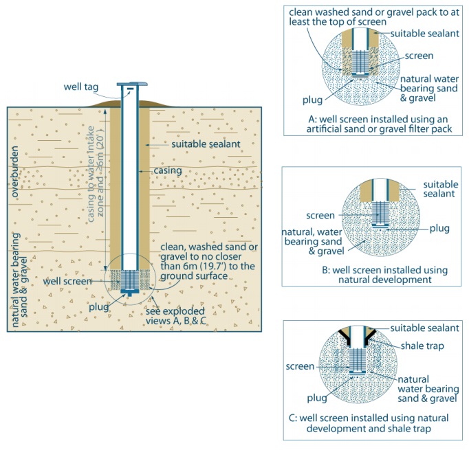
- The hole diameter must be at least 7.6 cm (3 inches) greater than the final outer casing (see A or B) for at least 6 m (19.7ft) from the ground surface or the full depth of the well (whichever is less).
- If centralizers are used with rotary equipment or a breakaway guide is used with cable tool equipment the hole diameter must be at least 5.1 cm (2 inches) greater than the final outer casing (see C) for at least 6 m (19.7ft) from the ground surface or the full depth of the well (whichever is less).
- When the only useful aquifer necessitates a shallower well, the sand or gravel must not be closer than 2.5 m to the ground surface.
- This applies to all wells other than wells constructed by the use of a driven or jetted point, dug wells and bored wells with concrete casing. This will apply to bored wells with casing other than concrete (e.g. galvanized or fiberglass).
The left side of Figure 1 shows a cross-sectional diagram example of a drilled well in overburden using a well screen.
The example shows a well completed into natural water bearing sand and gravel overburden. The bottom of the well is completed with a well screen that is located in the water bearing sand and gravel overburden. A plug is located on the bottom of the well screen. The well screen is attached to the casing. The casing extends from the top of the well screen (the water intake zone) to above the ground surface. The casing has to extend from the ground surface to at least 6 metres (about 20 feet) below the ground surface. A well cap is located at the top of the casing and a well tag is affixed to the casing above the ground surface. There is an annular space around the casing that has been filled with suitable sealant. There is an annular space around the well screen that has been filled with cleaned wash sand or gravel. The clean washed sand and gravel can be no closer than 6 metres (19.7 feet) to the ground surface. The ground surface adjacent to the casing has been mounded to prevent the ponding of water in the vicinity of the well.
There is a circle drawn around the well screen, the overburden near the well screen and the casing just above the well screen on diagram on the left side of Figure 1. There is text that states “see exploded views A, B and C” with an arrow from the text to the circle.
On the right side of Figure 1 there are the three exploded views A, B and C”.
Exploded View A is a cross-sectional diagram of a well screen installed using an artificial sand or gravel pack. The cross-sectional diagram shows the bottom of the well completed with a well screen that is located in the natural water bearing sand and gravel overburden. A plug is located on the bottom of the well screen. There is an annular space around the casing that has been filled with suitable sealant. There is an annular space around the well screen that has been filled with cleaned wash sand or gravel.
Exploded View B is a cross-sectional diagram of a well screen installed using natural development. The cross-sectional diagram shows the bottom of the well completed with a well screen that is located in the natural water bearing sand and gravel overburden. A plug is located on the bottom of the well screen. There is an annular space around the casing that has been filled with suitable sealant. The overburden has collapsed around the well screen. The overburden beside the well screen has been developed to remove nearby fine subsurface formation materials and allow groundwater from the formation to enter the well through the well screen.
Exploded View C is a cross-sectional diagram of well screen installed using natural development and a shale trap. The cross-sectional diagram shows the bottom of the well completed with a well screen that is located in the natural water bearing sand and gravel overburden. A plug is located on the bottom of the well screen. A shale trap has been placed outside the bottom of the casing in the annular space. There is an annular space around the casing above the shale trap that has been filled with suitable sealant. The overburden has collapsed around the well screen. The overburden beside the well screen has been developed to remove nearby fine subsurface formation materials and allow groundwater from the formation to enter the well through the well screen.
The diagram above is not to scale, is for illustrative purposes only and does not necessarily represent full compliance with other requirements found in the Wells Regulation (e.g. well covering).
For additional information see Chapter 5: Constructing & Casing the Well and Chapter 6: Annular Space & Sealing of the Water Supply Wells – Requirements and Best Management Practices manual.
Figure 2: Drilled Well in Overburden – Without Well Screen
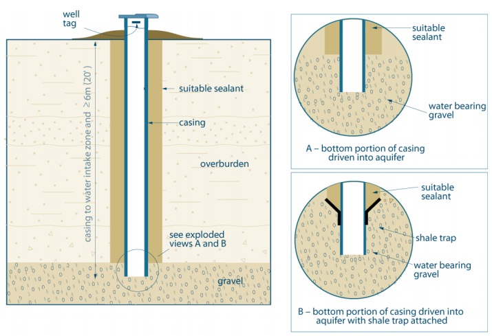
- The hole diameter must be at least 7.6 cm (3 inches) greater than the final outer casing for at least 6 m (19.7ft) from the ground surface or the full depth of the well (whichever is less).
- If centralizers are used with rotary equipment or a breakaway guide is used with cable tool equipment the hole diameter must be at least 5.1 cm (2 inches) greater than the final outer casing for at least 6 m (19.7ft) from the ground surface or the full depth of the well (whichever is less).
- This applies to all wells other than wells constructed by the use of a driven or jetted point, dug wells and bored wells with concrete casing. This will apply to bored wells with casing other than concrete (e.g. galvanized or fiberglass).
- In this example, the casing is driven down into the gravel and no annnular space is created around the bottom portion of the casing.
The left side of Figure 2 shows a cross-sectional diagram example of a drilled well in overburden without using a well screen.
The example shows a well completed into gravel overburden. The well is completed with a casing that extends through overburden into gravel overburden. The casing extends from the water intake zone to above the ground surface. The casing has to extend from the ground surface to at least 6 metres (about 20 feet) below the ground surface. A well cap is located at the top of the casing and a well tag is affixed to the casing above the ground surface. There is an annular space around the casing from the ground surface to the top of the gravel. The annular space has been filled with suitable sealant. The ground surface adjacent to the casing has been mounded to prevent the ponding of water in the vicinity of the well.
There is a circle drawn around the bottom of the casing, the overburden near the casing on diagram on the left side of Figure 2. There is text that states “see exploded views A, and B” with an arrow from the text to the circle.
On the right side of Figure 2 there are the three exploded views A, B and C”.
Exploded View A is a cross-sectional diagram of the bottom portion of the casing driven into an aquifer. The cross-sectional diagram shows the bottom of the well completed with a casing into water bearing gravel overburden. There is an annular space around the casing above the gravel that has been filled with suitable sealant.
Exploded View B is a cross-sectional diagram of the bottom portion of the casing driven into an aquifer and a shale trap attached. The cross-sectional diagram shows the bottom of the well completed with a casing into water bearing gravel overburden. A shale trap has been placed outside the casing in the annular space at the top of the gravel overburden. There is an annular space around the casing above the shale trap that has been filled with suitable sealant.
The diagram above is not to scale, is for illustrative purposes only and does not necessarily represent full compliance with other requirements found in the Wells Regulation (e.g. well covering).
For additional information see Chapter 5: Constructing and Casing the Well and Chapter 6: Annular Space & Sealing of the Water Supply Wells – Requirements and Best Management Practices manual.
Figure 3: Drilled Wells in Bedrock
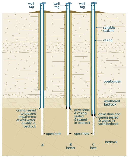
- The hole diameter must be at least 7.6 cm (3 inches) greater than the final outer casing for at least 6 m (19.7ft) from the ground surface or the full depth of the well (whichever is less).
- If centralizers are used with rotary equipment or a breakaway guide is used with cable tool equipment the hole diameter must be at least 5.1 cm (2 inches) greater than the final outer casing (see C) for at least 6 m (19.7ft) from the ground surface or the full depth of the well (whichever is less).
- In this example, the casings in A nad B are driven down into the bedrock and no annular space is created around the bottom portion of the casing.
Figure 3 shows a cross-sectional diagram example of three wells (A, B and C) drilled through overburden underlain by weathered bedrock and finally underlain by bedrock.
The well on the left of the diagram is example “A”. The well is completed with a casing that extends from above the ground surface through overburden to the top bedrock. The bottom of the casing has been sealed into the bedrock to prevent impairment of the well water quality in the bedrock. The well has been drilled into the bedrock as an open hole as the bedrock has enough strength to not collapse into the hole. A well cap is located at the top of the casing and a well tag is affixed to the casing above the ground surface. There is an annular space around the casing from the ground surface to an elevation above the top of the weathered bedrock in the overburden. The annular space has been filled with suitable sealant. The ground surface adjacent to the casing has been mounded to prevent the ponding of water in the vicinity of the well.
The well in the middle of the diagram is example “B” and is considered “better” than “A”. The well is completed with a casing that extends from above the ground surface through overburden to the top bedrock. A drive shoe (thicker piece of casing) has been attached to the bottom of the casing string. The bottom of the casing, with the drive shoe, has been sealed and seated at the top of the bedrock. The well has been drilled into the bedrock as an open hole as the bedrock has enough strength to not collapse into the hole. A well cap is located at the top of the casing and a well tag is affixed to the casing above the ground surface. There is an annular space around the casing from the ground surface to an elevation in the weathered bedrock. The annular space has been filled with suitable sealant. The ground surface adjacent to the casing has been mounded to prevent the ponding of water in the vicinity of the well.
The well on the right side of the diagram is example “C” and is considered the “best” of examples “A”, “B” and “C”. The well is completed with a casing that extends from above the ground surface through overburden to the top bedrock. A drive shoe (thicker piece of casing) has been attached to the bottom of the casing string. The bottom of the casing, with the drive shoe, has been sealed and seated below the top of the bedrock. Below the casing, the well has been drilled into the bedrock as an open hole as the bedrock has enough strength to not collapse into the hole. A well cap is located at the top of the casing and a well tag is affixed to the casing above the ground surface. There is an annular space around the casing from the ground surface to just above the bottom of the drive shoe. The annular space has been filled with suitable sealant. The ground surface adjacent to the casing has been mounded to prevent the ponding of water in the vicinity of the well.
The diagram above is not to scale, is for illustrative purposes only and does not necessarily represent full compliance with other requirements found in the Wells Regulation (e.g. well covering).
For additional information see Chapter 5: Constructing & Casing the Well and Chapter 6: Annular Space & Sealing of the Water Supply Wells – Requirements and Best Management Practices manual.
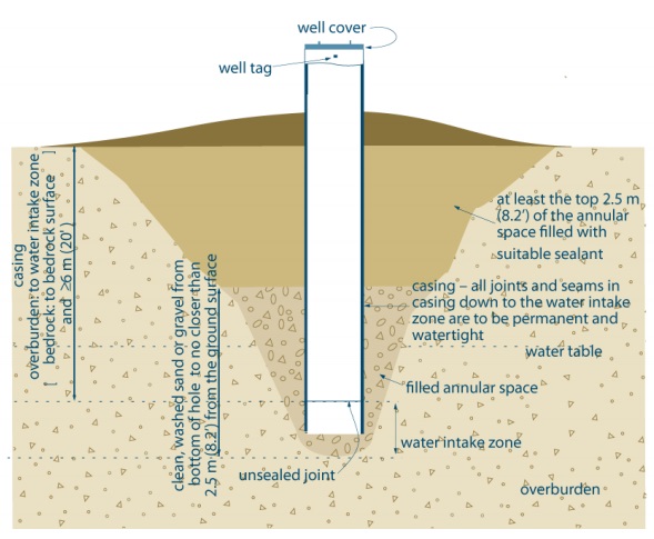
Figure 4: Bored Wells with Concrete Casing
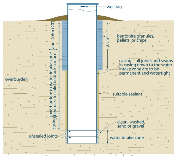
- All concrete tiles with joints that are not sealed with mastic are considered a well screen (water intake zone).
- The hole diameter must be at least 15.2 cm (6 inches) greater than the casing’s outer diameter from the land surface to a depth of 2.5 m (8.2ft).
- The hole diameter must be at least 7.6 cm (3 inches) greater than casing’s outer diameter from 2.5 m (8.2ft) to at least 6 m (20ft) below the land surface.
- Sand or gravel must be installed from at least the top of the water intake zone or screen to no closer than 6 m (20ft) below the land surface unless the only useful aquifer available necessitates a shallower well in which case clean, washed sand or gravel must be installed no closer than 2.5 m (8.2ft) from the land surface.
Figure 4 shows a cross-sectional diagram example of a bored well with concrete casing.
The example shows a bored well completed into overburden. The well consists of concrete tiles from above the ground surface into the aquifer in the overburden. The joints and seams in the concrete tiles are to be permanently watertight to the water intake zone. These concrete tiles with sealed joints are considered casing. The diagram shows two concrete tiles in the water intake zone that are unsealed. The casing has to extend from the ground surface to at least 6 metres (about 20 feet) below the ground surface. If the well extends into the bedrock, the casing has to extend to the competent bedrock surface. A well cover is located at the top of the casing and a well tag is affixed to the casing above the ground surface. There is an annular space around the concrete tiles. In the water intake zone, the annular space is filled with cleaned, washed, sand or gravel. From the water intake zone to 2.5 metres (8.2 feet) below the ground surface, the annular space has been filled with suitable sealant. From the ground surface to 2.5 metres (8.2 metres) below the ground surface, the annular space has been filled with bentonite granules, pellets or chips. There is an annular space around the well screen that has been filled with cleaned wash sand or gravel. The clean washed sand and gravel can be no closer than 6 metres (19.7 feet) to the ground surface. The ground surface adjacent to the casing has been mounded to prevent the ponding of water in the vicinity of the well.
The diagram above is not to scale, is for illustrative purposes only and does not necessarily represent full compliance with other requirements found in the Wells Regulation (e.g. well covering).
For additional information see Chapter 5: Constructing & Casing the Well and Chapter 6: Annular Space & Sealing of the Water Supply Wells – Requirements and Best Management Practices manual.
Figure 5: Dug Well
- All concrete tiles with joints that are not sealed with mastic are considered a well screen (water intake zone).
- Sand or gravel can be replaced with native material (soil) that was excavated from the hole, if the well is not constructed in a contaminated area and the horizons of soil are excavated separately, stored separately, kept free from contamination and backfilled in the same relative positions that they originally occupied.
- Suitable sealant that is used to fill annular space must provide appropriate structural strength to support the weight of persons and vehicles that may move over the well area after it is filled.
Figure 5 shows a cross-sectional diagram example of dug well.
The example shows a dug well completed into overburden. The well consists of casing that extends from above the ground surface to below the water table in the overburden. The joints and seams in the casing are to be permanently watertight to the water intake zone. The diagram shows an unsealed joint between two pieces of casing in the water intake zone. The casing has to extend from the ground surface to at least 6 metres (about 20 feet) below the ground surface. If the well extends into the bedrock, the casing has to extend to the competent bedrock surface. A well cover is located at the top of the casing and a well tag is affixed to the casing above the ground surface. An area below the casing has been filled with clean, washed sand or gravel. There is an annular space around the casing. The annular space from the bottom of the casing to 2.5 metres (8.2 feet) below the ground surface has been filled with clean, washed sand or gravel. From the ground surface to 2.5 metres (8.2 feet) below the ground surface, the annular space has been filled with suitable sealant. The ground surface adjacent to the casing has been mounded to prevent the ponding of water in the vicinity of the well.
The diagram above is not to scale, is for illustrative purposes only and does not necessarily represent full compliance with other requirements found in the Wells Regulation (e.g. well covering).
For additional information see Chapter 5: Constructing & Casing the Well and Chapter 6: Annular Space & Sealing of the Water Supply Wells – Requirements and Best Management Practices manual.
Figure 6: Driven Point Well
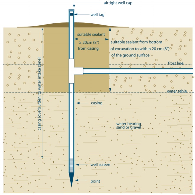
- The excavation has been created as a result of installing pumping equipment. To see how this is filled see Chapter 9: Equipment Installation, for further instructions.
- If any annular space is created during the driving of the casing, the annular space must be completely filled using materials and a method approved in writing by the director.
Figure 6 shows a cross-sectional diagram example of driven-point well.
The example shows a driven-point well completed into the subsurface. The well consists of casing that extends from above the ground surface to below the water table in a water bearing sand and gravel overburden. The casing extends to the water intake zone. A well screen is attached to the bottom of the casing. A drive-point is attached to the bottom of the well screen. An airtight well cap is located at the top of the casing and a well tag is affixed to the casing above the ground surface. Below the frost line in the subsurface a horizontal water line connects to the casing. The excavation that was created to connect the horizontal waterline to the casing has been filled with suitable sealant from the casing to at least 20 centimetres (8 inches) from the casing and from the bottom of the excavation to at least 20 centimetres (8 inches) from the ground surface. The ground surface adjacent to the casing has been mounded to prevent the ponding of water in the vicinity of the well.
The diagram above is not to scale, is for illustrative purposes only and does not necessarily represent full compliance with other requirements found in the Wells Regulation.
“Chapter 9” in the first bullet under the figure refers to Chapter 9: Equipment Installation of the Water Supply Wells – Requirements and Best Management Practices manual.
Figure 7: Jetted Point Well
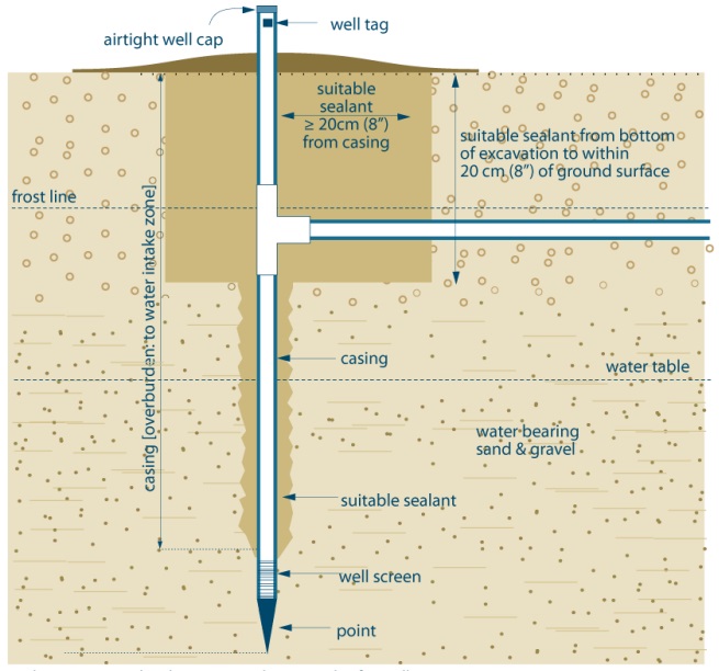
- The excavation has been created as a result of installing pumping equipment. To see how this is filled see Chapter 9: Equipment Installation, for further instructions.
- A person constructing a well by jetting typically creates an annular space around the well casing. The person constructing the well by jetting must ensure that any annular space around a well casing is sealed to prevent any movement of water, natural gas, contaminants, or other material between subsurface formations (aquifers) or between a subsurface formation and the ground surface.
Figure 7 shows a cross-sectional diagram example of a jetted point well.
The example shows a jetted point well completed into the subsurface. The well consists of casing that extends from above the ground surface to below the water table in a water bearing sand and gravel overburden. The casing extends to the water intake zone. A well screen is attached to the bottom of the casing. A drive-point is attached to the bottom of the well screen. An airtight well cap is located at the top of the casing and a well tag is affixed to the casing above the ground surface. Below the frost line in the subsurface a horizontal water line connects to the casing. The excavation that was created to connect the horizontal waterline to the casing has been filled with suitable sealant from the casing to at least 20 centimetres (8 inches) from the casing and from the bottom of the excavation to at least 20 centimetres (8 inches) from the ground surface. An irregular annular space is located adjacent to the outside of the casing from below the filled excavation to the top of the well screen. The annular space has been filled with suitable sealant. The ground surface adjacent to the casing has been mounded to prevent the ponding of water in the vicinity of the well.
The diagram above is not to scale, is for illustrative purposes only and does not necessarily represent full compliance with other requirements found in the Wells Regulation.
“Chapter 9” in the first bullet under the figure refers to Chapter 9: Equipment Installation of the Water Supply Wells – Requirements and Best Management Practices manual.
Footnotes
- footnote[1] Back to paragraph The structural stage is complete on the day on which the well is capable of being used for the purpose for which it was constructed except for pump installation and disinfection of the water in the well in accordance with the Wells Regulation.