Environmental guidelines for access roads and water crossings
Direction on the construction and maintenance of access roads and water crossings in a forest environment.
©1990, Queen’s Printer for Ontario
Printed in Ontario, Canada
Single copies of this publication are available for $5.25 from the address noted below.
Current publications of the Ontario Ministry of Natural Resources, and price lists, are obtainable through the Ministry of Natural Resources Public Information Centre, Room 1640, Whitney Block, 99 Wellesley St. West, Toronto, Ontario M7A 1W3 (personal shopping and mail orders).
Telephone inquiries about ministry programs and services should be directed to the Public Information Centres:
Fisheries/Fishing Licence Sales –
Wildlife/Hunting Licence Sales –
Provincial Parks –
Forestry/Lands –
Aerial Photographs –
Maps –
Minerals –
Cheques or money orders should be made payable to the Treasurer of Ontario, and payment must accompany order.
Other government publications are available from Publications Ontario, Main Floor,
880 Bay St., Toronto. For mail orders write MGS Publications Services Section, 5th Floor, 880 Bay St., Toronto, Ontario M7A 1N8.
1.0 Preface
This manual provides a collection of guidelines for those involved with access roads on Crown land in Ontario. It will assist them in carrying out their projects with a minimum of disturbance to the natural environment.
These guidelines were prepared following an extensive review of guidelines used for similar purposes in other jurisdictions. Section 9 contains a partial list of these other publications.
A technical advisory group assisted in developing the manual’s final text.
Organizations represented within the advisory group included various disciplines within the Ministry, the Ontario Forest Industries Association, the Ontario Lumber Manufacturers Association and the Ontario Ministry of the Environment.
The group’s participation ensured the publication reflects the knowledge and field observations of experienced people from a cross-section of public and private sector organizations that have an interest in access roads and water crossings in Ontario.
The Ministry of Natural Resources gratefully acknowledges the following people for their participation within the technical advisory group.
Ministry of Natural Resources:
Bruce Adamson, Chairman
Regional Engineer
North Central Region
Thunder Bay
Cam Clark
Policy Officer
Assistant Deputy Minister’s Office
Thunder Bay
Linda Jackson
Policy Officer
Land Management Branch
Toronto
Brian Martyniuk
Engineering Services Technician
Thunder Bay District
Thunder Bay
Alan Parkinson
Environmental Planner
Planning and Environmental Assessment Branch
Toronto
Don Stillar
Timber Management Supervisor
Cochrane District
Greg Vaughan
Senior Lands Technician
Bracebridge District
Neville Ward
Regional Fisheries Biologist
Northwestern Region Kenora
Outside Participants:
Paul Abbott
Communications Consultant
The Abbott Jenkins Design Group
Toronto
George Blight
Consultant to Forest Industry
Amisk Forest Services Limited Hearst
Bill Creighton
Manager, Technical Support
Ministry of the Environment
Thunder Bay
Larry Hicock
Principal Writer
The Abbott Jenkins Design Group
Toronto
Ray Townsend
Operations Superintendent
The Algonquin Forestry Authority
Huntsville
Rudy Zorn
Construction Superintendent
Canadian Pacific Forest Products Limited
Thunder Bay
2.0 Introduction
2.1 Why guidelines?
It is expected that most planners, developers, operators and others involved in road development projects share a concern for the well-being of the natural environment. The potentially harmful effects of access road activities can be eliminated or minimized by decision makers who have an understanding of good environmental practices and use that knowledge effectively.
Various environmental values should be considered during the planning, construction, maintenance and abandonment of access roads and water crossings. These include:
- aquatic (water quality and fisheries)
- terrestrial (plants and animals)
- recreation, cottaging and tourism
- historical and archaeological
- aesthetics (at some locations)
- air quality (dust abatement, pollution control)
- noise levels
- worker and public safety
- economic considerations
The purpose of this manual is to establish standards and provide practical advice for ensuring minimum disturbance to the natural environment (aquatic, terrestrial). Other values outside the scope of these guidelines, for example tourism or archaeological, may require the implementation of specific mitigation techniques to minimize the effects of access roads on that value. These would normally be identified and prescriptions developed at the planning stage of the project, possibly referring to other guideline documents that are available.
The specific objectives of this manual are:
- To provide up to date environmental guidelines appropriate for the construction, maintenance and abandonment of access roads and water crossings.
- To establish mandatory standards to be followed when constructing, maintaining and abandoning access roads and water crossings on Crown land to ensure a minimum level of environmental protection.
- To record and disseminate information about good practices being used in Ontario which have proven effective in minimizing the impact on the environment.
- To provide design information about special mitigation techniques that may be used to eliminate or reduce potential negative environmental impacts.
The decisions and actions of those involved in planning, constructing and maintaining access roads and water crossings have a significant influence on how much impact those activities have on the natural environment. By using this publication access objectives can be met while the extent and duration of environmental impacts are minimized.
In many cases implementation of the recommendations does not require any additional expenditure of money. In fact, doing it right the first time is often more economical in the long run because it avoids costly mistakes that may have to be rectified. Good practices lead to efficient, cost-effective construction projects. They will ensure that access roads and water crossings will continue to function with a minimum of maintenance problems and a minimum of adverse environmental impacts.
Adherence to the manual’s guidelines will help to assure compliance with relevant legislation. As a result, technical or legal irregularities can be avoided before they arise.
2.2 Application of this manual
This manual applies to the planning, construction, maintenance and abandonment of access roads on Crown land in Ontario. These activities are subject to the Environmental Assessment Act and to the Lakes and Rivers Improvement Act. The guidelines complement other pertinent guidelines and procedures such as the Guidelines and Criteria for Approval Under the Lakes and Rivers Improvement Act, Access Road Strategies and Guidelines, Fish Habitat Guidelines, Moose Habitat Guidelines, and Tourism Guidelines.
It is a requirement of the Class Environment Assessment for Timber Management in Ontario that this manual be followed for road access activities undertaken as part of timber management. The Ministry of Natural Resources will be responsible for monitoring compliance of the private sector, as well as its own staff, with these guidelines. Where necessary, the Ministry of Natural Resources or the Ministry of the Environment will undertake enforcement related to the statutes under their administration.
Although developed for use as support to the Class EA for Timber Management, the good environmental principles and guidelines set out in the manual have application to all access roads, regardless of their purpose. This publication supercedes portions of the Construction and Mitigation Handbook dealing with access roads.
There are a wide variety of access road types and standards constructed in Ontario. The potential harmful effects on the natural environment are influenced by the physical site conditions, the activity being undertaken, the road standard, the life of the road and abandonment procedures. The potentially negative effect of a poorly installed water crossing on an important spawning bed is not lessened because it is located on a tertiary road and not a primary road. For this reason it is intended the manual will apply to all access roads on Crown land regardless of type, standard or duration of use. It is not intended to apply to roads on dedicated rights-of-way such as those under the jurisdiction of the Ministry of Transportation, Municipalities or Ontario Hydro.
2.3 Using this manual
The manual is a comprehensive collection of mandatory standards, good practice guidelines and mitigation techniques. There will be variation in practice from area to area and some of the operations described may not apply to some roads. The guideline should be applied where necessary and appropriate to prevent or minimize a potentially harmful effect on the environment. The manual is a source of information for decision-makers to draw upon to accomplish this objective.
This manual is divided into several sections. It is important to understand the manner in which these relate to each other.
Legislation and mandatory standards set out the minimum criteria that must be followed to prevent unnecessary or unacceptable environmental changes. It is expected they will be followed in all circumstances.
Adherence to the mandatory standards does not guarantee automatic compliance with applicable legislation. In situations where mandatory standards are inadequate to protect fisheries habitat, water quality or other values, appropriate good practice and mitigation techniques must be selected and used to ensure legislative standards and requirements are met. For example, if a specific objective such as protection of a fish spawning bed, is not met by following the mandatory standards then additional site specific measures may become necessary to ensure compliance with the Fisheries Act.
Good practice guidelines are provided for each component of planning, constructing, maintaining and abandoning access roads and water crossings. Most are based on simple common sense principles. Adherence to them will minimize potential harmful effects on the natural environment. As with all guidelines, flexibility is expected in their application, however they should be followed to the extent reasonably possible throughout the entire road length.
Mitigation techniques are the means by which construction activities can be modified to minimize or eliminate potential negative impacts at specific locations where important values must be protected. The techniques described in the manual are primarily focussed on erosion and sediment control at water crossings.
In areas of unique or special values, identified prior to or during construction, it may be appropriate to specify some of the good practice guidelines or mitigation techniques as mandatory requirements to mitigate possible negative impacts. In this way managers involved in road construction can draw on the information contained in the guidelines to utilize appropriate construction techniques in the protection of identified values along the route of the road.
A section containing a glossary of terms is provided to define technical and construction terminology as it is used in the manual. A list of publications used as a source of information during development of the manual is provided.
It may be useful to readers who wish further details on specific areas of interest.
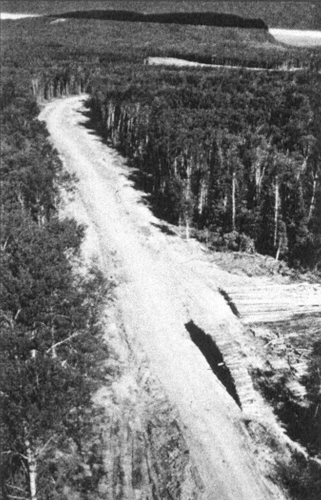
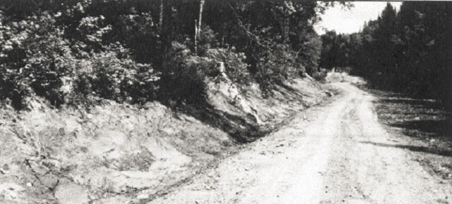
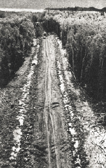
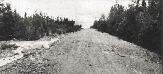
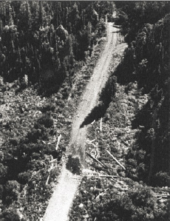
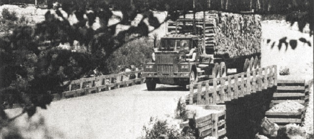
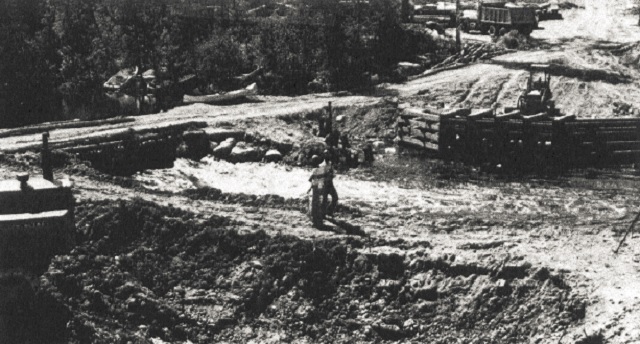
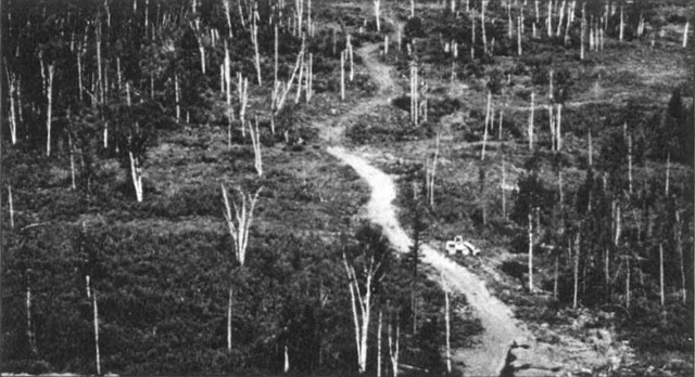 The guidelines contained in this manual apply to all types of access roads, including this tertiary road.
3.0 Applicable legislation
3.1 Introduction
This section summarizes most of the special Federal and Provincial legislation applicable to the construction of access roads and water crossings on Crown land.
Included is a brief description of each of the Acts which require a permit or application for approval. Activities associated with access road and water crossing construction on Crown land that require such approvals and/or permits include the following:
- Cutting of timber on Crown land.
- Construction of a water crossing
- Any activity on Crown land during the forest fire season.
- Construction near a water body that could have a detrimental effect on fish habitat or water quality.
- Development and operation of a borrow pit or gravel pit.
- Any activity associated with timber management on Crown land.
3.2 Federal legislation
The Fisheries Act - This Act requires the protection of fish habitat; administered in Ontario by the Ministry of Natural Resources.
Navigable Water Protection Act - Under this Act, any construction in or over a navigable water body requires an application and approval; administered by the Ministry of Transport, Canadian Coast Guard.
The Railway Act - Construction and regulation of matters related to railways come under this legislation, including railway crossings; administered by the National Transportation Agency of Canada.
3.3 Provincial legislation
Crown Timber Act - Authority to cut wood on Crown land, including right-of-way clearing. It has penalties to deal with wasteful practices and the destruction of timber; administered by the Ministry of Natural Resources.
Environmental Assessment Act - Activities of the Government of Ontario, including the construction of roads, fall under this legislation. Timber management in Ontario, including the construction of roads by the forest industry, is subject to the provisions of this legislation; administered by the Ministry of the Environment.
Environmental Protection Act - Contains regulatory requirements pertaining to air, water, land and noise pollution; covers the required approval of sewage and solid waste disposal sites; administered by the Ministry of the Environment.
Forest Fire Prevention Act - A Work Permit, to authorize any work on Crown land and to ensure that adequate forest fire precautions and equipment are in place, is required; administered by the Ministry of Natural Resources.
The Lakes and Rivers Improvement Act - Approval is required for the construction of a dam
across a watercourse. A bridge or culvert may act as a dam in certain circumstances. A technical review is necessary to determine if an application is required; administered by the Ministry of Natural Resources.
The Mining Act - a Quarry Permit is required to develop and operate a borrow or gravel pit in areas of the Province excluded from the Pits and Quarries Control Act; administered by the Ministry of Natural Resources.
Occupational Health and Safety Act - Regulation 692 contains provisions applying to timber haul roads, such as road signs and the structural capacity of bridges. The Act also covers safety on construction sites; administered by the Ministry of Labour.
Ontario Heritage Act - Permits are required for excavation or alteration of archeological and historical sites; administered by the Ministry of Culture and Communications.
Ontario Water Resources Act - The Act prohibits the discharge or deposit of any material into any waterbody which may impair the water quality or may cause injuries to any person or living thing; administered by the Ministry of the Environment.
Pesticides Act - Regulates the availability, sale, use, transportation, storage and display of all pesticides. The use of herbicides on access roads requires that the pesticide be federally registered, provincially classified and applied by a licensed applicator. The use of certain pesticides requires a special use permit; administered by the Ministry of the Environment.
The Pits and Quarries Control Act - a Quarry Permit is required to develop and operate a borrow or gravel pit in areas of the Province where this Act applies; administered by the Ministry of Natural Resources. New legislation is proposed to replace this Act with the Aggregates Act which will apply to the whole Province.
Public Lands Act - Authority to construct roads on Crown land; authority for Crown cost-sharing of company roads; sets out limitations on liability, tenure for private forest roads, camp areas, defines applicability of the Highway Traffic Act on access roads; authority for use restrictions; administered by the Ministry of Natural Resources.
The Public Transportation and Highway Improvement Act, and associated Cabinet Approved Policy Statements - These address Provincial Highways, District, County and Municipal roads. Since some roads fall under the Controlled Access Criteria
, entrance permits will be necessary and applications must be made to the appropriate government agency controlling such roadways; administered by the Ministry of Transportation.
4.0 Mandatory standards
The following list sets out standards that are considered mandatory to protect the natural environment within which access roads and water crossings are built. These standards must be adhered to by anyone planning, constructing, maintaining and abandoning access roads or water crossings as part of timber management on Crown land in Ontario. Their use is encouraged on access roads for purposes other than timber management.
- All applicable legislation, as identified in Section 3, must be complied with. Those persons responsible for construction must ensure the necessary approvals and permits are in place before physical site work begins. Conditions of those approvals and permits must be met.
- A use management strategy for each primary and secondary road or for each timber management unit must be developed; this is to include consideration of other uses and abandonment when the road is no longer needed for its original purpose.
- Areas of concern identified during the planning process must be adequately addressed. Areas of concern include locations where particular values are to be protected and environmentally sensitive areas which require special attention. Appropriate mitigation techniques must be followed throughout the planning, design, construction, maintenance and abandonment of the road.
- Other uses of Crown land identified in advance (e.g. staked corner posts for mining, trenches, grid markers, trapper’s cabins, boat caches) must not be disturbed unless approval to do so has been given by the lessor and by the Ministry of Natural Resources.
- Water crossing proposals must be reviewed by the Ministry following the Guidelines and Procedures for Approval Under the Lakes and Rivers Improvement Act. This review may lead to a determination of: construction time restrictions; a minimum waterway opening size; special mitigation requirements for preventing flooding and/or minimizing detrimental impacts on fish habitat and water quality. To avoid delays, this review should occur well ahead of the proposed road construction.
- During the construction and maintenance of access roads and water crossings, appropriate measures must be taken to prevent contamination of water bodies by foreign materials such as lumber, nails, logs, brush, fuel, oil, lime, cement, asphalt, calcium chloride, sodium chloride, oil base wood preservatives and herbicides. No herbicides are to be sprayed within 10 metres of a water crossing.
- Clearing operations in rights-of-way must conform with the requirements of the Crown Timber Act, including the harvesting and utilization of salvageable wood.
- Materials moved during construction, such as grubbing, earth fills and earth cut materials must not be piled where they block drainage courses.
- The use of heavy construction machinery on streambeds is not permitted during spawning and incubation periods and must be kept to an absolute minimum at other times.
- Waterways must not be blocked so as to impede the free movement of water and fish.
- Clearing and grubbing of low vegetative cover within 100 m (350 feet) of a water crossing, or other water body identified as being sensitive by the Ministry, must be kept to the absolute minimum necessary for constructing the project.
- Exposed mineral soil within 100 metres (350 feet) of a water body must be graded to a stable angle of repose to prevent erosion.
- Appropriate erosion control and/or sedimentation control measures are to be undertaken to protect water quality.
- Access routes to lakes and streams outside the road right-of-way limits must not be constructed without the approval of the Ministry.
- Permanent diversion or channelization of an existing water course is generally inadvisable and, if undertaken, must not create any more disturbance of the natural environment than absolutely necessary. Waterway size and erosion resistance of the new channel must be comparable to those of the natural channel unless a special engineering analysis and design justifies an alternative approach. The new channel must be constructed in the dry to the maximum extent possible.
- Fill material placed below high water level within the floodplain of water bodies must be erosion resistant.
- Construction techniques used at water crossings must be selected to protect water quality. This may require the selection and use of special mitigation techniques.
- Fill slopes and waterway banks disturbed during construction must be trimmed to a stable angle of repose. Upon completion of a water crossing, any temporary fill, culverts, refuse, etc. must be removed from the construction area and disposed of in a satisfactory manner.
- Staff, as part of their normal field duties are expected to observe, on an annual basis, the condition of water crossings on maintained roads, particularly with respect to the potential for washouts or blockages of culverts. Problems are to be reported to the appropriate road authority.
Naturally abandoned roads
will be inspected at least once every three years and more frequently where circumstances, such as abnormal rainfall, warrant.- When a road is
physically abandoned
footnote 1 appropriate measures are to be taken to prevent significant erosion and sedimentation of water bodies. These measures may include the removal of culverts and bridges and grading of slopes to stable angles of repose.
5.0 Access roads – good practices
5.1 Introduction
The construction of access roads can cause significant disturbance to the natural environment. The seriousness of the impact depends on many factors, including:
- type of natural environment
- terrain difficulty
- soil types along the route
- construction materials used
- geometric road standard
- construction and maintenance practices
- a mitigation techniques implemented
- road abandonment practices
The good practices described in this section apply to all types of roads. It is recognized that not all guidelines may be relevant to all roads, however even low standard tertiary roads have the potential for causing significant harmful effects. The practices described should be consulted as a matter of course prior to and during the management of access road projects.
Access road activities can be subdivided into a series of operations that take place in a chronological sequence. Using this sequence, the good practices have been grouped into the following components:
- road planning and location
- a clearing
- grubbing
- earth grading
- a rock grading
- drainage ditches and culverts
- swamp treatments
- graveling
- road maintenance
- road abandonment
5.2 Road planning and location
This phase comprises the preconstruction components of the corridor study, road location and road design.
The level of technical evaluation, layout and design required on a particular road depends on the geometric standard, the terrain through which the road will be built and the method of construction. At this stage, the final alignment of the road is selected. Decisions about the location of a particular road have an important influence on the impact the road will have on the natural environment.
Good practices - location:
- Ensure areas of concern in the planning stage have been identified and dealt with. This may require special mitigation techniques such as protection of canoe routes, erosion control at water crossings, building neat push-outs for aesthetics, avoidance of osprey nests.
- Select the location of water crossings well in advance of construction, particularly those identified in Timber Management Plans.
- Avoid unfavourable construction areas as much as possible. These include hilly terrain with steep grades (10% or more); areas with insufficient gravel; deep swamps; bedrock; erodible soils; and shallow soils areas.
- For environmental as well as practical considerations, road alignments should follow the contours of the land.
- Gentle grades (1-4%) are desirable for proper drainage and economical construction.
- Long, sustained grades should be avoided since they allow excessive runoff buildup in ditches and can lead to erosion.
- Keep roads away from recreational areas, water bodies and wetlands, except where water access or aesthetic viewing is an objective of the road.
- Buffer zones of undisturbed vegetation between access roads and water bodies should be maintained and should increase in width proportionally to the increase in slope of land entering the waterway.
- Minimize the number of water crossings.
- Geometric road standard should be appropriate for the intended use and for the duration of use of the road. Construction to a higher standard than necessary increases costs and has the potential for more environmental damage.
- Identify sources of material for road construction, and consider locating the road near these sources, in order to minimize haul distances and provide better materials to work with.
- Landings, loading areas and turnarounds should be located when the road is being laid out. Landings should be on high ground to avoid rutting and blocking of drainage paths.
5.3 Clearing
Clearing consists of cutting and removing standing trees to make room for construction of the road. It is normal practice to specify a minimum width of clearing. This is done for several reasons: to allow space for construction equipment to operate without knocking down standing trees; to provide safe sight lines around curves; and, to allow drying of the roadway in wet weather and spring break-up. Maximum widths should also be specified to minimize the areal extent of disturbance caused by road construction.
The equipment normally used for clearing includes chainsaws, bulldozers, wheeled skidders and other loading, slashing and haulage equipment for wood handling.
Good practices - clearing
- Do not clear an area larger than necessary to meet the geometric standard for the road; control clearing width using marked sidelines.
- Reduce clearing width to the minimum needed for construction within 100 metres (350 feet) of a water crossing, or a water body identified by the Ministry as being sensitive.
- Away from water crossings, a minimum width of 20 metres (66 feet) should be cleared to ensure the road will dry out, and to provide sight lines for safety.
- Trees should be felled away from standing bush and water bodies.
- Push-outs should be pre-cut. Locate them on the low side of the road, but without blocking drainage.
- Landings should be pre-cut, on high ground, off the right-of-way, and in scrub brush areas if possible.
- Salvage merchantable timber from right-of-way clearing.
- Clear in winter months to reduce rutting.
- Slash debris should be disposed of as part of the grubbing operation.
5.4 Grubbing
Grubbing, or stripping, consists of the removal and disposal of stumps, roots, brush, small trees, embedded logs and organic material overlying the mineral soil.
Grubbing is done to expose the mineral soil for three reasons:
- To prepare for earth grading operations.
- To improve roadway performance by eliminating weak organic material in the zone carrying wheel loads; and
- To minimize future sight distance problems that roadside vegetation could cause.
Full width grubbing is done where road-building materials are expected to come from the right-of-way area. Occasionally, in certain soil conditions and on low standard roads, the grubbing material is pulled to the centre and trampled down to form part of the roadbed. On some roads, especially in deep fill areas, it is acceptable to not grub; this will minimize impact on natural environment. It should be kept in mind that it is the grubbing operation which exposes mineral soil to erosion and compaction.
The equipment usually used in the grubbing operation are bulldozers and backhoes. Special blades have been developed for bulldozers, featuring rake-like teeth or small shoes that elevate the blade to allow collection of the brush and stumps while leaving the organic topsoil on the right-of-way. It is useful to use this equipment to retain low vegetation and to minimize erosion problems.
Good practices - grubbing:
- To ensure that trees on the bush line are not under-cut, a cleared but not grubbed buffer should be left along the edge of the right-of-way.
- Grubbing should not proceed too far ahead of construction. This will limit the time that the mineral soil is exposed to erosion.
- Grubbing material should not be piled where it will block drainage courses.
- If windrows are used, they should be kept behind roadside ditches and breaks should be provided so animals can move across the right-of-way, say 5 metres every 65 metres (16 feet every 200 feet).
- If push-outs are used, they should be pre-cut to a large enough size to avoid knockdown of standing trees.
- Swamps should not be grubbed.
- The stumps in swamp areas should be shear bladed in winter if possible.
- If some organic material is left in place, it will make nutrients available to ensure rapid re-vegetation of the right-of-way. This can be done by using special blades or attachments on a bulldozer and by grubbing in winter when the blade can ride on the frost.
- In areas of fine grained soils (clays, silts and fine sands) which are subject to erosion, the area to be grubbed should be minimized.
- Grubbing in fine grained soil should be avoided during wet weather. This will prevent severe rutting and unnecessary disturbance of the clay or silt soil. Postpone the grubbing operation until drier conditions prevail, or close-cut the trees and do not grub.
5.5 Earth grading
Earth grading reshapes the original ground contours to the shape of the road, in profile and cross-section.
The operation includes the excavation of earth cuts and the construction of earth fills. Lower standard roads tend to follow the original ground contours more closely, because their geometric requirements are less critical; this means that cut and fill depths will be less than those for a higher-standard road constructed along the same route.
The equipment normally used includes bulldozers, front-end loaders, backhoes, dump trucks and scrapers. In poor soil areas, the use of backhoes for building fills - by pulling in material from within the right-of-way - is a preferred method. It allows for better material selection and creates less disturbance. Rather than having the material pushed into position, a backhoe picks the material up, moves it, then places it where needed; this gives the fill a chance to dry out and consolidate before it has to carry heavy traffic.
The use of well-drained, granular soils produces strong roadbeds that are easier to construct, and that will be erosion resistant. By paying close attention to the shaping of the earth cross-section and the selection of materials, and by providing for good drainage, initial costs will be minimized, maintenance costs will be reduced and potential detrimental impacts on the environment will be prevented.
Good practices - earth grading:
- Soil instability due to soft clay, springs or erosion can result in road failure. Treat soil instability by reducing the loading (fill height) or with counterbalancing side berms. Treat persistent springs with sub-surface drainage.
- Where there are potential serious consequences of soil instability or erosion, erosion control techniques should be used promptly.
- Retain natural vegetation near water crossings as long as possible, to reduce the time that the soil is exposed; i.e., delay cut excavations under the road-bed until the last moment.
- Do not dump waste material in areas that may block the flow of water.
- Fill in or around water bodies should be constructed with earth-free rock or clean, well-graded, granular material; this will help reduce the impact on fish habitat and water quality.
- Install drainage culverts as part of the earth grading operation.
- Excavate cuts uphill to improve drainage and make material more workable. Complete ditches as cuts are being excavated.
- Keep earth fills and earth cuts as shallow as possible, consistent with the geometric standard being constructed. A road surface about one metre (three feet) above the original ground should be satisfactory for most roads, if the terrain is favourable.
- Grade and crown the earth grade as it is being constructed, to shed water and minimize ponding in ruts.
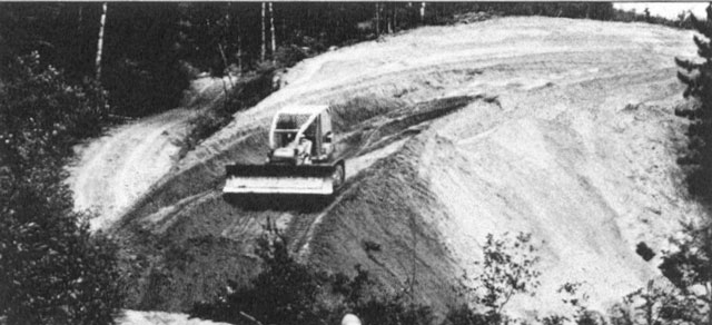
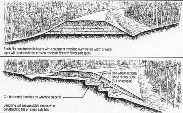
- Fills should be constructed in shallow, full width layers with stable side slopes (1-5 to 2.0:1). Equipment should be made to travel the full width of each layer to compact it and make the fill more dense. This will minimize slope erosion and soft shoulders.
- When building fills on side slopes, benching into the original ground will prevent slippage along the interface.
- When borrow from outside the right-of-way must be trucked in, try to obtain granular material. It makes a strong roadbed, drains well, is easy to compact, and is erosion-resistant.
- Limit the number of pits to minimize the area of disturbance.
- When obtaining material by excavation within or adjacent to the right-of-way, try to drain low pockets. This may not be necessary when standing water does not create any problems, e.g., in deep fill areas.
- Maintain adequate control over grading operations to ensure the road is not over-built or under-built. This usually requires some survey layout, staking limits of cuts and fills, and supervision by a grading foreman.
- When working with wet, fine-grained soils (clays, silts), it may be necessary to push the material up and leave it to dry for some time. When dry, such otherwise unsuitable materials can make an acceptable roadbed. Use of the backhoe for this operation may speed the drying time and reduce damage to the original ground.
5.6 Rock grading
Rock grading is the removal and movement of solid rock or large boulders to the desired gradeline. The operation involves stripping the overburden, drilling, blasting, excavating, transporting and placing of the material into rock fills.
As with earth grading, the desired road profile determines cut and fill requirements. For economic reasons, rock cut areas are avoided if at all possible during location of the road. In the construction of access roads, it is accepted practice to make a road more winding, or to steepen road grades to avoid rock excavation.
Rock grading equipment normally includes compressors, air track rock drills, backhoes, front-end loaders, bulldozers with ripper attachments, rock trucks and dump trucks.
Good practices - rock grading:
- Plan rock fracture to produce usable size particles for rip rap and other needs on the construction project.
- Plan drilling patterns and limit explosive loadings to an appropriate level that will shatter the rock and heap it up vertically, but will not throw the material into the bush. This will limit damage outside the right-of-way and make the material available for fill or other uses.
- Where ditches leading downhill from rock cuts pass over earth material, rip rap should be provided to protect the earth/rock interface from erosion.
- Where bedrock projects into the ditch line of a roadside ditch, construct an off take ditch into the bush, install a cross culvert, or excavate through the rock knob.
5.7 Drainage ditches and culverts
Drainage consists of the excavation of roadside ditches, the installation of cross culverts and the provision of off-take ditches. It is important to differentiate between drainage culverts and water crossings. The drainage culverts discussed in this section are those required to pass local surface flows channelized by the road construction. There is no defined channel prior to construction and there are no fish in these channels. Water crossings occur where the road crosses a natural water course that has a defined channel, they are dealt with in Section 6. All culverts should be installed in a manner which minimizes sedimentation as the downstream receiving water will eventually be fish bearing.
With proper drainage and protection from standing water, most soil types can be used to make economical access roads. A well-drained roadbed can support heavier loads, and will be usable for more of the year, than an improperly drained road. Furthermore, it can usually be constructed with less material than would be needed if good drainage was not provided. Proper roadside drainage reduces erosion and damage to inundated trees and vegetation.
The usual equipment for this operation includes bulldozers, backhoes, front-end loaders, graders and dump trucks.
Good engineering practice is usually good environmental practice. Soft roadbeds, washouts and sedimentation are generally the consequences of improper culvert installations or lack of ditching.
Good practices - culverts:
- Use permanent materials on permanent roads (e.g., csp culvert). If the road is temporary, culverts and fill deposited in the floodplain should be removed when no longer required.
- Installation should be done in driest possible time of the year.
- Installation should be carried out ahead of fill construction or as part of it.
- Culverts should be placed so that 10% of their diameter is below the original ground elevation. A high culvert will cause ponding upstream and outlet erosion downstream. Too low a culvert will fill with sediment and may freeze over in the winter. A single larger pipe may be preferable to several smaller ones, because it should be less susceptible to blockage or icing.
- In swamps, culverts should be placed where the organic depth is least to minimize settlement.
- Where cross-culverts are used on down grades to divert flow and minimize ditch erosion, they should be angled across the road so water will flow easily.
- When foundation conditions are such that a sagging of the central portion of the culvert is anticipated, the central portion should be installed with an upward camber. Anticipated sag will then tend to restore the culvert to a constant gradient.
- Culvert length should be selected to ensure ends will not be blocked by fill slopes.
- The minimum culvert size used on roads needed for more than ten years should be 500 millimetres (18 inches) in diameter.
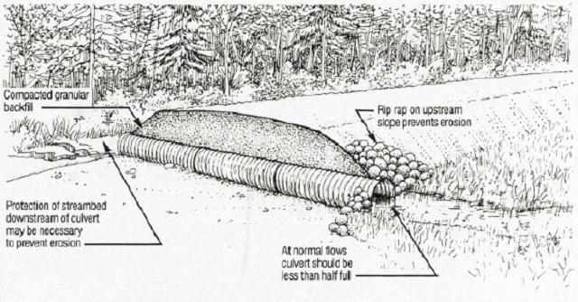
- Rip rap should be placed on the upstream fill slope around the culvert inlet, to the top of the pipe, to prevent fill washout during high flow periods.
- If scour of the streambed downstream of the culvert is expected due to the high flow velocities, an erosion resistant apron or energy dissipater should be provided.
Good practices - ditches:
- Ditching should be carried out as part of earth grading, to encourage good drainage early and to minimize soil disturbance.
- Ditches should be constructed uphill, to avoid trapping rainwater.
- All roadside ditches should flow to an outlet downstream of the road right-of-way.
- Ditches should be sized to handle the expected runoff from the area draining onto them. Large drainage areas may require deeper or wider ditches than are normally provided.
- On all-weather roads, ditches should ensure that the water level is maintained at least one metre (three feet) below the road surface.
- Cross culverts and off take ditches are required to ensure adequate road-side drainage. The recommended spacing of these depends on ground slope and soil type, as indicated in Table 1.
| Ground Slope | Erodible Silt-Clay | Normal Soils, Loams | Rock Soil, Sand & Gravel |
|---|---|---|---|
| Gentle (Under 5%) | 300 m (1000 ft) | 600 m (2000 ft) | No Limit |
| Moderate (5 - 10%) | 150 m (500 ft) | 300 m (1000 ft) | 600 m (2000 ft) |
| Steep (Over 10%) | 100 m (350 ft) | 150 m (500 ft) | 300 m (1000 ft) |
Distance shown is from height of land to outlet or on a long continuous slope, the distance between outlets.
If erosion protection or check dams are provided in the ditches, these distances may be increased.
- Roadside ditches should not discharge directly into waterways; rather, off take ditches should divert flow into the bush so the water filters through natural vegetation before entering the waterway. Construction of diversion berms in the ditch-line may form part of the off take ditch scheme; refer to the appropriate guidelines in Section 7.
- Interceptor ditches may be necessary to divert water away from steep cut or fill slopes.
- Long roadside ditches on slopes over 3% may require check dams, intermediate cross culverts or offtake ditches, to reduce flow velocity and water quantity if erosion is a problem.
- To ensure that drainage ditches are not blocked, side roads should be located on high ground, or entrance culverts should be installed.
- Side slopes of the fill and cut back-slopes should be flat enough to be stable in the long term, so that slumping and filling of the ditch does not occur.
5.8 Swamp treatments
Swamps are a common terrain feature in Ontario. In constructing roads over swamp areas, there are two main considerations:
- Do not exceed the load-carrying capacity of the soft material; and
- Provide adequate cross drainage.
Loading the swamp too much could lead to excessive settlements or rotational failure. In either case, it can prove to be very difficult and costly to correct. Cross culverts should be placed in swamp areas in order to equalize the water levels on both sides, and thus minimize any change in the water table.
The equipment normally used includes bulldozers, perhaps with special-sized tracks, wood-moving equipment such as skidders and loaders with grapples, and graveling equipment.
Good practices - swamp treatments:
- Deep swamps should be avoided if at all possible, due to the risk of failure and the potential cost of repair.
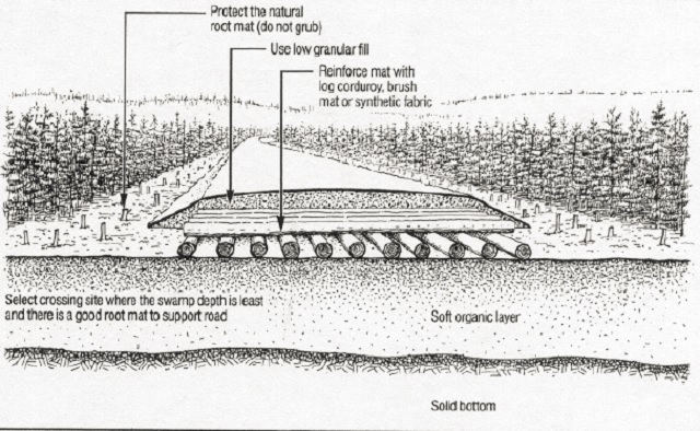
- Select a crossing location where there is a well-developed root mat supporting tree growth.
- Construction of swamp treatments in the winter has several advantages: it permits shear balding of stumps; heavier construction equipment can cross without getting bogged down or disturbing the root mat; and, construction can also proceed beyond the swamp without having to wait for the treatment to be completed.
- The most common swamp treatment method on access roads is to float the road fill on the natural root mat and minimize disturbance of the organic deposit. This is economical and, of the methods available, causes the least disturbance to the natural environment.
- If possible, limit fill depths over the swamp to 1.3 metres (four feet) or less.
- When fill heights (swamp loadings) cannot be limited to shallow depths, the swamp should be sounded with a steel rod to a solid bottom, so that future performance can be predicted.
- The root rant under the roadway should be protected from equipment damage. This can be done by: diverting through traffic to the edge of the right-of-way; close cutting or shear blading stumps instead of grubbing; and, using special wide-pad equipment.
- Avoid ditching in deep swamps unless absolutely necessary (say over one metre thick (three feet)).
- If the consequences of the natural mat failing are serious, use reinforcement materials such as geotextile fabric, geo-grid mats, brush mats or log corduroy.
- Fill used on swamp crossings, where the road is floated on the natural mat, should be free from large boulders or rocks that can puncture the mat.
- Provide frequent cross culverts, approximately every 300 metres (1000 feet), to ensure that surface water is equalized on both sides of the road. The culverts should be located where organic deposit thickness is least (thus less settlement). If culverts must be placed on top of deep organic material, it is best to leave their installation until late in the road construction, after some settlement has already occurred.
5.9 Graveling
This operation refers to the placing of sand and gravel materials to form the structural road sub-base and surface that supports the wheel loads.
A sand cushion may be used as a sub-base under the gravel surface if the underlying earth cut or fill materials are poor and of low strength.
The operation generally involves importing select material from a gravel pit nearby.
The equipment normally used includes front-end loaders, dump trucks, bulldozers, graders and back-hoes. Occasionally, crushing units, compaction equipment and water trucks are also used.
Good practices - graveling
- For the top 150 millimetres (six inches), a well-graded gravel with particle sizes evenly distributed between clay size and 25 millimetre (one inch) stones is preferred. It can be easily placed and compacted to the desired shape and will be more stable under load than a poorer quality material. Well-graded gravel tends to be erosion resistant, and its use will reduce the amount of road maintenance required.
- Shape, compact and crown the earth grade before placement of the gravel layer. This will minimize the amount of gravel needed and it will shed water seeping through porous gravel during wet periods.
- Avoid rutting by providing an adequate depth of gravel so the road will be able to carry the types of vehicles expected to be travelling over it during the times it will be needed.
5.10 Road maintenance
Access roads are maintained during the period of time they are required. The level of maintenance on an access road varies depending on its use at any given time. For example, during wood extraction operations, when numerous heavily loaded trucks are using a road, it is maintained to keep the riding surface very smooth. Later, if the road is no longer used for timber management, the road use may change. It can either be maintained at minimal levels for light recreational and other traffic uses or abandoned in an environmentally sound manner as described in Section 5.11.
The operations carried out for road maintenance can be broken into two main groups: routine and non-routine.
Routine operations include those day-to-day activities necessary to maintain the road for the traffic using it. These may include grading, snow plowing, and the maintenance of drainage by cleaning out blocked ditches and culverts.
Non-routine maintenance includes major repairs and restoration. Since roads gradually deteriorate with time, there is a periodic need to restore the condition of roads serving a long-term need. These roads may require major maintenance or re-construction to restore their original condition every ten to twenty years. Example operations falling into this category include: brush control with mechanical and chemical methods; replacement of gravel surfacing material; repair of major flood damage, and, replacement of sub-standard bridges.
If a road is not maintained, it should be abandoned in accordance with the use-management strategy for the road.
Good practices - maintenance:
- The usefulness and permanence of an access road depends on a good drainage system. Maintenance of drainage includes: regular inspection, clean-out of blocked ditches and culverts, grading to remove ruts and crowning of the road to shed water.
- During grading operations, loose materials should be brought back towards the center of the roadway to prevent the creation of berms that could channelize run-off down the road and erode the fill slopes.
- Nuisance beaver activity around culverts should be dealt with (refer to mitigation techniques in Section 7).
- Heavy equipment should not be used on roads during spring breakup, as this will lead to rutting, gravel contamination and possible erosion. The spring breakup usually corresponds with the period of half-load restrictions on secondary highways.
- In winter, sand is preferred over chemical de-icing salts. Where used, alts should be applied sparingly.
- Salt should be stored in dry sheds, to prevent infiltration into the water table.
- During snow clearing operations, snow banks should be winged back. This will decrease the time to melt the snow, and minimize spring saturation and erosion of the roadbed. It will also avoid creating an obstruction to wildlife movements.
- Remove roadside vegetation that shades the road, for safety (visibility) and for drying of the road. In erodible soils, do not expose the mineral soil during the brushing operation.
- Special mitigative techniques such as sediment traps and check dams should receive regular maintenance as long as they are needed.
- Calcium chloride may be used to stabilize the road surface and control dust problems. It should always be applied in accordance with the manufacturer’s recommendations.
- If herbicides are used for vegetation control, the person applying the herbicide should be licensed and a 10 metre buffer zone must be maintained adjacent to all water bodies. Mechanical means of vegetation control are usually preferable environmentally and are often economically competitive.
- Following timber management operations along the roadside, the roadway cross section should be restored by repairing damaged slopes, culverts and ditches.
5.11 Road abandonment
A Use Management Strategy is developed for primary and secondary roads as part of the Timber Management Plan or other planning process. The Use Management Strategy addresses the duration of use for the road and what actions are proposed when that use ends. The strategy may call for abandonment of the road when its original purpose ends. There are two forms of abandonment:
Physical Abandonment occurs when there is a deliberate act to render a road unusable by vehicular traffic. Physical abandonment could include taking steps which will minimize the environmental impacts of non-maintenance.
Natural Abandonment occurs when road maintenance has ceased, yet steps are not taken to prevent the use of the road by vehicles. With natural abandonment, no physical changes are made to the road.
In either case, abandonment should be carried out in an environmentally sound manner. Erosion and decay processes can lead to sediment problems in the area of water crossings.
Consideration should be given to regeneration of the road right-of-way to make the area productive for growing trees and to prevent erosion. This will lead to a more rapid re-establishment of natural conditions.
Erosion Control
Preventative measures can be taken to minimize erosion of the road fill and subsequent sedimentation in the watercourse. When a road is not maintained, frost and runoff will lead to loosening and erosion of fill and road surfaces. In the area of water crossings, the roadway slopes downhill, towards the stream. Water flowing down the road can erode the gravel surface and underlying fill. Preventative measures can be taken to minimize erosion of the road fill and subsequent sedimentation in the watercourse.
Water bars can be used to control surface water runoff and minimize erosion of the road surface and fill. Water bars are transverse ditches excavated across the road surface to intercept runoff and deflect it towards the ditches instead of flowing down the road surface. The outlet of a water bar should be extended into an area that is erosion resistant and that will filter out sediment. This control of runoff will prevent surface erosion and lead to quicker re-establishment of vegetation on the road.
- Remove roadside vegetation that shades the road, for safety (visibility) and for drying of the road. In erodible soils, do not expose the mineral soil during the brushing operation.
- Special mitigative techniques such as sediment traps and check dams should receive regular maintenance as long as they are needed.
- Calcium chloride may be used to stabilize the road surface and control dust problems. It should always be applied in accordance with the manufacturer’s recommendations.
- If herbicides are used for vegetation control, the person applying the herbicide should be licensed and a 10 metre buffer zone must be maintained adjacent to all water bodies. Mechanical means of vegetation control are usually preferable environmentally and are often economically competitive.
- Following timber management operations along the roadside, the roadway cross section should be restored by repairing damaged slopes, culverts and ditches.
There are two types of water bars, as shown on the sketch. One uses a log to divert water while still permitting passage by vehicles over it, the other would be used where there is no traffic on the road. Water bars should be spaced closer together in steeply sloping terrain. Spacing similar to that shown in Table 1 in Section 5.7 would be appropriate.
Removal of Structures
Water crossing structures that have required on-going maintenance to keep functioning, or which have deteriorate with time and may collapse into a waterway (for example untreated log bridges) should be removed when the road is abandoned. Structures built of permanent materials, such as steel or treated timber, that have been maintenance free, may be left in place.
Removal of structures will involve excavation of all materials below the high water mark. This may include bridge piers, stringers, decking, culverts and roadway fill. It is not necessary to excavate stable bridge abutments and erosion protection works. Often removal of piling from the river bed is not possible. Excavated material should be trucked away to a suitable disposal site at least 100 metres (350 feet) away from the water course. The banks and approach fills should be graded and trimmed to a stable angle similar to the adjacent natural river banks. The banks should then be provided with erosion control treatment if necessary to prevent erosion. Exposed soil on the river banks should have seed and fertilizer applied to speed re-vegetation.

6.0 Water crossings - good practices
6.l Introduction
Water crossings are locations where an access road crosses a natural water course having a defined channel. Any water crossing has the potential for significant detrimental impacts on water quality. Through good design, adherence to good construction practices and use of special mitigation techniques where required, disturbances during construction can be minimized and the site can be stabilized to prevent long term changes.
Water crossings have several characteristics in common:
- Selection of the water crossing location has a significant effect on the type of structure required and its cost.
- They require a properly engineered structure to safely carry the load.
- They usually involve water diversion and de-watering to allow construction in a dry condition, with foundations extending below the creek bottom.
- They are usually quite expensive.
- They can have a significant impact on fish habitat (e.g., spawning areas), water quality (e.g., turbidity) and fish migration.
- Protection and maintenance of aesthetics, fisheries habitat and wildlife habitat values are usually important considerations.
- Failure of water crossing structures can have serious consequences in terms of public safety, property damage, damage to the natural environment and inconvenience to road users.
This section is divided into the following four components:
- site selection and design
- fords and temporary bridges
- construction
- site clean-up
6.2 Site selection and design
A preferred site for construction is in a rapids section of a stream or river. These areas are often of high value for fisheries as spawning areas; as well, rapids are important for recreation. The area adjacent to a rapids may contain historical or archaeological material. Although these other values must be considered and protected, from an engineering viewpoint a rapids site offers the following advantages:
- Soils are usually resistant to erosion at high flow velocity.
- Foundation conditions are usually good, requiring less river bottom disturbance.
- The effects of upstream backwater, due to the constriction created by the crossing, will be limited to a short length of river.
- Water depths are usually shallow, and the encroachment for cofferdams to construct abutments or piers will be minimal.
Good practices - site selection and design
- Avoid poor crossing sites if at all possible. A poor site would be one where:
- Water depths at abutments and piers are great, i.e., over two metres (six feet).
- Soils are erodible and/or require expensive foundations to distribute the load, i.e., clay, silt or fine sand.
- Water surface widths are quite wide and flow velocities are low.
- Steep high banks or hilly approaches could make satisfactory road construction to the water crossing very costly.
- There are areas of bank instability, erosion or bends in rivers.
- Occasionally, islands can be used in a rapids or at waterfalls, to break a long span into two or more shorter spans. This also makes de-watering much simpler, since one channel can be completely closed at a time.
- If recreation or fisheries values are high in the area, the crossing location may have to be adjusted to a site that minimizes the impact on these values. For this reason, alternatives to the preferred site should be considered.
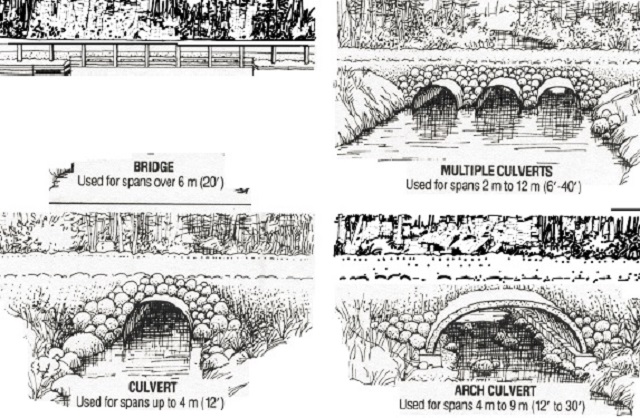
- Select a structure appropriate to the site. Commonly used alternatives are:
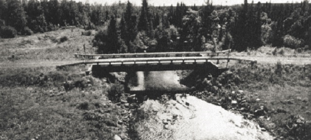
- Bridges with crib abutments, single span or multiple spans corporating piers in the river.
- Bridges with pile-supported abutments of single span or multiple spans.
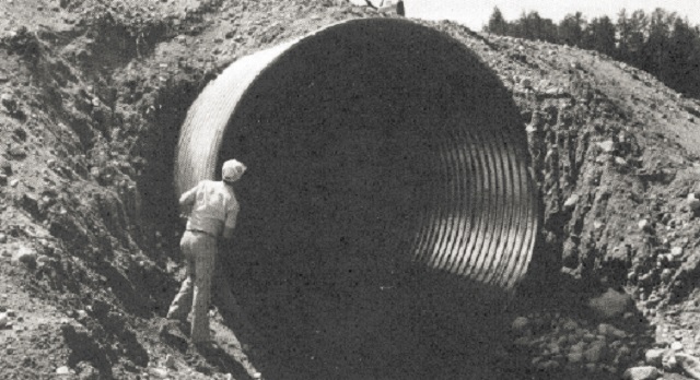
- Single corrugated steel pipe culvert or multiple csp culverts; these could be either circular pipe with couplers or field-assembled structural plate.
- Arch-type culverts incorporating two side footings and a corrugated steel arch to support the fill. This type of culvert leaves the natural streambed between the footings on either side.
- Box culverts with closed or open bottoms.
- For streams which are used for fish migrating or spawning areas, bridges or arch culverts, which retain the natural stream bottom and slope, are preferred over pipe culverts.
- The crossing should have structural capacity to carry the vehicle loads expected to cross it.
- The waterway opening size should be selected to minimize the risk of washout during the expected life of the structure.
- Hydrologic and hydraulic analyses should be in accordance with design procedures developed for Ontario use; refer to the Ministry of Transportation Drainage Manual. This conforms with review criteria under the Lakes and Rivers Improvement Act.
- The waterway opening size should be selected to ensure that upstream water levels will be acceptable, and that flow velocities will not be too high to prevent fish migration. Multiple smaller pipes will have lower flow velocity and may be preferred for fish migration purposes but may be more susceptible to blockage by ice or debris. The maximum number of culverts at a water crossing should be no more than three.
- Design mitigative techniques to accommodate any special requirements identified through the planning phase, or by Ministry staff during their review of the proposed construction.
- Culvert size should be selected so normal water levels rise no higher than half the diameter of the pipe.
- If possible, align the road so it crosses the waterway at right angles. Bridge abutments and piers should be aligned parallel to the direction of flow.
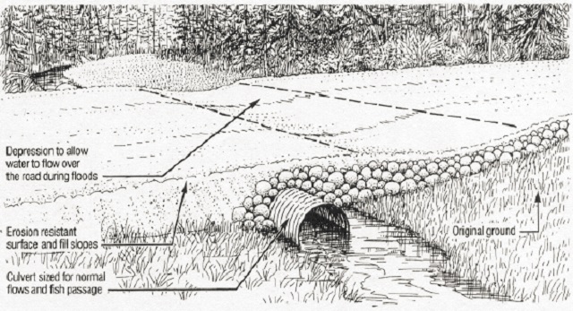
- It may be appropriate to place a dip in the approach grade to allow water spillage over the road if the pipe capacity is exceeded. This would also lower repair costs if a washout occurred.
- Select adequate lengths of culverts and use wing walls on bridges, to keep fill from spilling into flowing water, and to reduce maintenance costs.
6.3 Fords and temporary bridges
(a) Fords
Fording, or driving through a water course, may be an alternative used for access in limited specific circumstances. Sites favourable for use as a ford are those where:
- The streambed has a firm rock or coarse gravel bottom and where the approaches are both low and stable enough to support traffic.
- Use of the ford will be temporary and limited to low volumes of light vehicles such as initial access during clearing operations, or for mining exploration equipment.
The water depth should be less than one metre (three feet).
The natural carrying capacity of a stream bottom can be improved by constructing an underwater roadbed using log corduroy, coarse gravel, rock fill or gabions. If used, these materials should be set into the bottom so the driving surface will be flush with the stream bed to minimize erosion and to allow fish passage.
Good practices - fords
- Crossings should be at right angles to the stream.
- The road width should be not more than 10 metres (32 feet) wide and it should be well marked to be visible to drivers.
- If necessary, stabilize the approaches by using non-erodible material to 15 metres (50 feet) up the bank on both sides of the ford.
- Fords should be constructed and used during the driest times of the year.
- Minimize the amount of vegetation removed adjacent to the water crossing.
- Fish passage should be accommodated by maintaining a water depth of at least 200 millimeters (eight inches) or the natural stream depth at the location.
- Any material used within the stream to improve the crossing should be clean, non-erodible and non-toxic to aquatic life.
- Do not use the ford during fish spawning, incubation or migration periods.
- Equipment crossing the ford should be mechanically sound with no oil or gas leaks.
- When the ford is no longer required, restore the stream channel and banks to their original contours by removing material placed to construct the ford.
(b) Temporary bridges
Temporary bridges are constructed across waterways to serve a short-term purpose. Typical examples include access for bridge construction, and access for several months of timber harvest and extraction.
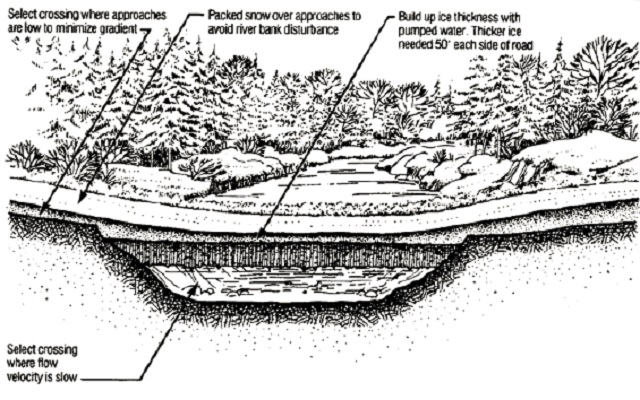
The crossings would not normally be designed to pass extreme flood events; they are usually intended to be in place for only a short period of time and then to be removed. They should have an adequate opening for expected flows during the time they will be in place without unduly backing up water. Ice bridges are constructed in the winter to take advantage of frost and ice in the waterways, to reach areas which may be otherwise inaccessible.
Bridges serving a short-term need may be constructed economically, using untreated log poles, however their strength diminishes with time as bacterial decay destroys the wood fibre. Untreated wood should not be used for bridges required for more than ten years of service. Temporary bridges usually span the water surface width, just above normal water level. Piers may be placed on the river bottom to break a wide river into short spans that log poles can bridge.
It is important that temporary bridges be removed when their use is finished. This is necessary since the waterway opening and the materials used for construction may be unsuitable for a permanent crossing.
6.4 Construction
in the dryis a key to proper installation.
Considering the effort that is normally invested in site selection and design prior to construction of a major water crossing, those responsible for on-site work should be aware of potential environmental impacts, and should take appropriate precautions to ensure those impacts under their control are kept to a minimum. Normally, this precaution adds little or no additional cost to the project.
In most cases, the satisfactory construction of a water crossing requires that flowing water be diverted away from work areas so that the structure can be constructed under dry conditions. Excavation for a bridge in the river bed, or placement of a large culvert, should not be done in flowing water. Rather, the work area should be isolated with a cofferdam or stream diversion.
Often there may be access to only one side of a water crossing, and it will be necessary to construct a means of temporary access to facilitate construction.
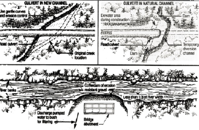
If a culvert is to be installed in a flowing stream channel, the water should be diverted around the work site during construction. Isolating the work site from the flow of water is necessary to minimize the release of soil into the water course and to ensure a satisfactory installation in a dry environment. Two methods of water diversion are commonly used for culvert installations: construction in the stream bed, or construction in a new channel, these are detailed in the sketch.
If a bridge is to be installed it is usually not possible to divert all of the flowing water, so partial diversions are constructed using cofferdams around the work areas.
Good practices - water crossing construction
- Cofferdams for bridge construction should not block more than one third of the waterway at a time.
- Provide sufficient waterway size for a diversion channel and temporary openings. Use erosion-resistant material, i.e., gravel fill with rip rap or geotextile lining.
- Restrict clearing width, and do not grub the right-of-way between the road and bush line within 100 metres (350 feet) of the waterway. Preserve vegetative cover as long as possible.
- Work in the river should be scheduled for the driest time of the year, usually July and August, unless this would create noise or visual impact problems for users of the waterway.
- Borrow material should not be excavated from the watercourse, except as part of a designed channel improvement.
- Equipment and materials should be stored well back from the water’s edge.
- Pump water should outlet into vegetative areas for filtering during de-watering operations.
- The number of equipment crossings in the river should be minimized by constructing a temporary bridge.
- Waste debris from grubbing should be hauled back and disposed of more than 100 metres (350 feet) from the waterway.
- Every effort should be made to complete water crossing construction as quickly as possible once the work begins. Limit the duration to minimize environmental impacts.
- Construction of water crossings must not take place during spawning/ incubation periods or major fish migration periods, as determined by the Ministry.
- Culverts should be installed in accordance with manuals available from the pipe manufacturers. To ensure satisfactory performance, particular attention should be paid to bedding, invert elevation, backfill material quality, placement of backfill in even shallow lifts on each side, backfill compaction and erosion protection.
- Culverts should be installed so the pipe has at least 10% of its diameter below the streambed. This will encourage formation of a shallow sediment layer in the pipe, and should ensure enough flow depth for fishmigration. During flood periods, the sediment will quickly erode. This practice will also minimize the chance of undercutting at inlet or outlet.
- Control materials on the job so that loose boards, nails and other debris will not enter the waterway and flow downstream. A log boom should be used downstream of the bridge site if there is a chance that debris (lumber) could fall into the water and be carried downstream.
- Do not clean concrete buckets, wheelbarrows, shovels in water bodies. Instead, wash them with hoses so that run-off is filtered through vegetation. Prevent the entry of lime, cement or fresh concrete into waterways.
- Oil-based treated timber (pentach-lorophenol, creosote) used below or near water level should be reasonably dry, without excessive surface oils. Timbers with oil base preservative treatments should be ordered early to allow air drying before use. Those with abundant surface oils should be used at the back of the cribs, against the approach fill.
- Field cuts and drill holes should be painted liberally with preservative to prevent decay; care should be taken to avoid contamination of the water by field-applied preservatives.
- If the project is a bridge replacement, remove the old stringers and decking. If reasonably possible, also remove foundation piers and abutments unless these may be useful to break up ice or protect against erosion.
- If culverts are founded on soft material, a granular bedding shaped with a camber should be provided, so that when settlement occurs, the pipe will function.
- For pier construction in open water, in which there are erodible river bottom sediments and where water quality must be protected, silt barrier curtains floating on the surface and anchored to the bottom should be installed around the work area.
6.5 Site clean-up
The final stage of construction is clean-up of the site. An extra effort on the part of construction staff can assist in the restoration of stable ground contours and protective vegetative cover, to prevent erosion and make the crossing more attractive in appearance to those who view it from the road or the water.
Considering the time and money spent on the physical structure to carry traffic over the waterway, a few days of effort on site restoration, while the resources are available, is a good investment for mitigating the long term environmental impacts of a water crossing.
Good practices - site clean-up
- Heavy rock rip rap material should be placed around abutment faces exposed to flowing water. This will minimize the possibility of undercutting and will help provide stability to the abutment.
- Rip rap should be placed on fill areas exposed to flowing water below the expected high water level. This includes areas around the inlet end of culverts.
- Place an erosion-resistant rip rap apron in the river bed downstream of the pipe, where increased flow velocities could cause serious scour. The apron should extend six culvert diameters beyond the end of the pipe and it should be sloped toward the centre of the channel to allow fish migration at low water flows.
- Restore or enhance fish habitat (spawning beds or aids to migration) if required by the Ministry; suggested methods are described in Section 7.
- All temporary imported material on the site should be removed, including any debris which has floated downstream of the crossing.
- Disturbed areas within 100 metres (350 feet) of a water body should be stabilized and re-vegetated to prevent erosion and to intercept sediment.
- River banks and fill slopes should be trimmed to a relatively flat angle that will be stable, i.e., 2:1 or flatter.
7.0 Mitigation techniques
7.1 Introduction
The environmental guidelines presented in the previous sections are recommended practice for all access road construction. In addition, there will be occasions when special mitigation techniques are needed to deal with a potentially serious problem, or to protect specific values that have been identified as needing protection from the impacts of construction.
This section is intended as a source of information for those involved in road construction who require technical detail concerning such mitigation techniques. The need to implement a special technique in order to prevent serious problems from developing could arise in situations such as the following:
- water crossings where there are important fish habitat, such as spawning beds, that could be destroyed if sediment levels are high.
- areas of concern identified during the planing phase.
- special values identified in advance that are to be protected from potential negative impacts (e.g. tourism).
- unexpected conditions identified during construction that require treatment or protection (e.g. erosion, archaeological material).
The subject is not treated here in an exhaustive manner; rather, commonly occurring treatments are described, and references are provided for those who require more information.
The techniques described are currently used in Ontario on access roads and, if properly implemented, can mitigate the specific impact of roadconstruction being addressed. The material covered in this section includes:
Even though special methods and measures exist for mitigating the impact of road construction, they may not be applied unless a need for them is apparent and a rational decision is made requiring their use.
Considerations for assessing the degree and extent of mitigation techniques required should include the following:
- compliance with standards and applicable legislation
- the value of the tangible and intangible resources to be protected
- the cost of supplying the protection
- the pre-construction conditions in the environment, i.e., natural water turbidity, natural erosion.
This document does not presume to determine when, where and at whose cost, mitigation techniques should be used; these are the perogative of those involved in the decision-making process preceding approval of road construction on Crown land. Whenever such choices must be made by those directly and indirectly involved in a project, their value systems, preferences, traditions and customs all have an effect on the ultimate decisions. Thus, one group might go to great lengths to protect and preserve a resource that would get little attention in another area. The considerations and criteria for special mitigation techniques should therefore be viewed by those making the decisions in light of their own perceptions of what is valuable, what is right and what is acceptable in the public interest.
Through the use of written description, illustrative sketches and photography, the objective here is to provide sufficient generic design information on the recommended techniques so as to minimize the need for further reference to other documents.
- erosion and sediment control
- control of beaver problems
- fish habitat protection
- aesthetic considerations
7.2 Erosion and sediment control
Erosion is the natural process of wearing away of the land surface by water, wind, ice and gravity. The construction of access roads exposes the mineral soil to the action of these forces, particularly erosion by water. Erosion rates from construction sites are much higher than the average rates in undisturbed areas. On a well-constructed access road, with appropriate use of mitigation techniques when and where required, restoration of stable erosion resistant conditions is possible within a few years.
7.2.1 Erosion and sediment control - causes of erosion
Erosion is essentially a two-part process. One part is the loosening of soil particles caused largely by raindrop impact. The other part is the transportation of soil particles, largely in flowing water. The principal factors influencing the existence or extent of soil erosion are precipitation (duration and force of loosening agent), soil characteristics (susceptibility to erosion), topography (duration and force of transporting agent), and ground cover (protection). Any erosion control treatment must address at least one of these factors to be effective. A brief explanation of each factor will aid in understanding the mitigation techniques suggested.
Precipitationis the driving force behind erosion. Raindrops falling on exposed soil dislodge individual particles. The duration, intensity and raindrop size all influence the erosive force exerted by rainfall on the soil.
Soil characteristicsthat affect erosion include permeability and stability. Soil porosity affects the infiltration of rainwater into the soil and its capacity to store water before overland flow begins. Soils exposed to compaction by equipment and vehicles driving over them will have less porosity than undisturbed soils. Soil stability is the resistance of the individual particles to displacement and transport under the action of rainfall and flowing water. Generally coarse soil particles, soils with a well-graded mixture of particle sizes and cohesive clay soils are more stable than fine single-particle sized soils.
The volume of water flowing over a soil and its velocity are determined by the topographyof the area. Important variables are the upstream drainage area and the slope of the ground at the particular point. Roadside ditches on long steep slopes are especially vulnerable to erosion because the drainage area can be large, and flow velocities can be quite high as the runoff builds up momentum.
Vegetationis one of nature’s methods of erosion control. Ground cover protects the mineral soil from the erosive action of falling raindrops and flowing water. It also slows the velocity of runoff, it holds soil particles in place and it maintains the soil’s capacity to absorb water.
7.2.2 Erosion and sediment control - design principles
The principles of erosion and sediment control design are based on simple common sense. Erosion control is done to prevent or minimize the erosion of soil. Sediment control is the trapping of suspended soil particles being transported downstream in flowing water to prevent their discharge into the aquatic environment of a stream. Erosion control is obviously the only effective long-term solution, whereas sediment control is a short-term remedy to minimize the impact of unavoidable erosion that does occur during the construction period.
The eight principles of erosion and sediment control are:
- Fit the road to the terrain
In the planning, design and construction of access roads this means: avoid erodible soil sites; follow the ground contours as much as possible; and, do not construct deeper fills and cuts than the geometric road standard requires. - Minimize the duration of soil exposure
Limit the duration of exposure by scheduling the work so construction coincides with the dry season and complete grading operations soon after the grubbing operation exposes the soil. - Retain existing vegetation where feasible
Very little erosion occurs on soil covered with undisturbed natural vegetation. Re-establishment of comparable coverage after construction can take a long time. Limit the soil exposed by grubbing to the area where construction will actually occur. - Grade disturbed soil to a stable slope
A slope which is inherently unstable will be unable to develop a satisfactory vegetative cover until it has eroded back to a stable angle of repose. For most soils encountered in access road construction in Ontario, this means cut and fill slopes should be shaped to a slope between 1.5 and 2.0 horizontal to 1.0 vertical. - Encourage re-vegetation
A properly re-vegetated soil will be protected from erosion indefinitely without any need for human attention. Re-vegetation will occur naturally if the slope is stable. Re-vegetation can be encouraged by leaving some organic material mixed in the uppermost soil layer and/or by seed and fertilizer treatments. - Divert runoff away from exposed soil
Surface water drainage that would naturally flow over the exposed soil can sometimes be diverted away from the area. Runoff collected in roadside ditches should be diverted to an outlet off the right-of-way. The frequency of outlets and cross-drains to carry water from upstream to downstream side of the road should be designed to fit the ground slope involved. - Keep runoff velocities low
The energy of flowing water increases with the square of the velocity. Thus, less erosion will occur if the water is moving slowly. Flow velocities can be kept low by lining erodible soils with rough surfaces such as vegetation, rip rap and brush. The construction of check dams in ditches will break the flow momentum and reduce velocities. Flattening the steepness of a slope and creating roughness in the flow path of water will reduce velocities. Ditch sizes should be selected to handle the expected runoff from precipitation - this means that larger ditches are needed to handle runoff from larger drainage areas. - Trap sediment before it can cause damage
Some erosion during construction is unavoidable. In order to prevent sedimentation of streams it is desirable to trap sediment on land before it reaches the aquatic environment. The most common method used on access roads is the diversion of runoff into the adjacent forest floor where suspended soil particles are filtered out as runoff flows through the surface vegetation and litter. The placement of a brush barrier made with slash debris on the lower slope area can also create a filter. Sediment traps can be made by excavating a depression downstream of the sediment source that will pond water so suspended soil can settle out. Another method of trapping sediment is to filter the runoff from an area through asilt fence
made of geotextile fabric or straw bales. The water passes through but silt and sand is filtered out.
7.2.3 Erosion and sediment control - mitigation techniques
The technology for erosion and sediment control is well developed. Accepted, proven techniques are described in detail in the Ministry of Transportation Drainage Manual and The Erosion and Sediment Control Handbook (see references). In this section, techniques which are particularly suitable for use on access roads in Ontario have been selected for detailed presentation.
Flexibility in the construction of access roads allows individuals the opportunity to exercise innovation in mitigating the effects of erosion and sediment in a variety of ways. Relatively simple and inexpensive techniques developed in a local area can be just as effective as more expensive methods found in a textbook.
The techniques described below are:
- rip rap
- slope modification
- re-vegetation
- check dams
- sediment traps
- brush barriers
- silt fences
- a forest floor filter
Each of these techniques is based on one or more of the principles described previously. The implementation of economical control measures, when and where required, will reduce the environmental damage caused by erosion and sedimentation. The effectiveness of the mitigation techniques described may be increased by combining more than one method. For example, the use of a brush barrier, together with seed and fertilizer, will be more effective than either method on its own.
Erosion control using rip rap
Locations:
Rip rap may be used on any exposed mineral soil subjected to flowing water where the velocity of water flow, seriousness of erosion, steepness of slope, or material type, prevents satisfactory establishment of vegetative cover. Examples could include:
- Ditches in erodible soils on a slope of more than 3% could result in flow velocities that will erode and transport ditch bottom material.
- A fill slope at the entrance to a culvert, where the channel constriction causes high flow velocities during flood flow that could erode the road fill and cause washout.
- A river bank in the vicinity of a bridge or culvert where soil erosion could undermine the bridge or its approaches.
Although all water crossings will require rip rap erosion control to some extent, other applications for rip rap may arise during construction of the road.
Function:
Rip rap lining slows down the flow of water. This reduces the erosive forces acting on the soil, and provides a lining of competent material too large for the water to displace. The reduced flow velocity encourages water infiltration into the ground and vegetative growth between the rip rap particles.
Design and Construction Information:
Rip rap linings can be made to withstand most velocities if the proper size of rock is selected. The construction sequence would include surface grading, possible placement of a filter layer (either geotextile or granular material) and placement of the rip rap layer.
Preparation of the surface to receive the rip rap layer is important. Slopes should be shaped to a steepness no greater than 2:1.
Filters are required if there will be groundwater emerging from the soil under the rip rap layer. The geotextile filter placed under the rip rap can be woven or non-woven material of relatively light weight. Sand or gravel may be used as a filler.
Blasted rock fragments, available from rock cut areas, make the most suitable rip rap material because of their rough angular shape and because they can be made to the desired particle size.
If rock cut material is not available, boulders from a borrow pit may be used. They will tend to roll on each other and a flatter slope may be necessary than would be the case if blasted rock were available.
The desirable particle sizes for use in access road construction are as follows:
| Application | Range or Sizes | Median Size |
|---|---|---|
| River Bank Protection (2:1 Slope or Flatter) | 50 mm to 500 mm (2 in to 20 in) | 200 mm (8 in) |
| Roadside Ditch Lining (<5 % Slope) | 10 mm to 200 mm (.5 in to 8 in) | 100 mm (4 in) |
| Roadside Ditch Lining (>5% Slope) | 10 mm to 400 mm (.5 in to 16 in) | 150 mm (6 in) |
The rip rap material is placed by machine, usually a backhoe. It is levelled to a uniform layer thickness approximately one and a half times the median particle size. In a ditch bottom lining, the protection should extend up the side slope and backslope above the expected high water level in flood.
Disadvantages:
Although quite effective, the treatment is very expensive, and in some areas where there are no rock cuts or suitable pit boulders available, its use may be impractical.
Approximate Cost (1987 dollars):
The cost of this treatment depends on the availability of suitable material. The quantity of area to be treated also has an important effect on the unit costs applicable to a specific site.
The following are approximate figures:
If there are rock cuts within 20 km (blasted rock available free): $12 per square metre ($10 per square yard)
If there are no rock cuts and rock must be quarried: $24 per square metre ($20 per square yard)
If there are no rock cuts and boulders are available within 20 km: $24 per square metre ($20 per square yard)
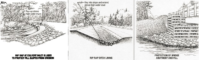
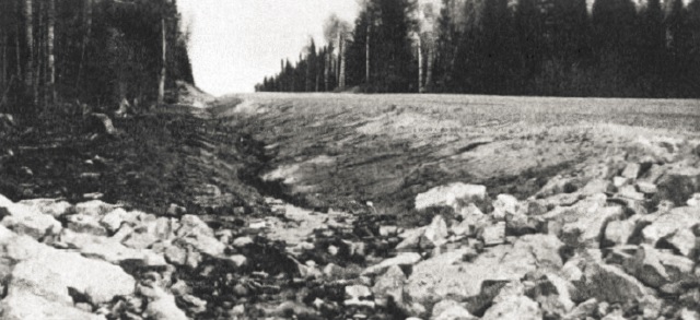
Erosion control using slope modification
Locations:
Slope instability and erosion of earth cuts and fills can be reduced by flattening the gradient.
Function:
A cut or fill slope constructed too steeply, steeper than the soil’s natural angle of repose, will mean that the surface soil particles are inherently unstable and satisfactory re-vegetation would not be possible. Surface roughening, using special grading techniques, can reduce the amount of runoff travelling down-slope, reduce the flow velocity, increase infiltration, and intercept some of the sediment before it reaches the toe of slope.
Design and construction information:
(a) Slope Flattening:
Graded slopes, such as earth cuts and fills, should not be too steep - preferably 2:1 (two metres [six feet] horizontal to one metre [three feet] vertical) or flatter. The chance for successful re-vegetation will be greater on gentler slopes. Flattening a steep slope involves adding more fill, or taking out more cut material, than would otherwise be the case, to create a more stable angle. For example, an earth cut slope in fine sand material excavated at 1:1 would likely be unstable and subject to a serious erosion problem.
Flattening the same slope to 2:1 will result in better stability and quicker attainment of re-vegetation. The best time to do this work is during initial rough grade construction. Although a steep cut may be trimmed back economically, it is very costly to flatten an existing road fill that is too steep. It is best to construct stable fill slopes from the bottom up.
Once a stable angle of repose is reached, there is little benefit in further flattening; this will just increase the area of soil exposed to erosion.
Changes in slope angles should be rounded in shape to reduce erosion potential and to blend with the natural landscape. Rounding is particularly important at the top of cut excavations.
(b) Surface Roughening: Graded areas can be roughened in a variety of ways. One of the simplest is to drive a bulldozer or other tracked machine up and down the slope. This process, called track walking, leaves a pattern of tread imprints parallel to slope contours. The tread indentations are ideal for trapping seeds and encouraging plants to become established. The tracks also slow the velocity of runoff.
Disadvantages:
These methods may not be the most economical for the road builder since more material has to be moved to create flatter cut and fill slopes.
Approximate Cost:
The cost of this treatment is reflected in the additional material that must be excavated and placed in fills. The cost on any particular access road depends on the depth and length of cuts and fills. It should be recognized that a steep, inherently unstable slope, will continue to regress and flatten naturally until the stable angle of repose for the soil and moisture conditions is reached. This means that if not properly shaped initially, the road cut or fill will create maintenance problems until it stabilizes. In this regard, proper initial grading is usually more economical in the long run.
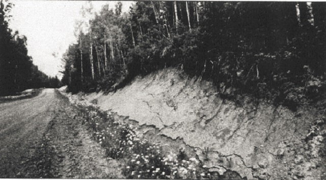
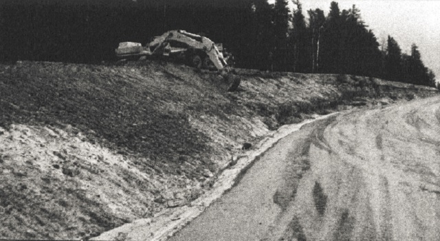
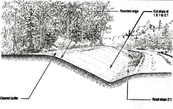
Erosion control using re-vegetation
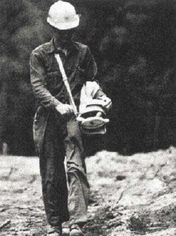
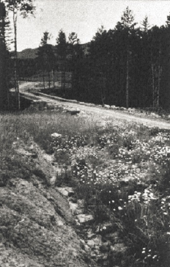
Locations:
Seeding, to re-establish vegetation, is often done in the area of water crossings. It may be used in other areas, for aesthetic reasons, to limit the time soil is exposed to erosion, or to establish a growth of acceptable grasses in preference to brush which could obstruct sight lines.
Function:
Seeding advances the time for re-vegetation by ensuring that sufficient seed is on the exposed soil at the end of construction. Quick re-vegetation will minimize erosion by providing suitable protection of mineral soil against erosion. With proper selection of the seed mixture, a specific vegetative cover with desirable properties for an area can be used.
Design and Construction Information:
Re-vegetation normally consists of the application of grass and legume seeds, and fertilizer to provide nutrients for growth. A wide variety of seed is available (see recommendations below). Mulch, although not absolutely necessary, will increase the odds of successful re-vegetation by holding the seeds in place until germination can occur. Mulches used in Ontario include straw, shredded paper, wood chips, matting and slash debris.
Criteria to be considered in the selection of seed mixture include:
- complete soil protection
- fast growing
- easy to plant
- adapted to the soil type
- adapted to local environment
- regrowth in subsequent years
- available commercially
- low maintenance
- low cost
The mixture should be selected to meet as many of the above criteria as possible. Having a variety of species, rather than a single plant type, will increase the chances for success.
The time of planting is important. The best time to plant is when temperatures, moisture and sunlight are adequate - usually in spring and fall.
The key factor in seeding is to get the seeds evenly distributed and in contact with the soil. Best results are obtained when seeds are covered with a shallow layer of soil, about 10 millimetres (.5 inches) in thickness. Low cost seeding of small areas, such as water crossings, can be done using hand broadcast seeders.
Hydraulic seeding and mulching is efficient for larger areas. It is a one step process for spraying a slurry of seed, fertilizer, wood fiber mulch and water. The critical factor in hydroseeding is the ability of the fiber to adhere to the soil and hold the seed in place during rainfall and wind.
Fertilizer is essential to the establishment of vegetation, particularly where organic soil has been removed in grubbing. The key elements are nitrogen, phosphorus, potassium and sulphur. The amount and type of fertilizer depends on local soil and water conditions.
The use of shrubs, trees and other live plantings along water ways or lake shores may be desirable for aesthetic or other purposes, such as shading. Techniques are also available for using live and dead plant material for erosion and sediment control. Such techniques are known as bio-engineering; these are characterized by low material and equipment costs, but they are quite labour intensive. Information on these methods is contained in the references listed in Section 9.
Sandy, infertile sites with little topsoil
| Materials | Per Hectare | Per Acre |
|---|---|---|
| Norlea Perennial Rye Grass | 25 kg. | 22 lb. |
| Birdsfoot Trefoil (inoculated seed) | 32 kg. | 28 lb. |
| Canada bluegrass | 20 kg. | 18 lb. |
| Tall fescue | 18 kg. | 16 lb. |
| Creeping red fescue | 10 kg. | 9 lb. |
| Creeping foxtail (coated) | 10 kg. | 9 lb. |
| Biljart hard fescue | 5 kg. | 5 lb. |
| Alsike Clover | 5 kg. | 5 lb. |
| 8-32-16 standard fertilizer mixture | 350 kg. | 310 lb. |
| 0-40-0 super phosphate fertilizer | 200 kg. | 180 lb |
| 0-0-60 muriate of potash | 200 kg. | 180 lb. |
Loamy to clayey, more fertile
| Materials | Per Hectare | Per Acre |
|---|---|---|
| Alsike clover | 20 kg. | 18 lb. |
| Creeping red fescue | 55 kg. | 50 lb. |
| Canada bluegrass | 27 kg. | 24 lb. |
| Perennial rye | 15 kg. | 14 lb. |
| White clover | 3 kg. | 3 lb. |
| 8-32-16 fertilizer | 350 kg. | 312 lb. |
Source: Ontario Ministry of Transportation, Maintenance Branch.
Disadvantages:
Stimulation of re-vegetation by seed and mulch applications is quite expensive and, except near water courses, the benefits of quicker re-vegetation than would occur naturally may not justify its use on most access roads.
Approximate Cost (1987 dollars)
For broadcast seeding: $1,150 per hectare ($460 per acre)
For Hydroseed and wood fibre mulch: $3,000 per hectare ($1,200 per acre)
Erosion control using check dam
Locations:
Check dams are used in ditches to create an overflow weir that slows down velocity, thus reducing ditchline erosion. They may be either temporary, until vegetation is established, or permanent. The drainage area of the ditch being protected should not exceed four hectares (10 acres).
Function:
Check dams prevent channel erosion by maintaining low flow velocities and catching sediment. Runoff is stepped down the sloping ditch at check dam locations where erosion resistant material is provided.
Design and construction information:
Check dams can be constructed using virtually any material available on site, such as logs, shot rock, boulders, sandbags, gabions, wood planks or other erosion resistant material.
They are constructed by placing selected material across the ditch channel normal to the flow. It is important to properly embed the dam to prevent undercutting by flow under the dam.
The weir size must be adequate to prevent washing around the edges through the native soil.
The maximum height of a check dam should be less than 600 millimetres (two feet) and the centre should be at least 150 millimetres (six inches) lower than the outer edges. The spacing of check dams in a ditch should be close enough to control flow velocity.
Disadvantages:
Close spacing on steep grades is required. Frequent clean-out is needed for best performance. Unless properly designed and keyed at the side and bottom, erosion around the edges may occur. If the dam washes out, it may cause more sedimentation downstream than would have occurred if the check dam had not been used.
Approximate cost (1987 dollars):
Assuming suitable boulder material is available within a 10 kilometre (six mile) haul, an approximate cost would be $200 per dam.
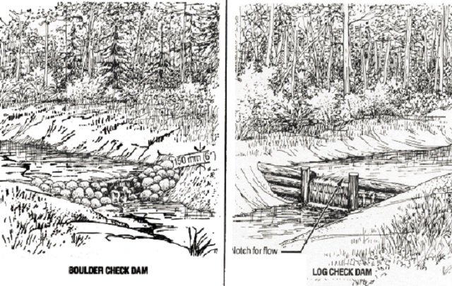
Sediment control using sediment traps
Locations:
Sediment traps are used downstream of erodible soil sites, such as earth cuts, to keep sediment from flowing downstream and entering water courses. The trap should be located close to the source of sediment, preferably in natural low areas or in pockets used for borrow extraction. They are effective for drainage areas less than two hectares (five acres). A sediment trap should not be located in a water course.
Function:
The traps reduce the flow velocity as water passes through the small pond. This allows larger suspended material, such as sand size particles, to settle out.
Design and construction information:
The trap is constructed by excavating a hole in the ground or by creating an impoundment with a low-head dam.
The trap size and the spacing between traps should be selected so that sediment from expected erosion areas fills the traps about the same time that vegetation is re-established to prevent further erosion. Otherwise, periodic re-excavation of deposited material is needed. The length to width ratio should be 2:1 or larger. A typical trap for a two hectare (five acre) area may measure four metres (15 feet) in length by two metres (six feet) wide by 600 millimetres (two feet) in depth.
The outlet end of the sediment trap should be adequately protected against erosion since it acts as an overflow weir.
For areas larger than two hectares (five acres), fairly sophisticated structures known as sediment ponds may be used. Design techniques, formulas for estimating sediment loads and recommended pond sizes may be obtained from the references in Section 9.
Disadvantages:
Sediment traps do not eliminate all sediment and turbidity; they only remove large particle sizes. They become ineffective when filled with sediment. The trap is a temporary measure until erosion stops.
Approximate Cost (1987 dollars):
If the soil material within the right-of-way is suitable for constructing fills, a sub-excavation to provide a sediment trap will not cost anything; rather, it will provide an economical source of borrow. If the roadside material is unsuitable for use in fills, the trap described above may take a backhoe about one hour to construct and trim, thus costing about $100.00.
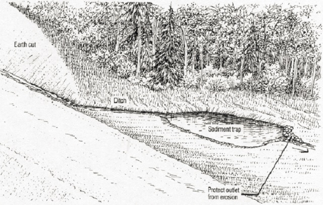
Erosion control using brush barriers
Locations:
Brush barriers can be used at any location where sediment in surface water requires filtering. The maximum slope length upstream of a barrier should be no more than 30 metres (100 feet). A typical treatment may be specified for the fill slopes on both sides of the road approaching the water crossing and extending about 100 metres (350 feet) on each side of the waterway.
Function:
The brush barriers filter the water runoff by reducing flow velocity and trapping sediment in the branches and limbs of the brush pile. Detailed comparative studies on U.S. Forest Service access roads have monitored the effectiveness of this method. A conservative estimate of the sediment trapping efficiency of the windrows is 75 to 85 %. The brush barriers also serve to protect the fill slopes from erosion.
Design and construction information:
This sediment control technique utilizes natural materials, provides immediate protection, requires no additional disturbance width, is aesthetically acceptable in remote areas, and is inexpensive. The material used includes logs, brush and other slash debris.
Construction is accomplished in two phases. First, during clearing, suitable material is stockpiled along the edge of the cleared right-of-way. The material requirements include large anchor logs and slash debris consisting of tops, limbs and brush not exceeding 150 millimetres (six inches) in diameter and four metres (12 feet) in length. Stumps should not be included.
The location of stockpiles should be planned so they are not in the way of road construction or wood salvage operations, and so they will be readily accessible to construction equipment sitting on the completed road. The stockpiled slash should not block drainage courses.
The second phase occurs after earth fill construction is completed, a large cull log is moved from the stockpile and placed in position at the toe of the fill, parallel to the direction of the road. It is anchored in position by placing it against stumps, rocks or trees. Stockpiled slash is then placed on the fill slope above the cull log. The windrow is compacted by tamping the slash with the backhoe bucket. This produces a relatively dense windrow embedded in the fill surface. It is important that the slash be embedded to prevent flow under it.
In addition to use on the toe of slopes, slash debris can be used to reduce erosion and sediment transport from any area of erodible soil. Slash debris can be spread over the exposed mineral soil and then trampled into place using tracked construction equipment.
Disadvantages:
Some people view the presence of logs and brush along the roadside as being aesthetically offensive. If not properly anchored and embedded in the slope, the brush material may be ineffective and could come loose to block ditches or culverts.
Approximate cost (1987 dollars):
Studies have shown that a track-mounted Caterpillar 235 backhoe was able to construct windrows at a rate of 52 metres per hour (170 feet per hour) (from Cook and King). This would equate to $0.65 per lineal foot treated. This figure does not count the cost savings in not having to dispose of the brush in push-outs.
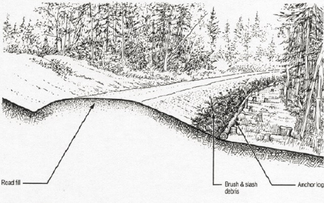
Sediment control using slit fences
Locations:
Silt fences are installed to collect sediment from small areas during construction. Typically, they would be built at the toe of an embankment slope, along the bank of a sensitive stream, or at the downstream end of an erodible earth cut area. The maximum slope length behind the barrier should be no more than 30 metres (100 feet), and it should be no steeper than 2:1.
Function:
Silt fences act like a strainer; silt and sand are trapped on the surface of the fence while water passes through. Silt fences also reduce the velocity of sheet flow and thereby induce the deposition of sediment.
Design and construction information:
Silt fences are relatively inexpensive filtering devices in the form of permeable or semi-permeable fences or dams.
They may consist of woven geotextile filter fabric or straw bales placed in the path of flowing water.
The fence should be installed before earthmoving operations commence.
If one fence fills with sediment another can be built behind it.
Construction of a silt fence with geotextile fabric includes the following steps:
- Vertical wood posts are embedded in the ground at a spacing not greater than three metres (10 feet).
- Geotextile fabric is fastened on the upstream side of the posts. To prevent undermining, the geotextile must be anchored in a trench 100 millimetres (four inches) in depth and width upstream of the barrier. Details on silt fence construction using straw bales can be found in the references.
Disadvantages:
Silt fences are flimsy, lightweight structures suitable for filtering small volumes of water flow, therefore their use is limited to small drainage areas. They should not be placed across a drainage path that carries high-volume or high velocity flow where washout could occur. Failure of a silt fence due to improper installation may allow a considerable quantity of accumulated sediment to pass down-stream. Straw bales are difficult to obtain in many areas where access roads are constructed and they only last from three to six months.
Approximate Cost (1987 dollars):
A silt fence, 10 metres (30 feet) in length, may require four wood posts and about 20 square meters (200 square feet) of geotextile fabric. The estimated cost for materials and labour costs would total about $100.00.
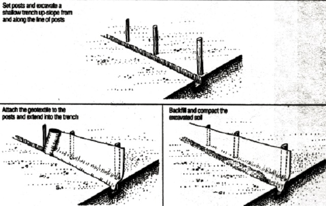
Sediment control using forest floor filter
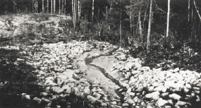
Locations:
The forest floor adjacent to the right-of-way provides a natural sediment filter at virtually any location on the downstream side of the road. Use of this natural filter is particularly important near water crossings, so that turbid runoff does not flow down the ditch and stream banks into the water directly.
The drainage area upstream of the diversion berm should be less than two hectares (five acres).
Function:
The natural forest floor, with its litter and vegetative material, can be used to serve as a filter medium to trap sediment before it reaches a water course.
Design and construction information:
This treatment may require construction of an earth diversion berm across the ditch line, and excavation of a channel to carry water to the edge of the right-of-way. A diversion berm is different from a check dam because water is diverted out of the ditch and not allowed to flow over the berm. Where used, it is important to check that the water will, in fact, drain away from the right-of-way at a slope of at least 1%. Berms should have a top width and height of at least 500 millimetres (20 inches) and side slopes of 2:1 or flatter. Since the diversion berm will be redirecting flowing water, the upstream surface should be resistant to erosion from the expected flow velocities.
The recommended spacing between ditch outlets depends on the slope of the ditch and the erodibility of the soil; refer to Table 1 in Section 5.7.
The length of forest floor required for effective filtering and sediment entrapment is generally recommended as 30 metres (100 feet) for slopes less than 15 %, and up to 90 metres (300 feet) on steeper slopes.
Disadvantages:
Ditch channel, berm size and outlet channel must be of adequate size to handle expected flow, including flood flows. If not properly sized, the berm will overtop and flow will continue down the ditch line.
Approximate cost:
A nominal cost may be incurred to construct the berms and provide off-take channels, however this would be offset by a savings in downstream ditch size and elimination of the possible need for erosion protection.
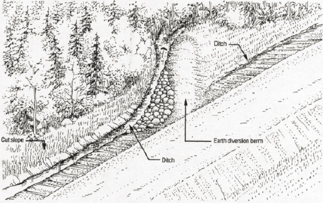
7.3 Beaver Problems
Road culverts are ideal sites for beavers to construct dams for backing up water and creating habitat. Blockage of culverts by direct beaver activity, and the failure of beaver dams that cause the sudden release of water, have led to many road washouts. There are two types of action that may be taken to minimize the problem:
(a) Special Design Techniques:
In new construction taking place in beaver areas, the use of larger culvert pipe diameters will tend to make dam construction more difficult. Battery operated electric wire fences, such as those used for farm animals, have also been successful in discouraging beaver activity by giving them an electrical shock at the culvert inlet.
Devices can be installed upstream of the culvert inlet to prevent dam construction in the pipe itself. Bed springs have been used for years as a screen. More sophisticated attachments include a wire mesh culvert protector that is a three metre (10 foot) upstream extension of the culvert, made of heavy wire mesh rolled to the diameter of the culvert. Patented culvert attachments are also available from several suppliers. These devices attract the beaver to build in a certain location where periodic removal of debris is not as difficult as from inside a pipe. Some of the attachments must be removed to ensure free flow of water during flood periods. As long as the beaver is active in the area of the culvert, maintenance will be required.
(b) Beaver Removal:
If the above methods are unsatisfactory or undesirable, it is recommended that, through the Ministry, the services of the local licensed trapper be enlisted to remove the beavers or to keep the culvert area clear. Beaver, as fur bearers, are protected under legislation; their removal is subject to factors such as seasons, quotas and license requirements involving trappers. If beavers are trapped outside of peak season, the fur quality and its value will be reduced; thus, some compensation may have to be paid to the trapper. Removal of beavers and breaching of beaver dams often proves to be a temporary solution since other beavers in the area may move in and take over if the habitat is favourable.
7.4 Fish Habitat
Good water crossing construction practices should protect fish spawning areas. However, if erosion and sediment control measures have not prevented silt from damaging spawning beds, then the rehabilitation of fish habitat may be required. This may require restoration of a degraded spawning area to a condition that sustains the incubation of fish eggs.
In other cases, spawning areas may be affected by the physical presence of a water crossing, and thus some habitat development may be required. This may involve the creation of new spawning beds in areas where they did not previously exist. Sometimes, if spawning areas are limited, the construction of a water crossing may provide the opportunity to create additional spawning areas.
There are two main techniques used to rehabilitate and develop spawning areas. One technique is to clean spawning gravels with high pressure fire hoses, beginning at the upstream end and working downstream, pushing silt and dead algae ahead of the water discharge.
The other technique is to add suitably sized rock to create spawning areas using the following guidelines:
- For walleye and white suckers (spring spawners), and lake trout and whitefish (fall spawners), choose rubble or clean boulders 75 to 250 millimetres (three to ten inches) in diameter, deposited to a depth of three to four layers, ensuring that there will be at least 200 millimetres (eight inches) of water above the rocks during the spawning period.
- For rainbow trout and brook trout, use 25 to 75 millimetre (one to three inches) and 6 to 50 millimetre (one quarter to two inch) sized gravel respectively, placed several layers deep.
- Larger rocks - 250 to 750 millimetres (10 to 30 inches) in diameter, depending upon water velocities, can be placed about two metres (six feet) apart. This creates resting areas or instream cover for spawning fish, and also creates back eddies for egg deposition. For more information on creating spawning areas, contact the Ministry.
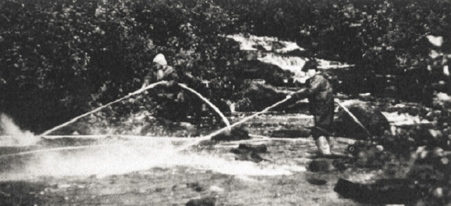
Streams with suitable spawning and rearing areas will probably be fish migration routes as well.
The use of bridges or arch culverts is recommended for fish migration routes where the roughness of a natural stream bed is desirable for reducing flow velocity. In some cases, the same effect can be achieved in pipe culverts by installing a layer of stone, provided the stones are large enough not to be moved by the design flood. Larger rocks, one to ten metres (three to thirty feet) apart, can provide resting places for fish, providing the rocks are alternated from side to side to prevent long runs of fast water along the side.
The greater roughness of corrugated interiors may be an advantage for fish passage, and for other situations where barrel or outlet velocities must be reduced.
Bolt connections should be installed with the bolt head on the culvert interior to prevent fish being damaged on the sharp nut and bolt end.
Culverts on fish migration routes should not unduly hinder the passage of fish during flow conditions likely to prevail at the time of migration. The corresponding discharge, of or fish passage design flow, is applied to the culvert after it has been sized to satisfy the normal flood flow criterion. If migration and the annual flood period are likely to coincide, as for spring spawners such as walleye and suckers, the simplest approach to determine of is to use mean monthly flow estimates for the May-June period. This allows for the fact that fish normally wait for a day or two after the flood peak has passed.
If migration is unlikely to coincide with the maximum annual flood period, as for fall spawners such as brook trout and whitefish, Qf should be assumed to be equivalent to 30% of the mean annual flood discharge. If an average flow depth at the time of migration can be established, Qf may be calculated by multiplying the average flow depth (d) by the average width (B) and the estimated average velocity (V) in the stream cross-section, i.e. Qf = BdV. (Examples are given in Chapter B, Design Flood Estimation for Small Watersheds, Ministry of Transportation Drainage Manual).
It is recommended that fish should not be delayed longer than three days on the way to their spawning grounds, but this depends on where the culvert is located on the migration route.
Not all fish have equal swimming ability. Figure A indicates that trout can handle higher velocities than pike. Swimming ability is also based on fish size. Normally larger fish can handle higher velocities better than smaller ones, but smaller fish may be able to use the zones of lower velocity water near the bottom or sides in culverts; this factor may obscure the relationship between swimming ability and fish length. The graph shown as Figure A may be applied to culverts using the mean water velocity at the fish passage design flow (Qf) and the culvert length as the swimming distance.
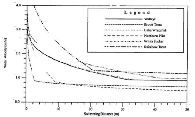
Slope is the most important factor determining water velocities in culverts at lower flows. Keeping the culvert gradients as flat as possible will encourage fish migration. If the fish velocity criterion cannot be met by modifying the culvert design, baffles, which create resting areas at intervals along the culvert, can enable fish to pass through. Offset baffles are the most commonly used type: these are described in the Ontario Ministry of Transportation Drainage Manual (Chapter D, Sec. 2-10.2).
For design information on culvert fishways, refer to the references listed in Section 9.
7.5 Aesthetics
Although the scope of these environmental guidelines is intended to deal primarily with the physical environment affected by access road construction, a brief discussion of aesthetics is warranted because appearances affect people’s attitudes.
In the construction of highways and streets in Ontario, aesthetics represent an important consideration. These roads are part of the environment in which people live; many spend a measurable proportion of their time travelling on them. Aesthetics, or the appearance of a roadside environment, is a personal subjective matter.
Traffic volumes on the highway system are relatively high when compared to access roads in the bush. Average traffic on an access road constructed for timber management activities might reach 50 vehicles per day during the most active harvesting period, and drop to perhaps five vehicles per day after harvesting. For this reason, the benefits of improved aesthetics on access roads do not usually justify the high cost of landscaping the roadside environment to make it pleasing to the eye.
Current practice is to identify, during the road planning phase, those roads and work areas that should be constructed to a higher aesthetic standard of appearance than is considered necessary to protect the physical environment. For example, a major access corridor that will carry long-term, multiple-use traffic could be identified as requiring special attention for aesthetics. Action required to improve the appearance of a road must be measured against other factors, such as a greater impact on the physical environment, increased construction costs, or a reduction in safety for road users.
For example, the disposal of slash debris on roadside slopes and ditch areas has been shown to reduce soil erosion and downstream sedimentation by as much as 85 %. This practice is economical and environmentally sound. However, the appearance of brush, logs and stumps windrowed along the edge of the roadway does not appeal to the general public’s perception of what a good road should look like. Most people would prefer to look at a roadside where grubbing material is placed in push-outs, although this practice removes organic material from the right-of-way, exposes soil to erosion and takes in a larger surface area for road construction activities.
Another example would be the intentional placement of curves on the approach to a single lane bridge to limit view of the road from the river.
Although providing aesthetic benefits, the action will reduce safety for drivers and pedestrians.
As these examples illustrate, the guidelines for aesthetics should not be implemented unless there is an identified need. As part of the decision-making process, the additional cost of taking special measures for aesthetics should be determined and weighed against the benefit.
Good Practices - Aesthetics
- Cut, skid and pile non-merchantable species of timber in landings outside the right-of-way.
- Dispose of grubbing material in pre-cut push-outs off the right-of-way. The push-outs should be angled away from the direction of traffic on that side of the road. They should be trampled flat, with no logs protruding, and covered with organic material to present a neat appearance.
- Seed and mulch the right-of-way from the clearing limit to the edge of shoulder.
- In the design of a water crossing, the visual impact from the waterway may be a consideration. Design techniques available include the following considerations:
- The physical location and duration of time a structure is in view can mitigate the aesthetic impact of a crossing.
- If possible, locate the river crossing away from attractive scenic areas. This may mean moving from a good construction site at a rapids to a more difficult non-rapids location.
- Locate the crossing structure in a stretch of river that prevents its view by boaters from a long distance away.
- Narrow the clearing width within 100 metres (350 feet) of the water.
- The road can be constructed with curves placed a short distance from the crossing, so that the length of road visible from the waterway is minimized.
- During the selection of a water crossing structure type and the construction materials to be used, consider how the completed crossing will blend in with the environment.
- Access to the waterway by boat trailers in the roadside ditches should be physically prevented. This can be done effectively with boulders. If new water access is a desired benefit of construction, then a proper access point should be built.
Additional information on designing for aesthetic values may be found in the 1986 Ministry publication, Timber Management Guidelines for the Protection of Tourism Values
.
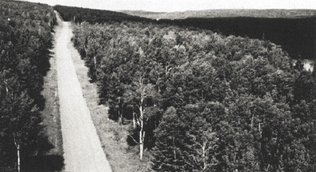
Glossary of terms
- Abutment
- The structure supporting the ends of a bridge and retaining the approach fills. (See sketch)
- Access road
- A road constructed by the public or private sector on Crown land under the authority of the Public Lands Act. These low volume roads generally have a gravel surface.
- Alignment
- The horizontal route or direction of an access road. It is made up of straight line tangent sections and curves.
- Angle of Repose
- The maximum slope or angle at which a material such as soil or loose rock remains stable.
- Apron
- Erosion protection placed below the stream bed in an area of high flow velocity, such as downstream of a culvert.
- Bailey Bridge
- A patented pre-fabricated type of bridge used since 1942 on low volume roads. A variety of bridge lengths and configurations can be assembled from standard components and the unit can be ‘launched’ into position.
- Berm
- A low earth fill constructed in the path of flowing water to divert its direction, or constructed to act as a counter-weight beside the road fill to reduce the risk of foundation failure.
- Camber
- The vertical rise in profile, or hump, such as at the centre of a culvert bedding, which allows for anticipated downward deflection.
- Check Dam
- A low head dam structure constructed in a ditch in the path of flowing water to reduce erosion. Water flows over a check dam, so it is provided with a spill-over section that is erosion-resistant.
- Cofferdam
- A temporary enclosure built in a watercourse and pumped dry to permit work on bridge abutments or piers, thereby separating the work area from the water.
- Corduroy
- Logs placed over a swamp to reinforce the natural root mat for the purpose of minimizing the risk of settlement or foundation failure.
- Crown
- A road is ‘crowned’ when the centre of the road surface is higher than its outer edges to create a cross-gradient of about 4%. This enables water on the surface to drain towards the ditches. (See sketch)
- Culvert, CSP
- Corrugated steel pipe is the common material used for culverts to convey water under an access road. The term refers to the factory-assembled round shapes connected together with couplers.
- Culvert, Multi-plate
- Multi-plate or structural plate culverts are those which, due to their large diameter (usually over 1800 millimetres [six feet]), are normally field-assembled in place. A series of interlocking steel plates are bolted together to make the required shape and length.
- Fish Habitat
- Resources and conditions essential for the production of fish, including water quality and quantity, spawning grounds, nursery, rearing, food supply and migration areas on which fish depend, directly or indirectly, for their life processes.
- Foundation
- The foundation for a bridge may include the underlying soil and the lowest levels of any pier or abutment resting on it. (See sketch)
- Gabion
- A patented woven wire basket filled with stones of minimum size that will not pass through the openings in the basket. Individual baskets are laid in place like building blocks, and then filled to form retaining walls and erosion-resistant surfaces.
- Geo-grid
- A recently-developed product used as a soil reinforcement agent. It is made of polyethylene and is supplied in rolls about two metres (six feet) wide. The product has openings similar to security fencing.
- Geometric Road Standard
- Engineering parameters that define the geometry of a particular road cross-section, alignment and profile grade, are called the geometric road standard. Access roads are generally built to conform with a certain minimum geometric road standard; the higher the standard, the higher the safe travel speed will be.
- Geotextile
- A recently-developed product used as a soil reinforcement agent and as a filter medium. It is made of synthetic fibres manufactured in a woven or loose non-woven manner to form a blanket-like product. It is normally supplied in rolls that would cover four metres wide by 100 metres long (15 by 300 feet).
- Grade or Profile Grade
- The elevation of the top of the finished road is called grade or profile grade. The longitudinal cross-section of a road showing the elevation at various points along the length of a road is called the road profile.
- Gravel, Pit-Run
- The name given to naturally occurring graded material deposited by the retreating glaciers in flowing water (kames, eskers, spill-ways). Gravel is a granular material ranging in size from fine sand to about 50 millimetres (two inches) in diameter.
- Landing
- An area where cut timber is piled before slashing and/or haulage.
- Off-take Ditch
- A ditch excavated to carry roadside drainage away from the roadway to a point downstream and off the right-of-way to which water will flow. In flat terrain an off-take ditch may extend into the bush outside the right-of-way.
- Pier
- On bridges of more than one span, the intermediate supports between abutments are called piers.
- Profile Grade
- See ‘grade’. (See sketch)
- Push-out
- Areas where slash debris, stumps and organic material are deposited in piles off the right-of-way.
- Qf
- The quantity of flow to be used when determining flow velocities during fish migration periods.
- Right-of-way
- The cleared area along the road alignment which contains the roadbed, ditches, road slopes and back slopes. (See sketch)
- Rip Rap
- A layer of boulders or shot rock fragments placed over a soil to protect it from the erosive forces of flowing water. (See sketch)
- Scour
- This is the term used to describe soil erosion when it occurs under water, as in the case of a stream bed or river bottom.
- Shear-blading
- The operation of cutting off trees and brush at ground level by pushing a bulldozer blade along the frozen surface in winter. The stems and trunks are sheared off at ground level.
- Subgrade
- In a vertical cross-section of a road, the subgrade is the surface of the earth cut or earth fill before the placement of selected imported material to construct a sand cushion or gravel surface. (See sketch)
- Swamp
- For the purposes of this document a swamp is a soft deposit of organic or clay material. While the surface may be dry, and even support tree growth, the depth of underlying soft material may be up to 15 metres (50 feet) thick.
- Ten-year Flood
- The maximum quantity of water flow per second expected at a particular water crossing, on average, once every ten years. It has a 10% probability of occurring in any given year. Other return frequencies are defined in a similar manner.
- Use-Management Strategy
- A process used by the Ministry to determine and define the anticipated uses, duration of use, and travel restrictions, for a given access road. Ministry access road planning guidelines require that Use- Management Strategies be developed for all roads on Crown land.
- Water Bars
- Transverse ditches excavated in the surface of an abandoned road to divert surface flow towards the roadside ditches.
- Windrow
- A longitudinal pile of material. For example
a windrow of gravel
is a pile of gravel formed by a grader along the length of the road. - Wingwall
- An extension of a bridge abutment, constructed to retain the roadway fill material and prevent its entry into a water course. (See sketch)
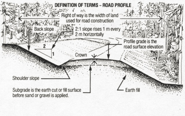
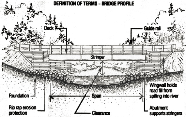
List of references
Ontario government publications:
Guidelines and Criteria for Approval Under the Lakes and Rivers Improvement Act, Ontario Ministry of Natural Resources, 1977.
Highway Construction Practices and Potential Environmental Concerns, Ontario Ministry of Transportation and Communications, 1978.
Class Environmental Assessment for Access Roads to MNR Facilities, Ontario Ministry of Natural Resources, 1984.
Community Fisheries Involvement Program Field Manual, Part One: Trout Stream Rehabilitation, Ontario Ministry of Natural Resources, 1984.
Evaluating Construction Activities Impacting on Water Resources, Part 11 - Guidelines for Construction of Highways and Bridges, Ontario Ministry of the Environment, 1984.
Resource Access Roads, Policy and Implementation Strategies and Guidelines, Ontario Ministry of Natural Resources, 1985.
Turf Establishment Manual, Ontario Ministry of Transportation and Communications, 1986.
Other Canadian publications:
Evaluation of the swimming performance of several fish species from the MacKenzie River, D.R. Jones, J.W., Kiceniuk and O. S. Bamford, Journal Fisheries Research Board of Canada, Volume 31: 1641- 1647, 1974.
Environmental Guidelines for Resource Road Construction, Newfoundland Forest Research Centre, Canadian Forestry Service, Environment Canada, 1978.
Timber Management Guidelines for the Protection of Tourism Values, Ontario Ministry of Natural Resources, 1986.
Class Environmental Assessment for Timber Management on Crown Lands in Ontario, Ontario Ministry of Natural Resources, 1985, revised 1987.
Rehabilitation of Pits and Quarries for Fish and Wildlife, Ontario Ministry of Natural Resources, 1987.
Sand and Gravel Pit Rehabilitation in Northern Ontario, Ontario Ministry of Natural Resources, 1987.
Guidelines on Erosion and Sediment Control for Urban Construction Sites, Ontario Urban Drainage Implementation Committee, 1987.
Timber Management Guidelines for the Protection of Fish Habitat, Ontario Ministry of Natural Resources, 1988.
Timber Management Guidelines for the Provision of Moose Habitat, Ontario Ministry of Natural Resources, 1988.
Drainage Manual, Volumes 1, 2 and 3, Ontario Ministry of Transportation, Current.
Watershed Management Guidelines for Logging and Road Construction in Alberta, R.L. Rothwell, Northern Forest Research Centre, Information Report NOR-X-208, Canadian Forestry Service, Environment Canada, Edmonton, 1978.
A Study of Model and Prototype Culvert Baffling for Fish Passage, C. Katopodis, P.R. Robinson and B.G. Sutherland, Environment Canada Fisheries and Marine Service, Technical Report 828, December 1978.
A Review and Resolution of Fish Passage Problems at Culvert Sites in British Columbia, B.G. Dane, Environment Canada Fisheries and Marine Service Technical Report 810, September 1978.
Liard Highway Hydrology Study, M.M. Dillon Ltd., Canada Department of Indian and Northern Affairs, Ottawa, June 1979.
Bio-engineering for Land Reclamation and Conservation, Hugo Schiechtl, University of Alberta Press, 1980.
Proceedings of Resource Roads Workshops, Whitehorse and Yellowknife, March 16-20, 1981, Canadian Environmental Protection Service, Federal Activities Assessment Branch, Environment Canada, Ottawa, 1981.
A Handbook for Fish Habitat Protection on Forest Lands in British Columbia, Toews and Brownlee, Federal Department of Fisheries and Oceans, Vancouver, 1981.
Forest Access Roads, Planning and Construction Manual, Nova Scotia Department of Lands and Forests, 1982.
Erosion and Sediment Control at Road-Stream Crossings, R.C. Rothwell, The Forestry Chronicle, April 1983.
Handbook of Steel Drainage and Highway Construction Products, Canadian Edition, American Iron and Steel Institute, Washington, 1984.
An Experimental Study of Offset Baffle Culvert Fishways, N. Rajaratnam, S. Lodewyk and C. Katopodis, Technical Report WRE 87-2, Department of Civil Engineering, University of Alberta, 1987.
Nuisance Beaver Control, Saskatchewan Parks and Renewable Resources brochure (undated).
United States publications:
Erosion Control on Highway Construction, Synthesis of Highway Practice, National Cooperative Highway Research Report (NCHRP), Report 18, Transportation Research Board (TRB), Washington, 1973.
Compendium 9, Control of Erosion, Transportation Technology Support for Developing Countries, TRB, Washington, 1979.
Erosion Control During Highway Construction, Manual on Principles and Practices, NCHRP Report 221, TRB, Washington, 1980.
Design of Sedimentation Basins - Synthesis of Highway Practice, NCHRP Report 70, TRB, Washington, 1980.
Construction Cost and Erosion Control Effectiveness of Filter Windrows on Fill Slopes, M. J. Cook and J. G. King, Research Note INT-335, Inter-mountain Forest and Range
Experiment Station, Ogen Utah, U.S. Department of Agriculture, U.S. Forest Service, 1983.
Use of Corrugated Plastic Drainage Tubing for Controlling Water Levels at Nuisance Beaver Sites, K.J. Roblee, New York Fish and Game Journal, Volume 31, Number 1, January 1984.
Erosion and Sediment Control Handbook, Goldman, Jackson and Bursztynsky, McGraw Hill, 1986.
Abilities of Trout to Swim Through Highway Culverts, D.A. Belford, M. Se. Thesis, Montana State University, Bozeman, Montana, July 1986.
5192
(3 k P.R., 88 03 31) ISBN 0-7729-3532-7
ISBN 9-7794-2374-7 (electronic)