O. Reg. 185/22: PORTABLE TRAFFIC CONTROL SYSTEMS, Under: Highway Traffic Act, R.S.O. 1990, c. H.8
Highway Traffic Act
PORTABLE TRAFFIC CONTROL SYSTEMS
Consolidation Period: From April 1, 2022 to the e-Laws currency date.
Last amendment: 185/22.
Legislative History: 185/22.
This is the English version of a bilingual regulation.
CONTENTS
|
Design of signal systems |
|
|
Signal mount |
|
|
Operation and maintenance of signal systems |
|
|
Placement |
|
|
Signs |
|
|
Use of device |
|
|
Design of device |
|
|
Signal mount |
|
|
Gate arm |
|
|
Operation and maintenance of device |
|
|
Placement |
|
|
Signs |
|
Portable Lane Control Signal System
Design of signal systems
1. (1) Every portable lane control signal system shall consist of at least one portable lane control signal for each direction from which traffic to be controlled by the system approaches.
(2) A portable lane control signal shall have a set of lenses that meets the following criteria:
1. The set must contain no lens other than one red lens, one amber lens and one green lens.
2. The lenses in the set must be arranged vertically in the following order, commencing at the bottom: green, amber and red.
3. Each lens in the set must be at least 20 centimetres in diameter.
Signal mount
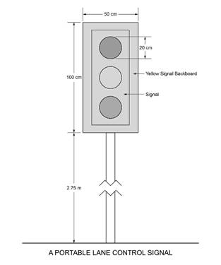
2. (1) A portable lane control signal shall be mounted on a yellow backboard that,
(a) is not less than 100 centimetres in height and not less than 50 centimetres in width; and
(b) is placed so that the bottom edge of the backboard is at least 2.75 metres above the level of the roadway.
(2) If a backboard has dimensions greater than 100 centimetres in height and 50 centimetres in width, the increased dimensions must be proportional relative to each other.
(3) Figure 1 is an illustration of a portable lane control signal that meets the requirements set out in this section and section 1.
Text alternative: Illustration of portable lane control signal. Bottom of signal backboard is 2.75 m above the roadway. The yellow backboard for the portable lane control signal is rectangular in shape measuring 100 cm high and 50 cm wide. Each of the three circular lenses is 20 cm in diameter. This text alternative is provided for convenience only and does not form part of the official law.
Operation and maintenance of signal systems
3. (1) A portable lane control signal system shall not be operated in such a manner as to show green and amber lenses illuminated simultaneously.
(2) Each lamp and each lens in a portable lane control signal shall be maintained so that, when the lamp is illuminated, the lens is clearly visible to approaching traffic at a distance of at least 100 metres.
Placement
4. (1) A portable lane control signal system shall be placed on a highway such that one portable lane control signal is to the right of, facing and clearly visible to approaching traffic.
(2) A portable lane control signal system shall not be located at an intersection or pedestrian crossover.
(3) A portable lane control signal system shall not be located in any place or manner so as to conflict with any traffic control signal system.
Signs
5. Signs shall be erected in accordance with the following rules:
1. The following signs shall be erected in front of each portable lane control signal in a portable lane control signal system:
i. A DO NOT PASS sign, as prescribed in Regulation 615 of the Revised Regulations of Ontario, 1990 made under the Act.
ii. A sign with an orange background indicating that a portable lane control signal is ahead.
iii. A sign indicating the location at which a driver approaching a portable lane control signal system is to bring their vehicle to a stop.
2. The signs shall be erected in the order set out in paragraph 1 commencing farthest from the portable lane control signal.
3. The signs shall be located to the right of, facing and clearly visible to approaching traffic.
4. The signs shall bear the markings as illustrated in Figure 2 unless the signs are erected in an area designated by the French Language Services Act, in which case the signs shall bear the markings as illustrated in Figure 3.
5. Despite paragraph 4, if a municipality that is in a designated area has not passed a by-law under subsection 14 (1) of the French Language Services Act, the signs erected in that area shall bear the markings illustrated in either Figure 2 or Figure 3.
6. Each sign shall be ground-mounted or mounted on a portable stand.
7. If a sign is ground-mounted, the bottom edge of the sign shall be at least 1.5 metres but not more than 2.5 metres above the level of the roadway.
8. If a sign is mounted on a portable stand, the bottom edge of the sign shall be at least 1.0 metres but not more than 2.5 metres above the level of the roadway.
9. Each sign shall have a retro-reflective background.
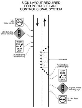
Text alternative: Figure of the placement of a portable lane control signal system placed on the right side facing each direction of traffic on a highway along with three signs erected in front of the portable lane control signal and facing traffic. The outermost sign is a “DO NOT PASS” sign, followed by a “SIGNALS AHEAD” warning sign and finally a “STOP HERE ON RED SIGNAL” sign that has a thick black arrow pointed diagonally and downward. The last sign is placed the closest to the portable lane control signal system in front of the coned off work area which is blocking half of the roadway in the Figure. This text alternative is provided for convenience only and does not form part of the official law.
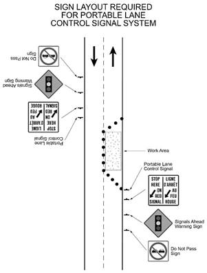
Text alternative: Figure of the placement of a portable lane control signal system placed on the right side facing each direction of traffic on a highway along with three signs erected in front of the portable lane control signal and facing traffic. The outermost sign is a “DO NOT PASS” sign, followed by a “SIGNALS AHEAD” warning sign and finally a “STOP HERE ON RED SIGNAL / LIGNE D’ARRÊT AU FEU ROUGE” sign that has a thick black arrow pointed diagonally and downward. The last sign is placed the closest to the portable lane control signal system in front of the coned off work area which is blocking half of the roadway in the Figure. This text alternative is provided for convenience only and does not form part of the official law.
Automated Flagger Assistance Devices
Use of device
6. An automated flagger assistance device shall be operated in accordance with this Regulation.
Design of device
7. (1) Every automated flagger assistance device shall consist of a gate arm and a signal.
(2) The signal on an automated flagger assistance device shall have a set of lenses that meets the following criteria:
1. The set must contain no lens other than one red lens and one amber lens.
2. The lenses in the set must be arranged vertically in the following order, commencing at the bottom: amber and red.
3. Each lens in the set must be at least 30 centimetres in diameter.
Signal mount
8. The signal on an automated flagger assistance device shall be mounted on a black backboard that,
(a) is not less than 85 centimetres in height and not less than 50 centimetres in width;
(b) has an orange retro-reflective border that is at least 2.5 centimetres in width; and
(c) is placed so that the bottom edge of the backboard is at least two metres above the level of the roadway.
Gate arm
9. (1) The gate arm of an automated flagger assistance device shall meet the following criteria:
1. The gate arm must be at least two metres long and at least 10 centimetres wide.
2. The gate arm must be covered on both sides with alternating vertical contrasting stripes. At least one set of stripes must be made of retro-reflective sheeting.
Note: On July 1, 2027, paragraph 2 of subsection 9 (1) of the Regulation is revoked and the following substituted: (See: O. Reg. 185/22, s. 13)
2. The gate arm must be covered on both sides with alternating vertical stripes of orange and black. The orange stripes must be made of retro-reflective sheeting.
3. When lowered, the bottom edge of the gate arm must be not less than 110 centimetres but not more than 140 centimetres above the level of the roadway.
(2) Figure 4 is an illustration of an automated flagger assistance device that meets the requirements set out in this section and sections 7 and 8.
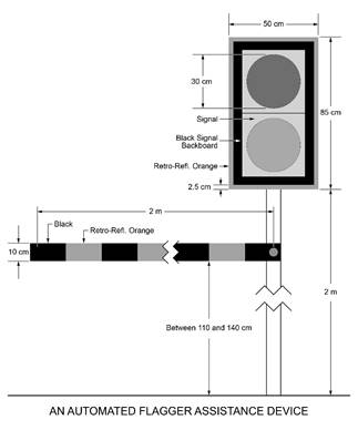
Text Alternative: Illustration showing an automated flagger assistance device comprising a signal and a gate arm. The signal has a circular red lens stacked vertically above a circular amber lens. The signal has a rectangular black backboard with a 2.5 cm orange, retro-reflective border. The bottom of the backboard is two metres above the roadway. The backboard is 85 cm high and 50 cm wide. Each of the circular lenses is 30 cm in diameter. The gate arm is two metres long and 10 cm wide with alternating vertical black and retro-reflective orange stripes and, when lowered, is between 110 cm and 140 cm above the roadway. This text alternative is provided for convenience only and does not form part of the official law.
Operation and maintenance of device
10. (1) The gate arm of an automated flagger assistance device shall be horizontal when a red lens is illuminated.
(2) The gate arm of an automated flagger assistance device shall be raised when an amber lens is illuminated.
(3) An automated flagger assistance device shall not be operated in such a manner as to show amber and red lenses illuminated simultaneously to approaching traffic.
(4) To indicate to approaching traffic that the signal is about to change from amber to red, the lenses in the signal of an automated flagger assistance device shall be illuminated in the following sequence:
1. Flashing amber.
2. Solid amber.
3. Solid red.
(5) Each lamp and each lens in the signal of an automated flagger assistance device shall be maintained so that, when the lamp is illuminated, the lens is clearly visible to approaching traffic at a distance of at least 165 metres.
(6) An automated flagger assistance device shall not be operated unless a traffic control person is positioned close enough to the device to enable the person to immediately display a traffic control stop or slow sign to approaching traffic if the device malfunctions.
Placement
11. (1) An automated flagger assistance device shall be placed on a highway such that the signal of the device is to the right of, facing and clearly visible to approaching traffic.
(2) An automated flagger assistance device shall not be located at an intersection or pedestrian crossover.
(3) An automated flagger assistance device shall not be located in any place or manner so as to conflict with any traffic control signal system.
Signs
12. Signs shall be erected in accordance with the following rules:
1. The following signs shall be erected in front of each automated flagger assistance device:
i. A DO NOT PASS sign, as prescribed in Regulation 615 of the Revised Regulations of Ontario, 1990 made under the Act.
ii. A sign with an orange background indicating that an automated flagger assistance device is ahead.
iii. A sign indicating the location at which a driver approaching an automated flagger assistance device is to bring their vehicle to a stop.
2. The signs shall be erected in the order set out in paragraph 1 commencing farthest from the automated flagger assistance device.
3. The signs shall be located to the right of, facing and clearly visible to approaching traffic.
4. The signs shall bear the markings as illustrated in Figure 5 unless the signs are erected in an area designated by the French Language Services Act, in which case the signs shall bear the markings as illustrated in Figure 6.
5. Despite paragraph 4, if a municipality that is in a designated area has not passed a by-law under subsection 14 (1) of the French Language Services Act, the signs erected in that area shall bear the markings illustrated in either Figure 5 or Figure 6.
6. Each sign shall be ground-mounted or mounted on a portable stand.
7. If a sign is ground-mounted, the bottom edge of the sign shall be at least 1.5 metres but not more than 2.5 metres above the level of the roadway.
8. If a sign is mounted on a portable stand, the bottom edge of the sign shall be at least 1.0 metres but not more than 2.5 metres above the level of the roadway.
9. Each sign shall have a retro-reflective background.
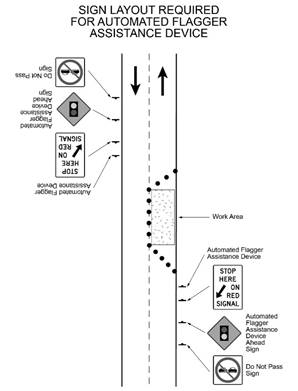
Text Alternative: Illustration showing the placement of automated flagger assistance devices placed on the right side of a two-lane highway facing each direction of traffic along with three signs erected in front of each automated flagger assistance device and facing traffic. The outermost sign is a “DO NOT PASS” sign, followed by an “Automated Flagger Assistance Device Ahead” warning sign and, finally, a “STOP HERE ON RED SIGNAL” sign that has a thick black arrow pointed diagonally and downward. The last sign is placed closest to the automated flagger assistance device in front of the work area which is blocking half of the roadway in the illustration. This text alternative is provided for convenience only and does not form part of the official law.
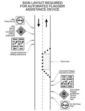
Text Alternative: Illustration of the placement of automated flagger assistance devices placed on the right side of a two-lane highway facing each direction of traffic along with three signs erected in front of each automated flagger assistance device and facing traffic. The outermost sign is a “DO NOT PASS” sign, followed by an “Automated Flagger Assistance Device Ahead” warning sign and, finally, a “STOP HERE ON RED SIGNAL / LIGNE D’ARRÊT AU FEU ROUGE” sign that has a thick black arrow pointed diagonally and downward. The last sign is placed closest to the automated flagger assistance device in front of the work area which is blocking half of the roadway in the illustration. This text alternative is provided for convenience only and does not form part of the official law.
13. Omitted (provides for amendments to this Regulation).
14. Omitted (revokes other legislation).
15. Omitted (provides for coming into force of provisions of this Regulation).