R.R.O. 1990, Reg. 768: SURVEYS OF MINING CLAIMS, Mining Act, R.S.O. 1990, c. M.14
Mining Act
Loi sur les mines
R.R.O. 1990, REGULATION 768
SURVEYS OF MINING CLAIMS
Historical version for the period August 16, 2017 to November 27, 2017.
Last amendment: O. Reg. 331/17.
This Regulation is made in English only.
1. Immediately after the completion of every survey of a mining claim, the surveyor shall deliver or forward by registered mail to the Surveyor General, by his or her official title, the surveyor’s returns of survey as specified by section 3. R.R.O. 1990, Reg. 768, s. 1.
2. All surveys of mining claims are subject to inspection and, in the event of the work not being found correct and in compliance with this Regulation, the surveyor shall make such amendments as are ordered by the Surveyor General. R.R.O. 1990, Reg. 768, s. 2.
3. The following returns of survey of a mining claim shall be forwarded to the Surveyor General:
1. One certified copy of the field notes on durable tracing linen.
2. One certified copy of the plan of each individual claim on durable tracing linen.
3. One certified copy of the application to record and sketch.
4. A tabulated list, certified correct, of the prospector’s posts bearing legible markings at the time of survey, and of all survey posts and, in the absence of survey posts, a brief description of the manner in which the survey corner was re-established.
5. A tabulated list of latitudes and departures.
6. A metes and bounds description of each mining claim situated in a subdivided township.
7. Where a mining claim is situated in a township lot of a subdivided township or recorded as an aliquot part of a mining location, paragraph 4 does not apply. R.R.O. 1990, Reg. 768, s. 3.
4. The following returns of survey of a mining claim shall be forwarded to the mining recorder:
1. One white or blue print of the field notes.
2. Two copies of the plan of each individual claim on durable tracing linen.
3. A metes and bounds description of each mining claim situated in a subdivided township. R.R.O. 1990, Reg. 768, s. 4.
5. The scale of the plan and field notes shall vary between five to ten chains to an inch, depending on the size of the claims and the detail to be shown. R.R.O. 1990, Reg. 768, s. 5.
6. Where a group of claims is surveyed, the field notes may be shown on one compiled plan, if the plan does not exceed an area of five square feet. R.R.O. 1990, Reg. 768, s. 6.
7. Measurements shall be shown in chains and decimals of a chain. R.R.O. 1990, Reg. 768, s. 7.
8. The direction of the surveyed lines shall be shown by astronomical bearings, referred to the reference meridian passing through the centre of the township but, where a mining claim is not situated in a township, the bearings shall be referred to a reference meridian through the point of observation. R.R.O. 1990, Reg. 768, s. 8.
9. (1) In every group, or connected group of mining claims, six or more in number, whether surveyed at one time, or at different times by the same surveyor, an astronomical observation for azimuth shall be taken and, where the group exceeds twelve in number, a check observation for azimuth shall be made for each multiple of twelve claims.
(2) Where the group is less than six in number, the bearings may be referred to a previously surveyed line, claim or parcel of record in the Ministry, if the bearings shown are reliable. R.R.O. 1990, Reg. 768, s. 9.
10. The surveyor shall mark out the boundaries of the mining claim by blazing the adjacent trees on three sides, one blaze on the face of the tree on the direction of the line and one blaze on each face of the tree at right angles to the direction of the line, the lines being well cut out and straight between survey posts. R.R.O. 1990, Reg. 768, s. 10.
11. (1) The surveyor shall plant at each angle of the claim a metal post not less than five-eighths of an inch square or three-quarters of an inch in diameter and not less than eighteen inches in length, with the number of the post permanently marked thereon together with the recorded number and letter or letters of the claim and shall also plant at each metal post a durable wooden post, not less than four inches square and thirty-six inches in length, marked in the same manner as the metal post.
(2) Where, owing to physical features, it is not practicable to plant a post at the true corner of the claim, a witness post shall be planted in lieu thereof and marked “W.P.” together with the number of the post, recorded number of the claim and letters pertaining thereto. R.R.O. 1990, Reg. 768, s. 11.
12. The marks on the survey posts and bearing trees shall be made in a neat and workmanlike manner with a sharp knife or scribing iron. R.R.O. 1990, Reg. 768, s. 12.
13. Where available, each survey corner shall be referenced by two bearing trees, preferably at right angles to the survey post, and the measurements shall be made from the blaze to the survey post. R.R.O. 1990, Reg. 768, s. 13.
14. The survey of a mining claim shall be connected with a previously surveyed claim, parcel, line or traverse post of record in the Ministry if the survey is within a radius of two miles, and in other cases, the surveyor shall select a prominent point at which to plant a permanent post. R.R.O. 1990, Reg. 768, s. 14.
15. Where a mining claim is composed partly of land and partly of land under water, the normal or average high-water mark shall constitute the boundary. R.R.O. 1990, Reg. 768, s. 15.
Data to be Shown on Field Notes
16. (1) Survey posts, bearing trees, observations, scale, north point, adjacent claims surveyed or unsurveyed, streams, roads, power or telephone lines, surveyed lines and the connections made thereto and the high-water mark shall be shown on field notes, and traverses shall be made of all lakes and rivers situated within the limit of the mining claim, and all traverse lines shall be shown in a good quality of vermilion ink and the measurements and bearings of the traverse and boundary lines shall be shown in black india ink. R.R.O. 1990, Reg. 768, s. 16 (1).
(2) The title of the field notes shall mention each claim number surveyed and the township or area, together with the district in which the claim is situated. R.R.O. 1990, Reg. 768, s. 16 (2).
(3) The surveyor who completes the survey of a mining claim shall include on his or her field notes a certificate in which the surveyor certifies that he or she,
(a) has carefully examined the ground included in the mining claim;
(b) has made all reasonable investigations in his or her power to ascertain if there is a subsisting claim that conflicts with the mining claim; and
(c) has found no track or indication and has no knowledge or information of subsisting claims that conflict with the mining claim except for those subsisting claims, if any, listed in the certificate. O. Reg. 331/17, s. 1.
(4) A certificate under subsection (3) shall,
(a) identify the mining claim number of the mining claim and any subsisting claims that conflict with the mining claim; and
(b) be signed by the surveyor, indicating below the signature line the surveyor’s title as an Ontario land surveyor. O. Reg. 331/17, s. 1.
17. (1) The title on the plan shall mention the claim number, the township or area, together with the district in which the claim is situated and, where a mining claim is composed of a part of a township lot or recorded as being an aliquot part of a mining location, the title shall first mention the township lot or mining location and then the recorded mining claim number. R.R.O. 1990, Reg. 768, s. 17 (1).
(2) The measurements, bearings and boundary lines shall be shown in black india ink and the boundary lines shall be outlined in a light red colour. R.R.O. 1990, Reg. 768, s. 17 (2).
(3) All streams, roads, power or telephone lines, surveyed lines and the connections thereto shall be shown, and a water line shall be shown around the shores of all lakes and rivers but the traverse thereof need not be shown. R.R.O. 1990, Reg. 768, s. 17 (3).
(4) The adjacent mining claims shall be shown and if the adjacent claim is not surveyed, the words “not surveyed” shall also be shown. R.R.O. 1990, Reg. 768, s. 17 (4).
(5) Revoked: O. Reg. 331/17, s. 2.
18. The area of a mining claim shall be computed to two places of decimals and, where a claim is composed partly of land and partly of land under water, or partly in two townships, separate areas shall be computed. R.R.O. 1990, Reg. 768, s. 18.
19. The closing error of a surveyed mining claim shall not exceed a ratio of 1 in 2,000, or the square root of the sum of the squares of the closing error in latitude and departure shall not exceed four links in a standard size claim of twenty chains square. R.R.O. 1990, Reg. 768, s. 19.
Duty of Surveyor Before Commencing Survey
20. (1) Except as herein provided, no survey shall be made within a distance of fifteen miles in a straight line from the recorder’s office without the written consent or direction of the recorder or of the Commissioner, or of the Minister or Deputy Minister, and, before proceeding with the survey, the surveyor shall examine the application and sketch or plan of the claim or certified copies thereof.
(2) Where a claim is fifteen miles or more in a straight line from the recorder’s office, and where the surveyor has not applied for the consent or direction under subsection (1), the surveyor may survey the claim but, before signing the certificate required by section 16, the surveyor shall in all other respects follow the procedure under subsection (1) and shall, in addition to the survey, file with the recorder a sworn statement setting out the circumstances under which the survey was made without the consent referred to in subsection (1). R.R.O. 1990, Reg. 768, s. 20.
21. (1) In surveying a mining claim in unsurveyed territory, the surveyor shall establish the boundaries of the claim by running straight lines from the No. 1 post at the northeast angle of the claim to the No. 2 post at the southeast angle thereof, from the No. 2 post to No. 3 post at the southwest angle thereof and from No. 3 post to No. 4 post at the northwest angle thereof, and from No. 4 post to No. 1 post and, where two mining claims are shown as having a common boundary in whole or in part, the boundary of the prior subsisting claim governs.
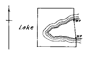
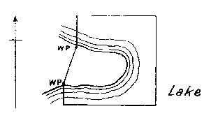
(2) In establishing the boundaries of a mining claim in unsurveyed territory where, owing to the nature and conformation of the ground, the true angle or angles of the claim could not be posted, and the position thereof is indicated by witness posts as illustrated in each of the diagrams hereto, the surveyor shall follow the method described in the note to the diagram, having due regard to prior subsisting claims and to subsection 97 (2) of the Act.
(3) The posts as shown by the diagrams hereto are located on the ground by survey. R.R.O. 1990, Reg. 768, s. 21.
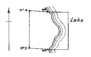
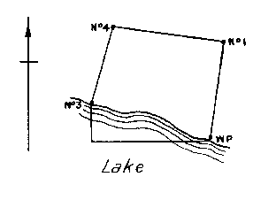
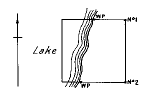
Diagram No. 1
Insert regs\graphics\1990\768\768fg01u.tif
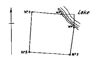
Note
Draw a line north astronomically from the witness post on the east boundary to intersect a line drawn east astronomically from the witness post on the north boundary.
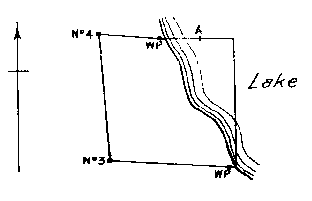
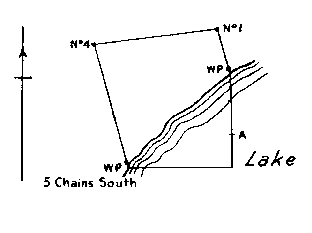
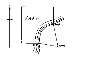
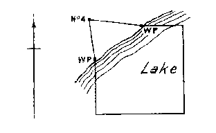
Diagram No. 2
Insert regs\graphics\1990\768\768fg02u.tif
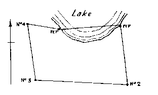
Note
Explanation: The Prospector’s Sketch Indicates The Position Of The Witness Posts As Shown By Diagram No. 1.
Procedure: Accept witness post on the east boundary as the No. 1 post and join in a straight line to the witness post on the north boundary.
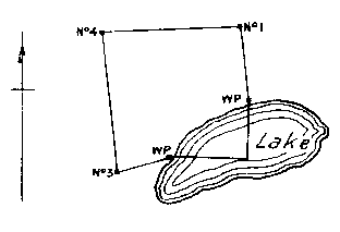
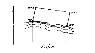
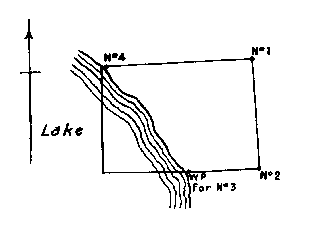
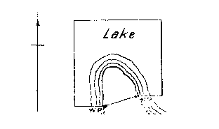
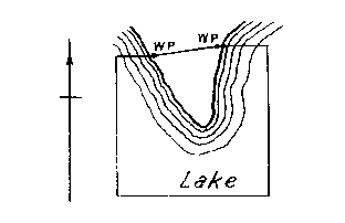
Diagram No. 3
Insert regs\graphics\1990\768\768fg03u.tif
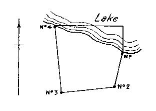
Note
Draw a line north astronomically from the witness post on the east boundary to intersect a line drawn east astronomically from the No. 4 post.
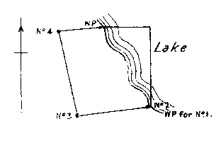
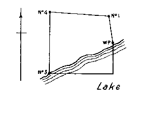
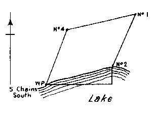
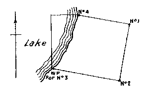
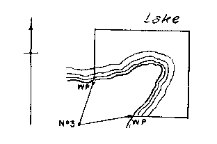
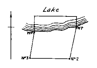
Diagram No. 4
Insert regs\graphics\1990\768\768fg04u.tif

Note
Explanation: The prospector’s sketch indicates the position of the witness posts as shown by Diagram No. 3.
Procedure: Accept the witness post on the east boundary as the No. 1 post and draw a line west astronomically from this point to intersect a line drawn north astronomically from the prospector’s No. 4 post.
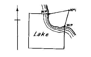
Insert regs\graphics\1990\768\768fg05u.tif
Note
Draw a line north astronomically from the No. 2 post to intersect a line drawn east astronomically from the witness post on the north boundary.
Diagram No. 6
Insert regs\graphics\1990\768\768fg06u.tif
Note
Draw a line east astronomically from the witness post on the north boundary the “call” distance; thence from this point draw a line south astronomically to intersect a line drawn east astronomically from the witness post on the south boundary.
Diagram No. 7
Insert regs\graphics\1990\768\768fg07u.tif
Note
The “call” distance from the witness post on the north boundary extends only to point “A” and a line projected south astronomically from “A” intersects the south boundary west of the witness post.
Procedure: Accept witness post on the south boundary as the No. 2 post and proceed as in Diagram 5.
Diagram No. 8
Insert regs\graphics\1990\768\768fg08u.tif
Note
Draw a line south astronomically from the witness post on the east boundary to intersect a line drawn east astronomically from the witness post on the south boundary.
Diagram No. 9
Insert regs\graphics\1990\768\768fg09u.tif
Note
Draw a line south astronomically from the witness post on the east boundary to intersect a line drawn east astronomically from the No. 3 post.
Diagram No. 10
Insert regs\graphics\1990\768\768fg10u.tif
Note
Explanation: The prospector’s sketch indicates the position of the No. 3 and witness posts as shown by Diagram No. 9.
Procedure: Accept the witness post on the east boundary as the No. 2 post and from this point draw a line west astronomically to intersect a line drawn south astronomically from the prospector’s No. 3 post.
Diagram No. 11
Insert regs\graphics\1990\768\768fg11u.tif
Note
The “call” distance from the witness post on the east boundary extends only to point “A”. A line projected west astronomically from point “A” intersects the west boundary north of the witness post.
Procedure: Accept the witness post on the west boundary as the No. 3 post and draw a line east astronomically from this point to intersect a line drawn south astronomically from the witness post on the east boundary.
Diagram No. 12
Insert regs\graphics\1990\768\768fg12u.tif
Note
Draw a line south astronomically from the witness post on the east boundary the “call” distance, and from this point draw a line west astronomically to intersect a line drawn south astronomically from the witness post on the west boundary.
Diagram No. 13
Insert regs\graphics\1990\768\768fg13u.tif
Note
Explanation: The prospector’s sketch indicates that the witness post is north of the No. 2 post.
Accept witness post on the west boundary as the No. 3 post and from this point draw a line east astronomically to intersect a line drawn south astronomically from the prospector’s No. 2 post.
Diagram No. 14
Insert regs\graphics\1990\768\768fg14u.tif
Note
Draw a line west astronomically from the witness post on the south boundary the “call” distance, and from this point draw a line north astronomically to intersect a line drawn west astronomically from the witness post on the north boundary.
Diagram No. 15
Insert regs\graphics\1990\768\768fg15u.tif
Note
Draw a line west astronomically from the witness post on the south boundary to intersect a line drawn south astronomically from the No. 4 post.
Diagram No. 16
Insert regs\graphics\1990\768\768fg16u.tif
Note
Explanation: The prospector’s sketch indicates the position of the No. 4 post and witness post as shown by Diagram No. 15.
Procedure: Accept witness post on the south boundary as the No. 3 post and from this point draw a line north astronomically to intersect a line drawn west astronomically from the prospector’s No. 4 post.
Diagram No. 17
Insert regs\graphics\1990\768\768fg17u.tif

Note
The “call” distance from the witness post on the south boundary extends only to point “A”. A line projected north astronomically from point “A” intersects the north boundary east of the witness post.
Procedure: Accept witness post on the north boundary as the No. 4 post and draw a line south astronomically from this point to intersect a line drawn west astronomically from the witness post on the south boundary.
Diagram No. 18
Insert regs\graphics\1990\768\768fg18u.tif
Note
Draw a line south astronomically from the post on the easterly boundary the “call” distance; thence west astronomically 20 chains; thence north astronomically to intersect a line drawn west astronomically from the witness post on the northerly boundary.
Diagram No. 19
Insert regs\graphics\1990\768\768fg19u.tif
Note
Draw a line north astronomically from the northerly witness post the “call” distance to establish the northeasterly angle of the claim. From the southerly witness post draw a line south astronomically the “call” distance to establish the southeasterly angle; thence west astronomically 20 chains; thence north astronomically to intersect a line drawn west astronomically from the northeasterly angle.
Diagram No. 20
Insert regs\graphics\1990\768\768fg20u.tif
Note
Draw a line north astronomically the “call” distance to establish the northeasterly angle. From the witness post on the southerly boundary draw a line west astronomically the “call” distance to establish the southwesterly angle; thence north astronomically to intersect a line drawn west astronomically from the northeasterly angle.
Diagram No. 21
Insert regs\graphics\1990\768\768fg21u.tif
Note
Draw a line east astronomically from the easterly witness post the “call” distance; thence north astronomically 20 chains to establish the northeasterly angle. From the westerly witness post draw a line west astronomically the “call” distance; thence north astronomically to intersect a line drawn west astronomically from the northeasterly angle.
Diagram No. 22
Insert regs\graphics\1990\768\768fg22u.tif
Note
From the witness post on the southerly limit, draw a line east astronomically the “call” distance; thence north astronomically 20 chains to establish the northeasterly angle. From the witness post on the westerly limit draw a line north astronomically to intersect a line drawn west astronomically from the northeasterly angle.
Diagram No. 23
Insert regs\graphics\1990\768\768fg23u.tif
Note
From the northerly witness post on the westerly limit draw a line north astronomically the “call” distance; thence east astronomically 20 chains to establish the northeasterly angle; thence south astronomically 20 chains. From the southerly witness post draw a line south astronomically to intersect a line drawn west astronomically from the southeasterly angle.
Diagram No. 24
Insert regs\graphics\1990\768\768fg24u.tif
Note
From the witness post on the northerly limit draw a line east astronomically the “call” distance to establish the northeasterly angle; thence south astronomically 20 chains; thence west astronomically to intersect a line drawn south astronomically from the witness post on the westerly limit.
Diagram No. 25
Insert regs\graphics\1990\768\768fg25u.tif
Note
From the easterly witness post draw a line east astronomically the “call” distance to establish the northeasterly angle; thence south astronomically 20 chains; thence west astronomically 20 chains; thence north astronomically to intersect a line drawn west astronomically from the westerly witness post.
Diagram No. 26
Insert regs\graphics\1990\768\768fg26u.tif
Note
From the witness post on the easterly boundary draw a line north astronomically the “call” distance to establish the northeasterly angle. From the witness post on the westerly boundary draw a line north astronomically to intersect a line drawn west astronomically from the westerly witness post.
Diagram No. 27
Insert regs\graphics\1990\768\768fg27u.tif
Note
Explanation: Prospector’s sketch indicates the position of the witness posts, as shown in Diagram No. 26.
The “call” distance from the witness post on the east boundary extends only to point “A”. A line projected west astronomically from point “A” intersects the west boundary south of the witness post.
Procedure: Accept the witness post on the west boundary as the No. 4 post and draw a line east astronomically from the point to intersect a line drawn north astronomically from the witness post on the east boundary.
Diagram No. 28
Insert regs\graphics\1990\768\768fg28u.tif
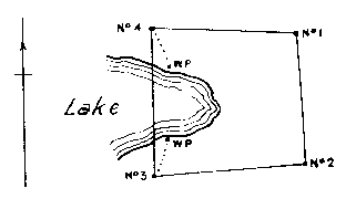
Note
Witness posts were planted by the prospector on each side of a small lake on the west boundary, but all corners of the claim were duly marked with posts. Establish west boundary by a straight line between the No. 3 and 4 posts, disregarding the witness posts.
Diagram No. 29
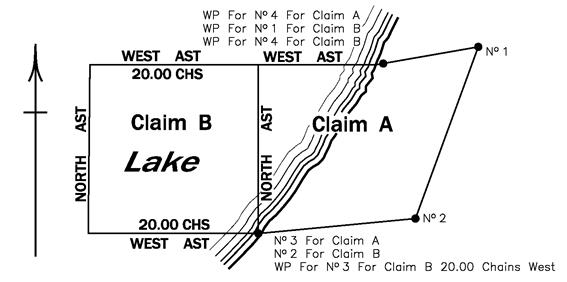
Note
Establish boundaries of Claim “A” as indicated by diagram.
Diagram No. 30
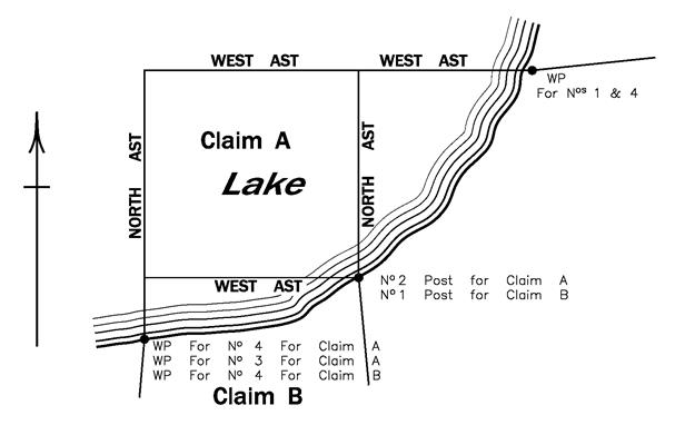
Note
Establish boundaries of Claims “A” and “B” as indicated by diagram.
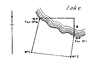
Diagram No. 31
Insert regs\graphics\1990\768\768fg31u.tif
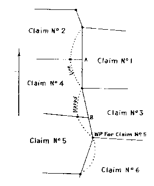
(Illustrating proviso in subsection 21 (1) )
Note
The claims were staked as partly shown by this diagram in order of priority, as shown by the numbers. Part of the westerly boundaries of Claim No. 1 and Claim No. 3 will form the easterly boundary of Claim No. 4 and, in the survey of No. 4, the surveyor will plant the corner posts at points “A” and “B” but show on his or her field notes the position of the prospector’s posts. Establish the east boundary of Claim No. 5 as shown by diagram and not by a straight line between point “B” and the No. 2 post.
Diagram No. 32
Insert regs\graphics\1990\768\768fg32u.tif
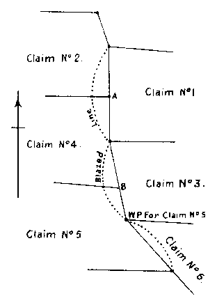
(Illustrating proviso in subsection 21 (1) )
Note
Establish that part of the east boundary of Claim No. 5 lying south of the No. 3 post of Claim No. 3 by a straight line between the No. 3 post of Claim No. 3 and the No. 2 post of Claim No. 5 and not by a straight line between point “B” and the No. 2 post.
R.R.O. 1990, Reg. 768, Diagrams 1-32.