O. Reg. 332/12: BUILDING CODE, Building Code Act, 1992, S.O. 1992, c. 23
Building Code Act, 1992
Loi de 1992 sur le code du bâtiment
BUILDING CODE
Note: This Regulation was revoked on January 1, 2025. (See: O. Reg. 163/24, s. 3)
Last amendment: 163/24.
Legislative History: 151/13, 360/13, 361/13, 368/13, 191/14, 139/17, 462/17, 563/17, 79/18, 388/18, 87/19, 88/19, 209/20, 511/20, 762/20, 867/21, 217/22, 434/22 (as am. by 31/23 and 156/24), 451/22, 30/23, 89/23, 390/23, 73/24, 155/24, 158/24, 163/24.
This Regulation is made in English only.
DIVISION A
COMPLIANCE, OBJECTIVES AND FUNCTIONAL STATEMENTs
Part 1
Compliance and General
| Section | 1.1. | Organization and Application |
|
| 1.1.1. | Organization of this Code |
|
| 1.1.2. | Application of Division B |
|
| 1.1.3. | Building Size Determination |
|
|
|
|
| Section | 1.2. | Compliance |
|
| 1.2.1. | Compliance with Division B |
|
| 1.2.2. | Materials, Appliances, Systems and Equipment |
|
|
|
|
| Section | 1.3. | Interpretation |
|
| 1.3.1. | Interpretation |
|
|
|
|
| Section | 1.4. | Terms and Abbreviations |
|
| 1.4.1. | Definitions of Words and Phrases |
|
| 1.4.2. | Symbols and Other Abbreviations |
|
|
|
|
| Section | 1.5. | Referenced Documents and Organizations |
|
| 1.5.1. | Referenced Documents |
|
| 1.5.2. | Organizations |
Section 1.1. Organization and Application
1.1.1. Organization of this Code
1.1.1.1. Scope of Division A
(1) Division A contains compliance and application provisions and the objectives and functional statements of this Code.
1.1.1.2. Scope of Division B
(1) Division B contains the acceptable solutions of this Code.
1.1.1.3. Scope of Division C
(1) Division C contains the administrative provisions of this Code.
1.1.1.4. Internal Cross-references
(1) If a provision of this Code contains a reference to another provision of this Code but no Division is specified, both provisions are in the same Division of this Code.
1.1.2. Application of Division B
1.1.2.1. Application of Parts 1, 7 and 12
(1) Part 1 of Division B applies to all buildings.
(2) Subject to Article 1.1.2.6., Parts 7 and 12 of Division B apply to all buildings.
1.1.2.2. Application of Parts 3, 4, 5 and 6
(1) Subject to Articles 1.1.2.6. and 1.3.1.2., Parts 3, 5 and 6 of Division B apply to all buildings,
(a) used for major occupancies classified as,
(i) Group A, assembly occupancies,
(ii) Group B, care, care and treatment or detention occupancies, or
(iii) Group F, Division 1, high hazard industrial occupancies,
(b) exceeding 600 m2 in building area or exceeding three storeys in building height and used for major occupancies classified as,
(i) Group C, residential occupancies,
(ii) Group D, business and personal services occupancies,
(iii) Group E, mercantile occupancies,
(iv) Group F, Divisions 2 and 3, medium hazard industrial occupancies and low hazard industrial occupancies, or
(c) used for retirement homes.
(2) Subject to Articles 1.1.2.6. and 1.3.1.2., Part 4 of Division B applies to,
(a) post-disaster buildings,
(b) buildings described in Sentence (1),
(c) a retaining wall exceeding 1 000 mm in exposed height adjacent to,
(i) public property,
(ii) access to a building, or
(iii) private property to which the public is admitted,
(d) a pedestrian bridge appurtenant to a building,
(e) a crane runway,
(f) an exterior storage tank and its supporting structure that is not regulated by the Technical Standards and Safety Act, 2000,
(g) signs regulated by Section 3.15. of Division B that are not structurally supported by a building,
(h) a structure that supports a wind turbine generator having a rated output of more than 3 kW,
(i) an outdoor pool that has a water depth greater than 3.5 m at any point, and
(j) a permanent solid nutrient storage facility with supporting walls exceeding 1 000 mm in exposed height.
(3) Section 3.11. of Division B applies to public pools.
(4) Section 3.12. of Division B applies to public spas.
(5) Section 3.15. of Division B applies to signs.
(6) Section 3.16A. of Division B applies to demountable stages and demountable support structures.
1.1.2.3. Application of Part 8
(1) Subject to Article 1.1.2.6., Part 8 of Division B applies to the design, construction, operation and maintenance of all sewage systems and to the construction of buildings in the vicinity of sewage systems.
1.1.2.4. Application of Part 9
(1) Subject to Article 1.1.2.6 Part 9 of Division B applies to all buildings,
(a) of three or fewer storeys in building height,
(b) having a building area not exceeding 600 m2, and
(c) used for major occupancies classified as,
(i) Group C, residential occupancies other than buildings used for retirement homes,
(ii) Group D, business and personal services occupancies,
(iii) Group E, mercantile occupancies, or
(iv) Group F, Divisions 2 and 3, medium hazard industrial occupancies and low hazard industrial occupancies.
1.1.2.5. Application of Part 10
(1) Part 10 of Division B applies to existing buildings requiring a permit under section 10 of the Act.
1.1.2.6. Application of Part 11
(1) Except as provided in Sentence (2), Part 11 of Division B applies to the design and construction of existing buildings, or parts of existing buildings, that have been in existence for at least five years.
(2) If a building has been in existence for at least five years but includes an addition that has been in existence for less than five years, Part 11 of Division B applies to the entire building.
1.1.2.7. Existing Buildings
(1) Except as provided in Section 3.17. of Division B, Section 9.40. of Division B and Part 11 of Division B, if an existing building is extended or is subject to material alteration or repair, this Code applies only to the design and construction of the extensions and those parts of the building that are subject to the material alteration or repair.
(2) If an existing previously occupied building is moved from its original location to be installed elsewhere, or is dismantled at its original location and moved to be reconstituted elsewhere, this Code applies only to changes to the design and construction of the building required as a result of moving the building.
1.1.3. Building Size Determination
1.1.3.1. Building Size Determination of Building Divided by Firewalls
(1) Where a firewall divides a building, each portion of the building that is divided shall be considered as a separate building, except for the purposes of,
(a) a determination of gross area in Section 1.2. of Division C,
(b) a fire alarm and detection system in Sentence 3.2.4.2.(1) of Division B or Article 9.10.18.1. of Division B, and
(c) a plumbing system interconnected through a firewall.
1.1.3.2. Building Size Determination of Building Divided by Vertical Fire Separations
(1) Except as permitted in Sentence (2), if portions of a building are completely separated by a vertical fire separation that has a fire-resistance rating of at least 1 h and that extends through all storeys and service spaces of the separate portions, each separated portion may be considered to be a separate building for the purpose of determining building height if,
(a) each separated portion is not more than three storeys in building height and is used only for residential occupancies other than a retirement home, and
(b) the unobstructed path of travel for a firefighter from the nearest street to one entrance to each separated portion is not more than 45 m.
(2) The vertical fire separation in Sentence (1) may terminate at the floor assembly immediately above a basement if the basement conforms to Article 3.2.1.2. of Division B.
Section 1.2. Compliance
1.2.1. Compliance with Division B
1.2.1.1 Compliance with Division B
(1) Compliance with Division B shall be achieved,
(a) by complying with the applicable acceptable solutions in Division B, or
(b) by using alternative solutions that will achieve the level of performance required by the applicable acceptable solutions in respect of the objectives and functional statements attributed to the applicable acceptable solutions in MMAH Supplementary Standard SA-1, “Objectives and Functional Statements Attributed to the Acceptable Solutions”.
(2) For the purposes of Clause (1)(b), the level of performance in respect of a functional statement refers to the performance of the functional statement as it relates to the objective with which it is associated in MMAH Supplementary Standard SA-1, “Objectives and Functional Statements Attributed to the Acceptable Solutions”.
1.2.2. Materials, Appliances, Systems and Equipment
1.2.2.1. Characteristics of Materials, Appliances, Systems and Equipment
(1) All materials, appliances, systems and equipment installed to meet the requirements of this Code shall possess the necessary characteristics to perform their intended functions when installed in a building.
1.2.2.2. Used Materials, Appliances and Equipment
(1) Unless otherwise specified, recycled materials in building products may be used and used materials, appliances and equipment may be reused when they meet the requirements of this Code for new materials and are satisfactory for their intended use.
Section 1.3. Interpretation
1.3.1. Interpretation
1.3.1.1. Designated Structures
(1) The following structures are designated for the purposes of clause (d) of the definition of building in subsection 1 (1) of the Act:
(a) a retaining wall exceeding 1 000 mm in exposed height adjacent to,
(i) public property,
(ii) access to a building, or
(iii) private property to which the public is admitted,
(b) a pedestrian bridge appurtenant to a building,
(c) a crane runway,
(d) an exterior storage tank and its supporting structure that is not regulated by the Technical Standards and Safety Act, 2000,
(e) signs regulated by Section 3.15. of Division B that are not structurally supported by a building,
(f) a solar collector that is mounted on a building and has a face area equal to or greater than 5 m²,
(g) a structure that supports a wind turbine generator having a rated output of more than 3 kW,
(h) a dish antenna that is mounted on a building and has a face area equal to or greater than 5 m²,
(i) an outdoor pool,
(j) an outdoor public spa,
(k) a permanent solid nutrient storage facility with supporting walls exceeding 1 000 mm in exposed height,
(l) a demountable stage, and
(m) a demountable support structure.
1.3.1.2. Farm Buildings
(1) Except as provided in Sentences (2) to (7), farm buildings shall conform to the requirements in the CCBFC NRCC 38732, “National Farm Building Code of Canada”.
(2) Articles 1.1.1.2. and 3.1.8.1. and Subsections 3.1.4. and 4.1.4. in the CCBFC NRCC 38732, “National Farm Building Code of Canada” do not apply to farm buildings.
(3) In the CCBFC NRCC 38732, “National Farm Building Code of Canada”, references in Articles 1.1.1.3., 2.2.2.1., 2.2.2.2., 2.3.1.1., 2.3.2.1., 3.1.1.1., 3.1.1.2., 3.1.2.1. and 3.1.6.1. to the CCBFC NRCC 38726, “National Building Code of Canada”, are deemed to be references to Ontario Regulation 403/97 (Building Code), as it read on December 30, 2006.
(4) A farm building of low human occupancy having a building area not exceeding 600 m2 and not more than three storeys in building height is deemed to comply with the structural requirements of the CCBFC NRCC 38732, “National Farm Building Code of Canada” if it is designed and constructed in conformance with MMAH Supplementary Standard SB-11, “Construction of Farm Buildings”.
(5) A liquid manure storage tank shall comply with the requirements of Part 4 of Division B of this Code and the requirements of Part 4 of the CCBFC NRCC 38732, “National Farm Building Code of Canada”.
(6) A permanent solid nutrient storage facility shall comply with the requirements of Part 4 of Division B of this Code.
(7) Where a floor area or portion of a floor area within a farm building is intended to contain a hazardous extraction operation involving cannabis, the floor area or portion of the floor area shall be designed and constructed to comply with,
(a) the requirements for locking, latching and other fastening devices for doors set out in Article 2.7.2.2. of Division B of the Fire Code made under the Fire Protection and Prevention Act, 1997,
(b) the ventilation requirements set out in Articles 4.1.7.2. to 4.1.7.6. of Division B of the Fire Code, where the hazardous extraction operation is intended to involve the use of flammable liquids or combustible liquids, and
(c) the ventilation requirements set out in Clauses 5.1.4.2.(1)(a) to (d) and (g) of Division B of the Fire Code, where the hazardous extraction operation is intended to involve the use of flammable gases.
Section 1.4. Terms and Abbreviations
1.4.1. Definitions of Words and Phrases
1.4.1.1. Non-defined Terms
(1) Definitions of words and phrases used in this Code that are not included in the list of definitions in Articles 1.4.1.2., 1.4.1.3. and 1.4.1.4. and are not defined in another provision of this Code shall have the meanings that are commonly assigned to them in the context in which they are used, taking into account the specialized use of terms by the various trades and professions to which the terminology applies.
1.4.1.2. Defined Terms
(1) Each of the words and terms in italics in this Code has,
(a) the same meaning as in subsection 1 (1) of the Act, if not defined in Clause (b) or (c),
(b) the same meaning as in each of the following provisions for the purposes described in the provision:
(i) Sentences 1.4.1.3.(1) and (2) of Division A, and
(ii) Sentences 3.13.1.2.(1), 5.10.4.1.(1), 7.1.3.1.(1), 8.1.1.2.(1) and 11.1.1.2.(1) of Division B, or
(c) the following meaning for the purposes of this Code:
Absorption trench means an excavation in soil, as defined in Part 8 of Division B, or in leaching bed fill, being part of a leaching bed, in which a distribution pipe or leaching chamber is laid that allows infiltration of the effluent into the soil, as defined in Part 8 of Division B, or leaching bed fill.
Acceptable solution means a requirement stated in Parts 3 to 12 of Division B.
Accessible means, when applied to a fixture, connection, plumbing appliance, valve, cleanout or equipment, to be accessible with or without having to first remove an access panel, door or similar obstruction, but a fixture, connection, plumbing appliance, valve, cleanout or equipment is not accessible if access can be gained only by cutting or breaking materials.
Access to exit means that part of a means of egress within a floor area that provides access to an exit serving the floor area.
Adaptable seating means a fixed seat or seats designed to facilitate a side transfer from a wheelchair.
Additional circuit vent means a vent pipe that is installed between a circuit vent and a relief vent to provide additional air circulation.
Adfreezing means the adhesion of soil to a foundation unit resulting from the freezing of soil water.
Air admittance valve means a one-way valve designed to allow air to enter the drainage system when the pressure in the plumbing system is less than the atmospheric pressure.
Air barrier system means an assembly installed to provide a continuous barrier to the movement of air.
Air break means the unobstructed vertical distance between the lowest point of an indirectly connected waste pipe and the flood level rim of the fixture into which it discharges.
Air-conditioning is the process of treating air in a space to control simultaneously its temperature, humidity, cleanliness, and distribution to meet the comfort requirements of the occupants of the space.
Air gap means the unobstructed vertical distance through air between the lowest point of a water supply outlet and the flood level rim of the fixture or device into which the outlet discharges.
Air-supported structure means a structure consisting of a pliable membrane that achieves and maintains its shape and support by internal air pressure.
Alarm signal means an audible signal transmitted throughout one or more zones of a building or throughout a building to advise occupants that a fire emergency exists.
Alert signal means an audible signal to advise designated persons of a fire emergency.
Allowable bearing pressure means the maximum pressure that may be safely applied to a soil or rock by the foundation unit considered in design under expected loading and subsurface conditions.
Allowable load means the maximum load that may be safely applied to a foundation unit considered in design under expected loading and subsurface conditions.
Alternative solution means a substitute for an acceptable solution.
Apparent sound transmission class means a single number rating of the airborne sound attenuation of building assemblies separating two adjoining spaces, taking into account both the direct and flanking sound transmission paths, and “ASTC” has a corresponding meaning.
Appliance means a device to convert fuel into energy and includes all components, controls, wiring and piping required to be part of the device by the applicable standard referred to in this Code.
Architect means the holder of a licence, a certificate of practice or a temporary licence under the Architects Act.
Area affected by a significant drinking water threat means an area described in Clause 1.10.2.3.(2)(b) of Division C.
Artesian groundwater means a confined body of water under pressure in the ground.
As constructed plans means construction plans and specifications that show the building and the location of the building on the property as the building has been constructed.
Assembly occupancy means the occupancy or the use of a building or part of a building by a gathering of persons for civic, political, travel, religious, social, educational, recreational or similar purposes or for the consumption of food or drink.
Attic or roof space means the space between the roof and the ceiling of the top storey or between a dwarf wall and a sloping roof.
Auxiliary water supply means, when applied to premises, any water supply on or available to the premises other than the primary potable water supply for the premises.
Backflow means a flowing back or reversal of the normal direction of the flow.
Backflow preventer means a device or a method that prevents backflow in a water distribution system.
Back-siphonage means backflow caused by a negative pressure in the supply system.
Back-siphonage preventer means a device or a method that prevents back-siphonage in a water distribution system.
Back vent means a pipe that is installed to vent a trap off the horizontal section of a fixture drain or the vertical leg of a water closet or other fixture that has an integral siphonic flushing action and “back vented” has a corresponding meaning.
Backwater valve means a check valve designed for use in a gravity drainage system.
Barrier-free means, when applied to a building and its facilities, that the building and its facilities can be approached, entered and used by persons with physical or sensory disabilities.
Basement means one or more storeys of a building located below the first storey.
Bathroom group means a group of plumbing fixtures installed in the same room, consisting of one domestic-type lavatory, one water closet and either one bathtub, with or without a shower, or one one-headed shower.
Bearing surface means the contact surface between a foundation unit and the soil or rock on which the foundation unit bears.
Boarding, lodging or rooming house means a building,
(a) that has a building height not exceeding three storeys and a building area not exceeding 600 m²,
(b) in which lodging is provided for more than four persons in return for remuneration or for the provision of services or for both, and
(c) in which the lodging rooms do not have both bathrooms and kitchen facilities for the exclusive use of individual occupants.
Boiler means an appliance intended to supply hot water or steam for space heating, processing or power purposes.
Bottle trap means a trap that retains water in a closed chamber and that seals the water by submerging the inlet pipe in the liquids or by a partition submerged in the liquids.
Branch means a soil or waste pipe that is connected at its upstream end to the junction of two or more soil or waste pipes or to a soil or waste stack and that is connected at its downstream end to another branch, a sump, a soil or waste stack or a building drain.
Branch vent means a vent pipe that is connected at its lower end to the junction of two or more vent pipes and that, at its upper end, is connected to another branch vent, a stack vent, a vent stack or a header, or terminates in open air.
Breeching means a flue pipe or chamber for receiving flue gases from one or more flue connections and for discharging these gases through a single flue connection.
Building area means the greatest horizontal area of a building above grade,
(a) within the outside surface of exterior walls, or
(b) within the outside surface of exterior walls and the centre line of firewalls.
Building Code website means the website at www.ontario.ca/buildingcode.
Building control valve means the valve on a water system that controls the flow of potable water from the water service pipe to the water distribution system.
Building drain means the lowest horizontal piping, including any vertical offset, that conducts sewage, clear water waste or storm water by gravity to a building sewer.
Building height means the number of storeys contained between the roof and the floor of the first storey.
Building sewer means a sanitary building sewer or storm building sewer.
Building trap means a trap that is installed in a sanitary building drain or sanitary building sewer to prevent circulation of air between the sanitary drainage system and a public sewer.
Business and personal services occupancy means the occupancy or use of a building or part of a building for the transaction of business or the provision of professional or personal services.
Camp for housing of workers means a camp in which buildings or other structures or premises are used to accommodate five or more employees.
Campground means land or premises used as an overnight camping facility that is not a recreational camp.
Canopy means a roof-like structure projecting more than 300 mm from the exterior face of the building.
Carbon dioxide equivalent means a measure used to compare the impact of various greenhouse gases based on their global warming potential.
Care and treatment occupancy (Group B, Division 2) means an occupancy in which persons receive special care and treatment.
Care occupancy (Group B, Division 3) means an occupancy, other than a retirement home, in which special care is provided by a facility, directly through its staff or indirectly through another provider, to residents of the facility,
(a) who require special care because of cognitive or physical limitations, and
(b) who, as a result of those limitations, would be incapable of evacuating the occupancy, if necessary, without the assistance of another person.
Cavity wall means a construction of masonry units laid with a cavity between the wythes, where the wythes are tied together with metal ties or bonding units and are relied on to act together in resisting lateral loads.
Certificate for the occupancy of a building described in Sentence 1.3.3.4.(3) of Division C means a certificate described in Sentence 3.7.4.3.(6) of Division C.
Certificate for the occupancy of a building described in Sentence 1.3.3.5.(1) of Division C means a certificate described in Sentence 3.7.4.3.(7) of Division C.
Certificate for the occupancy of a building not fully completed means a certificate described in Sentence 3.7.4.3.(5) of Division C.
Chamber means a structure in a shallow buried trench that is constructed with an open bottom and that contains a pressurized distribution pipe.
Check valve means a valve that permits flow in only one direction and prevents a return flow.
Child care centre means a child care centre as defined in subsection 2 (1) of the Child Care and Early Years Act, 2014.
Chimney means a shaft that is primarily vertical and that encloses at least one flue for conducting flue gases to the outdoors.
Chimney liner means a conduit containing a chimney flue used as a lining of a masonry or concrete chimney.
Circuit vent means a vent pipe that serves a number of fixtures and connects to the fixture drain of the most upstream fixture, and “circuit vented” has a corresponding meaning.
Class 1 fire sprinkler/standpipe system means an assembly of pipes and fittings that conveys water from the water service pipe or fire service main to the sprinkler/standpipe system’s outlets, is directly connected to the public water supply main only, has no pumps or reservoirs and in which the sprinkler drains discharge to the atmosphere, to dry wells or to other safe outlets.
Class 2 fire sprinkler/standpipe system means a Class 1 fire sprinkler/standpipe system that includes a booster pump in its connection to the public water supply main.
Class 3 fire sprinkler/standpipe system means an assembly of pipes and fittings that conveys potable water from the water service pipe or fire service main to the sprinkler/standpipe system’s outlets and that is directly connected to the public water supply main and to one or more of the following storage facilities, which are filled from the public water supply main only: elevated water storage, fire pumps supplying water from aboveground covered reservoirs or pressure tanks.
Class 4 fire sprinkler/standpipe system means an assembly of pipes and fittings that conveys water from the water service pipe or fire service main to the sprinkler/standpipe system’s outlets and is directly connected to the public water supply main (similar to Class 1 and Class 2 fire sprinkler/standpipe systems) and to an auxiliary water supply dedicated to fire department use that is located within 520 m of a pumper connection.
Class 5 fire sprinkler/standpipe system means an assembly of pipes and fittings that conveys water from the water service pipe or fire service main to the sprinkler/standpipe system’s outlets, is directly connected to the public water supply main and is interconnected with an auxiliary water supply.
Class 6 fire sprinkler/standpipe system means an assembly of pipes and fittings that conveys water from the water service pipe or fire service main to the sprinkler/standpipe system’s outlets and acts as a combined industrial water supply and fire protection system that is supplied from the public water supply main only, with or without gravity storage or pump suction tanks.
Cleanout means a fitting access in a drainage system or venting system that is installed to provide access for cleaning and inspection and that is provided with a readily replaceable air tight cover.
Clean water means water that has passed through a recirculation system.
Clear water waste means waste water containing no impurities or contaminants that are harmful to a person’s health, plant or animal life or that impair the quality of the natural environment.
Closed container means a container so sealed by means of a lid or other device that neither liquid nor vapour will escape from it at ordinary temperatures.
Closure means a device or assembly for closing an opening through a fire separation or an exterior wall, such as a door, a shutter, a damper, wired glass and glass block, and includes all components such as hardware, closing devices, frames and anchors.
Combustible means that a material fails to meet the acceptance criteria of CAN/ULC-S114, “Test for Determination of Non-Combustibility in Building Materials”.
Combustible construction means a type of construction that does not meet the requirements for noncombustible construction or encapsulated mass timber construction.
Combustible fibres means finely divided combustible vegetable or animal fibres and thin sheets or flakes of such materials which, in a loose, unbaled condition, present a flash fire hazard, and includes cotton, wool, hemp, sisal, jute, kapok, paper and cloth.
Combustible liquid means any liquid having a flash point at or above 37.8°C and below 93.3°C.
Compliance alternative means a substitute for a requirement in another Part of Division B that is listed in Part 10 or 11 of Division B, and “C.A.” has a corresponding meaning.
Compressed gas means,
(a) any contained mixture or material having a vapour pressure exceeding one or both of the following,
(i) 275.8 kPa (absolute) at 21°C, or
(ii) 717 kPa (absolute) at 54°C, or
(b) any liquid having a vapour pressure exceeding 275.8 kPa (absolute) at 37.8°C.
Computer room means a room,
(a) that contains electronic computer or data processing equipment such as main frame type,
(b) that is separated from the remainder of the building for the purpose of controlling the air quality in the room by a self-contained climate control system, and
(c) that has an occupant load of not more than one person for each 40 m² of the room.
Conditioned space means space within a building in which the temperature is controlled to limit variation in response to the exterior ambient temperature or interior differential temperatures by the provision, either directly or indirectly, of heating or cooling over substantial portions of the year.
Construction index means a level on a scale of 1 to 8 determined in accordance with Table 11.2.1.1.A. of Division B designating the expected performance level of the building structure with respect to the type of construction and fire protection of an existing building, and “C.I.” has a corresponding meaning.
Contained use area means a supervised area containing one or more rooms in which occupant movement is restricted to a single room by security measures not under the control of the occupant.
Continuous vent means a vent pipe that is an extension of a vertical section of a branch or fixture drain.
Cooktop means a cooking surface having one or more burners or heating elements.
Critical level means the level of submergence at which a back-siphonage preventer ceases to prevent back-siphonage.
Dangerous goods means those products or substances that are,
(a) regulated by the Transportation of Dangerous Goods Regulations made under the Transportation of Dangerous Goods Act, 1992 (Canada), or
(b) classified as controlled products under the Hazardous Products Regulations made under the Hazardous Products Act (Canada).
Day camp means a camp or resort that admits persons for a continuous period not exceeding 24 hours.
Dead end means a pipe that terminates with a closed fitting.
Dead load means the weight of all permanent structural and nonstructural components of a building.
Deep foundation means a foundation unit that provides support for a building by transferring loads either by end-bearing to a soil or rock at considerable depth below the building or by adhesion or friction, or both, in the soil or rock in which it is placed. Piles are the most common type of deep foundation.
Demountable stage means a structure that,
(a) consists of one or more platforms together with any wall, roof or other structures attached to or located on any of the platforms,
(b) is intended to be used for public or private performances or events, other than performances or events associated with movie or television productions,
(c) is intended to be erected, assembled or installed for a limited specified time,
(d) is capable of being dismantled at its location and moved to be reconstituted elsewhere or is erected for one-time use,
(e) is not located inside a fully enclosed building,
(f) is primarily for use by performers and workers, and
(g) may or may not be mounted on wheels.
Demountable support structure means any structure that,
(a) is capable of supporting banners, stage sets, props, sound equipment, lighting equipment or other equipment,
(b) is intended to be used for public or private performances or events, other than performances or events associated with movie or television productions,
(c) is intended to be erected, assembled or installed for a limited specified time,
(d) is capable of being dismantled at its location and moved to be reconstituted elsewhere or is erected for one-time use,
(e) is not attached to or located on a demountable stage,
(f) is not located inside a fully enclosed building,
(g) is primarily for use by performers and workers, and
(h) may or may not be mounted on wheels.
Design activities means the activities described in subsection 15.11 (5) of the Act.
Design bearing pressure means the pressure applied by a foundation unit to soil or rock, which pressure is not greater than the allowable bearing pressure.
Design capacity means, in the definition of sewage system, the total daily design sanitary sewage flow determined in accordance with Article 8.2.1.3. of Division B.
Designer means the person responsible for the design.
Design load means the load applied to a foundation unit, which load is not greater than the allowable load.
Detention occupancy (Group B, Division 1) means an occupancy in which persons are under restraint or are incapable of self preservation because of security measures not under their control.
Developed length means, when applied to a pipe and fittings, the length along the centre line of the pipe and fittings.
Directly connected means physically connected in such a way that neither water nor gas can escape from the connection.
Distilled beverage alcohol means a beverage that is produced by fermentation and contains more than 20% by volume of water-miscible alcohol.
Distillery means a process plant where distilled beverage alcohols are produced, concentrated or otherwise processed, and includes facilities on the same site where the concentrated products may be blended, mixed, stored or packaged.
Distributing pipe means a pipe or piping in a water distribution system.
Distribution box means a device for ensuring that effluent from a treatment unit is distributed in equal amounts to each line of distribution pipe or leaching chamber in a leaching bed.
Distribution pipe means a line or lines of perforated or open jointed pipe or tile installed in a leaching bed for the purpose of distributing effluent from a treatment unit to the soil, as defined in Part 8 of Division B, or leaching bed fill in the leaching bed.
Diving board means a flexible board.
Diving platform means a rigid platform that is not a starting platform.
Drainage system means an assembly of pipes, fittings, fixtures and appurtenances on a property that is used to convey sewage and clear water waste to a main sewer or a private sewage disposal system, and includes a private sewer, but does not include subsoil drainage piping.
Drinking water system has the same meaning as in subsection 2 (1) of the Safe Drinking Water Act, 2002.
Drum trap means a trap whose inlet and outlet are in the sides of the cylindrical body of the trap.
Dual vent means a vent pipe that serves two fixtures and connects at the junction of the trap arms.
Dwelling unit means a suite operated as a housekeeping unit, used or intended to be used by one or more persons and usually containing cooking, eating, living, sleeping and sanitary facilities.
Earth pit privy means a latrine consisting of an excavation in the ground surmounted by a superstructure.
Effluent means sanitary sewage that has passed through a treatment unit.
Electric space heating means an electric energy source that provides more than 10 per cent of the heating capacity provided for a building and includes,
(a) electric resistance unitary baseboard heating,
(b) electric resistance unitary cabinet heating,
(c) electric resistance ceiling cable or floor cable heating,
(d) electric resistance central furnace heating,
(e) electric hot water space heating, and
(f) air source heat pumps in combination with electric resistance backup heating.
Encapsulated mass timber construction means a type of construction in which a degree of fire safety is attained by the use of encapsulated mass timber elements with an encapsulation rating and minimum dimensions for structural members and other building assemblies.
Encapsulation rating means the time in minutes that a material or assembly of materials will delay the ignition and combustion of encapsulated mass timber elements when it is exposed to fire under specified conditions of test and performance criteria, or as otherwise prescribed by this Code.
Excavation means the space created by the removal of soil, rock or fill for the purposes of construction.
Exhaust duct means a duct through which air is conveyed from a room or space to the outdoors.
Exit means that part of a means of egress, including doorways, that leads from the floor area it serves to a separate building, an open public thoroughfare or an exterior open space protected from fire exposure from the building and having access to an open public thoroughfare.
Exit level means the level of an exit stairway in a building at which an exterior exit door or exit passageway leads to the exterior.
Exit storey means a storey having an exterior exit door in a building governed by Subsection 3.2.6. of Division B.
Exposing building face means that part of the exterior wall of a building that faces one direction and is located between ground level and the ceiling of its top storey or, where the building is divided into fire compartments, the exterior wall of a fire compartment that faces one direction.
Exterior cladding means those components of a building that are exposed to the outdoor environment and are intended to provide protection against wind, water or vapour.
Factory-built chimney means a chimney consisting entirely of factory-made parts, each designed to be assembled with the other without requiring fabrication on site.
Farm building means all or part of a building,
(a) that does not contain any area used for residential occupancy,
(b) that is associated with and located on land devoted to the practice of farming, and
(c) that is used essentially for the housing of equipment or livestock or the production, storage or processing of agricultural and horticultural produce or feeds.
Fill means soil, rock, rubble, industrial waste such as slag, organic material or a combination of these that is transported and placed on the natural surface of a soil or rock or organic terrain; it may or may not be compacted.
Fire block means a material, component or system that restricts the spread of fire within a concealed space or from a concealed space to an adjacent space.
Fire compartment means an enclosed space in a building that is separated from all other parts of the building by enclosing construction providing a fire separation having a required fire-resistance rating.
Fire damper means a closure that consists of a normally held open damper installed in an air distribution system or in a wall or floor assembly and designed to close automatically in the event of a fire in order to maintain the integrity of the fire separation.
Fire detector means a device that detects a fire condition and automatically initiates an electrical signal to actuate an alert signal or alarm signal and includes heat detectors and smoke detectors.
Fire load means, when applied to occupancy, the combustible contents of a room or floor area expressed in terms of the average weight of combustible materials per unit area, from which the potential heat liberation may be calculated based on the calorific value of the materials, and includes the furnishings, finished floor, wall and ceiling finishes, trim and temporary and movable partitions.
Fire-protection rating means the time in minutes or hours that a closure will withstand the passage of flame when exposed to fire under specified conditions of test and performance criteria, or as otherwise prescribed in this Code.
Fire-resistance rating means the time in minutes or hours that a material or assembly of materials will withstand the passage of flame and the transmission of heat when exposed to fire under specified conditions of test and performance criteria, or as determined by extension or interpretation of information derived from that test and performance as prescribed in this Code.
Fire-retardant treated wood means wood or a wood product that has been impregnated with fire-retardant chemicals to reduce its surface-burning characteristics such as flame spread, rate of fuel contribution and the density of smoke developed.
Fire separation means a construction assembly that acts as a barrier against the spread of fire.
Fire service main means a pipe and its appurtenances that are connected to a source of water and that are located on a property,
(a) between the source of water and the base of the riser of a water-based fire protection system,
(b) between the source of water and inlets to foam making systems,
(c) between the source of water and the base elbow of private hydrants or monitor nozzles,
(d) as fire pump suction and discharge piping not within a building, or
(e) beginning at the inlet side of the check valve on a gravity or pressure tank.
Fire stop means a system consisting of a material, component and means of support, used to fill gaps between fire separations or between fire separations and other assemblies, or used around items that wholly or partially penetrate a fire separation.
Fire stop flap means a device,
(a) that is intended for use in horizontal assemblies that are required to have a fire-resistance rating and incorporate protective ceiling membranes, and
(b) that operates to close off a duct opening through the membrane in the event of a fire.
Firewall means a type of fire separation of noncombustible construction that subdivides a building or separates adjoining buildings to resist the spread of fire and that has a fire-resistance rating as prescribed in this Code and the structural stability to remain intact under fire conditions for the required fire-rated time.
First storey means the storey that has its floor closest to grade and its ceiling more than 1.8 m above grade.
Fixture means a receptacle, plumbing appliance, apparatus or other device that discharges sewage or clear water waste, and includes a floor drain.
Fixture drain means the pipe that connects a trap serving a fixture to another part of a drainage system.
Fixture outlet pipe means a pipe that connects the waste opening of a fixture to the trap serving the fixture.
Fixture unit means, when applied to a drainage system, the unit of measure based on the rate of discharge, time of operation and frequency of use of a fixture that expresses the hydraulic load that is imposed by that fixture on the drainage system.
Fixture unit means, when applied to a water distribution system, the unit of measure based on the rate of supply, time of operation and frequency of use of a fixture or outlet that expresses the hydraulic load that is imposed by that fixture or outlet on the supply system.
Flame-spread rating means an index or classification indicating the extent of the spread of flame on the surface of a material or an assembly of materials, as determined in a standard fire test prescribed in this Code.
Flammable liquid means any liquid having a flash point below 37.8°C and having a vapour pressure not more than 275.8 kPa (absolute) at 37.8°C as determined by ASTM D323, “Vapor Pressure of Petroleum Products (Reid Method)”.
Flash point means the minimum temperature at which a liquid within a container gives off vapour in sufficient concentration to form an ignitable mixture with air near the surface of the liquid.
Flight means a series of steps between landings.
Flood level rim means the top edge at which water can overflow from a fixture or device.
Floor area means the space on any storey of a building between exterior walls and required firewalls, including the space occupied by interior walls and partitions, but not including exits, vertical service spaces and their enclosing assemblies.
Flow control roof drain means a roof drain that restricts the flow of storm water into the storm drainage system.
Flue means an enclosed passageway for conveying flue gases.
Flue collar means the portion of a fuel-fired appliance designed for the attachment of the flue pipe or breeching.
Flue pipe means the pipe connecting the flue collar of an appliance to a chimney.
Food premises means a floor area where food or drink for human consumption, or an ingredient of food or drink for human consumption, is manufactured, processed, prepared, stored, displayed, handled, served, distributed, sold or offered for sale, but does not include,
(a) a private residence,
(b) a boarding house that provides meals for fewer than 10 boarders,
(c) a building to which Ontario Regulation 502/17 (Camps in Unorganized Territory) or Ontario Regulation 503/17 (Recreational Camps) made under the Health Protection and Promotion Act applies,
(d) a plant, as defined in the Milk Act, that is required to be operated under the authority of a licence issued under that Act,
(e) premises where a licensed activity, as defined in the Food Safety and Quality Act, 2001, is carried on by a person who is required to hold a licence issued under that Act,
(f) an egg-grading station or an egg-processing station, as defined in subsection 1 (1) of Ontario Regulation 171/10 (Eggs and Processed Egg), made under the Food Safety and Quality Act, 2001,
(g) a floor area occupied by a church, service club or fraternal organization for the purpose of,
(i) preparing meals for special events for its members and personally invited guests, or
(ii) conducting bake sales, or
(h) a farm building.
Forced-air furnace means a furnace equipped with a fan that provides the primary means for the circulation of air.
Force main means a sanitary drainage pipe through which sanitary sewage is conveyed by mechanical or pneumatic propulsion.
Foundation means a system or arrangement of foundation units through which the loads from a building are transferred to supporting soil or rock.
Foundation unit means one of the structural members of the foundation of a building, such as a footing, raft and pile.
Fresh air inlet means a vent pipe that is installed in conjunction with a building trap and terminates in open air.
Frost action means the phenomenon that occurs when,
(a) water in soil is subjected to freezing which, because of the water ice phase change or ice lens growth, results in a total volume increase or the build-up of expansive forces under confined conditions or both, and
(b) the subsequent thawing leads to loss of soil strength and increased compressibility.
Functional statement means a function set out in Table 3.2.1.1. that a building or an element of a building is intended to perform.
Furnace means a space-heating appliance that uses warm air as the heating medium and usually provides for the attachment of ducts.
Gaming premises means premises that are a gaming site as defined in the Ontario Lottery and Gaming Corporation Act, 1999.
Gas vent means that portion of a venting system designed to convey vent gases to the outdoors,
(a) from the vent connector of a gas-fired appliance, or
(b) directly from the appliance when a vent connector is not used.
Grade means the average level of proposed or finished ground adjoining a building at all exterior walls.
Graded lumber means lumber that has been graded and stamped to indicate its grade, as determined by the NLGA, “Standard Grading Rules for Canadian Lumber”.
Greywater means sanitary sewage of domestic origin that is derived from fixtures other than sanitary units.
Gross area means the total area of all floors above grade measured between the outside surfaces of exterior walls or between the outside surfaces of exterior walls and the centre line of firewalls, except that, in any occupancy other than a residential occupancy, where an access or a building service penetrates a firewall, measurements shall not be taken to the centre line of such firewall.
Ground water means, when applied to a sewage system, water below the surface of the ground that occupies a zone of the earth’s mantle that is saturated with water.
Ground water table means, when applied to a sewage system, the elevation of the upper surface of the ground water existing in the area of the sewage system.
Groundwater means a free standing body of water in the ground.
Groundwater level means the top surface of groundwater.
Guard means a protective barrier, with or without openings through it, that is around openings in floors or at the open sides of stairs, landings, balconies, mezzanines, galleries, raised walkways or other locations to prevent accidental falls from one level to another.
Hauled sewage means sanitary sewage that,
(a) is not finally disposed of at the site where it is produced and is not conveyed by a sewer to sewage works, and
(b) is stored or retained at the site where it is produced for periodic collection, handling, treatment, transportation, storage or processing prior to final disposal at a place other than where it was produced,
and includes sanitary sewage that is removed from a sewage system for the purpose of cleaning or maintaining the system.
Hauled sewage system means works, installations, equipment, operations and land used in connection with the collection, handling, treatment, transportation, storage, processing and disposal of hauled sewage, as regulated under the Environmental Protection Act.
Hazard index means a level on a scale of 1 to 8 determined in accordance with Tables 11.2.1.1.B. to 11.2.1.1.N. of Division B, designating the life safety hazard to occupants of a building based on,
(a) use and occupancy,
(b) occupant load,
(c) the use and function of floor spaces,
(d) the difficulty of egress,
(e) the fire load of contents, finishes and furnishings,
(f) the configuration or compartmentation of floor spaces, and
(g) the size of the building,
and “H.I.” has a corresponding meaning.
Hazardous classroom means a classroom,
(a) that is supplied with flammable gas,
(b) that contains hazardous substances such as chemicals or explosive dusts,
(c) that contains large quantities of combustible materials, or
(d) where cooking equipment is used.
Hazardous extraction means a process to remove or separate a substance from a solution or mixture that involves the use of flammable liquids, combustible liquids or flammable gases as solvents in the process.
Hazardous room means a room containing sufficient quantities of a substance that, because of its chemical nature, may create an atmosphere or condition of imminent hazard to health.
Header means a vent pipe that connects two or more vent stacks or stack vents to open air.
Header line means a line of pipe with watertight joints installed in a sewage system for the purpose of distributing effluent from a treatment unit to the distribution pipe in a leaching bed.
Heat detector means a fire detector designed to operate at a predetermined temperature or rate of temperature rise.
Heavy timber construction means that type of combustible construction in which a degree of fire safety is attained,
(a) by placing limitations on the sizes of wood structural members and on the thickness and composition of wood floors and roofs, and
(b) by the avoidance of concealed spaces under floors and roofs.
Heritage building means a building,
(a) that is designated under the Ontario Heritage Act, or
(b) that is certified to be of significant architectural or historical value by a recognized, non-profit public organization whose primary object is the preservation of structures of architectural or historical significance and the certification has been accepted by the chief building official.
High ground water table means the highest elevation at which there is physical evidence that the soil, as defined in Part 8 of Division B, or the leaching bed fill has been saturated with water.
High hazard industrial occupancy (Group F, Division 1) means an industrial occupancy containing sufficient quantities of highly combustible and flammable or explosive materials to constitute a special fire hazard because of their inherent characteristics.
Holding tank means a tank designed to totally retain all sanitary sewage discharged into it and requiring periodic emptying.
Home for special care means a home for the care of persons requiring nursing, residential or sheltered care.
Horizontal branch means that part of a waste pipe that is horizontal and installed to convey the discharge from more than one fixture.
Horizontal exit means an exit from one building to another by means of a doorway, vestibule, walkway, bridge or balcony.
Horizontal service space means a space such as an attic, duct, ceiling, roof or crawl space,
(a) that is oriented essentially in a horizontal plane,
(b) that is concealed and generally inaccessible, and
(c) through which building service facilities such as pipes, ducts and wiring may pass.
Hotel means floor areas, a floor area or part of a floor area that contains four or more suites and that provides sleeping accommodation for the travelling public or for recreational purposes.
House means a detached house, semi-detached house or row house containing not more than two dwelling units.
Hub drain means a drain opening for indirect liquid wastes,
(a) that does not serve as a floor drain,
(b) that has the same pipe size, material and venting requirements as a floor drain,
(c) that has a flood level rim above the floor in which it is installed, and
(d) that receives wastes that are discharged directly into the drain opening.
Impeded egress zone means a supervised area in which occupants have free movement but require the release, by security personnel, of security doors at the boundary before being able to leave the area, but does not include a contained use area.
Indirectly connected means not directly connected.
Indirect service water heater means a service water heater that derives its heat from a heating medium such as warm air, steam or hot water.
Individual vent means a vent pipe that serves one fixture.
Indoor pool means a public pool where the pool and pool deck are totally or partially covered by a roof.
Industrial occupancy means the occupancy or use of a building or part of a building for the assembling, fabricating, manufacturing, processing, repairing or storing of goods or materials.
Interceptor means a receptacle that is designed and installed to prevent oil, grease, sand or other materials from passing into a drainage system.
Interconnected floor space means superimposed floor areas or parts of floor areas in which floor assemblies that are required to be fire separations are penetrated by openings that are not provided with closures.
Lake Simcoe shoreline has the same meaning as in the Lake Simcoe Protection Plan established under the Lake Simcoe Protection Act, 2008 and dated July, 2009.
Lake Simcoe watershed has the same meaning as in section 2 of the Lake Simcoe Protection Act, 2008.
Leaching means dispersal of liquid by downward or lateral drainage or both into permeable soil, as defined in Part 8 of Division B, or leaching bed fill.
Leaching bed means an absorption system constructed as absorption trenches or as a filter bed, located wholly in ground or raised or partly raised above ground, as required by local conditions, to which effluent from a treatment unit is applied for treatment and disposal and that is composed of,
(a) the soil, as defined in Part 8 of Division B, leaching bed fill or other filter media that is contained between the surface on which the sanitary sewage is applied and the bottom of the bed,
(b) the leaching chamber or the distribution pipe and the stone or gravel layer in which the distribution pipe is located, and
(c) the backfill above the distribution pipe or the leaching chamber, including the topsoil and sodding or other anti-erosion measure, and the side slopes of any portion elevated above the natural ground elevation.
Leaching bed fill means unconsolidated material suitable for the construction of a leaching bed, placed in the area of the leaching bed in order to obtain the required unsaturated zone below the distribution pipes or leaching chambers and the required lateral extent such that the effluent is absorbed.
Leaching chamber means a formed structure with an open bottom and permeable sidewalls installed in a leaching bed for the purpose of distributing effluent from a treatment unit to the soil, as defined in Part 8 of Division B, or leaching bed fill in the leaching bed.
Leader means a pipe that is installed to carry storm water from a roof to a storm building drain, sewer or other place of disposal.
Limiting distance means the distance from an exposing building face to a property line, to the centre line of a street, lane or public thoroughfare or to an imaginary line between two buildings or fire compartments on the same property, measured at right angles to the exposing building face.
Listed means equipment or materials included in a list published by a certification organization accredited by the Standards Council of Canada.
Liquid manure means manure having a dry matter content of less than 18 per cent or a slump of more than 150 millimetres using the Test Method for the Determination of Liquid Waste (slump test) set out in Schedule 9 to Regulation 347 of the Revised Regulations of Ontario, 1990 (General — Waste Management) made under the Environmental Protection Act.
Live load means a variable load due to the intended use and occupancy that is to be assumed in the design of the structural members of a building and includes loads due to cranes and the pressure of liquids in containers.
Live/work unit means a dwelling unit having an area of not more than 200 m2 that contains a subsidiary business and personal services occupancy or a subsidiary low hazard industrial occupancy, and which is used and operated by one or more persons of a single household.
Loadbearing means, when applied to a building element, subjected to or designed to carry loads in addition to its own dead load, but does not include a wall element subject only to wind or earthquake loads in addition to its own dead load.
Loading rate means the volume in litres of effluent per square metre applied in a single day to soil, as defined in Part 8 of Division B, or leaching bed fill.
Low hazard industrial occupancy (Group F, Division 3) means an industrial occupancy in which the combustible content is not more than 50 kg/m² or 1200 MJ/m² of floor area.
Low human occupancy means, when applied to a farm building, an occupancy in which the occupant load is not more than one person per 40 m² of floor area during normal use.
Major occupancy means the principal occupancy for which a building or part of a building is used or intended to be used, and is deemed to include the subsidiary occupancies that are an integral part of the principal occupancy. The major occupancy classifications used in this Code are as follows:
(a) Group A, Division 1 - Assembly occupancies intended for the production and viewing of the performing arts,
(b) Group A, Division 2 - Assembly occupancies not elsewhere classified in Group A,
(c) Group A, Division 3 - Assembly occupancies of the arena type,
(d) Group A, Division 4 - Assembly occupancies in which occupants are gathered in the open air,
(e) Group B, Division 1 - Detention occupancies,
(f) Group B, Division 2 - Care and treatment occupancies,
(g) Group B, Division 3 - Care occupancies,
(h) Group C - Residential occupancies,
(i) Group D - Business and personal services occupancies,
(j) Group E - Mercantile occupancies,
(k) Group F, Division 1 - High hazard industrial occupancies,
(l) Group F, Division 2 - Medium hazard industrial occupancies, and
(m) Group F, Division 3 - Low hazard industrial occupancies.
Make-up water means water added to a public pool from an external source.
Marquee means a canopy over an entrance to a building.
Masonry or concrete chimney means a chimney of brick, stone, concrete or masonry units constructed on site.
Means of egress includes exits and access to exits and means a continuous path of travel provided for the escape of persons from any point in a building or in a contained open space to,
(a) a separate building,
(b) an open public thoroughfare, or
(c) an exterior open space that is protected from fire exposure from the building and that has access to an open public thoroughfare.
Medium hazard industrial occupancy (Group F, Division 2) means an industrial occupancy in which the combustible content is more than 50 kg/m² or 1200 MJ/m² of floor area and that is not classified as a high hazard industrial occupancy.
Mercantile occupancy means the occupancy or use of a building or part of a building for the displaying or selling of retail goods, wares or merchandise.
Mezzanine means an intermediate floor assembly between the floor and ceiling of any room or storey and includes an interior balcony.
Mobility assistive device means a mobility assistive device as defined in section 2 of Ontario Regulation 191/11 (Integrated Accessibility Standards) made under the Accessibility for Ontarians with Disabilities Act, 2005.
Modified pool means a public pool that has a basin-shaped floor sloping downward and inward toward the interior from the rim.
Modified stack venting means a stack venting arrangement in which the stack vent above the connection of the highest stack vented fixture is reduced in diameter.
Municipal drinking water system has the same meaning as in subsection 2 (1) of the Safe Drinking Water Act, 2002.
Nominally horizontal means at an angle of less than 45° with the horizontal.
Nominally vertical means at an angle of not more than 45° with the vertical.
Noncombustible means that a material meets the acceptance criteria of CAN/ULC-S114, “Test for Determination of Non-Combustibility in Building Materials”.
Noncombustible construction means a type of construction in which a degree of fire safety is attained by the use of noncombustible materials for structural members and other building assemblies.
Objective means an objective set out in Article 2.2.1.1.
Occupancy means the use or intended use of a building or part of a building for the shelter or support of persons, animals or property.
Occupant load means the number of persons for which a building or part of a building is designed.
Offset means the piping that connects the ends of two pipes that are parallel.
Offset relief vent means a relief vent that provides additional air circulation upstream and downstream of an offset in a soil or waste stack.
Open air means the atmosphere outside a building.
Open-air storey means a storey in which at least 25 per cent of the total area of its perimeter walls is open to the outdoors in a manner that will provide cross ventilation to the entire storey.
Outdoor pool means a public pool that is not an indoor pool.
Pail privy means a latrine in which the receptacle for human waste consists of a removable container surmounted by a superstructure.
Partition means an interior wall, one storey or part-storey in height, that is not loadbearing.
Party wall means a wall,
(a) that is jointly owned and jointly used by two parties under an easement agreement or by a right in law, and
(b) that is erected at or upon a line separating two parcels of land each of which is, or is capable of being, a separate real estate entity.
Perched groundwater means a free standing body of water in the ground extending to a limited depth.
Percolation time means the average time in minutes that is required for water to drop one centimetre during a percolation test or as determined by a soil evaluation or analysis.
Performance level means the level of performance under which all or part of an existing building functions with respect to its building systems.
Permanent solid nutrient storage facility has the same meaning as in subsection 1 (1) of Ontario Regulation 267/03 (General) made under the Nutrient Management Act, 2002.
Pharmacy means the premises in a building or the part of the premises in which prescriptions are compounded and dispensed for the public or in which drugs are sold by retail.
Pile means a slender deep foundation unit,
(a) that is made of materials such as wood, steel or concrete or a combination of them, and
(b) that is either pre-manufactured and placed by driving, jacking, jetting or screwing, or cast-in-place in a hole formed by driving, excavating or boring.
Plenum means a chamber forming part of an air duct system.
Plumbing appliance means a receptacle or equipment that receives or collects water, liquids or sewage and discharges water, liquid or sewage directly or indirectly to a plumbing system.
Plumbing system means a system of connected piping, fittings, valves, equipment, fixtures and appurtenances contained in plumbing.
Point of entry treatment unit has the same meaning as in subsection 1 (1) of Ontario Regulation 170/03 (Drinking Water Systems) made under the Safe Drinking Water Act, 2002.
Pool deck means the area immediately surrounding a public pool.
Portable privy means a portable latrine in which the receptacle for human body waste and the superstructure are combined structurally into one unit.
Post-disaster building means a building that is essential to the provision of services in the event of a disaster, and includes,
(a) hospitals, emergency treatment facilities and blood banks,
(b) telephone exchanges,
(c) power generating stations and electrical substations,
(d) control centres for land transportation,
(e) public water treatment and storage facilities,
(f) water and sewage pumping stations,
(g) emergency response facilities,
(h) fire, rescue and police stations,
(i) storage facilities for vehicles or boats used for fire, rescue and police purposes, and
(j) communications facilities, including radio and television stations.
Potable means fit for human consumption.
Potable water system means the plumbing that conveys potable water.
Pressurized distribution system means a leaching bed in which the effluent is distributed through the use of pressurized distribution pipes.
Private sewage disposal system means a sewage system or a sewage works that is not owned and operated by the Crown, a municipality or an organization acceptable to the Director responsible for issuing an environmental compliance approval required under section 53 of the Ontario Water Resources Act.
Private sewer means a sewer other than a building sewer that,
(a) is not owned or operated by a municipality, the Ministry of the Environment, Conservation and Parks or another public agency,
(b) receives drainage from more than one sanitary building drain either directly or through more than one sanitary building sewer or receives drainage from more than one storm building drain either directly or through one or more storm building sewers, and connects to a main sewer, or
(c) serves as a place of disposal on the property,
but does not include,
(d) a sewer that carries only the sanitary waste or storm sewage from semi-detached houses each containing not more than two dwelling units,
(e) a sewer that carries only the sanitary waste or storm sewage from one main building that is of care, care and treatment, detention, commercial or industrial occupancy and one ancillary building, or
(f) a sewer that carries only the sanitary waste or storm sewage from a row housing complex having five or fewer dwelling units.
Private use means, when applied to plumbing fixtures, fixtures in residences and apartments, in private bathrooms of hotels, and in similar installations in other buildings for a single household or an individual.
Private water supply means piping that serves as a source of supply on the property to more than one water service pipe.
Private water supply system means an assembly of pipes, fittings, valves, equipment and appurtenances that supplies water from a private source to a potable water system.
Privy vault means a latrine in which the receptacle for human waste consists of a constructed vault from which the waste is periodically removed.
Process plant means an industrial occupancy where materials, including flammable liquids, combustible liquids or gases, are produced or used in a process.
Professional engineer means a person who holds a licence or a temporary licence under the Professional Engineers Act.
Public corridor means a corridor that provides access to exit from more than one suite.
Public heritage building means a heritage building where the occupancy in whole or in part includes viewing of the building by the public provided that displays in it are limited to those relevant to the heritage significance of the building.
Public pool means a structure, basin, chamber or tank containing or intended to contain an artificial body of water for swimming, water sport, water recreation or entertainment, but does not include,
(a) pools operated in conjunction with less than six dwelling units, suites or single family residences or any combination of them,
(b) pools that are used only for commercial display and demonstration purposes,
(c) wading pools,
(d) hydro-massage pools, or
(e) pools that serve only as receiving basins for persons at the bottom of water slides.
Public spa means a hydro-massage pool that contains an artificial body of water, that is intended primarily for therapeutic or recreational use, that is not drained, cleaned or refilled before use by each individual and that utilizes hydrojet circulation, air induction bubbles, current flow or a combination of them over the majority of the pool area, but does not include,
(a) wading pools, or
(b) spas operated in conjunction with less than six dwelling units, suites or single family residences, or any combination of them, for the use of occupants or residents and their visitors.
Public use means, when applied to plumbing fixtures, fixtures in general washrooms of schools, gymnasiums, hotels, bars, public comfort stations and other installations in which fixtures are installed so that their use is unrestricted.
Public way means a sidewalk, street, highway, square or another open space to which the public has access, as of right or by invitation, expressed or implied.
Rainwater means storm sewage runoff that is collected from a roof or the ground, but not from accessible patios and driveways.
Recirculation system means a system,
(a) that maintains the circulation of water through a public pool by pumps, and
(b) that provides continuous treatment of the water, including filtration and chlorination or bromination and any other process that may be necessary for the treatment of the water.
Recreational camp means a camp for recreational activities consisting of one or more buildings or other structures established or maintained as living quarters, with or without charge, for the temporary occupancy of 10 or more persons for five or more days.
Relief vent means a vent pipe that is used in conjunction with a circuit vent to provide additional air circulation between a drainage system and a venting system.
Repair garage means a building or part of a building where facilities are provided for the repair or servicing of motor vehicles.
Residential full flow-through fire sprinkler/standpipe system means an assembly of pipes and fittings installed in the residential portions of a building containing one or two dwelling units that conveys water from the water service pipe to outlets in the sprinkler and standpipe systems and is fully integrated into the potable water system to ensure a regular flow of water through all parts of the sprinkler and standpipe systems.
Residential occupancy means an occupancy in which sleeping accommodation is provided to residents who are not harboured for the purpose of receiving special care or treatment and are not involuntarily detained and includes an occupancy in which sleeping accommodation is provided to residents of a retirement home.
Residential partial flow-through sprinkler/standpipe system means an assembly of pipes and fittings installed in the residential portions of a building containing one or two dwelling units that conveys water from the water service pipe to outlets in the sprinkler and standpipe systems and in which flow occurs during inactive periods of the sprinkler and standpipe systems only through the main header to the water closet located at the farthest point of the sprinkler and standpipe systems.
Retirement home means a building or part of a building that is a retirement home as defined in subsection 2 (1) of the Retirement Homes Act, 2010.
Return duct means a duct for conveying air from a space being heated, ventilated or air-conditioned back to the heating, ventilating or air-conditioning appliance.
Riser means a water distributing pipe that extends through at least one full storey, as defined in Part 7 of Division B.
Rock means a portion of the earth’s crust that is consolidated, coherent and relatively hard and that is a naturally formed, solidly bonded, mass of mineral matter that cannot readily be broken by hand.
Roof drain means a fitting or device that is installed in the roof to permit storm sewage to discharge into a leader.
Roof gutter means an exterior channel installed at the base of a sloped roof to convey storm sewage.
Run means the horizontal distance between two adjacent tread nosings on a stair.
Sanitary building drain means a building drain that conducts sewage to a building sewer from the most upstream soil or waste stack, branch or fixture drain serving a water closet.
Sanitary building sewer means a pipe that is connected to a sanitary building drain 1 000 mm outside a wall of a building and that conducts sewage to a public sewer or private sewage disposal system.
Sanitary drainage pipe means all piping that conveys sanitary sewage to a place of disposal, including the sanitary building drain, sanitary building sewer, soil pipe, soil stack, waste stack and waste pipe but not the main sewer or piping in a sewage treatment plant.
Sanitary drainage system means a drainage system that conducts sanitary sewage.
Sanitary sewage means,
(a) liquid or water borne waste,
(i) of industrial or commercial origin, or
(ii) of domestic origin, including human body waste, toilet or other bathroom waste, and shower, tub, culinary, sink and laundry waste, or
(b) liquid or water borne waste discharged from a public pool to a drain.
Sanitary sewer means a sewer that conducts sewage.
Sanitary unit means a water closet, urinal, bidet or bedpan washer.
Self-service storage building means a building that is used to provide individual storage spaces to the public and that is open to the public only for those purposes.
Septic tank means a watertight vault in which sanitary sewage is collected for the purpose of removing scum, grease and solids from the liquid without the addition of air and in which solids settling and anaerobic digestion of the sanitary sewage takes place.
Service room means a room provided in a building to contain equipment associated with building services.
Service space means space provided in a building to facilitate or conceal the installation of building service facilities such as chutes, ducts, pipes, shafts or wires.
Service water heater means a device for heating water for plumbing services.
Sewage means sanitary sewage or storm sewage.
Sewage system means,
(a) a chemical toilet, an incinerating toilet, a recirculating toilet, a self-contained portable toilet and all forms of privy, including a portable privy, an earth pit privy, a pail privy, a privy vault and a composting toilet system,
(b) a greywater system,
(c) a cesspool,
(d) a leaching bed system, or
(e) a system that requires or uses a holding tank for the retention of hauled sewage at the site where it is produced before its collection by a hauled sewage system,
where these,
(f) have a design capacity of 10,000 litres per day or less,
(g) have, in total, a design capacity of 10,000 litres per day or less, where more than one of these are located on a lot or parcel of land, and
(h) are located wholly within the boundaries of the lot or parcel of land on which is located the building or buildings they serve.
Sewage works means sewage works as defined in subsection 1 (1) of the Ontario Water Resources Act.
Sewer lateral extension means the portion of a storm building sewer or sanitary building sewer that extends from the public sewer up to 1.5 m into the property.
Shallow buried trench means an absorption trench that contains a chamber or leaching chamber.
Shallow foundation means a foundation unit that derives its support from soil or rock located close to the lowest part of the building that it supports.
Shelf and rack storage system means a self-contained structural system within a building, having one or more elevated platforms or walkway levels for personnel access that may also support conveyors and other material handling, storage and distribution equipment.
Significant drinking water threat has the same meaning as in subsection 2 (1) of the Clean Water Act, 2006.
Size means the nominal diameter by which a pipe, fitting, trap or other similar item is commercially designated.
Smoke alarm means a combined smoke detector and audible alarm device designed to sound an alarm within the room or suite in which it is located on the detection of smoke within that room or suite.
Smoke detector means a fire detector designed to operate when the concentration of airborne combustion products exceeds a pre-determined level.
Soil means, except for the purposes of Part 8 of Division B, a portion of the earth’s crust that is fragmentary or such that individual particles of a dried sample may be readily separated by agitation in water, and includes boulders, cobbles, gravel, sand, silt, clay and organic matter.
Soil pipe means a sanitary drainage pipe that carries the discharge of a sanitary unit, with or without the discharge from any other fixture.
Soil stack means a vertical soil pipe that passes through one or more storeys and includes any offset that is part of the stack.
Solid masonry means a single-wythe or multi-wythe construction made of solid masonry units or semi-solid, cored or hollow masonry units, the cells of which may or may not be filled with mortar or grout. In multi-wythe masonry construction, the space between the wythes consists of a mortar-filled collar joint or grout-filled space and the wythes may or may not be constructed of the same masonry materials.
Solid masonry unit means a concrete block or brick unit, a clay brick unit or a calcium silicate brick unit, the net solid area of which is at least 75% of its gross area.
Sound transmission class means a single number rating of the airborne sound attenuation of a building assembly separating two adjoining spaces, taking into account only the direct sound transmission path, and “STC” has a corresponding meaning.
Source protection area has the same meaning as in subsection 2 (1) of the Clean Water Act, 2006.
Source protection plan has the same meaning as in subsection 2 (1) of the Clean Water Act, 2006.
Space heater means a space-heating appliance for heating the room or space within which it is located, without the use of ducts.
Space-heating appliance means an appliance,
(a) that is intended to supply heat directly to a room or space, such as a space heater, fireplace and unit heater, or
(b) that is intended to supply heat to rooms or spaces of a building through a heating system, such as a central furnace or boiler.
Sprinklered means equipped with a system of automatic sprinklers.
Stack vent means a vent pipe that connects the top of a soil stack or waste stack to a header or open air and “stack vented” has a corresponding meaning.
Stack venting means, when used with reference to fixtures, an arrangement such that the connections of the drainage piping from the stack vented fixtures to the stack provide venting to the fixture traps so that no additional vent pipe is required.
Stage means a space that is designed primarily for theatrical performances with provision for quick change scenery and overhead lighting, including environmental control for a wide range of lighting and sound effects, and that is traditionally, but not necessarily, separated from the audience by a proscenium wall and curtain opening.
Starting platform means a rigid platform located entirely on a pool deck that consists of a top that, if projected horizontally over the water surface, would be less than 1 000 mm in vertical height above the surface and that is designed to be used by a swimmer to dive from at the start of a swimming race.
Storage garage means a building or part of a building that is intended for the storage or parking of motor vehicles and that contains no provision for the repair or servicing of motor vehicles.
Storage-type service water heater means a service water heater with an integral hot water storage tank.
Storey means, except for the purposes of Part 7 of Division B, the portion of a building,
(a) that is situated between the top of any floor and the top of the floor next above it, or
(b) that is situated between the top of the floor and the ceiling above the floor, if there is no floor above it.
Storm building drain means a building drain that conducts storm water and is connected at its upstream end to a leader, sump or catch basin, and at its downstream end to a building sewer or a designated storm water disposal location.
Storm building sewer means a building sewer that conveys storm sewage to a place of disposal and commences 1 000 mm from the building.
Storm drainage pipe means all the connected piping that conveys storm sewage to a place of disposal and includes the storm building drain, storm building sewer, rain water leader, catch basin and area drain installed to collect water from the property and the piping that drains water from a swimming pool, other than a public pool, or from water cooled air-conditioning equipment, but does not include,
(a) a subsoil drainage pipe, or
(b) a private sewage treatment and disposal facility designed for the treatment or retention of storm sewage prior to discharge to the natural environment.
Storm drainage system means a drainage system that conveys storm sewage.
Storm sewage means water that is discharged from a surface as a result of rainfall, snow melt or snowfall.
Storm sewer means a sewer that conveys storm sewage.
Stove means an appliance intended for cooking or space heating or both.
Street means any highway, road, boulevard, square or other improved thoroughfare that is 9 m or more in width, that has been dedicated or deeded for public use and that is accessible to fire department vehicles and equipment.
Subsoil drainage pipe means a pipe that is installed underground to intercept and convey subsurface water, and includes foundation drain pipes.
Subsurface investigation means the appraisal of the general subsurface conditions at a building site by analysis of information gained by methods such as geological surveys, in situ testing, sampling, visual inspection, laboratory testing of samples of the subsurface materials and groundwater observations and measurements.
Suite means a single room or series of rooms of complementary use, operated under a single tenancy, and includes,
(a) dwelling units,
(b) individual guest rooms in motels, hotels, boarding houses, rooming houses and dormitories, and
(c) individual stores and individual or complementary rooms for business and personal services occupancies.
Supply duct means a duct for conveying air from a heating, ventilating or air-conditioning appliance to a space to be heated, ventilated or air-conditioned.
Surface water means water on the surface of the ground.
Tapered tread means a tread with non-parallel edges that increases or decreases its run uniformly over its width.
Tarion Warranty Corporation means Tarion Warranty Corporation as designated under section 2 of the Ontario New Home Warranties Plan Act.
Theatre means a place of public assembly intended for the production and viewing of the performing arts or the screening and viewing of motion pictures, and consisting of an auditorium with permanently fixed seats intended solely for a viewing audience.
Trap means a fitting or device that is designed to hold a liquid seal that will prevent the passage of gas but will not materially affect the flow of a liquid.
Trap arm means that portion of a fixture drain between the trap weir and the vent pipe fitting.
Trap dip means the lowest part of the upper interior surface of a trap.
Trap seal depth means the vertical distance between the trap dip and the trap weir.
Trap standard means the trap for a fixture that is integral with the support for the fixture.
Trap weir means the highest part of the lower interior surface of a trap.
Treatment unit means a device that, when designed, installed and operated in accordance with its design specifications, provides a specific degree of sanitary sewage treatment to reduce the contaminant load from that of sanitary sewage to a given effluent quality.
Tribunal means the Licence Appeal Tribunal established under the Licence Appeal Tribunal Act, 1999.
Type A dispersal bed means a leaching bed that receives effluent from a Level IV treatment unit as described in Table 8.6.2.2. of Division B and that is comprised of a stone layer or leaching chambers installed over an unsaturated sand layer as described in Subsection 8.7.7. of Division B.
Type B dispersal bed means a leaching bed comprised of a pressurized distribution system that uniformly distributes effluent from a Level IV treatment unit as described in Table 8.6.2.2. of Division B to the underlying soil, as defined in Part 8 of Division B, through a set of distribution pipes installed in a bed comprised of septic stone.
Unit heater means a suspended space heater with an integral air circulating fan.
Unprotected opening means, when applied to an exposing building face,
(a) a doorway, window or opening, other than one equipped with a closure having the required fire-protection rating, or
(b) any part of a wall forming part of the exposing building face that has a fire-resistance rating less than required for the exposing building face.
Unstable liquid means a liquid, including flammable liquids and combustible liquids, that is chemically reactive to the extent that it will vigorously react or decompose at or near normal temperature and pressure conditions or that is chemically unstable when subjected to impact.
Vacuum breaker means back-siphonage preventer.
Vapour barrier means the elements installed to control the diffusion of water vapour.
Vent connector means, when applied to a heating or cooling system, the part of a venting system that conducts the flue gases or vent gases from the flue collar of a gas appliance to the chimney or gas vent, and may include a draft control device.
Vent pipe means a pipe that is part of a venting system.
Vent stack means a vent pipe that is connected at its upper end to a header or is terminated in open air and that is used to limit pressure differential in a soil or waste stack.
Venting system means an assembly of pipes and fittings that connects a drainage system with open air for circulation of air and the protection of trap seals in the drainage system.
Vertical leg means the vertical portion of a fixture drain and includes the portion of a drain from the outlet of a water closet bowl to the point where the connecting piping changes to horizontal.
Vertical service space means a shaft that is oriented essentially vertically and that is provided in a building to facilitate the installation of building services, including mechanical, electrical and plumbing installations and facilities such as elevators, refuse chutes and linen chutes.
Vulnerable area has the same meaning as in subsection 2 (1) of the Clean Water Act, 2006.
Walkway means a covered or roofed pedestrian thoroughfare used to connect two or more buildings.
Waste pipe means a sanitary drainage pipe that carries the discharge from a fixture directly to a waste stack, soil stack, sanitary building drain, branch or sewage system.
Waste stack means a vertical waste pipe that passes through one or more storeys and includes any offset that is part of the stack that conducts liquid waste from fixtures other than sanitary units.
Water distribution system means an assembly of pipes, fittings, valves and appurtenances that conveys potable water to water supply outlets, fixtures, plumbing appliances and devices from the water service pipe or from a point of entry treatment unit located in the building.
Water purveyor means the owner or operator of a drinking water system.
Water service pipe means a pipe on the property that conveys potable water from a drinking water system or a private water supply to the inside of the building.
Water system means a water service pipe, a private water supply, a water distribution system, a fire service main or any part of any of them.
Wave action pool means a public pool equipped with a means for inducing wave motion in the water.
Wet vent means a waste pipe that also serves as a vent pipe.
Working capacity means the volume of liquid that a treatment unit or holding tank is capable of holding without overflowing while it is in its working position, but does not include the volume of liquid contained in a compartment in which a pump or siphon is installed.
X-ray equipment includes x-ray imaging systems, processing equipment and equipment directly related to the production of images for diagnosis or directly related to irradiation with x-rays for therapy.
X-ray machine means an electrically-powered device producing x-rays,
(a) for the irradiation of a human being or an animal for a therapeutic or diagnostic purpose, or
(b) for industrial use.
Yoke vent means a vent pipe that is connected at its lower end to a soil or waste stack and at its upper end to a vent stack or a branch vent that is connected to a vent stack.
1.4.1.3. Definition of Applicable Law
(1) For the purposes of clause 8 (2) (a) of the Act, applicable law means,
(a) the statutory requirements in the following provisions with respect to the following matters:
(0.0.i) section 3 of the Building Transit Faster Act, 2020 with respect to the issuance of a permit under that section,
(0.i) section 14 of Ontario Regulation 137/15 (General) made under the Child Care and Early Years Act, 2014 with respect to the approval of plans for a new building to be erected or an existing building to be used, altered or renovated for use as a child care centre or for alterations or renovations to be made to premises used by a child care centre,
(i) section 114 of the City of Toronto Act, 2006 with respect to the approval by the City of Toronto or the Ontario Land Tribunal of plans and drawings,
(ii) section 59 of the Clean Water Act, 2006 with respect to the issuance of a notice by the risk management official for the construction of a building,
(iii) section 28 of the Conservation Authorities Act with respect to the prohibition of development activities,
(iii.1) sections 28.1, 28.1.1 and 28.1.2 of the Conservation Authorities Act with respect to a permit issued for the construction of a building or structure or for any change to a building or structure that would increase its size, alter its use or increase the number of dwelling units,
(iv) section 194 of the Education Act with respect to the approval of the Minister for the demolition of a building,
(v) Revoked: O. Reg. 88/19, s. 2.
(vi) section 17.2 of the Environmental Assessment Act with respect to the approval of the Minister or the Ontario Land Tribunal to proceed with a project,
(vii) section 46 of the Environmental Protection Act with respect to the approval of the Minister to use land or land covered by water that has been used for the disposal of waste,
(viii) section 47.3 of the Environmental Protection Act with respect to the issuance of a renewable energy approval,
(ix) section 168.3.1 of the Environmental Protection Act with respect to the construction of a building to be used in connection with a change of use of a property,
(x) paragraph 2 of subsection 168.6 (1) of the Environmental Protection Act if a certificate of property use has been issued in respect of the property under subsection 168.6 (1) of that Act,
(xi) section 14 of the Milk Act with respect to the permit from the Director for the construction or alteration of any building intended for use as a plant,
(xii) section 11.1 of Ontario Regulation 267/03 (General), made under the Nutrient Management Act, 2002, with respect to a proposed building or structure to house farm animals or store nutrients if that Regulation requires the preparation and approval of a nutrient management strategy before construction of the proposed building or structure,
(xiii) subsection 30 (2) of the Ontario Heritage Act with respect to a consent of the council of a municipality to the alteration or demolition of a building where the council of the municipality has given a notice of intent to designate the building under subsection 29 (3) of that Act,
(xiv) section 33 of the Ontario Heritage Act with respect to the consent of the council of a municipality for the alteration of property,
(xv) section 34 of the Ontario Heritage Act with respect to the consent of the council of a municipality for the demolition of a building,
(xvi) section 34.5 of the Ontario Heritage Act with respect to the consent of the Minister to the alteration or demolition of a designated building,
(xvii) subsection 34.7 (2) of the Ontario Heritage Act with respect to a consent of the Minister to the alteration or demolition of a building where the Minister has given a notice of intent to designate the building under section 34.6 of that Act,
(xviii) section 42 of the Ontario Heritage Act with respect to the permit given by the council of a municipality for the erection, alteration or demolition of a building,
(xviii.1) section 17.4 of the Ontario New Home Warranties Plan Act with respect to the provision of a confirmation by the Registrar for the construction of a residential condominium conversion project,
(xix) section 14 of the Ontario Planning and Development Act, 1994 with respect to any conflict between a development plan made under that Act and a zoning by-law that affects the proposed building or structure,
(xix.1) section 37 of the Planning Act,
(A) with respect to the payment of money or making arrangements satisfactory to the council of a municipality for the payment of money, where the payment is required by a community benefits charge by-law passed under subsection 37 (2) of the Planning Act, and
(B) with respect to the provision of facilities, services or matters in accordance with subsection 37 (6) of the Planning Act or making arrangements satisfactory to the council of a municipality for their provision,
(xx) section 41 of the Planning Act with respect to the approval by the council of the municipality or the Ontario Land Tribunal of plans and drawings,
(xxi) section 42 of the Planning Act with respect to the payment of money or making arrangements satisfactory to the council of a municipality for the payment of money, where the payment is required under subsection 42 (6) of that Act,
(xxii) section 2 of Ontario Regulation 239/13 (Activities on Public Lands and Shore Lands — Work Permits and Exemptions), made under the Public Lands Act, with respect to the work permit authorizing the construction or placement of a building on public land,
(xxii.1) section 5 of Ontario Regulation 239/13 with respect to the exemption from the requirement to obtain a work permit authorizing the construction or placement of a building within an unpatented mining claim,
(xxiii) section 34 or 38 of the Public Transportation and Highway Improvement Act with respect to the permit from the Minister for the placement, erection or alteration of any building or other structure or the use of land,
(b) the following provisions of Acts and regulations:
(i) subsection 102 (3) of the City of Toronto Act, 2006,
(ii) sections 28 and 53 of the Development Charges Act, 1997,
(iii) sections 257.83 and 257.93 of the Education Act,
(iv) subsection 17.2 (5) of the Environmental Assessment Act,
(v) subsection 133 (4) of the Municipal Act, 2001,
(vi) subsection 24 (3) of the Niagara Escarpment Planning and Development Act,
(vii) subsection 27 (9) of the Ontario Heritage Act,
(viii) section 33 of the Planning Act except where, in the case of the demolition of a residential property, a permit to demolish the property is obtained under that section,
(ix) section 46 of the Planning Act,
(b.1) by-laws made by a municipality under an agreement entered into under section 5.81 of the Aeronautics Act (Canada),
(c) regulations made by a conservation authority under clause 28 (1) (c) of the Conservation Authorities Act as it read immediately before its repeal by section 25 of Schedule 4 to the Building Better Communities and Conserving Watersheds Act, 2017, with respect to permission of the authority for the construction of a building or structure if, in the opinion of the authority, the control of flooding, erosion, dynamic beaches or pollution or the conservation of land may be affected by the development,
(d) by-laws made under section 108 of the City of Toronto Act, 2006, but only with respect to the issuance of a permit for the construction of a green roof if the construction of the roof is prohibited unless a permit is obtained,
(e) by-laws made under section 40.1 of the Ontario Heritage Act,
(f) by-laws made under section 34 or 38 of the Planning Act,
(g) subject to clause (h), by-laws made under Ontario Regulation 173/16 (Community Planning Permits) made under the Planning Act,
(h) by-laws referred to in clause (g) in relation to the development of land, but only with respect to the issuance of a development permit if the development of land is prohibited unless a development permit is obtained,
(i) by-laws made under Ontario Regulation 246/01 (Development Permits) made under the Planning Act which continue in force despite the revocation of that Regulation by reason of section 19 of Ontario Regulation 173/16 (Community Planning Permits) made under that Act,
(j) orders made by the Minister under section 34.1 or 47 of the Planning Act or subsection 17 (1) of the Ontario Planning and Development Act, 1994, and
(k) by-laws made under any private Act that prohibit the proposed construction or demolition of the building unless the by-law is complied with. O. Reg. 332/12, Division A, Sentence 1.4.1.3. (1); O. Reg. 73/24, s. 1; O. Reg. 158/24, s. 1.
(2) For the purposes of clause 10 (2) (a) of the Act, applicable law means any general or special Act, and all regulations and by-laws enacted under them that prohibit the proposed use of the building unless the Act, regulation or by-law is complied with. O. Reg. 332/12, Division A, Sentence 1.4.1.3. (2).
1.4.1.4. Other definitions for the purposes of the Act
(1) For the purposes of the Act, architect, as constructed plans and professional engineer have the same meaning as that set out in Clause 1.4.1.2.(1)(c).
1.4.2. Symbols and Other Abbreviations
1.4.2.1. Symbols and Other Abbreviations
(1) In this Code, a symbol or abbreviation listed in Column 1 of Table 1.4.2.1. has the meaning listed opposite it in Column 2.
Table 1.4.2.1.
Symbols and Abbreviations
Forming Part of Sentence 1.4.2.1.(1)
| Item | Column 1 Symbol or Abbreviation | Column 2 Meaning |
| 1. | 1 in 2 | slope of 1 vertical to 2 horizontal |
| 2. | ASWG | American Steel Wire Gage |
| 3. | ABS | acrylonitrile-butadiene-styrene |
| 4. | Bq | becquerel(s) |
| 5. | CBOD5 | the five day carbonaceous biochemical oxygen demand |
| 6. | cd | candela(s) |
| 7. | CFU | colony forming units |
| 8. | cm | centimetre(s) |
| 9. | cm² | square centimetre(s) |
| 9.1 | CO2e | carbon dioxide equivalent |
| 10. | CPVC | chlorinated poly (vinyl chloride) |
| 11. | dB(A) | A-weighted sound level |
| 12. | ° | degree(s) |
| 13. | °C | degree(s) Celsius |
| 14. | diam | diameter |
| 15. | DWV | drain, waste and vent |
| 16. | ft | foot (feet) |
| 17. | g | gram(s) |
| 18. | ga | gauge |
| 19. | gal | imperial gallon(s) |
| 20. | gal/min | imperial gallon(s) per minute |
| 21. | h | hour(s) |
| 22. | HVAC | heating, ventilating and air-conditioning |
| 23. | Hz | hertz |
| 24. | in. | inch(es) |
| 25. | J | joule(s) |
| 26. | kg | kilogram(s) |
| 27. | kg/m² | kilograms per square metre |
| 28. | kN | kilonewton(s) |
| 29. | kPa | kilopascal(s) |
| 29.1 | kV | kilovolt(s) |
| 30. | kW | kilowatt(s) |
| 31. | L | litre(s) |
| 32 | L/min | litre(s) per minute |
| 33. | L/s | litre(s) per second |
| 34. | LPF | litres per flush |
| 35. | lx | lux |
| 36. | m | metre(s) |
| 37. | m² | square metre(s) |
| 38 | m3 | cubic metre(s) |
| 39. | m/s | metre(s) per second |
| 40. | max. | maximum |
| 41. | mg/L | milligram(s) per litre |
| 42. | min | minute(s) |
| 43. | min. | minimum |
| 44. | MJ | megajoule(s) |
| 45. | mm | millimetre(s) |
| 46. | MPa | megapascal(s) |
| 47. | N | newton |
| 48. | N/A | not applicable |
| 49. | ng | nanogram(s) |
| 50. | No. | number(s) |
| 51. | nom. | nominal |
| 52. | o.c. | on centre |
| 53. | OSB | oriented strandboard |
| 54. | Pa | pascal(s) |
| 55. | PB | polybutylene |
| 56. | PE | polyethylene |
| 57. | PE/AL/PE | polyethylene/aluminum/polyethylene |
| 58. | PEX | crosslinked polyethylene |
| 59. | PEX/AL/PEX | crosslinked polyethylene/aluminum/crosslinked polyethylene |
| 60. | PVC | poly (vinyl chloride) |
| 61. | RSI | thermal resistance, International System of Units |
| 62. | s | second(s) |
| 63. | temp. | temperature |
| 64. | T&G | tongue and groove |
| 64.1 | V | volt(s) |
| 65. | W | watt(s) |
| 66. | wt | weight |
| 67. | % | percent |
| 68. | µg | microgram(s) |
| 69. | µm | micron |
Section 1.5. Referenced Documents and Organizations
1.5.1. Referenced Documents
1.5.1.1. Application of Referenced Documents
(1) The provisions of a referenced document in Divisions A and B apply only to the extent that the provisions relate to,
(a) buildings, and
(b) the objectives and functional statements attributed to the applicable acceptable solutions in Division B where the document is referenced.
1.5.1.2. Conflicting Requirements
(1) In the case of a conflict between the provisions of this Code and those of a referenced document, the provisions of this Code shall govern.
1.5.1.3. Applicable Editions
(1) Where documents are referenced in this Code, they shall be the editions designated in Subsection 1.3.1. of Division B.
1.5.2. Organizations
1.5.2.1. Abbreviations of Proper Names
(1) The abbreviations of proper names in this Code shall have the meanings assigned to them in Article 1.3.2.1. of Division B.
O. Reg. 332/12, Division A, Part 1; O. Reg. 151/13, ss. 1, 2; O. Reg. 361/13, ss. 1, 2; O. Reg. 368/13, s. 1; O. Reg. 191/14, ss. 1-4; O. Reg. 332/12, Sentence 4.2.1.1.(1); O. Reg. 139/17, ss. 1-6; O. Reg. 462/17, s. 1; O. Reg. 79/18, s. 1; O. Reg. 87/19, s. 1, 2; O. Reg. 88/19, s. 1, 2; O. Reg. 511/20, s. 1; O. Reg. 762/20, s. 1; O. Reg. 867/21, s. 1; O. Reg. 451/22, s. 1; O. Reg. 30/23, s. 1-3; O. Reg. 89/23, s. 1.
Part 2
Objectives
| Section | 2.1. | Application |
|
| 2.1.1. | Application |
|
|
|
|
| Section | 2.2. | Objectives |
|
| 2.2.1. | Objectives |
Section 2.1. Application
2.1.1. Application
2.1.1.1. Application of Objectives
(1) The objectives set out in Table 2.2.1.1. apply only to the extent that they relate to compliance with this Code as required in Article 1.2.1.1.
Section 2.2. Objectives
2.2.1. Objectives
2.2.1.1. Objectives
(1) The objectives of this Code shall be those set out in Table 2.2.1.1.
Table 2.2.1.1.
Objectives
Forming Part of Sentence 2.2.1.1.(1)
| Item | Column 1 Category | Column 2 Number | Column 3 Objective |
| 1. | Safety | OS | An objective of this Code is to limit the probability that, as a result of the design or construction of a building, a person in or adjacent to the building will be exposed to an unacceptable risk of injury. |
|
| Safety — Fire Safety | OS1 | An objective of this Code is to limit the probability that, as a result of the design or construction of a building, a person in or adjacent to the building will be exposed to an unacceptable risk of injury due to fire. |
|
|
| OS1.1 | An objective of this Code is to limit the probability that, as a result of the design or construction of a building, a person in or adjacent to the building will be exposed to an unacceptable risk of injury due to fire caused by a fire or explosion. |
|
|
| OS1.2 | An objective of this Code is to limit the probability that, as a result of the design or construction of a building, a person in or adjacent to the building will be exposed to an unacceptable risk of injury due to fire caused by fire or explosion impacting areas beyond its point of origin. |
|
|
| OS1.3 | An objective of this Code is to limit the probability that, as a result of the design or construction of a building, a person in or adjacent to the building will be exposed to an unacceptable risk of injury due to fire caused by the collapse of physical elements due to a fire or explosion. |
|
|
| OS1.4 | An objective of this Code is to limit the probability that, as a result of the design or construction of a building, a person in or adjacent to the building will be exposed to an unacceptable risk of injury due to fire caused by fire safety systems failing to function as expected. |
|
|
| OS1.5 | An objective of this Code is to limit the probability that, as a result of the design or construction of a building, a person in or adjacent to the building will be exposed to an unacceptable risk of injury due to fire caused by persons being delayed in or impeded from moving to a safe place during a fire emergency. |
|
| Safety — Structural Safety | OS2 | An objective of this Code is to limit the probability that, as a result of the design or construction of a building, a person in or adjacent to the building will be exposed to an unacceptable risk of injury due to structural failure. |
|
|
| OS2.1 | An objective of this Code is to limit the probability that, as a result of the design or construction of a building, a person in or adjacent to the building will be exposed to an unacceptable risk of injury due to structural failure caused by loads bearing on the building elements that exceed their loadbearing capacity. |
|
|
| OS2.2 | An objective of this Code is to limit the probability that, as a result of the design or construction of a building, a person in or adjacent to the building will be exposed to an unacceptable risk of injury due to structural failure caused by loads bearing on the building that exceed the loadbearing properties of the supporting medium. |
|
|
| OS2.3 | An objective of this Code is to limit the probability that, as a result of the design or construction of a building, a person in or adjacent to the building will be exposed to an unacceptable risk of injury due to structural failure caused by damage to or deterioration of building elements. |
|
|
| OS2.4 | An objective of this Code is to limit the probability that, as a result of the design or construction of a building, a person in or adjacent to the building will be exposed to an unacceptable risk of injury due to structural failure caused by vibration or deflection of building elements. |
|
|
| OS2.5 | An objective of this Code is to limit the probability that, as a result of the design or construction of a building, a person in or adjacent to the building will be exposed to an unacceptable risk of injury due to structural failure caused by instability of the building or part of it. |
|
|
| OS2.6 | An objective of this Code is to limit the probability that, as a result of the design or construction of a building, a person in or adjacent to the building will be exposed to an unacceptable risk of injury due to structural failure caused by collapse of the excavation. |
|
| Safety — Safety in Use | OS3 | An objective of this Code is to limit the probability that, as a result of the design or construction of the building, a person in or adjacent to the building will be exposed to an unacceptable risk of injury due to hazards. |
|
|
| OS3.1 | An objective of this Code is to limit the probability that, as a result of the design or construction of a building, a person in or adjacent to the building will be exposed to an unacceptable risk of injury due to hazards caused by tripping, slipping, falling, contact, drowning or collision. |
|
|
| OS3.2 | An objective of this Code is to limit the probability that, as a result of the design or construction of a building, a person in or adjacent to the building will be exposed to an unacceptable risk of injury due to hazards caused by contact with hot surfaces or substances. |
|
|
| OS3.3 | An objective of this Code is to limit the probability that, as a result of the design or construction of a building, a person in or adjacent to the building will be exposed to an unacceptable risk of injury due to hazards caused by contact with energized equipment. |
|
|
| OS3.4 | An objective of this Code is to limit the probability that, as a result of the design or construction of a building, a person in or adjacent to the building will be exposed to an unacceptable risk of injury due to hazards caused by exposure to hazardous substances. |
|
|
| OS3.5 | An objective of this Code is to limit the probability that, as a result of the design or construction of a building, a person in or adjacent to the building will be exposed to an unacceptable risk of injury due to hazards caused by exposure to high levels of sound from fire alarm systems. |
|
|
| OS3.6 | An objective of this Code is to limit the probability that, as a result of the design or construction of a building, a person in or adjacent to the building will be exposed to an unacceptable risk of injury due to hazards caused by persons becoming trapped in confined spaces. |
|
|
| OS3.7 | An objective of this Code is to limit the probability that, as a result of the design or construction of a building, a person in or adjacent to the building will be exposed to an unacceptable risk of injury due to hazards caused by persons being delayed in or impeded from moving to a safe place during an emergency. |
|
| Safety — Resistance to Unwanted Entry | OS4 | An objective of this Code is to limit the probability that, as a result of the design or construction of a building, a person in the building will be exposed to an unacceptable risk of injury due to the building’s low level of resistance to unwanted entry. |
|
|
| OS4.1 | An objective of this Code is to limit the probability that, as a result of the design or construction of a building, a person in the building will be exposed to an unacceptable risk of injury due to the building’s low level of resistance to unwanted entry caused by intruders being able to force their way through locked doors or windows. |
|
|
| OS4.2 | An objective of this Code is to limit the probability that, as a result of the design or construction of a building, a person in the building will be exposed to an unacceptable risk of injury due to the building’s low level of resistance to unwanted entry caused by occupants being unable to identify potential intruders as such. |
| 2. | Health | OH | An objective of this Code is to limit the probability that, as a result of the design or construction of a building, a person will be exposed to an unacceptable risk of illness. |
|
| Health — Indoor Conditions | OH1 | An objective of this Code is to limit the probability that, as a result of the design or construction of a building, a person in the building will be exposed to an unacceptable risk of illness due to indoor conditions. |
|
|
| OH1.1 | An objective of this Code is to limit the probability that, as a result of the design or construction of a building, a person in the building will be exposed to an unacceptable risk of illness due to indoor conditions caused by inadequate indoor air quality. |
|
|
| OH1.2 | An objective of this Code is to limit the probability that, as a result of the design or construction of a building, a person in the building will be exposed to an unacceptable risk of illness due to indoor conditions caused by inadequate thermal comfort. |
|
|
| OH1.3 | An objective of this Code is to limit the probability that, as a result of the design or construction of a building, a person in the building will be exposed to an unacceptable risk of illness due to indoor conditions caused by contact with moisture. |
|
| Health — Sanitation | OH2 | An objective of this Code is to limit the probability that, as a result of the design or construction of a building, a person in or adjacent to the building will be exposed to an unacceptable risk of illness due to unsanitary conditions. |
|
|
| OH2.1 | An objective of this Code is to limit the probability that, as a result of the design or construction of a building, a person in the building will be exposed to an unacceptable risk of illness due to unsanitary conditions caused by exposure to human or domestic waste. |
|
|
| OH2.2 | An objective of this Code is to limit the probability that, as a result of the design or construction of a building, a person in the building will be exposed to an unacceptable risk of illness due to unsanitary conditions caused by consumption of contaminated water. |
|
|
| OH2.3 | An objective of this Code is to limit the probability that, as a result of the design or construction of a building, a person in the building will be exposed to an unacceptable risk of illness due to unsanitary conditions caused by inadequate facilities for personal hygiene. |
|
|
| OH2.4 | An objective of this Code is to limit the probability that, as a result of the design or construction of a building, a person in the building will be exposed to an unacceptable risk of illness due to unsanitary conditions caused by contact with contaminated surfaces. |
|
|
| OH2.5 | An objective of this Code is to limit the probability that, as a result of the design or construction of a building, a person in the building will be exposed to an unacceptable risk of illness due to unsanitary conditions caused by contact with vermin and insects. |
|
|
| OH2.6 | An objective of this Code is to limit the probability that, as a result of the design or construction of a building, a person adjacent to the building will be exposed to an unacceptable risk of illness due to unsanitary conditions caused by exposure to human or domestic waste. |
|
| Health — Noise Protection | OH3 | An objective of this Code is to limit the probability that, as a result of the design or construction of a building, a person in the building will be exposed to an unacceptable risk of illness due to high levels of sound originating in adjacent spaces in the building. |
|
|
| OH3.1 | An objective of this Code is to limit the probability that, as a result of the design or construction of a building, a person in the building will be exposed to an unacceptable risk of illness due to high levels of sound originating in adjacent spaces in the building caused by exposure to airborne sound transmitted through assemblies separating dwelling units from adjacent spaces in the building. |
|
| Health — Vibration and Deflection Limitation | OH4 | An objective of this Code is to limit the probability that, as a result of the design or construction of a building, a person in the building will be exposed to an unacceptable risk of illness due to high levels of vibration or deflection of building elements. |
|
| Health — Hazardous Substances Containment | OH5 | An objective of this Code is to limit the probability that, as a result of the design or construction of a building, the public will be exposed to an unacceptable risk of illness due to the release of hazardous substances from the building. |
|
| Health — Privacy | OH6 | An objective of this Code is to limit the probability that, as a result of the design or construction of a building, a person in the building will be provided with an unacceptable level of privacy. |
|
| Health — View to the Outdoors | OH7 | An objective of this Code is to limit the probability that, as a result of the design or construction of a building, a person in the building will be unable to experience a view to the outdoors. |
| 3. | Accessibility | OA | An objective of this Code is to limit the probability that, as a result of the design or construction of a building, a person with a physical or sensory disability will be unacceptably impeded from accessing or using the building or its facilities. |
|
| Accessibility — Barrier-free Path of Travel | OA1 | An objective of this Code is to limit the probability that, as a result of the design or construction of a building, a person with a physical or sensory disability will be unacceptably impeded from accessing the building or circulating within it. |
|
| Accessibility — Barrier-free Facilities | OA2 | An objective of this Code is to limit the probability that, as a result of the design or construction of a building, a person with a physical or sensory disability will be unacceptably impeded from using the building’s facilities. |
| 4. | Fire, Structural, Water and Sewage Protection of Buildings | OP | An objective of this Code is to limit the probability that, as a result of its design or construction, the building or adjacent buildings will be exposed to an unacceptable risk of damage due to fire or structural insufficiency, or the building or part of it will be exposed to an unacceptable risk of loss of use also due to structural insufficiency. |
|
| Fire, Structural, Water and Sewage Protection of Buildings — Fire Protection of the Building | OP1 | An objective of this Code is to limit the probability that, as a result of its design or construction, a building will be exposed to an unacceptable risk of damage due to fire. |
|
|
| OP1.1 | An objective of this Code is to limit the probability that, as a result of its design or construction, a building will be exposed to an unacceptable risk of damage due to fire caused by fire or explosion occurring. |
|
|
| OP1.2 | An objective of this Code is to limit the probability that, as a result of its design or construction, a building will be exposed to an unacceptable risk of damage due to fire caused by fire or explosion impacting areas beyond its point of origin. |
|
|
| OP1.3 | An objective of this Code is to limit the probability that, as a result of its design or construction, a building will be exposed to an unacceptable risk of damage due to fire caused by collapse of physical elements due to a fire or explosion. |
|
|
| OP1.4 | An objective of this Code is to limit the probability that, as a result of its design or construction, a building will be exposed to an unacceptable risk of damage due to fire caused by fire safety systems failing to function as expected. |
|
| Fire, Structural, Water and Sewage Protection of Buildings — Structural Sufficiency of the Building | OP2 | An objective of this Code is to limit the probability that, as a result of its design or construction, a building or part of it will be exposed to an unacceptable risk of damage or loss of use due to structural failure or lack of structural serviceability. |
|
|
| OP2.1 | An objective of this Code is to limit the probability that, as a result of its design or construction, a building or part of it will be exposed to an unacceptable risk of damage or loss of use due to structural failure or lack of structural serviceability caused by loads bearing on the building elements that exceed their loadbearing capacity. |
|
|
| OP2.2 | An objective of this Code is to limit the probability that, as a result of its design or construction, a building or part of it will be exposed to an unacceptable risk of damage or loss of use due to structural failure or lack of structural serviceability caused by loads bearing on the building that exceed the loadbearing properties of the supporting medium. |
|
|
| OP2.3 | An objective of this Code is to limit the probability that, as a result of its design or construction, a building or part of it will be exposed to an unacceptable risk of damage or loss of use due to structural failure or lack of structural serviceability caused by damage to or deterioration of building elements. |
|
|
| OP2.4 | An objective of this Code is to limit the probability that, as a result of its design or construction, a building or part of it will be exposed to an unacceptable risk of damage or loss of use due to structural failure or lack of structural serviceability caused by vibration or deflection of building elements. |
|
|
| OP2.5 | An objective of this Code is to limit the probability that, as a result of its design or construction, a building or part of it will be exposed to an unacceptable risk of damage or loss of use due to structural failure or lack of structural serviceability caused by instability of the building or part of it. |
|
|
| OP2.6 | An objective of this Code is to limit the probability that, as a result of its design or construction, a building or part of it will be exposed to an unacceptable risk of damage or loss of use due to structural failure or lack of structural serviceability caused by instability or movement of the supporting medium. |
|
| Fire, Structural, Water and Sewage Protection of Buildings — Protection of | OP3 | An objective of this Code is to limit the probability that, as a result of the design or construction of a building, adjacent buildings will be exposed to an unacceptable risk of damage due to fire. |
|
| Adjacent Buildings from Fire | OP3.1 | An objective of this Code is to limit the probability that, as a result of the design or construction of a building, adjacent buildings will be exposed to an unacceptable risk of damage due to fire caused by fire or explosion impacting areas beyond the building of origin. |
|
| Fire, Structural, Water and Sewage Protection of Buildings — Protection of | OP4 | An objective of this Code is to limit the probability that, as a result of the design or construction of a building, adjacent buildings will be exposed to an unacceptable risk of structural damage. |
|
| Adjacent Buildings from Structural Damage | OP4.1 | An objective of this Code is to limit the probability that, as a result of the design or construction of a building, adjacent buildings will be exposed to an unacceptable risk of structural damage caused by settlement of the medium supporting adjacent buildings. |
|
|
| OP4.2 | An objective of this Code is to limit the probability that, as a result of the design or construction of the building, adjacent buildings will be exposed to an unacceptable risk of structural damage caused by collapse of the building or portion of it onto adjacent buildings. |
|
|
| OP4.3 | An objective of this Code is to limit the probability that, as a result of the design or construction of a building, adjacent buildings will be exposed to an unacceptable risk of structural damage caused by impact of the building on adjacent buildings. |
|
|
| OP4.4 | An objective of this Code is to limit the probability that, as a result of the design or construction of a building, adjacent buildings will be exposed to an unacceptable risk of structural damage caused by collapse of the excavation. |
|
| Fire, Structural, Water and Sewage Protection of Buildings — Water and Sewage Protection of Buildings and Facilities | OP5 | An objective of this Code is to limit the probability that, as a result of its design or construction, a building will be exposed to unacceptable risk of damage due to leakage of service water or sewage. |
| 5. | Resource Conservation | OR | An objective of this Code is to limit the probability that, as a result of the design or construction of a building, a resource will be exposed to an unacceptable risk of depletion or the capacity of the infrastructure supporting the use, treatment or disposal of the resource will be exposed to an unacceptable risk of being exceeded. |
|
| Resource Conservation — Water and Energy Conservation | OR1 | An objective of this Code is to limit the probability that, as a result of the design or construction of a building, a resource will be exposed to an unacceptable risk of depletion. |
|
|
| OR1.1 | An objective of this Code is to limit the probability that, as a result of the design or construction of a building, water resources will be exposed to an unacceptable risk of depletion due to the consumption of water. |
|
|
| OR1.2 | An objective of this Code is to limit the probability that, as a result of the design or construction of a building, a resource will be exposed to an unacceptable risk of depletion due to the consumption of energy. |
|
| Resource Conservation — Infrastructure Capacity | OR2 | An objective of this Code is to limit the probability that, as a result of the design or construction of a building, the capacity of the infrastructure supporting the use, treatment or disposal of a resource will be exposed to an unacceptable risk of being exceeded. |
|
|
| OR2.1 | An objective of this Code is to limit the probability that, as a result of the design or construction of a building, the capacity of the infrastructure supporting the use, treatment or disposal of a resource will be exposed to an unacceptable risk of being exceeded due to excessive demand on the infrastructure. |
| 6. | Environmental Integrity | OE | An objective of this Code is to limit the probability that, as a result of the design, construction or operation of a building, the natural environment will be exposed to an unacceptable risk of degradation. |
|
| Environmental Integrity — Air Quality | OE1 | An objective of this Code is to limit the probability that, as a result of the design or construction of a building, the natural environment will be exposed to an unacceptable risk of degradation due to emissions into the air. |
|
|
| OE1.1 | An objective of this Code is to limit the probability that, as a result of the design or construction of a building, the natural environment will be exposed to an unacceptable risk of degradation due to emissions of greenhouse gases into the air. |
|
|
| OE1.2 | An objective of this Code is to limit the probability that, as a result of the design or construction of a building, the natural environment will be exposed to an unacceptable risk of degradation due to the release of contaminants, other than greenhouse gases, into the air. |
|
| Environmental Integrity — Water and Soil Quality | OE2 | An objective of this Code is to limit the probability that, as a result of the design, construction or operation of a building, the natural environment will be exposed to an unacceptable risk of degradation due to excessive release of contaminants into water or soil. |
| 7. | Conservation of Buildings | OC | An objective of this Code is to limit the probability that, as a result of the extension, material alteration or repair of an existing building or a change in use of an existing building, the existing building cannot be acceptably conserved. |
O. Reg. 332/12, Division A, Part 2.
Part 3
Functional Statements
| Section | 3.1. | Application |
|
| 3.1.1. | Application of Functional Statements |
|
|
|
|
| Section | 3.2. | Functional Statements |
|
| 3.2.1. | Functional Statements |
Section 3.1. Application
3.1.1. Application of Functional Statements
3.1.1.1. Application of Functional Statements
(1) The functional statements set out in Table 3.2.1.1. apply only to the extent that they relate to compliance with this Code as required in Article 1.2.1.1.
Section 3.2. Functional Statements
3.2.1. Functional Statements
3.2.1.1. Functional Statements
(1) The functional statements of this Code are those set out in Table 3.2.1.1.
Table 3.2.1.1.
Functional Statements
Forming Part of Sentence 3.2.1.1.(1)
| Item | Column 1 Number | Column 2 Function |
| 1. | F01 | To minimize the risk of accidental ignition. |
|
| F02 | To limit the severity and effects of fire or explosions. |
|
| F03 | To retard the effects of fire on areas beyond its point of origin. |
|
| F04 | To retard failure or collapse due to the effects of fire. |
|
| F05 | To retard the effects of fire on emergency egress facilities. |
|
| F06 | To retard the effects of fire on facilities for notification, suppression and emergency response. |
| 2. | F10 | To facilitate the timely movement of persons to a safe place in an emergency. |
|
| F11 | To notify persons, in a timely manner, of the need to take action in an emergency. |
|
| F12 | To facilitate emergency response. |
|
| F13 | To notify emergency responders, in a timely manner, of the need to take action in an emergency. |
| 3. | F20 | To support and withstand expected loads and forces. |
|
| F21 | To limit or accommodate dimensional change. |
|
| F22 | To limit movement under expected loads and forces. |
|
| F23 | To maintain equipment in place during structural movement. |
| 4. | F30 | To minimize the risk of injury to persons as a result of tripping, slipping, falling, contact, drowning or collision. |
|
| F31 | To minimize the risk of injury to persons as a result of contact with hot surfaces or substances. |
|
| F32 | To minimize the risk of injury to persons as a result of contact with energized equipment. |
|
| F33 | To limit the level of sound of a fire alarm system. |
|
| F34 | To resist or discourage unwanted access or entry. |
|
| F35 | To facilitate the identification of potential intruders. |
|
| F36 | To minimize the risk that persons will be trapped in confined spaces. |
| 5. | F40 | To limit the level of contaminants. |
|
| F41 | To minimize the risk of generation of contaminants. |
|
| F42 | To resist the entry of vermin and insects. |
|
| F43 | To minimize the risk of release of hazardous substances. |
|
| F44 | To limit the spread of hazardous substances beyond their point of release. |
|
| F45 | To minimize the risk of the spread of diseases through communal shower facilities. |
|
| F46 | To minimize the risk of contamination of potable water. |
| 6. | F50 | To provide air suitable for breathing. |
|
| F51 | To maintain appropriate air and surface temperatures. |
|
| F52 | To maintain appropriate relative humidity. |
|
| F53 | To maintain appropriate indoor/outdoor air pressure differences. |
|
| F54 | To limit drafts. |
|
| F55 | To resist the transfer of air through environmental separators. |
|
| F56 | To limit the transmission of airborne sound into a dwelling unit from spaces elsewhere in the building. |
| 7. | F60 | To control the accumulation and pressure of water on and in the ground. |
|
| F61 | To resist the ingress of precipitation, water or moisture from the exterior or from the ground. |
|
| F62 | To facilitate the dissipation of water and moisture from the building. |
|
| F63 | To limit moisture condensation. |
| 8. | F70 | To provide potable water. |
|
| F71 | To provide facilities for personal hygiene. |
|
| F72 | To provide facilities for the sanitary disposal of human and domestic wastes. |
|
| F73 | To facilitate access to and circulation in the building and its facilities by persons with physical or sensory disabilities. |
|
| F74 | To facilitate the use of a building’s facilities by persons with physical or sensory disabilities. |
| 9. | F80 | To resist deterioration resulting from expected service conditions. |
|
| F81 | To minimize the risk of malfunction, interference, damage, tampering, lack of use or misuse. |
|
| F82 | To minimize the risk of inadequate performance due to improper maintenance or lack of maintenance. |
| 10. | F101 | To limit unwanted visual exposure. |
|
| F102 | To provide a view to the outdoors in buildings. |
| 11. | F110 | To control the release of contaminants into soil, groundwater, surface water and air. |
| F111 | To minimize the risk of malfunction, damage or failure of a sewage system. | |
|
| F112 | To provide adequate treatment of sanitary sewage and effluent. |
| F113 | To minimize the risk of injury as a result of contact with sanitary sewage or partially treated effluent. | |
| 12. | F120 | To minimize the risk of injury to persons entering or exiting the pool, as a result of unfamiliarity with the pool. |
|
| F121 | To minimize the risk of injury to persons using the pool, as a result of unfamiliarity with the pool. |
|
| F122 | To minimize the risk of contamination of pool water. |
|
| F123 | To facilitate timely response to incapacitated pool users. |
|
| F124 | To minimize the risk of entrapment or injury to a person within the pool, as a result of water, air or vacuum action. |
| 13. | F130 | To limit excessive water consumption. |
|
| F131 | To limit excessive energy consumption. |
|
| F132 | To limit excessive demand on the infrastructure. |
|
| F133 | To limit excessive peak demand on the infrastructure. |
| 14. | F140 | To facilitate the reuse and material alteration and repair of existing buildings. |
| 15. | F150 | To limit excessive emissions of greenhouse gases into the air. |
| F151 | To limit excessive release of contaminants, other than greenhouse gases, into the air. |
O. Reg. 332/12, Division A, Part 3.
DIVISION b
acceptable solutions
Part 1
General
| Section | 1.1. | General |
|
| 1.1.1. | Application |
|
| 1.1.2. | Climatic Data |
|
|
|
|
| Section | 1.2. | Reserved |
|
|
|
|
| Section | 1.3. | Referenced Documents and Organizations |
|
| 1.3.1. | Referenced Documents |
|
| 1.3.2. | Abbreviations |
Section 1.1. General
1.1.1. Application
1.1.1.1. Application
(1) This Part applies to all buildings covered in this Code.
1.1.2. Climatic Data
1.1.2.1. Climatic and Seismic Design Values
(1) The climatic and seismic values required for the design of buildings under this Code shall be in conformance with the climatic and seismic values provided in MMAH Supplementary Standard SB-1, “Climatic and Seismic Data”.
(2) The outside winter design temperatures determined from MMAH Supplementary Standard SB-1, “Climatic and Seismic Data”, shall be those listed for the January 2.5% values.
1.1.2.2. Depth of Frost Penetration
(1) Depth of frost penetration shall be established on the basis of local experience.
Section 1.2. Reserved
Section 1.3. Referenced Documents and Organizations
1.3.1. Referenced Documents
1.3.1.1. Effective Date
(1) Unless otherwise specified in this Code, the documents referenced in this Code shall include all amendments, revisions and supplements effective to June 30, 2017.
1.3.1.2. Applicable Editions
(1) Where documents are referenced in this Code, they shall be in the editions designated in Column 2 of Table 1.3.1.2.
Table 1.3.1.2.
Documents Referenced in the Building Code
Forming Part of Sentence 1.3.1.2.(1)
| Item | Column 1 Issuing Agency | Column 2 Document Number | Column 3 Title of Document(1) | Column 4 Code Reference |
| 1. | ACGIH | 2013, 28th Edition | Industrial Ventilation Manual | 6.2.1.1.(1) |
| 2. | AISI | S201-12 | North American Standard for Cold-Formed Steel Framing - Product Data | 9.24.1.2.(1) |
| 3. | ANSI | A208.1-2009 | Particleboard | 9.23.14.2.(3) 9.29.9.1.(1) 9.30.2.2.(1) |
| 3.0.1 | ANSI | E1.21-2013 | Entertainment Technology - Temporary Structures Used for Technical Production of Outdoor Entertainment Events | 3.16A.2.8.(1) |
| 3.1 | ANSI/APA | PRG 320-2018 | Standard for Performance-Rated Cross-Laminated Timber | 3.1.6.3.(3) |
| 4. | ANSI/ASHRAE | 62.1-2010 | Ventilation for Acceptable Indoor Air Quality | 6.2.2.1.(2) 6.2.3.8.(15) 6.2.3.21A.(1) |
| 5. | ANSI/ASHRAE/IESNA | 90.1-2013 | Energy Standard for Buildings Except Low-Rise Residential Buildings | 6.2.1.1.(1)
|
| 6. | ANSI/CSA | ANSI Z21.22-2015 / CSA 4.4-2015 | Relief Valves for Hot Water Supply Systems | 7.2.10.11.(1) |
| 7. | APHA/AWWA/WEF | 2012, 22nd Edition | Standard Methods for the Examination of Water and Wastewater | 8.9.2.4.(1) |
| 8. | ASCE | ASCE/SEI 49-12 | Wind Tunnel Testing for Buildings and Other Structures | 4.1.7.12.(1) |
| 9. | ASHRAE | 2017 | Fundamentals | 5.2.1.3.(1) 6.2.1.1.(1) |
| 10. | ASHRAE | 2015 | HVAC Applications | 6.2.1.1.(1) |
| 11. | ASHRAE | 2016 | HVAC Systems and Equipment | 6.2.1.1.(1) |
| 12. | ASHRAE | 2018 | Refrigeration | 6.2.1.1.(1) |
| 13. | ASHRAE | Guideline 12-2000 | Minimizing the Risk of Legionellosis Associated with Building Water Systems | 6.2.3.14.(3) 6.2.3.14A.(3) |
| 14. | ASME | A112.19.8-2007 | Suction Fittings for Use in Swimming Pools, Wading Pools, Spas, and Hot Tubs | 3.12.4.1.(9) |
| 15. | ASME | B16.3-2016 | Malleable Iron Threaded Fittings: Classes 150 and 300 | 7.2.6.6.(1) |
| 16. | ASME | B16.4-2011 | Gray Iron Threaded Fittings: Classes 125 and 250 | 7.2.6.5.(1) Table 7.2.11.2. |
| 17. | ASME | B16.5-2017 | Pipe Flanges and Flanged Fittings: NPS ½ through NPS 24 Metric/Inch Standard | 7.2.6.12.(1) |
| 18. | ASME | B16.9-2012 | Factory-Made Wrought Buttwelding Fittings | 7.2.6.11.(1) 7.2.6.14.(1) |
| 19. | ASME | B16.12-2009 | Cast Iron Threaded Drainage Fittings | 7.2.6.3.(1) |
| 20. | ASME | B16.15-2013 | Cast Copper Alloy Threaded Fittings: Classes 125 and 250 | 7.2.7.3.(1) |
| 21. | ASME | B16.18-2012 | Cast Copper Alloy Solder Joint Pressure Fittings | 7.2.7.6.(1) 7.2.7.6.(2) Table 7.2.11.2. |
| 22. | ASME | B16.22-2013 | Wrought Copper and Copper Alloy Solder Joint Pressure Fittings | 7.2.7.6.(1) Table 7.2.11.2. |
| 23. | ASME | B16.23-2016 | Cast Copper Alloy Solder Joint Drainage Fittings: DWV | 7.2.7.5.(1) |
| 24. | ASME | B16.24-2016 | Cast Copper Alloy Pipe Flanges and Flanged Fittings: Classes 150, 300, 600, 900, 1500, and 2500 | 7.2.7.2.(1) |
| 25. | ASME | B16.26-2013 | Cast Copper Alloy Fittings for Flared Copper Tubes | 7.2.7.7.(1) 7.2.7.7.(2) Table 7.2.11.2. |
| 26. | ASME | B16.29-2012 | Wrought Copper and Wrought Copper Alloy Solder-Joint Drainage Fittings – DWV | 7.2.7.5.(1) |
| 27. | ASME | ANSI/ASME B18.6.1-1981 | Wood Screws (Inch Series) | Table 5.10.1.1. 9.23.3.1.(3) |
| 28. | ASME | B31.9-2014 | Building Services Piping | 7.3.2.8.(1) |
| 29. | ASME | B36.19M-2004 | Stainless Steel Pipe | 7.2.6.10.(1) |
| 30. | ASME / CSA | ASME A17.1-2010 / CSA B44-10 | Safety Code for Elevators and Escalators | 3.5.2.2.(1) Table 4.1.5.11. Table 4.1.8.18. 7.4.3.6.(1) |
| 31. | ASME / CSA | ASME A112.3.4-2013 / CSA B45.9-13 | Plumbing Fixtures with Pumped Waste and Macerating Toilet Systems | 7.2.2.2.(8) |
| 32. | ASME / CSA | ASME A112.18.1-2012 / CSA B125.1-12 | Plumbing Supply Fittings | 7.2.10.6.(1) 7.6.5.2.(1) |
| 33. | ASME / CSA | ASME A112.18.2-2015 / CSA B125.2-15 | Plumbing Waste Fittings | 7.2.3.3.(1) 7.2.10.6.(2) |
| 34. | ASME / CSA | ASME A112.19.1-2013 / CSA B45.2-13 | Enamelled Cast Iron and Enamelled Steel Plumbing Fixtures | 7.2.2.2.(3) 7.2.2.2.(4) |
| 35. | ASME / CSA | ASME A112.19.2-2013 / CSA B45.1-13 | Ceramic Plumbing Fixtures | 7.2.2.2.(2) |
| 36. | ASME / CSA | ASME A112.19.3-2017 / CSA B45.4-17 | Stainless Steel Plumbing Fixtures | 7.2.2.2.(5) |
| 37. | ASME / CSA | ASME A112.19.7-2012 / CSA B45.10-12 | Hydromassage Bathtub Systems | 7.2.2.2.(7) |
| 38. | ASPE | 2005 | Data Books | 7.6.3.1.(2) 7.7.4.1.(1) |
| 39. | ASSE | ANSI/ASSE 1010-2004 | Water Hammer Arresters | 7.2.10.15.(1) |
| 40. | ASSE | 1051-2009 | Individual and Branch Type Air Admittance Valves for Sanitary Drainage Systems | 7.2.10.16.(1) |
| 41. | ASTM | A53 / A53M-12 | Pipe, Steel, Black and Hot-Dipped, Zinc-Coated Welded and Seamless | 7.2.6.7.(4) |
| 42. | ASTM | A123 / A123M-13 | Zinc (Hot-Dip Galvanized) Coatings on Iron and Steel Products | Table 5.10.1.1. Table 9.20.16.1. |
| 43. | ASTM | A153 / A153M-09 | Zinc Coating (Hot-Dip) on Iron and Steel Hardware | Table 5.10.1.1. Table 9.20.16.1. |
| 44. | ASTM | A182 / A182M-16a | Forged or Rolled Alloy and Stainless Steel Pipe Flanges, Forged Fittings, and Valves and Parts for High-Temperature Service | 7.2.6.12.(1) 7.2.6.13.(1) |
| 45. | ASTM | A252-10 | Welded and Seamless Steel Pipe Piles | 4.2.3.8.(1) |
| 46. | ASTM | A269-15a | Seamless and Welded Austenitic Stainless Steel Tubing for General Service | 7.2.6.14.(1) |
| 47. | ASTM | A283 / A283M-13 | Low and Intermediate Tensile Strength Carbon Steel Plates | 4.2.3.8.(1) |
| 48. | ASTM | A312 / A312M-17 | Seamless, Welded, and Heavily Cold Worked Stainless Steel Pipes | 7.2.6.10.(1) |
| 49. | ASTM | A351 / A351M-16 | Castings, Austenitic, for Pressure-Containing Parts | 7.2.6.13.(1) |
| 50. | ASTM | A403 / A403M-16 | Wrought Austenitic Stainless Steel Piping Fittings | 7.2.6.11.(1) |
| 51. | ASTM | A518 / A518M-99 | Corrosion-Resistant High-Silicon Iron Castings | 7.2.8.1.(1) |
| 52. | ASTM | A653 / A653M-13 | Steel Sheet, Zinc-Coated (Galvanized) or Zinc-Iron Alloy-Coated (Galvannealed) by the Hot-Dip Process | Table 5.10.1.1. 9.3.3.2.(1) |
| 53. | ASTM | A792 / A792M-10 | Steel Sheet, 55% Aluminum-Zinc Alloy-Coated by the Hot-Dip Process | 9.3.3.2.(1) |
| 54. | ASTM | A1008 / A1008M-13 | Steel, Sheet, Cold-Rolled, Carbon, Structural, High-Strength Low-Alloy, High-Strength Low-Alloy with Improved Formability, Solution Hardened, and Bake Hardenable | 4.2.3.8.(1) |
| 55. | ASTM | A1011 / A1011M-14 | Steel, Sheet and Strip, Hot-Rolled, Carbon, Structural, High-Strength Low-Alloy, High-Strength Low-Alloy with Improved Formability, and Ultra-High Strength | 4.2.3.8.(1) |
| 56. | ASTM | B32-08 | Solder Metal | 7.2.9.2.(1) |
| 57. | ASTM | B42-15a | Seamless Copper Pipe, Standard Sizes | 7.2.7.1.(1) |
| 58. | ASTM | B43-15 | Seamless Red Brass Pipe, Standard Sizes | 7.2.7.1.(2) |
| 59. | ASTM | B68 / B68M-11 | Seamless Copper Tube, Bright Annealed | 7.2.7.4.(3) |
| 60. | ASTM | B88-16 | Seamless Copper Water Tube | 7.2.7.4.(1) 7.2.7.4.(3) Table 7.2.11.2. |
| 61. | ASTM | B306-13 | Copper Drainage Tube (DWV) | 7.2.7.4.(1) |
| 62. | ASTM | B813-16 | Liquid and Paste Fluxes for Soldering of Copper and Copper Alloy Tube | 7.2.9.2.(3) |
| 63. | ASTM | B828-16 | Making Capillary Joints by Soldering of Copper and Copper Alloy Tube and Fittings | 7.3.2.4.(1) |
| 64. | ASTM | C4-04 | Clay Drain Tile and Perforated Clay Drain Tile | Table 5.10.1.1. 9.14.3.1.(1) |
| 65. | ASTM | C27-98 | Fireclay and High-Alumina Refractory Brick | 9.21.3.4.(1) |
| 66. | ASTM | C73-10 | Calcium Silicate Brick (Sand-Lime Brick) | Table 5.10.1.1. 9.20.2.1.(1) |
| 67. | ASTM | C126-13 | Ceramic Glazed Structural Clay Facing Tile, Facing Brick, and Solid Masonry Units | Table 5.10.1.1. 9.20.2.1.(1) |
| 68. | ASTM | C212-14 | Structural Clay Facing Tile | Table 5.10.1.1. 9.20.2.1.(1) |
| 69. | ASTM | C260 / C260M-10a | Air-Entraining Admixtures for Concrete | 9.3.1.8.(1) |
| 70. | ASTM | C411-11 | Hot-Surface Performance of High-Temperature Thermal Insulation | 6.2.3.4.(3) 6.2.9.2.(2) |
| 71. | ASTM | C412M-11 | Concrete Drain Tile (Metric) | Table 5.10.1.1. 9.14.3.1.(1) |
| 72. | ASTM | C444M-03 | Perforated Concrete Pipe (Metric) | Table 5.10.1.1. 9.14.3.1.(1) |
| 73. | ASTM | C494 / C494M-13 | Chemical Admixtures for Concrete | 9.3.1.8.(1) |
| 74. | ASTM | C553-13 | Mineral Fiber Blanket Thermal Insulation for Commercial and Industrial Applications | Table 5.10.1.1. |
| 75. | ASTM | C612-14 | Mineral Fiber Block and Board Thermal Insulation | Table 5.10.1.1. |
| 76. | ASTM | C700-13 | Vitrified Clay Pipe, Extra Strength, Standard Strength and Perforated | Table 5.10.1.1. 9.14.3.1.(1) |
| 77. | ASTM | C726-12 | Mineral Wool Roof Insulation Board | Table 5.10.1.1. 9.25.2.2.(1) |
| 78. | ASTM | C834-10 | Latex Sealants | Table 5.10.1.1. 9.27.4.2.(2) |
| 79. | ASTM | C840-18b | Application and Finishing of Gypsum Board | 3.1.6.6.(2) Table 5.10.1.1. |
| 80. | ASTM | C920-14 | Elastomeric Joint Sealants | Table 5.10.1.1. 9.27.4.2.(2) |
| 81. | ASTM | C954-11 | Steel Drill Screws for the Application of Gypsum Panel Products or Metal Plaster Bases to Steel Studs from 0.033 in. (0.84 mm) to 0.112 in. (2.84 mm) in Thickness | 9.24.1.4.(1) |
| 82. | ASTM | C991-08e1 | Flexible Fibrous Glass Insulation for Metal Buildings | Table 5.10.1.1. |
| 83. | ASTM | C1002-07 | Steel Self-Piercing Tapping Screws for the Application of Gypsum Panel Products or Metal Plaster Bases to Wood Studs or Steel Studs | Table 5.10.1.1. 9.24.1.4.(1) 9.29.5.7.(1) |
| 84. | ASTM | C1053-00 | Borosilicate Glass Pipe and Fittings for Drain, Waste, and Vent (DWV) Applications | 7.2.8.1.(1) |
| 85. | ASTM | C1177 / C1177M-13 | Glass Mat Gypsum Substrate for Use as Sheathing | 3.1.5.12.(6) 3.1.5.12A.(4) Table 5.10.1.1. Table 9.23.16.2.A. |
| 86. | ASTM | C1178 / C1178M-13 | Coated Glass Mat Water-Resistant Gypsum Backing Panel | 3.1.5.12.(6) 3.1.5.12A.(4) Table 5.10.1.1. 9.29.5.2.(1) |
| 87. | ASTM | C1184-13 | Structural Silicone Sealants | Table 5.10.1.1. 9.27.4.2.(2) |
| 88. | ASTM | C1311-10 | Solvent Release Sealants | Table 5.10.1.1. 9.27.4.2.(2) |
| 89. | ASTM | C1330-02 | Cylindrical Sealant Backing for Use with Cold Liquid-Applied Sealants | Table 5.10.1.1. 9.27.4.2.(3) |
| 90. | ASTM | C1396/C1396M-17 | Gypsum Board | 3.1.5.12.(6) 3.1.5.12A.(4) 3.1.6.6.(2) 3.1.6.15.(1) Table 5.10.1.1. Table 9.23.16.2.A. 9.29.5.2.(1) Table 9.29.5.3. |
| 91. | ASTM | C1658 / C1658M-13 | Glass Mat Gypsum Panels | 3.1.5.12.(6) Table 5.10.1.1. |
| 92. | ASTM | D323-08 | Vapor Pressure of Petroleum Products (Reid Method) | 1.4.1.2.(1) of Division A |
| 93. | ASTM | D374-99 | Thickness of Solid Electrical Insulation | 3.15.4.1.(1) |
| 94. | ASTM | D568-77 | Rate of Burning and/or Extent and Time of Burning of Flexible Plastics in a Vertical Position | 3.15.4.1.(1) |
| 95. | ASTM | D635-06 | Rate of Burning and/or Extent and Time of Burning of Plastics in a Horizontal Position | 3.15.4.1.(1) |
| 96. | ASTM | D1227-95 | Emulsified Asphalt Used as a Protective Coating for Roofing | Table 5.10.1.1. 9.13.2.2.(2) 9.13.3.2.(2) |
| 97. | ASTM | D2178 / D2178M-13a | Asphalt Glass Felt Used in Roofing and Waterproofing | Table 5.10.1.1. |
| 98. | ASTM | D2898-10 | Accelerated Weathering of Fire-Retardant-Treated Wood for Fire Testing | 3.1.4.8.(3) |
| 99. | ASTM | D3019-08 | Lap Cement Used with Asphalt Roll Roofing, Non-Fibered, Asbestos-Fibered, and Non-Asbestos-Fibered | Table 5.10.1.1. 9.13.3.2.(2) Table 9.26.2.1.B. |
| 100. | ASTM | D3261-16 | Butt Heat Fusion Polyethylene (PE) Plastic Fittings for Polyethylene (PE) Plastic Pipe and Tubing | 7.2.5.5.(3) |
| 101. | ASTM | D4479 / D4479M-07e1 | Asphalt Roof Coatings - Asbestos-Free | Table 5.10.1.1. 9.13.2.2.(2) 9.13.3.2.(2) Table 9.26.2.1.B. |
| 102. | ASTM | D4637 / D4637M-12 | EPDM Sheet Used In Single-Ply Roof Membrane | Table 5.10.1.1. 9.13.3.2.(2) Table 9.26.2.1.B. |
| 103. | ASTM | D4811 / D4811M-06 | Nonvulcanized (Uncured) Rubber Sheet Used as Roof Flashing | Table 5.10.1.1. 9.13.3.2.(2) Table 9.26.2.1.B. |
| 104. | ASTM | D5456-10a | Evaluation of Structural Composite Lumber Products | 3.1.11.7.(4) |
| 105. | ASTM | D6878 / D6878M-11a | Thermoplastic Polyolefin Based Sheet Roofing | Table 5.10.1.1. 9.13.3.2.(2) Table 9.26.2.1.B. |
| 106. | Revoked: O. Reg. 762/20, s. 2. | |||
| 107. | ASTM | E90-09 | Laboratory Measurement of Airborne Sound Transmission Loss of Building Partitions and Elements | 5.8.1.2.(1) 5.8.1.4.(2) 9.11.1.2.(1) |
| 108. | ASTM | E96 / E96M-13 | Water Vapor Transmission of Materials | 5.5.1.2.(3) 9.13.2.2.(2) 9.25.4.2.(1) 9.25.5.1.(1) |
| 109. | ASTM | E283-04 | Determining Rate of Air Leakage Through Exterior Windows, Curtain Walls, and Doors Under Specified Pressure Differences Across the Specimen | 5.10.4.4.(2) |
| 110. | ASTM | E331-00 | Water Penetration of Exterior Windows, Skylights, Doors, and Curtain Walls by Uniform Static Air Pressure Difference | 5.10.4.5.(2) |
| 111. | ASTM | E336-11 | Measurement of Airborne Sound Attenuation Between Rooms in Buildings | 5.8.1.2.(2) 5.8.1.4.(8) 9.11.1.2.(2) |
| 112. | ASTM | E413-10 | Classification for Rating Sound Insulation | 5.8.1.2.(1) 5.8.1.2.(2) 5.8.1.4.(8) 5.8.1.5.(4) 9.11.1.2.(1) 9.11.1.2.(2) |
| 113. | ASTM | E547-00 | Water Penetration of Exterior Windows, Skylights, Doors, and Curtain Walls by Cyclic Static Air Pressure Difference | 5.10.4.5.(2) |
| 114. | ASTM | E1300-12ae1 | Determining Load Resistance of Glass in Buildings | 4.3.6.1.(1) |
| 115. | ASTM | E2178-13 | Air Permeance of Building Materials | 5.4.1.2.(1) |
| 116. | ASTM | E2190-10 | Insulating Glass Unit Performance and Evaluation | Table 5.10.1.1. 9.6.1.2.(1) |
| 117. | ASTM | F476-14 | Security of Swinging Door Assemblies | 9.7.5.2.(2) |
| 118. | ASTM | F628-12e2 | Acrylonitrile-Butadiene-Styrene (ABS) Schedule 40 Plastic Drain, Waste, and Vent Pipe With a Cellular Core | 7.2.5.10.(1) 7.2.5.12.(1) 7.2.5.12.(2) |
| 119. | ASTM | F714-13 | Polyethylene (PE) Plastic Pipe (DR-PR) Based on Outside Diameter | 7.2.5.6.(1) |
| 120. | ASTM | F1667-13 | Driven Fasteners: Nails, Spikes, and Staples | 9.23.3.1.(1) 9.26.2.3.(1) 9.29.5.6.(1) |
| 121. | AWS | ANSI/AWS A5.8M/ A5.8:2011 | Filler Metals for Brazing and Braze Welding | 7.2.9.2.(4) |
| 122. | AWWA | ANSI/AWWA C104 / A21.4-2013 | Cement-Mortar Lining for Ductile-Iron Pipe and Fittings | 7.2.6.4.(2) Table 7.2.11.2. |
| 123. | AWWA | ANSI/AWWA C110 / A21.10-2012 | Ductile-Iron and Gray-Iron Fittings | 7.2.6.4.(3) Table 7.2.11.2. |
| 124. | AWWA | ANSI/AWWA C111 / A21.11-2012 | Rubber-Gasket Joints for Ductile-Iron Pressure Pipe and Fittings | 7.2.6.4.(4) Table 7.2.11.2. |
| 125. | AWWA | ANSI/AWWA C151 / A21.51-2009 | Ductile-Iron Pipe, Centrifugally Cast | 7.2.6.4.(1) Table 7.2.11.2. |
| 126. | AWWA | ANSI/AWWA C228-08 | Stainless-Steel Pipe Flanges For Water Service - Sizes 2 in. through 72 in. (50 mm through 1,800 mm) | 7.2.6.12.(1) |
| 127. | BCMOH | Version 2, 21st Sept, 2007 | Sewerage System Standard Practice Manual | 8.7.8.3.(2) 8.7.8.3.(3) |
| 128. | BNQ | BNQ 3624-115-2016 | Polyethylene (PE) Pipe and Fittings - Flexible Pipes for Drainage - Characteristics and Test Methods | Table 5.10.1.1. 9.14.3.1.(1) |
| 129. | BNQ | CAN/BNQ 3680-600-2009 | Onsite Residential Wastewater Treatment Technologies | 8.6.2.2.(5) Table 8.6.2.2. |
| 130. | CCBFC | NRCC 38726 1995 | National Building Code of Canada | 1.3.1.2.(3) of Division A |
| 131. | CCBFC | NRCC 38732 1995 | National Farm Building Code of Canada | 1.3.1.2.(1) to (5) of Division A |
| 132. | CCBFC | NRCC 56190 2015, including all amendments, revisions and supplements effective to September 28, 2018 | National Building Code of Canada | 2.4.2.1.(2) of Division C |
| 133. | CCBFC | NRCC 56191 2015 | National Energy Code of Canada for Buildings | 6.2.1.1.(1) |
| 134. | CCBFC | NRCC 56192 2015, including all amendments, revisions and supplements effective to September 28, 2018 | National Fire Code of Canada | 3.3.1.2.(1) 3.3.5.2.(1) 6.2.2.5.(1) |
| 135. | CCBFC | NRCC 56193 2015, including all amendments, revisions and supplements effective to September 28, 2018 | National Plumbing Code of Canada | 2.4.2.1.(2) of Division C |
| 136. | CGSB | CAN/CGSB-1.501-M89 | Method of Permeance of Coated Wallboard | 5.5.1.2.(2) 9.25.4.2.(5) |
| 137. | CGSB | CAN/CGSB-7.2-94 | Adjustable Steel Columns | 9.17.3.4.(1) |
| 138. | CGSB | CAN/CGSB-10.3-92 | Air Setting Refractory Mortar | 9.21.3.4.(2) 9.21.3.9.(1) 9.22.2.2.(2) |
| 139. | CGSB | CAN/CGSB-11.3-M87 | Hardboard | Table 5.10.1.1. 9.27.9.1.(2) 9.29.7.1.(1) 9.30.2.2.(1) |
| 140. | CGSB | CAN/CGSB-11.5-M87 | Hardboard, Precoated, Factory Finished, for Exterior Cladding | Table 5.10.1.1. 9.27.9.1.(1) |
| 141. | CGSB | CAN/CGSB-12.1-M90 | Tempered or Laminated Safety Glass | 3.3.1.18.(2) 3.4.6.15.(1) 3.4.6.15.(3) Table 5.10.1.1. 9.6.1.2.(1) 9.6.1.4.(1) 9.8.8.7.(1) |
| 142. | CGSB | CAN/CGSB-12.2-M91 | Flat, Clear Sheet Glass | Table 5.10.1.1. 9.6.1.2.(1) |
| 143. | CGSB | CAN/CGSB-12.3-M91 | Flat, Clear Float Glass | Table 5.10.1.1. 9.6.1.2.(1) |
| 144. | CGSB | CAN/CGSB-12.4-M91 | Heat Absorbing Glass | Table 5.10.1.1. 9.6.1.2.(1) |
| 145. | CGSB | CAN/CGSB-12.5-M86 | Mirrors, Silvered | 9.6.1.2.(3) |
| 146. | CGSB | CAN/CGSB-12.8-97 | Insulating Glass Units | Table 5.10.1.1. 9.6.1.2.(1) |
| 147. | CGSB | CAN/CGSB-12.10-M76 | Glass, Light and Heat Reflecting | Table 5.10.1.1. 9.6.1.2.(1) |
| 148. | CGSB | CAN/CGSB-12.11-M90 | Wired Safety Glass | 3.3.1.18.(2) 3.4.6.15.(1) 3.4.6.15.(3) Table 5.10.1.1. 9.6.1.2.(1) 9.6.1.4.(1) 9.8.8.7.(1) |
| 149. | CGSB | CAN/CGSB-12.20-M89 | Structural Design of Glass for Buildings | 4.3.6.1.(1) |
| 150. | CGSB | CAN/CGSB-19.22-M89 | Mildew-Resistant Sealing Compound for Tubs and Tile | 9.29.10.5.(1) |
| 151. | CGSB | 37-GP-9Ma-1983 | Primer, Asphalt, Unfilled, for Asphalt Roofing, Dampproofing and Waterproofing | Table 5.10.1.1. 9.13.3.2.(2) Table 9.26.2.1.A. |
| 152. | CGSB | CAN/CGSB-37.50-M89 | Hot-Applied, Rubberized Asphalt for Roofing and Waterproofing | Table 5.10.1.1. 9.13.3.2.(2) Table 9.26.2.1.B. |
| 153. | CGSB | CAN/CGSB-37.51-M90 | Application for Hot-Applied Rubberized Asphalt for Roofing and Waterproofing | 9.26.15.1.(1) |
| 154. | CGSB | CAN/CGSB-37.54-95 | Polyvinyl Chloride Roofing and Waterproofing Membrane | Table 5.10.1.1. 9.13.3.2.(2) Table 9.26.2.1.B. |
| 155. | CGSB | 37-GP-55M-1979 | Application of Sheet Applied Flexible Polyvinyl Chloride Roofing Membrane | 9.26.16.1.(1) |
| 156. | CGSB | 37-GP-56M-1985 | Membrane, Modified, Bituminous, Prefabricated, and Reinforced for Roofing | Table 5.10.1.1. 9.13.3.2.(2) Table 9.26.2.1.B. |
| 157. | CGSB | CAN/CGSB-37.58-M86 | Membrane, Elastomeric, Cold-Applied Liquid, for Non-Exposed Use in Roofing and Waterproofing | Table 5.10.1.1. 9.13.3.2.(2) Table 9.26.2.1.B. |
| 158. | CGSB | CAN/CGSB-41.24-95 | Rigid Vinyl Siding, Soffits and Fascia | Table 5.10.1.1. 9.27.12.1.(1) |
| 159. | CGSB | CAN/CGSB-51.25-M87 | Thermal Insulation, Phenolic, Faced | Table 9.23.16.2.A. 9.25.2.2.(1) |
| 160. | CGSB | 51-GP-27M-1979 | Thermal Insulation, Polystyrene, Loose Fill | 9.25.2.2.(1) |
| 161. | CGSB | CAN/CGSB-51.32-M77 | Sheathing, Membrane, Breather Type | Table 5.10.1.1. 9.20.13.9.(1) 9.26.2.1.(1) 9.27.3.2.(1) Table 9.26.2.1.A. |
| 162. | CGSB | CAN/CGSB-51.33-M89 | Vapour Barrier, Sheet, Excluding Polyethylene, for Use in Building Construction | Table 5.10.1.1. 9.25.4.2.(4) |
| 163. | CGSB | CAN/CGSB-51.34-M86 | Vapour Barrier, Polyethylene Sheet for Use in Building Construction | Table 5.10.1.1. 9.13.2.2.(1) 9.13.4.3.(1) 9.18.6.2.(1) 9.25.3.2.(2) 9.25.4.2.(3) |
| 164. | CGSB | CAN/CGSB-82.6-M86 | Doors, Mirrored Glass, Sliding or Folding, Wardrobe | 9.6.1.2.(2) |
| 165. | CGSB | CAN/CGSB-93.1-M85 | Sheet, Aluminum Alloy, Prefinished, Residential | Table 5.10.1.1. 9.27.11.1.(4) |
| 166. | CGSB | CAN/CGSB-93.2-M91 | Prefinished Aluminum Siding, Soffits, and Facsia, for Residential Use | 3.2.3.6.(4) Table 5.10.1.1. 9.27.11.1.(3) |
| 167. | CGSB | CAN/CGSB-93.3-M91 | Prefinished Galvanized and Aluminum-Zinc Alloy Steel Sheet for Residential Use | Table 5.10.1.1. 9.27.11.1.(2) |
| 168. | CGSB | CAN/CGSB-93.4-92 | Galvanized Steel and Aluminum-Zinc Alloy Coated Steel Siding, Soffits and Fascia, Prefinished, Residential | Table 5.10.1.1. 9.27.11.1.(1) |
| 169. | CSA | CAN/CSA-6.19-01 | Residential Carbon Monoxide Alarming Devices | 6.2.12.3.(1) 9.33.4.3.(1) |
| 170. | CSA | A23.1-14 | Concrete Materials and Methods of Concrete Construction | 4.2.3.6.(1) 4.2.3.9.(1) Table 5.10.1.1. 9.3.1.1.(1) 9.3.1.1.(4) 9.3.1.3.(1) 9.3.1.4.(1) 9.39.1.4.(1) |
| 171. | CSA | A23.3-14 | Design of Concrete Structures | Table 4.1.8.9. 4.3.3.1.(1) |
| 172. | CSA | A60.1-M1976 | Vitrified Clay Pipe | 7.2.5.4.(1) |
| 173. | CSA | A60.3-M1976 | Vitrified Clay Pipe Joints | 7.2.5.4.(2) |
| 174. | CSA | CAN/CSA-A82-14 | Fire Masonry Brick Made from Clay or Shale | Table 5.10.1.1. 9.20.2.1.(1) |
| 175. | CSA | CAN/CSA-A82.27-M91 | Gypsum Board | 3.1.5.12.(6) 3.1.5.12A.(4) 3.1.6.6.(2) 3.1.6.15.(1) 9.29.5.2.(1) |
| 176. | CSA | A82.30-M1980 | Interior Furring, Lathing and Gypsum Plastering | 9.29.4.1.(1) |
| 177. | CSA | A82.31-M1980 | Gypsum Board Application | 3.2.3.6.(4) 3.2.3.16.(1) 9.10.12.4.(3) 9.29.5.1.(2) |
| 178. | CSA | CAN3-A93-M82 | Natural Airflow Ventilators for Buildings | Table 5.10.1.1. 9.19.1.2.(5) |
| 179. | CSA | A123.1-05 / A123.5-05 | Asphalt Shingles Made from Organic Felt and Surfaced with Mineral Granules / Asphalt Shingles Made from Glass Felt and Surfaced with Mineral Granules | Table 5.10.1.1. Table 9.26.2.1.B. |
| 180. | CSA | CAN/CSA-A123.2-03 | Asphalt-Coated Roofing Sheets | Table 5.10.1.1. 9.13.3.2.(2) Table 9.26.2.1.B. |
| 181. | CSA | A123.3-05 | Asphalt Saturated Organic Roofing Felt | Table 5.10.1.1. Table 9.26.2.1.B. |
| 182. | CSA | CAN/CSA-A123.4-04 | Asphalt for Constructing Built-Up Roof Coverings and Waterproofing Systems | Table 5.10.1.1. 9.13.2.2.(2) 9.13.3.2.(2) Table 9.26.2.1.B. |
| 183. | CSA | A123.17-05 | Asphalt Glass Felt Used in Roofing and Waterproofing | Table 5.10.1.1. 9.13.3.2.(2) Table 9.26.2.1.B. |
| 184. | CSA | A123.21-10 | Dynamic Wind Uplift Resistance of Membrane-Roofing Systems | 5.2.2.2.(4) |
| 185. | CSA | A123.22-08 | Self-Adhering Polymer Modified Bituminous Sheet Materials Used as Steep Roofing Underlayment for Ice Dam Protection | Table 9.26.2.1.B. |
| 186. | CSA | CAN3-A123.51-M85 | Asphalt Shingle Application on Roof Slopes 1:3 and Steeper | Table 5.10.1.1. 9.26.1.2.(1) |
| 187. | CSA | CAN3-A123.52-M85 | Asphalt Shingle Application on Roof Slopes 1:6 to Less than 1:3 | Table 5.10.1.1. 9.26.1.2.(1) |
| 188. | CSA | A165.1-14 | Concrete Block Masonry Units | Table 5.10.1.1. 9.15.2.2.(1) 9.17.5.1.(1) 9.20.2.1.(1) 9.20.2.6.(1) |
| 189. | CSA | A165.2-14 | Concrete Brick Masonry Units | Table 5.10.1.1. 9.20.2.1.(1) |
| 190. | CSA | A165.3-14 | Prefaced Concrete Masonry Units | Table 5.10.1.1. 9.20.2.1.(1) |
| 191. | CSA | A179-14 | Mortar and Grout for Unit Masonry | Table 5.10.1.1. 9.15.2.2.(3) 9.20.3.1.(1) |
| 192. | CSA | CAN/CSA-A220 Series-06 | Concrete Roof Tiles | Table 5.10.1.1. Table 9.26.2.1.B. |
| 193. | CSA | CAN/CSA-A220.1-06 | Installation of Concrete Roof Tiles | 9.26.17.1.(1) |
| 194. | CSA | A257 Series-14 | Standards for Concrete Pipe and Manhole Sections | 7.2.5.3.(1) |
| 195. | CSA | A257.4-14 | Precast Reinforced Circular Concrete Manhole Sections, Catch Basins, and Fittings | 7.2.5.3.(5) |
| 196. | CSA | A277-16 | Procedure for Certification of Prefabricated Buildings, Modules, and Panels | 9.1.1.9.(1) 1.12.1.1.(1) of Division C 3.1.1.1.(2) of Division C 3.2.4.1.(3) of Division C |
| 197. | CSA | CAN/CSA-A324-M88 | Clay Flue Liners | 9.21.3.3.(1) |
| 198. | CSA | A371-14 | Masonry Construction for Buildings | Table 5.10.1.1. 9.15.2.2.(3) 9.20.3.2.(7) 9.20.15.2.(1) |
| 199. | CSA | CAN/CSA-A405-M87 | Design and Construction of Masonry Chimneys and Fireplaces | 9.21.3.5.(1) 9.22.1.4.(7) 9.22.5.2.(2) |
| 200. | CSA | AAMA/WDMA/CSA 101/I.S.2/A440-11 | NAFS - North American Fenestration Standard/Specification for Windows, Doors, and Skylights | 5.10.2.2.(1) Table 9.7.3.3. 9.7.4.1.(1) 9.7.4.2.(1) 9.7.4.3.(2) 9.7.5.1.(1) 9.7.5.3.(1) |
| 201. | CSA | A440S1-17 | Canadian Supplement to AAMA/WDMA/CSA 101/I.S.2/A440-11, NAFS - North American Fenestration Standard/Specification for Windows, Doors, and Skylights | 5.10.2.2.(1) 5.10.4.5.(3) 9.7.4.2.(1) 9.7.4.3.(1) |
| 202. | CSA | A440.2-14 | Fenestration Energy Performance | 12.3.1.2.(1) |
| 203. | CSA | A440.2-14 / A440.3-14 | Fenestration Energy Performance / User Guide to CSA A440.2-14, Fenestration Energy Performance | Table 9.7.3.3.
|
| 204. | CSA | CAN/CSA-A440.4-07 | Window, Door, and Skylight Installation | 9.7.6.1.(1) |
| 205. | CSA | A660-10 | Certification of Manufacturers of Steel Building Systems | 4.3.4.3.(1) |
| 206. | CSA | A3001-13 | Cementitious Materials for Use in Concrete | Table 5.10.1.1. 9.3.1.2.(1) 9.28.2.1.(1) |
| 207. | CSA | CAN/CSA-B45.0-02 | General Requirements for Plumbing Fixtures | 7.6.4.2.(1) |
| 208. | CSA | B52-13 | Mechanical Refrigeration Code | 6.2.2.4.(4) |
| 209. | CSA | B64.0-11 | Definitions, General Requirements, and Test Methods for Vacuum Breakers and Backflow Preventers | 7.2.10.10.(1) |
| 210. | CSA | B64.1.1-11 | Atmospheric Vacuum Breakers (AVB) | 7.2.10.10.(1) |
| 211. | CSA | B64.1.2-11 | Pressure Vacuum Breakers (PVB) | 7.2.10.10.(1) |
| 212. | CSA | B64.1.3-11 | Spill-Resistant Pressure Vacuum Breakers (SRPVB) | 7.2.10.10.(1) |
| 213. | CSA | B64.1.4-11 | Vacuum Breaker, Air Space Type (ASVB) | 7.2.10.10.(1) |
| 214. | CSA | B64.2-11 | Hose Connection Vacuum Breakers (HCVB) | 7.2.10.10.(1) |
| 215. | CSA | B64.2.1-11 | Hose Connection Vacuum Breakers (HCVB) with Manual Draining Feature | 7.2.10.10.(1) |
| 216. | CSA | B64.2.1.1-11 | Hose Connection Dual Check Vacuum Breakers (HCDVB) | 7.2.10.10.(1) |
| 217. | CSA | B64.2.2-11 | Hose Connection Vacuum Breakers (HCVB) with Automatic Draining Feature | 7.2.10.10.(1) |
| 218. | CSA | B64.3-11 | Dual Check Valve Backflow Preventers with Atmospheric Port (DCAP) | 7.2.10.10.(1) 7.6.2.5.(4) |
| 219. | CSA | B64.3.1-11 | Dual Check Valve Backflow Preventers with Atmospheric Port for Carbonators (DCAPC) | 7.2.10.10.(1) |
| 220. | CSA | B64.4-11 | Reduced Pressure Principle (RP) Backflow Preventers | 7.2.10.10.(1) |
| 221. | CSA | B64.4.1-11 | Reduced Pressure Principle Backflow Preventers for Fire Protection Systems (RPF) | 7.6.2.4.(2) Table 7.6.2.4. 7.6.2.4.(4) |
| 222. | CSA | B64.5-11 | Double Check Valve (DCVA) Backflow Preventers | 7.2.10.10.(1) |
| 223. | CSA | B64.5.1-11 | Double Check Valve Backflow Preventers for Fire Protection Systems (DCVAF) | 7.6.2.4.(2) Table 7.6.2.4. |
| 224. | CSA | B64.6-11 | Dual Check Valve (DuC) Backflow Preventers | 7.2.10.10.(1) 7.6.2.6.(3) 7.7.1.1.(3) |
| 225. | CSA | B64.6.1-11 | Dual Check Valve Backflow Preventers for Fire Protection Systems (DuCF) | 7.6.4.2.(2) Table 7.6.2.4. |
| 226. | CSA | B64.7-11 | Laboratory Faucet Vacuum Breakers (LFVB) | 7.2.10.10.(1) |
| 227. | CSA | B64.8-11 | Dual Check Valve Backflow Preventers with Intermediate Vent (DuCV) | 7.2.10.10.(1) |
| 228. | CSA | B64.9-11 | Single Check Valve Backflow Preventers for Fire Protection Systems (SCVAF) | 7.6.2.4.(2) Table 7.6.2.4. |
| 229. | CSA | B64.10-17 | Selection and Installation of Backflow Preventers | 7.2.10.10.(1) 7.6.2.3.(1) Table 7.6.2.4. 7.6.2.6.(1) |
| 230. | CSA | B66-10 | Design, Material, and Manufacturing Requirements for Prefabricated Septic Tanks and Sewage Holding Tanks | 8.2.2.2.(1) 8.2.2.2.(2) 8.2.2.2.(3) 8.2.2.3.(7) 8.2.2.3.(11) |
| 231. | CSA | CAN/CSA-B70-12 | Cast Iron Soil Pipe, Fittings, and Means of Joining | 7.2.6.1.(1) 7.4.6.4.(2) |
| 232. | CSA | CAN/CSA-B70.1-03 | Frames and Covers for Maintenance Holes and Catchbasins | 7.2.6.1.(3) |
| 233. | CSA | B111-1974 | Wire Nails, Spikes and Staples | 9.23.3.1.(1) 9.26.2.3.(1) 9.29.5.6.(1) |
| 234. | CSA | B125.3-12 | Plumbing Fittings | 7.2.10.6.(1) 7.2.10.10.(2) 7.6.5.2.(2) |
| 235. | CSA | CAN/CSA-B128.1-06 | Design and Installation of Non-Potable Water Systems | 7.7.2.1.(2) 7.7.4.1.(1) |
| 236. | CSA | B137.1-17 | Polyethylene (PE) Pipe, Tubing, and Fittings for Cold-Water Pressure Services | 7.2.5.5.(1) Table 7.2.11.2. |
| 237. | CSA | B137.2-17 | Polyvinylchloride (PVC) Injection-Moulded Gasketed Fittings for Pressure Applications | 7.2.5.8.(1) 7.2.5.10.(1) Table 7.2.11.2. |
| 238. | CSA | B137.3-17 | Rigid Polyvinylchloride (PVC) Pipe and Fittings for Pressure Applications | 7.2.5.8.(1) 7.2.5.10.(1) Table 7.2.11.2. |
| 239. | CSA | B137.5-17 | Crosslinked Polyethylene (PEX) Tubing Systems for Pressure Applications | 7.2.5.7.(1) Table 7.2.11.2. |
| 240. | CSA | B137.6-17 | Chlorinated Polyvinylchloride (CPVC) Pipe, Tubing, and Fittings for Hot- and Cold-Water Distribution Systems | 7.2.5.9.(1) Table 7.2.11.2. |
| 241. | CSA | B137.9-17 | Polyethylene/Aluminum/Polyethylene (PE-AL-PE) Composite Pressure-Pipe Systems | 7.2.5.13.(1) Table 7.2.11.2. |
| 242. | CSA | B137.10-17 | Crosslinked Polyethylene/Aluminum/Crosslinked Polyethylene (PEX-AL-PEX) Composite Pressure-Pipe Systems | 7.2.5.13.(4) 7.2.5.14.(1) Table 7.2.11.2. |
| 243. | CSA | B137.11-17 | Polypropylene (PP-R) Pipe and Fittings for Pressure Applications | 7.2.5.15.(1) |
| 244. | CSA | B158.1-1976 | Cast Brass Solder Joint Drainage, Waste and Vent Fittings | 7.2.10.1.(1) |
| 245. | CSA | CAN/CSA-B181.1-15 | Acrylonitrile-Butadiene-Styrene (ABS) Drain, Waste, and Vent Pipe and Pipe Fittings | 7.2.5.10.(1) 7.2.5.11.(1) 7.2.5.12.(1) 7.2.5.12.(2) 7.2.10.1.(2) 7.4.6.4.(2) |
| 246. | CSA | CAN/CSA-B181.2-15 | Polyvinylchloride (PVC) and Chlorinated Polyvinylchloride (CPVC) Drain, Waste, and Vent Pipe and Pipe Fittings | 7.2.5.10.(1) 7.2.5.11.(1) 7.2.5.12.(1) 7.2.5.12.(2) 7.2.10.1.(3) 7.4.6.4.(2) |
| 247. | CSA | CAN/CSA-B181.3-15 | Polyolefin and Polyvinylidene Fluoride (PVDF) Laboratory Drainage Systems | 7.2.8.1.(1) |
| 248. | CSA | CAN/CSA-B182.1-15 | Plastic Drain and Sewer Pipe and Pipe Fittings | Table 5.10.1.1. 7.2.5.10.(1) 7.2.5.12.(2) 7.4.6.4.(2) 9.14.3.1.(1) |
| 249. | CSA | CAN/CSA-B182.2-15 | PSM Type Polyvinylchloride (PVC) Sewer Pipe and Fittings | 7.2.5.10.(1) 7.2.5.12.(2) |
| 250. | CSA | CAN/CSA-B182.4-15 | Profile Polyvinylchloride (PVC) Sewer Pipe and Fittings | 7.2.5.10.(1) |
| 251. | CSA | CAN/CSA-B182.6-15 | Profile Polyethylene (PE) Sewer Pipe and Fittings for Leak-Proof Sewer Applications | 7.2.5.10.(1) |
| 252. | CSA | CAN/CSA-B182.8-15 | Profile Polyethylene (PE) Storm Sewer and Drainage Pipe and Fittings | 7.2.5.10.(1) |
| 253. | CSA | B214-16 | Installation Code for Hydronic Heating Systems | 6.2.1.4.(6) |
| 254. | CSA | B242-05 | Groove- and Shoulder-Type Mechanical Pipe Couplings | 7.2.10.4.(1) |
| 255. | CSA | B272-93 | Prefabricated Self-Sealing Roof Vent Flashings | 7.2.10.14.(2) |
| 256. | CSA | B355-09 | Lifts for Persons with Physical Disabilities | 3.8.3.5.(1) |
| 257. | CSA | CAN/CSA-B356-10 | Water Pressure Reducing Valves for Domestic Water Supply Systems | 7.2.10.12.(1) |
| 258. | CSA | B365-17 | Installation Code for Solid-Fuel-Burning Appliances and Equipment | 6.2.1.4.(1) 6.2.1.4.(5) 9.21.1.3.(1) 9.22.10.2.(1) 9.33.1.2.(1) |
| 259. | CSA | B366.1-11 | Solid-Fuel-Fired Central Heating Appliances | 6.2.1.4.(2) |
| 260. | CSA | B415.1-10 | Performance Testing of Solid-Fuel-Burning Heating Appliances | 6.2.1.4.(7) 9.33.1.2.(2) |
| 261. | CSA | B481.0-12 | Material, Design, and Construction Requirements for Grease Interceptors | 7.2.3.2.(4) |
| 262. | CSA | B481.1-12 | Testing and Rating of Grease Interceptors Using Lard | 7.2.3.2.(3) 8.1.3.1.(8) |
| 263. | CSA | B481.2-12 | Testing and Rating of Grease Interceptors Using Oil | 7.2.3.2.(3) 8.1.3.1.(8) |
| 264. | CSA | B481.3-12 | Sizing, Selection, Location, and Installation of Grease Interceptors | 7.2.3.2.(4) |
| 265. | CSA | B481.4-12 | Maintenance of Grease Interceptors | 8.9.3.3.(1) |
| 266. | CSA | CAN/CSA-B483.1-07 | Drinking Water Treatment Systems | 7.2.10.17.(1) |
| 267. | CSA | B602-16 | Mechanical Couplings for Drain, Waste, and Vent Pipe and Sewer Pipe | 7.2.5.3.(2) 7.2.10.4.(2) |
| 268. | CSA | C22.2 No. 0.3-09 | Test Methods for Electrical Wires and Cables | 3.1.4.3.(1) 3.1.4.3.(2) 3.1.5.18.(1) 3.1.5.18.(2) 3.1.5.21.(1) 3.1.5.21.(2) 3.6.4.3.(1) 9.34.1.5.(1) |
| 269. | CSA | C22.2 No. 113-10 | Fans and Ventilators | 9.32.3.9.(6) |
| 270. | CSA | C22.2 No. 141-10 | Emergency Lighting Equipment | 3.2.7.4.(2) 3.4.5.1.(3) 9.9.11.3.(3) 9.9.12.3.(7) |
| 271. | CSA | C22.2 No. 211.0-03 | General Requirements and Methods of Testing for Nonmetallic Conduit | 3.1.5.20.(1) |
| 272. | CSA | CAN/CSA-C22.2 No. 262-04 | Optical Fiber Cable and Communication Cable Raceway Systems | 3.1.5.20.(1) |
| 273. | CSA | CAN/CSA-C22.3 No. 1-10 | Overhead Systems | 3.1.19.1.(2) |
| 274. | CSA | CAN/CSA-C88-M90 | Power Transformers and Reactors | 3.6.2.7.(10) |
| 275. | CSA | CAN/CSA-C260-M90 | Rating for the Performance of Residential Mechanical Ventilating Equipment | 9.32.3.9.(1) 9.32.3.9.(2) Table 9.32.3.9. |
| 276. | CSA | C282-15 | Emergency Electrical Power Supply for Buildings | 3.2.7.5.(1) |
| 277. | CSA | CAN/CSA-C439-09 | Rating the Performance of Heat/Energy-Recovery Ventilators | 9.32.3.11.(2) |
| 278. | CSA | CAN/CSA-C448.1-13 | Design and Installation of Earth Energy Systems for Commercial and Institutional Buildings | 6.2.1.4.(4) |
| 279. | CSA | CAN/CSA-C448.2-13 | Design and Installation of Earth Energy Systems for Residential and Other Small Buildings | 6.2.1.4.(3) |
| 280. | CSA | F280-12 | Determining the Required Capacity of Residential Space Heating and Cooling Appliances | 6.2.1.1.(1) 9.33.2.2.(3) |
| 281. | CSA | CAN/CSA-F326-M91 | Residential Mechanical Ventilation Systems | 6.2.1.1.(1) |
| 282. | CSA | CAN/CSA-F379.1-09 | Packaged Solar Domestic Hot Water Systems (Liquid-to-Liquid Heat Transfer) for All-Season Use | 7.2.10.13.(1) 7.6.2.5.(3) 7.6.2.5.(4) |
| 283. | CSA | CAN/CSA-F383-08 | Installation of Packaged Solar Domestic Hot Water Systems | 7.6.1.13.(2) |
| 284. | CSA | G30.18-09 | Carbon Steel Bars for Concrete Reinforcement | 9.3.1.1.(4) 9.39.1.3.(1) |
| 285. | CSA | G40.21-13 | Structural Quality Steel | 4.2.3.8.(1) Table 5.10.1.1. 9.23.4.3.(2) |
| 286. | CSA | CAN/CSA-G164-M92 | Hot Dip Galvanizing of Irregularly Shaped Articles | 4.4.4.1.(4) |
| 287. | CSA | CAN/CSA-G401-14 | Corrugated Steel Pipe Products | Table 5.10.1.1. 7.2.6.8.(1) 9.14.3.1.(1) |
| 288. | CSA | CAN/CSA-O80 Series-08 | Wood Preservation | 3.1.4.5.(1) 4.2.3.2.(1) 4.2.3.2.(2) Table 5.10.1.1. |
| 289. | CSA | CAN/CSA-O80.1-08 | Specification of Treated Wood | 9.3.2.9.(6) |
| 290. | CSA | CAN/CSA-O80.2-08 | Processing and Treatment | 4.2.3.2.(1) |
| 291. | CSA | CAN/CSA-O80.3-08 | Preservative Formulations | 4.2.3.2.(1) |
| 292. | CSA | O80.15-97 | Preservative Treatment of Wood for Building Foundation Systems, Basements, and Crawl Spaces by Pressure Processes | 4.2.3.2.(1) |
| 293. | CSA | O86-14 | Engineering Design in Wood | Table 4.1.8.9. 4.3.1.1.(1) |
| 294. | CSA | O118.1-08 | Western Red Cedar Shakes and Shingles | Table 5.10.1.1. 9.27.7.1.(1) Table 9.26.2.1.B. |
| 295. | CSA | O118.2-08 | Eastern White Cedar Shingles | Table 5.10.1.1. 9.27.7.1.(1) Table 9.26.2.1.B. |
| 296. | CSA | O121-08 | Douglas Fir Plywood | Table 5.10.1.1. 9.23.14.2.(1) 9.23.15.2.(1) Table 9.23.16.2.A. 9.27.8.1.(1) 9.30.2.2.(1) Table A-13 Table A-14 Table A-15 |
| 297. | CSA | CAN/CSA-O122-16 | Structural Glued-Laminated Timber | Table A-11 Table A-16 |
| 298. | CSA | CAN/CSA-O132.2 Series-90 | Wood Flush Doors | 9.7.4.3.(4) |
| 299. | CSA | O141-05 | Softwood Lumber | Table 5.10.1.1. 9.3.2.6.(1) |
| 300. | CSA | O151-09 | Canadian Softwood Plywood | Table 5.10.1.1. 9.23.14.2.(1) 9.23.15.2.(1) Table 9.23.16.2.A. 9.27.8.1.(1) 9.30.2.2.(1) Table A-13 Table A-14 Table A-15 |
| 301. | CSA | O153-13 | Poplar Plywood | Table 5.10.1.1. 9.23.14.2.(1) 9.23.15.2.(1) Table 9.23.16.2.A. 9.27.8.1.(1) 9.30.2.2.(1) |
| 302. | CSA | O177-06 | Qualification Code for Manufacturers of Structural Glued-Laminated Timber | 4.3.1.2.(1) Table A-11 Table A-16 |
| 303. | CSA | O325-07 | Construction Sheathing | Table 5.10.1.1. 9.23.14.2.(1) 9.23.14.4.(2) Table 9.23.14.5.B. 9.23.15.2.(1) 9.23.15.3.(2) Table 9.23.15.7.B. Table 9.23.16.2.B. 9.29.9.1.(2) 9.29.9.2.(5) Table A-13 Table A-14 Table A-15 |
| 304. | CSA | O437.0-93 | OSB and Waferboard | Table 5.10.1.1. 9.23.14.2.(1) 9.23.14.4.(2) 9.23.15.2.(1) 9.23.15.3.(2) Table 9.23.16.2.A. 9.27.10.1.(1) 9.29.9.1.(2) 9.30.2.2.(1) Table A-13 Table A-14 Table A-15 |
| 305. | CSA | S16-14 | Design of Steel Structures | Table 4.1.8.9. 4.3.4.1.(1) |
| 306. | CSA | S37-13 | Antennas, Towers, and Antenna-Supporting Structures | 4.1.6.15.(1) 4.1.7.11.(1) |
| 307. | CSA | S136-16 | North American Specification for the Design of Cold-Formed Steel Structural Members (using the Appendix B provisions applicable to Canada) | 4.1.8.1.(5) Table 4.1.8.9. 4.3.4.2.(1) |
| 308. | CSA | CAN/CSA-S157-05 / S157.1-05 | Strength Design in Aluminum / Commentary on CSA S157-05, Strength Design in Aluminum | 4.3.5.1.(1) |
| 309. | CSA | S304-14 | Design of Masonry Structures | Table 4.1.8.9. 4.3.2.1.(1) |
| 310. | CSA | S307-M1980 | Load Test Procedure for Wood Trusses for Houses and Small Buildings | 9.23.13.11.(5) |
| 311. | CSA | S367-12 | Air-, Cable-, and Frame-Supported Membrane Structures | 4.4.1.1.(1) |
| 312. | CSA | S406-16 | Permanent Wood Foundations for Housing and Small Buildings | 9.13.2.7.(1) 9.15.2.4.(1) 9.16.5.1.(1) |
| 313. | CSA | S413-14 | Parking Structures | 4.4.2.1.(1) |
| 314. | CSA | S478-95 | Guideline on Durability in Buildings | 5.1.4.2.(3) |
| 315. | CSA | Z32-09 | Electrical Safety and Essential Electrical Systems in Health Care Facilities | 3.2.7.3.(4) 3.2.7.6.(1) 3.7.5.1.(1) |
| 316. | CSA | CAN/CSA-Z91-02 | Health and Safety Code for Suspended Equipment Operations | 4.4.4.1.(1) |
| 317. | CSA | Z240 MH Series-09 | Manufactured Homes | 3.1.1.1.(2) of Division C 3.2.4.1.(3) of Division C |
| 318. | CSA | Z240.2.1-09 | Structural Requirements for Manufactured Homes | 9.1.1.9.(1) 9.12.2.2.(6) 9.15.1.3.(1) |
| 319. | CSA | Z240.10.1-16 | Site Preparation, Foundation, and Installation of Buildings | 9.15.1.3.(1) 9.23.6.3.(1) |
| 320. | CSA | CAN/CSA-Z241 Series-03 | Park Model Trailers | 9.38.1.1.(1) 9.38.2.1.(1) 3.1.1.1.(2) of Division C 3.2.4.1.(3) of Division C |
| 321. | CSA | CAN/CSA-Z317.2-10 | Special Requirements for Heating, Ventilation, and Air Conditioning (HVAC) Systems in Health Care Facilities | 6.2.1.1.(1) 6.2.3.14.(1) |
| 322. | CSA | CAN/CSA-Z662-15 | Oil and Gas Pipeline Systems | 3.2.3.21.(1) |
| 323. | CSA | Z7396.1-12 | Medical Gas Piping Systems - Part 1: Pipelines for Medical Gases, Medical Vacuum, Medical Support Gases, and Anaesthetic Gas Scavenging Systems | 3.7.5.2.(1) |
| 324. | CSA / IAPMO | CSA B45.5-11 / IAPMO Z124-2011 | Plastic Plumbing Fixtures | 7.2.2.2.(6) |
| 325. | CWC | 2014 | Engineering Guide for Wood Frame Construction | 9.4.1.1.(1) |
| 326. | DBR | Technical Paper No. 194, May 1965 | Fire Endurance of Protected Steel Columns and Beams | Table 11.5.1.1.A. Table 11.5.1.1.B. Table 11.5.1.1.C. Table 11.5.1.1.D/E. Table 11.5.1.1.F. |
| 327. | DBR | Technical Paper No. 207, October 1965 | Fire Endurance of Unit Masonry Walls | Table 11.5.1.1.A. Table 11.5.1.1.B. Table 11.5.1.1.C. Table 11.5.1.1.D/E. Table 11.5.1.1.F. |
| 328. | DBR | Technical Paper No. 222, June 1966 | Fire Endurance of Light-Framed and Miscellaneous Assemblies | Table 11.5.1.1.A. Table 11.5.1.1.B. Table 11.5.1.1.C. Table 11.5.1.1.D/E. Table 11.5.1.1.F. |
| 329. | EPA | 625/R-92/016 (1994) | Radon Prevention in the Design and Construction of Schools and Other Large Buildings | 6.2.1.1.(1) |
| 330. | FINA | 2009 | Rules and Regulations - FINA Facilities Rules 2009-2013 - FR5 Diving Facilities | 3.11.4.1.(17) |
| 331. | HI | 2005 | Hydronics Institute Manuals | 6.2.1.1.(1) |
| 332. | HPVA | ANSI/HPVA HP-1-2009 | Hardwood and Decorative Plywood | Table 5.10.1.1. 9.27.8.1.(1) 9.30.2.2.(1) |
| 333. | HRAI | 2005 | Digest | 6.2.1.1.(1) 6.2.3.5.(1) 6.2.4.3.(13) |
| 334. | HUD | Rehabilitation Guidelines 2000 | Guideline on Fire Ratings of Archaic Materials and Assemblies | Table 11.5.1.1.A. Table 11.5.1.1.B. Table 11.5.1.1.C. Table 11.5.1.1.D/E. Table 11.5.1.1.F. |
| 335. | HVI | HVI 915-2013 | Loudness Testing and Rating Procedure | 9.32.3.9.(2) Table 9.32.3.9. |
| 336. | HVI | HVI 916-2013 | Airflow Test Procedure | 9.32.3.9.(1) |
| 337. | IAPMO | PS 63-2014 | Plastic Leaching Chambers | 8.7.2.3.(3) |
| 338. | ISO | 3864-1: 2011 | Graphical Symbols - Safety Colours and Safety Signs - Part 1: Design Principles for Safety Signs and Safety Markings | 3.4.5.1.(2) 9.9.11.3.(2) |
| 339. | ISO | 7010: 2011 | Graphical Symbols - Safety Colours and Safety Signs - Registered Safety Signs | 3.4.5.1.(2) 9.9.11.3.(2) |
| 340. | ISO | 8201: 1987(E) | Acoustics - Audible Emergency Evacuation Signal | 3.2.4.20.(2) |
| 341. | ISO | 10848:2006 | Acoustics - Laboratory Measurement of the Flanking Transmission of Airborne and Impact Sound Between Adjoining Rooms | 5.8.1.4.(3) 5.8.1.4.(4) 5.8.1.5.(3) 5.8.1.5.(4) |
| 342. | ISO | 15712-1:2005 | Building Acoustics - Estimation of Acoustic Performance of Buildings From the Performance of Elements - Part 1: Airborne Sound Insulation Between Rooms | 5.8.1.4.(2) 5.8.1.4.(3) 5.8.1.4.(5) 5.8.1.4.(6) 5.8.1.4.(7) 5.8.1.5.(2) 5.8.1.5.(3) 5.8.1.4.(6) 5.8.1.4.(7) |
| 343. | ISO | 23599: 2012 | Assistive Products for Blind and Vision-Impaired Persons - Tactile Walking Surface Indicators | 3.8.3.18.(1) |
| 344. | MMAH | Supplementary Standard SA-1, January 15, 2019 | Objectives and Functional Statements Attributed to the Acceptable Solutions | 1.2.1.1.(1) of Division A 1.2.1.1.(2) of Division A |
| 345. | MMAH | Supplementary Standard SB-1, January 15, 2019 | Climatic and Seismic Data | 1.1.2.1.(1) 1.1.2.1.(2) 3.2.6.2.(2) 3.3.1.7.(1) 5.2.1.1.(1) 5.2.1.1.(2) 6.2.1.1.(1) 6.2.1.7.(1) 7.4.10.4.(1) 9.4.1.1.(3) 9.4.2.2.(1) Tables 9.6.1.3.A. to 9.6.1.3.G. Table 9.25.5.2. Table 9.32.3.10.A. 9.33.3.2.(1) |
| 346. | MMAH | Supplementary Standard SB-2, March 31, 2022 | Fire Performance Ratings | 3.1.5.23.(1) 3.1.6.9.(4) 3.1.6.10.(2) 3.1.7.1.(2) 3.1.8.14.(2) 3.1.9.5.(1) 3.1.12.1.(3) 3.2.3.12.(1) 3.2.3.13.(4) 3.13.2.1.(8) 3.13.3.5.(1) 3.13.3.6.(2) 3.13.4.2.(7) 9.10.3.1.(1) 9.10.3.2.(1) 9.10.5.1.(4) 9.10.9.9.(1) |
| 347. | MMAH | Supplementary Standard SB-3, January 15, 2019 | Fire and Sound Resistance of Building Assemblies | 5.8.1.3.(1) 5.8.1.3.(2) 9.10.3.1.(1) 9.10.5.1.(4) 9.11.1.3.(1) 9.11.1.3.(2) Table 9.11.1.4. 9.29.5.9.(5) |
| 348. | MMAH | Supplementary Standard SB-4, January 15, 2019 | Measures for Fire Safety in High Buildings | 3.2.6.2.(1) 3.2.6.2.(6) 3.2.6.5.(3) 3.2.6.9.(1) Table 11.5.1.1.C. Table 11.5.1.1.D/E. Table 11.5.1.1.F. |
| 349. | MMAH | Supplementary Standard SB-6, September 14, 2012 | Percolation Time and Soil Descriptions | 8.2.1.2.(2) |
| 350. | MMAH | Supplementary Standard SB-7, September 14, 2012 | Guards for Housing and Small Buildings | 9.8.8.2.(5) |
| 351. | MMAH | Supplementary Standard SB-8, September 14, 2012 | Design, Construction and Installation of Anchorage Systems for Fixed Access Ladders | 3.6.1.5.(1) |
| 352. | MMAH | Supplementary Standard SB-9, September 14, 2012 | Requirements for Soil Gas Control | 9.13.4.1.(1) 9.13.4.2.(3) 9.13.4.2.(4) |
| 353. | MMA | Supplementary Standard SB-10, December 22, 2016 | Energy Efficiency Requirements | Table 9.7.3.3. 12.2.1.1.(2) 12.2.1.2.(2) 12.2.2.1.(1) 12.2.3.1.(1) |
| 354. | MMAH | Supplementary Standard SB-11, September 14, 2012 | Construction of Farm Buildings | 1.3.1.2.(4) of Division A |
| 355. | MMA | Supplementary Standard SB-12, July 7, 2016 | Energy Efficiency for Housing | Table 9.7.3.3. Table 11.5.1.1.C. 12.2.1.1.(3) 12.2.1.2.(3) |
| 356. | MMAH | Supplementary Standard SB-13, September 14, 2012 | Glass in Guards | 3.1.20.1.(1) |
| 357. | MMAH | Supplementary Standard SC-1, September 14, 2012 | Code of Conduct for Registered Code Agencies | 3.7.4.1.(2) of Division C |
| 358. | MOE | PIBS 6879 2008 | Design Guidelines for Sewage Works | 7.1.5.5.(2) |
| 359. | MOE | PIBS 6881e 2008 | Design Guidelines for Drinking-Water Systems | 7.1.5.5.(1) |
| 360. | NFPA | 2017 Publication | National Fire Codes | 6.2.1.1.(1) |
| 361. | NFPA | 13-2013 | Installation of Sprinkler Systems | 3.1.9.1.(4) 3.2.4.9.(2) 3.2.4.17.(1) 3.2.5.13.(1) 3.2.8.4.(7) 3.3.2.12.(3) 3.16.1.1.(3) 3.16.1.1.(4) 3.16.1.6.(2) 3.16.1.6.(8) 3.16.1.7.(2) 3.16.2.1.(1) 3.16.2.2.(1) 3.16.3.1.(1) 9.10.9.6.(11) |
| 362. | NFPA | 13D-2016 | Installation of Sprinkler Systems in One- and Two-Family Dwellings and Manufactured Homes | 3.2.5.13.(3) |
| 363. | NFPA | 13R-2013 | Installation of Sprinkler Systems in Low-Rise Residential Occupancies | 3.2.5.13.(2) |
| 364. | NFPA | 14-2013 | Installation of Standpipe and Hose Systems | 3.2.9.2.(1) |
| 365. | NFPA | 20-2016 | Installation of Stationary Pumps for Fire Protection | 3.2.4.10.(4) 3.2.5.19.(1) |
| 366. | NFPA | 24-2013 | Installation of Private Fire Service Mains and Their Appurtenances | 7.2.11.1.(1) |
| 367. | NFPA | 68-2013 | Explosion Protection by Deflagration Venting | 3.3.6.3.(1) 3.3.6.4.(2) 3.3.6.4.(4) |
| 368. | NFPA | 72-2016 | National Fire Alarm and Signaling Code | 3.2.4.22.(13) 9.10.19.1.(2) 9.10.19.3.(4) |
| 369. | NFPA | 80-2013 | Fire Doors and Other Opening Protectives | 3.1.8.5.(2) 3.1.8.10.(2) 3.1.8.14.(1) 3.1.9.1.(5) 3.13.3.1.(2) 9.10.9.6.(13) 9.10.13.1.(1) |
| 370. | NFPA | 82-2014 | Incinerators and Waste and Linen Handling Systems and Equipment | 6.2.6.1.(1) 9.10.10.5.(2) |
| 371. | NFPA | 91-2010 | Exhaust Systems for Air Conveying of Vapors, Gases, Mists, and Noncombustible Particulate Solids | 6.2.13.4.(1) |
| 372. | NFPA | 96-2014 | Ventilation Control and Fire Protection of Commercial Cooking Operations | 3.2.4.9.(2) 3.6.3.5.(1) 6.2.2.6.(1) |
| 373. | NFPA | 105-2013 | Smoke Door Assemblies and other Opening Protectives | 3.1.8.5.(3) 3.1.8.5.(6) |
| 374. | NFPA | 130-2010 | Fixed Guideway Transit and Passenger Rail Systems | 3.13.7.1.(1) |
| 375. | NFPA | 211-2016 | Chimneys, Fireplaces, Vents, and Solid Fuel-Burning Appliances | 6.3.1.2.(2) 6.3.1.3.(1) |
| 376. | NFPA | 214-2011 | Water-Cooling Towers | 6.2.3.14.(5) 6.2.3.14A.(4) |
| 377. | NFPA | 701-2010 | Fire Tests for Flame Propagation of Textiles and Films | 3.14.1.6.(1) |
| 378. | NFRC | 100-2014 | Determining Fenestration Product U-Factors | 12.3.1.2.(1) |
| 379. | NFRC | 200-2014 | Determining Fenestration Product Solar Heat Gain Coefficient and Visible Transmittance at Normal Incidence | 12.3.1.2.(1) |
| 380. | NLGA | 2014 | Standard Grading Rules for Canadian Lumber | 1.4.1.2.(1) of Division A 9.3.2.1.(1) Table 9.3.2.1. Tables A-1 to A-10 |
| 381. | NRCan | January 2005, including all amendments, revisions and supplements effective to May 31, 2006 | EnerGuide for New Houses: Administrative and Technical Procedures | 12.2.1.1.(3) |
| 382. | NSF | NSF/ANSI 46-2010 | Evaluation of Components and Devices Used in Wastewater Treatment Systems | 8.6.2.1.(2) |
| 383. | NSF | NSF/ANSI 61-2013 | Drinking Water System Components - Health Effects | 7.2.10.7.(1) |
| 384. | SMACNA | ANSI/SMACNA 006-2006 | HVAC Duct Construction Standards - Metal and Flexible | 6.2.4.2.(3) 6.2.4.3.(11) 6.2.4.3.(12) |
| 385. | SPRI | ANSI/GRHC/SPRI VR-1-2011 | Procedure for Investigating Resistance to Root Penetration on Vegetative Roofs | 5.6.1.2.(4) |
| 386. | TPIC | 2014 | Truss Design Procedures and Specifications for Light Metal Plate Connected Wood Trusses | 9.23.13.11.(6) |
| 387. | UL | ANSI/UL 300-2005 | Fire Extinguishing Systems for Protection of Commercial Cooking Equipment | 6.2.2.6.(2) |
| 388. | UL | ANSI/UL-1784-04 | Air Leakage Tests of Door Assemblies and Other Opening Protectives | 3.1.8.4.(4) |
| 389. | UL | UL 2034-2008 | Single and Multiple Station Carbon Monoxide Alarms | 6.2.12.3.(1) 9.33.4.3.(1) |
| 390. | ULC | CAN/ULC-S101-14 | Fire Endurance Tests of Building Construction and Materials | 3.1.5.5A.(2) 3.1.5.12.(5) 3.1.5.12.(6) 3.1.5.12A.(3) 3.1.5.12A.(4) 3.1.7.1.(1) 3.1.11.7.(1) 3.2.3.8.(1) 3.2.6.5.(6) 9.10.16.3.(1) |
| 391. | ULC | CAN/ULC-S102-10 | Test for Surface Burning Characteristics of Building Materials and Assemblies | 3.1.5.25.(1) 3.1.12.1.(1) Table 5.10.1.1. Table 9.23.16.2.A. |
| 392. | ULC | CAN/ULC-S102.2-10 | Test for Surface Burning Characteristics of Flooring, Floor Coverings, and Miscellaneous Materials and Assemblies | 3.1.12.1.(2) 3.1.13.4.(1) |
| 393. | ULC | CAN/ULC-S102.3-07 | Fire Test of Light Diffusers and Lenses | 3.1.13.4.(1) |
| 394. | ULC | CAN/ULC-S102.4-10 | Test for Fire and Smoke Characteristics of Electrical Wiring, Cables and Non-Metallic Raceways | 3.6.4.3.(1) |
| 395. | ULC | CAN/ULC-S104-15 | Fire Tests of Door Assemblies | 3.1.8.4.(1) 3.2.6.5.(3) |
| 396. | ULC | CAN/ULC-S105-16 | Fire Door Frames Meeting the Performance Required by CAN/ULC-S104 | 9.10.13.6.(1) |
| 397. | ULC | CAN/ULC-S106-15 | Fire Tests of Window and Glass Block Assemblies | 3.1.8.4.(1) |
| 398. | ULC | CAN/ULC-S107-10 | Fire Tests of Roof Coverings | 3.1.15.1.(1) |
| 399. | ULC | CAN/ULC-S109-14 | Flame Tests of Flame-Resistant Fabrics and Films | 3.1.16.1.(1) |
| 400. | ULC | CAN/ULC-S110-13 | Test for Air Ducts | 6.2.3.2.(2) 6.2.3.2.(4) |
| 401. | ULC | CAN/ULC-S111-13 | Fire Tests for Air Filter Units | 6.2.3.13.(1) 6.2.4.14.(1) |
| 402. | ULC | CAN/ULC-S112-10 | Fire Test of Fire Damper Assemblies | 3.1.8.4.(1) |
| 403. | ULC | CAN/ULC-S112.1-10 | Leakage Rated Dampers for Use in Smoke Control Systems | 3.1.8.4.(3) 6.2.3.9.(3) |
| 404. | ULC | CAN/ULC-S112.2-07 | Fire Test of Ceiling Firestop Flap Assemblies | 3.1.9.5.(2) 3.6.4.3.(2) 9.10.13.14.(1) |
| 405. | ULC | CAN/ULC-S113-16 | Wood Core Doors Meeting the Performance Required by CAN/ULC-S104 for Twenty Minute Fire Rated Closure Assemblies | 9.10.13.2.(1) |
| 406. | ULC | CAN/ULC-S114-05 | Test for Determination of Non-Combustibility in Building Materials | 1.4.1.2.(1) of Division A |
| 407. | ULC | CAN/ULC-S115-11 | Fire Tests of Firestop Systems | 3.1.5.16.(3) 3.1.9.1.(1) 3.1.9.1.(2) 3.1.9.1.(3) 3.1.9.3A.(1) 3.1.9.4.(3) 3.1.9.4.(7) 9.10.9.6.(2) 9.10.9.7.(3) |
| 408. | ULC | CAN/ULC-S124-06 | Test for the Evaluation of Protective Coverings for Foamed Plastic | 3.1.5.12A.(2) |
| 409. | ULC | CAN/ULC-S126-14 | Test for Fire Spread Under Roof-Deck Assemblies | 3.1.14.1.(1) 3.1.14.2.(1) |
| 410. | ULC | CAN/ULC-S134-13 | Fire Test of Exterior Wall Assemblies | 3.1.5.5.(1) 3.2.3.7.(3) 3.2.3.7.(6) |
| 411. | ULC | S135-04 | Test Method for the Determination of Combustibility Parameters of Building Materials Using an Oxygen Consumption Calorimeter (Cone Calorimeter) | 3.1.5.1.(2) |
| 412. | ULC | CAN/ULC-S138-06 | Test for Fire Growth of Insulated Building Panels in a Full-Scale Room Configuration | 3.1.5.5A.(1) 3.1.5.5A.(3) |
| 413. | ULC | CAN/ULC-S139-12 | Fire Test for Evaluation of Integrity of Electrical Power, Data and Optical Fibre Cables | 3.2.7.10.(2) 3.2.7.10.(3) |
| 414. | ULC | CAN/ULC-S143-14 | Fire Tests for Non-Metallic Electrical and Optical Fibre Cable Raceway Systems | 3.1.5.20.(1) |
| 415. | ULC | CAN/ULC-S144-12 | Fire Resistance Test - Grease Duct Assemblies | 3.6.3.5.(2) |
| 415.1 | ULC | CAN/ULC-S146-19 | Test for the Evaluation of Encapsulation Materials and Assemblies of Materials for the Protection of Structural Timber Elements | 3.1.6.5.(1) |
| 416. | ULC | S505-1974 | Fusible Links for Fire Protection Service | 3.1.8.9.(1) |
| 417. | ULC | S513-1978 | Threaded Couplings for 38 mm and 65 mm Fire Hose | 3.2.9.2.(7) |
| 418. | ULC | CAN/ULC-S524-14 | Installation of Fire Alarm Systems | 3.1.8.9A.(3) 3.1.8.12.(3) 3.2.4.5.(1) 3.2.4.22.(6) 3.2.4.22.(11) 9.10.19.4.(3) 9.10.19.6.(2) |
| 419. | ULC | CAN/ULC-S531-14 | Smoke Alarms | 3.2.4.22.(1) 9.10.19.1.(1) |
| 420. | ULC | CAN/ULC-S537-13 | Verification of Fire Alarm Systems | 3.2.4.5.(2) 3.2.4.22.(6) |
| 421. | ULC | CAN/ULC-S540-13 | Residential Fire and Life Safety Warning Systems: Installation, Inspection, Testing and Maintenance | 3.2.4.22A.(1) 9.10.19.8.(1) |
| 422. | ULC | CAN/ULC-S543-09 | Internal Lug Quick Connect Couplings for Fire Hose | 3.2.9.2.(7) |
| 423. | ULC | CAN/ULC-S553-14 | Installation of Smoke Alarms | 3.2.4.22.(9) 9.10.19.3.(3) |
| 424. | ULC | CAN/ULC-S561-13 | Installation and Services for Fire Signal Receiving Centres and Systems | 3.2.4.8.(4) 3.13.5.4.(1) |
| 425. | ULC | CAN/ULC-S572-17 | Photoluminescent and Self-Luminous Exit Signs and Path Marking Systems | 3.4.5.1.(5) 9.9.11.3.(3) |
| 426. | ULC | CAN/ULC-S610-M87 | Factory-Built Fireplaces | 9.22.8.1.(1) |
| 427. | ULC | S628-93 | Fireplace Inserts | 9.22.10.1.(1) |
| 428. | ULC | CAN/ULC-S629-16 | 650ºC Factory-Built Chimneys | 9.21.1.2.(1) |
| 429. | ULC | CAN/ULC-S639-M87 | Steel Liner Assemblies for Solid-Fuel Burning Masonry Fireplaces | 9.22.2.3.(1) |
| 430. | ULC | CAN/ULC-S701.1-17 | Thermal Insulation, Polystyrene Boards | Table 5.10.1.1. 9.15.4.1.(1) Table 9.23.16.2.A. 9.25.2.2.(1) 9.25.2.2.(4) |
| 431. | ULC | CAN/ULC-S702-14 | Mineral Fibre Thermal Insulation for Buildings | Table 5.10.1.1. Table 9.23.16.2.A. 9.25.2.2.(1) |
| 431.1 | ULC | CAN/ULC -S702.1-14 | Standard for Mineral Fibre Thermal Insulation for Buildings, Part 1: Material Specification | 3.1.6.3.(4) |
| 432. | ULC | CAN/ULC-S703-09 | Cellulose Fibre Insulation for Buildings | Table 5.10.1.1. 9.25.2.2.(1) |
| 433. | ULC | CAN/ULC-S704-11 | Thermal Insulation, Polyurethane and Polyisocyanurate, Boards, Faced | Table 5.10.1.1. Table 9.23.16.2.A. 9.25.2.2.(1) |
| 434. | ULC | CAN/ULC-S705.1-15 | Thermal Insulation - Spray Applied Rigid Polyurethane Foam, Medium Density - Material - Specification | Table 5.10.1.1. 9.25.2.2.(1) |
| 435. | ULC | CAN/ULC-S705.2-05 | Thermal Insulation - Spray Applied Rigid Polyurethane Foam, Medium Density - Application | Table 5.10.1.1. 9.25.2.5.(1) |
| 436. | ULC | CAN/ULC-S706.1-16 | Wood Fibre Insulating Boards for Buildings | Table 5.10.1.1. 9.23.15.7.(3) Table 9.23.16.2.A. 9.25.2.2.(1) 9.29.8.1.(1) |
| 437. | ULC | CAN/ULC-S710.1-11 | Thermal Insulation - Bead-Applied One Component Polyurethane Air Sealant Foam, Part 1: Material Specification | Table 5.10.1.1. |
| 438. | ULC | CAN/ULC-S711.1-11 | Thermal Insulation - Bead-Applied Two Component Polyurethane Air Sealant Foam, Part 1: Material Specification | Table 5.10.1.1. |
| 439. | ULC | CAN/ULC-S716.1-12 | Exterior Insulation and Finish Systems (EIFS) - Materials and Systems | 5.10.3.1.(1) 9.27.13.1.(1) 9.27.13.2.(1) |
| 440. | ULC | CAN/ULC-S716.2-12 | Exterior Insulation and Finish Systems (EIFS) - Installation of EIFS Components and Water Resistive Barrier | 9.27.13.3.(2) |
| 441. | ULC | CAN/ULC-S716.3-12 | Exterior Insulation and Finish Systems (EIFS) - Design Application | 9.27.13.3.(1) |
| 442. | ULC | CAN/ULC-S741-08 | Air Barrier Materials - Specification | 5.4.1.2.(1) |
| 443. | ULC | CAN/ULC-S1001-11 | Integrated Systems Testing of Fire Protection and Life Safety Systems | 3.2.10.1.(1) 9.10.18.10.(1) |
| 444. | ULC | ULC/ORD-C199P-2002 | Combustible Piping for Sprinkler Systems | 3.2.5.14.(2) 3.2.5.14.(5) |
| 445. | ULC | ULC/ORD-C263.1-99 | Sprinkler-Protected Window Systems | 3.1.8.18.(1) |
| 446. | ULC | ULC/ORD-C1254.6-1995 | Fire Testing of Restaurant Cooking Area Fire Extinguishing System Units | 6.2.2.6.(2) |
| 447. | USDA | October 1993 | Soil Survey Manual | 8.2.1.2.(2) |
| 448. | WT | October 20, 2016 | Port Lands Flood Protection and Enabling Infrastructure Due Diligence Report | 1.3.3.6.(4) of Division C |
Notes to Table 1.3.1.2.:
(1) Some titles have been abridged to omit superfluous wording.
1.3.2. Abbreviations
1.3.2.1. Abbreviations of Proper Names
(1) In this Code, an abbreviation of proper names listed in Column 1 of Table 1.3.2.1. has the meaning assigned opposite it in Column 2.
Table 1.3.2.1.
Abbreviations of Proper Names
| Item | Column 1 Abbreviation | Column 2 Meaning |
| 1. | ACGIH | American Conference of Governmental Industrial Hygienists |
| 2. | AISI | American Iron and Steel Institute |
| 3. | ANSI | American National Standards Institute |
| 3.1 | APA | The Engineered Wood Association |
| 4. | APHA | American Public Health Association |
| 4.1 | ASCE | American Society of Civil Engineers |
| 5. | ASHRAE | American Society of Heating, Refrigerating and Air-Conditioning Engineers |
| 6. | ASME | The American Society of Mechanical Engineers |
| 7. | ASPE | American Society of Plumbing Engineers |
| 8. | ASSE | American Society of Sanitary Engineering |
| 9. | ASTM | American Society for Testing and Materials |
| 11. | AWS | American Welding Society |
| 12. | AWWA | American Water Works Association |
| 13. | BCMOH | British Columbia Ministry of Health |
| 14. | BNQ | Bureau de Normalisation du Québec |
| 15. | CAN | National Standard of Canada designation The number or name following the CAN designation represents the agency under whose auspices the standard is issued. CAN1 designates CGA, CAN2 designates CGSB, CAN3 designates CSA, and CAN4 designates ULC. |
| 16. | CCBFC | Canadian Commission on Building and Fire Codes |
| 17. | CGSB | Canadian General Standards Board |
| 18. | CSA | Canadian Standards Association |
| 19. | CWC | Canadian Wood Council |
| 20. | DBR | Division of Building Research, known as the Institute for Research in Construction since 1985 |
| 21. | EPA | Environmental Protection Agency |
| 22. | FINA | Fédération Internationale de Natation |
| 22.1 | GRHC | Green Roofs for Healthy Cities |
| 23. | HI | Hydronics Institute |
| 23.1 | HPVA | Hardware Plywood & Veneer Association |
| 24. | HRAI | Heating, Refrigerating and Air-Conditioning Institute of Canada |
| 25. | HUD | U.S. Department of Housing and Urban Development |
| 26. | HVI | Home Ventilating Institute |
| 27. | IAPMO | International Association of Plumbing and Mechanical Officials |
| 28. | IESNA | Illuminating Engineering Society of North America |
| 29. | ISO | International Organization for Standardization |
| 29.1 | MMA | Ontario Ministry of Municipal Affairs |
| 30. | MMAH | Ontario Ministry of Municipal Affairs and Housing |
| 31. | MOE | Ontario Ministry of the Environment |
| 32. | NFPA | National Fire Protection Association |
| 33. | NLGA | National Lumber Grades Authority |
| 34. | NRCan | Natural Resources Canada |
| 35 | NSF | NSF International, formerly called National Sanitation Federation |
| 35.1 | SEI | Structural Engineering Institute |
| 36. | SMACNA | Sheet Metal and Air Conditioning Contractors National Association Inc. |
| 36.1 | SPRI | Single Ply Roofing Industry |
| 37. | TC | Transport Canada |
| 38. | TPIC | Truss Plate Institute of Canada |
| 39. | UL | Underwriters Laboratories Inc. |
| 40. | ULC | Underwriters’ Laboratories of Canada |
| 41. | USDA | United States Department of Agriculture |
| 42. | WEF | World Environment Federation |
| 43. | WT | Waterfront Toronto |
O. Reg. 332/12, Division B, Part 1; O. Reg. 332/12, Sentence 4.2.1.1.(2); O. Reg. 361/13, s. 3 (1-9, 11-19), 4; O. Reg. 191/14, ss. 3 (2), 5-7; O. Reg. 139/17, ss. 7, 8; O. Reg. 388/18, ss. 1, 2; O. Reg. 88/19, s. 3, 4; O. Reg. 762/20, s. 2, 3; O. Reg. 451/22, s. 2, 3; O. Reg. 30/23, s. 4; O. Reg. 89/23, s. 2.
Part 2
(Reserved)
Part 3
Fire Protection, Occupant Safety and Accessibility
| Section | 3.1. | General |
|
| 3.1.1. | Scope |
|
| 3.1.2. | Classification of Buildings or Parts of Buildings by Major Occupancy |
|
| 3.1.3. | Multiple Occupancy Requirements |
|
| 3.1.4. | Combustible Construction |
|
| 3.1.5. | Noncombustible Construction |
|
| 3.1.6. | Reserved |
|
| 3.1.6. | Encapsulated Mass Timber Construction |
|
| 3.1.7. | Fire-Resistance Ratings |
|
| 3.1.8. | Fire Separations and Closures |
|
| 3.1.9. | Penetrations in Fire Separations and Fire-Rated Assemblies |
|
| 3.1.10. | Firewalls |
|
| 3.1.11. | Fire Blocks in Concealed Spaces |
|
| 3.1.12. | Flame-Spread Rating and Smoke Developed Classification |
|
| 3.1.13. | Interior Finish |
|
| 3.1.14. | Roof Assemblies |
|
| 3.1.15. | Roof Covering |
|
| 3.1.16. | Fabrics |
|
| 3.1.17. | Occupant Load |
|
| 3.1.18. | Drainage and Grades |
|
| 3.1.19. | Above Ground Electrical Conductors |
|
| 3.1.20. | Glass in Guards |
|
|
|
|
| Section | 3.2. | Building Fire Safety |
|
| 3.2.1. | General |
|
| 3.2.2. | Building Size and Construction Relative to Occupancy |
|
| 3.2.3. | Spatial Separation and Exposure Protection |
|
| 3.2.4. | Fire Alarm and Detection Systems |
|
| 3.2.5. | Provisions for Firefighting |
|
| 3.2.6. | Additional Requirements for High Buildings |
|
| 3.2.7. | Lighting and Emergency Power Systems |
|
| 3.2.8. | Mezzanines and Openings through Floor Assemblies |
|
| 3.2.9. | Standpipe Systems |
|
| 3.2.10. | Testing of Integrated Fire Protection and Life Safety Systems |
|
|
|
|
| Section | 3.3. | Safety Within Floor Areas |
|
| 3.3.1. | All Floor Areas |
|
| 3.3.2. | Assembly Occupancy |
|
| 3.3.3. | Care, Care and Treatment or Detention Occupancy |
|
| 3.3.4. | Residential Occupancy |
|
| 3.3.5. | Industrial Occupancy |
|
| 3.3.6. | Design of Hazardous Areas |
|
|
|
|
| Section | 3.4. | Exits |
|
| 3.4.1. | General |
|
| 3.4.2. | Number and Location of Exits from Floor Areas |
|
| 3.4.3. | Width and Height of Exits |
|
| 3.4.4. | Fire Separation of Exits |
|
| 3.4.5. | Exit Signs |
|
| 3.4.6. | Types of Exit Facilities |
|
| 3.4.7. | Fire Escapes |
|
|
|
|
| Section | 3.5. | Vertical Transportation |
|
| 3.5.1. | General |
|
| 3.5.2. | Elevator Requirements |
|
| 3.5.3. | Fire Separations |
|
| 3.5.4. | Dimensions and Signs |
|
|
|
|
| Section | 3.6. | Service Facilities |
|
| 3.6.1. | General |
|
| 3.6.2. | Service Rooms |
|
| 3.6.3. | Vertical Service Spaces and Service Facilities |
|
| 3.6.4. | Horizontal Service Spaces and Service Facilities |
|
|
|
|
| Section | 3.7. | Health Requirements |
|
| 3.7.1. | Height and Area of Rooms |
|
| 3.7.2. | Windows |
|
| 3.7.3. | Reserved |
|
| 3.7.4. | Plumbing Facilities |
|
| 3.7.5. | Health Care Facility Systems |
|
| 3.7.6. | Food Premises |
|
|
|
|
| Section | 3.8. | Barrier-Free Design |
|
| 3.8.1. | General |
|
| 3.8.2. | Occupancy Requirements |
|
| 3.8.3. | Design Standards |
|
|
|
|
| Section | 3.9. | Portable Classrooms |
|
| 3.9.1. | Scope |
|
| 3.9.2. | Interior Finish |
|
| 3.9.3. | Application |
|
|
|
|
| Section | 3.10. | Self-Service Storage Buildings |
|
| 3.10.1. | Scope |
|
| 3.10.2. | Requirements for All Buildings |
|
| 3.10.3. | Additional Requirements for Buildings Containing more than 1 Storey |
|
| 3.10.4. | Additional Requirements for 1 Storey Buildings |
|
|
|
|
| Section | 3.11. | Public Pools |
|
| 3.11.1. | General |
|
| 3.11.2. | Designations of Public Pools |
|
| 3.11.3. | Pool and Pool Deck Design and Construction Requirements for All Class A and Class B Pools |
|
| 3.11.4. | Public Pools Equipped with Diving Boards or Diving Platforms |
|
| 3.11.5. | Ramps into Public Pools in Group B, Division 2 or 3, Major Occupancies |
|
| 3.11.5. | Ramps into Public Pools |
|
| 3.11.6. | Modified Pools |
|
| 3.11.7. | Wave Action Pools |
|
| 3.11.8. | Recirculation for Public Pools |
|
| 3.11.9. | Dressing Rooms, Locker Facilities and Plumbing Facilities for All Public Pools |
|
| 3.11.10. | Emergency Provisions for All Public Pools |
|
| 3.11.11. | Service Rooms and Storage for All Public Pools |
|
|
|
|
| Section | 3.12. | Public Spas |
|
| 3.12.1. | General |
|
| 3.12.2. | Public Spa and Deck Design and Construction Requirements |
|
| 3.12.3. | Ramps into Public Spas |
|
| 3.12.3. | Ramps and Access into Public Spas |
|
| 3.12.4. | Water Circulation for Public Spas |
|
| 3.12.5. | Emergency Provisions for All Public Spas |
|
| 3.12.6. | Service Rooms and Storage for All Public Spas |
|
|
|
|
| Section | 3.13. | Rapid Transit Stations |
|
| 3.13.1. | Scope and Definitions |
|
| 3.13.2. | Construction Requirements |
|
| 3.13.3. | Safety Requirements Within Stations |
|
| 3.13.4. | Means of Egress |
|
| 3.13.5. | Fire Safety Provisions |
|
| 3.13.6. | Required Sanitary Facilities |
|
| 3.13.7. | Emergency Ventilation |
|
| 3.13.8. | Barrier-Free Design |
|
|
|
|
| Section | 3.14. | Tents and Air-Supported Structures |
|
| 3.14.1. | Tents |
|
| 3.14.2. | Air-Supported Structures |
|
|
|
|
| Section | 3.15. | Signs |
|
| 3.15.1. | Scope |
|
| 3.15.2. | Alterations |
|
| 3.15.3 | Structural Requirements |
|
| 3.15.4. | Plastic Sign Facing Materials |
|
| 3.15.5 | Location Restrictions |
|
|
|
|
| Section | 3.16. | Shelf and Rack Storage Systems |
|
| 3.16.1. | Scope |
|
| 3.16.2. | Storage of Class I, II, III and IV Commodities |
|
| 3.16.3. | Storage of Group A, B and C Plastics and Rubber Tires |
|
|
|
|
| Section | 3.16A. | Demountable Stages and Demountable Support Structures |
|
| 3.16A.1. | Scope |
|
| 3.16A.1.1. | Application |
|
| 3.16A.2. | Construction |
|
| 3.16A.2.1. | Occupant Load |
|
| 3.16A.2.2. | Means of Egress |
|
| 3.16A.2.3. | Guards |
|
| 3.16A.2.4. | Clearance to Other Structures |
|
| 3.16A.2.5. | Flame Resistance |
|
| 3.16A.2.6. | Provision for Firefighting |
|
| 3.16A.2.7. | Electrical Systems |
|
| 3.16A.2.8. | Structural Provisions |
|
| 3.16A.2.9. | Barrier-Free Design |
|
|
|
|
| Section | 3.17. | Additional Requirements for Existing Buildings |
|
| 3.17.1. | Scope |
|
| 3.17.2. | Additional Construction |
Section 3.1. General
3.1.1. Scope
3.1.1.1. Scope
(1) The scope of this Part shall be as described in Subsection 1.1.2. of Division A.
3.1.1.2. Radon
(1) In addition to all other requirements, a building in the following designated areas shall be designed and constructed so that the annual average concentration of radon 222 does not exceed 200 Bq/m3 of air and the annual average concentration of the short lived daughters of radon 222 does not exceed 0.02 working levels inside the building:
(a) the City of Elliot Lake in the Territorial District of Algoma,
(b) the Township of Faraday in the County of Hastings, and
(c) the geographic Township of Hyman in the Territorial District of Sudbury.
3.1.1.3. Building in Flood Plains
(1) Buildings constructed on flood plains shall,
(a) be designed and constructed in accordance with good engineering practice to withstand anticipated vertical and horizontal hydrostatic pressures acting on the structure, and
(b) incorporate floodproofing measures that will preserve the integrity of exits and means of egress during times of flooding.
3.1.2. Classification of Buildings or Parts of Buildings by Major Occupancy
3.1.2.1. Classification of Buildings
(1) Except as provided by Articles 3.1.2.3. to 3.1.2.7., every building or part of it shall be classified according to its major occupancy as belonging to one of the Groups or Divisions described in Table 3.1.2.1.
(2) A building intended for use by more than one major occupancy shall be classified according to all major occupancies for which it is used or intended to be used.
Table 3.1.2.1.
Major Occupancy Classification
Forming Part of Sentences 3.1.2.1.(1), 3.1.2.2.(1) and 3.11.2.1.(3)
| Item | Column 1 Group | Column 2 Division | Column 3 Description of Major Occupancies |
| 1. | A | 1 | Assembly occupancies intended for the production and viewing of the performing arts |
| 2. | A | 2 | Assembly occupancies not elsewhere classified in Group A |
| 3. | A | 3 | Assembly occupancies of the arena type |
| 4. | A | 4 | Assembly occupancies in which occupants are gathered in the open air |
| 5. | B | 1 | Detention occupancies |
| 6. | B | 2 | Care and treatment occupancies |
| 7. | B | 3 | Care occupancies |
| 8. | C | --- | Residential occupancies |
| 9. | D | --- | Business and personal services occupancies |
| 10. | E | --- | Mercantile occupancies |
| 11. | F | 1 | High hazard industrial occupancies |
| 12. | F | 2 | Medium hazard industrial occupancies |
| 13. | F | 3 | Low hazard industrial occupancies |
3.1.2.2. Occupancies of the Same Classification
(1) Any building is deemed to be occupied by a single major occupancy, notwithstanding its use for more than one major occupancy, provided that all occupancies are classified as belonging to the same Group classification or, where the Group is divided into Divisions, as belonging to the same Division classification described in Table 3.1.2.1.
3.1.2.3. Arena Type Buildings
(1) An arena type building intended for occasional use for trade shows and similar exhibition purposes shall be classified as Group A, Division 3 occupancy.
3.1.2.4. Police Stations
(1) A police station with detention quarters is permitted to be classified as a Group B, Division 2 major occupancy provided the station is not more than 1 storey in building height and 600 m2 in building area.
3.1.2.5. Group B, Division 3 Occupancies
(1) Group B, Division 3 occupancies are permitted to be classified as Group C major occupancies provided,
(a) the occupants live as a single housekeeping unit in a suite with sleeping accommodation for not more than 10 persons, and
(b) not more than two occupants require assistance in evacuation in case of an emergency.
3.1.2.6. Restaurants
(1) A restaurant is permitted to be classified as a Group E major occupancy provided the restaurant is designed to accommodate not more than 30 persons consuming food or drink.
3.1.2.7. Storage of Combustible Fibres
(1) Buildings or parts of them used for the storage of baled combustible fibres shall be classified as medium hazard industrial occupancies.
3.1.3. Multiple Occupancy Requirements
3.1.3.1. Separation of Major Occupancies
(1) Except as provided by Sentences (2) to (5), major occupancies shall be separated from adjoining major occupancies by fire separations having fire-resistance ratings conforming to Table 3.1.3.1.
Table 3.1.3.1.
Major Occupancy Fire Separations(1)
Forming Part of Sentence 3.1.3.1.(1)
| Item | Column 1 | Col. 2 | Col. 3 | Col. 4 | Col. 5 | Col. 6 | Col. 7 | Col. 8 | Col. 9 | Col. 10 | Col. 11 | Col. 12 | Col. 13 | Col. 14 |
|
| Major Occupancy | Minimum Fire-Resistance Rating of Fire Separation, h (1) |
|
|
|
|
| |||||||
| Adjoining Major Occupancy |
|
|
|
|
|
|
|
|
| |||||
| A-1 | A-2 | A-3 | A-4 | B-1 | B-2 | B-3 | C | D | E | F-1 | F-2 | F-3 | ||
| 1. | A-1 | N/A | 1 | 1 | 1 | 2 | 2 | 2 | 1 | 1 | 2 | N/A | 2 | 1 |
| 2. | A-2 | 1 | N/A | 1 | 1 | 2 | 2 | 2 | 1(2) | 1(3) | 2 | N/A | 2 | 1 |
| 3. | A-3 | 1 | 1 | N/A | 1 | 2 | 2 | 2 | 1 | 1 | 2 | N/A | 2 | 1 |
| 4. | A-4 | 1 | 1 | 1 | N/A | 2 | 2 | 2 | 1 | 1 | 2 | N/A | 2 | 1 |
| 5. | B-1 | 2 | 2 | 2 | 2 | N/A | 2 | 2 | 2 | 2 | 2 | N/A | 2 | 2 |
| 6. | B-2 | 2 | 2 | 2 | 2 | 2 | N/A | 1 | 2 | 2 | 2 | N/A | 2 | 2 |
| 7. | B-3 | 2 | 2 | 2 | 2 | 2 | 1 | N/A | 2 | 2 | 2 | N/A | 2 | 2 |
| 8. | C | 1 | 1(2) | 1 | 1 | 2 | 2 | 2 | N/A | 1 | 2(4) | N/A | 2 | 1 |
| 9. | D | 1 | 1(3) | 1 | 1 | 2 | 2 | 2 | 1 | N/A | N/A | 3 | N/A | N/A |
| 10. | E | 2 | 2 | 2 | 2 | 2 | 2 | 2 | 2(4) | N/A | N/A | 3 | N/A | N/A |
| 11. | F-1 | N/A | N/A | N/A | N/A | N/A | N/A | N/A | N/A | 3 | 3 | N/A | 2 | 2 |
| 12. | F-2 | 2 | 2 | 2 | 2 | 2 | 2 | 2 | 2 | N/A | N/A | 2 | N/A | N/A |
| 13. | F-3 | 1 | 1 | 1 | 1 | 2 | 2 | 2 | 1 | N/A | N/A | 2 | N/A | N/A |
Notes to Table 3.1.3.1.:
(1) Section 3.3. contains requirements for the separation of occupancies and tenancies that are in addition to the requirements for the separation of major occupancies.
(2) See Sentence 3.1.3.1.(3).
(3) See Sentence 3.1.3.1.(4).
(4) See Sentence 3.1.3.1.(2).
(2) In a building not more than 3 storeys in building height, if not more than two dwelling units are contained together with a Group E major occupancy, the fire-resistance rating of the fire separation between the two major occupancies need not be more than 1 h.
(3) In a building within the scope of Article 3.2.2.42A. or Article 3.2.2.43A., a fire separation with a 2 h fire-resistance rating is required between the Group C and Group A, Division 2 major occupancies.
(4) In a building within the scope of Article 3.2.2.49A. or Article 3.2.2.50A., a fire separation with a 2 h fire-resistance rating is required between the Group D and Group A, Division 2 major occupancies.
(4.1) In a building within the scope of Article 3.2.2.42A., a fire separation with a 2 h fire-resistance rating is required between the Group C major occupancy and storage garage.
(4.2) In a building within the scope of Article 3.2.2.49A., a fire separation with a 1 h fire-resistance rating is required between the Group D and Group E or Group F, Division 2 or 3 major occupancies.
(5) The fire separations required between major occupancies in Sentence (1) are permitted to be penetrated by floor openings protected in conformance with Subsection 3.2.8., except for fire separations for Group F, Division 1 major occupancies and for mezzanines described in Sentence 3.2.8.2.(1).
3.1.3.2. Prohibition of Occupancy Combinations
(1) No major occupancy of Group F, Division 1 shall be contained within a building with any occupancy classified as Group A, B or C.
(2) Except as provided in Sentence (4) and Sentence 3.10.2.4.(9), not more than one suite of residential occupancy shall be contained within a building classified as a Group F, Division 2 major occupancy.
(3) A sleeping room or sleeping area shall not open directly into a room or area where food is intended to be stored, prepared, processed, distributed, served, sold or offered for sale.
(4) A Group F, Division 2 major occupancy is permitted in a building containing only live/work units if the occupancy is for the exclusive use of the occupants of the live/work units.
(5) A building within the scope of Article 3.2.2.43A. or 3.2.2.50A. shall not contain,
(a) a Group A, Division 1 or 3, Group B, or Group F, Division 1 or 2 major occupancy,
(b) a Group A, Division 2 or a Group E major occupancy above the second storey,
(b.1) a retirement home, or
(c) except as permitted by Sentence (6), a Group F, Division 3 major occupancy.
(6) A storage garage below the third storey is permitted in a building within the scope of Article 3.2.2.43A. or 3.2.2.50A.
3.1.4. Combustible Construction
3.1.4.1. Combustible Materials Permitted
(1) Except as required by this Part, a building permitted to be of combustible construction is permitted to be constructed of combustible materials, with or without noncombustible components.
3.1.4.2. Protection of Foamed Plastics
(1) Except as permitted in Sentence (3), foamed plastics that form part of a wall or ceiling assembly in combustible construction shall be protected from adjacent spaces in the building, other than adjacent concealed spaces within attic or roof spaces, crawl spaces, and wall and ceiling assemblies, by any of the following:
(a) one of the interior finishes described in Subsections 9.29.4. to 9.29.9.,
(b) provided the building does not contain a Group A, Group B or Group C major occupancy, sheet metal that,
(i) is mechanically fastened to the supporting assembly independent of the insulation,
(ii) is not less than 0.38 mm thick, and
(iii) has a melting point not less than 650°C, or
(c) any thermal barrier that meets the requirements of Sentence 3.1.5.12A.(2).
(2) The flame-spread rating on any exposed surface of combustible insulation, or any surface that would be exposed by cutting through it in any direction, shall be not more than 500.
(3) A walk-in cooler or freezer consisting of factory-assembled wall, floor or ceiling panels containing foamed plastics is permitted to be used in a building permitted to be of combustible construction, provided the panels,
(a) are protected on both sides by sheet metal not less than 0.38 mm thick having a melting point not less than 650°C,
(b) do not contain an air space, and
(c) when a sample panel with an assembled joint typical of field installation is subjected to the applicable test described in Subsection 3.1.12., have a flame-spread rating not more than that permitted for the space in which they are located, the space that they bound, or the walls of the building to which the cooler or freezer is attached, as applicable.
(4) The flame-spread rating of doors containing foamed plastics shall comply with Sentences 3.1.13.2.(1) to (3).
3.1.4.3. Wires and Cables
(1) Except as permitted by Sentences (2) and (3), optical fibre cables and electrical wires and cables with combustible insulation, jackets or sheathes installed in a building permitted to be of combustible construction shall,
(a) not convey flame or continue to burn for more than 1 min when tested in conformance with the Vertical Flame Test in Clause 4.11.1. of CSA C22.2 No. 0.3, “Test Methods for Electrical Wires and Cables” (FT1 Rating), or
(b) be located in,
(i) totally enclosed noncombustible raceways,
(ii) concealed spaces in walls,
(iii) concrete slabs, or
(iv) totally enclosed nonmetallic raceways conforming to Clause 3.1.5.20(1)(b).
(2) The requirement in Clause (1)(a) is considered to be met where the wires and cables,
(a) exhibit a vertical char of not more than 1.5 m when tested in conformance with the Vertical Flame Test – Cables in Cabletrough in Clause 4.11.4. of CSA C22.2 No. 0.3, “Test Methods for Electrical Wires and Cables” (FT4 Rating), or
(b) exhibit a flame-spread of not more than 1.5 m, a smoke density of not more than 0.5 at peak optical density and a smoke density not more than 0.15 at average optical density when tested in conformance with the Flame and Smoke Test in the Appendix to CSA C22.2 No. 0.3, “Test Methods for Electrical Wires and Cables” (FT6 Rating).
(3) Service-entrance cables for communication and community antennae distribution systems need not conform to Sentence (1) provided,
(a) the service-entrance cables are located in a building permitted to be of combustible construction and are not more than 3 m in length from the point of entry into the building or from the point of leaving protection as required in Clause (1)(b), or
(b) the service-entrance cables enter into an electrical or telephone service room separated from the remainder of the building by a fire separation having a fire-resistance rating not less than 1 h.
3.1.4.4. Nonmetallic Raceways
(1) Totally enclosed nonmetallic raceways used in a plenum in a building permitted to be of combustible construction shall meet the requirements of Clause 3.1.5.20.(1)(a).
3.1.4.5. Fire-Retardant Treated Wood
(1) If fire-retardant treated wood is specified in this Part, the wood shall,
(a) be pressure impregnated with fire-retardant chemicals in conformance with CAN/CSA-O80 Series, “Wood Preservation”, and
(b) have a flame-spread rating not more than 25.
3.1.4.6. Heavy Timber Construction Alternative
(1) If combustible construction is permitted and is not required to have a fire-resistance rating more than 45 min, heavy timber construction is permitted to be used.
(2) If heavy timber construction is permitted, it shall conform to Article 3.1.4.7.
3.1.4.7. Heavy Timber Construction
(1) Wood elements in heavy timber construction shall be arranged in heavy solid masses and with essentially smooth flat surfaces to avoid thin sections and sharp projections.
(2) Except as permitted by Sentences (3) to (6) and (12), the minimum dimensions of wood elements in heavy timber construction shall conform to Table 3.1.4.7.
Table 3.1.4.7.
Heavy Timber Dimensions
Forming Part of Sentence 3.1.4.7.(2)
| Item | Column 1 Supported Assembly | Column 2 Structural Element | Column 3 Solid Sawn (width × depth), mm × mm | Column 4 Glued-Laminated (width × depth), mm × mm | Column 5 Round (diam), mm |
| 1. | Roofs only | Columns | 140 × 191 | 130 × 190 | 180 |
|
|
| Arches supported on the tops of walls or abutments | 89 × 140 | 80 × 152 | --- |
|
|
| Beams, girders and trusses | 89 × 140 | 80 × 152 | --- |
|
|
| Arches supported at or near the floor line | 140 × 140 | 130 × 152 | --- |
| 2. | Floors, floors plus roofs | Columns | 191 × 191 | 175 × 190 | 200 |
|
|
| Beams, girders, trusses and arches | 140 × 241 or 191 × 191 | 130 × 228 or 175 × 190 | --- |
(3) Where splice plates are used at splices of roof arches supported on the tops of walls or abutments, roof trusses, roof beams and roof girders in heavy timber construction, they shall be not less than 64 mm thick.
(4) Floors in heavy timber construction shall be of glued-laminated or solid sawn plank not less than,
(a) 64 mm thick, splined or tongued and grooved, or
(b) 38 mm wide and 89 mm deep set on edge and well-spiked together.
(5) Floors in heavy timber construction shall be laid,
(a) so that no continuous line of end joints will occur except at points of support, and covered with,
(i) tongued and grooved flooring not less than 19 mm thick laid cross-wise or diagonally, or
(ii) tongued and grooved phenolic-bonded plywood, strandboard or waferboard not less than 12.5 mm thick, and
(b) not closer than 15 mm to the walls to provide for expansion, with the gap covered at the top or bottom.
(6) Roofs in heavy timber construction shall be of tongued and grooved phenolic-bonded plywood, strandboard or waferboard not less than 28 mm thick, or glued-laminated or solid sawn plank that is,
(a) not less than 38 mm thick, splined or tongued and grooved, or
(b) not less than 38 mm wide and 64 mm deep set on edge and laid so that no continuous line of end joints will occur except at the points of support.
(7) Wood columns in heavy timber construction shall be continuous or superimposed throughout all storeys.
(8) Superimposed wood columns in heavy timber construction shall be connected by,
(a) reinforced concrete or metal caps with brackets,
(b) steel or iron caps with pintles and base plates, or
(c) timber splice plates fastened to the columns by metal connectors housed within the contact faces.
(9) Where beams and girders in heavy timber construction enter masonry, wall plates, boxes of the self-releasing type or hangers shall be used.
(10) Wood girders and beams in heavy timber construction shall be closely fitted to columns, and adjoining ends shall be connected by ties or caps to transfer horizontal loads across the joints.
(11) In heavy timber construction, intermediate wood beams used to support a floor shall be supported on top of the girders or on metal hangers into which the ends of the beams are closely fitted.
(12) Roof arches supported on the tops of walls or abutments, roof trusses, roof beams and roof girders in heavy timber construction are permitted to be not less than 64 mm wide provided,
(a) where two or more spaced members are used, the intervening spaces are,
(i) blocked solidly throughout, or
(ii) tightly closed by a continuous wood cover plate not less than 38 mm thick secured to the underside of the members, or
(b) the space below the roof deck or sheathing is sprinklered.
3.1.4.8. Cladding
(1) Except as provided in Sentence (2), not less than 90% of the exterior cladding on each exterior wall of buildings conforming to Article 3.2.2.43A. or 3.2.2.50A. shall consist of,
(a) noncombustible cladding, or
(b) a wall assembly that satisfies the criteria of Clause 3.1.5.5.(1)(b).
(2) Where a building is considered to face one street in accordance with Clause 3.2.2.10.(3)(b), the exterior cladding on each exterior wall of buildings conforming to Article 3.2.2.43A. or 3.2.2.50A. shall consist of,
(a) noncombustible cladding, or
(b) a wall assembly that satisfies the criteria of Clause 3.1.5.5.(1)(b).
(3) A wall assembly conforming to Clause (1)(b) or (2)(b) that includes combustible cladding made of fire-retardant-treated wood shall be tested for fire exposure after the cladding has been subjected to the accelerated weathering test specified in ASTM D2898, “Accelerated Weathering of Fire-Retardant-Treated Wood for Fire Testing”.
3.1.4.9. Revoked: O. Reg. 89/23, s. 4.
3.1.5. Noncombustible Construction
3.1.5.1. Noncombustible Materials
(1) Except as permitted by Sentences (2) to (4) and Articles 3.1.5.2. to 3.1.5.25., 3.1.13.4. and 3.2.2.16., a building or part of a building required to be of noncombustible construction, shall be constructed with noncombustible materials.
(2) Notwithstanding the definition for noncombustible materials stated in Article 1.4.1.2. of Division A, a material is permitted to be used in noncombustible construction provided that, when tested in accordance with ULC S135, “Test Method for the Determination of Combustibility Parameters of Building Materials Using an Oxygen Consumption Calorimeter (Cone Calorimeter)”, at a heat flux of 50 kW/m2,
(a) its average total heat release is not more than 3 MJ/m2,
(b) its average total smoke extinction area is not more than 1.0 m2, and
(c) the test duration is extended beyond the time stipulated in the referenced standard until it is clear that there is no further release of heat or smoke.
(3) If a material referred to in Sentence (2) consists of a number of discrete layers and testing reveals that the surface layer or layers protect the underlying layers such that the complete combustion of the underlying layers does not occur, the test shall be repeated by removing the outer layers sequentially until all layers have been exposed during testing, or until complete combustion has occurred.
(4) The acceptance criteria for a material tested in accordance with Sentence (3) shall be based on the cumulative emissions from all layers, which must not exceed the criteria stated in Clauses (2)(a) and (b).
3.1.5.2. Minor Combustible Components
(1) The following minor combustible components are permitted in a building required to be of noncombustible construction:
(a) paint,
(b) self-adhesive tapes, mastics and caulking materials applied to provide flexible seals between the major components of exterior wall construction,
(c) fire stops conforming to Sentence 3.1.9.1.(1) and fire blocks conforming to Article 3.1.11.7.,
(d) tubing for pneumatic controls provided it has an outside diameter not more than 10 mm,
(e) adhesives, vapour barriers and sheathing papers,
(f) electrical outlet and junction boxes,
(g) wood blocking within wall assemblies intended for the attachment of handrails, fixtures, and similar items mounted on the surface of the wall, and
(h) similar minor components.
3.1.5.3. Combustible Roofing Materials
(1) Combustible roof covering that has an A, B or C classification determined in conformance with Subsection 3.1.15. is permitted on a building required to be of noncombustible construction.
(2) Combustible roof sheathing and roof sheathing supports installed above a concrete deck are permitted on a building required to be of noncombustible construction provided,
(a) the concrete deck is not less than 50 mm thick,
(b) the height of the roof space above the deck is not more than 1 000 mm,
(c) the roof space is divided into compartments by fire blocks in conformance with Article 3.1.11.5.,
(d) openings through the concrete deck, other than for noncombustible roof drains and plumbing piping, are protected by masonry or concrete shafts,
(i) constructed as fire separations having a fire-resistance rating not less than 1 h, and
(ii) extending from the concrete deck to not less than 150 mm above the adjacent roof sheathing,
(e) the perimeter of the roof is protected by a noncombustible parapet extending from the concrete deck to not less than 150 mm above the adjacent sheathing, and
(f) except as permitted by Clause (d), the roof space does not contain any building services.
(3) Combustible cant strips, roof curbs, nailing strips and similar components used in the installation of roofing are permitted on a building required to be of noncombustible construction.
(4) Wood nailer facings to parapets, not more than 600 mm high, are permitted on a building required to be of noncombustible construction, if the facings and any roof membranes covering the facings are protected by sheet metal.
3.1.5.4. Combustible Glazing and Skylights
(1) Combustible skylight assemblies are permitted in a building required to be of noncombustible construction if the assemblies have a flame-spread rating not more than,
(a) 150, provided the assemblies,
(i) have an individual area not more than 9 m2,
(ii) have an aggregate horizontal projected area of the openings through the ceiling not more than 25% of the area of the ceiling of the room or space in which they are located, and
(iii) are spaced not less than 2 500 mm from adjacent assemblies and 1 200 mm from required fire separations, or
(b) 75, provided the assemblies,
(i) have an individual area not more than 27 m2,
(ii) have an aggregate horizontal projected area of the openings through the ceiling not more than 33% of the area of the ceiling of the room or space in which they are located, and
(iii) are spaced not less than 1 200 mm from adjacent assemblies and from required fire separations.
(2) Combustible vertical glazing installed no higher than the second storey is permitted in a building required to be of noncombustible construction.
(3) Except as permitted by Sentence (4), the combustible vertical glazing permitted by Sentence (2) shall have a flame-spread rating not more than 75.
(4) The flame-spread rating of combustible glazing in Sentence (2) is permitted to be not more than 150 if the aggregate area of glazing is not more than 25% of the wall area of the storey in which it is located, and,
(a) the glazing is installed in a building not more than 1 storey in building height,
(b) the glazing in the first storey is separated from the glazing in the second storey in accordance with the requirements of Article 3.2.3.17. for opening protection, or
(c) sprinklers are installed in,
(i) any storey with combustible glazing, and
(ii) the storey immediately above the storey with combustible glazing.
(5) Combustible window sashes and frames are permitted in a building required to be of noncombustible construction provided,
(a) each window in an exterior wall face is an individual unit separated by a wall of noncombustible construction from every other opening in the exterior wall,
(b) windows in exterior walls in contiguous storeys are separated by not less than 1 000 mm of noncombustible construction, and
(c) the aggregate area of openings in an exterior wall face of a fire compartment is not more than 40% of the area of the wall face.
3.1.5.5. Combustible Components for Exterior Walls
(1) Except as provided in Sentences (2) and (4), combustible components are permitted to be used for an exterior non-loadbearing wall assembly in a building required to be of noncombustible construction, provided that,
(a) the building is,
(i) not more than 3 storeys in building height, or
(ii) not more than 6 storeys in building height if sprinklered,
(b) when tested in accordance with CAN/ULC-S134, "Fire Test of Exterior Wall Assemblies", the wall assembly satisfies the following criteria for testing and conditions of acceptance:
(i) flaming on or in the wall assembly does not spread more than 5 m above the opening, and
(ii) the heat flux during the flame exposure on the wall assembly is not more than 35 kW/m2 measured at 3.5 m above the opening, and
(c) the interior surfaces of the wall assembly are protected by a thermal barrier conforming to Sentence 3.1.5.12.(5).
(2) Except as permitted by Articles 3.2.3.10. and 3.2.3.11., where the limiting distance in Tables 3.2.3.1.B. to 3.2.3.1.E. permits an area of unprotected openings of not more than 10% of the exposing building face, the construction requirements of Table 3.2.3.7. shall be met.
(3) A wall assembly permitted by Sentence (1) that includes combustible cladding of fire-retardant treated wood shall be tested for fire exposure after the cladding has been subjected to an accelerated weathering test as specified in ASTM D2898, “Accelerated Weathering of Fire-Retardant-Treated Wood for Fire Testing”.
(4) The requirements of this Article do not apply where foamed plastic insulation is used in an exterior wall assembly of a building and the insulation is protected in conformance with Sentences 3.2.3.8.(1) and (2).
3.1.5.5A. Factory-Assembled Panels
(1) Except as permitted in Sentence (2), factory-assembled wall and ceiling panels containing foamed plastic insulation with a flame-spread rating not more than 500 are permitted to be used in a building required to be of noncombustible construction, provided that,
(a) the building,
(i) is sprinklered,
(ii) is not more than 18 m high, measured from grade to the underside of the roof, and
(iii) does not contain a Group A, Group B or Group C major occupancy, and
(b) the panels,
(i) do not contain an air space,
(ii) when tested in accordance with CAN/ULC-S138, “Test for Fire Growth of Insulated Building Panels in a Full-Scale Room Configuration”, meet the criteria set out in that document, and
(iii) when a sample panel with an assembled joint typical of field installation is subjected to the applicable test described in Subsection 3.1.12., have a flame-spread rating not more than that permitted for the room or space that they bound.
(2) Factory-assembled exterior wall panels containing thermosetting foamed plastic insulation are permitted to be used in a building required to be of noncombustible construction, provided that,
(a) the building,
(i) is not more than 18 m high, measured from grade to the underside of the roof, and
(ii) does not contain a Group B or Group C major occupancy, and
(b) the wall panels,
(i) do not contain an air space,
(ii) are protected on both sides by sheet steel not less than 0.38 mm thick,
(iii) remain in place for not less than 10 min when tested in accordance with CAN/ULC-S101, “Fire Endurance Tests of Building Construction and Materials”, where the exposed surface includes typical vertical and horizontal joints, and
(iv) when a sample panel with an assembled joint typical of field installation is subjected to the applicable test described in Subsection 3.1.12., have a flame-spread rating not more than that permitted for the room or space that they bound.
(3) A walk-in cooler or freezer consisting of factory-assembled wall, floor or ceiling panels containing foamed plastic insulation with a flame-spread rating not more than 500 is permitted to be used in a building required to be of noncombustible construction, provided that,
(a) the building is sprinklered,
(b) the panels,
(i) are protected on both sides by sheet metal not less than 0.38 mm thick with a melting point not less than 650°C,
(ii) do not contain an air space,
(iii) when tested in accordance with CAN/ULC-S138, “Test for Fire Growth of Insulated Building Panels in a Full-Scale Room Configuration”, meet the criteria set out in that document, and
(iv) when a sample panel with an assembled joint typical of field installation is subjected to the applicable test described in Subsection 3.1.12., have a flame-spread rating not more than that permitted for the space in which they are located, the space that they bound, or the walls of the building to which the cooler or freezer is attached, as applicable.
3.1.5.6. Nailing Elements
(1) Wood nailing elements attached directly to or set into a continuous noncombustible backing for the attachment of interior finishes, are permitted in a building required to be of noncombustible construction provided the concealed space created by the wood elements is not more than 50 mm thick.
3.1.5.7. Combustible Millwork
(1) Combustible millwork, including interior trim, doors and door frames, show windows together with their frames, aprons and backing, handrails, shelves, cabinets and counters, is permitted in a building required to be of noncombustible construction.
3.1.5.8. Combustible Flooring Elements
(1) Combustible stage flooring supported on noncombustible structural members is permitted in a building required to be of noncombustible construction.
(2) Wood members more than 50 mm but not more than 375 mm high applied directly to or set into a noncombustible floor slab are permitted for the construction of a raised platform in a building required to be of noncombustible construction provided the concealed spaces created are divided into compartments by fire blocks in conformance with Sentence 3.1.11.3.(2).
(3) The floor system for the raised platform referred to in Sentence (2) is permitted to include combustible subfloor and combustible finished flooring.
(4) Combustible finished flooring is permitted in a building required to be of noncombustible construction.
3.1.5.9. Combustible Stairs in Dwelling Units
(1) Combustible stairs are permitted in a dwelling unit in a building required to be of noncombustible construction.
3.1.5.10. Combustible Interior Finish
(1) Except as provided in Sentences (2) and (3), combustible interior wall and ceiling finishes described in Clause 3.1.13.1.(1)(b) that are not more than 1 mm thick are permitted in a building required to be of noncombustible construction.
(2) Combustible interior wall finishes, other than foamed plastics, that are not more than 25 mm thick are permitted in a building required to be of noncombustible construction, provided they have a flame-spread rating not more than 150 on any exposed surface or any surface that would be exposed by cutting through the material in any direction.
(3) Except as provided in Sentence (4), combustible interior ceiling finishes, other than foamed plastics, that are not more than 25 mm thick are permitted in a building required to be of noncombustible construction, provided that,
(a) they have a flame-spread rating not more than 25 on any exposed surface or on any surface that would be exposed by cutting through the material in any direction, and
(b) not more than 10% of the ceiling area within each fire compartment where such finishes are installed has a flame-spread rating not more than 150.
(4) Combustible interior ceiling finishes made of fire-retardant treated wood are permitted in a building required to be of noncombustible construction, provided they are not more than 25 mm thick or are exposed fire-retardant treated wood battens.
3.1.5.11. Gypsum Board
(1) Gypsum board with a tightly adhering paper covering not more than 1 mm thick is permitted in a building required to be of noncombustible construction provided the flame-spread rating of the surface is not more than 25.
3.1.5.12. Combustible Insulation
(1) Foamed plastic insulation shall conform to Article 3.1.5.12A.
(2) Combustible insulation with a flame-spread rating not more than 25 on any exposed surface, or any surface that would be exposed by cutting through the material in any direction, is permitted in a building required to be of noncombustible construction.
(3) Combustible insulation is permitted to be installed above roof decks, outside of foundation walls below ground level and beneath concrete slabs-on-ground of buildings required to be of noncombustible construction.
(4) Except as provided in Sentences (5) and (6), combustible insulation with a flame-spread rating more than 25 but not more than 500 on any exposed surface, or any surface that would be exposed by cutting through the material in any direction, is permitted in a building required to be of noncombustible construction, provided the insulation is protected from adjacent space in the building, other than adjacent concealed spaces within wall assemblies, by a thermal barrier consisting of,
(a) not less than 12.7 mm thick gypsum board mechanically fastened to a supporting assembly independent of the insulation,
(b) lath and plaster, mechanically fastened to a supporting assembly independent of the insulation,
(c) masonry, or
(d) concrete.
(5) Combustible insulation with a flame-spread rating more than 25 but not more than 500 on any exposed surface, or any surface that would be exposed by cutting through the material in any direction, is permitted in the exterior walls of a building required to be of noncombustible construction, that is not sprinklered and is more than 18 m high, measured from grade to the underside of the roof, provided the insulation is protected from adjacent space in the building, other than adjacent concealed spaces within wall assemblies, by a thermal barrier that,
(a) consists of gypsum board not less than 12.7 mm thick, mechanically fastened to a supporting assembly independent of the insulation and with all joints either backed or taped and filled,
(b) consists of lath and plaster, mechanically fastened to a supporting assembly independent of the insulation,
(c) consists of masonry or concrete not less than 25 mm thick, or
(d) when tested in conformance with CAN/ULC-S101, “Fire Endurance Tests of Building Construction and Materials”, does not develop an average temperature rise more than 140°C or a maximum temperature rise more than 180°C at any point on its unexposed face within 10 min.
(6) Combustible insulation with a flame-spread rating more than 25 but not more than 500 on any exposed surface, or any surface that would be exposed by cutting through the material in any direction, is permitted in the interior walls, within ceilings and within roof assemblies of a building required to be of noncombustible construction, that is not sprinklered and is more than 18 m high, measured from grade to the underside of the roof, provided the insulation is protected from adjacent space in the building, other than adjacent concealed spaces within wall assemblies, by a thermal barrier that,
(a) consists of Type X gypsum board not less than 15.9 mm thick, mechanically fastened to a supporting assembly independent of the insulation and with all joints either backed or taped and filled, conforming to,
(i) ASTM C1177 / C1177M, “Glass Mat Gypsum Substrate for Use as Sheathing”,
(ii) ASTM C1178 / C1178M, “Coated Glass Mat Water-Resistant Gypsum Backing Panel”,
(iii) ASTM C1396 / C1396M, “Gypsum Board”,
(iv) ASTM C1658 / C1658M, “Glass Mat Gypsum Panels”, or
(v) CAN/CSA-A82.27-M, “Gypsum Board”,
(b) consists of non-loadbearing masonry or concrete not less than 50 mm thick,
(c) consists of loadbearing masonry or concrete not less than 75 mm thick, or
(d) when tested in conformance with CAN/ULC-S101, “Fire Endurance Tests of Building Construction and Materials”,
(i) does not develop an average temperature rise more than 140°C or a maximum temperature rise more than 180°C at any point on its unexposed face within 20 min, and
(ii) remains in place for not less than 40 min.
3.1.5.12A. Foamed Plastic Insulation
(1) Foamed plastic insulation is permitted to be installed above roof decks, outside of foundation walls below ground level and beneath concrete slabs-on-ground of a building required to be of noncombustible construction.
(2) Except as provided in Sentences (3) and (4), foamed plastic insulation with a flame-spread rating not more than 500 on any exposed surface, or any surface that would be exposed by cutting through the material in any direction, is permitted in a building required to be of noncombustible construction, provided the insulation is protected from adjacent space in the building, other than adjacent concealed spaces within wall assemblies, by a thermal barrier that,
(a) consists of not less than 12.7 mm thick gypsum board mechanically fastened to a supporting assembly independent of the insulation,
(b) consists of lath and plaster, mechanically fastened to a supporting assembly independent of the insulation,
(c) consists of masonry,
(d) consists of concrete, or
(e) meets the requirements of classification B when tested in conformance with CAN/ULC-S124, “Test for the Evaluation of Protective Coverings for Foamed Plastic”.
(3) Foamed plastic insulation with a flame-spread rating more than 25 but not more than 500 on any exposed surface, or any surface that would be exposed by cutting through the material in any direction, is permitted in the exterior walls of a building required to be of noncombustible construction, that is not sprinklered and is more than 18 m high, measured from grade to the underside of the roof, provided the insulation is protected from adjacent space in the building, other than adjacent concealed spaces within wall assemblies, by a thermal barrier that,
(a) consists of gypsum board not less than 12.7 mm thick, mechanically fastened to a supporting assembly independent of the insulation and with all joints either backed or taped and filled,
(b) consists of lath and plaster, mechanically fastened to a supporting assembly independent of the insulation,
(c) consists of masonry or concrete not less than 25 mm thick, or
(d) when tested in conformance with CAN/ULC-S101, “Fire Endurance Tests of Building Construction and Materials”, does not develop an average temperature rise more than 140°C or a maximum temperature rise more than 180°C at any point on its unexposed face within 10 min.
(4) Foamed plastic insulation with a flame-spread rating more than 25 but not more than 500 on any exposed surface, or any surface that would be exposed by cutting through the material in any direction, is permitted in the interior walls, within ceilings and within roof assemblies of a building required to be of noncombustible construction, that is not sprinklered and is more than 18 m high, measured from grade to the underside of the roof, provided the insulation is protected from adjacent space in the building, other than adjacent concealed spaces within wall assemblies, by a thermal barrier that,
(a) consists of Type X gypsum board not less than 15.9 mm thick, mechanically fastened to a supporting assembly independent of the insulation and with all joints either backed or taped and filled, conforming to,
(i) ASTM C1177 / C1177M, “Glass Mat Gypsum Substrate for Use as Sheathing”,
(ii) ASTM C1178 / C1178M, “Coated Glass Mat Water-Resistant Gypsum Backing Panel”,
(iii) ASTM C1396 / C1396M, “Gypsum Board”, or
(iv) CAN/CSA-A82.27-M, “Gypsum Board”,
(b) consists of non-loadbearing masonry or concrete not less than 50 mm thick,
(c) consists of loadbearing masonry or concrete not less than 75 mm thick, or
(d) when tested in conformance with CAN/ULC-S101, “Fire Endurance Tests of Building Construction and Materials”,
(i) does not develop an average temperature rise more than 140°C or a maximum temperature rise more than 180°C at any point on its unexposed face within 20 min, and
(ii) remains in place for not less than 40 min.
3.1.5.13. Combustible Elements in Partitions
(1) Except as permitted by Sentence (2), solid lumber partitions not less than 38 mm thick and wood framing in partitions located in a fire compartment not more than 600 m2 in area are permitted to be used in a building required to be of noncombustible construction in a floor area that is not sprinklered provided the partitions,
(a) are not required fire separations, and
(b) are not located in a care, care and treatment or detention occupancy or in a retirement home.
(2) Partitions installed in a building required to be of noncombustible construction are permitted to contain wood framing provided,
(a) the building is not more than 3 storeys in building height,
(b) the partitions are not located in a care, care and treatment or detention occupancy or in a retirement home, and
(c) the partitions are not installed as enclosures for exits or vertical service spaces.
(3) Solid lumber partitions not less than 38 mm thick and partitions that contain wood framing are permitted to be used in a building required to be of noncombustible construction provided,
(a) the floor area containing the partitions is sprinklered, and
(b) the partitions are not,
(i) located in a care, care and treatment or detention occupancy or in a retirement home,
(ii) installed as enclosures for exits or vertical service spaces, or
(iii) used to satisfy the requirements of Clause 3.2.8.1.(1)(a).
3.1.5.14. Storage Lockers in Residential Buildings
(1) Except in a retirement home, storage lockers in storage rooms are permitted to be constructed of wood in a building of residential occupancy required to be of noncombustible construction.
3.1.5.15. Combustible Ducts
(1) Except as required by Sentence 3.6.4.3.(1), combustible ducts, including plenums and duct connectors, are permitted to be used in a building required to be of noncombustible construction provided these ducts and duct connectors are used only in horizontal runs.
(2) Combustible duct linings, duct coverings, duct insulation, vibration isolation connectors, duct tape, pipe insulation and pipe coverings are permitted to be used in a building required to be of noncombustible construction provided they conform to the appropriate requirements of Part 6.
(3) In a building required to be of noncombustible construction, combustible ducts need not comply with the requirements of Part 6 provided the ducts are,
(a) part of a duct system conveying only ventilation air, and
(b) contained entirely within a dwelling unit.
3.1.5.16. Combustible Piping Materials
(1) Except as permitted by Sentences (2) and (3) and by Clause 3.1.5.2.(1)(d) and Article 3.1.5.22., combustible piping and tubing and associated adhesives are permitted to be used in a building required to be of noncombustible construction provided that, except when concealed in a wall or concrete floor slab, they,
(a) have a flame-spread rating not more than 25, and
(b) if used in a building described in Subsection 3.2.6., have a smoke developed classification not more than 50.
(2) Combustible sprinkler piping is permitted to be used within a sprinklered floor area in a building required to be of noncombustible construction.
(3) Polypropylene pipes and fittings are permitted to be used for drain, waste and vent piping for the conveyance of highly corrosive materials and for piping used to distribute distilled or dialyzed water in laboratory and hospital facilities in a building required to be of noncombustible construction, provided,
(a) the building is sprinklered,
(b) the piping is not located in a vertical shaft, and
(c) piping that penetrates a fire separation is sealed at the penetration by a fire stop that has an FT rating not less than the fire-resistance rating of the fire separation when subjected to the fire test method in CAN/ULC-S115, “Fire Tests of Firestop Systems”, with a pressure differential of 50 Pa between the exposed and unexposed sides, with the higher pressure on the exposed side.
3.1.5.17. Combustible Plumbing Fixtures
(1) Combustible plumbing fixtures are permitted in a building required to be of noncombustible construction if they are constructed of material having a flame-spread rating and smoke developed classification permitted in Subsection 3.1.13.
3.1.5.18. Wires and Cables
(1) Except as permitted by Sentence (2) and Articles 3.1.5.19. and 3.1.5.21., optical fibre cables and electrical wires and cables with combustible insulation, jackets or sheathes are permitted in a building required to be of noncombustible construction, provided,
(a) the wires and cables exhibit a vertical char of not more than 1.5 m when tested in conformance with the Vertical Flame Test – Cables in Cabletrough in Clause 4.11.4. of CSA C22.2 No. 0.3, “Test Methods for Electrical Wires and Cables”, (FT4 Rating),
(b) the wires and cables are located in,
(i) totally enclosed noncombustible raceways,
(ii) concealed spaces in walls,
(iii) concrete slabs,
(iv) a service room separated from the remainder of the building by a fire separation having a fire-resistance rating not less than 1 h, or
(v) totally enclosed nonmetallic raceways conforming to Clause 3.1.5.20.(1)(b), or
(c) the wires and cables are communication cables used at the service entry to a building and are not more than 3 m long.
(2) The requirement in Clause (1)(a) is considered to be met where the wires and cables exhibit a flame-spread of not more than 1.5 m, a smoke density of not more than 0.5 at peak optical density and a smoke density not more than 0.15 at average optical density when tested in conformance with the Flame and Smoke Test in the Appendix to CSA C22.2 No. 0.3, “Test Methods for Electrical Wires and Cables”, (FT6 Rating).
3.1.5.19. Combustible Travelling Cables for Elevators
(1) Combustible travelling cables are permitted on elevating devices in a building required to be of noncombustible construction.
3.1.5.20. Nonmetallic Raceways
(1) Except as provided by Subclause 3.6.4.3.(1)(a)(iv) and subject to limits on size for penetrations of fire separations as required by Sentence 3.1.9.3.(2), within a fire compartment of a building required to be of noncombustible construction, totally enclosed nonmetallic raceways not more than 175 mm in outside diameter, or an equivalent rectangular area, are permitted to be used to enclose optical fibre cables and electrical wires and cables, provided, where,
(a) the wires and cables in the raceways meet or exceed the requirements of Clause 3.1.5.18.(1)(a), the nonmetallic raceways meet the requirements for at least an FT4 rating in,
(i) CAN/CSA-C22.2 No. 262, “Optical Fiber Cable and Communication Cable Raceway Systems”, or
(ii) CAN/ULC-S143, “Fire Tests for Non-Metallic Electrical and Optical Fibre Cable Raceway Systems”, and
(b) the wires and cables in the raceways do not meet or exceed the requirements of Clause 3.1.5.18.(1)(a), the nonmetallic raceways exhibit a vertical char not more than 1.5 m when tested in conformance with the Vertical Flame Test (FT4) – Conduit or Tubing on Cable Tray in Clause 6.16 of CSA C22.2 No. 211.0, “General Requirements and Methods of Testing for Nonmetallic Conduit”.
3.1.5.21. Wires in Computer Room Floors
(1) Optical fibre cables and electrical wires and cables with combustible insulation, jackets or sheathes, located in the space below a raised floor in a computer room, are permitted in a building required to be of noncombustible construction provided they do not convey flame or continue to burn for more than 1 min when tested in conformance with the Vertical Flame Test in Clause 4.11.1. of CSA C22.2 No. 0.3, “Test Methods for Electrical Wires and Cables”, (FT1 Rating).
(2) The requirement in Sentence (1) is considered to be met where the wires and cables,
(a) exhibit a vertical char of not more than 1.5 m when tested in conformance with the Vertical Flame Test – Cables in Cabletrough in Clause 4.11.4. of CSA C22.2 No. 0.3, “Test Methods for Electrical Wires and Cables”, (FT4 Rating), or
(b) exhibit a flame-spread of not more than 1.5 m, a smoke density of not more than 0.5 at peak optical density and a smoke density not more than 0.15 at average optical density when tested in conformance with the Flame and Smoke Test in the Appendix to CSA C22.2 No. 0.3, “Test Methods for Electrical Wires and Cables”, (FT6 Rating).
3.1.5.22. Combustible Components in Public Pools and Public Spas
(1) Combustible fittings and components in a public pool or public spa, including main drains, piping, skimmers, return inlets, steps, ladder rungs and liners, are permitted in a building required to be of noncombustible construction.
3.1.5.23. Marquees Having Combustible Elements
(1) Except as permitted in Sentence (2), exterior marquees, not greater than 7.5 m from ground level to the top of the marquee, having combustible elements, other than fabrics or films conforming to Sentence 3.1.16.1.(1), are permitted on a building required to be of noncombustible construction, provided every opening in the exposed wall of the building above the marquee is protected with wired glass in accordance with MMAH Supplementary Standard SB-2, “Fire Performance Ratings” where these openings are within,
(a) 4.5 m horizontally of the marquee, and
(b) 9 m vertically above the marquee.
(2) The protection required by Sentence (1) is permitted to be waived if the building is sprinklered.
3.1.5.24. Combustible Mezzanines
(1) In a building required to be of noncombustible construction, a mezzanine located within a live/work unit is permitted to be of combustible construction, provided the area of the mezzanine is not more than 25% of the floor area of the live/work unit or 20 m2, whichever is less, and has no obstructions more than 1 070 mm above the floor.
3.1.5.25. Wood Decorative Cladding
(1) Wood decorative cladding is permitted to be used on exterior marquee fascias, of a storey having direct access to a street or access route, of a building required to be of noncombustible construction, provided the cladding is fire-retardant treated wood that, before testing to CAN/ULC-S102, “Test for Surface Burning Characteristics of Building Materials and Assemblies”, has been conditioned in conformance with ASTM D2898, “Accelerated Weathering of Fire-Retardant-Treated Wood for Fire Testing”.
3.1.5.26. Combustible Solar Collector Systems
(1) A combustible solar collector system is permitted to be installed above the roof of a building required to be of noncombustible construction.
3.1.6. Encapsulated Mass Timber Construction
3.1.6.1. Application
(1) Encapsulated mass timber construction permitted in this Part shall conform to this Subsection.
3.1.6.2. Noncombustible Construction
(1) Except as otherwise provided in this Part and Sentence 6.2.8.1.(1), materials used in a building or part of a building permitted to be of encapsulated mass timber construction shall conform to Subsection 3.1.5.
3.1.6.3. Structural Mass Timber Elements
(1) Except as otherwise provided in this Subsection and Articles 3.2.2.16. and 3.2.3.19., a building or part of a building permitted to be of encapsulated mass timber construction is permitted to include structural mass timber elements, including beams, columns, arches and wall, floor and roof assemblies, provided they comply with Sentences (2) and (3).
(2) Structural mass timber elements referred to in Sentence (1) shall,
(a) except as provided in Sentence (4), be arranged in heavy solid masses containing no concealed spaces,
(b) have essentially smooth flat surfaces with no thin sections or sharp projections, and
(c) except as provided in Sentence 3.1.6.17.(1), conform to the minimum dimensions stated in Table 3.1.6.3.
Table 3.1.6.3.
Minimum Dimensions of Structural Mass Timber Elements in Encapsulated Mass Timber Construction
Forming Part of Sentences 3.1.6.3.(2), 3.1.6.8.(1) and 3.1.6.17.(1)
| Item | Column 1 | Column 2 | Column 3 |
| 1. | Walls that are not fire separations or exterior walls (1-sided fire exposure) | 96 | N/A |
| 2. | Walls that require a fire-resistance rating, but are not fire separations (2-sided fire exposure) | 192 | N/A |
| 3. | Floors and roofs (1-sided fire exposure) | 96 | N/A |
| 4. | Beams, columns and arches (2- or 3-sided fire exposure) | N/A | 192 x 192 |
| 5. | Beams, columns and arches (4-sided fire exposure) | N/A | 224 x 224 |
(3) Adhesives used in structural mass timber elements referred to in Sentence (1) that are constructed of cross-laminated timber shall conform to the elevated temperature performance requirements in ANSI/APA PRG 320, “Standard for Performance-Rated Cross-Laminated Timber”.
(4) Concealed spaces are permitted within structural mass timber elements referred to in Sentence (2) and need not conform to Sentence 3.1.6.4.(1) provided the concealed spaces are,
(a) sprinklered and divided into compartments by fire blocks in conformance with Subsection 3.1.11.,
(b) completely filled with rocks or slag fibre insulation conforming to CAN/ULC-S702.1 “Standard for Mineral Fibre Thermal Insulation for Buildings, Part 1: Material Specification” and having a density not less than 32 kg/m3,
(c) if horizontal, lined with not less than a single layer of 12.7 mm thick Type X gypsum board or noncombustible material providing an encapsulation rating of not less than 25 min, or
(d) if vertical, lined with not less than a single layer of 12.7 mm thick Type X gypsum board or noncombustible material providing an encapsulation rating of not less than 25 min and vertically divided into compartments by fire blocks in conformance with Subsection 3.1.11.
3.1.6.4. Encapsulation of Mass Timber Elements
(1) Except as provided in Sentences (3) to (6), Sentence 3.1.6.3.(4), Articles 3.1.6.7. and 3.1.6.12. and Sentences 3.1.6.16.(2) and 3.1.6.17.(2), the exposed surfaces of structural mass timber elements conforming to Article 3.1.6.3. shall be protected from adjacent spaces in the building, including adjacent concealed spaces within wall, floor and roof assemblies, by a material or assembly of materials conforming to Sentence (2) that provides an encapsulation rating of not less than 50 min.
(2) Except as provided in Sentence 3.1.6.11.(1), the material or assembly of materials referred to Sentence (1) shall consist of,
(a) gypsum board,
(b) gypsum concrete,
(c) noncombustible materials,
(d) materials that conform to Sentences 3.1.5.1.(2) to (4), or
(e) any combination of materials listed in Clauses (a) to (d).
(3) Except as provided in Sentence (5), the exposed surfaces of mass timber beams, columns and arches within a suite or fire compartment need not be protected in accordance with Sentence (1), provided,
(a) the aggregate surface area does not exceed 10% of the total wall area of the perimeter of the suite or fire compartment in which they are located, and
(b) the flame-spread rating on any exposed surface is not more than 150.
(4) Except as provided in Sentences (5) and (6), the exposed surfaces of mass timber walls within a suite need not be protected in accordance with Sentence (1), provided,
(a) each exposed surface faces the same direction, and
(b) the flame-spread rating on any exposed surface is not more than 150.
(5) The aggregate exposed surface area of mass timber elements within a suite permitted in Sentences (3) and (4) shall not exceed 35% of the total wall area of the perimeter of the suite.
(6) The exposed surfaces of mass timber ceilings within a suite need not be protected in accordance with Sentence (1), provided the aggregate area of the exposed surfaces does not exceed,
(a) 10% of the total ceiling area of the suite, where the exposed surfaces have a flame-spread rating not more than 150, or
(b) 25% of the total ceiling area of the suite, where,
(i) the suite contains no mass timber walls with exposed surfaces, and
(ii) the exposed surfaces of the mass timber ceiling have a flame-spread rating not more than 75.
3.1.6.5. Determination of Encapsulation Ratings
(1) Except as provided in Article 3.1.6.6., the rating of a material or assembly of materials that is required to have an encapsulation rating shall be determined on the basis of the results of the tests conducted in conformance with CAN/ULC-S146, “Test for the Evaluation of Encapsulation Materials and Assemblies of Materials for the Protection of Structural Timber Elements”.
3.1.6.6. Encapsulation Materials
(1) Gypsum-concrete topping and concrete not less than 38 mm thick are deemed to have an encapsulation rating of 50 min when installed on the upper side of a mass timber floor or roof assembly.
(2) Two layers of Type X gypsum board each not less than 12.7 mm thick are deemed to have an encapsulation rating of 50 min when installed on a mass timber element, provided they,
(a) are fastened with a minimum of two rows of screws in each layer,
(i) directly to the mass timber element with screws of sufficient length to penetrate not less than 20 mm into the mass timber element that are spaced not more than 400 mm o.c. and 20 mm to 38 mm from the boards’ edges, or
(ii) to wood furring or resilient metal or steel furring channels not more than 25 mm thick spaced not more than 400 mm o.c. on the mass timber element,
(b) are installed with the joints in each layer staggered from those in the adjacent layer,
(c) are installed in conformance with ASTM C840, “Standard Specification for Application and Finishing of Gypsum Board”, except that their joints need not be taped and finished, and
(d) conform to,
(i) ASTM C1396/C1396M, “Gypsum Board”, or
(ii) CAN/CSA A82.27-M, “Gypsum Board”.
3.1.6.7. Combustible Roofing Materials
(1) Wood roof sheathing and roof sheathing supports that do not conform to Articles 3.1.6.3. and 3.1.6.4. are permitted in a building or part of a building permitted to be of encapsulated mass timber construction, provided they are installed,
(a) above a concrete deck in accordance with Clauses 3.1.5.3.(2)(a) to (f), or
(b) above a deck of encapsulated mass timber construction, where,
(i) the deck is permitted to be encapsulated between the roof sheathing supports by a material or assembly of materials conforming to Sentence 3.1.6.4.(2) that provides an encapsulation rating of not less than 50 min,
(ii) the height of the roof space is not more than 1 m,
(iii) the roof space is divided into compartments by fire blocks in conformance with Article 3.1.11.5.,
(iv) openings through the deck other than for noncombustible roof drains and plumbing piping are protected by shafts constructed as fire separations having a fire-resistance rating not less than 1 h that extend from the deck to not less than 150 mm above the adjacent sheathing, and
(v) except as permitted by Subclause (iv), the roof space does not contain any building services.
(2) Combustible cant strips, roof curbs, nailing strips and similar components used in the installation of roofing are permitted on a building or part of a building permitted to be of encapsulated mass timber construction.
(3) Wood nailer facings to parapets that are not more than 610 mm high are permitted on a building or part of a building permitted to be of encapsulated mass timber construction, provided the facings and any roof membranes covering the facings are protected by sheet metal.
3.1.6.8. Combustible Window Sashes and Frames
(1) Combustible window sashes and frames are permitted in a building or part of a building permitted to be of encapsulated mass timber construction, provided,
(a) each window in an exterior wall face is an individual unit separated from every other opening in the wall by noncombustible wall construction or mass timber wall construction conforming to the dimensions stated in Table 3.1.6.3.,
(b) windows in exterior walls in contiguous storeys are separated by not less than 1 m of noncombustible wall construction or mass timber wall construction conforming to the dimensions stated in Table 3.1.6.3., and
(c) the aggregate area of openings in an exterior wall face of a fire compartment is not more than 40% of the area of the wall face.
3.1.6.9. Exterior Cladding
(1) Except as provided in Sentences (2), (3) and (6), cladding on an exterior wall assembly of a building or part of a building permitted to be of encapsulated mass timber construction shall be noncombustible.
(2) Except as provided in Sentences (3) to (5), cladding on an exterior wall assembly of a building or part of a building permitted to be of encapsulated mass timber construction is permitted to consist of,
(a) combustible cladding that,
(i) is not contiguous over more than 4 storeys,
(ii) represents not more than 10% of the cladding on each exterior wall of each storey,
(iii) is not more than 1.2 m in width,
(iv) has a flame-spread rating not more than 75 on any exposed surface, or any surface that would by exposed by cutting through the material in any direction,
(v) is separated from other portions of combustible cladding on adjacent storeys by a horizontal distance of not less than 2.4 m, and
(vi) is separated from other portions of combustible cladding by a horizontal distance of not less than 1.2 m,
(b) combustible cladding that,
(i) is not contiguous across adjacent storeys,
(ii) represents not more than 10% of the cladding on each exterior wall of each storey,
(iii) has a flame-spread rating not more than 75 on any exposed surface, or any surface that would be exposed by cutting through the material in any direction, and
(iv) is separated from other portions of combustible cladding on adjacent storeys by a horizontal distance of not less than 2.4 m,
(c) combustible cladding representing up to 100% of the cladding on exterior walls of the first storey, provided all portions of the cladding can be directly accessed and are located not more than 15 m from a street or access route conforming to Article 3.2.5.6., measured horizontally from the face of the building,
(d) except as provided in Sentence (4), a wall assembly that satisfies the criteria described in Clause 3.1.5.5.(1)(b), or
(e) a combination of noncombustible cladding and the cladding described in Clauses (a) to (d).
(3) The permitted area of combustible cladding referred to in Clause (2)(a) or (b) shall not exceed 5% of the cladding on each exterior wall of each storey where firefighting facilities cannot reach the building within 10 min of the alarm being received.
(4) An exterior wall assembly constructed in conformance with Section 6 of MMAH Supplementary Standard SB-2, “Fire Performance Ratings” is deemed to satisfy the criteria of Clause (2)(d).
(5) Except as provided in Article 3.2.3.10., where the limiting distance in Table 3.2.3.1.D. or Table 3.2.3.1.E. permits an area of unprotected openings of not more than 10% of the exposing building face, the construction requirements of Table 3.2.3.7. shall be met.
(6) A wall assembly conforming to Clause (2)(d) that includes combustible cladding made of fire-retardant-treated wood shall be tested for fire exposure after the cladding has been subjected to the accelerated weathering test specified in ASTM D2898, “Accelerated Weathering of Fire-Retardant-Treated Wood for Fire Testing”.
(7) Where combustible cladding conforming to Clause (2)(a) or (b) on an exterior wall of a fire compartment is exposed to combustible cladding conforming to Clause (2)(a) or (b) on an exterior wall of the same fire compartment or of another fire compartment, and the planes of the two walls are parallel or at an angle less than 135° measured from the exterior of the building, the different portions of combustible cladding shall,
(a) be separated by a horizontal distance of not less than 3 m, and
(b) not be contiguous over more than 2 storeys.
3.1.6.10. Combustible Components in Exterior Walls
(1) Except as provided in Sentence (2), combustible components, other than those permitted by Article 3.1.6.9., are permitted to be used in an exterior wall assembly of a building or part of a building permitted to be of encapsulated mass timber construction provided the wall assembly meets the requirements of Clause 3.1.6.9.(2)(d).
(2) An exterior wall assembly constructed in conformance with Section 6 in MMAH Supplementary Standard SB-2, “Fire Performance Ratings” is deemed to satisfy the criteria of Sentence (1).
(3) Non-loadbearing wood elements permitted in Article 3.1.5.5. need not conform to Article 3.1.6.3. in a building or part of a building permitted to be of encapsulated mass timber construction.
3.1.6.11. Nailing Elements
(1) Wood nailing elements are permitted to be used for the attachment of a material or assembly of materials to provide an encapsulation rating in a building or part of a building permitted to be of encapsulated mass timber construction, provided the concealed space created by the wood nailing elements is not more than 25 mm deep.
(2) Except as permitted by Sentence 3.1.6.16.(2) and Article 3.1.6.6., wood nailing elements are permitted to be used for the attachment of interior finishes in a building or part of a building permitted to be of encapsulated mass timber construction, provided the concealed space created by the wood nailing elements is not more than 50 mm deep and,
(a) exposed surfaces in the concealed space have a flame-spread rating not more than 25, or
(b) the concealed space is filled with noncombustible insulation.
3.1.6.12. Combustible Flooring Elements
(1) Wood members that are more than 50 mm but not more than 300 mm high are permitted to be used for the construction of a raised platform in a building or part of a building permitted to be of encapsulated mass timber construction, and they need not conform to Articles 3.1.6.3. and 3.1.6.4., provided,
(a) the concealed spaces created by the wood members are divided into compartments by fire blocks in conformance with Sentence 3.1.11.3.(4), and
(b) the wood members are,
(i) applied directly to or set into a noncombustible floor slab, or
(ii) applied directly to a mass timber floor assembly that conforms to the requirements of Article 3.1.6.3.
(2) The upper surface of the mass timber floor assembly referred to in Subclause (1)(b)(ii) is permitted to be encapsulated only between the wood members by a material or assembly of materials conforming to Sentences 3.1.6.4.(1) and (2).
(3) The floor system for the raised platform referred to in Sentence (1) is permitted to include a combustible subfloor and combustible finished flooring.
3.1.6.13. Combustible Stairs
(1) Wood stairs and landings conforming to the requirements for floor assemblies in Article 3.1.6.3. and Sentences 3.1.6.4.(1) and (2) are permitted in an exit stairwell in a building or part of a building permitted to be of encapsulated mass timber construction.
(2) Wood stairs in a suite in a building or part of a building permitted to be of encapsulated mass timber construction need not conform to Articles 3.1.6.3. and 3.1.6.4.
3.1.6.14. Combustible Interior Finishes
(1) Except as provided in Sentences (2) and (3), combustible interior wall and ceiling finishes referred to in Clause 3.1.13.1.(1)(b) that are not more than 1 mm thick are permitted in a building or part of a building permitted to be of encapsulated mass timber construction.
(2) Except as provided in Sentences 3.1.6.4.(3) and (4), combustible interior wall finishes, other than foamed plastics, that are not more than 25 mm thick are permitted in a building or part of a building permitted to be of encapsulated mass timber construction, provided they have a flame-spread rating not more than 150 on any exposed surface or any surface that would be exposed by cutting through the material in any direction.
(3) Except as provided in Sentences (4) and 3.1.6.4.(3) and (6), combustible interior ceiling finishes, other than foamed plastics, are permitted in a building or part of a building permitted to be of encapsulated mass timber construction, provided that,
(a) they have a flame-spread rating not more than 25 on any exposed surface or any surface that would be exposed by cutting through the material in any direction, and
(b) not more than 10% of the ceiling area within each fire compartment is permitted to have a flame-spread rating not more than 150.
(4) Combustible interior ceiling finishes made of fire-retardant-treated wood are permitted in a building or part of a building permitted to be of encapsulated mass timber construction, provided they are not more than 25 mm thick or are exposed fire-retardant-treated wood battens.
3.1.6.15. Combustible Elements in Partitions
(1) Solid lumber partitions not less than 38 mm thick and partitions containing wood framing that do not conform to Article 3.1.6.3. are permitted in a building or part of a building permitted to be of encapsulated mass timber construction, provided the partitions are,
(a) protected on each face with not less than,
(i) a single layer of 12.7 mm thick Type X gypsum board, with all joints either backed or taped and filled, conforming to ASTM C1396/C1396M, “Standard Specification for Gypsum Board”, or CAN/CSA A82.27-M, “Gypsum Board”,
(ii) a single layer of 19 mm thick fire-retardant-treated wood, on solid lumber partitions, or
(iii) a single layer of 19mm thick fire-retardant-treated wood, on partitions containing wood framing, with wood stud cavities filled with noncombustible insulation, and
(b) not installed as enclosures for exits or vertical service spaces.
3.1.6.16. Exposed Construction Materials and Components in Concealed Spaces
(1) Except as provided in Sentence (2) and Article 3.1.11.7., and except as otherwise provided in this Subsection, only construction materials and components permitted in noncombustible construction shall be permitted to have exposed surfaces in concealed spaces within floor, roof and wall assemblies permitted in a building or part of a building permitted to be of encapsulated mass timber construction.
(2) Exposed surfaces are permitted in a concealed space created by the attachment of a material or assembly of materials conforming to Sentence 3.1.6.4.(1), provided the concealed space is not more than 25 mm deep.
3.1.6.17. Penetration by Outlet Boxes
(1) The minimum dimensions stated in Table 3.1.6.3. need not apply at cutouts in vertical or horizontal structural mass timber elements where outlet boxes are installed in accordance with Article 3.1.9.3A.
(2) The exposed surfaces of the cutouts described in Sentence (1) need not be protected in accordance with Sentence 3.1.6.4.(1).
(3) Outlet boxes on opposite sides of a structural mass timber element having a fire-resistances rating shall be separated by a distance of not less than 600 mm.
3.1.7. Fire-Resistance Ratings
3.1.7.1. Determination of Ratings
(1) Except as permitted by Sentence (2) and Articles 3.1.7.2. and 3.6.3.5, the rating of a material, assembly of materials or a structural member that is required to have a fire-resistance rating, shall be determined on the basis of the results of tests conducted in conformance with CAN/ULC-S101, “Fire Endurance Tests of Building Construction and Materials”.
(2) A material, assembly of materials or a structural member is permitted to be assigned a fire-resistance rating on the basis of MMAH Supplementary Standard SB-2, “Fire Performance Ratings”.
3.1.7.2. Exception for Exterior Walls
(1) The limit on the rise of temperature on the unexposed surface of an assembly as required by the tests referred to in Sentence 3.1.7.1.(1) shall not apply to an exterior wall that has a limiting distance of 1.2 m or more, provided correction is made for radiation from the unexposed surface in accordance with Sentence 3.2.3.1.(9).
3.1.7.3. Exposure Conditions for Rating
(1) Floor, roof and ceiling assemblies shall be rated for exposure to fire on the underside.
(2) Firewalls and interior vertical fire separations shall be rated for exposure to fire on each side.
(3) Exterior walls shall be rated for exposure to fire from inside the building.
3.1.7.4. Minimum Fire-Resistance Rating
(1) The use of materials or assemblies having a greater fire-resistance rating than required shall impose no obligation to exceed in whole or in part the minimum fire-resistance ratings required by this Part.
3.1.7.5. Rating of Supporting Construction
(1) Except as permitted by Sentence (2) and by Articles 3.2.2.20. to 3.2.2.83. for mixed types of construction, all loadbearing walls, columns and arches in the storey immediately below a floor or roof assembly required to have a fire-resistance rating shall have a fire-resistance rating not less than that required for the supported floor or roof assembly.
(2) Loadbearing walls, columns and arches supporting a service room or service space need not conform to Sentence (1).
(3) Except as provided in Sentence (4) and for noncombustible roof assemblies required by Subclauses 3.2.2.43A.(2)(c)(i) and 3.2.2.50A.(2)(c)(i), if an assembly is required to be of noncombustible construction and have a fire-resistance rating, it shall be supported by noncombustible construction.
(4) Except for parts of a building constructed in accordance with Article 3.2.2.7. that are required to be of noncombustible construction, assemblies of noncombustible construction in buildings or parts of buildings permitted to be of encapsulated mass timber construction are permitted to be supported by encapsulated mass timber construction.
3.1.8. Fire Separations and Closures
3.1.8.1. General Requirements
(1) Any wall, partition or floor assembly required to be a fire separation shall,
(a) except as permitted by Sentence (2), be constructed as a continuous element, and
(b) as required in this Part, have a fire-resistance rating as specified.
(2) Openings in a fire separation shall be protected with closures, shafts or other means in conformance with Articles 3.1.8.4. to 3.1.8.18. and Subsections 3.1.9. and 3.2.8.
3.1.8.2. Combustible Construction Support
(1) Combustible construction that abuts on or is supported by a noncombustible fire separation shall be constructed so that its collapse under fire conditions will not cause the collapse of the fire separation.
3.1.8.3. Continuity of Fire Separations
(1) Except as permitted by Sentence 3.6.4.2.(2), a horizontal service space or other concealed space located above a required vertical fire separation, including the walls of a vertical shaft, shall be divided at the fire separation by an equivalent fire separation within the service space.
(2) The fire separation required by Sentence (1) shall terminate so that smoke-tight joints are provided where it abuts on or intersects,
(a) a floor,
(b) a roof slab, or
(c) a roof deck.
(3) Except as required by Subsection 3.6.3. for a shaft penetrating a roof assembly, a shaft, including an exit enclosure, that penetrates a fire separation, shall,
(a) extend through any horizontal service space or any other concealed space, and
(b) terminate so that smoke-tight joints are provided where the shaft abuts on or intersects,
(i) a floor,
(ii) a roof slab, or
(iii) a roof deck.
(4) The continuity of a fire separation shall be maintained where it abuts another fire separation, a floor, a ceiling, or an exterior wall assembly.
3.1.8.4. Determination of Ratings
(1) Except as permitted by Sentences (2) and 3.1.8.14.(1), the fire-protection rating for a closure shall be determined in accordance with,
(a) CAN/ULC-S104, “Fire Tests of Door Assemblies”,
(b) CAN/ULC-S106, “Fire Tests of Window and Glass Block Assemblies”, or
(c) CAN/ULC-S112, “Fire Test of Fire Damper Assemblies”.
(2) Except as permitted by Sentence 3.1.8.10.(1), the fire-protection rating of a closure shall conform to Table 3.1.8.4. for the required fire-resistance rating of the fire separation.
(3) The leakage rate of smoke dampers and combination smoke and fire dampers shall,
(a) be determined in accordance with the applicable provisions in CAN/ULC-S112.1, “Leakage Rated Dampers for Use in Smoke Control Systems”, and
(b) conform to Class I, II or III of that standard.
(4) The leakage rate of a door assembly shall be determined in accordance with ANSI/UL-1784, “Air Leakage Tests of Door Assemblies and Other Opening Protectives”.
Table 3.1.8.4.
Fire-Protection Rating of Closure
Forming Part of Sentence 3.1.8.4.(2) and Clause 3.1.9.1.(1)(a)
| Item | Column 1 Fire-Resistance Rating of Fire Separation | Column 2 Required Fire-Protection Rating of Closure |
| 1. | 30 min | 20 min |
| 2. | 45 min | 45 min |
| 3. | 1 h | 45 min |
| 4. | 1.5 h | 1 h |
| 5. | 2 h | 1.5 h |
| 6. | 3 h | 2 h |
| 7. | 4 h | 3 h |
3.1.8.5. Installation of Closures
(1) Except where fire dampers, window assemblies and glass block are used as closures, closures of the same fire-protection rating installed on opposite sides of the same opening are deemed to have a fire-protection rating equal to the sum of the fire-protection ratings of the closures.
(2) Except as otherwise specified in this Part, every door, fire damper, window assembly or glass block used as a closure in a required fire separation,
(a) shall be installed in conformance with NFPA 80, “Fire Doors and Other Opening Protectives”, and
(b) where required to have a fire-protection rating, shall have labels or classification marks to identify the testing laboratory.
(3) Except as otherwise specified in this Part, every smoke damper used as a closure in a required fire separation shall be installed in conformance with NFPA 105, “Smoke Door Assemblies and Other Opening Protectives”.
(4) If a door is installed so that it could damage the integrity of a fire separation if its swing is unrestricted, door stops shall be installed to prevent the damage.
(5) A leakage-rated door assembly rated in accordance with Sentence 3.1.8.4.(4) shall,
(a) be installed in fire separations in protected floor areas described in Clause 3.3.1.7.(1)(b),
(b) be installed in fire separations in care or care and treatment occupancies referred to in Sentence 3.3.3.5.(4) and installed in fire separations in retirement homes referred to in Sentence 3.3.4.11.(4),
(c) except as provided in Sentence (7), be installed in fire separations of public corridors serving dwelling units in storeys that are not sprinklered, and
(d) be installed in firewalls that are a horizontal exit referred to in Sentence 3.3.3.5.(3).
(6) Leakage-rated door assemblies required by Sentence (5) shall conform to NFPA 105, “Smoke Door Assemblies and Other Opening Protectives”.
(7) A leakage-rated door assembly need not be installed where a dwelling unit served by a public corridor has,
(a) a second and separate means of egress, or
(b) an open-air balcony that is sized to accommodate the number of occupants for which the dwelling unit is intended.
3.1.8.6. Maximum Openings
(1) The size of an opening in an interior fire separation required to be protected with a closure shall be not more than 11 m2, with no dimension more than 3.7 m, if a fire compartment on either side of the fire separation is not sprinklered.
(2) The size of an opening in an interior fire separation required to be protected with a closure shall be not more than 22 m2, with no dimension more than 6 m, provided the fire compartments on both sides of the fire separation are sprinklered.
3.1.8.7. Location of Fire Dampers and Smoke Dampers
(1) Except as provided in Article 3.1.8.8., a fire damper having a fire-protection rating conforming to Sentence 3.1.8.4.(2) shall be installed in conformance with Article 3.1.8.9. in ducts or air-transfer openings that penetrate an assembly required to be a fire separation.
(2) Except as provided in Article 3.1.8.8A., a smoke damper or a combination smoke and fire damper shall be installed in conformance with Article 3.1.8.9A. in ducts or air-transfer openings that penetrate an assembly required to be a fire separation, where the fire separation,
(a) separates a public corridor,
(b) contains an egress door referred to in Sentence 3.4.2.4.(2),
(c) serves an assembly, care, care and treatment, detention or residential occupancy, or
(d) is installed to meet the requirements of Clause 3.3.1.7.(1)(b) or Sentence 3.3.3.5.(4) or 3.3.4.11.(4).
3.1.8.8. Fire Dampers Waived
(1) Except as permitted in Sentences (2) to (4), the requirement for fire dampers described in Sentence 3.1.8.7.(1) is permitted to be waived for,
(a) ducts that serve commercial cooking equipment,
(b) continuous noncombustible ducts having a melting point above 760°C that penetrate a vertical fire separation required by Sentence 3.3.1.1.(1) between suites of assembly, mercantile, low hazard industrial, medium hazard industrial or high hazard industrial occupancy,
(c) ducts or air-transfer openings that penetrate a vertical fire separation not required to have a fire-resistance rating, and
(d) noncombustible ducts or air-transfer openings that penetrate a horizontal fire separation not required to have a fire-resistance rating.
(2) The requirement for fire dampers described in Sentence 3.1.8.7.(1) is permitted to be waived for noncombustible branch ducts having a melting point above 760°C that penetrate a fire separation,
(a) provided the ducts,
(i) have a cross-sectional area not more than 130 cm2 and serve only air-conditioning units or combined air-conditioning and heating units discharging air not more than 1.2 m above the floor, or
(ii) extend not less than 500 mm inside exhaust duct risers that are under negative pressure and in which the airflow is upward as required by Article 3.6.3.4., or
(b) provided the fire separation separates a vertical service space from the remainder of the building and provided each individual duct exhausts directly to the outdoors at the top of the vertical service space.
(3) In elementary and secondary schools, a continuous noncombustible duct having a melting point above 760°C that pierces a fire separation having a fire-resistance rating of 30 min need not be equipped with a fire damper at the fire separation.
(4) In a Group B, Division 3 occupancy which contains sleeping accommodation for not more than 10 persons, which has not more than six occupants who require assistance in evacuation in case of an emergency and which is equipped with a fire alarm system, a duct need not be equipped with a fire damper at a fire separation, provided duct-type smoke detectors have been installed to control smoke circulation as described in Article 3.2.4.13.
3.1.8.8A. Smoke Dampers Waived
(1) Except as permitted in Sentence (2), the requirement for smoke dampers or combination smoke and fire dampers described in Sentence 3.1.8.7.(2) is permitted to be waived for ducts,
(a) that serve commercial cooking equipment,
(b) in which all inlet and outlet openings serve not more than one fire compartment,
(c) that penetrate a vertical fire separation referred to in Clause 3.3.1.7.(1)(b) or in Sentence 3.3.3.5.(4), provided,
(i) the movement of air is continuous, and
(ii) the configuration of the air-handling system prevents the recirculation of exhaust or return air under fire emergency conditions, or
(d) that penetrate a vertical fire separation not required to have a fire-resistance rating and located within the fire compartment required in Sentence 3.3.3.5.(2).
(2) The requirement for smoke dampers or combination smoke and fire dampers described in Sentence 3.1.8.7.(2) is permitted to be waived for noncombustible branch ducts having a melting point above 760°C that penetrate a fire separation,
(a) provided the ducts,
(i) have a cross-sectional area not more than 130 cm² and serve only air-conditioning units or combined air-conditioning and heating units discharging air not more than 1.2 m above the floor,
(ii) extend not less than 500 mm inside exhaust duct risers that are under negative pressure and in which the airflow is upward as required by Article 3.6.3.4., or
(iii) are required to function as part of an air handling system used to provide make-up air in accordance with Sentence 3.2.6.2.(5.1), or any other system used to limit smoke movement, or,
(b) provided the fire separation separates a vertical service space from the remainder of the building and provided each individual duct exhausts directly to the outdoors at the top of the vertical service space.
3.1.8.9. Installation of Fire Dampers
(1) A fire damper shall be arranged to close automatically upon the operation of a fusible link conforming to ULC-S505, “Fusible Links for Fire Protection Service”, or other heat-actuated or smoke-actuated device.
(2) A heat-actuated device referred to in Sentence (1) shall,
(a) be located where it is readily affected by an abnormal rise of temperature in the duct, and
(b) have a temperature rating approximately 30°C above the maximum temperature that would exist in the system either with the system in operation or shut down.
(3) A fire damper shall be installed in the plane of the fire separation so as to stay in place should the duct be dislodged during a fire.
(4) A fire damper shall be installed in the vertical or horizontal position in which it was tested.
(5) A tightly fitted access door shall be installed for each fire damper to provide access for the inspection of the damper and the resetting of the release device.
3.1.8.9A. Installation of Smoke Dampers
(1) Where smoke dampers are used as a closure in an air-transfer opening, they shall be installed in the plane of the fire separation.
(2) Where combination smoke and fire dampers are used as a closure in a duct, they shall be installed within 610 mm of the plane of the fire separation, provided there is no inlet or outlet opening between the fire separation and the damper.
(3) Except as required by a smoke control system, smoke dampers and combination smoke and fire dampers shall be configured so as to close automatically upon a signal from an adjacent smoke detector located as described in CAN/ULC-S524, “Installation of Fire Alarm Systems”, within 1.5 m horizontally of the duct or air-transfer opening in the fire separation,
(a) on both sides of the air-transfer opening, or
(b) in the duct downstream of the smoke damper or combination smoke and fire damper.
(4) Smoke dampers or combination smoke and fire dampers shall be installed in the vertical or horizontal position in which they were tested.
(5) A tightly fitted access door shall be installed for each smoke damper and combination smoke and fire damper to provide access for their inspection and the resetting of the release device.
3.1.8.10. Twenty-Minute Closures
(1) A door assembly having a fire-protection rating not less than 20 min is permitted to be used as a closure in,
(a) a fire separation not required to have a fire-resistance rating more than 1 h, located between,
(i) a public corridor and a suite,
(ii) a corridor and adjacent sleeping rooms, or
(iii) a corridor and adjacent classrooms, offices and libraries in Group A, Division 2 major occupancies, or
(b) a fire separation not required to have a fire-resistance rating more than 45 min, located in a building not more than 3 storeys in building height.
(2) The requirements for noncombustible sills and combustible floor coverings in NFPA 80, “Fire Doors and Other Opening Protectives”, do not apply to a door described in Sentence (1).
(3) A door described in Sentence (1) shall have a clearance not more than 6 mm at the bottom and not more than 3 mm at the sides and top.
(4) In elementary and secondary schools, a door assembly conforming to Articles 9.10.13.2. and 9.10.13.3. is permitted to be used as a closure in a fire separation having a fire-resistance rating of 30 min.
3.1.8.11. Self-Closing Devices
(1) Except as provided in Sentences (2) to (5) and 3.3.3.2.(5), every door in a fire separation shall be equipped with a self-closing device designed to return the door to the closed position after each use.
(2) Self-closing devices need not be provided on doors to freight elevators and dumbwaiters.
(3) In a building that is not more than 3 storeys in building height, a self-closing device is not required on a door that is located between a classroom and a corridor providing access to exit from the classroom, except that a self-closing device is required on a door between a hazardous classroom and the corridor in an elementary or secondary school.
(4) In a building that is not more than 3 storeys in building height, a self-closing device is not required on a door between a public corridor and an adjacent room or suite of business and personal services occupancy if the door is not located in,
(a) a dead-end portion of the corridor, or
(b) a corridor that serves a hotel.
(5) Within a fire compartment in a hospital or long-term care home that complies with the requirements of Article 3.3.3.5., a self-closing device is not required on a door that is located between,
(a) a patient’s or resident’s sleeping room and a corridor serving the patient’s or resident’s sleeping room, or
(b) a patient’s or resident’s sleeping room and an adjacent room that serves the patient’s or resident’s sleeping room.
3.1.8.12. Hold-Open Devices
(1) Except as provided in Sentences 3.1.8.9.(1) and 3.1.8.9A.(3), a hold-open device is permitted to be used on a closure in a required fire separation, other than on an exit stair door in a building more than 3 storeys in building height and on a door for a vestibule required by Article 3.3.5.7., provided the device is designed to release the closure in conformance with this Article.
(2) Except as provided in Sentences (5) and (6), where the building is provided with a fire alarm system, a hold-open device permitted by Sentence (1) shall release,
(a) in a single-stage system, upon any signal from the fire alarm system, and
(b) in a two-stage system,
(i) upon any alert signal from the fire alarm system, or
(ii) upon actuation of any adjacent smoke detectors.
(3) Where the building is provided with a fire alarm system, a hold-open device permitted by Sentence (1) shall release upon a signal from a smoke detector connected to the fire alarm system and located as described in CAN/ULC-S524, “Installation of Fire Alarm Systems”, where the hold-open device is used on,
(a) an exit door,
(b) a door opening into a public corridor,
(c) an egress door referred to in Sentence 3.4.2.4.(2),
(d) a door serving an assembly, care, care and treatment, detention, or residential occupancy,
(e) a door in a fire separation referred to in Clause 3.3.1.7.(1)(b) or in Sentence 3.3.3.5.(4) or 3.3.4.11.(4), or
(f) a door required to function as part of a smoke control system.
(4) Where the building is not provided with a fire alarm system, a hold-open device permitted by Sentence (1) shall release upon a signal from a smoke alarm located on either side of the fire separation at ceiling level within 1.5 m horizontally of the closure opening in the fire separation, where the hold-open device is used on closures described in Clauses (3)(a) to (e).
(5) Where a hold-open device is used on closures other than those described in Sentences (3) and (4), it is permitted to be released upon actuation of a heat-actuated device.
(6) A hold-open device used on a door located between a corridor used by the public and an adjacent sleeping room in a care and treatment occupancy need not release automatically as described in Sentence (2).
3.1.8.13. Door Latches
(1) Except as permitted by Sentence 3.3.3.2.(5) and Article 3.3.3.5., a swing-type door in a fire separation shall be equipped with a positive latching mechanism designed to hold the door in the closed position after each use.
3.1.8.14. Wired Glass and Glass Block
(1) Except as permitted by Articles 3.1.8.16. and 3.1.8.17. for the separation of exits, an opening in a fire separation having a fire-resistance rating not more than 1 h is permitted to be protected with fixed wired glass assemblies or glass blocks installed in conformance with NFPA 80, “Fire Doors and Other Opening Protectives”.
(2) Wired glass assemblies permitted by Sentence (1) and described in MMAH Supplementary Standard SB-2, “Fire Performance Ratings”, are permitted to be used as closures in vertical fire separations without being tested in accordance with Sentence 3.1.8.4.(1).
(3) Glass blocks permitted by Sentence (1) shall be installed in accordance with Subsection 4.3.2. and reinforced with steel reinforcement in each horizontal joint.
3.1.8.15. Temperature Rise Limit for Doors
(1) Except as permitted by Article 3.1.8.17., the maximum temperature rise on the opaque portion of the unexposed side of a door used as a closure in a fire separation in a location shown in Table 3.1.8.15., shall conform to the Table when tested in conformance with Sentence 3.1.8.4.(1).
Table 3.1.8.15.
Restrictions on Temperature Rise and Glazing for Closures
Forming Part of Articles of 3.1.8.15. and 3.1.8.16.
| Item | Column 1 Location | Column 2 Minimum Required Fire-Protection Rating of Door | Column 3 Maximum Temperature Rise on Opaque Portion of Unexposed Side of Door, °C | Column 4 Maximum Area of Wired Glass in Door, m2 | Column 5 Maximum Aggregate Area of Glass Block and Wired Glass Panels not in Door, m2 |
| 1. | Between a dead-end corridor and an adjacent occupancy where the corridor provides the only access to exit and is required to have a fire-resistance rating | Less than 45 min | No limit | No limit | No limit |
| 45 min | 250 after 30 min | 0.0645 | 0.0645 | ||
| 2. | Between an exit enclosure and the remainder of the floor area in buildings not more than 3 storeys in building height | All ratings | No limit | 0.8 | 0.8 |
| 3. | Between an exit enclosure and the remainder of the floor area (except as permitted above) | 45 min | 250 after 30 min | 0.0645 | 0.0645 |
|
| 1.5 h | 250 after 1 h | 0.0645 | 0.0645 | |
|
| 2 h | 250 after 1 h | 0.0645 | 0.0645 | |
| 4. | In a firewall | 1.5 h | 250 after 30 min | 0.0645 | 0 |
|
|
| 3 h | 250 after 1 h | 0 | 0 |
3.1.8.16. Area Limits for Wired Glass and Glass Block
(1) Except as permitted by Article 3.1.8.17., the maximum area of wired glass in a door used in the locations shown in Table 3.1.8.15. shall conform to the Table.
(2) Except as permitted by Article 3.1.8.17., the maximum area of glass block and wired glass panels not in a door, used in the locations shown in Table 3.1.8.15., shall conform to the Table.
3.1.8.17. Temperature Rise and Area Limits Waived
(1) The temperature rise limits and glass area limits required by Articles 3.1.8.15. and 3.1.8.16. are waived for a closure between an exit enclosure and an enclosed vestibule or corridor provided,
(a) the vestibule or corridor is separated from the remainder of the floor area by a fire separation having a fire-resistance rating not less than 45 min,
(b) the fire separation required by Clause (a) contains no wired glass or glass block within 3 m of the closure into the exit enclosure, and
(c) the vestibule or corridor contains no occupancy.
3.1.8.18. Sprinkler Protected Glazed Wall Assembly
(1) A sprinkler protected glazed wall assembly shall be constructed in accordance with the requirements of ULC/ORD C263.1, “Sprinkler-Protected Windows Systems”.
(2) A sprinkler protected glazed wall assembly shall not be installed in,
(a) fire separations requiring a fire-resistance rating of more than two hours,
(b) a firewall,
(c) a high hazard industrial occupancy, or
(d) any part of an exit serving,
(i) a floor area subject to the requirements of Subsection 3.2.6.,
(ii) a care occupancy,
(iii) a care and treatment occupancy,
(iv) a detention occupancy, or
(v) a residential occupancy.
(3) Where a sprinkler protected glazed wall assembly is installed in an exit fire separation permitted in Sentence (2),
(a) the building shall be sprinklered, and
(b) the exits protected with the sprinkler protected glazed wall assemblies shall not comprise more than one-half of the required number of exits from any floor area.
3.1.9. Penetrations in Fire Separations and Fire-Rated Assemblies
3.1.9.1. Fire Stops
(1) Except as provided in Sentences (2) to (5) and Article 3.1.9.3A., penetrations of a fire separation or a membrane forming part of an assembly required to have a fire-resistance rating shall be,
(a) sealed by a fire stop that, when subjected to the fire test method in CAN/ULC-S115, “Fire Tests of Firestop Systems”, has an F rating not less than the fire-protection rating required for closures in the fire separation in conformance with Table 3.1.8.4., or
(b) tightly fitted.
(2) Penetrations of a firewall or a horizontal fire separation that is required to have a fire-resistance rating in conformance with Article 3.2.1.2. shall be sealed at the penetration by a fire stop that, when subjected to the fire test method in CAN/ULC-S115, “Fire Tests of Firestop Systems”, has an FT rating not less than the fire-resistance rating required for the fire separation.
(3) Penetrations of a fire separation in conformance with Sentence 3.6.4.2.(2) shall be sealed by a fire stop that, when subjected to the fire test method in CAN/ULC-S115, “Fire Tests of Firestop Systems”, has an FT rating not less than the fire-resistance rating required for the fire separation of the assembly.
(4) Sprinklers are permitted to penetrate a fire separation or a membrane forming part of an assembly required to have a fire-resistance rating without having to meet the fire stop requirements of Sentence (1), (2) or (3), provided the annular space created by the penetration of a fire sprinkler is covered by a metal escutcheon plate in accordance with NFPA 13, “Installation of Sprinkler Systems”.
(5) Unless specifically designed with a fire stop, fire dampers are permitted to penetrate a fire separation or a membrane forming part of an assembly required to have a fire-resistance rating without having to meet the fire stop requirements of Sentence (1), (2) or (3), provided the fire damper is installed in conformance with NFPA 80, “Fire Doors and Other Opening Protectives”.
3.1.9.2. Combustibility of Service Penetrations
(1) Except as permitted by Articles 3.1.9.3. and 3.1.9.4., pipes, ducts, electrical outlet boxes, totally enclosed raceways or other similar service equipment that penetrate an assembly required to have a fire-resistance rating shall be noncombustible unless the assembly has been tested incorporating that service equipment.
3.1.9.3. Penetration by Wires, Cables and Outlet Boxes
(1) Optical fibre cables and electrical wires and cables in totally enclosed noncombustible raceways are permitted to penetrate an assembly required to have a fire-resistance rating without being incorporated in the assembly at the time of testing as required by Article 3.1.9.2.
(2) Except as permitted by Sentence (3), totally enclosed nonmetallic raceways conforming to Article 3.1.5.20., optical fibre cables, and electrical wires and cables, single or grouped, with combustible insulation, jackets or sheathes that conform to the requirements of Clause 3.1.5.18.(1)(a) and that are not installed in totally enclosed noncombustible raceways are permitted to penetrate an assembly required to have a fire-resistance rating without being incorporated in the assembly at the time of testing as required by Article 3.1.9.2., provided the overall diameter of the single or grouped wires or cables, or the raceways is not more than 25 mm.
(3) Single conductor metal sheathed cables with combustible jacketing that are more than 25 mm in overall diameter are permitted to penetrate a fire separation required to have a fire-resistance rating without being incorporated in the assembly at the time of testing as required by Article 3.1.9.2., provided the cables are not grouped and are spaced a minimum of 300 mm apart.
(4) Combustible totally enclosed raceways that are embedded in a concrete floor slab are permitted in an assembly required to have a fire-resistance rating without being incorporated in the assembly at the time of testing as required by Article 3.1.9.2., provided the concrete cover between the raceway and the bottom of the slab is not less than 50 mm.
(5) Combustible electrical outlet boxes are permitted in an assembly required to have a fire-resistance rating without being incorporated in the assembly at the time of testing as required by Article 3.1.9.2., provided the opening through the membrane into the box is not more than 160 cm2.
(6), (7) Revoked: O. Reg. 762/20, s. 4.
3.1.9.3A. Penetration by Outlet Boxes
(1) Except as provided in Sentences (2) and (3), outlet boxes are permitted to penetrate the membrane of an assembly required to have a fire-resistance rating, provided they are sealed at the penetration by a fire stop that has an FT rating not less than the fire-resistance rating of the fire separation when subjected to the fire test method in CAN/ULC-S115, “Fire Tests of Firestop Systems”.
(2) Except as provided in Sentences 3.1.9.1.(2) and (3), noncombustible outlet boxes that penetrate a vertical fire separation or a membrane forming part of an assembly required to have a fire-resistance rating need not conform to Sentence (1), provided,
(a) they do not exceed,
(i) 160 cm² in area, and
(ii) an aggregate area of 650 cm² in any 9.3 m² of surface area, and
(b) the annular space between the membrane and noncombustible electrical outlet boxes does not exceed 3 mm.
(3) In addition to the requirements of Sentence (2), outlet boxes on opposite sides of a vertical fire separation having a fire-resistance rating shall be separated by,
(a) a horizontal distance of not less than 600 mm, or
(b) a fire block conforming to Article 3.1.11.7.
3.1.9.4. Combustible Piping Penetrations
(1) Except as permitted by Sentences (3) to (8), combustible piping shall not be used if any part of the piping system penetrates,
(a) a fire separation required to have a fire-resistance rating, or
(b) a membrane that forms part of an assembly required to have a fire-resistance rating.
(2) Combustible piping that is part of a system described in Sentence (1) shall not be located in a vertical service space.
(3) Except as provided by Sentences (4) to (7), combustible piping is permitted to penetrate a fire separation required to have a fire-resistance rating or is permitted to penetrate a membrane that forms part of an assembly required to have a fire-resistance rating, provided the piping is sealed at the penetration by a fire stop that has an F rating not less than the fire-resistance rating required for the fire separation when subjected to the fire test method in CAN/ULC-S115, “Fire Tests of Firestop Systems”, with a pressure differential of 50 Pa between the exposed and unexposed sides, with the higher pressure on the exposed side.
(4) Except as required by Sentence (7), combustible drain piping is permitted to penetrate a horizontal fire separation, provided it leads directly from a noncombustible water closet through a concrete floor slab and the piping is sealed at the penetration by a fire stop in conformance with Clause 3.1.9.1.(1)(a).
(5) Except as required by Sentence (7), combustible piping is permitted to penetrate a vertical or horizontal fire separation, provided the fire compartments on each side of the fire separation are sprinklered and the piping is sealed at the penetration by a fire stop in conformance with Clause 3.1.9.1.(1)(a).
(6) Except as required by Sentence (7), combustible piping not more than 25 mm in diameter containing chlorine gas is permitted to penetrate a fire separation between a chlorine gas service room built in conjunction with a public pool or public spa and the remainder of the building, provided the piping is sealed at the penetration by a fire stop in conformance with Clause 3.1.9.1.(1)(a).
(7) Where combustible piping penetrates a firewall or a horizontal fire separation described in Sentence 3.2.1.2.(1), the piping shall be sealed at the penetration by a fire stop that has an FT rating not less than the fire-resistance rating required for the firewall or horizontal fire separation when subjected to the fire test method in CAN/ULC-S115, “Fire Tests of Firestop Systems”, and,
(a) the fire stop shall have been tested with a pressure differential of 50 Pa between the exposed and unexposed sides, with the higher pressure on the exposed side, or
(b) the fire compartments on each side of the firewall or horizontal fire separation shall be sprinklered.
(8) Combustible piping for central vacuum cleaning systems is permitted to penetrate a fire separation, provided the installation conforms to the requirements that apply to combustible piping specified in Sentence (3).
3.1.9.5. Openings through a Membrane Ceiling
(1) A membrane ceiling forming part of an assembly assigned a fire-resistance rating on the basis of MMAH Supplementary Standard SB-2, “Fire Performance Ratings”, is permitted to be penetrated by openings leading into ducts within the ceiling space provided,
(a) the ducts are sheet steel, and
(b) the amount of openings and their protection conform to the requirements of MMAH Supplementary Standard SB-2, “Fire Performance Ratings”.
(2) Fire stop flaps in ceiling membranes required in Sentence (1) shall conform to CAN/ULC-S112.2, “Fire Test of Ceiling Firestop Flap Assemblies”.
3.1.9.6. Plenums
(1) A ceiling assembly used as a plenum shall conform to Article 3.6.4.3.
3.1.10. Firewalls
3.1.10.1. Prevention of Firewall Collapse
(1) Except as permitted by Sentence (2), the connections and supports for structural framing members that are connected to or supported on a firewall and have a fire-resistance rating less than that required for the firewall, shall be designed so that the failure of the framing systems during a fire will not affect the integrity of the firewall during the fire.
(2) Sentence (1) does not apply to a firewall consisting of two separate wall assemblies each tied to its respective building frame but not to each other, provided each wall assembly is,
(a) a fire separation having one-half of the fire-resistance rating required for the firewall by Sentences 3.1.10.2.(1) and (2), and
(b) designed so that the collapse of one wall assembly will not cause the collapse of the other.
(3) A firewall is permitted to be supported on the structural frame of a building of noncombustible construction provided the supporting frame has a fire-resistance rating not less than that required for the firewall.
(4) Piping, ducts and totally enclosed noncombustible raceways shall be installed so that their collapse will not cause the collapse of the firewall.
3.1.10.2. Rating of Firewalls
(1) A firewall that separates a building or buildings with floor areas containing a Group E or a Group F, Division 1 or 2 major occupancy shall be constructed as a fire separation of noncombustible construction having a fire-resistance rating not less than 4 h, except that where the upper portion of a firewall separates floor areas containing other than Group E or Group F, Division 1 or 2 major occupancies, the fire-resistance rating of the upper portion of the firewall is permitted to be not less than 2 h.
(2) A firewall that separates a building or buildings with floor areas containing major occupancies other than Group E or Group F, Division 1 or 2 shall be constructed as a fire separation of noncombustible construction having a fire-resistance rating not less than 2 h.
(3) Except as permitted by Sentence (4), the required fire-resistance rating of a firewall, except for closures, shall be provided by masonry or concrete.
(4) A firewall permitted to have a fire-resistance rating not more than 2 h need not be constructed of masonry or concrete provided,
(a) the assembly providing the fire-resistance rating is protected against damage that would compromise the integrity of the assembly,
(b) the design conforms to Article 4.1.5.17.,
(c) the level of performance of the firewall is not less than of masonry or concrete in the areas of,
(i) performance during fire conditions,
(ii) mechanical damage during the normal use of the building, and
(iii) resistance to damage from moisture,
(d) the firewall separates buildings or buildings with floor areas that do not contain,
(i) a Group B, Division 1 major occupancy, or
(ii) a Group B, Division 2 major occupancy, and
(e) the firewall does not separate a building regulated by the provisions of Subsection 3.2.6. or a building within the scope of Article 3.2.2.43A. or 3.2.2.50A. from another building unless the buildings on both sides of the firewall are sprinklered.
3.1.10.3. Continuity of Firewalls
(1) A firewall shall extend from the ground continuously through, or adjacent to, all storeys of a building or buildings so separated, except that a firewall located above a basement storage garage conforming to Article 3.2.1.2. is permitted to commence at the floor assembly immediately above the storage garage.
(2) A firewall is permitted to terminate on the underside of a reinforced concrete roof slab provided,
(a) the roof slab on both sides of the firewall has a fire-resistance rating not less than,
(i) 1 h if the firewall is required to have a fire-resistance rating not less than 2 h, or
(ii) 2 h if the firewall is required to have a fire-resistance rating not less than 4 h, and
(b) there are no concealed spaces within the roof slab in that portion immediately above the firewall.
3.1.10.4. Parapets
(1) Except as permitted by Sentences (2) and 3.1.10.3.(2), a firewall shall extend above the roof surface to form a parapet not less than,
(a) 150 mm high for a firewall required to have a fire-resistance rating not less than 2 h, and
(b) 900 mm high for a firewall required to have a fire-resistance rating not less than 4 h.
(2) A firewall that separates two buildings with roofs at different elevations need not extend above the upper roof surface to form a parapet, provided the difference in elevation between the roofs is more than 3 m.
3.1.10.5. Maximum Openings
(1) Openings in a firewall shall conform to the size limits described in Article 3.1.8.6. and the aggregate width of openings shall be not more than 25% of the entire length of the firewall.
3.1.10.6. Exposure Protection for Adjacent Walls
(1) The requirements of Article 3.2.3.14. shall apply to the external walls of two buildings that meet at a firewall at an angle less than 135°.
3.1.10.7. Combustible Projections
(1) Combustible material shall not extend across the end of a firewall but is permitted to extend across a roof above a firewall that is terminated in conformance with Sentence 3.1.10.3.(2).
(2) If buildings are separated by a firewall, combustible projections on the exterior of one building, including balconies, platforms, canopies, eave projections and stairs, that extend outward beyond the end of the firewall, shall not be permitted within 2.4 m of combustible projections and window or door openings of the adjacent building.
3.1.11. Fire Blocks in Concealed Spaces
3.1.11.1. Separation of Concealed Spaces
(1) Concealed spaces in interior wall, ceiling and crawl spaces shall be separated from concealed spaces in exterior walls and attic or roof spaces by fire blocks conforming to Article 3.1.11.7.
3.1.11.2. Fire Blocks in Wall Assemblies
(1) Except as permitted by Sentence (2), fire blocks conforming to Article 3.1.11.7. shall be provided to block off concealed spaces within a wall assembly,
(a) at every floor level,
(b) at every ceiling level where the ceiling forms part of an assembly required to have a fire-resistance rating, and
(c) so that the maximum horizontal dimension is not more than 20 m and the maximum vertical dimension is not more than 3 m.
(2) Fire blocks conforming to Sentence (1) are not required provided,
(a) the wall space is filled with insulation,
(b) the exposed construction materials and any insulation within the wall space are noncombustible,
(c) the exposed materials within the wall space, including insulation but not including wiring, piping or similar services, have a flame-spread rating not more than 25 on any exposed surface, or on any surface that would be exposed by cutting through the material in any direction, and fire blocks are installed so that the vertical distance between them is not more than 10 m, or
(d) the insulated wall assembly contains not more than one concealed air space and the horizontal thickness of that air space is not more than 25 mm.
3.1.11.3. Fire Blocks between Nailing and Supporting Elements
(1) In a building required to be of noncombustible construction, a concealed space in which there is an exposed ceiling finish with a flame-spread rating more than 25, shall be provided with fire blocks conforming to Article 3.1.11.7. between wood nailing elements, so that the maximum area of the concealed space is not more than 2 m2.
(2) In a building required to be of noncombustible construction, fire blocks conforming to Article 3.1.11.7. shall be provided in the concealed spaces created by the wood members permitted by Sentence 3.1.5.8.(2), so that the maximum area of a concealed space is not more than 10 m2.
(3) In a building or part of a building permitted to be of encapsulated mass timber construction, a concealed space in which there is an exposed ceiling finish with a flame-spread rating more than 25 shall be provided with fire blocks conforming to Article 3.1.11.7. between wood nailing elements so that the maximum area of the concealed space is not more than 2 m2.
(4) In a building or part of a building permitted to be of encapsulated mass timber construction, fire blocks conforming to Article 3.1.11.7. shall be provided in the concealed spaces created by the wood members permitted by Sentence 3.1.6.12.(1) so that the maximum area of a concealed space is not more than 10 m2.
3.1.11.4. Fire Blocks between Vertical and Horizontal Spaces
(1) Fire blocks conforming to Article 3.1.11.7. shall be provided,
(a) at all interconnections between concealed vertical and horizontal spaces in interior coved ceilings, drop ceilings and soffits in which the exposed construction materials within the space have a flame‑spread rating more than 25, and
(b) at the end of each run and at each floor level in concealed spaces between stair stringers in which the exposed construction materials within the space have a flame‑spread rating more than 25.
3.1.11.5. Fire Blocks in Horizontal Concealed Spaces
(1) Except for a crawl space conforming to Sentence 3.1.11.6.(1), a horizontal concealed space within a floor assembly or roof assembly of combustible construction, in which sprinklers are not installed, shall be separated by construction conforming to Article 3.1.11.7. into compartments not more than,
(a) 600 m2 in area with no dimension more than 60 m, if the exposed construction materials within the space have a flame-spread rating not more than 25, and
(b) 300 m2 in area with no dimension more than 20 m, if the exposed construction materials within the space have a flame-spread rating more than 25.
(2) A concealed space in an exterior cornice, a mansard style roof, a balcony or a canopy in which exposed construction materials within the space have a flame‑spread rating more than 25, shall be separated by construction conforming to Article 3.1.11.7.,
(a) at locations where the concealed space extends across the ends of required vertical fire separations, and
(b) so that the maximum dimension in the concealed space is not more than 20 m.
(3) Except as provided by Sentence (4), a horizontal concealed space within a floor assembly or roof assembly of combustible construction in a building within the scope of Article 3.2.2.43A. or 3.2.2.50A. shall be separated by construction conforming to Article 3.1.11.7. into compartments not more than,
(a) 600 m2 in area with no dimension more than 60 m, if the exposed construction materials within the space have a flame-spread rating not more than 25, and
(b) 300 m2 in area with no dimension more than 20 m, if the exposed construction materials within the space have a flame-spread rating more than 25.
(3.1) Except for crawl spaces conforming to Sentence 3.1.11.6.(1) and except as provided in Sentence (4), in buildings or parts of buildings conforming to Article 3.2.2.42A. or 3.2.2.49A., horizontal concealed spaces within a floor assembly or roof assembly of encapsulated mass timber construction shall be separated by construction conforming to Article 3.1.11.7. into compartments that are not more than,
(a) 600 m2 in area with no dimension more than 60 m, if the exposed construction materials within the space have a flame-spread rating not more than 25, and
(b) 300 m2 in area with no dimension more than 20 m, if the exposed construction materials within the space have a flame-spread rating not more than 25.
(4) Sentences (3) and (3.1) do not apply if the horizontal concealed space within the floor assembly or roof assembly is entirely filled with noncombustible insulation such that any air gap between the top of the insulation and the underside of the floor or roof deck does not exceed 50 mm.
3.1.11.6. Fire Blocks in Crawl Spaces
(1) A crawl space that is not considered as a basement by Article 3.2.2.9. and in which sprinklers are not installed, shall be separated by construction conforming to Article 3.1.11.7. into compartments not more than 600 m2 in area with no dimension more than 30 m.
3.1.11.7. Fire Block Materials
(1) Except as permitted by Sentences (2) to (4) and (7) fire blocks shall remain in place and prevent the passage of flames for not less than 15 min when subjected to the standard fire exposure in CAN/ULC-S101, “Fire Endurance Tests of Building Construction and Materials”.
(2) Gypsum board not less than 12.7 mm thick and sheet steel not less than 0.38 mm thick need not be tested in conformance with Sentence (1) provided all joints have continuous support.
(3) In a building required to be of noncombustible construction, wood nailing elements described in Article 3.1.5.6. need not be tested in conformance with Sentence (1).
(3.1) In a building or part of a building permitted to be of encapsulated mass timber construction, wood nailing elements referred to in Article 3.1.6.11. need not be tested in conformance with Sentence (1).
(4) In a building permitted to be of combustible construction, in a combustible roof system permitted by Sentences 3.1.5.3.(2) and 3.1.6.7.(1), and in a raised platform permitted by Sentence 3.1.5.8.(2) or 3.1.6.12.(1), fire blocks are permitted to be,
(a) solid lumber or a structural composite lumber product conforming to ASTM D5456, “Evaluation of Structural Composite Lumber Products”, not less than 38 mm thick,
(b) phenolic bonded plywood, OSB or waferboard not less than 12.5 mm thick with joints supported, or
(c) two thicknesses of lumber or a structural composite lumber product conforming to ASTM D5456, “Evaluation of Structural Composite Lumber Products”, each not less than 19 mm thick with joints staggered, where the width or height of the concealed space requires more than one piece of lumber or structural composite lumber product not less than 38 mm thick to block off the space.
(5) Openings through fire blocks shall be protected to maintain the integrity of the construction.
(6) Where fire blocks are penetrated by construction elements or by service equipment, a fire stop shall be used to seal the penetration.
(7) In a building permitted to be of combustible construction, semi-rigid fibre insulation board, produced from glass, rock or slag, is permitted to be used to block the vertical space in a double wythe wall assembly formed at the intersection of the floor assembly and the walls, provided the insulation board,
(a) has a density not less than 45 kg/m3,
(b) is securely fastened to one set of studs,
(c) extends from below the bottom of the top plates in the lower storey to above the top of the bottom plate in the upper storey, and
(d) completely fills the portion of the vertical space between the headers and between the wall plates.
3.1.12. Flame-Spread Rating and Smoke Developed Classification
3.1.12.1. Determination of Ratings
(1) Except as required by Sentence (2) and as permitted by Sentence (3), the flame-spread rating and smoke developed classification of a material, assembly, or structural member shall be determined on the basis of no fewer than three tests conducted in conformance with CAN/ULC-S102, “Test for Surface Burning Characteristics of Building Materials and Assemblies”.
(2) The flame-spread rating and smoke developed classification of a material or assembly shall be determined on the basis of no fewer than three tests conducted in conformance with CAN/ULC-S102.2, “Test for Surface Burning Characteristics of Flooring, Floor Coverings, and Miscellaneous Materials and Assemblies”, if the material or assembly,
(a) is designed for use in a relatively horizontal position with only its top surface exposed to air,
(b) cannot be tested in conformance with Sentence (1) without the use of supporting material that is not representative of the intended installation, or
(c) is thermoplastic.
(3) A material, assembly, or structural member is permitted to be assigned a flame-spread rating and smoke developed classification on the basis of MMAH Supplementary Standard SB-2, “Fire Performance Ratings”.
3.1.13. Interior Finish
3.1.13.1. Interior Finish Description
(1) Interior finish material shall include any material that forms part of the interior surface of a floor, wall, partition or ceiling, including,
(a) interior cladding of plaster, wood or tile,
(b) surfacing of fabric, paint, plastic, veneer or wallpaper,
(c) doors, windows and trim,
(d) lighting elements, such as light diffusers and lenses forming part of the finished surface of the ceiling, and
(e) carpet material that overlies a floor that is not intended as the finished floor.
3.1.13.2. Flame-Spread Rating
(1) Except as otherwise required or permitted by this Subsection, the flame-spread rating of interior wall and ceiling finishes, including glazing and skylights, shall be not more than 150 and shall conform to Table 3.1.13.2.
Table 3.1.13.2.
Flame-Spread Ratings
Forming Part of Sentence 3.1.13.2.(1)
| Item | Column 1 | Column 2 | Column 3 |
|
| Occupancy, Location or Element | Maximum Flame-Spread Rating for Walls and Ceilings | |
|
|
| Sprinklered | Not Sprinklered |
| 1. | Group A, Division 1 occupancies, including doors, skylights, glazing and light diffusers and lenses | 150 | 75 |
| 2. | Group B occupancies | 150 | 75 (2) |
| 3. | Exits(1) | 25 | 25 |
| 4. | Lobbies described in Sentence 3.4.4.2.(2) | 25 | 25 |
| 5. | Covered vehicular passageways, except for roof assemblies of heavy timber construction in such passageways | 25 | 25 |
| 6. | Vertical service spaces | 25 | 25 |
Notes to Table 3.1.13.2.:
(1) See Articles 3.1.13.8. and 3.1.13.10.
(2) Group B occupancies are required to be sprinklered. See Part 11 for renovations of existing non-sprinklered Group B occupancies.
(2) Except as permitted by Sentence (3), doors, other than those in Group A, Division 1 occupancies, need not conform to Sentence (1) provided they have a flame-spread rating not more than 200.
(3) Doors within a dwelling unit need not conform to Sentences (1) and (2).
(4) Up to 10% of the total wall area and 10% of the total ceiling area of a wall or ceiling finish that is required by Sentence (1) to have a flame-spread rating less than 150 is permitted to have a flame-spread rating not more than 150, except that up to 25% of the total wall area of lobbies described in Sentence 3.4.4.2.(2) is permitted to have a flame-spread rating not more than 150.
(5) Except in the case of Group A, Division 1 occupancies, combustible doors, skylights, glazing and light diffusers and lenses shall not be considered in the calculation of wall and ceiling areas described in Sentence (4).
3.1.13.3. Plumbing Fixtures and Bathrooms Finishes
(1) The flame-spread rating of interior wall and ceiling finishes for a bathroom in a suite of residential occupancy shall be not more than 200.
(2) Plumbing fixtures shall have a flame-spread rating not more than 200.
3.1.13.4. Light Diffusers and Lenses
(1) The flame-spread rating of combustible light diffusers and lenses in all occupancies other than Group A, Division 1 is permitted to be more than the flame-spread rating limits required elsewhere in this Subsection, provided the light diffusers and lenses,
(a) have a flame-spread rating not more than 250 and a smoke developed classification not more than 600 when tested in conformance with CAN/ULC-S102.2, “Test for Surface Burning Characteristics of Flooring, Floor Coverings, and Miscellaneous Materials and Assemblies”,
(b) fall to the bottom of the test apparatus before igniting when tested in conformance with ULC-S102.3, “Fire Test of Light Diffusers and Lenses”,
(c) are not prevented from falling from the ceiling by construction located beneath the elements, and
(d) are not used in a corridor that is required to be separated from the remainder of the building by a fire separation or in an exit shaft unless individual diffusers or lenses are not more than 1 m2 in area and are not less than 1.2 m apart.
3.1.13.5. Skylights
(1) Individual combustible skylights in a corridor that is required to be separated from the remainder of the storey by a fire separation shall be not more than 1 m2 in area and not less than 1.2 m apart.
3.1.13.6. Corridors
(1) Except as permitted by Sentences (2) and (3), the flame-spread rating shall be not more than 75 for the interior wall finish of,
(a) a public corridor,
(b) a corridor used by the public in,
(i) an assembly occupancy, or
(ii) a care, care and treatment or detention occupancy,
(c) a corridor serving classrooms, or
(d) a corridor serving sleeping rooms in a care, care and treatment or detention occupancy.
(2) The flame-spread rating limit specified in Sentence (1) does not apply to corridors referred to in Sentence (1) provided the flame-spread rating is not more than,
(a) 25 on the upper half of the wall, and
(b) 150 on the lower half of the wall.
(3) The flame-spread rating limits specified in Sentences (1) and (2) for corridors referred to in Sentence (1) do not apply to a corridor in which the flame-spread rating is not more than 150 provided the floor area is sprinklered.
(4) The flame-spread rating limits specified in Sentences (1) to (3) apply to occupancies in the corridor as well as to the corridor itself.
(5) Except in a floor area that is sprinklered and as permitted in Sentence (6), the interior ceiling finish of corridors and occupancies referred to in Sentences (1) and (4) shall have a flame-spread rating not more than 25.
(6) The flame-spread rating limits specified in Sentence (5) do not apply to a corridor in which the flame-spread rating is not more than 150 provided the floor area is sprinklered.
3.1.13.7. High Buildings
(1) Except as permitted by Sentences (2) and (3), the interior wall, ceiling and floor finishes in a building regulated by the provisions of Subsection 3.2.6. shall conform to the flame-spread rating requirements in Articles 3.1.13.2. to 3.1.13.6. and to the flame-spread rating and smoke developed classification values in Table 3.1.13.7.
Table 3.1.13.7.
Flame-Spread Rating and Smoke Developed Classification in a High Building
Forming Part of Sentences 3.1.13.7.(1) and (2)
| Item | Column 1 | Column 2 | Column 3 | Column 4 | Column 5 | Column 6 | Column 7 |
|
| Location or Element | Maximum Flame-Spread Rating | Maximum Smoke Developed Classification | ||||
|
|
| Wall Surface | Ceiling Surface (1) | Floor Surface | Wall Surface | Ceiling Surface (1) | Floor Surface |
| 1. | Exit stairways, vestibules to exit stairs and lobbies described in Sentence 3.4.4.2.(2) | 25 | 25 | 25 | 50 | 50 | 50 |
| 2. | Corridors not within suites | (2) | (2) | 300 | 100 | 50 | 500 |
| 3. | Elevator cars | 75 | 75 | 300 | 450 | 450 | 450 |
| 4. | Elevator vestibules | 25 | 25 | 300 | 100 | 100 | 300 |
| 5. | Service spaces and service rooms | 25 | 25 | 25 | 50 | 50 | 50 |
| 6. | Other locations and elements | (2) | (2) | No limit | 300 | 50 | No limit |
Notes to Table 3.1.13.7.:
(1) See Sentence 3.1.13.4.(1) for lighting elements.
(2) Other requirements of this Part apply.
(2) Except for a building of Group B major occupancy and elevator cars, the flame-spread rating and smoke developed classification of interior wall, floor and ceiling finishes need not conform to the values in Table 3.1.13.7., provided the building is sprinklered and the sprinkler system is electrically supervised in conformance with Sentences 3.2.4.10.(3) and 3.2.4.17.(1).
(3) Trim, millwork and doors in an exit stairway, a vestibule to an exit stairway, a lobby described in Sentence 3.4.4.2.(2), or a corridor not within a suite need not conform to the flame-spread rating and smoke developed classification requirements of Sentence (1), provided they have,
(a) a flame-spread rating not more than 150,
(b) a smoke developed classification not more than 300, and
(c) an aggregate area not more than 10% of the area of the wall or ceiling on which they occur.
(4) Except as permitted in Sentences (5) to (7), plumbing fixtures in a building regulated by the provisions of Subsection 3.2.6. shall have a smoke developed classification not more than 300.
(5) A plumbing fixture that is not located in a Group B occupancy need not comply with Sentence (4) if the building is sprinklered.
(6) A plumbing fixture may have a smoke developed classification more than 300 but not more than 500 if,
(a) it is in a room where the wall surfaces have a smoke developed classification not more than 200, and
(b) it is located in,
(i) a Group C occupancy, or
(ii) a Group B occupancy and the building is sprinklered.
(7) A therapeutic bathing system in a Group B occupancy need not comply with Sentence (4) if the room in which it is located,
(a) does not open directly into patients’ or residents’ sleeping rooms, and
(b) is sprinklered.
3.1.13.8. Noncombustible Construction
(1) In a building required to be of noncombustible construction,
(a) the flame-spread ratings required by Subsection 3.1.5. shall apply in addition to the requirements in this Subsection, and
(b) the flame-spread ratings for exits in this Subsection shall also apply to any surface in the exit that would be exposed by cutting through the material in any direction, except that this requirement does not apply to doors, heavy timber construction in a sprinklered building and fire-retardant treated wood.
3.1.13.9. Underground Walkways
(1) Except for paint, the interior wall and ceiling finishes of an underground walkway shall be of noncombustible materials.
3.1.13.10. Exterior Exit Passageway
(1) The wall and ceiling finishes of an exterior exit passageway that provides the only means of egress from the rooms or suites it serves, including the soffit beneath and the guard on the passageway, shall have a flame-spread rating not more than 25, except that a flame-spread rating not more than 150 is permitted for up to 10% of the total wall area and for up to 10% of the total ceiling area.
3.1.13.11. Elevator Cars
(1) The wall and ceiling surfaces of elevator cars shall have a flame-spread rating not more than 75.
(2) The wall, ceiling and floor surfaces of elevator cars shall have a smoke developed classification not more than 450.
3.1.13.12. Encapsulated Mass Timber Construction
(1) In a building or part of a building permitted to be of encapsulated mass timber construction,
(a) the flame-spread ratings required by Subsection 3.1.6. shall apply in addition to the requirements in this Subsection, and
(b) the flame-spread ratings for exits required by this Subsection shall also apply to any surface in the exit that would be exposed by cutting through the material in any direction, except that this requirement does not apply to doors, structural mass timber elements conforming to Sentence 3.1.6.4.(3), heavy timber construction and fire-retardant-treated wood.
3.1.14. Roof Assemblies
3.1.14.1. Fire-Retardant Treated Wood Roof Systems
(1) If a fire-retardant treated wood roof system is used to comply with the requirements of Subsection 3.2.2., the roof deck assembly shall meet the conditions of acceptance of CAN/ULC-S126, “Test for Fire Spread Under Roof-Deck Assemblies”.
(2) Supports for the roof deck assembly referred to in Sentence (1) shall consist of,
(a) fire-retardant treated wood,
(b) heavy timber construction,
(c) noncombustible construction, or
(d) a combination of the items described in Clauses (a) to (c).
3.1.14.2. Metal Roof Deck Assemblies
(1) Except as permitted by Sentence (2), a metal roof deck assembly shall meet the conditions of acceptance of CAN/ULC-S126, “Test for Fire Spread Under Roof-Deck Assemblies”, if,
(a) it supports a combustible material above the deck that could propagate a fire beneath the roof deck assembly, and
(b) the deck is used to comply with the requirements of Sentences 3.2.2.25.(2), 3.2.2.32.(2), 3.2.2.53.(2), 3.2.2.59.(2), 3.2.2.70.(2) and 3.2.2.76.(2) for noncombustible construction.
(2) The requirements of Sentence (1) are waived provided,
(a) the combustible material above the roof deck is protected,
(i) by not less than 12.7 mm thick gypsum board, mechanically fastened to a supporting assembly if located beneath the roof deck, or
(ii) by a thermal barrier conforming to Clause 3.1.5.12.(4)(c) or (d) that is located on the underside of the combustible material or beneath the roof deck,
(b) the building is sprinklered, or
(c) the roof assembly has a fire-resistance rating not less than 45 min.
3.1.15. Roof Covering
3.1.15.1. Roof Covering Classification
(1) A roof covering classification shall be determined in conformance with CAN/ULC-S107, “Fire Tests of Roof Coverings”.
3.1.15.2. Roof Coverings
(1) Except as provided in Sentences (2) to (5), every roof covering shall have a Class A, B or C classification as determined in accordance with Article 3.1.15.1.
(2) A roof covering is not required to have a Class A, B or C classification for,
(a) a tent,
(b) an air-supported structure,
(c) a building of Group A, Division 2 occupancy not more than 2 storeys in building height and not more than 1 000 m2 in building area, provided the roof covering is underlaid with noncombustible material, or
(d) a steel building system described in Article 4.3.4.3., provided the roof covering consists of metal sheets, metal shingles or other noncombustible roofing materials.
(3) Except as provided in Sentence (5), roof coverings on buildings within the scope of Article 3.2.2.43A. or 3.2.2.50A. shall have a Class A classification if the roof height is greater than 25 m measured from the floor of the first storey to the highest point of the roof.
(4) Except as provided in Sentence (5), roof coverings in buildings or parts of buildings permitted to be of encapsulated mass timber construction shall have a Class A classification if the roof height is greater than 25 m measured from the floor of the first storey to the highest point of the roof.
(5) Where buildings or parts of a building conforming to Article 3.2.2.42A., 3.2.2.43A., 3.2.2.49A or 3.2.2.50A include non-contiguous roof assemblies at different elevations, the roof coverings referred to in Sentences (3) and (4) are permitted to be evaluated separately to determine the roof covering classification required.
3.1.16. Fabrics
3.1.16.1. Fabric Awnings, Canopies and Marquees
(1) Fabrics used as part of an awning, canopy or marquee that is located within or attached to a building of any type of construction shall conform to CAN/ULC-S109, “Flame Tests of Flame-Resistant Fabrics and Films”.
3.1.17. Occupant Load
3.1.17.1. Occupant Load Determination
(1) The occupant load of a floor area or part of a floor area, or of a building or part of a building not having a floor area, shall be based on,
(a) the number of seats in an assembly occupancy having fixed seats,
(b) two persons per sleeping room or sleeping area in a dwelling unit or suite, or
(c) the number of persons,
(i) for which the area is designed, or
(ii) determined from Table 3.1.17.1. for occupancies other than those described in Clauses (a) and (b).
Table 3.1.17.1.
Occupant Load
Forming Part of Article 3.1.17.1.
| Item | Column 1 Type of Use of Building or Floor Area or Part of Floor Area | Column 2 Area per Person, m2 |
| 1. | Assembly uses |
|
|
| space with fixed seats | See Clause (1)(a) |
|
| space with non-fixed seats | 0.75 |
|
| stages for theatrical performances | 0.75 |
|
| space with non-fixed seats and tables | 0.95 |
|
| standing space | 0.40 |
|
| stadia and grandstands | 0.60 |
|
| bowling alleys, pool and billiard rooms | 9.30 |
|
| classrooms | 1.85 |
|
| school shops and vocational rooms | 9.30 |
|
| reading or writing rooms or lounges | 1.85 |
|
| dining, alcoholic beverage and cafeteria space | 1.10 |
|
| laboratories in schools | 4.60 |
|
| exhibition halls other than those classified in Group E | 2.80 |
| 2. | Care, care and treatment or detention uses |
|
|
| B-1 : detention quarters | 11.60 |
|
| B-2 : treatment and sleeping room areas | 10.00 |
|
| B-3 : sleeping room areas | 10.00 |
|
| (See also Article 3.7.1.3.) |
|
| 3. | Residential uses |
|
|
| dwelling units | See Clause (1)(b) |
|
| dormitories | 4.60 |
| 4. | Business and personal services uses |
|
|
| personal service shops | 4.60 |
|
| offices | 9.30 |
| 5. | Mercantile uses |
|
|
| basements and first storeys | 3.70 |
|
| second storeys having a principal entrance from a pedestrian | 3.70 |
|
| thoroughfare or a parking area |
|
|
| dining, alcoholic beverage and cafeteria space | 1.10 |
|
| other storeys | 5.60 |
| 6. | Industrial uses |
|
|
| manufacturing or process rooms | 4.60 |
|
| storage garages | 46.00 |
|
| storage spaces (warehouse) | 28.00 |
|
| aircraft hangars | 46.00 |
| 7. | Other uses |
|
|
| cleaning and repair of goods | 4.60 |
|
| kitchens | 9.30 |
|
| storage | 46.00 |
|
| public corridors intended for occupancies in addition to pedestrian travel | 3.70 |
(2) If a floor area or part of it has been designed for an occupant load other than that determined from Table 3.1.17.1., a permanent sign indicating that occupant load shall be posted in a conspicuous location.
(3) For the purposes of this Article, mezzanines, tiers and balconies shall be regarded as part of the floor area.
(4) If a room or group of rooms is intended for different occupancies at different times, the value to be used from Table 3.1.17.1. shall be the value that gives the greatest number of persons for the occupancies concerned.
(5) Except as provided by Sentence (6) or (7), in dining, alcoholic beverage and cafeteria spaces the occupant load shall be determined from Table 3.1.17.1.
(6) The occupant load in Sentence (5) is permitted to be the number of persons for which the space is designed.
(7) The occupant load in Sentence (6) shall be not more than that determined by using an area of 0.6 m2 per person.
3.1.17.2. Dance Floor
(1) The occupant load of a room in which a dance floor is situated shall be calculated in respect of that portion of the room that is not occupied by the dance floor.
3.1.17.3. Public Pools
(1) The occupant load of a public pool, except a wave action pool, shall be determined by the following formula:
![]()
where,
D = the water surface area in square metres of the part of the pool that is deeper than 1 350 mm; and
S = the water surface area in square metres of the part of the pool that is 1 350 mm in depth or less.
(2) The occupant load of a wave action pool shall be determined by the following formula:
![]()
where,
D = the water surface area in square metres of the part of the pool where the still water depth is greater than 1 000 mm; and
S = the water surface area in square metres of the part of the pool where the still water depth is 1 000 mm or less.
3.1.18. Drainage and Grades
3.1.18.1. Drainage
(1) The building shall be located and the building site graded so that water will not accumulate at or near the building and will not adversely affect any adjacent properties.
3.1.19. Above Ground Electrical Conductors
3.1.19.1. Clearance to Buildings
(1) A building shall not be located beneath existing above ground electrical conductors.
(2) The horizontal clearance measured from the maximum conductor swing to the building, including balconies, fire escapes, flat roofs or other accessible projections beyond the face of the building, shall,
(a) be not less than 1 m, for electrical conductors carrying voltages 750 V or less, except where necessary to connect to the electrical wiring of the building,
(b) be not less than 3 m, for electrical conductors carrying voltages greater than 750 V but not exceeding 46 kV,
(c) be not less than 3.7 m, for electrical conductors carrying voltages greater than 46 kV but not exceeding 69 kV, or
(d) conform to the requirements of CAN/CSA-C22.3 No.1, “Overhead Systems”, for electrical conductors carrying voltages greater than 69 kV.
(3) Where the swing of an above ground electrical conductor not owned or operated by an electrical supply authority is not known, a swing of not less than 1.8 m shall be used.
(4) Sentences (1) to (3) do not apply to a building containing electrical equipment and electrical installations used exclusively in the generation, transformation or transmission of electrical power or energy intended for sale or distribution to the public.
3.1.20. Glass in Guards
3.1.20.1. Glass
(1) Except as provided in Sentence 3.3.4.7.(1), glass in guards shall conform to MMAH Supplementary Standard SB-13, “Glass in Guards”.
3.1.21. Revoked: O. Reg. 88/19, s. 27.
Section 3.2. Building Fire Safety
3.2.1. General
3.2.1.1. Exceptions in Determining Building Height
(1) A rooftop enclosure provided for elevator machinery, a stairway or a service room used for no purpose other than for service to the building, shall not be considered as a storey in calculating the building height.
(2) Space under tiers of seats in a building of the arena type shall not be considered as adding to the building height provided the space is used only for dressing rooms, concession stands and similar purposes incidental to the major occupancy of the building.
(3) Except as required by Sentence (5), the space above a mezzanine need not be considered as a storey in calculating building height provided,
(a) the aggregate area of mezzanines that are not superimposed does not exceed 40% of the open area of the room in which they are located, and
(b) except as permitted in Sentence (8) and Sentence 3.3.2.11.(3) the space above the mezzanine is used as an open area without partitions or subdividing walls higher than 1 070 mm above the mezzanine floor.
(4) Except as required by Sentence (5), the space above a mezzanine need not be considered as a storey in calculating the building height provided,
(a) the aggregate area of mezzanines that are not superimposed and do not meet the conditions of Sentence (3) does not exceed 10% of the floor area in which they are located, and
(b) the area of mezzanine in a suite does not exceed 10% of the area of that suite.
(5) Except as permitted by Sentences (6) and (7), each level of mezzanine that is partly or wholly superimposed above the first level of mezzanine shall be considered as a storey in calculating the building height.
(6) Platforms intended solely for periodic inspection and elevated catwalks need not be considered as floor assemblies or mezzanines for the purpose of determining building height provided,
(a) they are not used for storage,
(b) they are constructed with noncombustible materials unless the building is permitted to be of combustible construction, and
(c) where they are intended to be occupied, they have an occupant load of not more than four persons.
(7) Mezzanines, elevated walkways and platforms that are intended to be occupied in Group F, Division 2 or 3 major occupancies need not be considered as storeys in calculating building height provided,
(a) the building is of noncombustible construction, and
(b) the occupant load is not more than four persons.
(8) The space above a mezzanine conforming to Sentence (3) is permitted to include an enclosed space whose area does not exceed 10% of the open area of the room in which the mezzanine is located, provided the enclosed space does not obstruct visual communication between the open space above the mezzanine and the room in which it is located.
(9) A service space in which facilities are included to permit a person to enter and to undertake maintenance and other operations pertaining to building services from within the service space need not be considered a storey if it conforms to Articles 3.2.5.15. and 3.3.1.23. and Sentences 3.2.4.20.(12), 3.2.7.3.(2), 3.3.1.3.(7), 3.4.2.4.(3) and 3.4.4.4.(9).
3.2.1.2. Storage Garage Considered as a Separate Building
(1) A basement used primarily as a storage garage is permitted to be considered as a separate building for the purposes of Subsection 3.2.2. and Sentences 3.2.5.13.(2) and (3), provided the floor and roof assemblies above the basement and, except as permitted by Sentence (2), the exterior walls of the basement above the adjoining ground level are constructed as fire separations of,
(a) masonry or concrete having a fire-resistance rating not less than 2 h, or
(b) noncombustible construction having a fire-resistance rating of not less than 2 h, where the building conforms to Clauses 3.1.10.2.(4)(a) and (c) to (e).
(2) The exterior wall of a basement that is required to be a fire separation with a fire-resistance rating in accordance with Sentence (1) is permitted to be penetrated by openings that are not protected by closures provided,
(a) the storage garage is sprinklered,
(b) every opening in the exterior wall is separated from storeys above the opening by a projection of the floor or roof assembly above the basement, extending not less than,
(i) 1 m beyond the exterior face of the storage garage if the upper storeys are required to be of noncombustible construction, or
(ii) 2 m beyond the exterior face of the storage garage if the upper storeys are permitted to be of combustible construction or encapsulated mass timber construction, or
(c) the exterior walls of any storeys located above the floor or roof assembly referred to in Sentence (1) are recessed behind the outer edge of the assembly by not less than,
(i) 1 m if the upper storeys are required to be of noncombustible construction, or
(ii) 2 m if the upper storeys are permitted to be of combustible construction or encapsulated mass timber construction.
(3) The floor or roof assembly projection referred to in Clause (2)(b) shall have a fire-resistance rating not less than 2 h and shall have no openings within the projection.
3.2.1.3. Roof Considered as a Wall
(1) For the purposes of this Section any part of a roof that is pitched at an angle of 60° or more to the horizontal and is adjacent to a space intended for occupancy within a building shall be considered as part of an exterior wall of the building.
3.2.1.4. Floor Assembly over Basement
(1) Except as permitted by Sentence 3.2.2.42.(3), 3.2.2.43.(3), 3.2.2.44.(3), 3.2.2.45.(3), 3.2.2.46.(3), 3.2.2.47.(3) or 3.2.2.48.(3), a floor assembly immediately above a basement shall be constructed as a fire separation having a fire-resistance rating conforming to the requirements of Articles 3.2.2.20. to 3.2.2.83. for a floor assembly, but not less than 45 min.
(2) All loadbearing walls, columns and arches supporting a floor assembly immediately above a basement shall have a fire-resistance rating not less than that required by Sentence (1) for the floor assembly.
3.2.1.5. Fire Containment in Basements
(1) Except as permitted by Sentences (2) and 3.2.2.15.(3), in a building in which an automatic sprinkler system is not required to be installed by Articles 3.2.2.20. to 3.2.2.83., every basement shall,
(a) be sprinklered, or
(b) be subdivided into fire compartments not more than 600 m2 in area by a fire separation having a fire-resistance rating not less than that required for the floor assembly immediately above the basement.
(2) An open-air storey need not conform to Sentence (1).
3.2.1.6. Mezzanines
(1) The floor assembly of a mezzanine that is required to be considered as a storey in calculating building height shall be constructed in conformance with the fire separation requirements for floor assemblies in Articles 3.2.2.20. to 3.2.2.83.
3.2.2. Building Size and Construction Relative to Occupancy
3.2.2.1. Application
(1) Except as permitted by Article 3.2.2.3., a building shall be constructed in conformance with this Subsection to prevent fire spread and collapse caused by the effects of fire.
3.2.2.2. Special and Unusual Structures
(1) A structure that cannot be identified with the characteristics of a building in Articles 3.2.2.20. to 3.2.2.83. shall be protected against fire spread and collapse in conformance with good fire protection engineering practice.
3.2.2.3. Exceptions to Structural Fire Protection
(1) Fire protection is not required for,
(a) steel lintels above openings not more than 2 m wide in loadbearing walls and not more than 3 m wide in non-loadbearing walls,
(b) steel lintels above openings more than 2 m wide in loadbearing walls and more than 3 m wide in non-loadbearing walls, provided the lintels are supported at intervals of not more than 2 m by structural members with the required fire-resistance rating,
(c) the bottom flanges of shelf angles and plates that are not a part of the structural frame,
(d) steel members for framework around elevator hoistway doorways, steel for the support of elevator and dumbwaiter guides, counterweights and other similar equipment, that are entirely enclosed in a hoistway and are not a part of the structural frame of the building,
(e) steel members of stairways and escalators that are not a part of the structural frame of a building,
(f) steel members of porches, exterior balconies, exterior stairways, fire escapes, cornices, marquees and other similar appurtenances, provided they are outside an exterior wall of a building, and
(g) loadbearing steel or concrete members wholly or partly outside a building face in a building not more than 4 storeys in building height and classified as Group A, B, C, D or F, Division 3 major occupancy provided the members are,
(i) not less than 1 m away from any unprotected opening in an exterior wall, or
(ii) shielded from heat radiation in the event of a fire within the building by construction that will provide the same degree of protection that would be necessary if the member was located inside the building, with the protection extending on either side of the member a distance equal to the projection of the member from the face of the wall.
3.2.2.4. Buildings with Multiple Major Occupancies
(1) The requirements restricting fire spread and collapse for a building of a single major occupancy classification are provided in this Subsection according to its building height and building area.
(2) If a building contains more than one major occupancy, classified in more than one Group or Division, the requirements of this Subsection concerning building size and construction relative to major occupancy shall apply according to Articles 3.2.2.5. to 3.2.2.8.
(3) For the purposes of Sentences (1) and (2), a retirement home is deemed to be a separate major occupancy.
3.2.2.5. Applicable Building Height and Area
(1) In determining the fire safety requirements of a building in relation to each of the major occupancies contained in it, the building height and building area of the entire building shall be used.
(2) For the purposes of Sentence (1), a retirement home is deemed to be a separate major occupancy.
3.2.2.6. Multiple Major Occupancies
(1) Except as permitted by Articles 3.2.2.7. and 3.2.2.8. and Sentences 3.2.2.42A.(4), 3.2.2.43A.(5), 3.2.2.49A.(3) and 3.2.2.50A.(4), in a building containing more than one major occupancy, the requirements of this Subsection for the most restricted major occupancy contained shall apply to the whole building.
(2) For the purposes of Sentence (1), a retirement home is deemed to be a separate major occupancy.
3.2.2.7. Superimposed Major Occupancies
(1) Except as permitted by Article 3.2.2.8. and Sentences 3.2.2.42A.(4), 3.2.2.43A.(5), 3.2.2.49A.(3) and 3.2.2.50A.(4), in a building in which one major occupancy is located entirely above another major occupancy, the requirements in this Subsection for each portion of the building containing a major occupancy shall apply to that portion as if the entire building was of that major occupancy.
(2) If one major occupancy is located above another major occupancy, the fire-resistance rating of the floor assembly between the major occupancies shall be determined on the basis of the requirements of this Subsection for the lower major occupancy.
(3) For the purposes of Sentences (1) and (2), a retirement home is deemed to be a separate major occupancy.
3.2.2.8. Exceptions for Major Occupancies
(1) In a building in which the aggregate area of all major occupancies in a particular Group or Division is not more than 10% of the floor area of the storey in which they are located, these major occupancies need not be considered as major occupancies for the purposes of this Subsection, provided they are not classified as Group F, Division 1 or 2 occupancies.
(1.1) For the purposes of Sentence (1), a retirement home is deemed to be a separate major occupancy.
(2) A helicopter landing area on the roof of a building need not be considered a major occupancy for purposes of Subsection 3.2.2. where such landing area is not more than 10% of the area of the roof.
3.2.2.9. Crawl Spaces
(1) For the purposes of Articles 3.2.1.4. and 3.2.1.5., a crawl space shall be considered as a basement if it is,
(a) more than 1 800 mm high between the lowest part of the floor assembly and the ground or other surface below,
(b) used for any occupancy,
(c) used for the passage of flue pipes, or
(d) used as a plenum in combustible construction.
(2) A floor assembly immediately above a crawl space is not required to be constructed as a fire separation and is not required to have a fire-resistance rating provided the crawl space is not required to be considered as a basement by Sentence (1).
3.2.2.10. Streets
(1) Every building shall face a street located in conformance with the requirements of Articles 3.2.5.4 and 3.2.5.5 for access routes.
(2) For the purposes of Subsections 3.2.2. and 3.2.5. an access route conforming to Subsection 3.2.5. is permitted to be considered as a street.
(3) A building within the scope of Article 3.2.2.43A. or 3.2.2.50A. is considered to face one street, where,
(a) not less than 25% of the building perimeter is located within 15 m of a street or streets, or
(b) not less than 10% of the building perimeter is located within 15 m of a street or streets, provided the exterior cladding conforms to Sentence 3.1.4.8.(2).
(4) A building is considered to face two streets provided not less than 50% of the building perimeter is located within 15 m of a street or streets.
(5) A building is considered to face three streets provided not less than 75% of the building perimeter is located within 15 m of a street or streets.
(6) Enclosed spaces, tunnels, bridges and similar structures, even though used for vehicular or pedestrian traffic, are not considered as streets for the purpose of this Part.
3.2.2.11. Exterior Balconies
(1) Except as provided in Sentence (2), an exterior balcony shall be constructed in accordance with the type of construction required by Articles 3.2.2.20. to 3.2.2.83., as applicable to the occupancy classification of the building.
(2) The floor assembly of an exterior balcony in a building or part of a building conforming to Article 3.2.2.42A. or 3.2.2.49A. shall,
(a) be of noncombustible construction, or
(b) be constructed in accordance with Article 3.1.6.3., but need not comply with Sentence 3.1.6.4.(1).
3.2.2.12. Exterior Passageways
(1) An elevated exterior passageway used as part of a means of egress shall conform to the requirements of Articles 3.2.2.20. to 3.2.2.83. for mezzanines.
3.2.2.13. Occupancy on Roof
(1) A portion of a roof that supports an occupancy shall be constructed in conformance with the fire separation requirements of Articles 3.2.2.20. to 3.2.2.83. for floor assemblies.
3.2.2.14. Rooftop Enclosures
(1) A rooftop enclosure for elevator machinery or for a service room shall be constructed in accordance with the type of construction required by Articles 3.2.2.20. to 3.2.2.83.
(2) A rooftop enclosure for elevator machinery or for a service room, not more than 1 storey high, is not required to have a fire-resistance rating.
(3) A rooftop enclosure for a stairway shall be constructed in accordance with the type of construction required by Articles 3.2.2.20. to 3.2.2.83.
(4) A rooftop enclosure for a stairway need not have a fire-resistance rating nor be constructed as a fire separation.
3.2.2.15. Storeys below Ground
(1) If a building is erected entirely below the adjoining finished ground level and does not extend more than 1 storey below that ground level, the minimum precautions against fire spread and collapse shall be the same as are required for basements under a building of 1 storey in building height having the same occupancy and building area.
(2) If any portion of a building is erected entirely below the adjoining finished ground level and extends more than 1 storey below that ground level, the following minimum precautions against fire spread and collapse shall be taken:
(a) except as permitted by Sentence (3), the basements shall be sprinklered,
(b) a floor assembly below the ground level shall be constructed as a fire separation with a fire-resistance rating not less than,
(i) 3 h if the basements are intended for use as Group E or Group F, Division 1 or 2 occupancies, or
(ii) 2 h if the basements are not intended for use as Group E or Group F, Division 1 or 2 occupancies, and
(c) all loadbearing walls, columns and arches shall have a fire-resistance rating not less than that required for the construction that they support.
(3) If the first storey of a building is not required to be sprinklered, sprinklers are not required in the storey immediately below the first storey, provided the storey below,
(a) contains only residential occupancies, and
(b) has at least one unobstructed access opening conforming to Sentence 3.2.5.1.(2) installed on that storey for each 15 m of wall length in at least one wall required by this Subsection to face a street.
3.2.2.16. Heavy Timber Roof Permitted
(1) Unless otherwise permitted by Articles 3.2.2.20. to 3.2.2.83., a roof assembly in a building up to 2 storeys in building height is permitted to be of heavy timber construction regardless of building area or type of construction required, provided the building is sprinklered.
(2) If Sentence (1) permits a roof assembly to be of heavy timber construction, structural members in the storey immediately below the roof assembly are permitted to be of heavy timber construction.
3.2.2.17. Sprinklers in Lieu of Roof Rating
(1) The requirements in Articles 3.2.2.20. to 3.2.2.83. for roof assemblies to have a fire-resistance rating are permitted to be waived provided,
(a) except as provided by Sentence (2), the building is sprinklered,
(b) the sprinkler system in Clause (a) is electrically supervised in conformance with Sentence 3.2.4.10.(3), and
(c) the operation of the sprinkler system in Clause (a) will cause a signal to be transmitted to the fire department in conformance with Sentence 3.2.4.8.(4).
(2) The fire-resistance rating of roof assemblies required by Clause 3.2.2.43A.(2)(b) or 3.2.2.50A.(2)(b) is not permitted to be waived.
3.2.2.18. Automatic Sprinkler System Required
(1) If an automatic sprinkler system is required by Articles 3.2.2.20. to 3.2.2.83., the system shall conform to the requirements of Articles 3.2.4.8. to 3.2.4.10. and 3.2.5.13.
3.2.2.19. Buildings Containing Impeded Egress Zones
(1) A building containing an impeded egress zone and conforming to the appropriate requirements of Articles 3.2.2.20. to 3.2.2.83. is not required to conform to the requirements of Articles 3.2.2.36. and 3.2.2.37. for a Group B, Division 1 major occupancy provided,
(a) the building is sprinklered,
(b) it is not more than 1 storey in building height,
(c) it does not include,
(i) a contained use area,
(ii) sleeping accommodation,
(iii) a high hazard industrial occupancy, or
(iv) a mercantile occupancy,
(d) the building area is not more than 6 400 m2 if the building includes a medium hazard industrial occupancy,
(e) the impeded egress zone does not extend beyond the boundaries of the fire compartment in which it is located, and
(f) the occupant load of the impeded egress zone is not more than 100.
3.2.2.20. Group A, Division 1, Any Height, Any Area, Sprinklered
(1) Except as permitted by Articles 3.2.2.21. and 3.2.2.22., a building classified as Group A, Division 1 shall conform to Sentence (2).
(2) Except as permitted by Article 3.2.2.16., the building referred to in Sentence (1) shall be of noncombustible construction, and,
(a) except as permitted by Sentence 3.2.2.7.(1), the building shall be sprinklered,
(b) floor assemblies shall be fire separations with a fire-resistance rating not less than 2 h,
(c) mezzanines shall have a fire-resistance rating not less than 1 h, and
(d) loadbearing walls, columns and arches shall have a fire-resistance rating not less than that required for the supported assembly.
3.2.2.21. Group A, Division 1, 1 Storey, Limited Area
(1) A building classified as Group A, Division 1 is permitted to conform to Sentence (2) provided,
(a) it is not more than 1 storey in building height,
(b) it has less than 40% of the area of the building as 2 storeys for the purpose of,
(i) development of productions including preparation of scenery and costumes and rehearsal of performers,
(ii) organization of performers, scenery and sound equipment,
(iii) preparation by performers for a performance,
(iv) managerial functions, or
(v) toilets, rest rooms and similar public facilities,
(c) it has no occupancy above or below the auditorium other than one that serves it or is dependent on it,
(d) it is not more than 600 m2 in building area, and
(e) the occupant load is not more than 600.
(2) The building referred to in Sentence (1) is permitted to be of heavy timber construction or noncombustible construction used singly or in combination, and,
(a) floor assemblies shall be fire separations,
(i) with a fire-resistance rating not less than 45 min, or
(ii) of heavy timber construction, and
(b) loadbearing walls, columns and arches shall,
(i) have a fire-resistance rating not less than that required for the supported assembly, or
(ii) be of heavy timber construction.
3.2.2.22. Group A, Division 1, 1 Storey
(1) A building classified as Group A, Division 1 is permitted to conform to Sentence (2) provided,
(a) it is not more than 1 storey in building height,
(b) no part of an auditorium floor is more than 5 m above or below grade,
(c) no occupancy is above or below the auditorium other than one that serves it or is dependent on it, and
(d) the occupant load of the auditorium floor is not more than 300.
(2) The building referred to in Sentence (1) is permitted to be of combustible construction or noncombustible construction used singly or in combination, and,
(a) floor assemblies shall be fire separations with a fire-resistance rating not less than 45 min,
(b) mezzanines shall have, if of combustible construction, a fire-resistance rating not less than 45 min,
(c) roof assemblies shall have, if of combustible construction, a fire-resistance rating not less than 45 min, and
(d) loadbearing walls, columns and arches supporting an assembly required to have a fire-resistance rating shall,
(i) have a fire-resistance rating not less than 45 min, or
(ii) be of noncombustible construction, and
(e) loadbearing walls, columns and arches supporting a fire separation shall have a fire-resistance rating not less than that required for the fire separation.
3.2.2.23. Group A, Division 2, Any Height, Any Area, Sprinklered
(1) Except as permitted by Articles 3.2.2.24. to 3.2.2.28., a building classified as Group A, Division 2 shall conform to Sentence (2).
(2) Except as permitted by Article 3.2.2.16., the building referred to in Sentence (1) shall be of noncombustible construction, and,
(a) except as permitted by Sentence 3.2.2.7.(1), the building shall be sprinklered,
(b) floor assemblies shall be fire separations with a fire-resistance rating not less than 2 h,
(c) mezzanines shall have a fire-resistance rating not less 1 h, and
(d) loadbearing walls, columns and arches shall have a fire-resistance rating not less than that required for the supported assembly.
3.2.2.24. Group A, Division 2, up to 6 Storeys, Any Area, Sprinklered
(1) A building classified as Group A, Division 2, that is not limited by building area, is permitted to conform to Sentence (2) provided,
(a) except as permitted by Sentence 3.2.2.7.(1), the building is sprinklered, and
(b) it is not more than 6 storeys in building height.
(2) Except as permitted by Article 3.2.2.16., the building referred to in Sentence (1) shall be of noncombustible construction, and,
(a) floor assemblies shall be fire separations with a fire-resistance rating not less than 1 h,
(b) mezzanines shall have a fire-resistance rating not less than 1 h, and
(c) all loadbearing walls, columns and arches shall have a fire-resistance rating not less than that required for the supported assembly.
3.2.2.25. Group A, Division 2, up to 2 Storeys
(1) A building classified as Group A, Division 2 is permitted to conform to Sentence (2) provided,
(a) it is not more than 2 storeys in building height, and
(b) it has a building area not more than the value in Table 3.2.2.25.
Table 3.2.2.25.
Maximum Building Area, Group A, Division 2, up to 2 Storeys
Forming Part of Sentence 3.2.2.25.(1)
| Item | Column 1 | Column 2 | Column 3 | Column 4 |
|
| No. of Storeys | Maximum Area, m2 |
|
|
|
|
| Facing 1 Street | Facing 2 Streets | Facing 3 Streets |
| 1. | 1 | 1 600 | 2 000 | 2 400 |
| 2. | 2 | 800 | 1 000 | 1 200 |
(2) The building referred to in Sentence (1) is permitted to be of combustible construction or noncombustible construction used singly or in combination, and,
(a) floor assemblies shall be fire separations and, if of combustible construction, shall have a fire-resistance rating not less than 45 min,
(b) mezzanines shall have, if of combustible construction, a fire-resistance rating not less 45 min,
(c) roof assemblies shall have, if of combustible construction, a fire-resistance rating not less than 45 min, except that in a building not more than 1 storey in building height, the fire-resistance rating is permitted to be waived provided the roof assembly is constructed as a fire-retardant treated wood roof system conforming to Article 3.1.14.1., and the building area is not more than,
(i) 800 m2 if facing one street,
(ii) 1 000 m2 if facing two streets, or
(iii) 1 200 m2 if facing three streets, and
(d) loadbearing walls, columns and arches supporting an assembly required to have a fire-resistance rating shall,
(i) have a fire-resistance rating not less than 45 min, or
(ii) be of noncombustible construction.
3.2.2.26. Group A, Division 2, up to 2 Storeys, Increased Area, Sprinklered
(1) A building classified as Group A, Division 2 is permitted to conform to Sentence (2) provided,
(a) except as permitted by Sentence 3.2.2.7.(1), the building is sprinklered,
(b) it is not more than 2 storeys in building height, and
(c) it has a building area not more than,
(i) 4 800 m2 if 1 storey in building height, or
(ii) 2 400 m2 if 2 storeys in building height.
(2) The building referred to in Sentence (1) is permitted to be of combustible construction or noncombustible construction used singly or in combination, and,
(a) floor assemblies shall be fire separations and, if of combustible construction, shall have a fire-resistance rating not less than 45 min,
(b) mezzanines shall have, if of combustible construction, a fire-resistance rating not less 45 min, and
(c) loadbearing walls, columns and arches supporting an assembly required to have a fire-resistance rating shall,
(i) have a fire-resistance rating not less than 45 min, or
(ii) be of noncombustible construction.
3.2.2.27. Group A, Division 2, up to 2 Storeys, Sprinklered
(1) A building classified as Group A, Division 2 is permitted to be of combustible construction or noncombustible construction used singly or in combination, provided,
(a) except as permitted by Sentence 3.2.2.7.(1), the building is sprinklered,
(b) it is not more than 2 storeys in building height, and
(c) it has a building area not more than,
(i) 2 400 m2 if 1 storey in building height with no basement,
(ii) 1 200 m2 if 1 storey in building height, or
(iii) 600 m2 if 2 storeys in building height.
3.2.2.28. Group A, Division 2, 1 Storey
(1) A building classified as Group A, Division 2 is permitted to be of combustible construction or noncombustible construction used singly or in combination, provided,
(a) it is not more than 1 storey in building height, and
(b) except as permitted by Sentence (2), it has a building area not more than,
(i) 400 m2 if facing one street,
(ii) 500 m2 if facing two streets, or
(iii) 600 m2 if facing three streets.
(2) In a building referred to in Sentence (1) without a basement, the building area limits of Sentence (1) are permitted to be doubled provided a fire separation with a fire-resistance rating not less than 1 h is used to separate the building into fire compartments, each one of which does not exceed the area limits of Clause (1)(b).
3.2.2.29. Group A, Division 3, Any Height, Any Area
(1) Except as permitted by Articles 3.2.2.30. to 3.2.2.34., a building classified as Group A, Division 3 shall conform to Sentences (2) and (3).
(2) Except as permitted by Article 3.2.2.16., the building referred to in Sentence (1) shall be of noncombustible construction, and,
(a) except as permitted by Sentence 3.2.2.7.(1), the building shall be sprinklered if it is regulated by Subsection 3.2.6.,
(b) floor assemblies shall be fire separations with a fire-resistance rating not less than 2 h,
(c) mezzanines shall have a fire-resistance rating not less than 1 h,
(d) if the building is not sprinklered, roof assemblies shall have a fire-resistance rating not less than 1 h, and
(e) loadbearing walls, columns and arches shall have a fire-resistance rating not less than that required for the supported assembly.
(3) If intended for occasional use for trade shows and similar exhibition purposes, the building referred to in Sentence (1) that is more than 1 500 m2 in building area shall be sprinklered.
3.2.2.30. Group A, Division 3, up to 2 Storeys
(1) A building classified as Group A, Division 3 is permitted to conform to Sentence (2) provided,
(a) it is not more than 2 storeys in building height, and
(b) it has a building area not more than the value in Table 3.2.2.30.
Table 3.2.2.30.
Maximum Building Area, Group A, Division 3, up to 2 Storeys
Forming Part of Sentence 3.2.2.30.(1)
| Item | Column 1 | Column 2 | Column 3 | Column 4 |
|
| No. of Storeys | Maximum Area, m2 |
|
|
|
|
| Facing 1 Street | Facing 2 Streets | Facing 3 Streets |
| 1. | 1 | 4 000 | 5 000 | 6 000 |
| 2. | 2 | 2 000 | 2 500 | 3 000 |
(2) Except as permitted by Clauses (c) and (d), the building referred to in Sentence (1) shall be of noncombustible construction, and,
(a) floor assemblies shall be fire separations with a fire-resistance rating not less than 1 h,
(b) mezzanines shall have a fire-resistance rating not less than 1 h,
(c) roof assemblies shall,
(i) have a fire-resistance rating not less than 45 min, or
(ii) be of heavy timber construction, and
(d) loadbearing walls, columns and arches shall have a fire-resistance rating not less than that required for the supported assembly, except that arches and structural members within the storey immediately below a roof assembly are permitted to be of heavy timber construction.
(3) If intended for occasional use for trade shows and similar exhibition purposes, the building referred to in Sentence (1) that is more than 1 500 m2 in building area shall be sprinklered.
3.2.2.31. Group A, Division 3, up to 2 Storeys, Sprinklered
(1) A building classified as Group A, Division 3 is permitted to conform to Sentence (2) provided,
(a) except as permitted by Sentence 3.2.2.7.(1), the building shall be sprinklered,
(b) it is not more than 2 storeys in building height, and
(c) it has a building area not more than,
(i) 12 000 m2 if 1 storey in building height, or
(ii) 6 000 m2 if 2 storeys in building height.
(2) Except as permitted by Clause (c) and Article 3.2.2.16., the building referred to in Sentence (1) shall be of noncombustible construction, and,
(a) floor assemblies shall be fire separations with a fire-resistance rating not less than 1 h,
(b) mezzanines shall have a fire-resistance rating not less than 1 h, and
(c) loadbearing walls, columns and arches shall have a fire-resistance rating not less than that required for the supported assembly, except that arches are permitted to be of heavy timber construction.
3.2.2.32. Group A, Division 3, 1 Storey, Increased Area
(1) A building classified as Group A, Division 3 is permitted to conform to Sentences (2)
and (3) provided,
(a) it is not more than 1 storey in building height, and
(b) it has a building area not more than,
(i) 2 400 m2 if facing one street,
(ii) 3 000 m2 if facing two streets, or
(iii) 3 600 m2 if facing three streets.
(2) The building referred to in Sentence (1) is permitted to be of combustible construction or noncombustible construction used singly or in combination, and,
(a) mezzanines shall have, if of combustible construction, a fire-resistance rating not less than 45 min,
(b) roof assemblies shall have, if of combustible construction, a fire-resistance rating not less than 45 min, except that the fire-resistance rating is permitted to be waived provided the roof assembly is constructed as a fire-retardant treated wood roof system conforming to Article 3.1.14.1., and the building area is not more than,
(i) 1 200 m2 if facing one street,
(ii) 1 500 m2 if facing two streets, or
(iii) 1 800 m2 if facing three streets, and
(c) loadbearing walls, columns and arches supporting an assembly required to have a fire-resistance rating shall,
(i) have a fire-resistance rating not less than 45 min, or
(ii) be of noncombustible construction.
(3) If intended for occasional use for trade shows and similar exhibition purposes, the building referred to in Sentence (1) that is more than 1 500 m2 in building area shall be sprinklered.
3.2.2.33. Group A, Division 3, 1 Storey, Sprinklered
(1) A building classified as Group A, Division 3 is permitted to be of combustible construction or noncombustible construction used singly or in combination, provided,
(a) except as permitted by Sentence 3.2.2.7.(1), the building is sprinklered,
(b) it is not more than 1 storey in building height, and
(c) it has a building area not more than 7 200 m2.
3.2.2.34. Group A, Division 3, 1 Storey
(1) A building classified as Group A, Division 3 is permitted to be of combustible construction or noncombustible construction used singly or in combination, provided,
(a) it is not more than 1 storey in building height, and
(b) it has a building area not more than,
(i) 1 000 m2 if facing one street,
(ii) 1 250 m2 if facing two streets, or
(iii) 1 500 m2 if facing three streets.
3.2.2.35. Group A, Division 4
(1) Except as permitted by Sentences (2) and (3), a building classified as Group A, Division 4 shall be of noncombustible construction.
(2) Roof assemblies and supporting arches and columns are permitted to be of heavy timber construction.
(3) A building classified as Group A, Division 4 is permitted to be of combustible construction provided,
(a) the occupant load is less than 1 500, and
(b) the building has a limiting distance not less than 6 m.
(4) Sprinklers shall be installed in all spaces below tiers of seats in a building classified as Group A, Division 4 if those spaces are used for occupancy.
3.2.2.36. Group B, Division 1, Any Height, Any Area, Sprinklered
(1) Except as permitted by Article 3.2.2.37., a building classified as Group B, Division 1 shall conform to Sentence (2).
(2) Except as permitted by Article 3.2.2.16., the building referred to in Sentence (1) shall be of noncombustible construction, and,
(a) except as permitted by Sentence 3.2.2.7.(1), the building shall be sprinklered,
(b) floor assemblies shall be fire separations with a fire-resistance rating not less than 2 h,
(c) mezzanines shall have a fire-resistance rating not less 1 h, and
(d) loadbearing walls, columns and arches shall have a fire-resistance rating not less than that required for the supported assembly.
3.2.2.37. Group B, Division 1, up to 3 Storeys, Sprinklered
(1) A building classified as Group B, Division 1 is permitted to conform to Sentence (2) provided,
(a) except as permitted by Sentence 3.2.2.7.(1) the building is sprinklered,
(b) it is not more than 3 storeys in building height, and
(c) it has a building area,
(i) that is not limited if the building is not more than 1 storey in building height,
(ii) not more than 12 000 m2 if 2 storeys in building height, or
(iii) not more than 8 000 m2 if 3 storeys in building height.
(2) Except as permitted by Article 3.2.2.16., the building referred to in Sentence (1) shall be of noncombustible construction, and,
(a) floor assemblies shall be fire separations with a fire-resistance rating not less than 1 h,
(b) mezzanines shall have a fire-resistance rating not less than 1 h, and
(c) loadbearing walls, columns and arches shall have a fire-resistance rating not less than that required for the supported assembly.
3.2.2.38. Group B, Division 2 or Division 3, Any Height, Any Area, Sprinklered
(1) Except as permitted by Articles 3.2.2.39. to 3.2.2.41., a building classified as Group B, Division 2 or Division 3 shall conform to Sentence (2).
(2) Except as permitted by Article 3.2.2.16., the building referred to in Sentence (1) shall be of noncombustible construction, and,
(a) except as permitted by Sentence 3.2.2.7.(1), the building shall be sprinklered,
(b) floor assemblies shall be fire separations with a fire-resistance rating not less than 2 h,
(c) mezzanines shall have a fire-resistance rating not less 1 h, and
(d) loadbearing walls, columns and arches shall have a fire-resistance rating not less than that required for the supported assembly.
3.2.2.39. Group B, Division 2 or Division 3, up to 3 Storeys, Sprinklered
(1) A building classified as Group B, Division 2 or Division 3 is permitted to conform to Sentence (2) provided,
(a) except as permitted by Sentence 3.2.2.7.(1), the building is sprinklered,
(b) it is not more than 3 storeys in building height, and
(c) it has a building area,
(i) that is not limited if the building is not more than 1 storey in building height,
(ii) not more than 12 000 m2 if 2 storeys in building height, or
(iii) not more than 8 000 m2 if 3 storeys in building height.
(2) Except as permitted by Article 3.2.2.16., the building referred to in Sentence (1) shall be of noncombustible construction, and,
(a) floor assemblies shall be fire separations with a fire-resistance rating not less than 1 h,
(b) mezzanines shall have a fire-resistance rating not less than 1 h, and
(c) loadbearing walls, columns and arches shall have a fire-resistance rating not less than that required for the supported assembly.
3.2.2.40. Group B, Division 2 or Division 3, up to 2 Storeys, Sprinklered
(1) A building classified as Group B, Division 2 or Division 3 is permitted to conform to Sentence (2) provided,
(a) except as permitted by Sentence 3.2.2.7.(1), the building is sprinklered,
(b) it is not more than 2 storeys in building height, and
(c) it has a building area not more than,
(i) 2 400 m2 if 1 storey in building height, or
(ii) 1 600 m2 if 2 storeys in building height.
(2) The building referred to in Sentence (1) is permitted to be of combustible construction or noncombustible construction used singly or in combination, and,
(a) floor assemblies shall be fire separations with a fire-resistance rating not less than 45 min,
(b) mezzanines shall have, if of combustible construction, a fire-resistance rating not less than 45 min, and
(c) loadbearing walls, columns and arches shall have a fire-resistance rating not less than that required for the supported assembly.
3.2.2.41. Group B, Division 2 or Division 3, 1 Storey, Sprinklered
(1) A building classified as Group B, Division 2 or Division 3 is permitted to be of combustible construction or noncombustible construction used singly or in combination, provided,
(a) except as permitted by Sentence 3.2.2.7.(1), the building is sprinklered,
(b) it is not more than 1 storey in building height, and
(c) it has a building area not more than 500 m2.
3.2.2.42. Group C, Any Height, Any Area, Sprinklered
(1) Except as permitted by Articles 3.2.2.43. to 3.2.2.48., a building classified as Group C, other than a retirement home, shall conform to Sentence (2).
(2) Except as permitted by Article 3.2.2.16., the building referred to in Sentence (1) shall be of noncombustible construction, and,
(a) except as permitted by Sentence 3.2.2.7.(1), the building shall be sprinklered,
(b) except as permitted by Sentence (3), floor assemblies shall be fire separations with a fire-resistance rating not less than 2 h,
(c) mezzanines shall have a fire-resistance rating not less than 1 h, and
(d) loadbearing walls, columns and arches shall have a fire-resistance rating not less than that required for the supported assembly.
(3) In a building that contains dwelling units that have more than 1 storey, subject to the requirements of Sentence 3.3.4.2.(3), the floor assemblies, including floors over basements, which are entirely contained within these dwelling units, shall have a fire-resistance rating not less than 1 h but need not be constructed as fire separations.
3.2.2.42A. Group C, up to 12 Storeys, Sprinklered, Encapsulated Mass Timber Construction
(1) A building classified as Group C is permitted to conform to Sentence (2), provided,
(a) it is sprinklered,
(b) it is not more than 12 storeys in building height,
(c) it has a height of not more than 42 m measured between the floor of the first storey and the uppermost floor level that does not serve as a rooftop enclosure for elevator machinery, a stairway or a service room used for no purpose other than for service to the building, and
(d) it has a building area not more than 6 000 m2.
(2) Except as provided in Article 3.2.2.16., the building referred to in Sentence (1) is permitted to be of encapsulated mass timber construction or noncombustible construction, used singly or in combination, and,
(a) except as provided in Sentence (3), floor assemblies shall be fire separations with a fire-resistance rating not less than 2 h,
(b) mezzanines shall have a fire-resistance rating not less than 1 h, and
(c) loadbearing walls, columns and arches shall have a fire-resistance rating not less than that required for the supported assembly.
(3) In a building that contains dwelling units that have more than 1 storey, subject to the requirements of Sentence 3.3.4.2.(3), the floor assemblies, including floors over basements, that are entirely contained within these dwelling units shall have a fire-resistance rating not less than 1 h but need not be constructed as fire separations.
(4) Group A, Division 2 major occupancies, Group E major occupancies and storage garages located in a building or part of a building within the scope of this Article are permitted to be constructed in accordance with this Article, provided,
(a) the Group A, Division 2 major occupancy is located below the fourth storey,
(b) the Group E major occupancy is located below the third storey, and
(c) the storage garage is located below the fifth storey.
3.2.2.43. Group C, up to 6 Storeys, Sprinklered, Noncombustible Construction
(1) A building classified as Group C, other than a retirement home, is permitted to conform to Sentence (2) provided,
(a) except as permitted by Sentence 3.2.2.7.(1), the building is sprinklered,
(b) it is not more than 6 storeys in building height, and
(c) it has a building area,
(i) that is not limited if the building is not more than 2 storeys in building height,
(ii) not more than 12 000 m2 if 3 storeys in building height,
(iii) not more than 9 000 m2 if 4 storeys in building height,
(iv) not more than 7 200 m2 if 5 storeys in building height, or
(v) not more than 6 000 m2 if 6 storeys in building height.
(2) Except as permitted by Article 3.2.2.16., the building referred to in Sentence (1) shall be of noncombustible construction, and,
(a) except as permitted by Sentence (3), floor assemblies shall be fire separations with a fire-resistance rating not less than 1 h,
(b) mezzanines shall have a fire-resistance rating not less than 1 h, and
(c) loadbearing walls, columns and arches shall have a fire-resistance rating not less than that required for the supported assembly.
(3) In a building that contains dwelling units that have more than 1 storey, subject to the requirements of Sentence 3.3.4.2.(3), the floor assemblies, including floors over basements, which are entirely contained within these dwelling units, shall have a fire-resistance rating not less than 1 h but need not be constructed as fire separations.
3.2.2.43A. Group C, up to 6 Storeys, Sprinklered, Combustible Construction
(1) A building classified as Group C, other than a retirement home, is permitted to conform to Sentence (2) provided,
(a) it is sprinklered,
(b) it is not more than 6 storeys in building height,
(c) it has a height of not more than 18 m, measured between the floor level of the first storey and the floor level of the uppermost storey or mezzanine that is not a rooftop enclosure provided for elevator machinery, a stairway or a service room used for no purpose other than for service to the building, and
(d) it has a building area of not more than,
(i) 9 000 m2 if 1 storey in building height,
(ii) 4 500 m2 if 2 storeys in building height,
(iii) 3 000 m2 if 3 storeys in building height,
(iv) 2 250 m2 if 4 storeys in building height,
(v) 1 800 m2 if 5 storeys in building height, or
(vi) 1 500 m2 if 6 storeys in building height.
(2) The building referred to in Sentence (1) is permitted to be of combustible construction or noncombustible construction, used singly or in combination, and,
(a) except as permitted by Sentence (3), floor assemblies shall be fire separations with a fire-resistance rating not less than 1 h,
(b) roof assemblies shall have a fire-resistance rating not less than 1 h,
(c) except as provided by Sentence (4), where the roof assembly has a height greater than 25 m measured from the floor level of the first storey to the highest point of the roof assembly, the roof assembly shall,
(i) be of noncombustible construction, or
(ii) be constructed of fire-retardant treated wood conforming to Article 3.1.4.5.,
(d) mezzanines shall have a fire-resistance rating not less than 1 h,
(e) Revoked: O. Reg. 89/23, s. 7 (1).
(f) loadbearing walls, columns and arches shall have a fire-resistance rating not less than that required for the supported assembly.
(3) In a building that contains dwelling units that have more than 1 storey, subject to the requirements of Sentence 3.3.4.2.(3), the floor assemblies, including floors over basements, which are entirely contained within these dwelling units, shall have a fire-resistance rating not less than 1 h but need not be constructed as fire separations.
(4) The construction of non-contiguous roof assemblies at different elevations is permitted to be evaluated separately to determine which roof assemblies are required to be constructed in accordance with Clause (2)(c).
(5) Group A, Division 2 major occupancies, Group E major occupancies and storage garages located in a building or part of a building within the scope of this Article are permitted to be constructed in accordance with this Article, provided,
(a) Group A, Division 2 major occupancies and Group E major occupancies are located below the third storey, and
(b) storage garages are located below the fourth storey.
3.2.2.44. Group C, up to 4 Storeys, Noncombustible Construction
(1) A building classified as Group C, other than a retirement home, is permitted to conform to Sentence (2) provided,
(a) it is not more than,
(i) 3 storeys in building height, or
(ii) 4 storeys in building height provided there is not more than one dwelling unit above another dwelling unit, and vertical fire separations of adjacent dwelling units conform to Sentence (4), and
(b) it has a building area not more than the value in Table 3.2.2.44.
Table 3.2.2.44.
Maximum Building Area, Group C, up to 4 Storeys
Forming Part of Sentence 3.2.2.44.(1)
| Item | Column 1 | Column 2 | Column 3 | Column 4 |
|
| No. of Storeys | Maximum Area, m2 |
|
|
|
|
| Facing 1 Street | Facing 2 Streets | Facing 3 Streets |
| 1. | 1 | not limited | not limited | not limited |
| 2. | 2 | 6 000 | not limited | not limited |
| 3. | 3 | 4 000 | 5 000 | 6 000 |
| 4. | 4 | 3 000 | 3 750 | 4 500 |
(2) The building referred to in Sentence (1) shall be of noncombustible construction, and,
(a) except as permitted by Sentence (3), floor assemblies shall be fire separations with a fire-resistance rating not less than 1 h,
(b) mezzanines shall have a fire-resistance rating not less than 1 h,
(c) roof assemblies shall have a fire-resistance rating not less than 1 h, and
(d) loadbearing walls, columns and arches shall have a fire-resistance rating not less than that required for the supported assembly.
(3) In a building that contains dwelling units that have more than 1 storey, subject to the requirements of Sentence 3.3.4.2.(3), the floor assemblies, including floors over basements, which are entirely contained within these dwelling units, shall have a fire-resistance rating not less than 1 h but need not be constructed as fire separations.
(4) The dwelling units described in Subclause (1)(a)(ii) shall be separated by continuous vertical fire separations that extend through all storeys and service spaces of the separated portions.
(5) Revoked: O. Reg. 139/17, s. 19.
3.2.2.45. Group C, up to 4 Storeys, Sprinklered
(1) A building classified as Group C, other than a retirement home, is permitted to conform to Sentence (2) provided,
(a) except as permitted by Sentence 3.2.2.7.(1), the building is sprinklered,
(b) it is not more than 4 storeys in building height, and
(c) it has a building area not more than,
(i) 7 200 m2 if 1 storey in building height,
(ii) 3 600 m2 if 2 storeys in building height,
(iii) 2 400 m2 if 3 storeys in building height, or
(iv) 1 800 m2 if 4 storeys in building height.
(2) The building referred to in Sentence (1) is permitted to be of combustible construction or noncombustible construction used singly or in combination, and,
(a) except as permitted by Sentences (3) and (4), floor assemblies shall be fire separations with a fire-resistance rating not less than 1 h,
(b) mezzanines shall have a fire-resistance rating not less than 1 h, and
(c) loadbearing walls, columns and arches shall have a fire-resistance rating not less than that required for the supported assembly.
(3) In a building that contains dwelling units that have more than 1 storey, subject to the requirements of Sentence 3.3.4.2.(3), the floor assemblies, including floors over basements, that are entirely contained within these dwelling units, shall have a fire-resistance rating not less than 1 h but need not be constructed as fire separations.
(4) In a building in which there is no dwelling unit above another dwelling unit, the fire-resistance rating for floor assemblies entirely within the dwelling unit is waived.
3.2.2.46. Group C, up to 3 Storeys, Increased Area
(1) A building classified as Group C, other than a retirement home, is permitted to conform to Sentence (2) provided,
(a) it is not more than 3 storeys in building height, and
(b) it has a building area not more than the value in Table 3.2.2.46.
Table 3.2.2.46.
Maximum Building Area, Group C up to 3 Storeys, Increased Area
Forming Part of Sentence 3.2.2.46.(1)
| Item | Column 1 | Column 2 | Column 3 | Column 4 |
|
| No. of Storeys | Maximum Area, m2 |
|
|
|
|
| Facing 1 Street | Facing 2 Streets | Facing 3 Streets |
| 1. | 1 | 2 400 | 3 000 | 3 600 |
| 2. | 2 | 1 200 | 1 500 | 1 800 |
| 3. | 3 | 800 | 1 000 | 1 200 |
(2) The building referred to in Sentence (1) is permitted to be of combustible construction or noncombustible construction used singly or in combination, and,
(a) except as permitted by Sentences (3) and (4), floor assemblies shall be fire separations with a fire-resistance rating not less than 1 h,
(b) mezzanines shall have a fire-resistance rating not less than 1 h,
(c) roof assemblies shall have a fire-resistance rating not less than 1 h, and
(d) loadbearing walls, columns and arches shall have a fire-resistance rating not less than that required for the supported assembly.
(3) In a building that contains dwelling units that have more than 1 storey, subject to the requirements of Sentence 3.3.4.2.(3), the floor assemblies, including floors over basements, that are entirely contained within these dwelling units, shall have a fire-resistance rating not less than 1 h but need not be constructed as fire separations.
(4) In a building in which there is no dwelling unit above another dwelling unit, the fire-resistance rating for floor assemblies entirely within the dwelling unit is waived.
(5) Revoked: O. Reg. 139/17, s. 21.
3.2.2.47. Group C, up to 3 Storeys
(1) A building classified as Group C, other than a retirement home, is permitted to conform to Sentence (2) provided,
(a) it is not more than 3 storeys in building height, and
(b) it has a building area not more than the value in Table 3.2.2.47.
Table 3.2.2.47.
Maximum Building Area, Group C, up to 3 Storeys
Forming Part of Sentence 3.2.2.47.(1)
| Item | Column 1 | Column 2 | Column 3 | Column 4 |
|
| No. of Storeys | Maximum Area, m2 |
|
|
|
|
| Facing 1 Street | Facing 2 Streets | Facing 3 Streets |
| 1. | 1 | 1 800 | 2 250 | 2 700 |
| 2. | 2 | 900 | 1 125 | 1 350 |
| 3. | 3 | 600 | 750 | 900 |
(2) The building referred to in Sentence (1) is permitted to be of combustible construction or noncombustible construction used singly or in combination, and,
(a) except as permitted by Sentences (3) and (4), floor assemblies shall be fire separations with a fire-resistance rating not less than 45 min,
(b) mezzanines shall have, if of combustible construction, a fire-resistance rating not less than 45 min, and
(c) loadbearing walls, columns and arches shall have a fire-resistance rating not less than that required for the supported assembly.
(3) In a building that contains dwelling units that have more than 1 storey, subject to the requirements of Sentence 3.3.4.2.(3), the floor assemblies, including floors over basements, that are entirely contained within these dwelling units, shall have a fire-resistance rating not less than 45 min but need not be constructed as fire separations.
(4) In a building in which there is no dwelling unit above another dwelling unit, the fire-resistance rating for floor assemblies entirely within the dwelling unit is waived.
(5) Revoked: O. Reg. 139/17, s. 22 (2).
3.2.2.48. Group C, up to 3 Storeys, Sprinklered
(1) A building classified as Group C, other than a retirement home, is permitted to conform to Sentence (2) provided,
(a) except as permitted by Sentence 3.2.2.7.(1), the building is sprinklered,
(b) it is not more than 3 storeys in building height, and
(c) it has a building area not more than,
(i) 5 400 m2 if 1 storey in building height,
(ii) 2 700 m2 if 2 storeys in building height, or
(iii) 1 800 m2 if 3 storeys in building height.
(2) The building referred to in Sentence (1) is permitted to be of combustible construction or noncombustible construction used singly or in combination, and,
(a) except as permitted by Sentences (3) and (4), floor assemblies shall be fire separations with a fire-resistance rating not less than 45 min,
(b) mezzanines shall have, if of combustible construction a fire-resistance rating not less than 45 min, and
(c) loadbearing walls, columns and arches shall have a fire-resistance rating not less than that required for the supported assembly.
(3) In a building that contains dwelling units that have more than 1 storey, subject to the requirements of Sentence 3.3.4.2.(3), the floor assemblies, including floors over basements, that are entirely contained within these dwelling units, shall have a fire-resistance rating not less than 45 min but need not be constructed as fire separations.
(4) In a building in which there is no dwelling unit above another dwelling unit, the fire-resistance rating for floor assemblies entirely within the dwelling unit is waived.
3.2.2.48A. Group C, Retirement Home, Any Height, Any Area, Sprinklered
(1) Except as permitted by Articles 3.2.2.48B. to 3.2.2.48E., a retirement home shall conform to Sentence (2).
(2) Except as permitted by Article 3.2.2.16., the building referred to in Sentence (1) shall be of noncombustible construction, and,
(a) except as permitted by Sentence 3.2.2.7.(1), the building shall be sprinklered,
(b) floor assemblies shall be fire separations with a fire-resistance rating not less than 2 h,
(c) mezzanines shall have a fire-resistance rating not less than 1 h, and
(d) loadbearing walls, columns and arches shall have a fire-resistance rating not less than that required for the supported assembly.
3.2.2.48B. Group C, Retirement Home, up to 4 Storeys, Sprinklered, Increased Area
(1) A retirement home is permitted to conform to Sentence (2) provided,
(a) except as permitted by Sentence 3.2.2.7.(1), the building is sprinklered,
(b) it is not more than 4 storeys in building height, and
(c) it has a building area not more than,
(i) 12 000 m2 if 1 storey in building height,
(ii) 6 000 m2 if 2 storeys in building height,
(iii) 4 000 m2 if 3 storeys in building height, or
(iv) 3 000 m2 if 4 storeys in building height.
(2) The building referred to in Sentence (1) is permitted to be of combustible construction or noncombustible construction used singly or in combination, and,
(a) floor assemblies shall be fire separations with a fire-resistance rating not less than 2 h,
(b) mezzanines shall have, if of combustible construction, a fire-resistance rating not less than 1 h, and
(c) loadbearing walls, columns and arches shall have a fire-resistance rating not less than that required for the supported assembly.
3.2.2.48C. Group C, Retirement Home, up to 4 Storeys, Sprinklered
(1) A retirement home is permitted to conform to Sentence (2) provided,
(a) except as permitted by Sentence 3.2.2.7.(1), the building is sprinklered,
(b) it is not more than 4 storeys in building height, and
(c) it has a building area not more than,
(i) 6 600 m2 if 1 storey in building height,
(ii) 3 300 m2 if 2 storeys in building height,
(iii) 2 200 m2 if 3 storeys in building height, or
(iv) 1 650 m2 if 4 storeys in building height.
(2) The building referred to in Sentence (1) is permitted to be of combustible construction or noncombustible construction used singly or in combination, and,
(a) floor assemblies shall be fire separations with a fire-resistance rating not less than 1 h,
(b) mezzanines shall have, if of combustible construction, a fire-resistance rating not less than 1 h, and
(c) loadbearing walls, columns and arches shall have a fire-resistance rating not less than that required for the supported assembly.
3.2.2.48D. Group C, Retirement Home, up to 3 Storeys, Sprinklered, Noncombustible Construction
(1) A retirement home is permitted to conform to Sentence (2) provided,
(a) except as permitted by Sentence 3.2.2.7.(1), the building is sprinklered,
(b) it is not more than 3 storeys in building height, and
(c) it has a building area that is,
(i) not limited if the building is not more than 1 storey in building height,
(ii) not more than 12 000 m2 if 2 storeys in building height, or
(iii) not more than 8 000 m2 if 3 storeys in building height.
(2) Except as permitted by Article 3.2.2.16., the building referred to in Sentence (1) is permitted to be of noncombustible construction, and,
(a) floor assemblies shall be fire separations with a fire-resistance rating not less than 1 h,
(b) mezzanines shall have a fire-resistance rating not less than 1 h, and
(c) loadbearing walls, columns and arches shall have a fire-resistance rating not less than that required for the supported assembly.
3.2.2.48E. Group C, Retirement Home, up to 3 Storeys, Sprinklered, Combustible Construction
(1) A retirement home is permitted to conform to Sentence (2) provided,
(a) except as permitted by Sentence 3.2.2.7.(1), the building is sprinklered,
(b) it is not more than 3 storeys in building height, and
(c) it has a building area not more than,
(i) 4 800 m2 if 1 storey in building height,
(ii) 2 400 m2 if 2 storeys in building height, or
(iii) 1 600 m2 if 3 storeys in building height.
(2) The building referred to in Sentence (1) is permitted to be of combustible construction or noncombustible construction used singly or in combination, and,
(a) floor assemblies shall be fire separations with a fire-resistance rating not less than 45 min,
(b) mezzanines shall have, if of combustible construction, a fire-resistance rating not less than 45 min, and
(c) loadbearing walls, columns and arches shall have a fire-resistance rating not less than that required for the supported assembly.
3.2.2.49. Group D, Any Height, Any Area
(1) Except as permitted by Articles 3.2.2.50. to 3.2.2.56., a building classified as Group D shall conform to Sentence (2).
(2) Except as permitted by Article 3.2.2.16., the building referred to in Sentence (1) shall be of noncombustible construction, and,
(a) except as permitted by Sentence 3.2.2.7.(1), the building shall be sprinklered if it is regulated by Subsection 3.2.6.,
(b) floor assemblies shall be fire separations with a fire-resistance rating not less than 2 h,
(c) mezzanines shall have a fire-resistance rating not less 1 h,
(d) if the building is not sprinklered, roof assemblies shall have a fire-resistance rating not less than 1 h, except that in a building not more than 1 storey in building height this requirement is waived, and
(e) loadbearing walls, columns and arches shall have a fire-resistance rating not less than that required for the supported assembly.
3.2.2.49A. Group D, up to 12 Storeys, Sprinklered, Encapsulated Mass Timber Construction
(1) A building classified as Group D is permitted to conform to Sentence (2), provided,
(a) it is sprinklered,
(b) it is not more than 12 storeys in building height,
(c) it has a height of not more than 42 m measured between the floor of the first storey and the uppermost floor level that does not serve as a rooftop enclosure for elevator machinery, a stairway or a service room used for no purpose other than for service to the building, and
(d) it has a building area not more than 7 200 m2.
(2) Except as provided in Article 3.2.2.16., the building referred to in Sentence (1) is permitted to be of encapsulated mass timber construction or nonconbustible construction, used singly or in combination, and,
(a) floor assemblies shall be fire separations with a fire-resistance rating not less than 2 h,
(b) mezzanines shall have a fire-resistance rating not less than 1 h, and
(c) loadbearing walls, columns and arches shall have a fire-resistance rating not less than that required for the supported assembly.
(3) Group A, Division 2 major occupancies, Group E major occupancies, Group F, Division 2 and 3 major occupancies and storage garages located in a building or part of a building within the scope of this Article are permitted to be constructed in accordance with this Article, provided,
(a) the Group A, Division 2 major occupancy is located below the fourth storey,
(b) the Group E major occupancy and Group F, Division 2 or 3 major occupancy are located below the third storey, and
(c) the storage garage is located below the fifth storey.
3.2.2.50. Group D, up to 6 Storeys
(1) A building classified as Group D is permitted to conform to Sentence (2) provided,
(a) it is not more than 6 storeys in building height, and
(b) it has a building area not more than the value in Table 3.2.2.50.
Table 3.2.2.50.
Maximum Building Area, Group D, up to 6 Storeys
Forming Part of Sentence 3.2.2.50.(1)
| Item | Column 1 | Column 2 | Column 3 | Column 4 |
|
| No. of Storeys | Maximum Area, m2 |
|
|
|
|
| Facing 1 Street | Facing 2 Streets | Facing 3 Streets |
| 1. | 1 | not limited | not limited | not limited |
| 2. | 2 | 7 200 | not limited | not limited |
| 3. | 3 | 4 800 | 6 000 | 7 200 |
| 4. | 4 | 3 600 | 4 500 | 5 400 |
| 5. | 5 | 2 800 | 3 600 | 4 320 |
| 6. | 6 | 2 400 | 3 000 | 3 600 |
(2) The building referred to in Sentence (1) shall be of noncombustible construction, and,
(a) floor assemblies shall be fire separations with a fire-resistance rating not less than 1 h,
(b) mezzanines shall have a fire-resistance rating not less than 1 h,
(c) roof assemblies shall have a fire-resistance rating not less than 1 h, except that in a building not more than 1 storey in building height this requirement is waived, and
(d) loadbearing walls, columns and arches shall have a fire-resistance rating not less than that required for the supported assembly.
3.2.2.50A. Group D, up to 6 Storeys, Sprinklered, Combustible Construction
(1) A building classified as Group D is permitted to conform to Sentence (2) provided,
(a) it is sprinklered,
(b) it is not more than 6 storeys in building height,
(c) it has a height of not more than 18 m, measured between the floor level of the first storey and the floor level of the uppermost storey or mezzanine that is not a rooftop enclosure provided for elevator machinery, a stairway or a service room used for no purpose other than for service to the building, and
(d) it has a building area of not more than,
(i) 18 000 m2 if 1 storey in building height,
(ii) 9 000 m2 if 2 storeys in building height,
(iii) 6 000 m2 if 3 storeys in building height,
(iv) 4 500 m2 if 4 storeys in building height,
(v) 3 600 m2 if 5 storeys in building height, or
(vi) 3 000 m2 if 6 storeys in building height.
(2) The building referred to in Sentence (1) is permitted to be of combustible construction or noncombustible construction used singly or in combination, and,
(a) floor assemblies shall be fire separations with a fire-resistance rating not less than 1 h,
(b) roof assemblies shall have a fire-resistance rating not less than 1 h,
(c) except as provided by Sentence (3), where the roof assembly has a height greater than 25 m measured from the floor level of the first storey to the highest point of the roof assembly, the roof assembly shall,
(i) be of noncombustible construction, or
(ii) be constructed of fire-retardant treated wood conforming to Article 3.1.4.5.,
(d) mezzanines shall have a fire-resistance rating not less than 1 h,
(e) Revoked: O. Reg. 89/23, s. 8 (1).
(f) loadbearing walls, columns and arches shall have a fire-resistance rating not less than that required for the supported assembly.
(3) The construction of non-contiguous roof assemblies at different elevations is permitted to be evaluated separately to determine which roof assemblies are required to be constructed in accordance with Clause (2)(c).
(4) Group A, Division 2 major occupancies, Group E major occupancies, Group F, Division 2 and 3 major occupancies and storage garages located in a building or part of a building within the scope of this Article are permitted to be constructed in accordance with this Article, provided,
(a) Group A, Division 2 major occupancies, Group E major occupancies and Group F, Division 2 or 3 major occupancies are located below the third storey, and
(b) storage garages are located below the fourth storey.
3.2.2.51. Group D, up to 6 Storeys, Sprinklered, Noncombustible Construction
(1) A building classified as Group D is permitted to conform to Sentence (2) provided,
(a) except as permitted by Sentence 3.2.2.7.(1), the building is sprinklered,
(b) it is not more than 6 storeys in building height, and
(c) it has a building area,
(i) that is not limited if the building is not more than 2 storeys in building height,
(ii) not more than 14 400 m2 if 3 storeys in building height,
(iii) not more than 10 800 m2 if 4 storeys in building height,
(iv) not more than 8 640 m2 if 5 storeys in building height, or
(v) not more than 7 200 m2 if 6 storeys in building height.
(2) Except as permitted by Article 3.2.2.16., the building referred to in Sentence (1) shall be of noncombustible construction, and,
(a) floor assemblies shall be fire separations with a fire-resistance rating not less than 1 h,
(b) mezzanines shall have a fire-resistance rating not less than 1 h, and
(c) loadbearing walls, columns and arches shall have a fire-resistance rating not less than that required for the supported assembly.
3.2.2.52. Group D, up to 4 Storeys, Sprinklered
(1) A building classified as Group D is permitted to conform to Sentence (2) provided,
(a) except as permitted by Sentence 3.2.2.7.(1), the building is sprinklered,
(b) it is not more than 4 storeys in building height, and
(c) it has a building area not more than 3 600 m2.
(2) The building referred to in Sentence (1) is permitted to be of combustible construction or noncombustible construction used singly or in combination, and,
(a) floor assemblies shall be fire separations with a fire-resistance rating not less than 1 h,
(b) mezzanines shall have a fire-resistance rating not less than 1 h, and
(c) loadbearing walls, columns and arches shall have a fire-resistance rating not less than that required for the supported assembly.
3.2.2.53. Group D, up to 3 Storeys
(1) A building classified as Group D is permitted to conform to Sentence (2) provided,
(a) it is not more than 3 storeys in building height, and
(b) it has a building area not more than the value in Table 3.2.2.53.
Table 3.2.2.53.
Maximum Building Area, Group D, up to 3 Storeys
Forming Part of Sentence 3.2.2.53.(1)
| Item | Column 1 | Column 2 | Column 3 | Column 4 |
|
| No. of Storeys | Maximum Area, m2 |
|
|
|
|
| Facing 1 Street | Facing 2 Streets | Facing 3 Streets |
| 1. | 1 | 4 800 | 6 000 | 7 200 |
| 2. | 2 | 2 400 | 3 000 | 3 600 |
| 3. | 3 | 1 600 | 2 000 | 2 400 |
(2) The building referred to in Sentence (1) is permitted to be of combustible construction or noncombustible construction used singly or in combination, and,
(a) floor assemblies shall be fire separations and, if of combustible construction, shall have a fire-resistance rating not less than 45 min,
(b) mezzanines shall have, if of combustible construction, a fire-resistance rating not less than 45 min,
(c) roof assemblies shall have, if of combustible construction, a fire-resistance rating not less than 45 min, except that in a building not more than 1 storey in building height, the fire-resistance rating is permitted to be waived provided the roof assembly is constructed as a fire-retardant treated wood roof system conforming to Article 3.1.14.1., and the building area is not more than,
(i) 2 400 m2 if facing one street,
(ii) 3 000 m2 if facing two streets, or
(iii) 3 600 m2 if facing three streets, and
(d) loadbearing walls, columns and arches supporting an assembly required to have a fire-resistance rating shall,
(i) have a fire-resistance rating not less than 45 min, or
(ii) be of noncombustible construction.
3.2.2.54. Group D, up to 3 Storeys, Sprinklered
(1) A building classified as Group D is permitted to conform to Sentence (2) provided,
(a) except as permitted by Sentence 3.2.2.7.(1), the building is sprinklered,
(b) it is not more than 3 storeys in building height, and
(c) it has a building area not more than,
(i) 14 400 m2 if 1 storey in building height,
(ii) 7 200 m2 if 2 storeys in building height, or
(iii) 4 800 m2 if 3 storeys in building height.
(2) The building referred to in Sentence (1) is permitted to be of combustible construction or noncombustible construction used singly or in combination, and,
(a) floor assemblies shall be fire separations and, if of combustible construction, shall have a fire-resistance rating not less than 45 min,
(b) mezzanines shall have, if of combustible construction, a fire-resistance rating not less than 45 min, and
(c) loadbearing walls, columns and arches supporting an assembly required to have a fire-resistance rating shall,
(i) have a fire-resistance rating not less than 45 min, or
(ii) be of noncombustible construction.
3.2.2.55. Group D, up to 2 Storeys
(1) A building classified as Group D is permitted to conform to Sentence (2) provided,
(a) it is not more than 2 storeys in building height, and
(b) it has a building area not more than the value in Table 3.2.2.55.
Table 3.2.2.55.
Maximum Building Area, Group D, up to 2 Storeys
Forming Part of Sentence 3.2.2.55.(1)
| Item | Column 1 | Column 2 | Column 3 | Column 4 |
|
| No. of Storeys | Maximum Area, m2 |
|
|
|
|
| Facing 1 Street | Facing 2 Streets | Facing 3 Streets |
| 1. | 1 | 1 000 | 1 250 | 1 500 |
| 2. | 2 | 800 | 1 000 | 1 200 |
(2) The building referred to in Sentence (1) is permitted to be of combustible construction or noncombustible construction used singly or in combination, and,
(a) floor assemblies shall be fire separations and, if of combustible construction, shall have a fire-resistance rating not less than 45 min, and
(b) loadbearing walls, columns and arches supporting an assembly required to have a fire-resistance rating shall,
(i) have a fire-resistance rating not less than 45 min, or
(ii) be of noncombustible construction.
3.2.2.56. Group D, up to 2 Storeys, Sprinklered
(1) A building classified as Group D is permitted to conform to Sentence (2) provided,
(a) except as permitted by Sentence 3.2.2.7.(1), the building is sprinklered,
(b) it is not more than 2 storeys in building height, and
(c) it has a building area not more than,
(i) 3 000 m2 if 1 storey in building height, or
(ii) 2 400 m2 if 2 storeys in building height.
(2) The building referred to in Sentence (1) is permitted to be of combustible construction or noncombustible construction used singly or in combination, and,
(a) floor assemblies shall be fire separations and, if of combustible construction, shall have a fire-resistance rating not less than 45 min, and
(b) loadbearing walls, columns and arches supporting an assembly required to have a fire-resistance rating shall,
(i) have a fire-resistance rating not less than 45 min, or
(ii) be of noncombustible construction.
3.2.2.57. Group E, Any Height, Any Area, Sprinklered
(1) Except as permitted by Articles 3.2.2.58. to 3.2.2.62., a building classified as Group E
shall conform to Sentence (2).
(2) Except as permitted by Article 3.2.2.16., the building referred to in Sentence (1) shall be of noncombustible construction, and,
(a) except as permitted by Sentence 3.2.2.7.(1), the building shall be sprinklered,
(b) floor assemblies shall be fire separations with a fire-resistance rating not less than 2 h,
(c) mezzanines shall have a fire-resistance rating not less 1 h, and
(d) loadbearing walls, columns and arches shall have a fire-resistance rating not less than that required for the supported assembly.
3.2.2.58. Group E, up to 4 Storeys, Sprinklered
(1) A building classified as Group E is permitted to conform to Sentence (2) provided,
(a) except as permitted by Sentence 3.2.2.7.(1), the building is sprinklered,
(b) it is not more than 4 storeys in building height, and
(c) it has a building area not more than 1 800 m2.
(2) The building referred to in Sentence (1) is permitted to be of combustible construction or noncombustible construction used singly or in combination, and,
(a) floor assemblies shall be fire separations with a fire-resistance rating not less than 1 h,
(b) mezzanines shall have a fire-resistance rating not less than 1 h, and
(c) loadbearing walls, columns and arches shall have a fire-resistance rating not less than that required for the supported assembly.
3.2.2.59. Group E, up to 3 Storeys
(1) A building classified as Group E is permitted to conform to Sentence (2) provided,
(a) it is not more than 3 storeys in building height, and
(b) it has a building area not more than the value in Table 3.2.2.59.
Table 3.2.2.59.
Maximum Building Area, Group E, up to 3 Storeys
Forming Part of Sentence 3.2.2.59.(1)
| Item | Column 1 | Column 2 | Column 3 | Column 4 |
|
| No. of Storeys | Maximum Area, m2 |
|
|
|
|
| Facing 1 Street | Facing 2 Streets | Facing 3 Streets |
| 1. | 1 | 1 500 | 1 500 | 1 500 |
| 2. | 2 | 1 200 | 1 500 | 1 500 |
| 3. | 3 | 800 | 1 000 | 1 500 |
(2) The building referred to in Sentence (1) is permitted to be of combustible construction or noncombustible construction used singly or in combination, and,
(a) floor assemblies shall be fire separations with a fire-resistance rating not less than 45 min,
(b) mezzanines shall have, if of combustible construction, a fire-resistance rating not less than 45 min,
(c) roof assemblies shall have a fire-resistance rating not less than 45 min, except that in a building not more than 1 storey in building height, the fire-resistance rating is permitted to be waived provided the roof assembly is of noncombustible construction or is constructed as a fire-retardant treated wood roof system conforming to Article 3.1.14.1.,
(d) loadbearing walls, columns and arches supporting an assembly required to have a fire-resistance rating shall,
(i) have a fire-resistance rating not less than 45 min, or
(ii) be of noncombustible construction, and
(e) loadbearing walls, columns and arches supporting a fire separation shall have a fire-resistance rating not less than that required for the fire separation.
3.2.2.60. Group E, up to 3 Storeys, Sprinklered
(1) A building classified as Group E is permitted to conform to Sentence (2) provided,
(a) except as permitted by Sentence 3.2.2.7.(1), the building is sprinklered,
(b) it is not more than 3 storeys in building height, and
(c) it has a building area not more than,
(i) 7 200 m2 if 1 storey in building height,
(ii) 3 600 m2 if 2 storeys in building height, or
(iii) 2 400 m2 if 3 storeys in building height.
(2) The building referred to in Sentence (1) is permitted to be of combustible construction or noncombustible construction used singly or in combination, and,
(a) floor assemblies shall be fire separations with a fire-resistance rating not less than 45 min,
(b) mezzanines shall have, if of combustible construction, a fire-resistance rating not less than 45 min,
(c) loadbearing walls, columns and arches supporting an assembly required to have a fire-resistance rating shall,
(i) have a fire-resistance rating not less than 45 min, or
(ii) be of noncombustible construction, and
(d) loadbearing walls, columns and arches supporting a fire separation shall have a fire-resistance rating not less than that required for the fire separation.
3.2.2.61. Group E, up to 2 Storeys
(1) A building classified as Group E is permitted to conform to Sentence (2) provided,
(a) it is not more than 2 storeys in building height, and
(b) it has a building area not more than the value in Table 3.2.2.61.
Table 3.2.2.61.
Maximum Building Area, Group E, up to 2 Storeys
Forming Part of Sentence 3.2.2.61.(1)
| Item | Column 1 | Column 2 | Column 3 | Column 4 |
|
| No. of Storeys | Maximum Area, m2 |
|
|
|
|
| Facing 1 Street | Facing 2 Streets | Facing 3 Streets |
| 1. | 1 | 1 000 | 1 250 | 1 500 |
| 2. | 2 | 600 | 750 | 900 |
(2) The building referred to in Sentence (1) is permitted to be of combustible construction or noncombustible construction used singly or in combination, and,
(a) floor assemblies shall be fire separations with a fire-resistance rating not less than 45 min, and
(b) loadbearing walls, columns and arches shall have a fire-resistance rating not less than that required for the supported assembly.
3.2.2.62. Group E, up to 2 Storeys, Sprinklered
(1) A building classified as Group E is permitted to conform to Sentence (2) provided,
(a) except as permitted by Sentence 3.2.2.7.(1), the building is sprinklered,
(b) it is not more than 2 storeys in building height, and
(c) it has a building area not more than,
(i) 3 000 m2 if 1 storey in building height, or
(ii) 1 800 m2 if 2 storeys in building height.
(2) The building referred to in Sentence (1) is permitted to be of combustible construction or noncombustible construction used singly or in combination, and,
(a) floor assemblies shall be fire separations with a fire-resistance rating not less than 45 min, and
(b) loadbearing walls, columns and arches shall have a fire-resistance rating not less than that required for the supported assembly.
3.2.2.63. Group F, Division 1, up to 4 Storeys, Sprinklered
(1) Except as permitted by Articles 3.2.2.64. to 3.2.2.66., a building classified as Group F, Division 1 shall conform to Sentence (2) provided,
(a) it is not more than 4 storeys in building height, and
(b) it has a building area not more than,
(i) 9 000 m2 if 1 storey in building height,
(ii) 4 500 m2 if 2 storeys in building height,
(iii) 3 000 m2 if 3 storeys in building height, or
(iv) 2 250 m2 if 4 storeys in building height.
(2) Except as permitted by Article 3.2.2.16., the building referred to in Sentence (1) shall be of noncombustible construction, and,
(a) except as permitted by Sentence 3.2.2.7.(1), the building shall be sprinklered,
(b) floor assemblies shall be fire separations with a fire-resistance rating not less than 2 h,
(c) mezzanines shall have a fire-resistance rating not less than 1 h, and
(d) loadbearing walls, columns and arches shall have a fire-resistance rating not less than that required for the supported assembly.
3.2.2.64. Group F, Division 1, up to 3 Storeys, Sprinklered
(1) A building classified as Group F, Division 1 is permitted to conform to Sentence (2) provided,
(a) except as permitted by Sentence 3.2.2.7.(1), the building is sprinklered,
(b) it is not more than 3 storeys in building height, and
(c) it has a building area not more than,
(i) 3 600 m2 if 1 storey in building height,
(ii) 1 800 m2 if 2 storeys in building height, or
(iii) 1 200 m2 if 3 storeys in building height.
(2) The building referred to in Sentence (1) is permitted to be of heavy timber construction or noncombustible construction used singly or in combination, and,
(a) floor assemblies shall be fire separations with a fire-resistance rating not less than 45 min,
(b) loadbearing walls, columns and arches shall have a fire-resistance rating not less than that required for the supported assembly.
3.2.2.65. Group F, Division 1, up to 2 Storeys, Sprinklered
(1) A building classified as Group F, Division 1 is permitted to conform to Sentence (2) provided,
(a) except as permitted by Sentence 3.2.2.7.(1), the building is sprinklered,
(b) it is not more than 2 storeys in building height, and
(c) it has a building area not more than,
(i) 2 400 m2 if 1 storey in building height, or
(ii) 1 200 m2 if 2 storeys in building height.
(2) The building referred to in Sentence (1) is permitted to be of combustible construction or noncombustible construction used singly or in combination, and,
(a) floor assemblies shall be fire separations and, if of combustible construction, shall have a fire-resistance rating not less than 45 min,
(b) loadbearing walls, columns and arches supporting an assembly required to have a fire-resistance rating shall,
(i) have a fire-resistance rating not less than 45 min, or
(ii) be of noncombustible construction.
3.2.2.66. Group F, Division 1, 1 Storey
(1) A building classified as Group F, Division 1 is permitted to be of combustible construction or noncombustible construction used singly or in combination provided,
(a) it is not more than 1 storey in building height, and
(b) it has a building area not more than 800 m2.
3.2.2.67. Group F, Division 2, Any Height, Any Area, Sprinklered
(1) Except as permitted by Articles 3.2.2.68. to 3.2.2.72., a building classified as Group F, Division 2 shall conform to Sentence (2).
(2) Except as permitted by Article 3.2.2.16., the building referred to in Sentence (1) shall be of noncombustible construction, and,
(a) except as permitted by Sentence 3.2.2.7.(1), the building shall be sprinklered,
(b) floor assemblies shall be fire separations with a fire-resistance rating not less than 2 h,
(c) mezzanines shall have a fire-resistance rating not less 1 h, and
(d) loadbearing walls, columns and arches shall have a fire-resistance rating not less than that required for the supported assembly.
3.2.2.68. Group F, Division 2, up to 6 Storeys
(1) A building classified as Group F, Division 2 is permitted to conform to Sentence (2) provided,
(a) it is not more than 6 storeys in building height, and
(b) it has a building area not more than the value in Table 3.2.2.68.A. or Table 3.2.2.68.B.
(2) Except as permitted by Article 3.2.2.16., the building referred to in Sentence (1) shall be of noncombustible construction, and,
(a) floor assemblies shall be fire separations with a fire-resistance rating not less than 2 h,
(b) mezzanines shall have a fire-resistance rating not less than 1 h,
(c) if the building is not sprinklered, roof assemblies shall have a fire-resistance rating not less than 1 h, and
(d) loadbearing walls, columns and arches shall have a fire-resistance rating not less than that required for the supported assembly.
Table 3.2.2.68.A.
Maximum Building Area, Group F, Division 2, up to 6 Storeys
Forming Part of Sentence 3.2.2.68.(1)
| Item | Column 1 | Column 2 | Column 3 | Column 4 |
|
| No. of Storeys | Maximum Area, m2 |
|
|
|
|
| Facing 1 Street | Facing 2 Streets | Facing 3 Streets |
| 1. | 1 | 9 000 | 11 250 | 13 500 |
| 2. | 2 | 4 500 | 5 625 | 6 750 |
| 3. | 3 | 3 000 | 3 750 | 4 500 |
| 4. | 4 | 2 250 | 2 810 | 3 375 |
| 5. | 5 | 1 800 | 2 250 | 2 700 |
| 6. | 6 | 1 500 | 1 875 | 2 250 |
Table 3.2.2.68.B.
Maximum Building Area, Group F, Division 2, up to 6 Storeys, Sprinklered
Forming Part of Sentence 3.2.2.68.(1)
| Item | Column 1 | Column 2 |
|
| No. of Storeys | Maximum Area, m2 |
| 1. | 1 | 27 000 |
| 2. | 2 | 13 500 |
| 3. | 3 | 9 000 |
| 4. | 4 | 6 750 |
| 5. | 5 | 5 400 |
| 6. | 6 | 4 500 |
3.2.2.69. Group F, Division 2, up to 4 Storeys, Increased Area
(1) A building classified as Group F, Division 2 is permitted to conform to Sentence (2) provided,
(a) it is not more than 4 storeys in building height, and
(b) it has a building area not more than the value in Table 3.2.2.69.A. or Table 3.2.2.69.B.
(2) Except as permitted by Article 3.2.2.16., the building referred to in Sentence (1) shall be of noncombustible construction, and,
(a) floor assemblies shall be fire separations with a fire-resistance rating not less than 1 h,
(b) mezzanines shall have a fire-resistance rating not less than 1 h,
(c) if the building is not sprinklered, roof assemblies shall have a fire-resistance rating not less than 1 h, and
(d) loadbearing walls, columns and arches shall have a fire-resistance rating not less than that required for the supported assembly.
Table 3.2.2.69.A.
Maximum Building Area, Group F, Division 2, up to 4 Storeys, Increased Area
Forming Part of Sentence 3.2.2.69.(1)
| Item | Column 1 | Column 2 | Column 3 | Column 4 |
|
| No. of Storeys | Maximum Area, m2 |
|
|
|
|
| Facing 1 Street | Facing 2 Streets | Facing 3 Streets |
| 1. | 1 | 6 000 | 7 500 | 9 000 |
| 2. | 2 | 3 000 | 3 750 | 4 500 |
| 3. | 3 | 2 000 | 2 500 | 3 000 |
| 4. | 4 | 1 500 | 1 875 | 2 250 |
Table 3.2.2.69.B.
Maximum Building Area, Group F, Division 2, up to 4 Storeys, Increased Area, Sprinklered
Forming Part of Sentence 3.2.2.69.(1)
| Item | Column 1 No. of Storeys | Column 2 Maximum Area, m2 |
| 1. | 1 | 18 000 |
| 2. | 2 | 9 000 |
| 3. | 3 | 6 000 |
| 4. | 4 | 4 500 |
3.2.2.70. Group F, Division 2, up to 4 Storeys
(1) A building classified as Group F, Division 2 is permitted to conform to Sentence (2) provided,
(a) it is not more than 4 storeys in building height, and
(b) it has a building area not more than the value in Table 3.2.2.70.A. or Table 3.2.2.70.B.
(2) The building referred to in Sentence (1) shall be of combustible construction or noncombustible construction used singly or in combination, and,
(a) floor assemblies shall be fire separations with a fire-resistance rating not less than 45 min,
(b) mezzanines shall have, if of combustible construction, a fire-resistance rating not less than 45 min,
(c) if the building is not sprinklered, roof assemblies shall have, if of combustible construction, a fire-resistance rating not less than 45 min, except that in buildings not more than 1 storey in building height, the fire-resistance rating is permitted to be waived provided the roof assembly is constructed as a fire-retardant treated wood roof system conforming to Article 3.1.14.1., and the building area is not more than,
(i) 1 600 m2 if facing one street,
(ii) 2 000 m2 if facing two streets, or
(iii) 2 400 m2 if facing three streets,
(d) loadbearing walls, columns and arches supporting an assembly required to have a fire-resistance rating shall,
(i) have a fire-resistance rating not less than 45 min, or
(ii) be of noncombustible construction, and
(e) loadbearing walls, columns and arches supporting a fire separation shall have a fire-resistance rating not less than that required for the supported assembly.
Table 3.2.2.70.A.
Maximum Building Area, Group F, Division 2, up to 4 Storeys
Forming Part of Sentence 3.2.2.70.(1)
| Item | Column 1 | Column 2 | Column 3 | Column 4 |
|
| No. of Storeys | Maximum Area, m2 |
|
|
|
|
| Facing 1 Street | Facing 2 Streets | Facing 3 Streets |
| 1. | 1 | 3 200 | 4 000 | 4 800 |
| 2. | 2 | 1 600 | 2 000 | 2 400 |
| 3. | 3 | 1 070 | 1 340 | 1 600 |
| 4. | 4 | 800 | 1 000 | 1 200 |
Table 3.2.2.70.B.
Maximum Building Area, Group F, Division 2, up to 4 Storeys, Increased Area, Sprinklered
Forming Part of Sentence 3.2.2.70.(1)
| Item | Column 1 No. of Storeys | Column 2 Maximum Area, m2 |
| 1. | 1 | 9 600 |
| 2. | 2 | 4 800 |
| 3. | 3 | 3 200 |
| 4. | 4 | 2 400 |
3.2.2.71. Group F, Division 2, up to 2 Storeys
(1) A building classified as Group F, Division 2 is permitted to conform to Sentence (2) provided,
(a) it is not more than 2 storeys in building height, and
(b) it has a building area not more than the value in Table 3.2.2.71.
Table 3.2.2.71.
Maximum Building Area, Group F, Division 2, up to 2 Storeys
Forming Part of Sentence 3.2.2.71.(1)
| Item | Column 1 | Column 2 | Column 3 | Column 4 |
|
| No. of Storeys | Maximum Area, m2 |
|
|
|
|
| Facing 1 Street | Facing 2 Streets | Facing 3 Streets |
| 1. | 1 | 1 000 | 1 250 | 1 500 |
| 2. | 2 | 600 | 750 | 900 |
(2) The building referred to in Sentence (1) is permitted to be of combustible construction or noncombustible construction used singly or in combination, and,
(a) floor assemblies shall be fire separations and, if of combustible construction, shall have a fire-resistance rating not less than 45 min, and
(b) loadbearing walls, columns and arches supporting an assembly required to have a fire-resistance rating shall,
(i) have a fire-resistance rating not less than 45 min, or
(ii) be of noncombustible construction.
3.2.2.72. Group F, Division 2, up to 2 Storeys, Sprinklered
(1) A building classified as Group F, Division 2 is permitted to conform to Sentence (2) provided,
(a) except as permitted by Sentence 3.2.2.7.(1), the building is sprinklered,
(b) it is not more than 2 storeys in building height, and
(c) it has a building area not more than,
(i) 4 500 m2 if 1 storey in building height, or
(ii) 1 800 m2 if 2 storeys in building height.
(2) The building referred to in Sentence (1) is permitted to be of combustible construction or noncombustible construction used singly or in combination, and,
(a) floor assemblies shall be fire separations and, if of combustible construction, shall have a fire-resistance rating not less than 45 min, and
(b) loadbearing walls, columns and arches supporting an assembly required to have a fire-resistance rating shall,
(i) have a fire-resistance rating not less than 45 min, or
(ii) be of noncombustible construction.
3.2.2.73. Group F, Division 3, Any Height, Any Area
(1) Except as permitted by Articles 3.2.2.74. to 3.2.2.83., a building classified as Group F, Division 3 shall conform to Sentence (2).
(2) Except as permitted by Article 3.2.2.16., the building referred to in Sentence (1) shall be of noncombustible construction, and,
(a) except as permitted by Sentence 3.2.2.7.(1), the building shall be sprinklered if it is regulated by Subsection 3.2.6.,
(b) floor assemblies shall be fire separations with a fire-resistance rating not less than 2 h, except that floor assemblies are permitted to be fire separations with a fire-resistance rating not less than 1 h in a storage garage with all storeys constructed as open-air storeys,
(c) mezzanines shall have a fire-resistance rating not less 1 h,
(d) if the building is not sprinklered, roof assemblies shall have a fire-resistance rating not less than 1 h, and
(e) loadbearing walls, columns and arches shall have a fire-resistance rating not less than that required for the supported assembly.
3.2.2.74. Group F, Division 3, up to 6 Storeys
(1) A building classified as Group F, Division 3 is permitted to conform to Sentence (2) provided,
(a) it is not more than 6 storeys in building height, and
(b) it has a building area not more than the value in Table 3.2.2.74.
Table 3.2.2.74.
Maximum Building Area, Group F, Division 3, up to 6 Storeys
Forming Part of Sentence 3.2.2.74.(1)
| Item | Column 1 | Column 2 | Column 3 | Column 4 |
|
| No. of Storeys | Maximum Area, m2 |
|
|
|
|
| Facing 1 Street | Facing 2 Streets | Facing 3 Streets |
| 1. | 1 | not limited | not limited | not limited |
| 2. | 2 | 7 200 | 9 000 | 10 800 |
| 3. | 3 | 4 800 | 6 000 | 7 200 |
| 4. | 4 | 3 600 | 4 500 | 5 400 |
| 5. | 5 | 2 880 | 3 600 | 4 320 |
| 6. | 6 | 2 400 | 3 000 | 3 600 |
(2) The building referred to in Sentence (1) shall be of noncombustible construction, and,
(a) floor assemblies shall be fire separations with a fire-resistance rating not less than 1 h,
(b) mezzanines shall have a fire-resistance rating not less than 1 h,
(c) roof assemblies shall have a fire-resistance rating not less than 1 h, and
(d) loadbearing walls, columns and arches shall have a fire-resistance rating not less than that required for the supported assembly.
3.2.2.75. Group F, Division 3, up to 6 Storeys, Sprinklered
(1) A building classified as Group F, Division 3 is permitted to conform to Sentence (2) provided,
(a) except as permitted by Sentence 3.2.2.7.(1), the building is sprinklered,
(b) it is not more than 6 storeys in building height, and
(c) it has a building area,
(i) that is not limited if the building is not more than 1 storey in building height,
(ii) not more than 21 600 m2 if 2 storeys in building height,
(iii) not more than 14 400 m2 if 3 storeys in building height,
(iv) not more than 10 800 m2 if 4 storeys in building height,
(v) not more than 8 640 m2 if 5 storeys in building height, or
(vi) not more than 7 200 m2 if 6 storeys in building height.
(2) Except as permitted by Article 3.2.2.16., the building referred to in Sentence (1) shall be of noncombustible construction, and,
(a) floor assemblies shall be fire separations with a fire-resistance rating not less than 1 h,
(b) mezzanines shall have a fire-resistance rating not less than 1 h, and
(c) loadbearing walls, columns and arches shall have a fire-resistance rating not less than that required for the supported assembly.
3.2.2.76. Group F, Division 3, up to 4 Storeys
(1) A building classified as Group F, Division 3 is permitted to conform to Sentence (2) provided,
(a) it is not more than 4 storeys in building height, and
(b) it has a building area not more than the value in Table 3.2.2.76.
Table 3.2.2.76.
Maximum Building Area, Group F, Division 3, up to 4 Storeys
Forming Part of Sentence 3.2.2.76.(1)
| Item | Column 1 | Column 2 | Column 3 | Column 4 |
|
| No. of Storeys | Maximum Area, m2 |
|
|
|
|
| Facing 1 Street | Facing 2 Streets | Facing 3 Streets |
| 1. | 1 | 4 800 | 6 000 | 7 200 |
| 2. | 2 | 2 400 | 3 000 | 3 600 |
| 3. | 3 | 1 600 | 2 000 | 2 400 |
| 4. | 4 | 1 200 | 1 500 | 1 800 |
(2) The building referred to in Sentence (1) is permitted to be of combustible construction or noncombustible construction used singly or in combination, and,
(a) floor assemblies shall be fire separations and, if of combustible construction, shall have a fire-resistance rating not less than 45 min,
(b) mezzanines shall have, if of combustible construction, a fire-resistance rating not less than 45 min,
(c) roof assemblies shall have, if of combustible construction, a fire-resistance rating not less than 45 min, except that in a building not more than 1 storey in building height, the fire-resistance rating is permitted to be waived provided the roof assembly is constructed as a fire-retardant treated wood roof system conforming to Article 3.1.14.1., and the building area is not more than,
(i) 2 400 m2 if facing one street,
(ii) 3 000 m2 if facing two streets, or
(iii) 3 600 m2 if facing three streets, and
(d) loadbearing walls, columns and arches supporting an assembly required to have a fire-resistance rating shall,
(i) have a fire-resistance rating not less than 45 min, or
(ii) be of noncombustible construction.
3.2.2.77. Group F, Division 3, up to 4 Storeys, Sprinklered
(1) A building classified as Group F, Division 3 is permitted to conform to Sentence (2) provided,
(a) except as permitted by Sentence 3.2.2.7.(1), the building is sprinklered,
(b) it is not more than 4 storeys in building height, and
(c) it has a building area not more than,
(i) 14 400 m2 if 1 storey in building height,
(ii) 7 200 m2 if 2 storeys in building height,
(iii) 4 800 m2 if 3 storeys in building height, or
(iv) 3 600 m2 if 4 storeys in building height.
(2) The building referred to in Sentence (1) is permitted to be of combustible construction or noncombustible construction used singly or in combination, and,
(a) floor assemblies shall be fire separations and, if of combustible construction, shall have a fire-resistance rating not less than 45 min,
(b) mezzanines shall have, if of combustible construction, a fire-resistance rating not less than 45 min, and
(c) loadbearing walls, columns and arches supporting an assembly required to have a fire-resistance rating shall,
(i) have a fire-resistance rating not less than 45 min, or
(ii) be of noncombustible construction.
3.2.2.78. Group F, Division 3, up to 2 Storeys
(1) A building classified as Group F, Division 3 is permitted to conform to Sentence (2) provided,
(a) it is not more than 2 storeys in building height, and
(b) it has a building area not more than the value in Table 3.2.2.78.
Table 3.2.2.78.
Maximum Building Area, Group F, Division 3, up to 2 Storeys
Forming Part of Sentence 3.2.2.78.(1)
| Item | Column 1 | Column 2 | Column 3 | Column 4 |
|
| No. of Storeys | Maximum Area, m2 |
|
|
|
|
| Facing 1 Street | Facing 2 Streets | Facing 3 Streets |
| 1. | 1 | 1 600 | 2 000 | 2 400 |
| 2. | 2 | 800 | 1 000 | 1 200 |
(2) The building referred to in Sentence (1) is permitted to be of combustible construction or noncombustible construction used singly or in combination, and,
(a) floor assemblies shall be fire separations and, if of combustible construction, shall have a fire-resistance rating not less than 45 min,
(b) loadbearing walls, columns and arches supporting an assembly required to have a fire-resistance rating shall,
(i) have a fire-resistance rating not less than 45 min, or
(ii) be of noncombustible construction.
3.2.2.79. Group F, Division 3, up to 2 Storeys, Sprinklered
(1) A building classified as Group F, Division 3 is permitted to conform to Sentence (2) provided,
(a) except as permitted by Sentence 3.2.2.7.(1), the building is sprinklered,
(b) it is not more than 2 storeys in building height, and
(c) it has a building area not more than,
(i) 7 200 m2 if 1 storey in building height, or
(ii) 2 400 m2 if 2 storeys in building height.
(2) The building referred to in Sentence (1) is permitted to be of combustible construction or noncombustible construction used singly or in combination, and,
(a) floor assemblies shall be fire separations and, if of combustible construction, shall have a fire-resistance rating not less than 45 min,
(b) loadbearing walls, columns and arches supporting an assembly required to have a fire-resistance rating shall,
(i) have a fire-resistance rating not less than 45 min, or
(ii) be of noncombustible construction.
3.2.2.80. Group F, Division 3, 1 Storey
(1) A building classified as Group F, Division 3 is permitted to be of heavy timber construction or noncombustible construction used singly or in combination provided,
(a) it is not more than 1 storey in building height, and
(b) it has a building area not more than,
(i) 5 600 m2 if facing one street,
(ii) 7 000 m2 if facing two streets, or
(iii) 8 400 m2 if facing three streets.
3.2.2.81. Group F, Division 3, 1 Storey, Sprinklered
(1) A building classified as Group F, Division 3 is permitted to be of heavy timber construction or noncombustible construction used singly or in combination provided,
(a) except as permitted by Sentence 3.2.2.7.(1), the building is sprinklered,
(b) it is not more than 1 storey in building height, and
(c) it has a building area not more than 16 800 m2.
3.2.2.82. Group F, Division 3, 1 Storey, Any Area, Low Fire Load Occupancy
(1) A building classified as Group F, Division 3 is permitted to conform to Sentence (2) provided it is,
(a) not more than 1 storey in building height,
(b) used solely for low fire load occupancies such as,
(i) power generating plants, or
(ii) plants for the manufacture or storage of noncombustible materials, and
(c) not limited in building area.
(2) The building referred to in Sentence (1) shall be of noncombustible construction.
3.2.2.83. Group F, Division 3, Storage Garages up to 22 m High
(1) A building used as a storage garage with all storeys constructed as open-air storeys and having no other occupancy above it is permitted to have its floor, wall, ceiling and roof assemblies constructed without a fire-resistance rating provided it is,
(a) of noncombustible construction,
(b) not more than 22 m high, measured between grade and the ceiling level of the top storey,
(c) not more than 10 000 m2 in building area, and
(d) designed so that every portion of each floor area is within 60 m of an exterior wall opening.
3.2.3. Spatial Separation and Exposure Protection
3.2.3.1. Limiting Distance and Area of Unprotected Openings
(1) Except as permitted by Articles 3.2.3.10. to 3.2.3.12., the area of unprotected openings in an exposing building face for the applicable limiting distance shall be not more than the value determined in accordance with,
(a) Table 3.2.3.1.B. or Table 3.2.3.1.C. for an exposing building face conforming to Article 3.2.3.2. of a building or fire compartment that is not sprinklered, or
(b) Table 3.2.3.1.D. or Table 3.2.3.1.E. for an exposing building face conforming to Article 3.2.3.2. of a sprinklered fire compartment that is part of a building that is sprinklered in conformance with Section 3.2.
(2) The area of the unprotected openings in an exposing building face shall be the aggregate area of unprotected openings expressed as a percentage of the area of the exposing building face in Table 3.2.3.1.B., Table 3.2.3.1.C., Table 3.2.3.1.D. or Table 3.2.3.1.E.
(3) For the purpose of determining the type of construction and cladding and the fire-resistance rating of an exterior wall,
(a) the exposing building face shall be taken as the projection of the exterior wall onto a vertical plane located so that no portion of the exterior wall of the building or of a fire compartment, if the fire compartment complies with the requirements of Article 3.2.3.2., is between the vertical plane and the line to which the limiting distance is measured, and
(b) the area of unprotected openings shall be determined from Table 3.2.3.1.B., Table 3.2.3.1.C., Table 3.2.3.1.D. or Table 3.2.3.1.E.
(4) For the purpose of determining the actual percentage of unprotected openings permitted in an exterior wall, the location of the exposing building face is permitted to be taken at a vertical plane located so that there are no unprotected openings between the vertical plane and the line to which the limiting distance is measured.
(5) Except for buildings that are sprinklered, where the limiting distance is 2 m or less, the area of each individual unprotected opening in an exposing building face shall not be greater than,
(a) the area in Table 3.2.3.1.A., or
(b) for a limiting distance equal to or greater than 1.2 m, the area calculated as follows:
Area = 0.24 [(2 × LD) – 1.2]2
where,
Area = area of the unprotected opening in m2, and
LD = limiting distance in m.
Table 3.2.3.1.A
Maximum Concentrated Area of Unprotected Openings
Forming Part of Sentence 3.2.3.1.(5)
| Item | Column 1 Limiting Distance, m | Column 2 Maximum Area of Individual Unprotected Openings, m2 |
| 1. | 1.2 | 0.35 |
| 2. | 1.5 | 0.78 |
| 3. | 2.0 | 1.88 |
(6) The distance between individual unprotected openings described in Sentence (5) that serve a single room or space described in Sentence (7) shall not be less than,
(a) 2 m measured horizontally where the unprotected openings are on the same exposing building face, or
(b) 2 m measured vertically where the unprotected openings both serve,
(i) the single room or space, or
(ii) another room or space on the same storey.
(7) For the purpose of Sentence (6), “single room or space” means a room or space that,
(a) is not divided by a wall,
(b) is divided by,
(i) a wall that extends less than 1.5 m from the interior face of the exterior wall, or
(ii) a partial height wall, or
(c) consists of two or more stacked spaces that are on the same storey.
(8) If a building has any storey that is not sprinklered and firefighting facilities cannot reach it within 10 min of the alarm being received, the required limiting distance shall be doubled.
(9) If the surface temperature on the unexposed surface of a wall assembly exceeds the temperature limit of a standard fire test as permitted by Article 3.1.7.2., an allowance shall be made for the radiation from the hot unexposed wall surface by adding an equivalent area of unprotected opening to the area of actual openings as follows:
AC = A + (AF × FEO)
where,
AC = corrected area of unprotected openings including actual and equivalent openings,
A = actual area of unprotected openings,
AF = area of exterior surface of the exposing building face, exclusive of openings, on which the temperature limit of the standard test is exceeded, and
FEO = an equivalent opening factor derived from the following expression:
FEO = ![]()
where,
Tu = average temperature in degrees Celsius of the unexposed wall surface at the time the required fire-resistance rating is reached under test conditions,
Te = 892°C for a fire-resistance rating not less than 45 min, 927°C for a fire-resistance rating not less than 1 h, and 1 010°C for a fire-resistance rating not less than 2 h.
(10) Unless a closure used to protect an opening in an exposing building face has a protective performance equivalent to that required for the wall assembly in which it is located, an equivalent area of unprotected opening, determined in accordance with the procedures of Sentence (9) shall be added to the greater of,
(a) the actual area of unprotected openings, or
(b) the corrected area of unprotected openings.
(11) The required limiting distance for an exposing building face is permitted to be measured to a point beyond the property line that is not the centre line of a street, lane or public thoroughfare if,
(a) the owners of the properties on which the limiting distance is measured and the municipality enter into an agreement in which such owners agree that,
(i) each owner covenants that, for the benefit of land owned by the other covenantors, the owner will not construct a building on his or her property unless the limiting distance for exposing building faces in respect of the proposed construction is measured in accordance with the agreement,
(ii) the covenants contained in the agreement are intended to run with the lands, and the agreement shall be binding on the parties and their respective heirs, executors, administrators, successors and assigns,
(iii) the agreement shall not be amended or deleted from title without the consent of the municipality, and
(iv) they will comply with such other conditions as the municipality considers necessary, including indemnification of the municipality by the other parties, and
(b) the agreement referred to in Clause (a) is registered against the title of the properties to which it applies.
(12) Where an agreement referred to in Sentence (11) is registered against the title of a property, the limiting distance for exposing building faces shall be measured to the point referred to in the agreement.
Table 3.2.3.1.B.
Unprotected Opening Limits for a Building or Fire Compartment that is not Sprinklered
Forming Part of Article 3.2.3.1.
| Item | Exposing Building Face | Area of Unprotected Openings for Groups A, C, D, and F, Division 3 Occupancies, % |
|
|
|
|
| |||||||||||||||||||||
|
| Maximum Area, m2 | Ratio (L/H or H/L)(1) | Limiting Distance, m |
|
|
|
|
|
|
|
|
|
|
|
|
|
|
|
|
|
|
|
| |||||
|
|
|
| 0 | 1.2 | 1.5 | 2 | 2.5 | 3 | 4 | 5 | 6 | 7 | 8 | 9 | 10 | 11 | 12 | 13 | 14 | 16 | 18 | 20 | 25 | 30 | 35 | 40 | 45 | 50 |
| 1. | 10 | Less than 3:1 | 0 | 8 | 10 | 18 | 29 | 46 | 91 | 100 |
|
|
|
|
|
|
|
|
|
|
|
|
|
|
|
|
|
|
|
|
| 3:1 to 10:1 | 0 | 8 | 12 | 21 | 33 | 50 | 96 | 100 |
|
|
|
|
|
|
|
|
|
|
|
|
|
|
|
|
|
|
|
|
| over 10:1 | 0 | 11 | 18 | 32 | 48 | 68 | 100 |
|
|
|
|
|
|
|
|
|
|
|
|
|
|
|
|
|
|
|
| 2. | 15 | Less than 3:1 | 0 | 7 | 9 | 14 | 22 | 33 | 63 | 100 |
|
|
|
|
|
|
|
|
|
|
|
|
|
|
|
|
|
|
|
|
| 3:1 to 10:1 | 0 | 8 | 10 | 17 | 25 | 37 | 67 | 100 |
|
|
|
|
|
|
|
|
|
|
|
|
|
|
|
|
|
|
|
|
| over 10:1 | 0 | 10 | 15 | 26 | 39 | 53 | 87 | 100 |
|
|
|
|
|
|
|
|
|
|
|
|
|
|
|
|
|
|
| 3. | 20 | Less than 3:1 | 0 | 7 | 9 | 12 | 18 | 26 | 49 | 81 | 100 |
|
|
|
|
|
|
|
|
|
|
|
|
|
|
|
|
|
|
|
| 3:1 to 10:1 | 0 | 8 | 10 | 15 | 21 | 30 | 53 | 85 | 100 |
|
|
|
|
|
|
|
|
|
|
|
|
|
|
|
|
|
|
|
| over 10:1 | 0 | 9 | 14 | 23 | 33 | 45 | 72 | 100 |
|
|
|
|
|
|
|
|
|
|
|
|
|
|
|
|
|
|
| 4. | 25 | Less than 3:1 | 0 | 7 | 8 | 11 | 16 | 23 | 41 | 66 | 98 | 100 |
|
|
|
|
|
|
|
|
|
|
|
|
|
|
|
|
|
|
| 3:1 to 10:1 | 0 | 8 | 9 | 13 | 19 | 26 | 45 | 70 | 100 |
|
|
|
|
|
|
|
|
|
|
|
|
|
|
|
|
|
|
|
| over 10:1 | 0 | 9 | 13 | 21 | 30 | 39 | 62 | 90 | 100 |
|
|
|
|
|
|
|
|
|
|
|
|
|
|
|
|
|
| 5. | 30 | Less than 3:1 | 0 | 7 | 8 | 11 | 15 | 20 | 35 | 56 | 83 | 100 |
|
|
|
|
|
|
|
|
|
|
|
|
|
|
|
|
|
|
| 3:1 to 10:1 | 0 | 7 | 9 | 12 | 17 | 23 | 39 | 61 | 88 | 100 |
|
|
|
|
|
|
|
|
|
|
|
|
|
|
|
|
|
|
| over 10:1 | 0 | 8 | 12 | 19 | 27 | 36 | 56 | 79 | 100 |
|
|
|
|
|
|
|
|
|
|
|
|
|
|
|
|
|
| 6. | 40 | Less than 3:1 | 0 | 7 | 8 | 10 | 13 | 17 | 28 | 44 | 64 | 89 | 100 |
|
|
|
|
|
|
|
|
|
|
|
|
|
|
|
|
|
| 3:1 to 10:1 | 0 | 7 | 8 | 11 | 15 | 20 | 32 | 48 | 69 | 93 | 100 |
|
|
|
|
|
|
|
|
|
|
|
|
|
|
|
|
|
| over 10:1 | 0 | 8 | 11 | 17 | 24 | 31 | 47 | 66 | 88 | 100 |
|
|
|
|
|
|
|
|
|
|
|
|
|
|
|
|
| 7. | 50 | Less than 3:1 | 0 | 7 | 8 | 9 | 12 | 15 | 24 | 37 | 53 | 72 | 96 | 100 |
|
|
|
|
|
|
|
|
|
|
|
|
|
|
|
|
| 3:1 to 10:1 | 0 | 7 | 8 | 10 | 14 | 18 | 28 | 41 | 57 | 77 | 100 |
|
|
|
|
|
|
|
|
|
|
|
|
|
|
|
|
|
| over 10:1 | 0 | 8 | 10 | 15 | 21 | 28 | 41 | 57 | 76 | 97 | 100 |
|
|
|
|
|
|
|
|
|
|
|
|
|
|
|
| 8. | 60 | Less than 3:1 | 0 | 7 | 8 | 9 | 11 | 14 | 21 | 32 | 45 | 62 | 81 | 100 |
|
|
|
|
|
|
|
|
|
|
|
|
|
|
|
|
| 3:1 to 10:1 | 0 | 7 | 8 | 10 | 13 | 16 | 25 | 36 | 49 | 66 | 85 | 100 |
|
|
|
|
|
|
|
|
|
|
|
|
|
|
|
|
| over 10:1 | 0 | 8 | 10 | 14 | 20 | 25 | 38 | 51 | 67 | 85 | 100 |
|
|
|
|
|
|
|
|
|
|
|
|
|
|
|
| 9. | 80 | Less than 3:1 | 0 | 7 | 7 | 8 | 10 | 12 | 18 | 26 | 36 | 48 | 62 | 79 | 98 | 100 |
|
|
|
|
|
|
|
|
|
|
|
|
|
|
| 3:1 to 10:1 | 0 | 7 | 8 | 9 | 11 | 14 | 21 | 29 | 40 | 52 | 67 | 84 | 100 |
|
|
|
|
|
|
|
|
|
|
|
|
|
|
|
| over 10:1 | 0 | 8 | 9 | 13 | 17 | 22 | 32 | 44 | 56 | 70 | 86 | 100 |
|
|
|
|
|
|
|
|
|
|
|
|
|
|
| 10. | 100 | Less than 3:1 | 0 | 7 | 7 | 8 | 9 | 11 | 16 | 22 | 30 | 40 | 51 | 65 | 80 | 97 | 100 |
|
|
|
|
|
|
|
|
|
|
|
|
|
| 3:1 to 10:1 | 0 | 7 | 8 | 9 | 11 | 13 | 18 | 25 | 34 | 44 | 56 | 69 | 84 | 100 |
|
|
|
|
|
|
|
|
|
|
|
|
|
|
| over 10:1 | 0 | 7 | 9 | 12 | 16 | 20 | 29 | 39 | 49 | 61 | 74 | 89 | 100 |
|
|
|
|
|
|
|
|
|
|
|
|
|
| 11. | 150 | Less than 3:1 | 0 | 7 | 7 | 8 | 9 | 10 | 13 | 17 | 22 | 29 | 37 | 46 | 56 | 67 | 79 | 93 | 100 |
|
|
|
|
|
|
|
|
|
|
|
| 3:1 to 10:1 | 0 | 7 | 7 | 8 | 10 | 11 | 15 | 20 | 26 | 33 | 41 | 50 | 60 | 71 | 84 | 97 | 100 |
|
|
|
|
|
|
|
|
|
|
|
| over 10:1 | 0 | 7 | 8 | 11 | 13 | 17 | 24 | 31 | 39 | 48 | 57 | 68 | 79 | 91 | 100 |
|
|
|
|
|
|
|
|
|
|
|
| 12. | 250 | Less than 3:1 | 0 | 7 | 7 | 7 | 8 | 9 | 10 | 13 | 16 | 20 | 25 | 30 | 36 | 43 | 51 | 59 | 68 | 87 | 100 |
|
|
|
|
|
|
|
|
|
| 3:1 to 10:1 | 0 | 7 | 7 | 8 | 9 | 10 | 12 | 15 | 19 | 24 | 28 | 34 | 40 | 47 | 55 | 63 | 72 | 92 | 100 |
|
|
|
|
|
|
|
|
|
| over 10:1 | 0 | 7 | 8 | 9 | 11 | 14 | 19 | 24 | 30 | 36 | 43 | 50 | 57 | 65 | 73 | 82 | 92 | 100 |
|
|
|
|
|
|
|
|
| 13. | 350 | Less than 3:1 | 0 | 7 | 7 | 7 | 8 | 8 | 9 | 11 | 14 | 16 | 20 | 24 | 28 | 33 | 38 | 44 | 50 | 64 | 81 | 99 | 100 |
|
|
|
|
|
|
|
| 3:1 to 10:1 | 0 | 7 | 7 | 8 | 9 | 9 | 11 | 13 | 16 | 19 | 23 | 27 | 32 | 37 | 42 | 48 | 55 | 69 | 85 | 100 |
|
|
|
|
|
|
|
|
| over 10:1 | 0 | 7 | 8 | 9 | 10 | 12 | 16 | 21 | 25 | 30 | 36 | 41 | 47 | 53 | 59 | 66 | 73 | 88 | 100 |
|
|
|
|
|
|
|
| 14. | 500 | Less than 3:1 | 0 | 7 | 7 | 7 | 7 | 8 | 9 | 10 | 12 | 14 | 16 | 19 | 22 | 25 | 29 | 33 | 37 | 47 | 59 | 71 | 100 |
|
|
|
|
|
|
|
| 3:1 to 10:1 | 0 | 7 | 7 | 7 | 8 | 8 | 10 | 12 | 14 | 16 | 19 | 22 | 25 | 29 | 33 | 37 | 41 | 52 | 63 | 76 | 100 |
|
|
|
|
|
|
|
| over 10:1 | 0 | 7 | 7 | 8 | 9 | 11 | 14 | 18 | 22 | 25 | 30 | 34 | 38 | 43 | 48 | 53 | 58 | 70 | 82 | 96 | 100 |
|
|
|
|
|
| 15. | 1 000 | Less than 3:1 | 0 | 7 | 7 | 7 | 7 | 7 | 8 | 9 | 9 | 10 | 12 | 13 | 14 | 16 | 18 | 20 | 22 | 27 | 33 | 39 | 58 | 82 | 100 |
|
|
|
|
|
| 3:1 to 10:1 | 0 | 7 | 7 | 7 | 7 | 8 | 9 | 10 | 11 | 12 | 14 | 15 | 17 | 19 | 21 | 23 | 26 | 31 | 37 | 43 | 63 | 86 | 100 |
|
|
|
|
|
| over 10:1 | 0 | 7 | 7 | 8 | 8 | 9 | 11 | 13 | 16 | 19 | 21 | 24 | 27 | 30 | 33 | 36 | 39 | 46 | 53 | 60 | 82 | 100 |
|
|
|
|
| 16. | 2 000 | Less than 3:1 | 0 | 7 | 7 | 7 | 7 | 7 | 7 | 8 | 8 | 9 | 9 | 10 | 11 | 12 | 13 | 14 | 15 | 17 | 20 | 23 | 33 | 44 | 58 | 74 | 93 | 100 |
|
|
| 3:1 to 10:1 | 0 | 7 | 7 | 7 | 7 | 7 | 8 | 8 | 9 | 10 | 11 | 12 | 13 | 14 | 15 | 16 | 17 | 20 | 23 | 27 | 37 | 49 | 63 | 79 | 97 | 100 |
|
|
| over 10:1 | 0 | 7 | 7 | 7 | 8 | 8 | 9 | 11 | 12 | 14 | 16 | 18 | 19 | 21 | 23 | 25 | 27 | 32 | 36 | 40 | 53 | 66 | 82 | 99 | 100 |
|
Notes to Table 3.2.3.1.B.:
(1) Apply whichever is greater,
L = Length of exposing building face,
H = Height of exposing building face.
Table 3.2.3.1.C.
Unprotected Opening Limits for a Building or Fire Compartment that is not Sprinklered
Forming Part of Article 3.2.3.1.
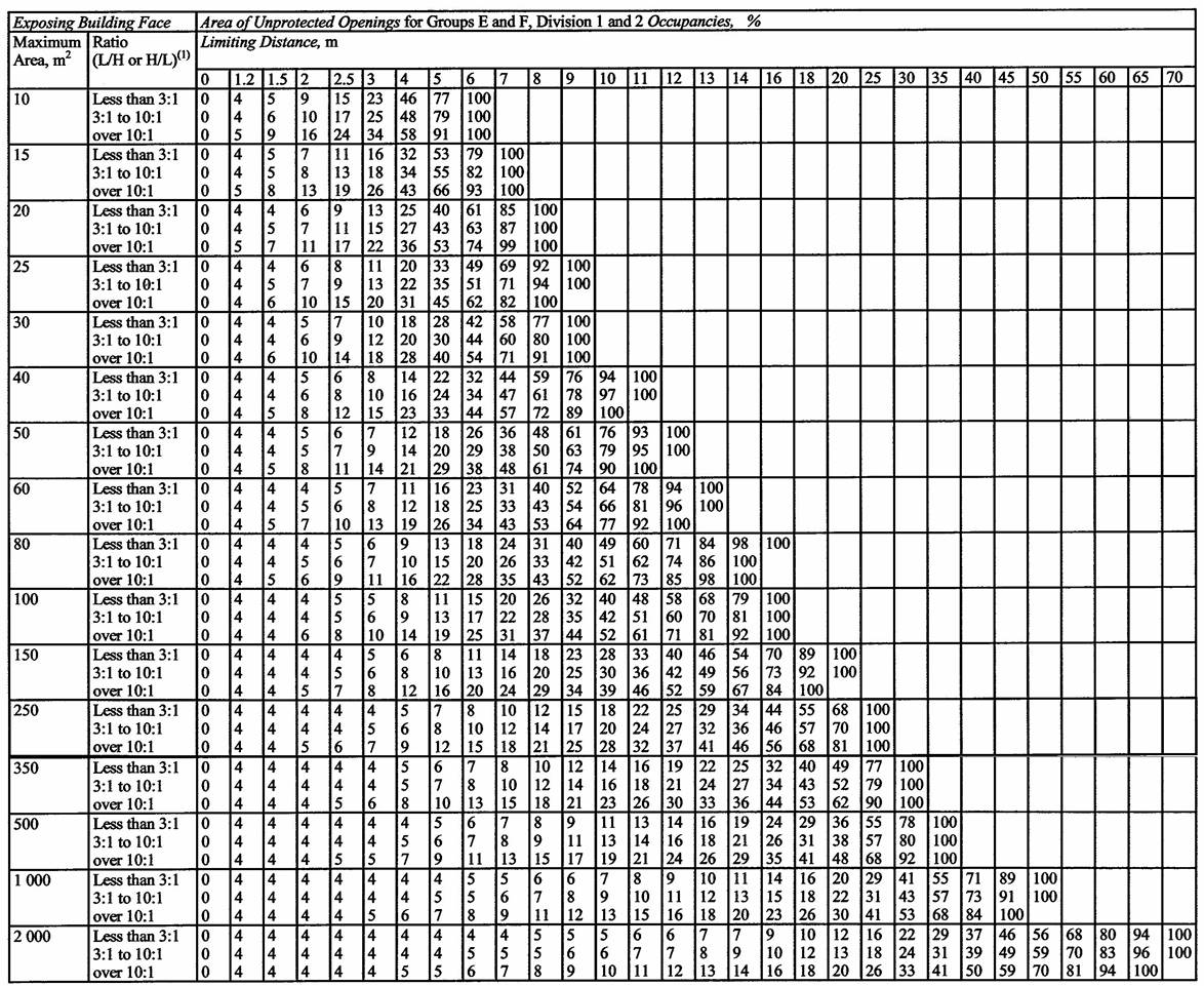
Notes to Table 3.2.3.1.C.:
(1) Apply whichever is greater,
L = Length of exposing building face,
H = Height of exposing building face.
Table 3.2.3.1.D.
Unprotected Opening Limits for a Building or Fire Compartment that is Sprinklered
Forming Part of Article 3.2.3.1.
| Item | Exposing Building Face | Area of Unprotected Opening for Groups A, B, C, D and F, Division 3 Occupancies, % |
| ||||||||||
|
| Maximum Area, m2 | Limiting Distance, m |
|
|
|
|
|
|
|
|
| ||
|
|
| 0 | 1.2 | 1.5 | 2 | 2.5 | 3 | 4 | 5 | 6 | 7 | 8 | 9 |
| 1, | 10 | 0 | 16 | 24 | 42 | 66 | 100 |
|
|
|
|
|
|
| 2. | 15 | 0 | 16 | 20 | 34 | 50 | 74 | 100 |
|
|
|
|
|
| 3. | 20 | 0 | 16 | 20 | 30 | 42 | 60 | 100 |
|
|
|
|
|
| 4. | 25 | 0 | 16 | 18 | 26 | 38 | 52 | 90 | 100 |
|
|
|
|
| 5. | 30 | 0 | 14 | 18 | 24 | 34 | 46 | 78 | 100 |
|
|
|
|
| 6. | 40 | 0 | 14 | 16 | 22 | 30 | 40 | 64 | 96 | 100 |
|
|
|
| 7. | 50 | 0 | 14 | 16 | 20 | 28 | 36 | 56 | 82 | 100 |
|
|
|
| 8. | 60 | 0 | 14 | 16 | 20 | 26 | 32 | 50 | 72 | 98 | 100 |
|
|
| 9. | 80 | 0 | 14 | 16 | 18 | 22 | 28 | 42 | 58 | 80 | 100 |
|
|
| 10. | 100 | 0 | 14 | 16 | 18 | 22 | 26 | 36 | 50 | 68 | 88 | 100 |
|
| 11. | 150 or more | 0 | 14 | 14 | 16 | 20 | 22 | 30 | 40 | 52 | 66 | 82 | 100 |
Table 3.2.3.1.E.
Unprotected Opening Limits for a Building or Fire Compartment that is Sprinklered
Forming Part of Article 3.2.3.1.
| Item | Exposing Building Face | Area of Unprotected Opening for Groups E and F, Division 1 and 2 Occupancies, % |
|
| |||||||||||||||
|
| Maximum Area, m2 | Limiting Distance, m |
|
|
|
|
|
|
|
|
|
|
|
|
| ||||
|
|
| 0 | 1.2 | 1.5 | 2 | 2.5 | 3 | 4 | 5 | 6 | 7 | 8 | 9 | 10 | 11 | 12 | 13 | 14 | 15 |
| 1. | 10 | 0 | 8 | 12 | 20 | 34 | 50 | 96 | 100 |
|
|
|
|
|
|
|
|
|
|
| 2. | 15 | 0 | 8 | 10 | 16 | 26 | 36 | 68 | 100 |
|
|
|
|
|
|
|
|
|
|
| 3. | 20 | 0 | 8 | 10 | 14 | 22 | 30 | 54 | 86 | 100 |
|
|
|
|
|
|
|
|
|
| 4. | 25 | 0 | 8 | 10 | 14 | 18 | 26 | 44 | 70 | 100 |
|
|
|
|
|
|
|
|
|
| 5. | 30 | 0 | 8 | 8 | 12 | 18 | 24 | 40 | 60 | 88 | 100 |
|
|
|
|
|
|
|
|
| 6. | 40 | 0 | 8 | 8 | 12 | 16 | 20 | 32 | 48 | 68 | 94 | 100 |
|
|
|
|
|
|
|
| 7. | 50 | 0 | 8 | 8 | 10 | 14 | 18 | 28 | 40 | 58 | 76 | 100 |
|
|
|
|
|
|
|
| 8. | 60 | 0 | 8 | 8 | 10 | 12 | 16 | 24 | 36 | 50 | 66 | 86 | 100 |
|
|
|
|
|
|
| 9. | 80 | 0 | 8 | 8 | 10 | 12 | 14 | 20 | 30 | 40 | 52 | 66 | 84 | 100 |
|
|
|
|
|
| 10. | 100 | 0 | 8 | 8 | 8 | 10 | 12 | 18 | 26 | 34 | 44 | 56 | 70 | 84 | 100 |
|
|
|
|
| 11. | 150 | 0 | 8 | 8 | 8 | 10 | 12 | 16 | 20 | 26 | 32 | 40 | 50 | 60 | 72 | 84 | 98 | 100 |
|
| 12. | 200 or more | 0 | 8 | 8 | 8 | 8 | 10 | 14 | 18 | 22 | 28 | 34 | 42 | 50 | 60 | 68 | 80 | 92 | 100 |
3.2.3.2. Area of Exposing Building Face
(1) Except as permitted by Sentences (2), and (3), the area of an exposing building face shall be calculated as the total area of exterior wall facing in one direction on any side of a building measured from the finished ground level to the uppermost ceiling.
(2) If a building is divided by fire separations into fire compartments, the area of exposing building face is permitted to be calculated for each fire compartment provided the fire separations have a fire-resistance rating not less than 45 min.
(3) In a building that contains an interconnected floor space, the area of the exposing building face for the interconnected floor space is permitted to be determined by considering each storey as a separate fire compartment notwithstanding openings through the floor assemblies.
3.2.3.3. Wall Enclosing Attic or Roof Space
(1) An exterior wall enclosing an attic or roof space and located above an exposing building face, shall be constructed in conformance with the requirements for the exposing building face.
3.2.3.4. Reserved
3.2.3.5. Wall with Limiting Distance Less Than 1.2 m
(1) Openings in a wall that has a limiting distance less than 1.2 m shall be protected by closures whose fire-protection rating is in conformance with the fire-resistance rating required for the wall.
(2) Wired glass or glass block shall not be used for a closure referred to in Sentence (1).
3.2.3.6. Combustible Projections
(1) Except for a building containing one or two dwelling units only, combustible projections on the exterior of a wall that could expose an adjacent building to fire spread and are more than 1 m above ground level, including balconies, platforms, canopies and stairs, shall not be permitted within,
(a) 1.2 m of a property line or the centre line of a public way, or
(b) 2.4 m of a combustible projection on another building on the same property.
(2) Except as provided in Sentence (3.1), where the exposing building face has a limiting distance of not more than 0.45 m, projecting roof soffits shall not be constructed above the exposing building face.
(3) Except as provided in Sentence (3.1), where the exposing building face has a limiting distance of more than 0.45 m, the face of roof soffits above the exposing building face shall not project to less than 0.45 m from the property line.
(3.1) Subject to Sentence (4), the face of a roof soffit is permitted to project to the property line, where it faces a street, lane or public thoroughfare.
(4) Where roof soffits project to less than 1.2 m from the centre line of a lane or public thoroughfare or from an imaginary line between two buildings or fire compartments on the same property, they shall,
(a) have no openings, and
(b) be protected by,
(i) not less than 0.38 mm thick sheet steel,
(ii) unvented aluminum conforming to CAN/CGSB-93.2-M, “Prefinished Aluminum Siding, Soffits and Fascia, for Residential Use”,
(iii) not less than 12.7 mm thick gypsum soffit board or gypsum ceiling board installed according to CSA A82.31-M, “Gypsum Board Application”,
(iv) not less than 11 mm thick plywood,
(v) not less than 12.5 mm thick OSB or waferboard, or
(vi) not less than 11 mm thick lumber.
(5) For buildings of combustible construction, materials installed to provide the required protection of soffits may be covered with a combustible or noncombustible finish material.
3.2.3.7. Construction of Exposing Building Face
(1) Except as provided by Sentences (3) to (5) and Articles 3.2.3.10. and 3.2.3.11, the fire-resistance rating, construction and cladding for exposing building faces of buildings or fire compartments shall comply with Table 3.2.3.7.
(2) Reserved
(3) Except as provided by Sentences (4) and (5) and Articles 3.1.4.8. and 3.1.6.9., cladding for buildings or fire compartments where the maximum permitted area of unprotected openings is more than 10% of the exposing building face need not be noncombustible where the wall assembly complies with the requirements of Sentence 3.1.5.5.(1) when tested in conformance with CAN/ULC-S134, “Fire Test of Exterior Wall Assemblies”.
(4) Except as provided by Articles 3.1.4.8. and 3.1.6.9., cladding for buildings or fire compartments where the maximum permitted area of unprotected openings is more than 10% but not more than 25% of the exposing building face need not be noncombustible where the wall assembly complies with Article 3.1.5.5.
(5) Except as provided by Articles 3.1.4.8. and 3.1.6.9., cladding for buildings or fire compartments where the maximum permitted area of unprotected openings is more than 25% but not more than 50% of the exposing building face need not be noncombustible where,
(a) the limiting distance is greater than 5 m,
(b) the building or fire compartment and all combustible attic or roof spaces are sprinklered,
(c) the cladding,
(i) conforms to Subsection 9.27.6., 9.27.7., 9.27.8., 9.27.9. or 9.27.10.,
(ii) is installed without furring members, or on furring not more than 25 mm thick, over gypsum sheathing at least 12.7 mm thick or over masonry, and
(iii) after conditioning in conformance with ASTM D2898, “Accelerated Weathering of Fire-Retardant-Treated Wood for Fire Testing”, has a flame-spread rating not greater than 25 on the exterior face when tested in accordance with Sentence 3.1.12.1.(1),
(d) the cladding,
(i) conforms to Subsection 9.27.12.,
(ii) is installed with or without furring members over gypsum sheathing at least 12.7 mm thick or over masonry,
(iii) has a flame-spread rating not greater than 25 when tested in accordance with Sentence 3.1.12.1.(2), and
(iv) does not exceed 2 mm in thickness exclusive of fasteners, joints and local reinforcements, or
(e) the wall assembly complies with Article 3.1.5.5.
(6), (7) Revoked: O. Reg. 89/23, s. 9 (5).
(8) The construction requirements for the exposing building face that are listed in Table 3.2.3.7. shall be satisfied before the area of unprotected openings may be increased as permitted by Sentence 3.2.3.12.(1).
Table 3.2.3.7.
Minimum Construction Requirements for Exposing Building Faces
Forming Part of Sentences 3.1.6.9.(5) and 3.2.3.7.(1) and (8)
| Column 1 | Column 2 | Column 3 | Column 4 | Column 5 | Column 6 |
| 1. | Group A, B, C, D, or Group F, Division 3 | 0 to 10 | 1h | Noncombustible | Noncombustible |
| 2. | Group A, B, C, D, or Group F, Division 3 | > 10 to 25 | 1h | Combustible, Encapsulated Mass Timber Construction, or Noncombustible | Noncombustible |
| 3. | Group A, B, C, D, or Group F, Division 3 | > 25 to 50 | 45 min | Combustible, Encapsulated Mass Timber Construction, or Noncombustible | Noncombustible |
| 4. | Group A, B, C, D, or Group F, Division 3 | > 50 to < 100 | 45 min | Combustible, Encapsulated Mass Timber Construction, or Noncombustible | Combustible or Noncombustible(1)(2) |
| 5. | Group E, or Group F, Division 1 or 2 | 0 to 10 | 2 h | Noncombustible | Noncombustible |
| 6. | Group E, or Group F, Division 1 or 2 | > 10 to 25 | 2 h | Combustible, Encapsulated Mass Timber Construction, or Noncombustible | Noncombustible |
| 7. | Group E, or Group F, Division 1 or 2 | > 25 to 50 | 1 h | Combustible, Encapsulated Mass Timber Construction, or Noncombustible | Noncombustible |
| 8. | Group E, or Group F, Division 1 or 2 | > 50 to < 100 | 1 h | Combustible, Encapsulated Mass Timber Construction, or Noncombustible | Combustible or Noncombustible(1)(2) |
Notes to Table 3.2.3.7.:
(1) The cladding on Group C buildings within the scope of Article 3.2.2.43A. and on Group D buildings within the scope of Article 3.2.2.50A. shall be noncombustible or consist of a wall that satisfies the requirements of Article 3.1.4.8.
3.2.3.8. Protection of Exterior Building Face
(1) Except as permitted by Sentence (3) and in addition to the requirements of Sentence 3.2.3.7.(1) and where the maximum permitted area of unprotected openings is greater than 10% of the exposing building face, foamed plastic insulation used in an exterior wall of a building more than 3 storeys in building height shall be protected on its exterior surface by,
(a) concrete or masonry not less than 25 mm thick, or
(b) noncombustible material that complies with the criteria for testing and conditions of acceptance of Sentence (2) when tested in conformance with CAN/ULC-S101, “Fire Endurance Tests of Building Construction and Materials”.
(2) The criteria for testing and the conditions of acceptance for a wall assembly to satisfy the requirements of Clause (1)(b) are that,
(a) the fire exposed area of the wall assembly shall be not less than 9.3 m2 and have no dimension less than 2.75 m,
(b) the exposed surface will include typical vertical and horizontal joints,
(c) the test shall be continued for not less than 15 min and the standard time/temperature curve of the referenced standard shall be followed,
(d) the noncombustible protective material will remain in place and no through openings will develop that are visible when viewed normal to the face of the material, and
(e) the noncombustible protective material will not disintegrate in a manner that would permit fire to propagate along the surface of the test assembly.
(3) The requirements of Sentence (1) are waived for wall assemblies that comply with the requirements of Article 3.1.5.5.
3.2.3.9. Protection of Structural Members
(1) Structural members, including beams, columns and arches, placed wholly or partly outside an exterior face of a building that are less than 3 m from the property line or centreline of a public thoroughfare shall be protected from exterior fire by fire protection having a fire-resistance rating not less than that required by Articles 3.2.2.20. to 3.2.2.83. for their protection from interior fires, but not less than 1 h.
(2) Structural members of heavy timber construction, including beams, columns and arches, placed wholly or partly outside an exterior face of a building and 3 m or more from the property line or centreline of a public thoroughfare need not be covered with noncombustible cladding.
3.2.3.10. Unlimited Unprotected Openings
(1) An exposing building face of an open-air storey in a storage garage is permitted to have unlimited unprotected openings provided it has a limiting distance not less than 3 m.
(2) The exposing building face of a storey that faces a street and is at the same level as the street is permitted to have unlimited unprotected openings if the limiting distance is not less than 9 m.
3.2.3.11. Low Fire Load, 1 Storey Building
(1) An exposing building face of a building of low hazard industrial occupancy conforming to Article 3.2.2.82. is permitted to be of noncombustible construction without a fire-resistance rating provided,
(a) it is not a loadbearing wall, and
(b) the limiting distance is not less than 3 m.
3.2.3.12. Area Increase for Unprotected Openings
(1) Except as required by Sentence 3.2.3.7.(8), the maximum area of unprotected openings in any exposing building face or fire compartment of a building that is not sprinklered is permitted to be doubled if the openings are glazed with,
(a) glass block conforming to the requirements of Article 3.1.8.14., or
(b) wired glass assemblies conforming to MMAH Supplementary Standard SB-2, “Fire Performance Ratings”.
3.2.3.13. Protection of Exit Facilities
(1) Except as required by Sentence (3) and as permitted by Sentence 3.4.4.3.(1), if the plane of an exterior wall of an exit enclosure forms an angle less than 135° with the plane of an exterior wall of the building it serves, and an opening in the exterior wall of the exit enclosure could be exposed to fire from an opening in the exterior wall of the building, the opening in either the exterior wall of the exit or the exterior wall of the building shall be protected in conformance with the requirements of Sentence (4) where the opening in the exterior wall of the building is within 3 m horizontally and,
(a) less than 10 m below an opening in the exterior wall of the exit, or
(b) less than 2 m above an opening in the exterior wall of the exit.
(2) If an unenclosed exterior exit stair or ramp could be exposed to fire from an opening in the exterior wall of the building it serves, the opening in the exterior wall of the building shall be protected in conformance with the requirements of Sentence (4) where the opening in the exterior wall of the building is within 3 m horizontally and,
(a) less than 10 m below the exit stair or ramp, or
(b) less than 5 m above the exit stair or ramp.
(3) Except as permitted by Sentence 3.4.4.3.(1), if an exterior exit door in one fire compartment is within 3 m horizontally of an opening in another fire compartment and the exterior walls of these fire compartments intersect at an exterior angle of less than 135°, the opening shall be protected in conformance with the requirements of Sentence (4).
(4) The opening protection referred to in Sentences (1) to (3) shall consist of,
(a) glass block conforming to the requirements of Article 3.1.8.14.,
(b) a wired glass assembly conforming to MMAH Supplementary Standard SB-2, “Fire Performance Ratings”, or
(c) a closure conforming to the requirements of Subsection 3.1.8. and Articles 3.2.3.1. and 3.2.3.14.
3.2.3.14. Wall Exposed to Another Wall
(1) Except as required by Sentences (3) and 3.2.3.13.(1) or as permitted by Sentence 3.2.3.19.(4), if an unprotected opening in an exterior wall of a fire compartment is exposed to an unprotected opening in the exterior wall of another fire compartment, and the planes of the two walls are parallel or at an angle less than 135°, measured from the exterior of the building, the unprotected openings in the two fire compartments shall be separated by a distance not less than DO,
where,
DO = 2D – [(θ/90) × D] but in no case less than 1 m, and
D = the greater required limiting distance for the exposing building faces of the two fire compartments, and
θ = the angle made by the intersecting planes of the exposing building faces of the two fire compartments (in the case where the exterior walls are parallel and face each other, θ = 0°).
(2) The exterior wall of each fire compartment referred to in Sentence (1) within the distance, DO, shall have a fire-resistance rating not less than that required for the interior vertical fire separation between the fire compartment and the remainder of the building.
(3) Sentence (1) does not apply to unprotected openings of fire compartments within a building that is sprinklered, but shall apply to,
(a) unprotected openings of fire compartments on opposite sides of a firewall, and
(b) exposure from unprotected openings of a fire compartment that is not protected by an automatic sprinkler system.
3.2.3.15. Wall Exposed to Adjoining Roof
(1) Except as permitted by Sentence 3.2.3.19.(4), if a wall in a building is exposed to a fire hazard from an adjoining roof of a separate fire compartment that is not sprinklered in the same building, and the exposed wall contains windows within 3 storeys vertically and 5 m horizontally of the roof, the roof shall contain no skylights within 5 m of the exposed wall.
3.2.3.16. Protection of Soffits
(1) Except as permitted by Sentences (2) to (4), where a common attic or roof space spans more than two suites of residential occupancy or more than two patients’ or residents’ sleeping rooms in a Group B, Division 2 or 3 occupancy, and the common attic or roof space projects beyond the exterior wall of the building, the portion of any soffit or other surface enclosing the projection that is less than 2.5 m vertically above a window or door and less than 1.2 m from either side of the window or door, shall have no openings and shall be protected by,
(a) noncombustible material,
(i) not less than 0.38 mm thick, and
(ii) having a melting point not below 650°C,
(b) not less than 12.7 mm thick gypsum soffit board or gypsum wallboard installed according to CSA A82.31-M, “Gypsum Board Application”,
(c) not less than 11 mm thick plywood,
(d) not less than 12.5 mm thick OSB or waferboard, or
(e) not less than 11 mm thick lumber.
(2) Where an attic or roof space, including its adjoining eave overhangs, is separated by construction conforming to Article 3.1.11.7. into compartments such that the resulting spaces are not common to more than two suites of residential occupancy or more than two patients’ or residents’ sleeping rooms in a Group B, Division 2 or 3 occupancy, the requirements in Sentence (1) do not apply.
(3) If an eave overhang is completely separated from the remainder of the attic or roof space by fire blocks, the requirements of Sentence (1) do not apply.
(4) The protection required by Sentence (1) for projections is permitted to be omitted if,
(a) the fire compartments behind the window and door openings are sprinklered in accordance with Article 3.2.5.13., and
(b) all rooms, including closets and bathrooms, having openings in the wall beneath the soffit are sprinklered, notwithstanding exceptions permitted in the standards referenced in Article 3.2.5.13. for the installation of automatic sprinkler systems.
3.2.3.17. Canopy Protection for Vertically Separated Openings
(1) Except as permitted by Sentences (2) and (3), if a storey classified as a Group E or Group F, Division 1 or 2 major occupancy is required to be separated from the storey above by a fire separation,
(a) every opening in the exterior wall of the lower storey that is located vertically below an opening in the storey above shall be separated from the storey above by a canopy projecting not less than 1 m from the face of the building at the intervening floor level, and
(b) the canopy required by Clause (a) shall have a fire-resistance rating not less than that required for the floor assembly but need not be more than 1 h, except as required elsewhere in this Subsection.
(2) Except as permitted by Sentence (3), the canopy required by Sentence (1) is permitted to be omitted if the exterior wall of the upper storey is recessed not less than 1 m behind the exterior wall containing the opening in the lower storey.
(3) The requirements of Sentences (1) and (2) are permitted to be waived if sprinklers are installed in,
(a) the lower storey referred to in Clause (1)(a), and
(b) the storey immediately above the lower storey.
3.2.3.18. Covered Vehicular Passageway
(1) A covered vehicular passageway designed as a receiving or shipping area shall be separated from every building or part of a building adjoining it by a fire separation having a fire-resistance rating not less than 1.5 h.
(2) A covered vehicular passageway constructed below grade shall be of noncombustible construction.
3.2.3.19. Walkway between Buildings
(1) Except as required by Sentence 3.2.3.20.(2), if buildings are connected by a walkway, each building shall be separated from the walkway by a fire separation with a fire-resistance rating not less than 45 min.
(2) Except as permitted by Sentence (3), a walkway connected to a building required to be of noncombustible construction shall also be of noncombustible construction.
(2.1) Except as provided in Sentence (3), a walkway connected to a building or part of a building permitted to be of encapsulated mass timber construction shall be of noncombustible construction or encapsulated mass timber construction.
(3) A walkway connected to a building required to be of noncombustible construction or to a building or part of a building permitted to be of encapsulated mass timber construction is permitted to be of heavy timber construction provided,
(a) not less than 50% of the area of any enclosing perimeter walls is open to the outdoors, and
(b) the walkway is at ground level.
(4) A walkway of noncombustible construction used only as a pedestrian thoroughfare need not conform to the requirements of Articles 3.2.3.14. and 3.2.3.15.
(5) A walkway between buildings shall be not more than 9 m wide.
3.2.3.20. Underground Walkway
(1) An underground walkway shall not be designed or used for any purpose other than pedestrian travel unless,
(a) the purpose is permitted, and
(b) sprinklers are installed in any space in the walkway containing an occupancy.
(2) Buildings connected by an underground walkway shall be separated from the walkway by a fire separation with a fire-resistance rating not less than 1 h.
(3) An underground walkway shall be of noncombustible construction suitable for an underground location.
(4) In an underground walkway,
(a) smoke barrier doors shall be installed at intervals of not more than 100 m, or
(b) the travel distance from the door of an adjacent room or space to the nearest exit shall be not more than one and a half times the least allowable travel distance to an exit for any of the adjacent occupancies as permitted by Sentence 3.4.2.5.(1).
(5) An underground walkway between buildings shall be not more than 9 m wide.
3.2.3.21. Service Lines under Buildings
(1) A building shall not be constructed over an existing buried flammable gas main unless the gas main is encased in a gas-tight conduit in conformance with CAN/CSA-Z662, “Oil and Gas Pipeline Systems”.
3.2.4. Fire Alarm and Detection Systems
3.2.4.1. Determination of Requirement for a Fire Alarm System
(1) Reserved
(2) Except as permitted by Sentences (3) to (5) and Sentence 3.2.4.2.(4), a fire alarm system shall be installed in a building that contains,
(a) a contained use area,
(b) an impeded egress zone,
(c) more than 3 storeys, including storeys below the first storey,
(d) a total occupant load more than 300, other than in open air seating areas,
(e) an occupant load more than 150 above or below the first storey, other than in open air seating areas,
(f) a school, college or child care facility, with an occupant load more than 40,
(g) a licensed beverage establishment or a restaurant, with an occupant load more than 150,
(h) a low hazard industrial occupancy with an occupant load more than 75 above or below the first storey,
(h.1) a medium hazard industrial occupancy with an occupant load more than 75 above or below the first storey,
(i) a residential occupancy with sleeping accommodation for more than 10 persons,
(j) a high hazard industrial occupancy with an occupant load more than 25,
(k) an occupant load more than 300 below an open air seating area,
(l) an interconnected floor space required to conform to Articles 3.2.8.3. to 3.2.8.11,
(m) a care and treatment occupancy for more than 10 persons receiving care or treatment, or
(n) a care occupancy for more than 10 persons receiving care.
(3) If each dwelling unit has direct access to an exterior exit facility leading to ground level, a fire alarm system is not required in an apartment building,
(a) in which not more than four dwelling units share a common means of egress, or
(b) that is not more than 3 storeys in building height.
(4) A fire alarm system is not required in a hotel 3 storeys or less in building height provided each suite has direct access to an exterior exit facility leading to ground level.
(5) A fire alarm system is not required in a storage garage conforming to Article 3.2.2.83. provided there are no other occupancies in the building.
3.2.4.2. Continuity of Fire Alarm System
(1) Except as permitted by Sentence (6), if there are openings through a firewall, other than those for piping, tubing, wiring and totally enclosed noncombustible raceways, the requirements in this Subsection shall apply to the floor areas on both sides of the firewall as if they were in the same building.
(2) Except as permitted by Sentence (4), if a building contains more than one major occupancy and a fire alarm system is required, a single system shall serve all occupancies.
(3) Except as permitted by Sentence (4), if a fire alarm system is required in any portion of a building, it shall be installed throughout the building.
(4) Except as required by Sentence (5), the requirements in this Subsection are permitted to be applied to each portion of a building not more than 3 storeys in building height, in which a vertical fire separation having a fire-resistance rating not less than 1 h separates the portion from the remainder of the building as if it were a separate building, provided there are no openings through the fire separation, other than those for piping, tubing, wiring and totally enclosed noncombustible raceways.
(5) The permission in Sentence (4) to consider separated portions of a building as separate buildings does not apply to service rooms and storage rooms.
(6) Buildings interconnected by walkways permitted in Articles 3.2.3.19. and 3.2.3.20. or by vestibules provided in conformance with Article 3.2.6.3. shall be treated as separate buildings for the purpose of fire alarm installation required by this Subsection.
3.2.4.3. Types of Fire Alarm Systems
(1) A fire alarm system shall be,
(a) a single stage system in a Group F, Division 1 occupancy,
(b) a two stage system in a Group B occupancy other than those described in Clause (c),
(c) a single or two stage system in a building 3 storeys or less in building height that contains a Group B, Division 3 occupancy,
(d) a single stage system in elementary and secondary schools, except for a special needs facility, and
(e) a single or two stage system in all other cases.
3.2.4.4. Description of Fire Alarm Systems
(1) A single stage fire alarm system shall, upon the operation of any manual pull station or fire detector, cause an alarm signal to sound on all audible signal devices in the system.
(2) A two stage fire alarm system shall,
(a) cause an alert signal to sound upon the operation of any manual pull station or fire detector,
(b) except for a Group B, Division 2 occupancy, automatically cause an alarm signal to sound if the alert signal is not acknowledged within 5 min of its initiation,
(c) have each manual pull station equipped so that the use of a key or other similar device causes an alarm signal to sound and continue to sound upon the removal of the key or similar device from the manual pull station, and
(d) in a building containing a hotel,
(i) cause an alarm signal to sound in the initiating fire zone in the hotel, and
(ii) cause an alert signal to sound throughout the hotel and such parts of the building as is necessary to alert hotel staff.
(3) A two stage fire alarm system is permitted to be zone coded so that, upon the operation of any manual pull station or fire detector,
(a) a coded alert signal is sounded indicating the zone of alarm initiation,
(b) the coded alert signal is repeated in its entirety no fewer than four times, and
(c) a continuous alert signal is sounded upon completion of the coded signals referred to in Clause (b) and Sentence (4).
(4) If a second manual pull station or fire detector is operated in a fire alarm system with zone coding as permitted by Sentence (3), in a zone other than that for which the first alert signal was sounded, the coded alert signal for the first zone shall be completed before the coded alert signal for the second zone is repeated no fewer than four times.
3.2.4.5. Installation and Verification of Fire Alarm Systems
(1) Fire alarm systems, including those with voice communication capability, shall be installed in conformance with CAN/ULC-S524, “Installation of Fire Alarm Systems”.
(2) A fire alarm system shall be verified in conformance with CAN/ULC-S537, “Verification of Fire Alarm Systems”, to ensure satisfactory operation.
3.2.4.6. Reserved
3.2.4.7. Silencing of Alarm Signals
(1) Except as permitted by Sentence (3), a fire alarm system shall be designed so that when an alarm signal is actuated it cannot be silenced automatically before a period of time has elapsed that is not less than,
(a) 5 min for a building not required to be equipped with an annunciator, and
(b) 20 min for any other building.
(2) Except as permitted by Sentences 3.2.4.20.(9) and 3.2.4.23.(2) and (3), a fire alarm system shall not incorporate manual silencing switches other than those installed inside the fire alarm control unit.
(3) Except as provided by Clause 3.2.4.23.(3)(a), in a care and treatment occupancy an alert signal is permitted to be silenced automatically after 1 min.
3.2.4.8. Signals to Fire Department
(1) If a fire alarm system is required to be installed and a single stage system is provided, the system shall be designed to notify the fire department in conformance with Sentence (4) that an alarm signal has been initiated in,
(a) a Group A occupancy having an occupant load more than 300,
(b) a Group B occupancy,
(c) a Group F, Division 1 occupancy,
(d) a building regulated by the provisions of Subsection 3.2.6.,
(e) a building containing interconnected floor space required to conform to Articles 3.2.8.3. to 3.2.8.11., or
(f) a retirement home.
(2) A fire alarm system that includes waterflow indicating devices shall be designed to notify the fire department, in conformance with Sentence (4), that an alarm has been initiated.
(3) If a fire alarm system is required to be installed and a two stage system is provided, the system shall be designed to notify the fire department, in conformance with Sentence (4), that an alert signal has been initiated.
(4) Notification of the fire department required by Sentences (1) to (3) shall be by way of,
(a) signals to a central station conforming to CAN/ULC-S561, “Installation and Services for Fire Signal Receiving Centres and Systems”, or
(b) the municipal fire alarm system.
(5) Where a single stage fire alarm system is installed in a building that is not sprinklered, and Sentence (1) does not apply, a legible notice, that is not easily removed, shall be affixed to the wall near each manual pull station stating,
(a) that the fire department is to be notified in the event of a fire emergency, and
(b) the emergency telephone number for the municipality or the telephone number of the fire department.
3.2.4.9. Annunciator and Zone Indication
(1) Except as permitted by Sentences (3) to (5), an annunciator shall be installed in close proximity to a building entrance that faces a street or an access route for fire department vehicles that complies with Sentence 3.2.5.5.(1).
(2) Except as permitted by Sentence (6), the annunciator required by Sentence (1) shall have separate zone indication of the actuation of the alarm initiating devices in each,
(a) floor area so that in a building that is not sprinklered, the area of coverage for each zone is neither more than,
(i) 1 storey, nor
(ii) 2 000 m2,
(b) floor area so that in a building that is sprinklered, the area of coverage for each zone is neither more than,
(i) 1 storey, nor
(ii) the system area limits as specified in NFPA 13, “Installation of Sprinkler Systems”,
(c) shaft required to be equipped with fire detectors,
(d) air handling system required to be equipped with smoke detectors,
(e) fire extinguishing system required by NFPA 96, “Ventilation Control and Fire Protection of Commercial Cooking Operations”,
(f) contained use area,
(g) impeded egress zone,
(h) fire compartment required by Sentence 3.3.3.5.(2) or Sentence 3.3.4.11.(2), and
(i) fire compartment required to be separated by vertical fire separations having a fire-resistance rating not less than 2 h, other than dwelling units described in Subsection 3.3.4.
(3) An annunciator need not be provided for a fire alarm system if not more than one zone indicator is required in Sentence (2).
(4) If an annunciator is not installed as part of a fire alarm system in conformance with Sentence (1), a visual and audible trouble signal device shall be provided inside the main entrance of the building.
(5) The requirements in Sentence (1) are waived in a building,
(a) Reserved
(b) that has an aggregate area for all storeys of not more than 2 000 m2, and
(c) that is not more than 3 storeys in building height.
(6) The area limits of Clause (2)(a) are waived for an interior undivided open space used as an arena, a rink or a swimming pool provided that other spaces in the building that are separated from the open space are individually zoned in accordance with the requirements of Sentence (2).
(7) A fire alarm control unit installed in close proximity to a building entrance that faces a street or an access route for fire department vehicles that complies with Sentence 3.2.5.5.(1), is deemed to satisfy the requirement for an annunciator provided all indicators required for an annunciator or trouble signal device are included on the control unit.
(8) In a building containing a hotel in which a trouble signal sounding device has a silencing switch, a trouble light shall be installed in,
(a) the main reception area serving the hotel, or
(b) another continually-supervised location.
(9) In a long-term care home, a remote audiovisual fire alarm trouble signal shall be located at the main nursing station.
3.2.4.10. Electrical Supervision
(1) Electrical supervision shall be provided for a fire alarm system.
(2) If a fire alarm system in a building is required by Sentence 3.2.4.9.(1) to have an annunciator, each valve controlling water supplies in a standpipe system, except for hose valves, shall be equipped with an electrically supervised switch for transmitting a trouble signal to the annunciator in the event of movement of the valve handle.
(3) If a fire alarm system is installed in a building, an automatic sprinkler system shall be electrically supervised to indicate a supervisory signal on the building fire alarm system annunciator for each of the following,
(a) movement of a valve handle that controls the supply of water to sprinklers,
(b) loss of excess water pressure required to prevent false alarms in a wet pipe system,
(c) loss of air pressure in a dry pipe system,
(d) loss of air pressure in a pressure tank,
(e) a significant change in water level in any water storage container used for firefighting purposes,
(f) loss of power to any automatically starting fire pump, and
(g) a temperature approaching the freezing point in any dry pipe valve enclosure or water storage container used for firefighting purposes.
(4) If a fire alarm system is installed in a building, a fire pump shall be electrically supervised in accordance with NFPA 20, “Installation of Stationary Pumps for Fire Protection”.
(5) If a fire alarm system is required in a building, electrical supervision shall be provided to indicate, on the fire alarm system annunciator, a loss of power to a heat tracing cable that is installed to heat,
(a) a standpipe riser,
(b) a sprinkler line as part of a fire suppression system, or
(c) an exit or means of egress to keep it free of ice and snow.
(6) In a building regulated by the provisions of Subsection 3.2.6., the indication of a supervisory signal in accordance with Sentence (3) shall be transmitted to a proprietary control centre or to an independent central station.
3.2.4.11. Fire Detectors
(1) Fire detectors required by this Article shall be connected to the fire alarm system.
(2) Except as provided in Article 3.2.4.16., if a fire alarm system is required, fire detectors shall be installed in each,
(a) storage room not within a dwelling unit,
(b) service room not within a dwelling unit,
(c) janitors’ room,
(d) room in which hazardous substances are to be used or stored,
(e) elevator or dumbwaiter shaft,
(f) laundry room in a building of residential occupancy, but not one within a dwelling unit, and
(g) hazardous classroom and change room in an elementary or secondary school.
3.2.4.12. Smoke and Heat Detectors
(1) If a fire alarm system is required, smoke detectors shall be installed in,
(a) each sleeping room and each corridor serving as part of a means of egress from sleeping rooms in portions of a building classified as Group B major occupancy,
(b) each room in a contained use area and corridors serving those rooms,
(c) each corridor in portions of a building classified as Group A, Division 1 major occupancy,
(d) each public corridor in portions of a building classified as Group C major occupancy,
(e) each exit stair shaft,
(f) each corridor serving classrooms in elementary and secondary schools, and
(g) each elevator machine room or machinery space.
(2) Except as provided in Article 3.2.4.16., if a fire alarm system is required, heat detectors shall be installed in,
(a) every room in portions of buildings classified as Group A, Division 1,
(b) except in a hotel, in every suite, and every room not located within a suite, in portions of buildings classified as Group C major occupancy and more than 3 storeys in building height, and
(c) in a floor area containing a hotel, in every room in a suite and in every room not located in a suite other than washrooms within a suite, saunas, refrigerated areas and swimming pools.
(3) Smoke detectors required in sleeping rooms of care, care and treatment or detention occupancy shall upon actuation provide an audible and visible signal to staff serving those rooms so that the room or location containing the smoke detector can be easily identified.
(4) Smoke detectors required by Clause (1)(g) shall, upon actuation, recall the elevators served by machinery located in the machine room or machinery space in which the smoke detector is installed.
(5) Except as permitted by Sentences (6) and (7), where a building is required to be equipped with a fire alarm system, a smoke detector shall be located near the entrance to,
(a) a walkway described in Articles 3.2.3.19. and 3.2.3.20., or
(b) a vestibule provided in conformance with Article 3.2.6.3.
(6) Smoke detectors installed at the entrance to a walkway in conformance with Article 3.1.8.12. are deemed to meet the requirements of Sentence (5).
(7) Fire detectors are permitted to be installed in lieu of the smoke detectors required by Sentence (5) in Group F occupancies where the smoke detectors may be subjected to false alarms due to the activities within the building.
3.2.4.13. Prevention of Smoke Circulation
(1) If a fire alarm system is installed, an air handling system shall be designed to prevent the circulation of smoke upon a signal from a duct-type smoke detector if the air handling system,
(a) serves more than 1 storey,
(b) serves more than one suite in a storey,
(c) serves more than one fire compartment required by Sentence 3.3.3.5.(2) or Sentence 3.3.4.11.(2), or
(d) is not provided with fire dampers as permitted by Sentence 3.1.8.8.(4).
3.2.4.14. Vacuum Cleaning System Shutdown
(1) A central vacuum cleaning system serving more than one suite or storey in a building equipped with a fire alarm system shall be designed to shut down upon actuation of the fire alarm system.
3.2.4.15. Elevator Emergency Return
(1) Except as permitted by Sentence (3), in a building having elevators that serve storeys above the first storey and that are equipped with an automatic emergency recall feature, smoke detectors shall be installed in the elevator lobbies on the recall level so that when these smoke detectors are actuated, the elevators will automatically return directly to an alternate floor level.
(2) Smoke detectors required by Sentence (1) shall be designed as part of the building fire alarm system.
(3) The alternate floor recall feature required by Sentence (1) is not required if the floor area containing the recall level is sprinklered.
3.2.4.16. Sprinklers in Lieu of Fire Detectors
(1) Fire detectors required by Article 3.2.4.11. and heat detectors required by Sentence 3.2.4.12.(2) need not be provided within a floor area if the floor area is sprinklered and the sprinkler system is electrically supervised in conformance with Sentence 3.2.4.10.(3).
3.2.4.17. System Monitoring
(1) An automatic sprinkler system shall be equipped with waterflow detecting devices and, if an annunciator is required by Article 3.2.4.9., shall be installed so that each device serves,
(a) not more than 1 storey, and
(b) an area on each storey that is not more than the system area limits as specified in NFPA 13, “Installation of Sprinkler Systems”.
(2) If a fire alarm system is provided, waterflow indicating devices required by Sentence (1) shall be connected to the fire alarm system so that on actuation an alert signal or an alarm signal is initiated.
3.2.4.18. Manual Pull Stations
(1) Except as permitted by Sentences (2) and (3), if a fire alarm system is installed, a manual pull station shall be installed,
(a) near the principal entrance to the building, and
(b) near every required exit.
(2) In a building that is sprinklered, a manual pull station is not required at an exterior egress doorway from a suite that does not lead to an interior shared means of egress in a hotel not more than 3 storeys in building height, provided each suite is served by an exterior exit facility leading directly to ground level.
(3) In a building that is sprinklered, a manual pull station is not required at an exterior egress doorway from a dwelling unit that does not lead to an interior shared means of egress in a building not more than 3 storeys in building height containing only dwelling units, provided each dwelling unit is served by an exterior exit facility leading directly to ground level.
(4) In a building referred to in Sentence (2) or (3), manual pull stations shall be installed near doorways leading from shared interior corridors to the exterior.
(5) In a building containing a hotel, a manual pull station shall be installed in the main reception area serving the hotel.
(6) Except as permitted by Sentence (3), in Group C apartment buildings other than retirement homes, if a pull station is not installed on a floor area in accordance with Sentence (1) or (4),
(a) a manual pull station shall be installed in every dwelling unit in the floor area near each egress door leading from the dwelling unit,
(b) smoke detectors shall be installed in the floor area in public corridors and stairwells, and
(c) fire detectors shall be installed in the floor area in all common public areas and in rooms not located within dwelling units.
(7) In floor areas where the manual pull stations are located in dwelling units, a legible sign stating FIRE ALARM PULL STATIONS LOCATED IN APARTMENT UNITS shall be posted near every exit in a public corridor.
(8) Key switch activated pull stations are permitted in an impeded egress zone and a contained use area in Group B, Division 1 and 2 occupancies.
3.2.4.19. Alert and Alarm Signals
(1) In a two stage fire alarm system described in Sentence 3.2.4.4.(2), the same audible signal devices are permitted to be used to sound the alert signals and the alarm signals.
(2) If audible signal devices with voice reproduction capabilities are intended for paging and similar voice message use, other than during a fire emergency, they shall be installed so that alert signals and alarm signals take priority over all other signals.
(3) Audible signal devices forming part of a fire alarm or voice communication system shall not be used for playing music or background noise.
(4) Except as permitted by Sentence (6), visual signal devices shall be installed in addition to audible signal devices,
(a) in a building or portion of a building intended for use primarily by persons with hearing impairment,
(b) in a public corridor serving a Group A, B, C, D or E occupancy,
(c) in a corridor used by the public and in a floor area or part of a floor area where the public may congregate in a Group A occupancy,
(d) in not less than 10% of the suites of a hotel or motel,
(e) in a washroom for public use described in Sentence 3.8.2.3.(2), (3), (4) or (6), and
(f) in the living space in a suite of residential occupancy in a Group C major occupancy apartment building.
(5) Visual signal devices are permitted to be installed in lieu of audible signal devices in the compartments referred to in Article 3.3.3.6.
(6) Visual signal devices required by Clauses (4)(b) and (c) are not required in,
(a) a classroom, and
(b) a Group B, Division 3 occupancy that contains sleeping accommodation for not more than 10 persons and not more than six occupants require assistance in evacuation in case of an emergency.
3.2.4.20. Audibility of Alarm Systems
(1) Except as permitted by Sentence 3.2.4.19.(5) and except as required by Clause 3.2.4.4.(2)(d), audible signal devices forming part of a fire alarm system shall be installed in a building so that,
(a) alarm signals are clearly audible throughout the floor area, and
(b) alert signals are clearly audible in continuously staffed locations and, where there are no continuously staffed locations, throughout the floor area.
(2) The sound pattern of an alarm signal shall conform to the temporal pattern defined in Clause 4.2 of International Standard ISO 8201, “Acoustics — Audible Emergency Evacuation Signal”.
(3) The sound patterns of alert signals shall be significantly different from the temporal patterns of alarm signals.
(4) In all normally occupied spaces, the fire alarm signal sound pressure level,
(a) shall be not more than 100 dBA when measured at a distance of 3 m from the device, or
(b) is permitted to be more than 100 dBA provided the sound pressure level measured 2 000 mm above floor level is not more than 100 dBA.
(5) The sound pressure level in a sleeping room from a fire alarm audible signal device shall be not less than 75 dBA in a building of residential occupancy when any intervening doors between the device and the sleeping room are closed.
(6) Except as required by Sentence (5), the sound pressure level from a fire alarm audible signal device in a floor area shall be not less than 10 dBA above the ambient noise level, but with a minimum value not less than 65 dBA.
(7) Fire alarm audible signal devices shall be supplemented by visual signal devices in any floor area in which,
(a) the ambient noise level is more than 87 dBA, or
(b) the occupants of the floor area,
(i) use ear protective devices,
(ii) are located within an audiometric booth, or
(iii) are located within sound insulated enclosures.
(8) Sentence (7) shall also apply in an assembly occupancy in which music and other sounds associated with performances could exceed 100 dBA.
(9) Except as permitted by Sentence (13), an audible signal device located within a dwelling unit shall incorporate a means that enables the device to be silenced for a period of not more than 10 min, after which the device shall restore to normal operation.
(10) Audible signal devices within a dwelling unit or a suite of residential occupancy shall be connected to the fire alarm system,
(a) in a manner such that a single open circuit at one device will not impair the operation of other audible signal devices on the same circuit that serve the other dwelling units or suites of residential occupancy, or
(b) on separate signal circuits that are not connected to the devices in any other dwelling unit, public corridor or suites of residential occupancy.
(11) In a building or part of it classified as a residential occupancy,
(a) separate circuits shall be provided for audible signal devices on each floor area, and
(b) audible signal devices within dwelling units or suites of residential occupancy shall be wired on separate signal circuits from those not within suites of residential occupancy or dwelling units.
(12) Audible signal devices shall be installed in a service space referred to in Sentence
3.2.1.1.(9) and shall be connected to the fire alarm system.
(13) Audible signal devices, within dwelling units that are wired on separate signal circuits, need not include a means for silencing as required by Sentence (9) provided the fire alarm system includes a provision for the automatic signal silence within dwelling units, where,
(a) the automatic signal silence cannot occur within the first 60 s of operation or within the zone of initiation,
(b) a subsequent alarm elsewhere in the building will reactuate the silenced audible signal devices within dwelling units,
(c) after a period of not more than 10 min, the silenced audible signal devices will be restored to continuous audible signal if the alarm is not acknowledged, and
(d) the voice communication system referred to in Article 3.2.4.23. or 3.2.4.24. has a provision to override the automatic signal silence to allow the transmission of voice messages through silenced audible signal device circuits that serve the dwelling units.
(14) If a two stage fire alarm system has been installed with an automatic signal silence as described in Sentence (13), the system shall be designed so that any silenced audible signal devices serving dwelling units are reactuated whenever an alarm signal is required to be transmitted as part of the second stage.
3.2.4.21. Visual Signals
(1) Visual signal devices required by Sentences 3.2.4.19.(4) and 3.2.4.20.(7) and (8) shall be installed so that the signal from at least one device is visible throughout the floor area or portion of it in which they are installed.
(2) Visual signal devices permitted by Sentence 3.2.4.19.(5) shall be installed so that the signal from at least one device is visible throughout the compartment in which they are installed.
3.2.4.22. Smoke Alarms
(0.1) Except as provided in Article 3.2.4.22A., smoke alarms shall be installed in accordance with this Article.
(1) Except as permitted by Sentence (6), smoke alarms conforming to CAN/ULC-S531, “Smoke Alarms”, shall be installed in each dwelling unit and, except for care, care and treatment or detention occupancies required to have a fire alarm system, in each sleeping room not within a dwelling unit.
(2) At least one smoke alarm shall be installed on each storey and mezzanine of a dwelling unit.
(3) On any storey of a dwelling unit containing sleeping rooms, a smoke alarm shall be installed in,
(a) each sleeping room, and
(b) a location between the sleeping rooms and the remainder of the storey, and if the sleeping rooms are served by a hallway, the smoke alarm shall be located in the hallway.
(4) A smoke alarm shall be installed on or near the ceiling.
(5) Except as permitted by Sentence (6), smoke alarms required by Sentence (1) shall,
(a) be installed with permanent connections to an electrical circuit,
(b) have no disconnect switch between the overcurrent device and the smoke alarm, and
(c) in case the regular power supply to the smoke alarm is interrupted, be provided with a battery as an alternative power source that can continue to provide power to the smoke alarm for a period of not less than seven days in the normal condition, followed by 4 min of alarm.
(6) Suites of residential occupancy are permitted to be equipped with smoke detectors in lieu of smoke alarms, provided the smoke detectors,
(a) are capable of independently sounding audible signals within the individual suites,
(b) except as provided by Sentence (7), are installed in conformance with CAN/ULC-S524, “Installation of Fire Alarm Systems”, and verified in conformance with CAN/ULC-S537, “Verification of Fire Alarm Systems”, and
(c) form part of the fire alarm system.
(7) Smoke detectors permitted to be installed in lieu of smoke alarms as provided in Sentence (6) are not required under Clause (6)(b) to sound an alarm throughout the rest of the building, provided they sound localized alarms within individual suites and otherwise meet the requirements of Clause (6)(b).
(8) If more than one smoke alarm is required in a dwelling unit, the smoke alarms shall be wired so that the actuation of one smoke alarm will cause all smoke alarms within the dwelling unit to sound.
(9) A smoke alarm required by Sentence (1) shall be installed in conformance with CAN/ULC-S553, “Installation of Smoke Alarms”.
(10) Except as permitted by Sentence (11), a manually operated silencing device shall be incorporated within the circuitry of a smoke alarm installed in a dwelling unit so that it will silence the signal emitted by the smoke alarm for a period of not more than 10 min, after which the smoke alarm will reset and again sound the alarm if the level of smoke in the vicinity is sufficient to reactuate the smoke alarm.
(11) Suites of residential occupancy equipped with smoke detectors installed in conformance with CAN/ULC-S524, “Installation of Fire Alarm Systems”, as part of the fire alarm system in lieu of smoke alarms as permitted by Sentence (6), need not incorporate the manually operated silencing device required by Sentence (10).
(12) The sound patterns of smoke alarms shall,
(a) meet the temporal patterns of alarm signals, or
(b) be a combination of temporal pattern and voice relay.
(13) Smoke alarms required by Sentence (1) shall have a visual signalling component conforming to the requirements in 18.5.3. (Light, Color and Pulse Characteristics) of NFPA 72, “National Fire Alarm and Signaling Code”.
(14) The visual signalling component required by Sentence (13) need not,
(a) be integrated with the smoke alarm provided it is interconnected to it,
(b) be on battery backup, or
(c) have synchronized flash rates, when installed in a dwelling unit.
(15) The luminous intensity for visual signalling components required by Sentence (13) that are installed in sleeping rooms shall be a minimum of 175 cd.
(16) Smoke alarms required in suites in a retirement home or smoke detectors permitted to be installed in lieu of smoke alarms as provided in Sentence (6) shall upon actuation provide an audible and visual signal to staff serving those suites, so that the suite containing the actuated smoke alarm or smoke detector can be easily identified.
3.2.4.22A. Residential Fire Warning Systems
(1) Except where a fire alarm system is installed or required in a building, smoke detectors forming part of a residential fire warning system installed in conformance with CAN/ULC-S540, “Residential Fire and Life Safety Warning Systems: Installation, Inspection, Testing and Maintenance”, are permitted to be installed in lieu of all smoke alarms required by Article 3.2.4.22., provided that the system is,
(a) capable of sounding audible signals in accordance with Sentences 3.2.4.22.(8) and (12),
(b) provided with a visual signalling component in accordance with Sentences 3.2.4.22.(13) to (15),
(c) powered in accordance with Sentences 3.2.4.22.(5), and
(d) provided with a silencing device in accordance with Sentences 3.2.4.22.(10) and (11).
3.2.4.23. Two-Way Voice Communication Systems
(1) A voice communication system required by Subsection 3.2.6., Clause 3.3.2.4.(14)(f) or Sentence 3.3.4.11.(12) shall,
(a) consist of a two-way means of communication with the central alarm and control facility and with the mechanical control centre from each floor area, and
(b) be capable of broadcasting pre-recorded, synthesized or live messages from the central alarm and control facility that are audible and intelligible in all parts of the building, except in elevator cars.
(2) The voice communication system referred to in Sentence (1) shall include a means to silence the alarm signal in a single-stage fire alarm system while voice messages are being transmitted, but only after the alarm signal has initially sounded for not less than 30 s.
(3) The voice communication system referred to in Sentence (1) shall include a means to silence the alert signal and the alarm signal in a two-stage fire alarm system while voice messages are being transmitted, but only after the alert signal has initially sounded for not less than,
(a) 10 s in hospitals that have supervisory personnel on duty for twenty-four hours each day, or
(b) 30 s for all other occupancies.
(4) The voice communication system referred to in Sentence (1) shall be designed so that the alarm signal in a two-stage fire alarm system can be selectively transmitted to any zone or zones while maintaining an alert signal or selectively transmitting voice instructions to any other zone or zones in the building.
(5) The voice communication system referred to in Sentence (1) shall be designed so that visual signal devices are not interrupted while voice instructions are being transmitted.
(6) The voice communication system referred to in Sentence (1) shall be installed so that emergency communication devices are located in each floor area near exit stair shafts.
(7) A voice communication system referred to in Sentence (1) that is installed in a building that is not intended to be staffed, at times when the building will be occupied, with persons trained to provide instructions over the system shall include a pre-recorded message.
3.2.4.24. One-Way Voice Communication Systems
(1) Except for Group B, Division 1 and Group F, Division 1 major occupancies, a one-way voice communication system shall be installed in a building where,
(a) a fire alarm system is required under Subsection 3.2.4.,
(b) a two-stage fire alarm system is installed, and
(c) the occupant load of the building exceeds 1 000.
(2) The voice communication system required by Sentence (1) shall consist of loudspeakers that are,
(a) operated from the central alarm and control facility or, in the absence of a central alarm and control facility, from a designated area, and
(b) designed and located so that transmitted messages are audible and intelligible in all parts of the building, except in elevator cars.
(3) A voice communication system required by Sentence (1) that is installed in a building that is not intended to be staffed, at times when the building will be occupied, with persons trained to provide instructions over loudspeakers described in Sentence (2) shall include a pre-recorded message.
(4) The voice communication system required by Sentence (1) shall meet the silencing and transmission requirements of Sentences 3.2.4.23.(2) to (5).
3.2.5. Provisions for Firefighting
3.2.5.1. Access to Above Grade Storeys
(1) Except for storeys below the first storey, direct access for firefighting shall be provided from the outdoors to every storey that is not sprinklered and whose floor level is less than 25 m above grade, by at least one unobstructed window or access panel for each 15 m of wall in each wall required to face a street by Subsection 3.2.2.
(2) An opening for access required by Sentence (1) shall,
(a) have a sill no higher than 1 070 mm above the inside floor, and
(b) be not less than 1 100 mm high by not less than,
(i) 550 mm wide for a building not designed for the storage or use of dangerous goods, or
(ii) 750 mm wide for a building designed for the storage or use of dangerous goods.
(3) Access panels above the first storey shall be readily openable from both inside and outside, or the opening shall be glazed with plain glass.
3.2.5.2. Access to Basements
(1) Direct access from at least one street shall be provided from the outdoors to each basement,
(a) that is not sprinklered, and
(b) that has horizontal dimension more than 25 m.
(2) The access required by Sentence (1) is permitted to be provided by,
(a) doors, windows or other means that provide an opening not less than 1 100 mm high and 550 mm wide, with a sill no higher than 900 mm above the inside floor, or
(b) an interior stairway immediately accessible from the outdoors.
3.2.5.3. Roof Access
(1) On a building more than 3 storeys in building height where the slope of the roof is less than 1 in 4, all main roof areas shall be provided with direct access from the floor areas immediately below, either by,
(a) a stairway, or
(b) a hatch not less than 550 mm by 900 mm with a fixed ladder.
(2) Clearance and access around roof signs or other obstructions shall provide,
(a) a passage not less than 900 mm wide by 1 800 mm high, clear of all obstructions except for necessary horizontal supports not more than 600 mm above the roof surface,
(i) around every roof sign, and
(ii) through every roof sign at locations not more than 15 m apart, and
(b) a clearance of not less than 1 200 mm between any portion of a roof sign and any opening in the exterior wall face or roof of the building in which it is erected.
3.2.5.4. Access Routes
(1) A building that is more than 3 storeys in building height or more than 600 m2 in building area shall be provided with access routes for fire department vehicles,
(a) to the building face having a principal entrance, and
(b) to each building face having access openings for firefighting as required by Articles 3.2.5.1. and 3.2.5.2.
3.2.5.5. Location of Access Routes
(1) Access routes required by Article 3.2.5.4. shall be located so that the principal entrance and every access opening required by Articles 3.2.5.1. and 3.2.5.2. are located not less than 3 m and not more than 15 m from the closest portion of the access route required for fire department use, measured horizontally from the face of the building.
(2) Access routes shall be provided to a building so that,
(a) for a building provided with a fire department connection, a fire department pumper vehicle can be located adjacent to the hydrants referred to in Article 3.2.5.16.,
(b) for a building not provided with a fire department connection, a fire department pumper vehicle can be located so that the length of the access route from a hydrant to the vehicle plus the unobstructed path of travel for the firefighter from the vehicle to the building is not more than 90 m, and
(c) the unobstructed path of travel for the firefighter from the vehicle to the building is not more than 45 m.
(3) The unobstructed path of travel for the firefighter required by Sentence (2) from the vehicle to the building shall be measured from the vehicle to the fire department connection provided for the building, except that if no fire department connection is provided, the path of travel shall be measured to the principal entrance of the building.
(4) If a portion of a building is completely cut off from the remainder of the building so that there is no access to the remainder of the building, the access routes required by Sentence (2) shall be located so that the unobstructed path of travel from the vehicle to one entrance of each portion of the building is not more than 45 m.
3.2.5.6. Access Route Design
(1) A portion of a roadway or yard provided as a required access route for fire department use shall,
(a) have a clear width not less than 6 m, unless it can be shown that lesser widths are satisfactory,
(b) have a centreline radius not less than 12 m,
(c) have an overhead clearance not less than 5 m,
(d) have a change of gradient not more than 1 in 12.5 over a minimum distance of 15 m,
(e) be designed to support the expected loads imposed by firefighting equipment and be surfaced with concrete, asphalt or other material designed to permit accessibility under all climatic conditions,
(f) have turnaround facilities for any dead-end portion of the access route more than 90 m long, and
(g) be connected with a public thoroughfare.
(2) A building within the scope of Article 3.2.2.43A. or 3.2.2.50A. shall have no portion of the required access route more than 20 m below the floor level of the uppermost storey or mezzanine that is not a rooftop enclosure provided for elevator machinery, a stairway or a service room used for no purpose other than for service to the building.
3.2.5.7. Water Supply
(1) An adequate water supply for firefighting shall be provided for every building.
(2) Hydrants shall be located within 90 m horizontally of any portion of a building perimeter that is required to face a street in Subsection 3.2.2.
3.2.5.8. Reserved
3.2.5.9. Reserved
3.2.5.10. Reserved
3.2.5.11. Reserved
3.2.5.12. Reserved
3.2.5.13. Automatic Sprinkler Systems
(1) Except as provided by Sentences (2) to (4), an automatic sprinkler system shall be designed, constructed, installed and tested in conformance with NFPA 13, “Installation of Sprinkler Systems”.
(2) NFPA 13R, “Installation of Sprinkler Systems in Low-Rise Residential Occupancies”, is permitted to be used for the design, construction, installation and testing of an automatic sprinkler system installed in a building,
(a) of residential occupancy that does not contain a retirement home and that is not more than 4 storeys in building height,
(b) of Group B, Division 3 occupancy that contains sleeping accommodation for not more than 10 persons and not more than six occupants require assistance in evacuation in case of an emergency,
(c) that contains a retirement home constructed in accordance with Article 3.2.2.48D., or
(d) that contains a retirement home constructed in accordance with Article 3.2.2.48E., where the fire separation required by Sentence 3.3.4.11.(2) on the storey immediately below the roof assembly is continuous to the underside of the roof deck.
(3) Except as required by Sentence (9), NFPA 13D, “Installation of Sprinkler Systems in One- and Two-Family Dwellings and Manufactured Homes”, is permitted to be used for the design, construction, installation and testing of an automatic sprinkler system installed in a building of residential occupancy that contains not more than two dwelling units.
(4) If a building contains fewer than nine sprinklers, the water supply for these sprinklers is permitted to be supplied from the domestic water system for the building provided the required flow for the sprinklers can be met by the domestic system.
(5) If a water supply serves both an automatic sprinkler system and a system serving other equipment, control valves shall be provided so that either system can be shut off independently.
(6) Despite the requirements of the standards referenced in Sentences (1) and (2) for the installation of automatic sprinkler systems, sprinklers shall not be omitted in any room or closet in the storey immediately below a roof assembly if the fire-resistance rating of the roof assembly is waived as permitted by Article 3.2.2.17.
(7) Despite the requirements of the standards referenced in Sentences (1) and (2) for the installation of automatic sprinkler systems, sprinklers shall be provided for all balconies and decks forming part of a building within the scope of Article 3.2.2.42A., 3.2.2.43A., 3.2.2.49A. or 3.2.2.50A., other than,
(a) balconies or decks that are not more than 610 mm in depth measured perpendicular to the exterior wall of the building, or
(b) decks on the uppermost roof of the building.
(8) Sprinklers in elevator machine rooms shall have a temperature rating not less than that required for an intermediate temperature classification and shall be protected against physical damage.
(9) The sprinkler system described in Sentence (3) shall be provided with a minimum 20 min water supply when installed in a retirement home.
3.2.5.14. Combustible Sprinkler Piping
(1) Combustible sprinkler piping shall be used only for sprinkler systems in residential occupancies and other light hazard occupancies.
(2) Combustible sprinkler piping shall meet the requirements of ULC/ORD-C199P, “Combustible Piping for Sprinkler Systems”.
(3) Except as permitted by Sentence (5), combustible sprinkler piping shall be separated from the area served by the sprinkler system, and from any other fire compartment, by ceilings, walls, or soffits consisting of, as a minimum,
(a) lath and plaster,
(b) gypsum board not less than 9.5 mm thick,
(c) plywood not less than 13 mm thick, or
(d) a suspended membrane ceiling with,
(i) steel suspension grids, and
(ii) lay-in panels or tiles having a mass not less than 1.7 kg/m2.
(4) Except as permitted by Sentence (5), combustible sprinkler piping may be located above a ceiling, provided that the distance between the edge of any ceiling opening that is not protected in conformance with Sentence (3) and the nearest sprinkler is not more than 300 mm.
(5) The protection required by Sentences (3) and (4) is permitted to be waived where combustible sprinkler piping has been tested in conformance with ULC/ORD-C199P, “Combustible Piping for Sprinkler Systems”, and has been shown to meet the requirements in that document without additional protection.
3.2.5.15. Sprinklered Service Space
(1) An automatic sprinkler system shall be installed in a service space referred to in Sentence 3.2.1.1.(9) if flooring for access within the service space is other than catwalks.
(2) The sprinkler system required by Sentence (1) shall be equipped with waterflow detecting devices, with each device serving not more than 1 storey.
(3) The waterflow detecting devices required by Sentence (2) shall be connected to the fire alarm system to,
(a) initiate an alert signal in a two stage system or an alarm signal in a single stage system, and
(b) indicate separately on the fire alarm system annunciator the actuation of each device.
(4) If a building is sprinklered, sprinkler protection need not be provided in the space below a raised floor in a computer room,
(a) if the optical fibre cables and electrical wires and cables in this space conform to the test requirements in Article 3.1.5.21.,
(b) if the building is of noncombustible construction and other combustible components are limited to those permitted in Subsection 3.1.5.,
(c) if this space is used to circulate conditioned air and the air handling system is designed to prevent the circulation of smoke upon a signal from a smoke detector,
(d) if all of this space is easily accessible by providing access sections or panels in the raised floor, and
(e) if the computer room is more than 2 000 m2 and the annunciator has separate zone indicators of the actuation of smoke detectors located in this space so that the coverage for each zone is not more than 2 000 m2.
(5) Where a room, chute or bin is required to be sprinklered as indicated in Sentence 3.3.4.3.(1), Article 3.6.2.5. and Sentence 3.6.3.3.(6), the sprinklers may be supplied with water from the fire standpipe system provided that,
(a) except for a chute, not more than eight sprinklers are required to protect any room or bin based on a maximum coverage of 12 m2 per sprinkler,
(b) the standpipe riser is,
(i) not less than 6 in. in diameter, or
(ii) hydraulically designed to meet combined water supply as specified in Clause (c),
(c) the water supply for a standpipe system, pumping capability and water storage facility, if required, is increased to supply 95 L/min for each sprinkler over and above the requirements for the standpipe system up to maximum 760 L/min for sprinklers,
(d) a waterflow detecting device shall be installed in the sprinkler main adjacent to the point of connection to the standpipe riser, and
(e) the activation of each waterflow detecting device in Clause (d) shall be indicated separately on the fire alarm system annunciator.
3.2.5.16. Fire Department Connections
(1) The fire department connection for a standpipe system shall be located so that the distance from the fire department connection to a hydrant is not more than 45 m and is unobstructed.
(2) The fire department connection for an automatic sprinkler system shall be located so that the distance from the fire department connection to a hydrant is not more than 45 m and is unobstructed.
(3) The fire department connections required in Sentences (1) and (2) shall be,
(a) located on the outside of a building adjacent to a street or an access route, not less than 300 mm and not more than 900 mm above ground level, and
(b) provided with two 65 mm hose connections with female swivel hose couplings.
3.2.5.17. Portable Fire Extinguishers
(1) Portable fire extinguishers shall be installed in all buildings, except within dwelling units, in conformance with the provisions of Part 6 of Division B of the Fire Code made under the Fire Protection and Prevention Act, 1997.
(2) In a Group B, Division 1 major occupancy, portable fire extinguishers are permitted to be located in secure areas, or in lockable cabinets provided,
(a) identical keys for all cabinets are located at all supervisory or security stations, or
(b) electrical remote release devices are provided and are connected to an emergency power supply.
3.2.5.18. Protection from Freezing
(1) Equipment forming part of a fire protection system shall be protected from freezing if,
(a) it could be adversely affected by freezing temperatures, and
(b) it is located in an unheated area.
3.2.5.19. Fire Pumps
(1) A fire pump having a rated net head pressure greater than 280 kPa shall be installed in accordance with the requirements of NFPA 20, “Installation of Stationary Pumps for Fire Protection”.
3.2.6. Additional Requirements for High Buildings
3.2.6.1. Application
(1) Except as provided in Sentence (2), this Subsection applies to a building,
(a) of Group A, D, E or F major occupancy classification that is more than,
(i) 36 m high, measured between grade and the floor level of the top storey, or
(ii) 18 m high, measured between grade and the floor level of the top storey, and in which the cumulative or total occupant load on or above any storey above grade, other than the first storey, divided by 1.8 times the width in metres of all exit stairs at that storey, exceeds 300,
(b) containing a Group B major occupancy in which the floor level of the highest storey of that major occupancy is more than 18 m above grade,
(c) containing a floor area or part of a floor area located above the third storey designed or intended as a Group B, Division 2 or 3 occupancy,
(d) containing a Group C major occupancy in which the floor level of the highest storey of that major occupancy is more than 18 m above grade, or
(e) containing a retirement home, where the floor level of the highest storey of the retirement home is more than 18 m above grade.
(2) This Subsection applies to a building or part of a building constructed in conformance with Article 3.2.2.49A. in which the floor level of the highest storey is more than 18 m above grade.
3.2.6.2. Limits to Smoke Movement
(1) A sprinklered building shall be designed in accordance with Sentences (2) to (5.1) and MMAH Supplementary Standard SB-4, “Measures for Fire Safety in High Buildings”, to limit the danger to occupants and firefighters from exposure to smoke in a building fire.
(2) A building referred to in Sentence (1), shall be designed so that, during a period of 2 h after the start of a fire, each exit stair serving storeys below the lowest exit level will not contain more than 1% by volume of contaminated air from the fire floor, assuming an outdoor temperature equal to the January design temperature on a 2.5% basis determined in conformance with MMAH Supplementary Standard SB-1, “Climatic and Seismic Data”.
(3) Each stairway that serves storeys above the lowest exit level shall have a vent to the outdoors, at or near the bottom of the stair shaft, that,
(a) has an openable area of 0.05 m2 for every door between the stair shaft and a floor area, but not less than 1.8 m2,
(b) opens directly to the outdoors or into a vestibule that has a similar opening to the outdoors, and
(c) has a door or closure that,
(i) is openable manually, and
(ii) can remain in the open position during a fire emergency.
(4) Measures shall be taken to limit movement of smoke from a fire in a floor area below the lowest exit storey into upper storeys.
(5) Except for exhaust fans in kitchens, washrooms and bathrooms in dwelling units, and except for fans used for smoke venting as required by Article 3.2.6.6., air moving fans in a system that serves more than 2 storeys shall be designed and installed so that in the event of a fire these fans can be stopped by means of a manually operated switch at the central alarm and control facility.
(5.1) Except as provided in Article 3.2.4.13. or as otherwise provided in this Part, air handling systems used to provide make-up air to public corridors serving suites in a Group C major occupancy shall not shut down automatically upon actuation of the fire alarm so as to maintain corridor pressurization.
(6) A building that is not sprinklered shall be designed in accordance with MMAH Supplementary Standard SB-4, “Measures for Fire Safety in High Buildings”, to limit the danger to occupants and firefighters from exposure to smoke in a building fire.
3.2.6.3. Connected Buildings
(1) If a building described in Article 3.2.6.1. is connected to any other building, measures shall be taken to limit movement of contaminated air from one building into another during a fire.
3.2.6.4. Emergency Operation of Elevators
(1) Manual emergency recall shall be provided for all elevators serving storeys above the first storey.
(2) Key-operated switches for emergency recall described by Sentence (1) shall be provided in a conspicuous location at,
(a) each elevator lobby on the recall level, and
(b) the central alarm and control facility required in Article 3.2.6.7.
(3) In-car emergency service switches shall be provided in all elevator cars.
(4) Keys to operate the switches required by Sentences (2) and (3) shall be,
(a) provided in a suitably identified box conspicuously located on the outside of an elevator hoistway near the central alarm and control facility required by Article 3.2.6.7., and
(b) kept at the central alarm and control facility.
(5) In a building that is not sprinklered, automatic emergency recall operation shall be provided for all elevators serving storeys above the first storey.
(6) The automatic emergency recall feature in Sentence (5) shall be actuated by,
(a) smoke detectors installed in each elevator lobby on each storey, or
(b) the building fire alarm system.
(7) Smoke detectors in Sentence (6) shall be designed as part of the building fire alarm system.
3.2.6.5. Elevator for Use by Firefighters
(1) At least one elevator shall be provided for use by firefighters in conformance with Sentences (2) to (6).
(2) The elevator referred to in Sentence (1) shall have a useable platform area not less than 2.2 m2 and shall be capable of carrying a load of 900 kg to the top floor that it serves from a landing on the storey containing the entrance for firefighter access referred to in Articles 3.2.5.4. and 3.2.5.5. within 1 min.
(3) Except where Measure K of MMAH Supplementary Standard SB-4, “Measures for Fire Safety in High Buildings”, is used, each elevator for use by firefighters shall,
(a) be provided with a closure at each shaft opening so that the interlock mechanism remains mechanically engaged and electrical continuity is maintained in the interlock circuits and associated wiring for a period of not less than 1 h when the assembly is subjected to the standard fire exposure described in CAN/ULC-S104, “Fire Tests of Door Assemblies”,
(b) be protected with a vestibule containing no occupancy and separated from the remainder of the floor area by a fire separation having a fire-resistance rating not less than 45 min, or
(c) be protected with a corridor containing no occupancy and separated from the remainder of the building by a fire separation having a fire-resistance rating not less than 1 h.
(4) Except as permitted in Sentence (5), an elevator referred to in Sentence (1) shall be capable of providing transportation from the storey containing the entrance for firefighter access referred to in Articles 3.2.5.4. and 3.2.5.5. to every floor that is above grade in the building and that is normally served by the elevator system.
(5) If it is necessary to change elevators to reach any floor referred to in Sentence (4), the system shall be designed so that not more than one change of elevator is required when travelling to any floor in the building from the storey containing the entrance for firefighter access referred to in Articles 3.2.5.4. and 3.2.5.5.
(6) Electrical conductors for the operation of the elevator referred to in Sentence (1) shall be,
(a) installed in service spaces conforming to Section 3.6. that do not contain other combustible material, or
(b) protected against exposure to fire from the service entrance of the emergency power supply, or the normal service entrance of the normal power supply, to the equipment served, to ensure operation for a period of 1 h when subjected to the standard fire exposure described in CAN/ULC-S101, “Fire Endurance Tests of Building Construction and Materials”.
3.2.6.6. Venting to Aid Firefighting
(1) Means of venting each floor area to the outdoors shall be provided by windows, wall panels, smoke shafts or, except as provided by Sentence (5), the building exhaust system.
(2) Fixed glass windows shall not be used for the venting required by Sentence (1) if the breaking of the windows could endanger pedestrians below.
(3) Openable windows used for the venting required by Sentence (1) shall be permanently marked so that they are easily identifiable.
(4) Elevator hoistways shall not be designed for the venting required by Sentence (1).
(5) In a building that is not sprinklered, venting of floor areas required in Sentence (1) shall not be provided by the building exhaust system.
3.2.6.7. Central Alarm and Control Facility
(1) A central alarm and control facility shall be provided on the storey containing the entrance for firefighter access referred to in Articles 3.2.5.4. and 3.2.5.5. in a location that,
(a) is readily accessible to firefighters entering the building, and
(b) takes into account the effect of background noise likely to occur under fire emergency conditions, so that the facility can properly perform its required function under such conditions.
(2) The central alarm and control facility required in Sentence (1) shall include,
(a) means to control the voice communication system required by Article 3.2.6.8., so that messages can be sent to,
(i) all loudspeakers simultaneously,
(ii) individual floor areas, and
(iii) exit stairwells,
(b) means to indicate audibly and visually alert signals and alarm signals and a switch to,
(i) silence the audible portion of these signals, and
(ii) indicate visually that the audible portion has been silenced,
(c) means to indicate visually that elevators are on emergency recall,
(d) an annunciator conforming to Article 3.2.4.9.,
(e) means to transmit alert signals and alarm signals to the fire department in conformance with Article 3.2.4.8.,
(f) means to release hold-open devices on doors to vestibules,
(g) means to manually actuate alarm signals in the building selectively to any zone or zones,
(h) means to silence the alarm signals referred to in Clause (g) in conformance with Sentences 3.2.4.23.(2) and (3),
(i) means, as appropriate to the measure for fire safety provided in the building, to,
(i) actuate auxiliary equipment identified in Articles 3.2.6.2., 3.2.6.3. and 3.2.6.6., or
(ii) communicate with a continually staffed auxiliary equipment control centre,
(j) means for two-way communications with every elevator car,
(k) means to indicate visually, individual sprinkler system waterflow signals,
(l) means to indicate audibly and visually, sprinkler and standpipe system supervisory signals and trouble signals,
(m) a switch to silence the audible portion of a supervisory signal or a trouble signal, and
(n) visual indication that the audible portion of a supervisory signal or a trouble signal has been silenced.
3.2.6.8. Voice Communication System
(1) A voice communication system conforming to Article 3.2.4.23. shall be provided in a building if,
(a) the floor of the top storey is more than 36 m above grade,
(b) a floor area or part of a floor area located above the third storey is designed or intended for use as a Group B, Division 2 or 3 occupancy, or
(c) a floor area or part of a floor area located more than 18 m above grade is designed or intended for use as a retirement home regulated under the Retirement Homes Act, 2010 that is a Group C occupancy.
3.2.6.9. Testing
(1) The systems for control of smoke movement and mechanical venting required by Articles 3.2.6.2. and 3.2.6.6. shall be tested to ensure satisfactory operation in accordance with the procedures described in MMAH Supplementary Standard SB-4, “Measures for Fire Safety in High Buildings”.
3.2.7. Lighting and Emergency Power Systems
3.2.7.1. Minimum Lighting Requirements
(1) An exit, a public corridor, a corridor providing access to exit for the public, a corridor serving patients or residents in a Group B, Division 2 or 3 occupancy, a corridor serving classrooms, an electrical equipment room, a transformer vault and a hoistway pit shall be equipped to provide illumination to an average level not less than 50 lx at floor or tread level and at all points such as angles and intersections at changes of level where there are stairs or ramps.
(2) The minimum value of the illumination required by Sentence (1) shall not be less than 10 1x.
(3) Rooms and spaces used by the public shall be illuminated as described in Article 9.34.2.7.
(4) Lighting outlets in a building of residential occupancy shall be provided in conformance with Subsection 9.34.2.
(5) Elevator machine rooms shall be equipped to provide illumination to an average level of not less than 100 lx at floor level.
(6) Every place of assembly intended for the viewing of motion pictures or the performing arts, shall be equipped to provide an average level of illumination at floor level in the aisles of not less than 2 lx during the viewing.
(7) Every area where food is intended to be processed, prepared or manufactured and where equipment or utensils are intended to be cleaned shall be equipped to provide illumination to a level of not less than 500 lx measured at the floor level.
(8) Every storage room, dressing room, sanitary facility, service area and corridor serving the areas in Sentence (7) shall be equipped to provide illumination to a level of not less than 300 lx measured at the floor level.
3.2.7.2. Recessed Lighting Fixtures
(1) A recessed lighting fixture shall not be located in an insulated ceiling unless the fixture is designed for this type of installation.
3.2.7.3. Emergency Lighting
(1) Emergency lighting shall be provided to an average level of illumination not less than 10 lx at floor or tread level in,
(a) exits,
(b) principal routes providing access to exit in an open floor area and in service rooms,
(c) corridors used by the public,
(d) corridors serving patients’ or residents’ sleeping rooms in a Group B, Division 2 or 3 occupancy,
(e) corridors serving classrooms,
(f) underground walkways,
(g) public corridors,
(h) floor areas or parts of them where the public may congregate in,
(i) Group A, Division 1 occupancies, or
(ii) Group A, Divisions 2 and 3 occupancies having an occupant load of 60 or more,
(i) floor areas or parts of them in day care centres where persons are cared for,
(j) food preparation areas in commercial kitchens,
(k) principal routes providing access to exit in a floor area that is not subdivided into rooms or suites of rooms served by corridors in a business and personal services occupancy, a mercantile occupancy or an industrial occupancy,
(l) internal corridors or aisles serving as principal routes to exits in a business and personal services occupancy, a mercantile occupancy or an industrial occupancy that is subdivided into rooms or suites of rooms, and is not served by a public corridor, and
(m) washrooms with fixtures for public use.
(2) Emergency lighting to provide an average level of illumination of not less than 10 lx at floor or catwalk level shall be included,
(a) in a service space referred to in Sentence 3.2.1.1.(9), and
(b) on a shelf and rack storage system, in locations described in Sentence 3.16.1.5.(2).
(3) The minimum value of the illumination required by Sentences (1) and (2) shall not be less than 1 lx.
(4) In addition to the requirements of Sentences (1) to (3), the installation of battery-operated emergency lighting in health care facilities shall conform to the appropriate requirements of CSA Z32, “Electrical Safety and Essential Electrical Systems in Health Care Facilities”.
3.2.7.4. Emergency Power for Lighting
(1) An emergency power supply shall be,
(a) provided to maintain the emergency lighting required by this Subsection from a power source such as batteries or generators that will continue to supply power in the event that the regular power supply to the building is interrupted, and
(b) so designed and installed that upon failure of the regular power it will assume the electrical load automatically for a period of,
(i) 2 h for a building within the scope of Subsection 3.2.6.,
(ii) 1 h for a building of Group B major occupancy classification that is not within the scope of Subsection 3.2.6.,
(ii.1) 1 h for a building that contains a Group C major occupancy retirement home and that is not within the scope of Subsection 3.2.6.,
(iii) 1 h for a building within the scope of Article 3.2.2.43A. or 3.2.2.50A., and
(iv) 30 min for any other building.
(2) If self-contained emergency lighting units are used, they shall conform to CSA C22.2 No. 141, “Emergency Lighting Equipment”.
3.2.7.5. Emergency Power Supply Installation
(1) Except as required by Articles 3.2.7.6. and 3.2.7.7., an emergency electrical power system shall be installed in conformance with CSA C282, “Emergency Electrical Power Supply for Buildings”.
(2) Every emergency power supply shall be equipped with an emergency audible and visual trouble indication.
3.2.7.6. Emergency Power for Hospitals
(1) Except as required by Article 3.2.7.7., an emergency electrical power system for emergency equipment required by this Part for health care facilities shall be installed in conformance with CSA Z32, “Electrical Safety and Essential Electrical Systems in Health Care Facilities”.
3.2.7.7. Fuel Supply Shut-off Valves and Exhaust Pipes
(1) If a liquid or gas fuel-fired engine or turbine for an emergency electric power supply is dependent on a fuel supply from outside the building, the fuel supply shall be provided with a suitably-identified separate shut-off valve outside the building.
(2) Where pipes for exhaust gases from emergency power systems penetrate required fire separations, they shall be enclosed in a separate service space having a fire-resistance rating equal to that of the penetrated floor assembly, but not less than 45 min.
3.2.7.8. Emergency Power for Fire Alarm Systems
(1) Fire alarm systems, including those incorporating a voice communication system, shall be provided with an emergency power supply conforming to Sentences (2) to (4).
(2) The emergency power supply required by Sentence (1) shall be supplied from,
(a) a generator,
(b) batteries, or
(c) a combination of the items described in Clauses (a) and (b).
(3) The emergency power supply required by Sentence (1) shall be capable of providing,
(a) supervisory power for not less than 24 h, and
(b) immediately following, emergency power under full load for not less than,
(i) 2 h for a building within the scope of Subsection 3.2.6.,
(ii) 1 h for a building classified as Group B major occupancy that is not within the scope of Subsection 3.2.6.,
(ii.1) 1 h for a building that contains a Group C major occupancy retirement home and that is not within the scope of Subsection 3.2.6.,
(iii) 1 h for a building within the scope of Article 3.2.2.43A. or 3.2.2.50A.,
(iv) 5 min for a building not required to be equipped with an annunciator, and
(v) 30 min for any other building.
(4) The emergency power supply required by Sentence (1) shall be designed so that, in the event of a failure of the normal power source, there is an immediate automatic transfer to emergency power with no loss of information.
3.2.7.9. Emergency Power for Building Services
(1) An emergency power supply capable of operating under a full load for not less than 2 h shall be provided by an emergency generator for,
(a) every elevator serving storeys above the first storey in a building that is more than 36 m high measured between grade and the floor level of the top storey and every elevator for firefighters in conformance with Sentence (2),
(b) water supply for firefighting in conformance with Article 3.2.5.7., if the supply is dependent on electrical power supplied to the building, and the building is within the scope of Subsection 3.2.6.,
(c) fans and other electrical equipment that are installed to maintain the air quality specified in Articles 3.2.6.2. and 3.3.3.6., other than air handling systems described in Sentence 3.2.6.2.(6), and
(d) fans required for venting by Article 3.2.6.6.
(2) Except as permitted by Sentence (3), the emergency power supply for elevators required by Clause (1)(a) shall be capable of operating all elevators for firefighters plus one additional elevator simultaneously.
(3) Sentence (2) does not apply if the time to recall all elevators under emergency power supply is not more than 5 min, each from its most remote storey to,
(a) the storey containing the entrance for firefighter access referred to in Articles 3.2.5.4 and 3.2.5.5., or
(b) to a transfer lobby.
(4) Except as provided by Sentence (5), an emergency power supply capable of operating under a full load for not less than 30 min shall be provided by emergency generator for water supply for firefighting in conformance with Article 3.2.5.7., if the supply is dependent on electrical power supplied to the building, and the building is not within the scope of Subsection 3.2.6.
(5) Sentence (4) does not apply to the water supply for a standpipe system.
3.2.7.10. Protection of Electrical Conductors
(1) Electrical conductors shall conform to Sentences (2) to (9) and (11) if they,
(a) are within buildings identified in Article 3.2.6.1. and serve,
(i) fire alarm systems, or
(ii) emergency equipment within the scope of Articles 3.2.6.2. to 3.2.6.8.,
(b) serve fire pumps required to be installed under Article 3.2.5.19.,
(c) serve mechanical systems related to,
(i) compartments referred to in Clause 3.3.3.6.(1)(b),
(ii) contained use areas referred to in Clauses 3.3.3.7.(4)(a) and (b), or
(iii) provisions of Articles 3.2.8.4. to 3.2.8.6. and 3.2.8.9., or
(d) serve emergency lighting described in Article 3.2.7.3.
(2) Except as required by Sentence (3) and except as permitted in this Article, electrical conductors referred to in Sentence (1) shall,
(a) conform to CAN/ULC-S139, “Fire Test for Evaluation of Integrity of Electrical Power, Data and Optical Fibre Cables”, including the hose stream application, to provide a circuit integrity rating of not less than 1 h, or
(b) be located in a service space that is separated from the remainder of the building by a fire separation that has a fire-resistance rating of not less than 1 h.
(3) Electrical conductors that are used in conjunction with systems referred to in Clause (1)(c) shall,
(a) conform to CAN/ULC-S139, “Fire Test for Evaluation of Integrity of Electrical Power, Data and Optical Fibre Cables”, including the hose stream application, to provide a circuit integrity rating of not less than 2 h, or
(b) be located in a service space that is separated from the remainder of the building by a fire separation that has a fire-resistance rating of not less than 2 h.
(4) The service spaces referred to in Clause (2)(b) or (3)(b) shall not contain any combustible materials other than the electrical conductors being protected.
(5) Except as permitted by Sentences (7) and (9), the electrical conductors referred to in Sentence (1) are those that extend from the source of emergency power to,
(a) the equipment served, or
(b) the distribution equipment supplying power to the equipment served, if both are in the same room
(6) If a fire alarm transponder or annunciator located in one fire compartment is connected to a central processing unit or another transponder or annunciator located in a different fire compartment, the electrical conductors connecting them shall be protected in accordance with Sentence (2).
(7) Fire alarm system branch circuits within a storey that connect transponders and individual devices need not conform to Sentence (2).
(8) Except as permitted by Sentence (9), if a distribution panel supplies power to emergency lighting, the power supply conductors leading up to the distribution panel shall be protected in accordance with Sentence (2).
(9) Conductors leading from a distribution panel referred to in Sentence (8) to emergency lighting units in the same storey need not conform to Sentence (2).
(10) Distribution panels serving emergency lighting units located on other storeys shall be installed in a service room separated from the floor area by a fire separation having a fire-resistance rating of at least 1 h.
(11) Conductors leading from a distribution panel referred to in Sentence (10) to emergency lighting units located on other storeys shall be protected in accordance with Sentence (2) between the distribution panel and the floor area where the emergency lighting units are located.
3.2.8. Mezzanines and Openings through Floor Assemblies
3.2.8.1. Application
(1) Except as permitted by Article 3.2.8.2. and Sentence 3.3.4.2.(3), the portions of a floor area or a mezzanine that do not terminate at an exterior wall, a firewall or a vertical shaft shall,
(a) terminate at a vertical fire separation having a fire-resistance rating not less than that required for the floor assembly and extending from the floor assembly to the underside of the floor or roof assembly above, or
(b) be protected in conformance with the requirements of Articles 3.2.8.3. to 3.2.8.11.
(2) The penetration of a floor assembly by an exit or a vertical service space shall conform to the requirements of Sections 3.4. to 3.6.
(3) A floor area containing sleeping rooms in a building of Group B, Division 2 or 3 major occupancy shall not be constructed as part of an interconnected floor space.
(4) Except as permitted in Sentence (5), an elementary or secondary school shall not,
(a) contain an interconnected floor space, or
(b) be located in an interconnected floor space.
(5) An interconnected floor space is permitted in an elementary or secondary school provided,
(a) the interconnected floor space consists of the first storey, and the storey next above or below it, but not both,
(b) the interconnected floor space is sprinklered,
(c) the portions of the upper floor area that do not terminate at an exterior wall, a firewall or a vertical shaft shall terminate at a vertical fire separation extending from the floor assembly to the underside of the floor or roof assembly above,
(d) except as provided in Clause (e), the fire separation required in Clause (c) need not have a fire-resistance rating,
(e) where a corridor is located immediately adjacent to the fire separation required in Clause (c), the fire separation shall have a fire-resistance rating of not less than 30 min, and
(f) where a portion of a floor area is not within the interconnected floor space, the required access to exit from this portion of the floor area shall not lead through the interconnected floor space.
3.2.8.2. Exceptions to Special Protection
(1) A mezzanine need not terminate at a vertical fire separation nor be protected in conformance with the requirements of Articles 3.2.8.3. to 3.2.8.11. provided the mezzanine,
(a) serves a Group A, Division 1 major occupancy,
(b) serves a Group A, Division 3 major occupancy in a building not more than 2 storeys in building height,
(c) serves a Group A, C, D, E or F major occupancy and the mezzanine conforms to Sentence 3.2.1.1.(3) or (8),
(d) is not considered a storey in Sentence 3.2.1.1.(4) in calculating building height provided the mezzanine is not more than 500 m2 in area and does not contain a Group B occupancy, or
(e) is not considered a storey in calculating building height in Sentence 3.2.1.1.(7).
(2) Except for floors referred to in Sentence 3.1.10.3.(1) and Article 3.2.1.2., openings through a horizontal fire separation for vehicular ramps in a storage garage are not required to be protected with closures and need not conform to this Subsection.
(3) If a closure in an opening in a fire separation would disrupt the nature of a manufacturing process, such as a continuous flow of material from storey to storey, the closure for the opening is permitted to be omitted provided precautions are taken to offset the resulting hazard.
(4) An interconnected floor space in a Group B, Division 1 occupancy need not conform to the requirements of Articles 3.2.8.3. to 3.2.8.11. provided the interconnected floor space does not interconnect more than 2 adjacent storeys.
(5) Except as permitted by Sentence (6), openings for stairways, escalators and inclined moving walks need not conform to the requirements in Articles 3.2.8.3. to 3.2.8.11. provided,
(a) the opening for each stairway, escalator or walk does not exceed 10 m2,
(b) the building is sprinklered throughout, and
(c) the interconnected floor space contains only Group A, Division 1, 2 or 3, Group D or Group E occupancies.
(6) An interconnected floor space need not conform to the requirements of Articles 3.2.8.3. to 3.2.8.11. provided,
(a) the interconnected floor space consists of the first storey and the storey next above or below it, but not both,
(b) the interconnected floor space is sprinklered, and
(c) the interconnected floor space contains only Group A, Division 1, 2 or 3, Group D, Group E, or Group F, Division 2 or 3 occupancies.
3.2.8.3. Configuration
(1) In buildings constructed in conformance with Articles 3.2.8.4. to 3.2.8.11., the unprotected openings through floor assemblies in an interconnected floor space shall be of sufficient size and shall be positioned relative to each other so as to be capable of containing, within the full height of the interconnected floor space, a cylinder conforming to Sentence (2).
(2) The cylinder referred to in Sentence (1) shall have a cross-section that, where taken at a right angle to the longitudinal axis of such cylinder, is,
(a) a circle at least 9 m in diameter, or
(b) an ellipse at least 7 m wide along the minor axis and at least 65 m2 in area.
3.2.8.4. Exits
(1) A building that is more than 18 m in height, measured between grade and the floor level of the top storey, and that contains an interconnected floor space, shall be designed to limit the passage of smoke from a fire into exit stairshafts opening into an interconnected floor space so that during a 2 h period after the start of fire, such stairshafts will not contain more than 1% by volume of contaminated air from the fire floor, assuming an outdoor temperature equal to the January design temperature on a 2.5% basis.
(2) Where a building containing an interconnected floor space is more than 75 m in height, measured between grade and the floor level of the top storey, the exit stairshaft protection required in Sentence (1) shall be accomplished by the provision, between each floor area and each exit stairshaft, of a vestibule provided with a mechanical air supply or with a vent opening to the outdoors.
(3) Where a vestibule protecting an exit stairshaft is incorporated into the design of the building to meet the requirements of Sentence (1) or (2), such vestibule shall,
(a) be designed so that each doorway for a door opening into the vestibule is located at least 1 800 mm from a door or doors opening outward from the vestibule,
(b) be separated from the remainder of the floor area by a fire separation having a fire-resistance rating at least equal to that required for the exit that it serves except that the fire-resistance rating of a fire separation between the vestibule and a public corridor need not exceed 45 min, and
(c) not have a door or doors opening into more than one exit stairshaft.
(4) Except where exits serving the floor area are at ground level, the increased travel distance to exits permitted by Clause 3.4.2.5.(1)(c) shall not apply to a floor area within an interconnected floor space.
(5) Where a portion of a floor area is not within an interconnected floor space, required access to exit from such portion of a floor area shall not lead through an interconnected floor space.
(6) Except as provided in Sentences (7) and (8), portions of an interconnected floor space that have floor levels more than 18 m above grade shall be served by exits that provide at least 0.3 m2 of area of treads, landings and floor surface for each occupant of such portions of an interconnected floor space.
(7) The requirements of Sentence (6) need not be applied where a floor area that is a portion of an interconnected floor space and that has a floor level more than 18 m above grade is separated from the remainder of the interconnected floor space by a fire separation having a fire-resistance rating of at least 1 h, except that no fire-resistance rating is required for such fire separation where all of the major occupancies contained within the interconnected floor space may be classified as light hazard occupancies in conformance with Appendix A of NFPA 13 “Installation of Sprinkler Systems”.
(8) The requirements of Sentence (6) need not be applied where the exit stairs that serve interconnected floor spaces are designed so that the required width of each stair is cumulative.
3.2.8.5. Elevators
(1) Except as provided in Sentence (2), where an elevator shaft opens into an interconnected floor space and into storeys that are above such space and that have floor levels more than 18 m above grade, either the elevator doors opening into the interconnected floor space or the elevator doors opening into the storeys above the interconnected floor space shall be protected by vestibules that,
(a) are designed to restrict the passage of contaminated air to the limit described in Sentence 3.2.8.4.(1), and
(b) conform to the requirements of Sentence 3.2.8.4.(3).
(2) Where elevator doors opening into an interconnected floor space are protected by vestibules in conformance with Sentence (1), the elevator doors opening into the lowest storey of the interconnected floor space need not be protected by such vestibules.
3.2.8.6. Group B Sleeping Rooms
(1) Openings provided for access between an interconnected floor space and a building or a portion of a building containing Group B major occupancy sleeping rooms shall be provided with vestibules that are provided with a mechanical air supply and that are designed,
(a) to restrict the passage of smoke from the interconnected floor space into the area containing sleeping rooms in accordance with the limits described in Sentence 3.2.8.4.(1), and
(b) in conformance with Clause 3.2.8.4.(3)(a).
3.2.8.7. Sprinklers
(1) In a building containing an interconnected floor space, storeys that are wholly or partially within an interconnected floor space and all storeys below an interconnected floor space shall be sprinklered.
(2) In a building containing an interconnected floor space,
(a) waterflow alarm signals from sprinkler systems shall be transmitted to the fire department in conformance with Sentence 3.2.4.8.(4), and
(b) sprinkler systems shall be electrically supervised as required by Sentence 3.2.4.10.(3).
3.2.8.8. Fire Alarm and Detection System
(1) A building containing an interconnected floor space shall be provided with,
(a) a fire alarm system and electrically supervised annunciator conforming to Subsection 3.2.4.,
(b) a system of smoke detectors located,
(i) on the ceiling of each storey in the vicinity of the openings through floor assemblies described in Article 3.2.8.3., except within dwelling units, heat detectors may be installed instead of smoke detectors, and
(ii) as required for the activation of the smoke control system described in Sentences 3.2.8.9.(3), (4), (6) and (7), and
(c) facilities for transmitting a signal to the fire department in conformance with Article 3.2.4.8.
3.2.8.9. Smoke Control
(1) A smoke control system conforming to Sentences (2) to (8) shall be designed to control the movement of smoke within a building containing an interconnected floor space.
(2) The design of the smoke control system shall assume an outdoor temperature equal to the January design temperature on a 2.5% basis.
(3) Upon activation of the sprinkler system or automatic detection of smoke by at least two smoke detectors in a single zone within an interconnected floor space, the system shall,
(a) stop air moving fans that provide for the normal exhausting or re-circulating of air in an interconnected floor space,
(b) activate exit stairshaft protection required in Article 3.2.8.4.,
(c) activate elevator protection required in Article 3.2.8.5., and
(d) activate the vestibule air supply required in Sentence 3.2.8.6.(1).
(4) A building containing an interconnected floor space may be designed so that, in the event of a fire arising in a floor area or part of a floor area within the interconnected floor space, automatic detection of such fire will activate air handling equipment that,
(a) extracts air directly from such floor area or part of a floor area at the rate of at least six air changes per hour, and
(b) supplies air in sufficient quantities and at appropriate locations to prevent smoke from passing out of such floor area into other portions of the interconnected floor space.
(5) For purposes of Sentences (6) and (7), the volume of an interconnected floor space need not include the aggregate volume of those floor areas or portions of floor areas designed to have zoned air extraction in accordance with Sentence (4).
(6) A mechanical exhaust shall be provided to remove air at the top of an interconnected floor space at the rate of at least six air changes per hour, except that where the volume of the interconnected floor space exceeds 17 000 m3, only four air changes per hour need be provided.
(7) Except where zoned mechanical exhaust described in Sentence (4) has been activated, upon automatic detection of smoke within the volume of the interconnected floor space, the mechanical exhaust described in Sentence (6) shall be automatically activated and supply air shall be provided in sufficient quantity and at appropriate locations to allow a consistent rate of removal of smoke throughout the volume of the interconnected floor space.
(8) Overriding manual controls for the smoke control system shall be provided for fire department use at an acceptable location in the vicinity of the fire alarm annunciator.
3.2.8.10. Emergency Power Supply
(1) In a building that is more than 18 m in height, measured between grade and the floor level of the top storey, an emergency power supply capable of operating under a full load for at least 2 h shall be provided by an emergency generator or by a separate service not supplied by the same substation as the primary source for fans required for smoke control purposes in Articles 3.2.8.4., 3.2.8.5., 3.2.8.6. and 3.2.8.9.
3.2.8.11. Testing
(1) The systems for smoke control and venting described in Articles 3.2.8.4., 3.2.8.5., 3.2.8.6. and 3.2.8.9. shall be tested to ensure satisfactory operation.
3.2.9. Standpipe Systems
3.2.9.1. Where Required
(1) Except as provided in Sentences (4) to (8), a standpipe system shall be installed in every building that,
(a) is more than 3 storeys in building height,
(b) is more than 14 m high measured between grade and the ceiling of the top storey, or
(c) is not more than 14 m high measured between grade and the ceiling of the top storey but has a building area exceeding the area shown in Table 3.2.9.1. for the applicable building height if the building is not sprinklered.
Table 3.2.9.1.
Building Limits without Standpipe Systems
Forming Part of Sentence 3.2.9.1.(1)
| Item | Column 1 | Column 2 | Column 3 | Column 4 |
|
| Occupancy Classification | Building Area, m2 |
|
|
|
|
| 1 Storey | 2 Storeys | 3 Storeys |
| 1. | A | 2 500 | 2 000 | 1 500 |
| 2. | C | 2 000 | 1 500 | 1 000 |
| 3. | D | 4 000 | 3 000 | 2 000 |
| 4. | F, Division 2 | 2 000 | 1 500 | 1 000 |
| 5. | F, Division 3 | 3 000 | 2 000 | 1 000 |
(2) A standpipe system shall be installed in every basement of a building that requires a standpipe system above grade.
(3) A standpipe system shall be installed in every basement of a building that is regulated by Sentence 3.2.2.15.(2).
(4) A standpipe system is not required to be installed in the lowest storey in a building if this storey is a service room that has an area not more than 50 m2.
(5) A standpipe system is not required to be installed in a rooftop enclosure if this enclosure has an area not more than 50 m2.
(6) A standpipe system is not required to be installed in a storage garage conforming to Article 3.2.2.83. provided the building is not more than 15 m high.
(7) A standpipe system is not required to be installed in a dwelling unit that,
(a) extends not more than 3 storeys above grade,
(b) is completely cut off from the remainder of the building so that there is no access to the remainder of the building, and
(c) has direct access to its interior by means of an exterior doorway located not more than 1 500 mm above or below adjacent finished ground level.
(8) A standpipe system is not required to be installed in a building classified as Group C major occupancy,
(a) that is not more than 4 storeys above grade,
(b) that does not contain a public corridor or other common areas,
(c) where each dwelling unit,
(i) is completely cut off from the remainder of the building so that there is no access to the remainder of the building,
(ii) has direct access to its interior by means of an exterior doorway located not more than 1 500 mm above or below adjacent finished ground level, and
(d) that conforms to the requirements of Article 3.2.2.44. or Article 3.2.2.45.
3.2.9.2. Standpipe System Design
(1) Except as otherwise provided in this Subsection, if a standpipe system is required, the design, construction, installation and testing of the system shall be in conformance with NFPA 14, “Installation of Standpipe and Hose Systems”.
(2) A dry standpipe that is not connected to a water supply shall not be considered as fulfilling the requirements of this Article.
(3) If more than one standpipe is provided, the total water supply need not be more than 30 L/s.
(4) The residual water pressure at the design flow rate at the hydraulically most remote hose connection of a standpipe system that is required to be installed in a building is permitted to be less than 450 kPa provided that,
(a) the building is sprinklered,
(b) the water supply at the base of the sprinkler riser is capable of meeting the design flow rate and pressure demand of the sprinkler system, including the inside and outside hose allowance, and
(c) fire protection equipment is available to deliver, by means of the fire department connection, the full demand flow rate at a residual water pressure of 450 kPa at the hydraulically most remote hose connection of the standpipe system.
(5) A fire department connection shall be provided for every standpipe system.
(6) Pumps required to have a rated net head pressure greater than 280 kPa and their controllers shall be listed and labelled.
(7) Couplings for hoses or other fittings used in connection with such couplings shall conform to ULC-S513, “Threaded Couplings for 38 mm and 65 mm Fire Hose” or CAN/ULC-S543, “Internal Lug Quick Connect Couplings for Fire Hose”.
(8) If freezing of piping may occur, a dry standpipe system may be provided and so arranged through the use of listed devices to,
(a) automatically admit water to the system by opening of a hose valve, and
(b) transmit a signal to an attended location.
(9) A standpipe riser shall be located in,
(a) an exit stair shaft, or
(b) a vertical service space separated from the adjacent floor area by a fire separation having a fire-resistance rating conforming to Table 3.6.3.1.
3.2.9.3. Hose Connections
(1) If a standpipe system is required in a building, 38 mm diam hose connections shall be provided in each storey in the building.
(2) In addition to the requirements in Sentence (1), if a standpipe system is required, 65 mm diam hose connections shall be installed in each storey in the building if the building,
(a) is more than 25 m high, measured between grade and the ceiling of the top storey, or
(b) has a building area of more than 4 000 m2.
3.2.9.4. Hose Stations
(1) If a standpipe system is required in a building, hose stations shall be provided in each storey in the building.
(2) Each hose station shall be equipped with a hose rack filled with not more than 30 m of 38 mm diam fire hose and the hose rack and fire hose shall be,
(a) listed, or
(b) approved by the Factory Mutual Research Corporation.
(3) Except in a Group F occupancy, at each hose station, hose connections, valves, fire hose, nozzle and hose rack shall be in a hose cabinet.
(4) A hose cabinet referred to in Sentence (3) shall be of sufficient size to,
(a) contain the equipment referred to in Sentence (3),
(b) contain a listed fire extinguisher, and
(c) provide sufficient clearance to permit the use of a standard fire department hose key.
(5) Hose stations shall be located,
(a) so that every portion of the building can be reached by a hose stream and is within 3 m of a nozzle attached to the hose required in Sentence (2),
(b) not more than 5 m from every required exit serving a floor area, except,
(i) for the first storey, or
(ii) if additional hose stations are required to achieve full coverage of the floor area, and
(c) in a conspicuous location where they are not likely to be obstructed.
(6) Except as permitted in Sentence (7), hose stations shall be located so that it is not necessary to penetrate an exit with a hose in order to provide the design coverage required in Clause (5)(a).
(7) A hose is permitted to penetrate an exit in order to provide the required coverage to,
(a) a service room referred to in Sentence 3.2.9.1.(4),
(b) a rooftop enclosure referred to in Sentence 3.2.9.1.(5),
(c) a room not more than 50 m2 in area, or
(d) a room or group of rooms not more than 200 m2 in area in a sprinklered floor area.
(8) A hose station located on one side of a horizontal exit shall be considered to serve only the floor area on that side of the horizontal exit.
(9) A hose cabinet shall be located so that its door, when fully opened, will not obstruct the required width of a means of egress.
(10) A hose station in a Group B, Division 1 major occupancy is permitted to be located in a secure area, or in a lockable cabinet provided that,
(a) identical keys for all cabinets are located at all guard stations, or
(b) electrical remote release devices are provided and are connected to an emergency power supply.
3.2.9.5. Supervisory Signal Annunciation for Valves
(1) If a fire alarm system in a building is required by Sentence 3.2.4.9.(1) to have an annunciator, valves controlling water supplies in a standpipe system, other than hose valves, shall be electrically supervised in accordance with Sentence 3.2.4.10.(2).
3.2.9.6. Water Supply for 38 mm Hose Connections
(1) If a standpipe and hose system is required, the water supply shall be sufficient to provide a flow, measured at each of the two hydraulically most remote 38 mm diam hose connections,
(a) of not less than 380 L/min,
(b) for not less than 30 min,
(c) at a pressure of not less than 450 kPa, and
(d) of not less than 190 L/min from each of the two outlets simultaneously.
3.2.9.7. Water Supply for 65 mm Hose Connections
(1) If 65 mm diam hose connections are required, the water supply shall be sufficient to provide a flow, measured at each of the two hydraulically most remote 65 mm diam hose connections,
(a) of not less than 1 890 L/min,
(b) for not less than 30 min,
(c) at a pressure of not less than 450 kPa, and
(d) of not less than 945 L/min from each of the two outlets simultaneously.
(2) If the building is less than 84 m high, measured between grade and the ceiling level of the top storey, the water supply required in Sentence (1) is permitted to be supplied through the fire department connection.
(3) If the building is 84 m or more high, measured between grade and the ceiling level of the top storey, the water supply required in Sentence (1) shall be provided by sufficient pumping capacity.
(4) If the building is 84 m or more high, measured between grade and the ceiling level of the top storey, the building shall be served by no fewer than two sources of water supply from a public water system.
3.2.10. Testing of Integrated Fire Protection and Life Safety Systems
3.2.10.1. Testing
(1) Where fire protection and life safety systems, and systems with fire protection and life safety functions, are integrated with each other, the systems shall be tested as a whole in accordance with CAN/ULC-S1001, “Integrated Systems Testing of Fire Protection and Life Safety Systems”, to verify that the systems have been properly integrated.
Section 3.3. Safety Within Floor Areas
3.3.1. All Floor Areas
3.3.1.1. Separation of Suites
(1) Except as permitted by Sentences (2) and (3), each suite in other than business and personal services occupancies shall be separated from adjoining suites by a fire separation having a fire-resistance rating not less than 1 h.
(2) The fire-resistance rating of the fire separation required by Sentence (1) is permitted to be less than 1 h but not less than 45 min provided the fire-resistance rating required by Subsection 3.2.2. is permitted to be less than 1 h for,
(a) the floor assembly above the floor area, or
(b) the floor assembly below the floor area, if there is no floor assembly above.
(3) Occupancies that are served by public corridors conforming to Clause 3.3.1.4.(4)(b) in a building that is sprinklered, are not required to be separated from one another by fire separations provided the occupancies are,
(a) suites of business and personal services occupancy,
(b) fast food vending operations that do not provide seating for customers,
(c) suites of mercantile occupancy, or
(d) any combination of these occupancies.
3.3.1.2. Hazardous Substances, Equipment and Processes
(1) Except as provided in Subsection 3.3.6., the storage, handling and use of the hazardous substances shall be in conformance with,
(a) the Fire Code made under the Fire Protection and Prevention Act, 1997, or
(b) the CCBFC NRCC 56192, “National Fire Code of Canada”, in the absence of regulations referred to in Clause (a).
(2) Systems for the ventilation of cooking equipment that is not within a dwelling unit and is used in processes producing grease-laden vapours shall be designed and installed in conformance with Articles 3.6.3.5 and 6.2.2.6.
(3) A fuel-fired appliance shall not be installed in a corridor serving as an access to exit.
3.3.1.3. Means of Egress
(1) Access to exit within floor areas shall conform to Subsections 3.3.2. to 3.3.6., in addition to the requirements of this Subsection.
(2) If a podium, terrace, platform or contained open space is provided, egress requirements shall conform to the appropriate requirements of Sentence 3.3.1.5.(1) for rooms and suites.
(3) Means of egress shall be provided from every roof that is intended for occupancy, and from every podium, terrace, platform or contained open space.
(4) At least two separate means of egress shall be provided from a roof, used or intended for an occupant load more than 60, to stairs designed in conformance with the exit stair requirements of Section 3.4.
(5) A rooftop enclosure shall be provided with an access to exit that leads to an exit,
(a) at the roof level, or
(b) on the storey immediately below the roof.
(6) A rooftop enclosure that is more than 200 m2 in area shall be provided with at least two means of egress.
(7) Two points of egress shall be provided for a service space referred to in Sentence 3.2.1.1.(9) if,
(a) the area is more than 200 m2, or
(b) the travel distance measured from any point in the service space to a point of egress is more than 25 m.
(8) Except as required by Sentence 3.3.4.4.(8) and permitted by Sentences 3.3.4.4.(5) and (6), each suite in a floor area that contains more than one suite shall have,
(a) an exterior exit doorway, or
(b) a doorway,
(i) into a public corridor, or
(ii) to an exterior passageway.
(9) Except as permitted by this Section and by Sentence 3.4.2.1.(2), at the point where a doorway referred to in Sentence (8) opens onto a public corridor or exterior passageway, it shall be possible to go in opposite directions to each of two separate exits.
(10) Means of egress from a roof for personnel servicing rooftop equipment or for a below
ground service room that is not normally occupied, is permitted to be provided by stairways or fixed ladders.
3.3.1.4. Public Corridor Separations
(1) Except as otherwise required by this Part or as permitted by Sentence (4), a public corridor shall be separated from the remainder of the storey by a fire separation.
(2) Except as permitted by Sentence (3) and Clauses (4)(a) and (b), the fire separation between a public corridor and the remainder of the storey shall have a fire-resistance rating not less than 45 min.
(3) If a storey is sprinklered, no fire-resistance rating is required for a fire separation between a public corridor and the remainder of the storey provided the corridor does not serve a care, care and treatment, detention or residential occupancy.
(4) No fire separation is required in a sprinklered floor area between a public corridor and,
(a) except as required by Sentences 3.3.3.5.(9) and 3.3.4.2.(1) and notwithstanding Sentences 3.4.2.4.(2), the remainder of a storey provided the travel distance from any part of the floor area to an exit is not more than 45 m.,
(b) a room or suite provided the public corridor complies with Sentence 3.3.1.9.(6) and Clause 3.4.2.5.(1)(d), or
(c) a space containing plumbing fixtures required by Subsection 3.7.4. provided the space and the public corridor are separated from the remainder of the storey by a fire separation that has a fire-resistance rating not less than that required between the public corridor and the remainder of the storey.
(5) The sprinkler system in Sentences (3) and (4) shall be electrically supervised in conformance with Sentence 3.2.4.10.(3) and, upon operation, shall cause a signal to be transmitted to the fire department in conformance with Sentence 3.2.4.8.(4) when the corridor serves a Group E or Group F, Division 1 or 2 occupancy.
3.3.1.5. Egress Doorways
(1) Except for dwelling units, a minimum of two egress doorways located so that one doorway could provide egress from the room or suite as required by Article 3.3.1.3. if the other doorway becomes inaccessible to the occupants due to a fire that originates in the room or suite, shall be provided for every room and every suite,
(a) whose area is more than 15 m2 and is used for,
(i) a high hazard industrial occupancy, or
(ii) a hazardous room,
(b) intended for an occupant load more than 60,
(c) in a floor area that is not sprinklered if,
(i) the area of a room or suite is more than the value in Table 3.3.1.5.A., or
(ii) the travel distance within the room or suite to the nearest egress doorway, is more than the value in Table 3.3.1.5.A.,
(d) in a floor area that is sprinklered and does not contain a high hazard industrial occupancy if,
(i) the travel distance to an egress doorway is more than 25 m, or
(ii) the area of the room or suite is more than the value in Table 3.3.1.5.B., or
(e) where the area of the room is more than 100 m2 and it is a hazardous classroom in elementary or secondary school.
Table 3.3.1.5.A.
Egress in Floor Area, not Sprinklered
Forming Part of Sentences 3.3.1.5.(1) and (3)
| Item | Column 1 Occupancy of Room or Suite | Column 2 Maximum Area of Room or Suite, m2 | Column 3 Maximum Distance to Egress Doorway, m |
| 1. | Group A | 150 | 15 |
| 2. | Group C | 150(1) | 25(1) |
| 3. | Group D | 200 | 25 |
| 4. | Group E | 200 | 25 |
| 5. | Group F, Division 2 | 200 | 25 |
| 6. | Group F, Division 3 | 200 | 25 |
Notes to Table 3.3.1.5.A.:
(1) See Article 3.3.4.4. for dwelling units.
Table 3.3.1.5.B.
Egress in Sprinklered Floor Area
Forming Part of Sentences 3.3.1.5.(1) and (3)
| Item | Column 1 Occupancy of Room or Suite | Column 2 Maximum Area of Room or Suite, m2 |
| 1. | Group A | 200 |
| 2. | Group B, Division 1 | 100 |
| 3. | Group B, Division 2 or 3 |
|
|
| sleeping rooms | 100 |
|
| other than sleeping rooms | 200 |
| 4. | Group C | 150(1) |
| 5. | Group D | 300 |
| 6. | Group E | 200 |
| 7. | Group F, Division 2 | 200 |
| 8. | Group F, Division 3 | 300 |
Notes to Table 3.3.1.5.B.:
(1) See Article 3.3.4.4. for dwelling units.
(2) Where two egress doorways are required by Sentence (1), they shall be placed at a distance from one another equal to or greater than one-third of the maximum overall diagonal dimension of the room or suite to be served, measured as the shortest distance that smoke would have to travel between the nearest required egress doors.
(3) Except for a mezzanine within a dwelling unit, every mezzanine that is not required to terminate at a vertical fire separation in Article 3.2.8.2. shall have two egress facilities placed in such a manner that one facility could provide egress from the mezzanine if the other facility becomes inaccessible to the occupants of the mezzanine due to a fire that might originate in the room or suite in which the mezzanine is located,
(a) where the occupancy of the mezzanine, room or suite is classified as Group F, Division 1,
(b) where the mezzanine is intended for an occupant load of more than 60 persons,
(c) in a floor area that is not sprinklered if,
(i) the area of a mezzanine is more than the value in Table 3.3.1.5.A., or
(ii) the travel distance to an egress doorway or an egress facility is more than the value in Table 3.3.1.5.A., or
(d) in a floor area that is sprinklered if,
(i) the travel distance to an egress doorway or an egress facility is more than 25 m, or
(ii) the area of the mezzanine is more than the value in Table 3.3.1.5.B.
(4) For the purpose of Clauses (3)(c) and (d),
(a) if the room or suite in which the mezzanine is located is permitted to have one egress doorway, the travel distance is measured from any point on the mezzanine to that doorway, or
(b) if the room or suite in which the mezzanine is located is required to have more than one egress doorway, the travel distance is measured from any point on the mezzanine to the nearest egress facility leading from the mezzanine.
(5) Except for a mezzanine which is not considered as a storey in calculating building height in Sentence 3.2.1.1.(4), where the space below a mezzanine is enclosed, an egress facility from the mezzanine shall not lead into the enclosed space.
3.3.1.6. Travel Distance
(1) If more than one egress doorway is required from a room or suite referred to in Article 3.3.1.5., the travel distance within the room or suite to the nearest egress doorway shall not exceed the maximum travel distances specified in Clauses 3.4.2.5.(1)(a), (b), (c) and (f) for exits.
3.3.1.7. Protection on Floor Areas with a Barrier-Free Path of Travel
(1) Except as provided in Sentences (2) and (3), every floor area above or below the first storey that has a barrier-free path of travel shall,
(a) be served by an elevator,
(i) conforming to Sentences 3.2.6.5.(4) to (6),
(ii) protected against fire in conformance with Clause 3.2.6.5.(3)(b) or (c), and
(iii) in a building over 3 storeys in building height, protected against smoke movement so that the hoistway will not contain more than 1% by volume of contaminated air from a fire floor during a period of 2 h after the start of a fire, assuming an outdoor temperature equal to the January design temperature on a 2.5% basis determined in conformance with MMAH Supplementary Standard SB-1, “Climatic and Seismic Data”, or
(b) be divided into at least two zones by fire separations conforming to Sentences (4) and (5) and 3.1.8.5.(6) so that,
(i) persons with physical disabilities can be accommodated in each zone,
(ii) the travel distance from any point in one zone to a doorway leading to another zone shall be not more than the value for travel distance permitted by Sentence 3.4.2.5.(1) for the occupancy classification of the zone, and
(iii) a barrier-free path of travel is provided to an exit.
(2) In residential occupancies, the requirements of Sentence (1) are waived if a balcony conforming to Sentence (7) is provided for each suite, except for suites on the storey containing the barrier-free entrance described in Article 3.8.1.2.
(3) The requirements of Sentences (1) and (2) are waived when the building is sprinklered.
(4) Except as permitted by Sentence (5), the fire separations referred to in Clause (1)(b) shall have a fire-resistance rating not less than 1 h.
(5) The fire-resistance rating of the fire separations referred to in Clause (1)(b) is permitted to be less than 1 h but not less than 45 min provided the fire-resistance rating required by Subsection 3.2.2. is permitted to be less than 1 h for,
(a) the floor assembly above the floor area, or
(b) the floor assembly below the floor area, if there is no floor assembly above.
(6) Reserved
(7) A balcony required by Sentence (2) shall,
(a) be provided with a door way having a clear width of not less that 800 mm when the door is in the open position,
(b) have no projection above the walking surface more than 13 mm,
(c) be not less than 1.5 m deep from the outside face of the exterior wall to the inside edge of the balcony, and
(d) provide not less than 0.5 m2 for each occupant of the suite.
3.3.1.8. Headroom Clearance
(1) Except within the floor area of a storage garage, the minimum headroom clearance in every access to exit shall conform to the requirements of Article 3.4.3.5. for exits.
3.3.1.9. Corridors
(1) The minimum width of a public corridor shall be 1 100 mm.
(2) Except as required by Sentences 3.3.3.3.(2) and (3), the minimum unobstructed width shall be 1 100 mm for every,
(a) corridor used by the public,
(b) corridor serving classrooms, and
(c) corridor in a Group B, Division 2 or 3 occupancy where the corridor,
(i) serves a service room,
(ii) serves an administrative area,
(iii) will not be used by non-ambulatory outpatients, or
(iv) will not be used by non-ambulatory residents.
(3) Except as permitted by Sentence (4), obstructions located within 1 980 mm of the floor shall not project more than 100 mm horizontally in a manner that would create a hazard for a person with a visual disability traveling adjacent to the walls in,
(a) an exit passageway,
(b) a public corridor,
(c) a corridor used by the public,
(d) a corridor serving classrooms, or
(e) a corridor serving patients’ or residents’ sleeping rooms in a Group B, Division 2 or Division 3 occupancy.
(4) The horizontal projection of an obstruction referred to in Sentence (3) is permitted to be more than 100 mm provided the clearance between the obstruction and the floor is less than 680 mm.
(5) If a corridor contains an occupancy, the occupancy shall not reduce the unobstructed width of the corridor to less than its required width.
(6) If a public corridor conforming to Clause 3.4.2.5.(1)(d) contains an occupancy,
(a) the occupancy shall be located so that for pedestrian travel there is an unobstructed width not less than 3 m at all times adjacent and parallel to all rooms and suites that front onto the public corridor, and
(b) the combined area of all occupancies in the public corridor shall be not more than 15% of the area of the public corridor.
(7) Except as provided in Sentence 3.3.3.3.(1), a dead end corridor shall conform to Sentences (8) to (14).
(8) A dead end corridor is permitted in an assembly occupancy where there is a second and separate egress doorway from each room or suite not leading into a dead end corridor.
(9) Except as provided in Sentence 3.3.4.11.(10) and except for corridors served by a single exit as described in Sentence 3.3.4.4.(6), a dead end public corridor is permitted in a residential occupancy provided it is not more than 6 m long.
(10) Dead end corridors in Sentence (9) shall contain no door openings to service rooms containing fuel-fired appliances or rooms that may be considered a hazard.
(11) A dead end public corridor is permitted in a business and personal services occupancy where,
(a) the dead end corridor,
(i) serves an occupant load of not more than 30 persons,
(ii) is not more than 9 m long, and
(iii) is provided with doors having self-closing devices, or
(b) there is a second and separate egress doorway from each room or suite not leading into a dead end corridor.
(12) A dead end corridor is permitted in a mercantile occupancy where,
(a) the dead end corridor,
(i) serves an occupant load of not more than 30 persons,
(ii) is not more than 9 m long, and
(iii) is provided with doors having self-closing devices, or
(b) there is a second and separate egress doorway from each room or suite not leading into a dead end corridor.
(13) A dead end corridor is permitted in a low or medium hazard industrial occupancy where,
(a) the dead end corridor,
(i) serves an occupant load of not more than 30 persons,
(ii) is not more than 9 m long, and
(iii) is provided with doors having self-closing devices, or
(b) there is a second and separate egress doorway from each room or suite not leading into a dead end corridor.
(14) A dead end corridor is permitted in a high hazard industrial occupancy where there is a second and separate egress doorway from each room or suite not leading into a dead end corridor.
(15) Except as otherwise required by this Section, aisles shall be provided in conformance with the Fire Code made under the Fire Protection and Prevention Act, 1997.
3.3.1.10. Door Swing
(1) Except as permitted by Sentence (5) and Article 3.3.1.11., a door that opens into a corridor or other facility providing access to exit from a suite, or a room not located within a suite, shall swing on a vertical axis.
(2) Except as permitted by Article 3.3.1.11., a door that opens into a corridor or other facility providing access to exit from a room or suite shall swing in the direction of travel to the exit if the room or suite is used or intended for,
(a) an occupant load more than 60,
(b) a high hazard industrial occupancy, or
(c) a hazardous classroom in an elementary or secondary school.
(3) Every door that divides a corridor that is not wholly contained within a suite shall swing on a vertical axis in the direction of travel to the exit where the corridor provides access to exit for,
(a) an occupant load more than 60,
(b) a high hazard industrial occupancy,
(c) a hazardous classroom in an elementary or secondary school,
(d) a Group B, Division 2 or 3 occupancy, or
(e) a retirement home.
(4) If a pair of doors is installed in a corridor that provides access to exit in both directions, the doors shall swing in opposite directions, with the door on the right hand side swinging in the direction of travel to the exit.
(5) Doors that serve individual storage spaces not more than 28 m2 in area in self-service storage buildings need not conform to Sentence (1).
3.3.1.11. Sliding Doors
(1) Except as permitted by Sentences (2) and 3.3.1.10.(5), a sliding door provided in the locations described in Article 3.3.1.10. shall,
(a) be designed and installed to swing on the vertical axis in the direction of travel to the exit when pressure is applied, and
(b) be identified as a swinging door by means of a label or decal affixed to it.
(2) In a Group B, Division 1 occupancy, or in an impeded egress zone in other occupancies, sliding doors used in an access to exit need not conform to Sentence (1) and Article 3.3.1.10.
(3) Movable partitions used to separate a public corridor from an adjacent business and personal services occupancy or a mercantile occupancy need not conform to Sentence (1) and Sentences 3.3.1.10.(1) and (2) provided the partitions are not located in the only means of egress.
3.3.1.12. Doors and Door Hardware
(1) Except as required by Article 3.3.3.4. and Sentences 3.3.4.11.(11), 3.8.3.3.(1) and (2), a door that opens into or is located within a public corridor or other facility that provides access to exit from a suite,
(a) shall provide a clear opening of not less than 800 mm, if there is only one door leaf,
(b) shall, in a doorway with multiple leaves, have the active leaf providing a clear opening of not less than 800 mm,
(c) shall not open onto a step, and
(d) shall not have a threshold more than 13 mm higher than the floor surface except where,
(i) the threshold is used to contain spillage, or
(ii) the doorway provides access to an exterior balcony, other than a balcony required by Sentence 3.3.1.7.(2).
(2) A door in an access to exit shall be readily openable in travelling to an exit without requiring keys, special devices or specialized knowledge of the door opening mechanism, except that this requirement does not apply to a door serving a contained use area, or an impeded egress zone, provided the locking devices conform to Sentence (6).
(3) Except as permitted by Sentence (4), door release hardware shall be operable by one hand and the door shall be openable with not more than one releasing operation.
(4) Except in a retirement home, an egress door from an individual dwelling unit or from a suite of residential occupancy is permitted to be provided with additional devices that require a releasing operation additional to the main door release hardware, provided the devices are readily operable from the inside without the use of keys, special devices or specialized knowledge.
(5) Door release hardware shall be installed not more than 1 200 mm above the finished floor.
(6) A door in a means of egress serving a contained use area or an impeded egress zone is permitted to be equipped with locking devices that can be released either locally or remotely in conformance with Sentence (7) or (8).
(7) Local locking devices permitted by Sentence (6) shall be operable by a key from both sides of the door.
(8) Controls for the remote release of door locking devices permitted by Sentence (6) shall be located in an area readily available to security personnel.
(9) Locking devices permitted by Sentence (6) that are electrically operated shall be,
(a) designed to operate on emergency power, and
(b) capable of manual release by security personnel.
(10) A door in an access to exit is permitted to be equipped with an electromagnetic locking device conforming to Sentence 3.4.6.16.(4), except that this permission does not apply to a door,
(a) in an elementary or secondary school,
(b) a door leading from a Group F, Division 1 occupancy, or
(c) except as provided in Sentence (11), requiring a latch release device by Article 3.3.2.6.
(11) A door in an access to exit in a gaming premise is permitted to be equipped with an electromagnetic locking device conforming to Sentences 3.4.6.16.(4) and (7).
3.3.1.13. Ramps and Stairways
(1) Except as permitted by Sentence (2), Article 3.3.4.7. and Subsection 3.3.2., ramps and stairways that do not serve as exits shall conform to the dimensional, guard, handrail and slip-resistance requirements for exit ramps and stairways of Sentence 3.4.3.2.(7) and Articles 3.4.3.5. and 3.4.6.1. to 3.4.6.9.
(2) Ramps and stairways that do not conform to the requirements of Sentence (1) and are intended only for occasional use for servicing equipment and machinery are permitted,
(a) to serve service rooms and service spaces, and
(b) in industrial occupancies.
3.3.1.14. Exterior Passageways
(1) An exterior passageway leading to a required exit shall conform to the requirements of Section 3.4. for exterior exit passageways.
3.3.1.15. Tapered Treads in a Curved Flight
(1) Flights shall consist solely of,
(a) straight flights, or
(b) curved flights complying with Sentence (2).
(2) Tapered treads in a curved flight that is not required as an exit shall have,
(a) a minimum run of 150 mm,
(b) a run not less than 280 mm when measured at a point 300 mm from the centre line of the inside handrail, and
(c) a riser conforming to Sentence 3.4.6.8.(2).
(3) Tapered treads shall have a consistent angle and uniform run and rise dimensions in accordance with the construction tolerances described in Article 3.4.6.8. when measured at a point 300 mm from the centre line of the inside handrail.
(4) All tapered treads within a flight shall turn in the same direction.
3.3.1.16. Capacity of Access to Exits
(1) The capacity of an access to exit shall be based on the occupant load of the portion of the floor area served.
(2) In an access to exit the required width of ramps with a slope not more than 1 in 8, doorways, and corridors shall be based on not less than 6.1 mm per person.
(3) In an access to exit the required width of a ramp with a slope more than 1 in 8 shall be based on not less than 9.2 mm per person.
(4) In an access to exit from a floor area used or intended to be used for patients or residents in a Group B, Division 2 or Division 3 occupancy, the required width of corridors, doorways, and ramps shall be based on not less than 18.4 mm per person.
(5) The capacity of stairs in an access to exit shall conform to the requirements for stairs in Sentences 3.4.3.2.(1) to (3).
(6) In a building that is not sprinklered in accordance with Sentence 3.2.5.13.(1), an access to exit that is part of the principal entrance serving a dance hall or a licensed beverage establishment with an occupant load more than 250 shall be at least one-half of the required exit width.
3.3.1.17. Guards
(1) Except as provided in Sentence (6) and Articles 3.3.2.8. and 3.3.4.7., a guard not less than 1 070 mm high shall be provided,
(a) around each roof to which access is provided for other than maintenance,
(b) at openings into smoke shafts referred to in Subsection 3.2.6. that are less than 1 070 mm above the floor, and
(c) at each raised floor, mezzanine, balcony, gallery, interior or exterior vehicular ramp, and at other locations where,
(i) the difference in level is more than 600 mm between the walking surface and the adjacent surface, or
(ii) the adjacent surface within 1 200 mm of the walking surface has a slope of more than 1 in 2 away from the walking surface.
(2) Except as provided in Sentence (3) and Sentence 3.3.2.8.(4), openings through any guard that is required by Sentence (1) shall be of a size that will prevent the passage of a sphere having a diameter more than 100 mm unless it can be shown that the location and size of openings that exceed this limit do not represent a hazard.
(3) Except as permitted by Sentence 3.3.5.9.(1), openings through any guard that is required by Sentence (1) and that is installed in a building of industrial occupancy shall be of a size which will prevent the passage of a sphere having a diameter more than 200 mm unless it can be shown that the location and size of openings that exceed this limit do not represent a hazard.
(4) Openings through any guard that is not required by Sentence (1) and that serves a building of other than industrial occupancy, shall be of a size that,
(a) will prevent the passage of a sphere having a diameter more than 100 mm, or
(b) will permit the passage of a sphere having a diameter more than 200 mm unless it can be shown that the location and size of openings that exceed these limits do not represent a hazard.
(5) Unless it can be shown that the location and size of openings do not present a hazard, a guard shall be designed so that no member, attachment or opening located between 140 mm and 900 mm above the level protected by the guard will facilitate climbing.
(6) Sentence (1) does not apply,
(a) to the front edges of stages,
(b) to loading docks,
(c) to floor pits in repair garages, or
(d) where access is provided for maintenance purposes only.
3.3.1.18. Transparent Doors and Panels
(1) Except for dwelling units and as permitted by Sentence (4), a glass or transparent door shall be designed and constructed so that the existence and position of the door is readily apparent, by attaching visually contrasting hardware, bars or other permanent fixtures to it.
(1.1) Fully glazed transparent doors, and fully glazed transparent sidelights and panels with widths greater than 300 mm, shall be marked in conformance with Sentence 3.8.3.3.(15).
(2) A glass door shall be constructed of,
(a) laminated or tempered safety glass conforming to CAN/CGSB-12.1-M, “Tempered or Laminated Safety Glass”, or
(b) wired glass conforming to CAN/CGSB-12.11-M, “Wired Safety Glass”.
(3) Except as permitted by Sentence (4), transparent panels used in an access to exit that, because of their physical configuration or design, could be mistaken as a means of egress shall be made inaccessible by barriers or railings.
(4) Sliding glass partitions that separate a public corridor from an adjacent occupancy and that are intended to be open during normal working hours need not conform to Sentences (1) and (3), provided the partitions are marked in conformance with Sentence 3.8.3.3.(15).
(4.1) Glass in a vision panel in a door or in a transparent sidelight shall conform to Sentence 3.8.3.3.(14).
(5) Glass in doors and glass sidelights that could be mistaken for doors, within or at the entrances to dwelling units and in public areas, shall conform to the requirements of Article 9.6.1.4.
(6) A window in a public area that extends to less than 1 070 mm above the floor and is located above the second storey in a building of residential occupancy, shall be protected by a barrier or railing from the floor to not less than 1 070 mm above the floor, or the window shall be non-openable and designed to withstand the lateral design loads for balcony guards required by Article 4.1.5.14.
3.3.1.19. Exhaust Ventilation and Explosion Venting
(1) Except as provided in Sentence (2), an exhaust ventilation system designed in conformance with the appropriate requirements of Part 6 shall be provided in a building or part of a building in which dust, fumes, gases, vapour or other impurities or contaminants have the potential to create a fire or explosion hazard.
(2) Where a fire separation required to have a fire-resistance rating is penetrated by a ventilation system required by Sentence (1) for power-ventilated enclosures in laboratories, the ducts shall be continuously enclosed from the first penetrated fire separation to any subsequent fire separations or concealed spaces and to the outdoors so that the highest fire-resistance rating of all the penetrated fire separations is maintained.
(3) Ducts described in Sentence (2) need not be equipped with a fire damper, a smoke damper or a combination smoke and fire damper.
(4) Explosion relief devices, vents or other protective measures conforming to Subsection 6.2.2. shall be provided for a space in which substances or conditions that have the potential to create an explosion hazard are present as a result of the principal use of a building.
3.3.1.20. Janitors’ Rooms
(1) Except as permitted by Sentences (2) and (3), a room or space within a floor area for the storage of janitorial supplies shall be separated from the remainder of the building by a fire separation having a fire-resistance rating not less than 1 h.
(2) The fire-resistance rating of the fire separation required by Sentence (1) is permitted to be not less than 45 min provided the fire-resistance rating required by Subsection 3.2.2. is permitted to be less than 1 h for,
(a) the floor assembly above the floor area, or
(b) the floor assembly below the floor area, if there is no floor assembly above.
(3) The fire separation required by Sentence (1) is not required to have a fire-resistance rating if the floor area in which the room or space is located is sprinklered.
3.3.1.21. Common Laundry Rooms
(1) Except as permitted by Sentences (2) and (3), in a building of residential occupancy, a laundry room in a floor area that is not within a dwelling unit shall be separated from the remainder of the building by a fire separation having a fire-resistance rating not less than 1 h.
(2) The fire-resistance rating of the fire separation required by Sentence (1) is permitted to be not less than 45 min provided the fire-resistance rating required by Subsection 3.2.2. is permitted to be less than 1 h for,
(a) the floor assembly above the floor area, or
(b) the floor assembly below the floor area, if there is no floor assembly above.
(3) The fire separation required by Sentence (1) is not required to have a fire-resistance rating if the floor area in which the laundry room is located is sprinklered.
3.3.1.22. Obstructions
(1) No obstruction shall be permitted in any occupancy that would restrict the width of a normal means of egress from any part of a floor area to less than 750 mm unless an unobstructed alternative means of egress is provided adjacent to, accessible from, and plainly visible from the obstructed means of egress.
3.3.1.23. Signs in Service Spaces
(1) Illuminated signs conforming to Sentence 3.4.5.1.(2) or (7) shall be provided to indicate the direction to egress points in a service space referred to in Sentence 3.2.1.1.(9).
3.3.1.24. Welding and Cutting
(1) Except as provided in Sentence (2), welding and cutting operations shall be located in a room,
(a) separated from the remainder of the building by a fire separation having a fire-resistance rating not less than 1 h, or
(b) protected by an automatic fire extinguishing system.
(2) Sentence (1) does not apply to an industrial occupancy where the welding and cutting operations do not present a fire or explosion hazard to adjacent areas.
3.3.2. Assembly Occupancy
3.3.2.1. Scope
(1) This Subsection applies to assembly occupancies and to outdoor places of assembly.
3.3.2.2. Fire Separations
(1) Except as permitted by Sentence (2), the seating area of a Group A, Division 1 occupancy shall be separated from adjacent occupancies in the floor area by a fire separation having a fire-resistance rating not less than 1 h if the occupant load in the seating area exceeds 200.
(2) The fire-resistance rating of the fire separation required by Sentence (1) is permitted to be less than 1 h but not less than 45 min provided the fire-resistance rating required by Subsection 3.2.2. is permitted to be less than 1 h for,
(a) the floor assembly above the floor area, or
(b) the floor assembly below the floor area, if there is no floor assembly above.
(3) If usable space exists under tiers of seats in arena type buildings, a fire separation with a fire-resistance rating not less than 45 min shall be provided between the space and the seats or the space shall be sprinklered.
(4) Except as required in Sentences (5) to (7), in an elementary or secondary school, a hazardous classroom shall be separated from the remainder of the building by a fire-separation having a fire-resistance rating not less than,
(a) 1 h where the building is not sprinklered, or
(b) 30 min where the building is sprinklered.
(5) Except as provided in Sentence (6), in an elementary or secondary school, a hazardous classroom containing an auto repair shop shall be separated from the remainder of the building by a fire-separation having a fire-resistance rating not less than,
(a) 2 h where the building is not sprinklered, or
(b) 1 h where the building is sprinklered.
(6) In an elementary or secondary school, if there is a group of hazardous classrooms or a group of hazardous classrooms and ancillary rooms of a complementary use, the fire separation required by Sentence (4) or (5) need not be provided within the group but the fire separation is required between the group and the remainder of the building.
(7) In an elementary or secondary school, a hazardous classroom containing a spray painting operation shall be separated from the remainder of the building by a fire separation having a fire-resistance rating not less than,
(a) 2 h, or
(b) 1 h where the spray painting operation is separated from the classroom by a fire-separation having a fire-resistance rating not less than 1 h.
(8) Except as required in Sentence (9), in an elementary or secondary school, where the occupant load of a room exceeds 200 persons, the room and any ancillary rooms of a complementary use shall be separated from the remainder of the building by a fire separation having a fire-resistance rating not less than,
(a) 1 h where the building is not sprinklered, or
(b) 30 min where the building is sprinklered.
(9) A kitchen shall not be located within the fire compartment required in Sentence (8).
3.3.2.3. Fixed Seats
(1) Except for the requirements of Article 3.3.2.7. for bench-type seats and except as required or permitted by Sentence (2) and Articles 3.3.2.9. and 3.3.2.10., fixed seats in places of assembly shall be,
(a) attached or secured to the floor, platform or platform riser,
(b) provided with arms and back, and
(c) arranged in rows having an unobstructed passage not less than 400 mm wide measured horizontally between plumb lines from the backs of the seats in one row and the edges of the furthest forward projection of the seats in the next row in the unoccupied position.
(2) For fixed seats with backs and with folding tablet arms, the value of 400 mm required by Clause (1)(c) shall be measured when the tablet arms are in the use position, but is permitted to be measured in the stored position provided,
(a) there are not more than seven seats between any seat and the nearest aisle,
(b) the seats are located in a lecture hall or an auditorium used for instructional purposes, and
(c) the tablet arm, when raised manually to a vertical position, falls by the force of gravity to the stored position.
(3) Except as permitted by Sentences (4) and (5), aisles shall be located so that there are not more than seven seats with backs or 20 seats without backs between any seat and the nearest aisle.
(4) The requirements of Sentence (3) do not apply if,
(a) egress doorways are provided to serve both ends of rows of seats,
(b) each doorway referred to in Clause (a) serves not more than three rows of seats, and
(c) each row contains not more than 100 seats.
(5) The requirements of Sentence (3) do not apply if,
(a) there are not more than seven seats between any seat and the nearest aisle, where the seats are served by a single aisle,
(b) there are not more than 20 seats between any seat and the nearest aisle, where the seats are served by two aisles,
(c) each row has an unobstructed passage with minimum width of 400 mm plus 6.1 mm for each additional seat above 16 seats in the row, and
(d) the travel distance is not more than 45 m measured along the path of travel from any seat to an exit or to an egress doorway.
(6) Seating arrangements that do not conform to the requirements of Sentences (3) to (5) are permitted provided the standard of safety is not reduced and the time required for egress is not increased.
3.3.2.4. Aisles
(1) Except as required by Articles, 3.3.2.9. and 3.3.2.10., aisles leading to egress doors or exits shall be provided in conformance with Sentences (2) to (27) in places of assembly that contain fixed seats.
(2) In this Subsection, a converging aisle is an aisle into which the occupants of two or more aisles converge in travelling to an exit.
(3) An aisle shall terminate at,
(a) a converging aisle,
(b) an egress doorway from the seating area, or
(c) an exit from the seating area.
(4) A converging aisle shall terminate at,
(a) an egress doorway from the seating area, or
(b) an exit from the seating area.
(5) The minimum clear width of aisles shall be not less than 1 100 mm , except that the width is permitted to be reduced to not less than,
(a) 750 mm if serving not more than 60 seats, and
(b) 900 mm if serving seats on one side only.
(6) The minimum clear width of each aisle shall be measured at the point in the aisle furthest from,
(a) an egress doorway referred to in Clause (15)(a),
(b) an exit referred to in Clause (15)(b), or
(c) an exit referred to in Sentence (16).
(7) Except for an aisle serving bleacher seats, where rows of seats discharge into an aisle, the minimum clear width required by Sentence (5) shall be increased by 25 mm for each metre of length of the aisle measured in the direction towards an exit.
(8) The width of a converging aisle shall be not less than the required width of the widest aisle plus 50% of the total required width of the remaining aisles that it serves.
(9) If rows of seats discharge directly into the converging aisle, the width required by Sentence (8) shall be increased by 25 mm for each metre of length of the aisle where the rows of seats discharge into the aisle.
(10) The width of an egress doorway or an exit leading directly from the seating area shall be not less than the required width of the widest aisle or converging aisle plus 50% of the total required width of the remaining aisles and converging aisles that it serves.
(11) The requirements in Sentences (5) to (10) and (17) do not apply if,
(a) the minimum clear width of an aisle is in accordance with Article 3.3.1.16., but is not less than 900 mm if serving seats on one side only,
(b) the minimum clear width of an aisle is in accordance with Article 3.3.1.16., but is not less than 1 200 mm if serving seats on both sides,
(c) the minimum clear width of a converging aisle is in accordance with Article 3.3.1.16., but not less than the width of the widest aisle leading to the converging aisle,
(d) the minimum clear width of an exit leading directly from the seating area is in accordance with Article 3.4.3.2.,
(e) except as provided in Clause (f), the minimum clear width of an egress doorway leading directly from the seating area is in accordance with Article 3.3.1.16., but not less than the required width of the aisle or the converging aisle leading to the doorway, and
(f) if more than one vomitory is provided,
(i) the minimum total clear width of the egress doorways leading from one vomitory is not less than the required width of the aisle or the converging aisle leading to the doorways, and
(ii) the minimum clear width of egress doorways from additional vomitories is in accordance with Article 3.3.1.16.
(12) Except as provided in Sentences (13) and (14), dead-end aisles shall be not more than 6 m long.
(13) Dead-end aisles are permitted to be more than 6 m long, but not more than 10 m long if,
(a) the seating area is separated from other seating areas and adjacent occupancies, including a corridor serving any seating area, by a fire separation in accordance with Sentences 3.3.2.2.(1) and (2),
(b) the travel distance is not more than 25 m measured along the path of travel from any seat to an exit, to an egress doorway or to an opening into a vomitory,
(c) at least one means of egress, comprising not less than 30 per cent of the required exit capacity, is through an exterior exit, an exit stairway or a corridor not containing an occupancy,
(d) each row served by the dead-end aisle has a minimum unobstructed width of 400 mm plus 6.1 mm for each additional seat above seven seats in a row, but not more than 550 mm,
(e) the minimum ceiling height above the seating area is 3 m,
(f) the activation of a fire detector or a sprinkler head in the seating area will,
(i) cause the shutdown of the projection system serving the seating area, and
(ii) turn on the normal lighting in the seating area, and
(g) the floor area is sprinklered.
(14) Dead-end aisles are permitted to be more than 10 m long, but not more than 13 m long if,
(a) the seating area is separated from other seating areas and adjacent occupancies, including a corridor serving any seating area, by a fire separation in accordance with Sentences 3.3.2.2.(1) and (2),
(b) the travel distance is not more than 25 m measured along the path of travel from any seat to an exit, to an egress doorway or to an opening into a vomitory,
(c) at least one means of egress, comprising not less than 30 per cent of the required exit capacity, is through an exterior exit, an exit stairway or a corridor not containing an occupancy,
(d) each row served by a dead-end aisle has a minimum unobstructed width of 400 mm plus 6.1 mm for each additional seat above seven seats in a row, but not more than 550 mm,
(e) the activation of a fire detector or a sprinkler head in the seating area will,
(i) cause the shutdown of the projection system serving the seating area, and
(ii) turn on the normal lighting in the seating area,
(f) a voice communication system is installed in conformance with Article 3.2.4.23.,
(g) a smoke control system is installed to control movement of smoke in the seating area or a smoke exhaust system is provided so that, in the event of detection of smoke by a smoke detector in the seating area, air handling equipment is activated to extract air directly from the seating area at the rate of at least six air changes per hour, and
(h) the floor area is sprinklered.
(15) Where a seating area is separated as required by Sentences 3.3.2.2.(1) and (2) or 3.3.2.2.(8), the length of travel by any aisle shall be not more than 45 m measured from the most remote point of the aisle to,
(a) an egress doorway in the required separation, or
(b) an exit leading directly from the seating area.
(16) Where a seating area is not required to be separated by Sentences 3.3.2.2.(1) and (2) or 3.3.2.2.(8), the travel distance shall be not more than 45 m measured from the most remote point of the aisle to an exit.
(17) Side aisles shall be not less than 1 100 mm wide if seating is provided in conformance with Sentence 3.3.2.3.(4).
(18) An aisle that has a slope not more than 1 in 8 shall not be stepped.
(19) An aisle that slopes more than 1 in 8 shall be stepped.
(20) The passageway between rows of seats served by a stepped aisle shall be level at right angles to the line of travel.
(21) The riser of a step in an aisle shall be,
(a) not less than 110 mm high, and
(b) not more than 200 mm high.
(22) Variations are permitted in riser height provided,
(a) the height of adjacent risers does not vary by more than 6 mm, and
(b) the depth of a tread or a platform in the direction of travel is not less than 430 mm.
(23) Steps in an aisle shall,
(a) have a run not less than 230 mm exclusive of nosings,
(b) have a tread depth not less than 250 mm,
(c) extend to the adjacent rows of seats in a manner that will not create a hazard from tripping, and
(d) have a finish on the treads conforming to Sentence 3.4.6.1.(1).
(24) The location of every riser in an aisle shall be made apparent from both directions of travel by strategically placed lighting or contrasting marking stripes.
(25) A platform in an aisle shall be level, except that a slope not more than 1 in 50 is permitted for a platform that is not less than 430 mm deep in the direction of exit travel.
(26) If a step is used at the entry to a row of seats from a stepped aisle, an unobstructed platform not less than 800 mm square shall be provided adjacent to the aisle.
(27) The finish of the surface of a platform in or adjacent to a stepped aisle shall conform to Sentence 3.4.6.1.(1).
3.3.2.5. Corridors
(1) Except as permitted by Sentences (2) to (4), a corridor used by the public in an assembly occupancy as an access to exit shall be separated from the remainder of the floor area by a fire separation having a fire-resistance rating not less than 1 h.
(2) The fire-resistance rating of the fire separation required by Sentence (1) is permitted to be less than 1 h but not less than 45 min provided the fire-resistance rating required by Subsection 3.2.2. is permitted to be less than 1 h for,
(a) the floor assembly above the floor area, or
(b) the floor assembly below the floor area, if there is no floor assembly above.
(3) The fire-resistance rating required by Sentence (1) is permitted to be waived if the floor area in which the corridor is located is sprinklered.
(4) The fire separation required by Sentence (1) is permitted to be waived if the distance from any point in the floor area to an exit measured along the path of travel to an exit does not exceed the travel distance permitted by Article 3.4.2.5.
3.3.2.6. Doors
(1) A door equipped with a latching mechanism in an access to exit from a room or suite of assembly occupancy containing an occupant load more than 100 shall be equipped with a device that will release the latch and allow the door to swing wide open when a force not more than that specified in Sentence 3.8.3.3.(7) is applied to the device in the direction of travel to the exit.
3.3.2.7. Fixed Bench-Type Seats without Arms
(1) If fixed bench-type seats without arms are provided, the seat width per person shall be assumed to be 450 mm.
(2) The centre-to-centre spacing between rows of bench-type seats shall be not less than 760 mm if back rests are provided, and not less than 550 mm if back rests are not provided.
(3) A clear space of not less than 300 mm shall be provided between the back of each seat and the front of the seat immediately behind it.
3.3.2.8. Guards
(1) Except as required by Sentences (2) to (4) for bleacher seats, guards shall be installed in outdoor and indoor places of assembly with fixed seats so that,
(a) at the fascia of every box, balcony or gallery where the seats extend to the edge, the height of guards is not less than,
(i) 760 mm in front of the seats, and
(ii) 920 mm if located at the end of aisles or at the foot of steps,
(b) the height of guards along every cross aisle other than those adjacent to the fascia of every box, balcony or gallery is not less than 660 mm, except that guards need not be provided if the backs of the seats along the front side of the aisle are not less than 600 mm above the floor of the aisle, and
(c) where the seating is arranged in successive tiers and the height of rise between platforms is more than 450 mm, the height of guards is not less than 660 mm along the entire row of seats at the edge of the platform.
(2) The backs and ends of bleacher seats more than 1 200 mm above the ground or floor that are not adjacent to a wall shall be protected with a guard,
(a) not less than 1 070 mm high above an adjacent aisle surface or foot rest, and
(b) not less than 920 mm high above the centre of an adjacent seat board.
(3) If the front of a bleacher is more than 600 mm above the ground or floor, it shall be protected with a guard not less than 840 mm high above the front foot rest.
(4) Openings through any guard that is required by Sentences (2) and (3) shall be of a size that will prevent the passage of a sphere having a diameter more than 300 mm.
3.3.2.8A. Handrails in Aisles with Steps
(1) Handrails shall be provided in aisles with steps in conformance with Table 3.3.2.8A.
Table 3.3.2.8A.
Types and Location of Handrails in Aisles with Steps
Forming Part of Sentences 3.3.2.8A.(1) and (2)
| Item | Column 1 Aisle Width | Column 2 Handrail Requirements Aisle Serving Seating on One Side | Column 3 Handrail Requirements Aisle Serving Seating on Both Sides |
| 1. | Less than 1 100 mm | A continuous handrail that is located on the side of the aisle opposite the seats and conforms to Sentences 3.4.6.5.(3) to (7), (9), (11) and (12). | A handrail that is located on one side at the end of each row of seats and conforms to Sentences 3.4.6.5.(3) to (6), (9), (11) and (12). |
| 2. | 1 100 mm or more | (a) A centre line handrail that conforms to Sentence (2), or (b) a continuous handrail that is located on the side of the aisle opposite the seats and conforms to Sentences 3.4.6.5.(3) to (7), (9), (11) and (12), and, in addition to that continuous handrail, a handrail that is located at the end of each row of seats and conforms to Sentences 3.4.6.5.(3) to (6), (9), (11) and (12). | A centre line handrail that conforms to Sentence (2). |
(2) Handrails installed along aisle centre lines as required by Table 3.3.2.8A. shall,
(a) comply with Sentences 3.4.6.5.(3) to (5), (7) and (12),
(b) have gaps not less than 560 mm and not more than 915 mm wide, measured horizontally, at intervals not exceeding five rows of seats,
(c) comply with Sentence 3.4.6.5.(11) at terminations and required gaps, and
(d) have an intermediate rail located 305 mm below the principal handrail.
3.3.2.9. Outdoor Places of Assembly
(1) A Group A, Division 4 occupancy and each tier or balcony that has a capacity of more than,
(a) 1 000 persons shall have no fewer than three separate exits, or
(b) 4 000 persons shall have no fewer than four separate exits.
(2) In a Group A, Division 4 occupancy, every seat shall be located so that the travel distance is not more than 45 m measured along the path of travel from the seat to,
(a) the ground,
(b) an exit,
(c) an opening to a passageway leading from the seating area, or
(d) a portal, a vomitory or any other opening through the seating deck structure.
(3) Exits from outdoor stadia or grandstands shall be located not more than 25 m apart.
(4) The capacity of a means of egress for a Group A, Division 4 occupancy shall conform to the requirements of Sentence 3.4.3.2.(3).
(5) Aisles in a Group A, Division 4 occupancy,
(a) shall be located so that there are not more than 20 seats between any seat and the nearest aisle, and
(b) shall be not less than 1 200 mm wide, except that an aisle serving less than 60 persons is permitted to be 750 mm wide.
3.3.2.10. Bleachers
(1) Steps provided in aisles of bleachers of the telescopic type shall,
(a) have risers not more than 250 mm high, and
(b) have treads with a run not less than 280 mm.
(2) If the vertical distance between seating platforms in bleachers is more than 280 mm, an intermediate step shall be provided the full width of the aisle and proportioned to provide two equal risers between platforms.
(3) If the vertical distance between seating platforms in bleachers is more than 450 mm, two intermediate steps shall be provided the full width of the aisle so that there are three equal risers between platforms.
(4) If the passageway between rows of seats is not a closed deck, footboards shall be provided so that,
(a) the total width of the footboards shall be not less than three-quarters of the centre-to-centre spacing between rows of seats, and
(b) the spacing between footboard members shall be not more than 25 mm.
(5) Openings above footboards and below the seats in rows of bleachers shall be of a size that will prevent the passage of a sphere having a diameter more than 100 mm.
3.3.2.11. Libraries
(1) Except as permitted by Sentence (2), a library book storage room that is not normally accessible to the public shall be separated from the remainder of the building by a fire separation with a fire-resistance rating not less than 2 h if it,
(a) is more than 250 m2 in area, or
(b) contains book stacks that,
(i) are more than 10 m high, or
(ii) penetrate more than one floor assembly.
(2) The fire separation required by Sentence (1) is not required if the book storage room is sprinklered.
(3) Open book shelves are permitted above and below a mezzanine floor in a library building provided the height of the shelves is not more than 2.1 m but not more than 75% of the floor-to-ceiling height of the space above or below the mezzanine floor assembly.
3.3.2.12. Stages for Theatrical Performances
(1) A stage for theatrical performances and ancillary spaces, including workshops, dressing rooms and storage areas, shall be sprinklered.
(2) A fire separation with a fire-resistance rating not less than 1 h shall be provided between a stage for theatrical performances and ancillary spaces, including workshops, dressing rooms and storage areas.
(3) Except as permitted by Sentence (6), a stage for theatrical performances and ancillary spaces, including workshops, dressing rooms and storage areas, shall be separated from the seating area by a fire separation having a fire-resistance rating not less than 1 h, except for a proscenium opening protected with,
(a) a sprinkler deluge system conforming to the requirements of NFPA 13 “Installation of Sprinkler Systems”,
(b) an unframed fire curtain if the opening is not more than 20 m wide, or
(c) a semi-rigid fire curtain if the opening is more than 20 m wide.
(4) A fire curtain required by Sentence (3) shall be of a type designed to close,
(a) automatically upon the actuation of the sprinkler system,
(b) automatically upon actuation of the fire alarm system,
(c) manually by remote control devices located at the curtain control panel and at each side of the stage, and
(d) automatically by heat-actuated devices.
(5) At least two vents for the purpose of venting fire and smoke to the outside of a building shall be provided above a stage designed for theatrical performances and shall,
(a) have an aggregate area not less than one-eighth of the area of the stage behind the proscenium opening, and
(b) be arranged to open automatically upon actuation of the sprinkler system.
(6) The fire separation referred to in Sentence (3) is not required between a stage and a seating area in a floor area that is sprinklered, provided a sprinkler deluge system is installed at the boundary between the stage and the seating area.
3.3.2.13. Risers for Stairs
(1) In a Group A, Division 2 occupancy used for the serving of food and beverages, an interior flight with fewer than three risers is permitted provided it,
(a) is not less than 900 mm wide,
(b) is illuminated at all times that occupants are on the premises, and
(c) has a handrail on each side.
3.3.2.14. Storage Rooms
(1) A room intended for the storage of flammable liquids or combustible liquids required by the Fire Code made under the Fire Protection and Prevention Act, 1997 shall not be located above or below the first storey of the building.
3.3.3. Care, Care and Treatment or Detention Occupancy
3.3.3.1. Scope
(1) This Subsection applies to care occupancies, care and treatment occupancies and detention occupancies.
3.3.3.2. Fire Separations
(1) The fire separation required by Sentence 3.3.5.5.(1) between a care, care and treatment or detention occupancy and a repair garage shall have no openings.
(2) Except as permitted by Sentence (4), in a Group B, Division 3 occupancy, walls between sleeping rooms and adjacent rooms shall be constructed as fire separations having a fire-resistance rating not less than 1 h, except that the fire-resistance rating need not be more than 45 min where the floor assembly is not required to be more than 45 min.
(3) Except as permitted by Sentence (4), in a Group B, Division 3 occupancy, walls separating corridors serving sleeping rooms from adjacent rooms shall be constructed as fire separations having a fire-resistance rating not less than 1 h, except that the fire-resistance rating need not be more than 45 min where the floor assembly is not required to be more than 45 min.
(4) The walls separating sleeping rooms from adjacent rooms and corridors in those parts of a floor area classified as a Group B, Division 3 occupancy shall be constructed as fire separations but are not required to have a fire-resistance rating if,
(a) those parts of the floor area contain sleeping accommodation for not more than 10 persons, and
(b) not more than six occupants require assistance in evacuation in case of an emergency.
(5) The door in the fire-separation required in Sentence (4) is permitted to be equipped with a roller latch and need not be provided with a self-closing device.
3.3.3.3. Corridors
(1) A corridor used by the public or serving patients or residents shall have no dead-end portion unless the area served by the dead-end portion has a second and separate means of egress.
(2) A corridor serving patients in a hospital shall be not less than 2 400 mm wide.
(3) Except as permitted in Sentence (5), a corridor serving residents who are not ambulatory in a Group B, Division 2 or 3 occupancy shall be not less than 1 650 mm wide.
(4) Paired doors in a corridor serving patients or residents shall,
(a) swing in opposite directions, the right hand door swinging in the direction of travel, and
(b) be not less than 1 100 mm wide.
(5) A corridor in a Group B, Division 3 occupancy that contains sleeping accommodation for not more than 10 persons and not more than six occupants require assistance in evacuation in case of an emergency need not comply with Sentence (3).
3.3.3.4. Doorway Width
(1) In a Group B, Division 2 or 3 occupancy, the minimum clear width of doorways through which it is necessary to move a patient or resident in a bed shall be 1 050 mm.
3.3.3.5. Hospitals and Long-Term Care Homes
(1) Floor areas containing patients’ or residents’ sleeping rooms in a hospital or long-term care home shall conform to Sentences (2) to (12).
(2) Except as permitted by Sentence (3), a floor area containing patients’ or residents’ sleeping rooms in a hospital or long-term care home shall be divided into no fewer than two fire compartments, each not more than 1 000 m2 in area.
(3) The floor area on either side of a horizontal exit conforming to Article 3.4.6.10. is permitted to be considered as a fire compartment in applying the requirements of this Article.
(4) Except as permitted by Sentence (5), fire separations separating fire compartments required by Sentence (2) shall have a fire-resistance rating not less than 1 h.
(5) The fire-resistance rating of a fire separation referred to in Sentence (4) is permitted to be less than 1 h but not less than 45 min provided the fire-resistance rating required by Subsection 3.2.2. is permitted to be less than 1 h for,
(a) the floor assembly above the floor area, or
(b) the floor assembly below the floor area, if there is no floor assembly above.
(6) Reserved
(7) The travel distance from any point within each fire compartment referred to in Sentence (2) to a door to an adjoining fire compartment shall be not more than 45 m.
(8) Each fire compartment referred to in Sentence (2) shall be capable of accommodating, in addition to its own occupants, the occupants of the largest adjacent fire compartment based on a clear floor space of 2.5 m2 per patient or resident in the adjacent fire compartment.
(9) Except as permitted by Sentences (10) and (11), walls between patients’ or residents’ sleeping rooms and the remainder of the floor area shall be constructed as fire separations but are not required to have a fire-resistance rating unless a fire-resistance rating is required by other provisions in this Part.
(10) The fire separation requirements of Sentence (9) do not apply to walls within a group of intercommunicating patients’ or residents’ rooms, provided the group of rooms does not
(a) contain more than five patients or residents, or
(b) include storage, bathing or toilet facilities serving persons not occupying the group of rooms.
(11) A door in a fire separation required by Sentence (9) is permitted to be equipped with a roller latch.
(12) A fire separation required by Sentence (9) shall not contain any grilles, louvres or other openings.
3.3.3.6. Protection for Special Care and Treatment Facilities
(1) Compartments containing rooms such as operating rooms, recovery rooms, delivery rooms, intensive care units and critical care units, from which it is impracticable to move patients in an emergency, shall be,
(a) separated from adjacent spaces by fire separations having a fire-resistance rating not less than 1 h, and
(b) provided with a mechanical air supply so that during a period of 2 h after the start of a fire in another space, the compartments will not contain more than 1% by volume of contaminated air from the fire area.
3.3.3.7. Contained Use Areas
(1) A contained use area shall conform to Sentences (2) to (5).
(2) A contained use area shall be separated from the remainder of the building by a fire separation having a fire-resistance rating not less than 1 h.
(3) Except as permitted by Sentence (4), a building that includes a contained use area shall be sprinklered.
(4) A contained use area, in a building for which Articles 3.2.2.20. to 3.2.2.83. do not require the installation of an automatic sprinkler system, is not required to be sprinklered as required by Sentence (3) provided,
(a) the building is designed so that during a period of 2 h after the start of a fire in the contained use area, other fire compartments will not contain more than 1% by volume of contaminated air from the contained use area,
(b) the building is designed so that during a period of 2 h after the start of a fire in another part of the building, the contained use area will not contain more than 1% by volume of contaminated air from the other part of the building,
(c) all doors are designed to be remotely released in conformance with Sentence 3.3.1.12.(6), and
(d) the contained use area does not contain any rooms lined with combustible padding.
(5) A corridor serving a contained use area shall have no dead-end portion unless the area served by the dead-end portion has a second and separate means of egress.
3.3.3.8. Handrails
(1) Corridors and ramps used by residents in a long-term care home shall be equipped with handrails on each side conforming to Sentences 3.4.6.5.(5) to (7) and (11) to (13).
3.3.4. Residential Occupancy
3.3.4.1. Scope
(1) This Subsection applies to residential occupancies.
3.3.4.2. Fire Separations
(1) Except as permitted by Sentences (2) and 3.2.2.9.(2), suites of residential occupancy shall be separated from each other and the remainder of the building by a fire separation having a fire-resistance rating not less than 1 h.
(2) The fire-resistance rating of the fire separation required by Sentence (1) is permitted to be less than 1 h but not less than 45 min provided the fire-resistance rating required by Subsection 3.2.2. is permitted to be less than 1 h for,
(a) the floor assembly above the floor area, or
(b) the floor assembly below the floor area, if there is no floor assembly above.
(3) Floor assemblies within a dwelling unit need not be constructed as fire separations provided,
(a) the distance between the lowest floor level and the uppermost floor level within the dwelling unit is not more than 6 m, and
(b) the dwelling unit is separated from the remainder of the building by a fire separation having a fire-resistance rating not less than,
(i) 45 min if the building is sprinklered and is not more than 3 storeys in building height,
(ii) 1 h if the building is sprinklered and is more than 3 storeys in building height,
(iii) 1 h if the building is not sprinklered and is not more than 6 storeys in building height, or
(iv) 2 h if the building is not sprinklered and is more than 6 storeys in building height.
(4) Except in a retirement home, the fire-resistance rating of the fire separation located between a dwelling unit and an attached storage garage need not conform to that required by Sentence 3.3.5.6.(1) provided,
(a) the storage garage contains not more than five vehicles,
(b) the dwelling unit and the attached storage garage are sprinklered,
(c) the dwelling unit is separated from the remainder of the building in conformance with Sentences (1) to (3),
(d) there are no air duct systems connecting the storage garage and the dwelling unit,
(e) the construction between the storage garage and the dwelling unit provides an effective barrier to gas and exhaust fumes, and
(f) every door between the storage garage and the dwelling unit is,
(i) tight fitting and weather-stripped to provide an effective barrier against the passage of gas and exhaust fumes,
(ii) fitted with a self-closing device, and
(iii) not located in a room intended for sleeping.
(5) Except in a retirement home, the fire separation required by Sentence 3.3.5.6.(1) is not required between a dwelling unit and an attached storage garage, serving that dwelling unit only, provided,
(a) the dwelling unit and its attached storage garage are separated from the remainder of the building in conformance with Sentences (1) to (3),
(b) there are no air duct systems connecting the storage garage and the dwelling unit,
(c) the construction between the storage garage and the dwelling unit provides an effective barrier to gas and exhaust fumes, and
(d) every door between the storage garage and the dwelling unit is,
(i) tight fitting and weather-stripped to provide an effective barrier against the passage of gas and exhaust fumes,
(ii) fitted with a self-closing device, and
(iii) not located in a room intended for sleeping.
3.3.4.3. Storage Rooms
(1) Sprinklers shall be installed in a storage room provided for the use of tenants in a residential occupancy within a floor area but not contained within a suite.
(2) Except as permitted by Sentence (3), a storage room referred to in Sentence (1) shall be separated from the remainder of the building by a fire separation having a fire-resistance rating not less than 1 h.
(3) The fire-resistance rating of the fire separation required by Sentence (2) is permitted to be less than 1 h but not less than 45 min provided the fire-resistance rating required by Subsection 3.2.2. is permitted to be less than 1 h for,
(a) the floor assembly above the floor area, or
(b) the floor assembly below the floor area, if there is no floor assembly above.
(4) Except where located within a dwelling unit, a room intended for the storage of flammable liquids or combustible liquids required by the Fire Code made under the Fire Protection and Prevention Act, 1997 shall not be located above or below the first storey of the building.
3.3.4.4. Egress from Dwelling Units
(1) Except as required by Sentence (8), single storey dwelling units in an apartment building need not lead to a public corridor or exterior passageway on the same storey provided the dwelling units are served by private stairways leading directly to a public access to exit on the storey,
(a) immediately above, and
(b) immediately below.
(2) Except as required by Sentence (8) and as permitted by Sentences (3) and (4), a dwelling unit containing more than 1 storey shall have an exit door or an egress door opening directly into a public access to exit from the uppermost storey and from the lowest storey of the dwelling unit so that each storey is served by an exit or egress door located not more than 1.5 m above or below its floor level.
(3) A single exit is permitted from a dwelling unit provided the exit is an exterior doorway not more than 1.5 m above adjacent ground level and,
(a) it is not necessary to travel up or down more than 1 storey to reach the exit door, or
(b) the uppermost floor level opens to a balcony not more than 6 m above adjacent ground level.
(4) An egress door from either the uppermost storey or the lowest storey in a dwelling unit, as required in Sentence (2), need not be provided,
(a) except as required by Sentence (8), if that storey is served by a stairway that,
(i) leads to a public access to exit,
(ii) has no direct access to any other storey in the dwelling unit, and
(iii) is separated from the other storeys in the dwelling unit by a fire separation having a fire-resistance rating of not less than 45 min,
(b) on the uppermost storey in the dwelling unit if the dwelling unit has not more than 2 storeys above the first storey of the building,
(c) if it is not necessary to travel either more than 18 m or more than 1 storey up or down within the dwelling unit to reach the egress door, or
(d) if that storey is,
(i) provided with a balcony conforming to Sentence (7),
(ii) not more than 2 storeys above or below the dwelling unit egress door, and
(iii) in a building that is not more than 6 storeys in building height.
(5) In a building of residential occupancy not more than 3 storeys in building height, a doorway from a dwelling unit is permitted to open directly into an exit stairway provided the dwelling unit has a second and separate means of egress.
(6) If a dwelling unit has a second and separate means of egress, one means of egress from a dwelling unit is permitted to pass through,
(a) an interior corridor served by a single exit,
(b) an exterior balcony served by a single exit stairway, or
(c) an exterior passageway served by a single exit stairway.
(7) Where a balcony is provided to meet the requirements of Sentence (3) or (4), the balcony shall have,
(a) a solid floor having a fire-resistance rating not less than that required for a floor assembly between suites, and
(b) an area providing not less than 1.5 m2 per suite occupant, based on occupant load, and a minimum dimension of 1 200 mm.
(8) Each dwelling unit in a building conforming to Subclause 3.2.2.44.(1)(a)(ii) shall be served by,
(a) a direct exit that is an exterior doorway located not more than 1.5 m above adjacent ground level, or
(b) a stairway that,
(i) leads to an exterior doorway not more than 1.5 m above adjacent ground level,
(ii) has no access to another dwelling unit, and
(iii) is separated from the remainder of the building with a fire separation having a fire-resistance rating not less than 1 h.
3.3.4.5. Automatic Locking Prohibition
(1) Except for hotels, a door opening onto a public corridor that provides access to exit from a suite shall be designed not to lock automatically.
3.3.4.6. Sound Transmission
(1) Buildings containing dwelling units shall be constructed so that airborne noise is controlled in conformance with Section 5.8.
3.3.4.7. Stairs, Ramps, Landings, Handrails and Guards for Dwelling Units
(1) Except as required by Article 3.3.4.8., stairs, ramps, landings, handrails and interior guards within a dwelling unit shall conform to the applicable requirements in Section 9.8.
(2) Except as provided in Sentence (3), exterior stairs, ramps, landings, handrails and guards serving a single dwelling unit shall conform to the applicable requirements in Section 9.8. and Sentence 3.1.20.1.(1).
(3) Loads on exterior guards serving a single dwelling unit shall comply with Part 4.
3.3.4.8. Protection of Openable Windows
(1) Except as provided by Sentence (2), openable windows in suites of residential occupancy shall be protected by,
(a) a guard with a minimum height of 1 070 mm constructed in accordance with Article 3.3.1.17., or
(b) a mechanism capable of controlling the free swinging or sliding of the openable part of the window so as to limit any clear unobstructed opening to a size that will prevent the passage of a sphere having a diameter more than 100 mm.
(2) Windows need not be protected in accordance with Sentence (1) where,
(a) the only opening having greater dimensions than those allowed by Clause (1)(b) is located higher than 1 070 mm above the finished floor, or
(b) the bottom edge of the openable portion of the window is located less than 1 800 mm above the floor or ground on the other side of the window.
3.3.4.9. Stud Wall Reinforcement
(1) If wood wall studs or sheet steel wall studs enclose the main bathroom in a dwelling unit, reinforcement shall be installed to permit the future installation of the following:
(a) for a water closet, a grab bar described in Clauses 3.8.3.8.(3)(a) and a grab bar described in Clause 3.8.3.8.(3)(c),
(b) for a shower, grab bars described in Clause 3.8.3.13.(2)(g), and
(c) for a bathtub, grab bars described in Clause 3.8.3.13.(4)(e).
3.3.4.10. Resistance to Forced Entry
(1) Resistance to forced entry into dwelling units shall conform to the applicable requirements in Articles 9.7.5.2. and 9.7.5.3.
3.3.4.11. Retirement Homes
(1) Floor areas containing residents’ sleeping rooms in a retirement home shall conform to Sentences (2) to (12).
(2) Except as permitted by Sentence (3), a floor area containing residents’ sleeping rooms in a retirement home where sleeping accommodation is provided for more than 10 residents shall be divided into no fewer than two fire compartments, each not more than 1 000 m2 in area.
(3) The floor area on either side of a horizontal exit conforming to Article 3.4.6.10. is permitted to be considered as a fire compartment in applying the requirements of this Article.
(4) Except as permitted by Sentence (5), fire separations separating fire compartments required by Sentence (2) shall have a fire-resistance rating not less than 1 h.
(5) The fire-resistance rating of a fire separation referred to in Sentence (4) is permitted to be less than 1 h but not less than 45 min provided the fire-resistance rating required by Subsection 3.2.2. is permitted to be less than 1 h for,
(a) the floor assembly above the floor area, or
(b) the floor assembly below the floor area, if there is no floor assembly above.
(6) A closure in a fire separation between fire compartments referred to in Sentence (2) shall be weatherstripped or otherwise designed and installed to retard the passage of smoke.
(7) The travel distance from any point within each fire compartment referred to in Sentence (2) to a door to an adjoining fire compartment shall be not more than 45 m.
(8) Each fire compartment referred to in Sentence (2) shall be capable of accommodating, in addition to its own occupants, the occupants of the largest adjacent fire compartment based on a clear floor space of 1.5 m2 per resident in the adjacent fire compartment.
(9) The fire separation required by Sentence 3.3.5.5.(1) between a retirement home and a repair garage shall have no openings.
(10) In a retirement home, a dead end public corridor is permitted provided it is not more than 3 m long.
(11) The minimum clear width of doorways serving residents in a retirement home shall be 860 mm.
(12) A voice communication system conforming to Article 3.2.4.23. shall be provided in a retirement home.
3.3.5. Industrial Occupancy
3.3.5.1. Scope
(1) This Subsection applies to industrial occupancies.
3.3.5.2. Fire Extinguishing Systems
(1) In addition to other requirements in this Division for the installation of automatic fire extinguishing systems, an appropriate fire extinguishing system shall be installed in every industrial occupancy floor area to provide protection if required by,
(a) the Fire Code made under the Fire Protection and Prevention Act, 1997, or
(b) the CCBFC NRCC 56192, “National Fire Code of Canada”, in the absence of provisions referred to in Clause (a).
3.3.5.3. Basements
(1) A basement shall not be used for the storage, manufacture or handling of volatile solids, liquids or gases that generate explosive air-vapour mixtures or for processes that involve explosive dusts.
(2) Entrances and exits to a basement and to rooms containing building services shall be separate from the remainder of the building in a building in which,
(a) the storage, manufacture or handling of volatile materials can generate explosive air-vapour mixtures, or
(b) processes occur that produce explosive dusts.
(3) Basements and rooms referred to in Sentence (2) shall be separated from the remainder of the building with a vapour-tight separation.
3.3.5.4. Repair and Storage Garages
(1) If access is provided from a storage garage to a stair tower or elevator serving occupancies above the level of the storage garage, the access shall be through a vestibule conforming to Sentence 3.3.5.7.(3).
(2) Treads and landings in interior stairs that extend to the roof of a storage garage shall be designed to be free of accumulations of ice and snow.
(3) A mechanical storage garage not more than 4 storeys in building height, in which no persons other than parking attendants are permitted above the street floor level, need not have a fire separation between the exits and the remainder of the building.
(4) A storage garage or repair garage shall be provided with natural or mechanical ventilation in conformance with the requirements of Subsection 6.2.2. to prevent excessive accumulation of carbon monoxide, exhaust fumes or flammable and toxic vapours.
(5) Except as required by Sentence 3.8.2.2.(2), the clear height in a storage garage shall be not less than 2 m.
(6) Where storage garage or repair garage floors or ramps are 600 mm or more above the adjacent ground or floor level, every opening through such floors and the perimeter of such floors and ramps shall be provided with,
(a) a continuous curb not less than 140 mm high, a guard not less than 1 070 mm high and a vehicle guardrail not less than 500 mm high conforming to Sentence (6.1), or
(b) a full-height wall conforming to Sentence (6.1).
(6.1) Vehicle guardrails and full-height walls required by Sentence (6) shall be designed and constructed to withstand the loading values specified in Sentence 4.1.5.15.(1).
(7) Except for open-air storeys, every storey of a storage garage or repair garage located below grade shall be sprinklered.
3.3.5.5. Repair Garage Separation
(1) A repair garage and any ancillary spaces serving it, including waiting rooms, reception rooms, tool and parts storage areas and supervisory office space, shall be separated from other occupancies by a fire separation having a fire-resistance rating not less than 2 h.
3.3.5.6. Storage Garage Separation
(1) Except as permitted by Sentences 3.3.4.2.(4) and (5), a storage garage shall be separated from other occupancies by a fire separation with a fire-resistance rating not less than 1.5 h.
3.3.5.7. Vestibules
(1) If access is provided through a fire separation between a storage garage and a Group A, Division 1 or Group B occupancy or a retirement home, the access shall be through a vestibule conforming to Sentence (3).
(2) In a building more than 3 storeys in building height, access through a fire separation between a storage garage and a Group A, Division 2, 3 or 4, or a Group C occupancy, shall be through a vestibule conforming to Sentence (3).
(3) If access is provided through a vestibule, as required by Sentences (1), (2) and 3.3.5.4.(1), the vestibule shall,
(a) be not less than 1.8 m long,
(b) be ventilated,
(i) naturally to outside air by a vent that has an unobstructed area of not less than 0.1 m2 for each door that opens into the vestibule but not less than 0.4 m², or
(ii) mechanically at a rate of 14 m3/h for each square metre of vestibule floor surface area, and
(c) have openings between the vestibule and an adjoining occupancy provided with self-closing doors with no hold-open devices.
3.3.5.8. Toe-Boards Required
(1) Where tools or other objects could fall from the floor of an upper level to a lower level in a room or space intended for use as a Group F occupancy, the edge of the floor at the upper level shall be provided with a toe-board extending from the floor surface to a height at least 125 mm above the floor surface.
3.3.5.9. Guards
(1) Guards in industrial occupancies, other than guards in storage garages, are permitted to consist of,
(a) a top rail, and
(b) one or more intermediate rails spaced such that the openings through the guard are of a size that prevents the passage of a spherical object having a diameter of 535 mm.
3.3.6. Design of Hazardous Areas
3.3.6.1. Application
(1) This Subsection applies to design and fire protection requirements for buildings or parts of buildings intended for the storage, handling, use and processing of,
(a) dangerous goods,
(b) materials that involve a risk of explosion or high flammability, and
(c) materials that are highly reactive.
3.3.6.2. Storage of Dangerous Goods
(1) A room intended for the storage of solid and liquid dangerous goods classified as oxidizers or organic peroxides shall be separated from the remainder of the building by a fire separation having a fire-resistance rating of not less than 2 h.
(2) A room intended for the storage of reactive materials shall be separated from the remainder of the building by a fire separation having a fire-resistance rating of not less than 2 h.
(3) The design and construction of a building or part of a building intended for the storage of dangerous goods classified as explosives shall conform to the Explosives Act (Canada) and the regulations made under that Act.
3.3.6.3. Indoor Storage of Compressed Gases
(1) Except as provided by Sentence (3), where required by the Fire Code made under the Fire Protection and Prevention Act, 1997, a room intended for the indoor storage of cylinders containing flammable compressed gases shall meet the following requirements,
(a) it is separated from the remainder of the building by a gas-tight fire separation having a fire-resistance rating of not less than 2 h,
(b) it is located on an exterior wall of the building,
(c) it can be entered from the exterior,
(d) it is ventilated in conformance with Sentence (4),
(e) it is constructed so that an exterior wall provides explosion venting,
(i) in the ratio of 0.2 m2 for each cubic metre of room volume, or
(ii) in the ratio computed in accordance with NFPA 68, “Explosion Protection by Deflagration Venting”, but in no case less than 0.065 m2 of vent area for each cubic metre of room volume,
(f) it is not intended to contain fuel-fired equipment or high temperature heating elements, and
(g) it is not intended to be used for a purpose other than the storage of compressed gas.
(2) Where a closure is installed in the fire separation separating the room from the remainder of the building in accordance with Clause (1)(a), it shall be,
(a) equipped with a self-closing device that keeps the closure closed when not in use, and
(b) constructed so as to prevent the migration of gases from the room into other parts of the building.
(3) Where required by the Fire Code made under the Fire Protection and Prevention Act, 1997, a room intended for the storage of not more than three cylinders of flammable compressed gases that are heavier than air and that have an aggregate capacity not exceeding 100 kg shall be,
(a) separated from the remainder of the building by a gas-tight fire separation having a fire-resistance rating of not less than 45 min,
(b) located at or above grade, and
(c) ventilated in conformance with Sentence (4).
(4) A room described in Sentence (1) or (3) shall be,
(a) mechanically vented to the outside so as to ensure at least one air change per hour, or
(b) naturally vented to the outside so as to ensure cross ventilation through non-closable louvered openings with,
(i) at least one opening having an aggregate free opening area of at least 0.2 m2 per 100 m2 of the floor area located not more than 300 mm from the ceiling, and
(ii) at least one opening having an aggregate free opening area of at least 0.2 m2 per 100 m2 of the floor area located not more than 300 mm from the floor.
(5) Except as permitted by Sentences (6) and (7), where required by the Fire Code made under the Fire Protection and Prevention Act, 1997, an area intended for the storage of cylinders containing compressed gases that may react with one another shall be divided into separate fire compartments having a fire-resistance rating of not less than 1 h.
(6) Separate fire compartments required by Sentence (5) need not be provided, if the area intended for the storage of cylinders containing compressed gases that are lighter than air is separated by a concrete or masonry wall having a height of at least 2.0 m and projecting at least 1.0 m, measured horizontally, beyond the cylinders.
(7) Separate fire compartments required by Sentence (5) need not be provided, if the area intended for the storage of cylinders containing compressed gases that are heavier than air is separated by a concrete or masonry wall having a height of at least 1.5 m and projecting such that the minimum distance that vapour can travel between two cylinders of gas that may react with each other is not less than 15 m, measured horizontally.
3.3.6.4. Storage and Dispensing Rooms for Flammable Liquids and Combustible Liquids
(1) A room intended for the storage of flammable liquids and combustible liquids shall be separated from the remainder of the building by a fire separation having a fire-resistance rating in conformance with the Fire Code made under the Fire Protection and Prevention Act, 1997.
(2) Except as provided by Sentences (3) and (4), a room intended for the storage or dispensing of Class IA or Class IB liquids in open containers shall be designed to prevent critical structural and mechanical damage from an internal explosion in accordance with good engineering practice, such as that described in NFPA 68, “Explosion Protection by Deflagration Venting”.
(3) Sentence (2) does not apply to a room intended for the storage of distilled beverage alcohol.
(4) A room in an occupancy or facility covered by Regulation 851 of the Revised Regulations of Ontario, 1990 (Industrial Establishments), made under the Occupational Health and Safety Act, or Ontario Regulation 67/93 (Health Care and Residential Facilities), made under that Act, where Class IA liquids are intended to be stored in closed containers or Class I liquids are intended to be dispensed or stored in open containers, shall be designed to prevent critical structural and mechanical damage from an internal explosion in accordance with good engineering practice, such as that described in NFPA 68, “Explosion Protection by Deflagration Venting”.
(5) A dispensing room in an occupancy or facility described in Sentence (4) which has an area greater than 15 m2 or in which the travel distance from any point to the nearest egress door is more than 4.5 m shall,
(a) be located in a floor area that has at least two exits, and
(b) have at least two egress doors.
(6) An egress door serving a room described in Sentence (5) shall,
(a) be equipped with a self-closing device, and
(b) swing on a vertical axis in the direction of travel to the exit.
(7) The minimum distance between the egress doors described in Clause (5)(b) shall be not less than three-quarters of the maximum diagonal dimension of the room.
(8) The travel distance within the room to the nearest egress door described in Clause (5)(b) shall be not more than 23 m.
3.3.6.5. Tire Storage
(1) A tire storage area intended for the storage of more than 375 m3 of tires shall be separated from the remainder of the building by a fire separation having a fire-resistance rating of not less than 2 h.
3.3.6.6. Ammonium Nitrate Storage
(1) Where the Fire Code made under the Fire Protection and Prevention Act, 1997 applies due to the quantity and nature of the stored product, a building intended for the storage of ammonium nitrate shall,
(a) be not more than one storey in building height,
(b) not contain a basement or a crawl space,
(c) not contain open floor drains, tunnels, elevator pits or other pockets that might trap molten ammonium nitrate,
(d) have noncombustible flooring materials in storage areas,
(e) be designed to prevent the ammonium nitrate from coming into contact with building materials that,
(i) will cause the ammonium nitrate to become unstable,
(ii) may corrode or deteriorate by reason of contact with the ammonium nitrate, or
(iii) will become impregnated with the ammonium nitrate, and
(f) have not less than 0.007 m2 of vent area for each square metre of storage area, unless mechanical ventilation is provided.
3.3.6.7. Flooring Materials
(1) The floor in an area intended for the storage of dangerous goods shall be constructed of impermeable materials to prevent the absorption of chemicals.
3.3.6.8. Fire Separations in Process Plants
(1) In a process plant, an area intended as a location where unstable liquids are handled or small scale unit chemical processes occur shall be separated from the remainder of the building by a fire separation having a fire-resistance rating of not less than 2 h.
3.3.6.9. Basements and Pits
(1) A process plant intended as a location where Class I and Class II liquids are handled shall not contain a basement or a covered pit.
Section 3.4. Exits
3.4.1. General
3.4.1.1. Scope
(1) Exit facilities complying with this Section shall be provided from every floor area that is intended for occupancy.
3.4.1.2. Separation of Exits
(1) Except as permitted by Sentence (2), if more than one exit is required from a floor area, each exit shall be separate from every other exit leading from that floor area.
(2) If more than two exits are provided from a floor area, exits are permitted to converge in conformance with Sentence 3.4.3.1.(2), provided the cumulative capacity of the converging exits does not contribute more than 50% of the total required exit width for the floor area.
3.4.1.3. Access to Exits
(1) Access to exits shall conform to Section 3.3.
3.4.1.4. Types of Exit
(1) Subject to the requirements of this Section, an exit from any floor area shall be one of the following, used singly or in combination:
(a) an exterior doorway,
(b) an exterior passageway,
(c) an exterior ramp,
(d) an exterior stairway,
(e) a fire escape (conforming to Subsection 3.4.7.),
(f) a horizontal exit,
(g) an interior passageway,
(h) an interior ramp, or
(i) an interior stairway.
3.4.1.5. Exterior Exit Passageways
(1) Access to an exterior exit passageway from a floor area shall be through exit doors at the floor level.
(2) Every exterior exit passageway that has a drop of more than 500 mm on any side shall have guards on the open sides not less than 1 070 mm high.
3.4.1.6. Restricted Use of Horizontal Exits
(1) Except as permitted by Sentence (2), horizontal exits shall not comprise more than one-half of the required number of exits from any floor area.
(2) In a hospital or long-term care home, horizontal exits serving patients’ or residents’ sleeping rooms shall comprise not more than two-thirds of the required number of exits from any floor area.
(3) Where an elementary or secondary school is subdivided by a firewall, a horizontal exit shall not serve as an exit but is permitted to serve as an access to exit.
3.4.1.7. Slide Escapes
(1) A slide escape shall not be erected on any building as a required exit, but is permitted to be provided as an additional egress facility if unusual hazards are foreseen.
3.4.1.8. Transparent Doors and Panels
(1) Glass and transparent panels in an exit shall conform to the appropriate requirements of Article 3.3.1.18. for glass and transparent panels in an access to exit.
3.4.1.9. Mirrors near Exits
(1) No mirror shall be placed in or adjacent to any exit in a manner that would confuse the direction of exit.
3.4.1.10. Combustible Glazing in Exits
(1) Combustible glazing is not permitted in wall or ceiling assemblies or in closures used to construct an exit enclosure.
3.4.1.11. Exterior Stairway for Long-Term Care Homes
(1) No open exterior stairway shall serve as a means of egress for residents above the second floor of a long-term care home.
3.4.2. Number and Location of Exits from Floor Areas
3.4.2.1. Minimum Number of Exits
(1) Except as permitted by Sentences (2) to (4) and (6), every floor area intended for occupancy shall be served by at least two exits.
(2) A floor area in a building not more than 2 storeys in building height, is permitted to be served by one exit provided the total occupant load served by the exit is not more than 60 and,
(a) in a floor area that is not sprinklered, the floor area and the travel distance are not more than the values in Table 3.4.2.1.A., or
(b) in a floor area that is sprinklered,
(i) the travel distance is not more than 25 m, and
(ii) the floor area is not more than the value in Table 3.4.2.1.B.
Table 3.4.2.1.A.
Criteria for One Exit, Floor Area not Sprinklered
Forming Part of Sentence 3.4.2.1.(2)
| Item | Column 1 Occupancy of Floor Area | Column 2 Maximum Floor Area, m2 | Column 3 Maximum Travel Distance, m |
| 1. | Group A | 150 | 15 |
| 2. | Group C | 100 | 15 |
| 3. | Group D | 200 | 25 |
| 4. | Group E | 150 | 15 |
| 5. | Group F, Division 2 | 150 | 10 |
| 6. | Group F, Division 3 | 200 | 15 |
Table 3.4.2.1.B.
Criteria for One Exit, Floor Area Sprinklered
Forming Part of Sentence 3.4.2.1.(2)
| Item | Column 1 Occupancy of Floor Area | Column 2 Maximum Floor Area, m2 |
| 1. | Group A | 200 |
| 2. | Group B | 100 |
| 3. | Group C | 150 |
| 4. | Group D | 300 |
| 5. | Group E | 200 |
| 6. | Group F, Division 2 | 200 |
| 7. | Group F, Division 3 | 300 |
(3) Except as permitted by Sentence (4), if Sentence (2) permits a single exit from a floor area classified as Group B or Group C occupancy, the exit shall be an exterior doorway not more than 1.5 m above adjacent ground level.
(4) The requirements of Sentences (1) and (2) are permitted to be waived for dwelling units having access to exit conforming to Sentences 3.3.4.4.(1) to (4) and (8).
(5) Exits are not required directly from rooftop enclosures that are provided with access to exits in conformance with Sentences 3.3.1.3.(5) and (6).
(6) Every room containing an assembly occupancy serving a hotel, and located in the building containing the hotel, shall be provided with no fewer than,
(a) three separate egress doorways from the room where the occupant load is more than 600 persons, and
(b) four separate egress doorways from the room where the occupant load is more than 1 000 persons.
(7) Each egress doorway in Sentence (6) shall be considered as contributing not more than,
(a) one-third of the required width where three egress doorways are required, and
(b) one-fourth of the required width where four egress doorways are required.
3.4.2.2. Mezzanine Exiting
(1) Except as permitted by Sentences (2) to (4), a mezzanine shall be provided with exits on the same basis as required for floor areas by this Section.
(2) A mezzanine need not conform to Sentence (1) provided Article 3.2.8.2. does not require it to terminate at a vertical fire separation.
(3) In a floor area that is not sprinklered, a mezzanine need not conform to Sentence (1) where Article 3.2.8.1. does require it to terminate at a vertical fire separation provided the total occupant load of the mezzanine is not more than 60 and,
(a) the area of the mezzanine does not exceed the area limits for rooms and suites in Table 3.3.1.5.A., and
(b) the distance limits in Table 3.3.1.5.A. are not exceeded from any point on the mezzanine to,
(i) the egress doorway from the room in which the mezzanine is located if that room has a single egress doorway, or
(ii) an egress facility leading from the mezzanine if the room in which the mezzanine is located has two egress doorways provided in conformance with Subsection 3.3.1.
(4) In a floor area that is sprinklered, a mezzanine need not conform to Sentence (1) where Article 3.2.8.1. does require it to terminate at a vertical fire separation provided the total occupant load of the mezzanine is not more than 60 and,
(a) the area of the mezzanine does not exceed the area limits for rooms and suites in Table 3.3.1.5.B., and
(b) the distance of travel is not more than 25 m when measured from any point on the mezzanine to,
(i) the egress doorway from the room in which the mezzanine is located if that room has a single egress doorway, or
(ii) an egress facility leading from the mezzanine if the room in which the mezzanine is located has two egress doorways provided in conformance with Subsection 3.3.1.
3.4.2.3. Distance between Exits
(1) Except as provided in Sentence (2), the least distance between two required exits from a floor area shall be,
(a) one-half the maximum diagonal dimension of the floor area, but need not be more than 9 m for a floor area having a public corridor, or
(b) one-half the maximum diagonal dimension of the floor area, but not less than 9 m for all other floor areas.
(2) Exits need not comply with Sentence (1) where,
(a) the floor area is divided so that not less than one-third of the floor area is on each side of the fire separation, and
(b) it is necessary to pass through the fire separation to travel from one exit to another exit.
(3) The minimum distance between exits referred to in Sentence (1) shall be the shortest distance that smoke would have to travel between the exits, assuming that the smoke will not penetrate an intervening fire separation.
(4) The distance between exterior doors leading from two or more exit stairs serving the same floor area shall be,
(a) not less than 9 m, or
(b) not less than 6 m, where,
(i) the building is sprinklered, and
(ii) the exterior doors are located within 15 m of a street.
3.4.2.4. Travel Distance
(1) Except as permitted by Sentence (2), for the purposes of this Subsection, travel distance means the distance from any point in the floor area to an exit measured along the path of travel to the exit.
(2) The travel distance from a suite or a room not within a suite is permitted to be measured from an egress door of the suite or room to the nearest exit provided,
(a) the suite or room is separated from the remainder of the floor area by a fire separation,
(i) having a fire-resistance rating not less than 45 min in a floor area that is not sprinklered, or
(ii) that is not required to have a fire-resistance rating, in a floor area that is sprinklered, and
(b) the egress door opens onto,
(i) an exterior passageway,
(ii) a corridor used by the public that is separated from the remainder of the floor area in conformance with the requirements in Article 3.3.1.4. for the separation of public corridors, or
(iii) a public corridor that is separated from the remainder of the floor area in conformance with Article 3.3.1.4.
(3) Travel distance to an exit shall be not more than 50 m from any point in a service space referred to in Sentence 3.2.1.1.(9).
(4) If there is a firewall in an elementary or secondary school, the travel distance shall not be measured to a door in the firewall, but shall be measured to an exterior exit door or an exit door to a stairway.
3.4.2.5. Location of Exits
(1) Except as permitted by Sentences (2), 3.2.8.4.(4) and 3.3.2.4.(13) to (16), if more than one exit is required from a floor area, the exits shall be located so that the travel distance to at least one exit shall be not more than,
(a) 25 m in a high hazard industrial occupancy,
(b) 40 m in a business and personal services occupancy,
(c) 45 m in a floor area that contains an occupancy other than a high hazard industrial occupancy, provided it is sprinklered,
(d) 105 m in any floor area, served by a public corridor, in which rooms and suites are not separated from the remainder of the floor area by a fire separation, provided,
(i) the public corridor is not less than 9 m wide,
(ii) the ceiling height in the public corridor is not less than 4 m above all floor surfaces,
(iii) the building is sprinklered, and
(iv) not more than one-half of the required egress doorways from a room or suite open into the public corridor if the room or suite is required to have more than one egress doorway,
(e) 60 m in any storage garage that conforms to the requirements of Article 3.2.2.83., and
(f) 30 m in any floor area other than those referred to in Clauses (a) to (e).
(2) Except for a high hazard industrial occupancy, Sentence (1) need not apply if exits are placed along the perimeter of the floor area and are not more than 60 m apart, measured along the perimeter, provided each main aisle in the floor area leads directly to an exit.
(3) Exits shall be located and arranged so that they are clearly visible or their locations are clearly indicated and they are accessible at all times.
3.4.2.6. Principal Entrance
(1) For the purposes of this Section, at least one door at every principal entrance from ground level shall be designed in accordance with the requirements for exits.
(2) In a building that is not sprinklered in accordance with Sentence 3.2.5.13.(1), the principal entrance serving a dance hall or a licensed beverage establishment with an occupant load more than 250 shall provide at least one-half of the required exit width.
3.4.3. Width and Height of Exits
3.4.3.1. Exit Width Based on Occupant Load
(1) For the purpose of determining the aggregate width of exits, the occupant load of every room or floor area shall be determined in conformance with Subsection 3.1.17.
(2) Except as permitted by Sentence 3.4.3.2.(4), the required exit width shall be cumulative if two or more exits converge.
3.4.3.2. Exit Width
(1) Except as permitted by Sentence (3), the minimum aggregate required width of exits serving floor areas intended for assembly occupancies, residential occupancies, business and personal services occupancies, mercantile occupancies, and industrial occupancies shall be determined by multiplying the occupant load of the area served by,
(a) 6.1 mm per person for ramps with a slope of not more than 1 in 8, doorways, corridors and passageways,
(b) 8 mm per person for a stair consisting of steps whose rise is not more than 180 mm and whose run is not less than 280 mm, or
(c) 9.2 mm per person for,
(i) ramps with a slope of more than 1 in 8, or
(ii) stairs, other than stairs conforming to Clause (b).
(2) The minimum aggregate width of exits serving floor areas intended for a care, care and treatment or detention occupancy shall be determined by multiplying the occupant load of the area served by 18.4 mm per person.
(3) The minimum aggregate width of means of egress serving a Group A, Division 4 occupancy shall be determined by multiplying the occupant load of the area served by,
(a) 1.8 mm per person for,
(i) aisles,
(ii) stairs other than exit stairs, and
(iii) ramps and passageways in vomitories and exits, and
(b) 2.4 mm per person for exit stairs.
(4) Except as required by Sentence (5), the required exit width need not be cumulative in an exit serving two or more floor areas located one above the other.
(5) The required exit width for an exit stair in an assembly hall or theatre serving more than one balcony level shall conform to the appropriate requirements for stairs serving interconnected floor spaces in Article 3.2.8.4.
(6) If more than one exit is required, every exit shall be considered as contributing not more than one-half of the required exit width.
(7) The width of an exit shall be not less than,
(a) 1 100 mm for corridors and passageways,
(b) 1 100 mm for ramps not serving patients’ or residents’ sleeping rooms,
(c) 1 100 mm for stairs, not serving patients’ or residents’ sleeping rooms, that serve more than two storeys above the lowest exit level or more than one storey below the lowest exit level,
(d) 900 mm for stairs, not serving patients’ or residents’ sleeping rooms, that serve not more than two storeys above the lowest exit level or not more than one storey below the lowest exit level,
(e) 1 650 mm for stairs and ramps serving patients’ or residents’ sleeping rooms,
(f) 1 050 mm for doorways serving patients’ or residents’ sleeping rooms, and
(g) 790 mm for doorways not serving patients’ or residents’ sleeping rooms.
3.4.3.3. Exits from Interconnected Floor Space
(1) Exit stairs that serve interconnected floor spaces as provided in Articles 3.2.8.3. to 3.2.8.11. shall conform to the requirements in Article 3.2.8.4. and in this Section.
3.4.3.4. Exit Width Reduction
(1) Except as permitted by Sentences (2) to (4), no fixture, turnstile or construction shall project into or be fixed within the required width of an exit.
(2) Exit doors shall be hung so that, when open, they shall neither diminish nor obstruct the required width of the exit by more than 50 mm for each door leaf.
(3) Swinging doors in their swing shall not reduce the required width of exit stairs or landings to less than 750 mm or reduce the width of an exit passageway to less than the minimum required width.
(4) Handrails and construction below handrails, including handrail supports and stair stringers, are permitted to project into the required width of means of egress but the projections shall be not more than 100 mm on each side of the required width.
(5) In an elementary or secondary school, where a stair lift is installed in an exit stair, an intermediate handrail shall be installed between the path of travel of the stair lift and the remainder of the stair to ensure that the stair lift will not reduce the required width of the exit stair.
3.4.3.5. Headroom Clearance
(1) Except as provided by Sentences (2), (4) and (5), every exit shall have a clear height over the clear width of the exit of not less than 2 100 mm.
(2) The clear height of stairways shall be measured vertically, over the clear width of the stairway, from a straight line tangent to the tread and landing nosings to the lowest point above, and shall not be less than 2 050 mm.
(3) The clear height of landings shall be measured vertically, over the clear width of the landing, to the lowest point above.
(4) Except as permitted by Sentence (5), the clear height of doorways shall not be less than 2 030 mm.
(5) No door closer or other device shall be installed so as to reduce the clear height of a doorway to less than 1 980 mm.
3.4.4. Fire Separation of Exits
3.4.4.1. Fire-Resistance Rating of Exit Separations
(1) Except as provided by Sentences (2) and (5) and Sentences 3.3.5.4.(3), 3.4.4.2.(2), 3.4.4.3.(1) and 3.13.3.1.(3), every exit shall be separated from the remainder of the building by a fire separation having a fire-resistance rating not less than that required by Subsection 3.2.2., but not less than 45 min, for,
(a) the floor assembly above the storey, or
(b) the floor assembly below the storey, if there is no floor assembly above.
(2) The fire-resistance rating of the fire separation referred to in Sentence (1) need not be more than 2 h.
(3) Revoked: O. Reg. 89/23, s. 11 (2).
(4) If an exit stair in an assembly hall or theatre serves more than one balcony level, the exit stair shall be separated from the remainder of the building in conformance with Sentence (1).
(5) The path of exit travel may lead from an exit door or exit enclosure through open air parking that is located below a roof or floor assembly that is part of the building served by the exit door or exit enclosure where,
(a) the portion of the path of exit travel that leads through the open air parking is not more than 9 m in length measured from the exit door to a point at ground level at the perimeter of the building,
(b) measures are taken to prevent vehicles intended to park in spaces adjacent to the path of exit travel from encroaching on the path of exit travel, and
(c) an alternate means of egress not leading through the open air parking is available from the interior side of the door opening onto the path of exit travel through the open air parking area.
3.4.4.2. Exits through Lobbies
(1) Except as permitted by Sentence (2), no exit from a floor area above or below the first storey shall lead through a lobby.
(2) Not more than one exit from a floor area is permitted to lead through a lobby provided,
(a) the lobby floor is not more than 4.5 m above grade,
(b) the path of travel through the lobby to the outdoors is not more than 15 m,
(c) the adjacent rooms or premises having direct access to the lobby do not contain a residential occupancy or an industrial occupancy, except that dwelling units may open directly onto the lobby where,
(i) from the interior of the exit stair that opens onto the lobby there is alternate means of egress not leading through the lobby and such means of egress is entirely within the same storey as the lobby, or
(ii) the floor area is sprinklered,
(d) except as required by Clause (g), the lobby is not located within an interconnected floor space other than as described in Sentence 3.2.8.2.(6),
(e) the lobby conforms to the requirements for exits, except that,
(i) rooms other than service rooms and storage rooms are permitted to open onto the lobby,
(ii) the fire separation between the lobby and a room used for the sole purpose of control and supervision of the building need not have a fire-resistance rating,
(iii) the fire separation between the lobby and adjacent occupancies that are permitted to open onto the lobby need not have a fire-resistance rating provided the lobby and adjacent occupancies are sprinklered, and
(iv) passenger elevator entrances are permitted to open onto the lobby provided the elevator entrance doors are designed to remain closed except while loading and unloading,
(f) a fire separation, constructed in accordance with Sentence 3.4.4.1.(1), is maintained between the lobby and any exit permitted by this Sentence to lead through the lobby, and
(g) that if the exit serves a hotel, the lobby is not located within an interconnected floor space.
3.4.4.3. Exterior Passageway Exceptions
(1) The requirements of Sentences 3.4.4.1.(1) and 3.2.3.13.(1) and (3) do not apply to an exterior exit passageway provided,
(a) not less than 50% of the exterior side is open to the outdoors, and
(b) an exit stair is provided at each end of the passageway.
3.4.4.4. Integrity of Exits
(1) A fire separation that separates an exit from the remainder of the building shall have no openings except for,
(a) standpipe and sprinkler piping,
(b) electrical wires and cables, totally enclosed noncombustible raceways and noncombustible piping that serve only the exit,
(c) openings required by the provisions of Subsection 3.2.6.,
(d) exit doorways,
(e) wired glass and glass block permitted by Article 3.1.8.14., and
(f) a sprinkler protected glazed wall assembly conforming to Article 3.1.8.18.
(2) Exits within scissors stairs and other contiguous exit stairways shall be separated from each other by a smoke-tight fire separation having a fire-resistance rating not less than that required for the floor assembly through which they pass.
(3) Fire separations separating contiguous stairs described in Sentence (2) shall not be pierced by doorways, ductwork, piping or any other openings that affect the continuity of the separation.
(4) A fuel-fired appliance shall not be installed in an exit.
(5) An exit shall not be used as a plenum for a heating, ventilating or air-conditioning system.
(6) An exit shall be designed for no purpose other than for exiting, except that an exit is permitted also to be designed to serve as an access to a floor area.
(7) A service room shall not open directly into an exit.
(8) Storage rooms, washrooms, toilet rooms, laundry rooms and similar ancillary rooms shall not open directly into an exit.
(9) Service spaces referred to in Sentence 3.2.1.1.(9) shall not open directly into an exit.
(10) In elementary and secondary schools, an exit shall be designed so that it does not serve as an access from one portion of a floor area to another portion of the same floor area.
3.4.5. Exit Signs
3.4.5.1. Exit Signage
(1) Except as provided by Sentences (9) and (10), every exit door shall have an exit sign placed over or adjacent to it if the exit serves,
(a) a building more than 2 storeys in building height,
(b) a building having an occupant load of more than 150, or
(c) a room or floor area that has a fire escape as part of a required means of egress.
(2) Except as provided by Sentence (7), every exit sign shall,
(a) be visible on approach to the exit,
(b) consist of a green pictogram and white graphic symbol meeting the visibility specifications referred to in ISO 3864-1, “Graphical Symbols – Safety Colours and Safety Signs – Part 1: Design Principles for Safety Signs and Safety Markings”, and
(c) conform to ISO 7010, “Graphical Symbols - Safety Colours and Safety Signs - Registered Safety Signs” for the following symbols:
(i) E001 emergency exit left,
(ii) E002 emergency exit right,
(iii) E005 90-degree directional arrow, and
(iv) E006 45-degree directional arrow.
(3) Internally illuminated exit signs shall,
(a) be continuously illuminated, and
(b) where illumination of the sign is powered by an electrical circuit, be constructed in conformance with CSA C22.2 No. 141, “Emergency Lighting Equipment”.
(4) Externally illuminated exit signs shall be continuously illuminated by a light fixture supplied by an electrical circuit.
(5) Photoluminescent and self-luminous exit signs shall,
(a) conform to CAN/ULC-S572, “Photoluminescent and Self-Luminous Signs and Path Marking Systems”,
(b) be labelled in accordance with the time duration for which they have been tested and listed,
(c) be so installed that upon failure of the regular power they will continue to be illuminated for the applicable time duration specified in Clause 3.2.7.4.(1)(b), and
(d) be continuously illuminated if reliant on an external energy source to energize the reflective coating of the sign.
(6) If illumination of an exit sign is provided from an electrical circuit, that circuit shall,
(a) serve no equipment other than emergency lighting in the area where exit signs are installed, and
(b) be connected to an emergency power supply as described in Sentence 3.2.7.4.(1)
(7) Where no exit is visible from a public corridor, from a corridor used by the public in a Group A or B major occupancy or from principal routes serving an open floor area having an occupant load of more than 150, an exit sign conforming to Clauses (2)(b) and (c) with an arrow or other indicator pointing at the direction of egress shall be provided.
(8) Except for egress doorways described in Sentence 3.3.2.3.(4), an exit sign conforming to Sentences (2) to (6) shall be placed over or adjacent to every egress doorway from rooms with an occupant load more than 60 in Group A, Division 1 occupancies, dance halls, licensed beverage establishments and other similar occupancies that, when occupied, have lighting levels below the level that would provide easy identification of the egress doorway.
(9) Except for suite doors opening directly to the exterior, every exit serving a hotel shall have an exit sign placed over or adjacent to it.
(10) An exit sign is not required within a suite containing a Group B, Division 3 occupancy if the following requirements are met:
(a) the suite contains sleeping accommodation for not more than 10 persons, and
(b) not more than 6 occupants require assistance in evacuation in case of an emergency.
3.4.5.2. Signs within Exit Facilities
(1) In a building more than 2 storeys in building height, any part of an exit ramp or stair that continues up or down past the lowest exit level shall be clearly marked by a sign indicating that it does not lead to an exit.
(2) An exit stair serving a building more than 6 storeys in building height shall be clearly marked by signs indicating that it does not lead to an exit at the roof level.
3.4.6. Types of Exit Facilities
3.4.6.1. Surface Finish of Ramps and Stairs
(1) The surfaces of ramps, landings and treads shall,
(a) have a finish that is slip-resistant, and
(b) if accessible to the public, have a colour contrast or a distinctive visual pattern to demarcate,
(i) the leading edge of the tread,
(ii) the leading edge of the landing, and
(iii) the beginning and end of a ramp.
(2) A tactile attention indicator conforming to Article 3.8.3.18. shall be installed,
(a) at the top of the stairs, starting one tread depth back from the edge of the top stair, and
(b) at the leading edge of landings where a doorway opens onto stairs, starting one tread depth back from the edge of the landing.
(3) Treads and landings of exterior exit stairs shall be designed to be free of ice and snow accumulations if the stairs,
(a) are more than 10 m high, or
(b) serve a hotel.
3.4.6.2. Minimum Number of Risers
(1) Except as permitted by Sentence 3.3.2.13.(1), every flight of interior stairs shall have no fewer than 3 risers.
3.4.6.3. Maximum Vertical Rise of Stair Flights and Required Landings
(1) No flight shall have a vertical rise of more than 3.7 m between floors or landings, except that a flight serving as an exit in a Group B, Division 2 or 3 occupancy shall have a vertical rise not more than 2.4 m between floors or landings.
(2) Except as provided by Sentence (3), a landing shall be provided,
(a) at the top and bottom of each flight of interior and exterior stairs,
(b) at the top and bottom of every section of ramp,
(c) where a doorway opens onto a stair or ramp,
(d) where a ramp opens onto a stair, and
(e) where a stair opens onto a ramp.
(3) A landing may be omitted at the bottom of an exterior stair or ramp, provided there is no gate, door or fixed obstruction within the lesser of,
(a) the width of the stair or ramp, or
(b) 1 100 mm.
3.4.6.4. Dimensions of Landings
(1) Except as permitted in Sentences (2) and (6), a landing shall be,
(a) at least as wide as the width of the stair or ramp in which it occurs, and
(b) at least as long as the width of the stair or ramp in which it occurs.
(2) Where a landing in a stair or ramp does not turn or turns less than 90o, the length of the landing need not be more than the lesser of,
(a) the required width of the stair or ramp, or
(b) 1 100 mm.
(3) Where a landing in a stair or ramp turns less than 90o, the length of the landing shall be measured perpendicular to the nosings of adjacent steps or to the end of the ramp, at a distance equal to half the length required by Sentence (2) from the narrow edge of the landing.
(4) Where a doorway or stair empties onto a ramp through a side wall, there shall be a level area extending across the full width of the ramp, and for a distance of 300 mm on either side of the wall opening, except one side if it abuts on an end wall.
(5) Where a doorway or stair empties onto a ramp through an end wall, there shall be a level area extending across the full width of the ramp and along its length for not less than 900 mm.
(6) Where the direction of exit travel changes at a landing, the landing is permitted to be chamfered or curved in plan, provided the required width of the stair is maintained where measured perpendicular to the direction of exit travel across the landing.
3.4.6.5. Handrails
(1) At least one handrail shall be provided on straight flights that are less than 1 100 mm in width.
(2) One handrail shall be provided on each side of,
(a) straight flights that are 1 100 mm or more in width,
(b) curved flights, and
(c) ramps.
(3) In addition to Sentence (2), intermediate handrails shall be provided so that,
(a) a handrail is reachable within 825 mm of all portions of the required exit width, and
(b) at least one portion of the stair or ramp between two handrails is the required exit width for stairs or ramps as described in Sentences 3.4.3.2.(7) and 3.4.3.4.(4).
(4) Where a stair or ramp is wider than its required exit width, handrails shall be located along the most direct path of travel.
(5) Handrails shall be continuously graspable along their entire length, shall be free of any sharp or abrasive elements, and shall have,
(a) a circular cross-section with an outside diameter not less than 30 mm and not more than 43 mm, or
(b) any non-circular cross-section with a perimeter not less than 100 mm and not more than 125 mm and whose largest cross-sectional dimension is not more than 45 mm.
(6) The height of handrails on stairs, on aisles with steps and on ramps shall be measured vertically from the top of the handrail to,
(a) a straight line drawn tangent to the tread nosings of the stair served by the handrail, or
(b) the surface of the ramp, floor or landing served by the handrail.
(7) Except as provided by Sentence (8) and Clause 3.8.3.4.(1)(e), the height of handrails on stairs, on aisles with steps and on ramps shall be,
(a) not less than 865 mm, and
(b) not more than 1070 mm.
(8) Handrails installed in addition to required handrails need not comply with Sentence (7).
(9) Required handrails shall be continuous throughout the length of,
(a) a ramp, and
(b) a flight, from the bottom riser to the top riser.
(10) Except as required by Sentence (16) and except where interrupted by doorways or newels at changes in direction, at least one handrail shall be continuous throughout the length of a stair or ramp, including at landings.
(11) Handrails shall be terminated in a manner that will not obstruct pedestrian travel or create a hazard.
(12) At least one handrail shall,
(a) in the case of a stair,
(i) extend horizontally at the required height, not less than 300 mm beyond the top riser, and
(ii) continue to slope for a depth of one tread beyond the bottom riser followed by a 300 mm horizontal extension, and
(b) in the case of a ramp, extend horizontally at the required height, not less than 300 mm beyond the top and bottom edges of the incline.
(13) The clearance between a handrail and any surface behind it shall be not less than,
(a) 60 mm, if the surface behind the handrail is rough or abrasive, or
(b) 50 mm, in all other cases.
(14) Handrails and their supports shall be designed and constructed to withstand the loading values specified in Sentence 4.1.5.14.(7).
(15) A ramp shall have handrails on both sides.
(16) In a long-term care home, a Group B, Division 3 occupancy and a retirement home, a continuous handrail shall be provided on both sides of a stair throughout the length of the stair, including landings, except where a handrail is interrupted by doorways or newels at changes in direction.
3.4.6.6. Guards
(1) Every exit shall have a wall or a well-secured guard on each side where,
(a) the difference in level is more than 600 mm between the walking surface and the adjacent surface, or
(b) the adjacent surface within 1 200 mm of the walking surface has a slope of more than 1 in 2 away from the walking surface.
(2) Except as required by Sentence (4), the height of guards for exit stairs and exit ramps, as well as their landings, shall be not less than 1 070 mm.
(3) The height of guards shall be measured vertically to the top of the guard from,
(a) a line drawn through the outside edges of the tread nosings, or
(b) the surface of the ramp or landing.
(4) The height of guards for exterior stairs and landings more than 10 m above adjacent ground level shall be not less than 1 500 mm measured vertically to the top of the guard from the surface of the landing or a line drawn through the outside edges of the tread nosings.
(5) Except as provided in Sentence (6), openings through any guard that is required by Sentence (1) shall be of a size that will prevent the passage of a sphere having a diameter more than 100 mm unless it can be shown that the location and size of openings that exceed this limit do not represent a hazard.
(6) Openings through any guard that is required by Sentence (1) and that is installed in a building of industrial occupancy shall be of a size that will prevent the passage of a sphere having a diameter more than 200 mm unless it can be shown that the location and size of openings that exceed this limit do not represent a hazard.
(7) In a stairway, a window for which the distance measured vertically between the bottom of the window and a line drawn through the outside edges of the tread nosings is less than 900 mm, or a window that extends to less than 1 070 mm above the landing, shall,
(a) be protected by a guard that is,
(i) located approximately 900 mm above a line drawn through the outside edges of the tread nosings, or
(ii) not less than 1 070 mm high measured to the top of the guard from the surface of the landing, or
(b) be fixed in position and designed to resist the lateral design loads specified for guards and walls in Articles 4.1.5.14. and 4.1.5.16.
(8) Unless it can be shown that the location and size of openings do not present a hazard, a guard shall be designed so that no member, attachment or opening located between 140 mm and 900 mm above the level being protected by the guard will facilitate climbing.
3.4.6.7. Ramp Slope
(1) Except as required for aisles by Article 3.3.2.4., the maximum slope of a ramp shall be,
(a) 1 in 10 in any assembly, care, care and treatment, detention or residential occupancy,
(b) 1 in 6 in an industrial occupancy,
(c) 1 in 8 in all other occupancies, and
(d) 1 in 10 for an exterior ramp.
3.4.6.8. Treads and Risers
(1) Except as permitted for dwelling units and by Sentence 3.4.7.5.(1) for fire escapes, steps in flights shall have a run of not less than 280 mm and not more than 355 mm between successive steps.
(2) Steps referred to in Sentence (1) shall have a rise between successive treads not less than 125 mm and not more than 180 mm.
(2.1) Steps in flights shall have no open risers,
(a) except as provided in Article 3.3.4.7., and
(b) except for the following stairs:
(i) fire escape stairs,
(ii) stairs that are principally used for maintenance and service, and
(iii) stairs that serve industrial occupancies other than storage garages.
(3) Except in fire escape stairs and where an exterior stair adjoins a walkway as permitted by Sentence 3.4.6.3.(3), risers, measured as the vertical nosing-to-nosing distance, shall be of uniform height in any one flight, with a maximum tolerance of,
(a) 5 mm between adjacent treads or landings, and
(b) 10 mm between the tallest and shortest risers in a flight.
(4) Except in fire escape stairs, treads, measured as the horizontal nosing-to-nosing distance, shall have a uniform run with a maximum tolerance of,
(a) 5 mm between adjacent treads, and
(b) 10 mm between the deepest and shallowest treads in a flight.
(5) Treads and risers shall not differ significantly in run and rise in successive flights in any stair system.
(6) Reserved
(7) The slope on treads or landings shall not exceed 1 in 50.
(8) Except as permitted by Sentence (10), the top of the nosing of a stair tread shall have a rounded or bevelled edge extending not less than 6 mm and not more than 13 mm measured horizontally from the front of the nosing.
(9) The front edge of stair treads in exits and public access to exits shall be at right angles to the direction of exit travel.
(10) If resilient material is used to cover the nosing of a stair tread, the minimum radius or bevel required by Sentence (8) is permitted to be reduced to 3 mm.
3.4.6.9. Curved Flights in Exits
(1) Flights used as an exit shall consist solely of,
(a) straight flights, or
(b) curved flights complying with Sentence (2).
(2) A curved flight used as an exit shall have,
(a) a handrail on each side,
(b) treads with a minimum run of 240 mm,
(c) treads with a run that conforms to Article 3.4.6.8. when measured at a point 300 mm from the centre line of the inside handrail, and
(d) an inside radius that is not less than twice the stair width.
(3) Tapered treads shall have a consistent angle and uniform run and rise dimensions in accordance with the construction tolerances described in Article 3.4.6.8. when measured at a point 300 mm from the centre line of the inside handrail.
(4) All tapered treads within a flight shall turn in the same direction.
3.4.6.10. Horizontal Exits
(1) Except in an elementary or secondary school that is subdivided by a firewall, the floor area on each side of a horizontal exit shall be sufficient to accommodate the occupants of both floor areas, allowing not less than 0.5 m2 of clear floor space per person, except that 1.5 m2 shall be provided for each person in a wheelchair and 2.5 m2 for each patient in bed.
(2) If vestibules, enclosed balconies or bridges are used as parts of a horizontal exit, their clear width shall be not less than that of the exit doorways opening into them, except that handrails are not permitted to project into this clear width more than 100 mm.
(3) In a horizontal exit where there is a difference in level between the connected floor areas, slopes not more than those specified for ramps in Article 3.4.6.7. are permitted to be used.
(4) No stairs or steps shall be used at a horizontal exit.
(5) If two doors are provided in a horizontal exit that comprises a part of the required number of exits from the floor areas on both sides of the exit,
(a) the doors shall be mounted adjacent to each other with the door on the right side in the direction of travel through the horizontal exit swinging in the direction of travel through the horizontal exit, and
(b) signs shall be provided on each side of the horizontal exit to indicate the door that swings in the direction of travel from that side.
(6) If a horizontal exit utilizes bridges between buildings or outside balconies, the bridges or balconies shall conform to Article 3.2.3.19.
(7) Any change in floor level from one side of a horizontal exit to the other side shall not exceed 2 000 mm.
3.4.6.11. Doors
(1) The distance between a stair riser and the leading edge of a door during its swing shall be not less than 300 mm.
(1.1) Except as provided in Sentence (2) and where a threshold is used to contain spillage, a threshold for a doorway in an exit shall be not more than 13 mm higher than the surrounding finished floor surface.
(2) No exit door shall open directly onto a step except that, if there is danger of blockage from ice or snow, an exit door is permitted to open onto not more than one step which shall be not more than 150 mm high.
(3) Exit doors shall be clearly identifiable.
(4) No door leaf in an exit doorway with more than one leaf shall be less than 600 mm wide.
(5) Where an exit door leading directly to the outside is subject to being obstructed by a parked vehicle or storage because of its location, a visible sign prohibiting such obstructions shall be permanently mounted on the exterior side of the door.
3.4.6.12. Direction of Door Swing
(1) Except as permitted by Sentences (2) to (4) and Article 3.4.6.14., every exit door shall,
(a) open in the direction of exit travel, and
(b) swing on its vertical axis.
(2) A door serving a single dwelling unit shall swing on its vertical axis.
(3) Except in a high hazard industrial occupancy, an exit door need not swing in the direction of exit travel where it serves,
(a) a room, suite or floor area having an occupant load of not more than 60 persons, or
(b) as part of a means of egress from more than one floor area and the floor areas so served have a total occupant load of not more than 60 persons.
(4) Exit doors need not conform to Sentence (1) where they serve,
(a) storage garages serving not more than one dwelling unit,
(b) accessory buildings serving not more than one dwelling unit, or
(c) storage suites not more than 28 m2 in area that are on the first storey of a warehouse and open directly outdoors at ground level.
3.4.6.13. Self-Closing Devices
(1) An exit door that is normally required to be kept closed,
(a) shall be provided with a self-closing mechanism, and
(b) shall not be secured in an open position except as permitted by Sentence 3.1.8.12.(1).
3.4.6.14. Sliding Doors
(1) Except as permitted by Sentences (2) and 3.4.6.12.(4), an exit door leading directly to outdoors at ground level is permitted to be a sliding door provided it is released in conformance with Sentence 3.3.1.11.(1).
(2) An exit door serving a Group B, Division 1 occupancy, or an impeded egress zone in other occupancies, is permitted to be a sliding door that does not conform to Sentence 3.3.1.11.(1) provided it is designed to be released in conformance with Article 3.3.1.12.
3.4.6.15. Revolving Doors
(1) Except as permitted by Sentence (3), a revolving door, if used, shall,
(a) be collapsible,
(b) have hinged doors providing equivalent exiting capacity located adjacent to it,
(c) be used as an exit from the ground floor level only,
(d) be not less than 3 m from the foot of any stairway, and
(e) have all glass in door leaves and enclosure panels conforming to,
(i) CAN/CGSB-12.1-M, “Tempered or Laminated Safety Glass”, or
(ii) CAN/CGSB-12.11-M, “Wired Safety Glass”.
(2) Except as permitted by Sentence (3), a revolving door shall not be considered to have an exiting capacity for more than 45 persons.
(3) An electrically powered revolving door is not required to conform to Sentences (1) and (2) provided,
(a) the door leaves will collapse and stop automatic rotation of the door system and not obstruct the doorway if a force not more than that specified in Sentence 3.4.6.16.(2) is applied at the centre of a door leaf,
(b) the door leaves are capable of being opened from inside the building without requiring keys, special devices, or specialized knowledge of the door opening mechanism,
(c) the allowable exiting capacity is based on the clear width of passage through the door enclosure when the doors are fully collapsed,
(d) a permanent sign, whose centreline is between 1 000 mm and 1 500 mm above the floor, is placed on each face of each door leaf indicating the method for collapsing the door leaf in an emergency, and
(e) glass used for door leaves and enclosure panels is safety glass conforming to,
(i) CAN/CGSB-12.1-M, “Tempered or Laminated Safety Glass”, or
(ii) CAN/CGSB-12.11-M, “Wired Safety Glass”.
3.4.6.16. Door Release Hardware
(1) Except for dwelling units, except for devices on doors serving a contained use area or an impeded egress zone designed to be released in conformance with Article 3.3.1.12., and except as permitted by Sentence (4), locking, latching and other fastening devices on every exit door shall permit the door to be readily opened from the inside with not more than one releasing operation and without requiring keys, special devices or specialized knowledge of the door opening mechanism.
(2) If a door is equipped with a latching mechanism, a device that will release the latch and allow the door to swing wide open when a force of not more than 90 N is applied to the device in the direction of travel to the exit shall be installed on,
(a) every exit door from a floor area containing an assembly occupancy having an occupant load more than 100,
(b) every door leading to an exit lobby from an exit stair shaft, and every exterior door leading from an exit stair shaft in a building having an occupant load more than 100, and
(c) every exit door from a floor area containing a high hazard industrial occupancy.
(3) Except as required by Sentence 3.8.3.3.(7), every exit door shall be designed and installed so that, when the latch is released, the door will open under a force of not more than 90 N, applied at the knob or other latch releasing device.
(4) Except as permitted by Sentence 3.3.1.12.(6), electromagnetic locks that do not incorporate latches, pins or other similar devices to keep the door in the closed position are permitted to be installed on exit doors other than doors described in Sentence (5) provided,
(a) the building is equipped with a fire alarm system conforming to Subsection 3.2.4.,
(b) the locking device, and all similar devices in the access to exit leading to the exit door, are installed as ancillary devices to the fire alarm system and release immediately upon activation of,
(i) the alarm signal where a single stage fire alarm system is installed,
(ii) except as provided in Subclause (iii), the alert signal where a two stage fire alarm system is installed, or
(iii) the alarm signal of a two stage fire alarm system installed in a care, care and treatment or detention occupancy or in a retirement home,
(c) the locking device releases immediately upon loss of power to the fire alarm control panel or loss of power controlling the electromagnetic locking mechanism and its associated auxiliary controls,
(d) the locking device releases immediately upon actuation of a manually operated switch readily accessible only to authorized personnel and located near the main entrance of the building or in the central alarm and control facility of Sentence 3.2.6.7.(1),
(e) the locking device releases immediately upon a fault being detected in the electrical circuit between the fire alarm control panel and the controller of the locking device,
(f) the locking device releases immediately upon the operation of a manual pull station for the fire alarm system located on the wall not more than 600 mm from the door,
(g) a legible sign having the words EMERGENCY EXIT UNLOCKED BY FIRE ALARM is permanently mounted on the door,
(h) the lettering on the sign required in Clause (g) is at least 25 mm high with a 5 mm stroke,
(i) upon release, the locking device must be reset manually by the actuation of the switch referred to in Clause (d),
(j) the operation of any by-pass switch, where provided for testing of the fire alarm system, causes an audible signal and a visual signal to be indicated at the fire alarm annunciator panel and at the monitoring station referred to in Clause 3.2.4.8.(4) (a), and
(k) emergency lighting is provided at the doors.
(5) Except as permitted by Sentences (6) and (7), electromagnetic locks are not permitted to be installed on exit doors,
(a) described in Clause (2)(a), (b) or (c),
(b) serving an elementary or secondary school, or
(c) leading directly from a high hazard industrial occupancy.
(6) Electromagnetic locks are permitted to be installed on an exterior door leading from an exit stairway in a building containing only a Group B, Division 2 major occupancy, a Group B, Division 3 major occupancy or a retirement home.
(7) Electromagnetic locks are permitted to be installed on an exit door that serves only a gaming premises if,
(a) the gaming premises is located within a sprinklered floor area,
(b) smoke detectors are installed in each room and each corridor accessible to the public,
(c) a force of not more than 90 N applied to the door opening hardware initiates an irreversible process that will release the locking device within 15 s and not relock until the door has been opened, and
(d) a legible sign conforming with Clause (4)(h) is permanently mounted on the exit door to indicate that the locking device will release within 15 s of applying pressure to the door release hardware.
(8) Door hardware for the operation of the doors referred to in this Section shall be installed at a height not more than 1 200 mm above the finished floor.
3.4.6.17. Reserved
3.4.6.18. Emergency Crossover Access to Floor Areas
(1) Except as permitted in Sentence (2), doors providing access to floor areas from exit stairs shall not have locking devices to prevent entry into any floor area from which the travel distance up or down to an unlocked door is more than 2 storeys.
(2) Doors referred to in Sentence (1) are permitted to be equipped with electromagnetic locks provided they comply with Sentences 3.4.6.16.(4) and (5).
(3) Doors referred to in Sentence (1) shall be identified by a permanently mounted sign on the stair side to indicate that they are openable from that side.
(4) Locked doors intended to prevent entry into a floor area from an exit stair shall,
(a) be identified by a permanently mounted sign on the stair side to indicate the location of the nearest unlocked door in each direction of travel, and
(b) be openable with a master key that fits all locking devices and is kept in a designated location accessible to firefighters or be provided with a wired glass panel not less than 0.0645 m2 in area and located not more than 300 mm from the door opening hardware.
(5) Where access to a floor area is required by Sentence (1), access through unlocked doors to the floor area from at least one other exit shall also be provided.
(6) In a building not more than 6 storeys in building height, doors providing access from exit stairs to a floor area containing a hotel are permitted to have locking devices to prevent entry into the floor area provided the requirements in Clause (4)(b) are complied with.
3.4.6.19. Floor Numbering
(1) Arabic numerals indicating the assigned floor number shall,
(a) be mounted permanently on each side of doors to exit stair shafts,
(b) be not less than 60 mm high, raised approximately 0.7 mm above the surface,
(c) be located 1 500 mm from the finished floor, and
(d) be contrasting in colour with the surface to which they are applied.
(2) Upper case letters indicating the designation assigned to each exit stair shaft shall be mounted permanently on each side of doors to the exit stair shaft and shall,
(a) be not less than 60 mm high, raised approximately 0.7 mm above the surface,
(b) be located 1 500 mm from the finished floor, and
(c) be contrasting in colour with the surface on which they are applied.
3.4.7. Fire Escapes
3.4.7.1. Scope
(1) Except as permitted by Sentence (2), fire escapes shall not be erected on a building.
(2) If it is impracticable to provide one or more of the exit facilities listed in Article 3.4.1.4., fire escapes conforming to Articles 3.4.7.2. to 3.4.7.7. are permitted to serve floor areas in an existing building provided the floor areas served are,
(a) not in an elementary or secondary school or a retirement home,
(b) not more than 2 storeys above ground level in care, care and treatment or detention occupancies, and
(c) not more than 5 storeys above ground level in other occupancies.
3.4.7.2. Fire Escape Construction
(1) Fire escapes shall be of metal or concrete, of the stair type extending to ground level, constructed throughout in a strong substantial manner and securely fixed to the building, except that wooden fire escapes are permitted to be used on buildings of combustible construction if all posts and brackets are not less than 89 mm in their least dimension and all other woodwork is not less than 38 mm in its least dimension.
3.4.7.3. Access to Fire Escapes
(1) Access to fire escapes shall be from corridors through doors at floor level, except that access from a dwelling unit is permitted to be through a casement window having an unobstructed opening not less than 1 100 mm high by 550 mm wide with a sill height of not more than 900 mm above the inside floor.
(2) The clear area of a fire escape balcony onto which a door opens, shall be not less than 1 m2.
3.4.7.4. Protection of Fire Escapes
(1) If a fire escape serves any storey above the second, openings located in a zone described in Sentence (2), including access doorways in the exterior walls of the building to which the fire escape is attached, shall be protected by closures conforming to Subsection 3.1.8.
(2) The zone referred to in Sentence (1) extends from any balcony, platform or stairway of a fire escape to a distance,
(a) 3 m horizontally,
(b) 10 m below, and
(c) 1 800 mm above.
3.4.7.5. Stairs
(1) Stairs shall be inclined at an angle of not more than 45° with the horizontal, and their steps shall have risers not more than 210 mm high and treads not less than 220 mm wide exclusive of nosing.
(2) Stairway headroom shall be not less than 1 950 mm plus the height of one riser measured vertically above the nosing of any tread or platform.
(3) The width of a fire escape shall conform to Articles 3.4.3.1., 3.4.3.2. and 3.4.3.4., except that the width is permitted to be reduced to 550 mm provided the fire escape serves,
(a) not more than 3 storeys, and
(b) not more than 15 persons.
(4) If a flight leading to the ground at the foot of a fire escape is not fixed in position, it shall,
(a) be held in the raised position without a latch or locking device,
(b) be fitted with a counterbalancing device,
(c) be easily and quickly brought into position for use, and
(d) reach the ground in the lowered position.
3.4.7.6. Guards and Railings
(1) The open sides of every platform, balcony and stairway forming part of a fire escape shall be protected by guards not less than 920 mm high measured vertically above the nosing of any tread or platform.
(2) The top rail of a guard is permitted to serve as a handrail if it is free from obstructions that could break a handhold.
(3) A wall handrail shall be installed if the fire escape is more than 550 mm wide.
(4) Openings through any guard that is required by Sentence (1) shall be of a size that will prevent the passage of a sphere having a diameter more than 100 mm unless it can be shown that the location and size of openings that exceed this limit do not represent a hazard.
(5) Unless it can be shown that the location and size of openings do not present a hazard, a guard for a fire escape shall be designed so that no member, attachment or opening located between 140 mm and 900 mm above a platform or the nosing of any tread will facilitate climbing.
3.4.7.7. Landings
(1) Platforms for a fire escape shall be provided in conformance with the requirements for stair landings in Articles 3.4.6.3. and 3.4.6.4.
Section 3.5. Vertical Transportation
3.5.1. General
3.5.1.1. Scope
(1) This Section applies to vertical transportation facilities installed in a building, including elevators, escalators and dumbwaiters.
(2) Elevators in a building within the scope of Subsection 3.2.6. shall conform to Articles 3.2.6.4. and 3.2.6.5.
3.5.2. Elevator Requirements
3.5.2.1. Required Elevator
(1) Except as provided in Sentence (2), in a Group B, Division 2 or 3 occupancy, if sleeping rooms or patient or resident services are provided on more than one floor level and the floor levels are not connected by ramps conforming to Article 3.8.3.4., such floor levels shall be served by at least one elevator that is large enough to accommodate a stretcher in a horizontal position.
(2) Sentence (1) does not apply to those parts of a floor area classified as a Group B, Division 3 occupancy if,
(a) those portions of the floor area contain sleeping accommodation for not more than 10 persons, and
(b) not more than six occupants require assistance in evacuating in the case of an emergency.
3.5.2.2. Barrier-Free Design
(1) Passenger elevators shall conform to Appendix E of ASME A17.1 / CSA B44, “Safety Code for Elevators and Escalators”.
3.5.3. Fire Separations
3.5.3.1. Fire Separations for Elevator Hoistways
(1) Except as permitted by Sentence (2), a vertical service space used as an elevator hoistway shall be separated from all other portions of each adjacent storey by a fire separation having a fire-resistance rating conforming to Table 3.5.3.1. for the fire-resistance rating required by Subsection 3.2.2. for,
(a) the floor assembly above the storey, or
(b) the floor assembly below the storey, if there is no floor assembly above.
Table 3.5.3.1.
Fire Separation for Vertical Transportation Space
Forming Part of Sentences 3.5.3.1.(1) and 3.5.3.2.(1)
| Item | Column 1 Fire-Resistance Rating of Fire Separation Required for Floor Assembly | Column 2 Minimum Fire-Resistance Rating of Vertical Service Space for Elevator Hoistway | Column 3 Minimum Fire-Resistance Rating of Vertical Service Space for Dumbwaiters |
| 1. | less than 45 min | 45 min | --- |
| 2. | 45 min | 45 min | 45 min |
| 3. | 1 h | 1 h | 45 min |
| 4. | 1.5 h | 1 h | 1 h |
| 5. | 2 h or more | 1.5 h | 1 h |
(2) Passenger elevators, other than those provided for firefighters in accordance with Article 3.2.6.5., are permitted to be located within or adjacent to the opening of an interconnected floor space protected in conformance with the requirements of Articles 3.2.8.3. to 3.2.8.11., Sentences 3.2.8.2.(4) and (6) without being enclosed in a hoistway separated from the remainder of the interconnected floor space provided the elevator machinery is located in a room separated from the remainder of the building by a fire separation whose fire-resistance rating is not less than that required for hoistways by Sentence (1).
(3) Where the elevator described in Sentence (2) has doors opening into storeys above or below the interconnected floor space it shall be protected by vestibules conforming to the requirements of Sentence 3.2.8.5.(1).
3.5.3.2. Vertical Service Spaces for Dumbwaiters
(1) A vertical service space containing a dumbwaiter shall be separated from all other portions of each adjacent storey by a fire separation having a fire-resistance rating conforming to Table 3.5.3.1. for the fire-resistance rating required by Subsection 3.2.2. for,
(a) the floor assembly above the storey, or
(b) the floor assembly below the storey, if there is no floor assembly above.
3.5.3.3. Fire Separations for Elevator Machine Rooms
(1) Except as permitted by Sentence (2), a room containing elevator machinery shall be separated from all other parts of the building by a fire separation having a fire-resistance rating not less than that required for the vertical service space containing the elevator hoistway.
(2) A room containing elevator machinery need not be separated from the elevator hoistway that it serves provided the room and the hoistway are separated from all other parts of the building by a fire separation having a fire-resistance rating not less than that required for the vertical service space containing the elevator hoistway.
3.5.4. Dimensions and Signs
3.5.4.1. Elevator Car Dimensions
(1) If an elevator is installed to conform to the requirements of Article 3.3.1.7., or if one or more elevators are provided in a building more than three storeys in building height, each storey having elevator service shall be served by at least one elevator that has inside dimensions that will accommodate and provide adequate access for a patient stretcher 2 010 mm long and 610 mm wide in the prone position.
(2) An elevator satisfying the requirements of Sentence (1) shall be clearly identified on the main entrance level of the building.
Section 3.6. Service Facilities
3.6.1. General
3.6.1.1. Scope
(1) The provisions of this Section apply to horizontal service spaces, vertical service spaces, attic or roof spaces, ducts, crawl spaces, shaft spaces, service rooms, and mechanical penthouses, and facilities contained in any of them.
(2) Except for plenum requirements in 3.6.4.3., the fire safety characteristics of heating, ventilating and air-conditioning systems shall comply with Part 6.
3.6.1.2. Reserved
3.6.1.3. Storage Use Prohibition
(1) Service spaces shall not be designed to facilitate subsequent use as storage space.
3.6.1.4. Reserved
3.6.1.5. Fixed Access Ladders
(1) If a fixed ladder is installed to provide access to a roof of a building, the design and installation of the attachment and anchorage system for the ladder shall be as described in MMAH Supplementary Standard SB-8, “Design, Construction and Installation of Anchorage System for Fixed Access Ladders”.
3.6.2. Service Rooms
3.6.2.1. Fire Separations around Service Rooms
(1) Except as permitted by Sentences (2) and (8) to (10), fuel-fired appliances shall be installed in service rooms separated from the remainder of the building by fire separations having a fire-resistance rating not less than 1 h.
(2) Except as required by Sentence (3), a fuel-fired appliance that serves only one room or suite is not required to be installed in a service room separated from the remainder of the building.
(3) A solid fuel fired appliance shall not be located in a repair garage, a storage garage, or any other location where it could be exposed to flammable vapours or gases unless,
(a) it is enclosed in a service room that is separated from the remainder of the building by a fire separation having a fire-resistance rating not less than 1 h,
(b) it is supplied with combustion air directly from outside the building, and
(c) the heat that it generates is supplied indirectly to the space served by means of ducts or piping.
(4) A service room containing an incinerator shall be separated from the remainder of the building by a fire separation having a fire-resistance rating not less than 2 h.
(5) Equipment that uses a liquid having a flash point below 93.3°C shall be installed in a service room separated from the remainder of the building by a fire separation having a fire-resistance rating not less than 1 h.
(6) Electrical equipment that is required to be located in a service room by a regulation made under the Electricity Act, 1998, shall be installed in a service room separated from the remainder of the building by a fire separation having a fire-resistance rating not less than 1 h.
(7) Except as permitted by Sentence (8), in a storey that is not sprinklered, a service room that contains service equipment other than that addressed by Sentences (1) to (6), shall be separated from the remainder of the building by a fire separation having a fire-resistance rating not less than 1 h.
(8) If a service room referred to in Sentence (7) contains a limited quantity of service equipment, and the service equipment neither constitutes a fire hazard nor is essential to the operation of fire safety systems in the building, the requirements for a fire separation shall not apply.
(9) A fire separation is not required between a fireplace and the space it serves.
(10) A fire separation is not required between a rooftop appliance and the building it serves.
(11) The fire separation provisions for a fuel-fired appliance in a portable classroom shall conform to Article 3.9.3.7.
3.6.2.2. Service Rooms under Exits
(1) A service room containing service equipment subject to possible explosion, such as boilers operating in excess of 100 kPa (gauge) and some types of refrigerating machinery and transformers, shall not be located directly under a required exit.
3.6.2.3. Service Equipment
(1) A service room containing space heating, space cooling and service water heating appliances is permitted to contain other service equipment such as electrical service equipment.
3.6.2.4. Incinerator Rooms
(1) A service room containing an incinerator shall not contain other fuel-fired appliances.
3.6.2.5. Combustible Refuse Storage
(1) Except as required by Sentence 3.6.3.3.(9), a room for the storage of combustible refuse shall be,
(a) separated from the remainder of the building by a fire separation with a fire-resistance rating not less than 1 h, and
(b) sprinklered.
3.6.2.6. Door Swing for Service Rooms
(1) A swing-type door from a service room containing a boiler or incinerator shall swing outward from the room, except that the door shall swing inward if the door opens onto a corridor or any room used for an assembly occupancy.
3.6.2.7. Electrical Equipment Vaults
(1) Where an electrical equipment vault is required by the Electrical Safety Code adopted under Ontario Regulation 164/99 (Electrical Safety Code) made under the Electricity Act, 1998, the electrical equipment vault shall be totally enclosed by a fire separation of solid masonry or concrete construction having a fire-resistance rating of not less than 3 h if the vault is not provided with an automatic fire extinguishing system and not less than 2 h if the vault is so protected.
(2) Where a building is required to be sprinklered, the electrical equipment vault described in Sentence (1) need not be sprinklered provided,
(a) the vault is designed for no purpose other than to contain the electrical equipment, and
(b) a smoke detector is provided in the vault that will actuate the building fire alarm system in the event of a fire in the vault.
(3) A vault, that is part of a building and houses electrical equipment indoors, shall have,
(a) roofs or ceilings consisting of reinforced concrete of adequate strength for the conditions and not less than 150 mm thick, and
(b) floors consisting of reinforced concrete of adequate strength for the conditions and not less than 150 mm thick, except that floors that are at excavation level are permitted to be of reinforced concrete not less than 100 mm thick.
(4) Walls, roofs or ceilings, and floors shall be adequately anchored together in a manner designed to resist dislodgement by explosion.
(5) Only pipes or ducts necessary for fire protection or the proper operation of the electrical installation shall penetrate the fire separations surrounding the electrical equipment vault.
(6) A ventilation duct or opening, that penetrates the fire separation to the outdoors, need not be protected by a closure at the penetration.
(7) Each door to an electrical equipment vault shall be provided with a substantial lock or padlock.
(8) Explosion-relief devices and vents or other protective measures shall be provided for every electrical equipment vault containing dielectric liquid filled electrical equipment in conformance with Sentence 3.3.1.19.(4).
(9) Every electrical equipment vault shall be provided with a ventilation system designed in conformance with Part 6 to prevent the ambient temperature in the vault from exceeding 40°C.
(10) Where the vault ventilation system in Sentence (9) is directly from an outdoor area by natural ventilation without the use of ducts, and where the electrical equipment is the principal source of heat, the combined net area of inlet and outlet openings shall be not less than 0.002 m2/kVa of electrical equipment capacity with a minimum of 0.093 m2, except that,
(a) where equipment in the power class as described in CAN/CSA-C88-M, “Power Transformers and Reactors” is installed, ventilation requirements are permitted to be based on the actual full-load losses, or
(b) where the equipment is installed for emergency purposes only and is not normally energized, it need not be considered in determining the ventilation requirements.
(11) In the vault ventilation system in Sentence (10), the inlet for fresh air shall lead from an outdoor area and shall terminate at a point not more than 1 000 mm above the floor level of the vault.
(12) Where the vault ventilation system in Sentence (9) is a mechanical system, it shall be separate from the system for the remainder of the building and shall be designed so that,
(a) the vault temperature is thermostatically controlled,
(b) the fan is located so that it may be serviced without danger to personnel,
(c) a high temperature alarm is provided in the vault,
(d) the system is automatically shut off in the event of a fire in the vault, and
(e) a filter is provided in the air inlet if there is a possibility of dirt being drawn in.
(13) All ventilation openings shall be protected in conformance with Sentences 6.2.3.12.(3) and (4) and the protection shall be installed in such a manner that it cannot be removed from the outside by the use of common tools and it is tamperproof.
(14) Except as permitted in Sentence (15), the floor of the electrical equipment vault described in Sentences (1) and (2) shall be liquid tight and surrounded by liquid tight walls and sills of sufficient height to confine within the vault all of the liquid from the largest item of electrical equipment, but to a height of not less than 100 mm.
(15) The floor of the electrical equipment vault described in Sentences (1) and (2) may be provided with a floor drain connected to a covered sump capable of holding all of the liquid from the largest item of electrical equipment, and the connection shall have a noncombustible trap to prevent the spread of fire from the vault to the sump.
(16) Where the electrical equipment vault is located in a hazardous location classified as Class II, Division 1 in accordance with the Electrical Safety Code adopted under Ontario Regulation 164/99 (Electrical Safety Code) made under the Electricity Act, 1998, it shall have,
(a) no vent opening except to the exterior of the building, and
(b) suitable pressure-relief openings communicating only with the air outside the building.
(17) Where doors are provided between the vault described in Sentence (16) and the rest of the building, they shall have suitable seals such as weatherstripping to minimize the entrance of dust into the vault.
(18) Every electrical equipment vault shall be provided with,
(a) adequate lighting, controlled by one or more switches located near the entrance,
(b) luminaires located so that they may be relamped without danger to personnel, and
(c) a grounded receptacle located in a convenient location inside the vault, near the entrance.
3.6.2.8. Emergency Power Installations
(1) Where a generator intended to supply emergency power for lighting, fire safety and life safety systems is located in a building, it shall be located in a room that,
(a) is separated from the remainder of the building by a fire separation with a fire-resistance rating not less than,
(i) 2 h for buildings within the scope of Subsection 3.2.6., and
(ii) 1 h for other buildings, and
(b) contains only the generating set and equipment that is related to the emergency power supply system.
3.6.2.9. Storage of Oxygen Containers
(1) In a Group B, Division 2 or 3 occupancy or in a retirement home, a room for the storage of oxygen containers shall be,
(a) separated from the remainder of the building by a fire separation having a fire-resistance rating not less than 1 h,
(b) designed for the storage of oxygen containers only,
(c) vapour tight,
(d) lined with noncombustible finish,
(e) separately exhausted to the exterior, and
(f) equipped with racks to store the containers.
3.6.3. Vertical Service Spaces and Service Facilities
3.6.3.1. Fire Separations for Vertical Service Spaces
(1) Except as provided in Section 3.5. and Articles 3.6.3.3. and 3.6.3.5., a vertical service space shall be separated from all other portions of each adjacent storey by a fire separation having a fire-resistance rating conforming to Table 3.6.3.1. for the fire-resistance rating required by Subsection 3.2.2. for,
(a) the floor assembly above the storey, or
(b) the floor assembly below the storey, if there is no floor assembly above.
Table 3.6.3.1.
Fire Separations for Vertical Service Space
Forming Part of Clause 3.2.9.2.(9)(b) and Sentence 3.6.3.1.(1)
| Item | Column 1 Fire-Resistance Rating of Fire Separation Required for Floor Assembly | Column 2 Minimum Fire-Resistance Rating of Vertical Service Space |
| 1. | less than 45 min | --- |
| 2. | 45 min | 45 min |
| 3. | 1 h | 45 min |
| 4. | 1.5 h | 1 h |
| 5. | 2 h or more | 1 h |
(2) A vertical service space that does not extend through the roof of a building shall be enclosed at the top with construction having a fire-resistance rating not less than that required for the vertical service space walls.
(3) A vertical service space that does not extend to the bottom of a building shall be enclosed at the lowest level with construction having a fire-resistance rating not less than that required for the vertical service space walls.
(4) A vent from a vertical service space not extending to the roof shall be enclosed within the building with construction having a fire-resistance rating not less than that required for the vertical service space walls.
(5) Only openings that are necessary for the use of the vertical service space shall be permitted through a vertical service space enclosure.
3.6.3.2. Foamed Plastic Protection
(1) Foamed plastic insulation in a vertical service space shall be protected in conformance with Article 3.1.5.12A.
3.6.3.3. Linen and Refuse Chutes
(1) A linen chute or refuse chute shall,
(a) be impervious to moisture,
(b) have a smooth internal surface,
(c) be corrosion-resistant,
(d) be constructed of noncombustible material, and
(e) be located in a shaft in which there are no services other than noncombustible drain, waste and vent piping or noncombustible water piping.
(2) A shaft containing a linen chute or refuse chute shall have a fire-resistance rating conforming to Sentence 3.6.3.1.(1), but not less than,
(a) 1 h if the chute outlet for the discharge room is protected by an automatic, self-latching closure held open by a fusible link, or
(b) 2 h if no closure is provided at the chute outlet into the discharge room.
(3) An interior linen chute or refuse chute shall extend not less than 1 m above the roof and shall be vented above the roof with a vent that,
(a) has an unobstructed area not less than the cross-sectional area of the chute, and
(b) is equipped with a cover that will open automatically, or that can be opened manually, in the event of a fire in the chute.
(4) Intake openings for a linen chute or a refuse chute shall,
(a) have an area not more than 60% of the cross-sectional area of the chute, and
(b) be fitted with closures designed to close automatically and latch after use.
(5) Intake openings for a linen chute or a refuse chute shall be located in rooms or compartments that,
(a) have no dimension less than 750 mm,
(b) are separated from the remainder of the building by a fire separation with a fire-resistance rating not less than 45 min,
(c) are designed for no other purpose, and
(d) do not open directly into an exit.
(6) Sprinklers shall be installed at the top of each linen chute or refuse chute, at alternate floor levels and in the room or bin into which the chute discharges.
(7) The room into which a linen chute discharges shall be separated from the remainder of the building by a fire separation with a fire-resistance rating not less than 1 h.
(8) A refuse chute shall be equipped at the top with spray equipment for washing-down purposes.
(9) A refuse chute shall discharge only into a room or bin separated from the remainder of the building by a fire separation with a fire-resistance rating not less than 2 h.
(10) The room or bin into which a refuse chute discharges shall be of sufficient size to contain the refuse between normal intervals of emptying, be impervious to moisture and be equipped with a water connection and floor drain for washing-down purposes.
(11) A room into which a refuse chute discharges shall contain no service equipment that is not related to refuse handling and disposal.
3.6.3.4. Exhaust Duct Negative Pressure
(1) If a vertical service space contains an exhaust duct that serves more than one fire compartment, the duct shall have a fan located at or near the exhaust outlet to ensure that the duct is under negative pressure.
3.6.3.5. Grease Duct Enclosures
(1) Except as provided in Sentence (2), fire separations enclosing grease ducts for commercial cooking operations shall conform to NFPA 96, “Ventilation Control and Fire Protection of Commercial Cooking Operations”.
(2) The fire-resistance rating of field-applied and factory-built grease duct enclosure assemblies shall be determined in conformance with CAN/ULC-S144, “Fire Resistance Test - Grease Duct Assemblies”.
3.6.4. Horizontal Service Spaces and Service Facilities
3.6.4.1. Scope
(1) This Subsection applies to horizontal service spaces and service facilities, including ceiling spaces, duct spaces, crawl spaces and attic or roof spaces.
3.6.4.2. Fire Separations for Horizontal Service Spaces
(1) Except as provided in Article 3.6.3.5., a horizontal service space that penetrates a required vertical fire separation shall be separated from the remainder of the building it serves in conformance with Sentence (2).
(2) If a horizontal service space or other concealed space is located above a required vertical fire separation other than a vertical shaft, this space need not be divided at the fire separation as required by Article 3.1.8.3. provided the construction between this space and the space below is a fire separation with a fire-resistance rating equivalent to that required for the vertical fire separation, except that the fire-resistance rating is permitted to be not less than 30 min if the vertical fire separation is not required to have a fire-resistance rating more than 45 min.
3.6.4.3. Plenum Requirements
(1) A concealed space used as a plenum within a floor assembly or within a roof assembly need not conform to Sentence 3.1.5.15.(1) and Article 6.2.3.2. provided,
(a) all materials within the concealed space have a flame-spread rating not more than 25 and a smoke developed classification not more than 50, except for,
(i) tubing for pneumatic controls,
(ii) optical fibre cables and electrical wires and cables that exhibit a flame spread not more than 1.5 m, a smoke density not more than 0.5 at peak optical density and a smoke density not more than 0.15 at average optical density when tested in conformance with the Flame and Smoke Test in the Appendix to CSA C22.2 No. 0.3, “Test Methods for Electrical Wires and Cables”, (FT6 Rating),
(iii) optical fibre cables and electrical wires and cables that are located in totally enclosed noncombustible raceways,
(iv) totally enclosed nonmetallic raceways that exhibit a horizontal flame distance of not more than 1.5 m, an average optical smoke density of not more than 0.15 and a peak optical smoke density of not more than 0.5 when tested in conformance with CAN/ULC-S102.4, “Fire and Smoke Characteristics of Electrical Wiring, Cables and Non-Metallic Raceways”, (FT6 Rating),
(iv.1) totally enclosed nonmetallic raceways with an FT6 rating, when tested in accordance with Clause 3.1.5.20.(1)(a), in buildings required to be of noncombustible construction or in buildings or parts of buildings permitted to be of encapsulated mass timber construction, and
(v) single conductor electrical wires and cables that exhibit a vertical char of not more than 1.5 m when tested in conformance with the Vertical Flame Test —Cables in Cabletrough in Clause 4.11.4. of CSA C22.2 No. 0.3, “Test Methods for Electrical Wires and Cables”, (FT4 Rating), and
(b) the supports for the ceiling membrane are of noncombustible material having a melting point not below 760°C.
(2) If a concealed space referred to in Sentence (1) is used as a return-air plenum and incorporates a ceiling membrane that forms part of the required fire-resistance rating of the assembly, every opening through the membrane shall be protected by a fire stop flap that shall,
(a) stop the flow of air into the concealed space in the event of a fire,
(b) be supported in a manner that will maintain the integrity of the ceiling membrane for the duration of time required to provide the required fire-resistance rating,
(c) conform to CAN/ULC-S112.2, “Fire Test of Ceiling Firestop Flap Assemblies”, and
(d) activate at a temperature approximately 30°C above the normal maximum temperature that occurs in the return-air plenum, whether the air duct system is operating or shut down.
(3) Revoked: O. Reg. 88/19, s. 92 (3).
3.6.4.4. Attic or Roof Space Access
(1) An attic or roof space more than 600 mm high shall be provided with access from the floor immediately below by a hatchway not less than 550 mm by 900 mm or by a stairway.
3.6.4.5. Horizontal Service Space Access
(1) A horizontal service space, consisting of ceiling and duct spaces, that is more than 1 200 mm high and 600 mm wide shall have inspection doors not less than 300 mm in both horizontal and vertical dimensions placed so that the entire interior of the duct or space can be viewed.
3.6.4.6. Crawl Space Access
(1) A crawl space shall have at least one access opening not less than 550 mm by 900 mm.
Section 3.7. Health Requirements
3.7.1. Height and Area of Rooms
3.7.1.1. Room and Space Height
(1) The height of every room and space shall be sufficient so that the ceiling or ceiling fixtures do not obstruct movement or activities below.
(2) The unobstructed height in dwelling units and sleeping rooms in Group C occupancies shall conform to Subsection 9.5.3.
3.7.1.2. Residential Room Dimensions
(1) The areas of rooms in dwelling units, dormitories, boarding houses and rooming houses shall conform to Part 9.
3.7.1.3. Sleeping Areas in Group B and Child Care Facilities
(1) Except as provided in Sentence (2), a sleeping area in a Group B occupancy shall provide not less than 4.7 m2 per person in a room having,
(a) an area not less than 7 m2,
(b) a horizontal dimension not less than 2 000 mm, and
(c) a ceiling height not less than 2 300 mm.
(2) Sleeping rooms for residents in long-term care homes shall have, exclusive of space provided for washrooms and for built-in or portable clothes closets, a floor space not less than,
(a) 10.22 m2 in a single-bed unit,
(b) 16.72 m2 in a two-bed unit,
(c) 25.08 m2 in a three-bed unit, and
(d) 29.73 m2 in a four-bed unit.
(3) A child care facility shall provide sleeping accommodation having not less than 0.93 m2 of floor surface area for each child with not less than 2 300 mm ceiling height over the entire room area.
3.7.1.4. Sleeping Areas in Camps
(1) Recreational camps shall have an area in the sleeping quarters of not less than 3.72 m2 per camper or, if double or triple tier bunk units are used, 2.79 m2 per camper.
(2) A camp for housing of workers shall have an area of not less than 3.72 m2 per employee in every room used for sleeping purposes.
3.7.2. Windows
3.7.2.1. Window Areas
(1) Except as provided in Sentences (2) and (3) or otherwise permitted, every room used for sleeping in any building, and every principal room such as living room, dining room or combination of them in dwelling units shall be provided with windows having areas conforming to Part 9, except that Article 9.9.10.1. does not apply.
(2) Long-term care homes shall have,
(a) in an activity room, a sitting room or a lounge, one or more windows with a total unobstructed glass area, exclusive of skylights, of not less than 10% of the area of the room, and
(b) in a residents’ sleeping room, one or more windows that,
(i) have a total unobstructed glass area, exclusive of skylights, of not less than 10% of the area of the room,
(ii) open to the outdoors and have a total unobstructed glass area, exclusive of skylights, of not less than 5% of the area of the room, and
(iii) are installed with the bottom edge of the glass of every window not more than 660 mm above the floor.
(3) Play activity rooms in a child care facility and work areas in live/work units shall have one or more windows that conform to Clause (2)(a).
3.7.3. Reserved
3.7.4. Plumbing Facilities
3.7.4.1. Plumbing and Drainage Systems
(1) Except as permitted in Sentence (3), each building situated on property that abuts on a street in which a public or municipal water main is located shall be provided with or have accessible to its occupants a plumbing system including a potable water supply, a sanitary drainage system and plumbing fixtures.
(2) When the installation of a sanitary drainage system is not possible because of the absence of a water supply, sanitary privies, chemical closets or other means for the disposal of human waste shall be provided.
(3) Plumbing fixtures need not be provided in a building that is not normally occupied by persons where such installations are impractical and other fixtures are available in nearby buildings when the subject building is in use.
3.7.4.2. Plumbing Fixtures, General
(1) For the purposes of this Subsection, the occupant load shall be determined in accordance with the provisions in Subsection 3.1.17. except that in a Group D occupancy, the area per person shall be 14 m2.
(2) Except as provided in this Subsection, water closets shall be provided for each sex assuming that the occupant load is equally divided between males and females, unless the proportion of each sex expected in the building can be determined with reasonable accuracy.
(3) Except as provided in Sentence (4), urinals are permitted to be substituted for water closets required by this Subsection for males and may be counted as water closets provided the number of urinals is not more than,
(a) one-fifth of the required number of water closets in hospitals and long-term care homes, and
(b) two-thirds of the required number of water closets in any other occupancy.
(4) If only two water closets are required for males, one urinal is permitted to be substituted for one of the water closets.
(5) Except as required in this Subsection, at least one lavatory shall be provided in a room containing one or two water closets or urinals, and at least one additional lavatory shall be provided for each additional two water closets or urinals.
(6) Wash fountains in circular or straight trough form are permitted to be provided in lieu of required lavatories provided each 500 mm of circumference or trough length is considered to be the equivalent of one lavatory.
(7) The water closet and lavatory provided in the universal washroom described in Sentence 3.8.3.12.(1) may be counted as part of the plumbing fixtures required for males and females in this Subsection if,
(a) more than one water closet is required for males, and
(b) more than one water closet is required for females.
(8) Where one water closet is required for males and one water closet is required for females, the following may be provided in lieu of the water closets otherwise required by this Subsection:
(a) one universal washroom conforming to Sentence 3.8.3.12.(1), and
(b) one washroom containing one water closet that is permitted to be used by both sexes provided the door to the room can be locked from the inside.
(9) Both sexes are permitted to be served by a single water closet if the occupant load is not more than 10 persons in an assembly occupancy referred to in Article 3.7.4.3. except for,
(a) elementary and secondary schools,
(b) child care facilities,
(c) places of worship, and
(d) undertaking premises.
(10) Any shelf or projection above a lavatory shall be located so that it will not be a hazard.
(11) Except for dwelling units, lavatories required by Sentence (5) shall be equipped with faucets that,
(a) operate automatically, or
(b) have a manual control that,
(i) has a lever type handle or is otherwise operable with a closed fist,
(ii) does not require the application of continuous force to maintain water flow, and
(iii) where metered, provides at least 10 s of water flow.
3.7.4.3. Plumbing Fixtures for Assembly Occupancies
(1) Except as provided by Sentences (2) to (16) and Sentence 3.7.4.2.(9), the number of water closets required for assembly occupancies shall conform to Table 3.7.4.3.A.
Table 3.7.4.3.A.
Water Closets for Assembly Occupancies
Forming Part of Sentence 3.7.4.3.(1)
| Item | Column 1 Number of Persons of Each Sex | Column 2 Minimum Number of Water Closets for Males | Column 3 Minimum Number of Water Closets for Females |
| 1. | 1 - 25 | 1 | 1 |
| 2. | 26 - 50 | 1 | 2 |
| 3. | 51 - 75 | 2 | 3 |
| 4. | 76 - 100 | 2 | 4 |
| 5. | 101 - 125 | 3 | 5 |
| 6. | 126 - 150 | 3 | 6 |
| 7. | 151 - 175 | 4 | 7 |
| 8. | 176 - 200 | 4 | 8 |
| 9. | 201 - 250 | 5 | 9 |
| 10. | 251 - 300 | 5 | 10 |
| 11. | 301 - 350 | 6 | 11 |
| 12. | 351 - 400 | 6 | 12 |
| 13. | Over 400 | 7 plus 1 for each additional increment of 200 males in excess of 400 | 13 plus 1 for each additional increment of 100 females in excess of 400 |
(2) Except for motion picture theatres, the number of water closets required for Group A, Division 1 occupancies shall conform to Table 3.7.4.3.B.
Table 3.7.4.3.B.
Water Closets for Assembly Occupancies
Forming Part of Sentence 3.7.4.3.(2)
| Item | Column 1 Number of Persons of Each Sex | Column 2 Minimum Number of Water Closets for Males | Column 3 Minimum Number of Water Closets for Females |
| 1. | 1 to 50 | 1 | 2 |
| 2. | 51 to 75 | 2 | 3 |
| 3. | 76 to 100 | 2 | 4 |
| 4. | 101 to 125 | 3 | 5 |
| 5. | 126 to 150 | 3 | 6 |
| 6. | 151 to 175 | 4 | 7 |
| 7. | 176 to 200 | 4 | 8 |
| 8. | 201 to 250 | 5 | 9 |
| 9. | 251 to 300 | 5 | 10 |
| 10. | 301 to 350 | 6 | 11 |
| 11. | 351 to 400 | 6 | 12 |
| 12. | over 400 | 7 plus 1 for each additional increment of 200 males in excess of 400 | 13 plus 1 for each additional increment of 100 females in excess of 400 |
(3) The number of water closets required shall conform to Table 3.7.4.3.C. for,
(a) motion picture theatres,
(b) Group A, Division 3 occupancies,
(c) Group A, Division 4 occupancies, and
(d) outdoor pools.
Table 3.7.4.3.C.
Water Closets for Assembly Occupancies
Forming Part of Sentences 3.7.4.3.(3) and 3.11.9.1.(4)
| Item | Column 1 Number of Persons of Each Sex | Column 2 Minimum Number of Water Closets for Each Sex |
| 1. | 1 to 50 | 1 |
| 2. | 51 to 150 | 2 |
| 3. | 151 to 250 | 3 |
| 4. | 251 to 375 | 4 |
| 5. | 376 to 500 | 5 |
| 6. | over 500 | 6 plus 1 for each additional increment of 150 persons of each sex in excess of 500 |
(4) Except as provided in Sentences (6) and (7), the number of water closets required for dining rooms, restaurants and cafeteria shall conform to Table 3.7.4.3.D.
Table 3.7.4.3.D.
Water Closets for Assembly Occupancies
Forming Part of Sentences 3.7.4.3.(4) and (7)
| Item | Column 1 Number of Persons of Each Sex | Column 2 Minimum Number of Water Closets for Each Sex |
| 1. | 1 to 20 | 1 |
| 2. | 21 to 70 | 2 |
| 3. | 71 to 105 | 3 |
| 4. | 106 to 135 | 4 |
| 5. | 136 to 165 | 5 |
| 6. | 166 to 195 | 6 |
| 7. | 196 to 225 | 7 |
| 8. | 226 to 275 | 8 |
| 9. | 276 to 325 | 9 |
| 10. | 326 to 375 | 10 |
| 11. | 376 to 425 | 11 |
| 12. | over 425 | 12 plus 1 for each additional increment of 50 persons of each sex in excess of 425 |
(5) The number of water closets required for establishments used primarily for the consumption of alcoholic beverages that provide limited or no food service shall conform to Table 3.7.4.3.E.
Table 3.7.4.3.E.
Water Closets for Assembly Occupancies
Forming Part of Sentences 3.7.4.3.(5) and 3.14.1.8.(1)
| Item | Column 1 Number of Persons of Each Sex | Column 2 Minimum Number of Water Closets for Each Sex |
| 1. | 1 to 50 | 2 |
| 2. | 51 to 70 | 3 |
| 3. | 71 to 90 | 4 |
| 4. | 91 to 110 | 5 |
| 5. | 111 to 140 | 6 |
| 6. | 141 to 180 | 7 |
| 7. | 181 to 220 | 8 |
| 8. | 221 to 260 | 9 |
| 9. | over 260 | 10 plus 1 for each additional increment of 40 persons of each sex in excess of 260 |
(6) In every dining room, restaurant, cafeteria and alcoholic beverage establishment having more than 40 seats, separate sanitary facilities shall be provided for employees, in addition to facilities provided for patrons, and the number of water closets and lavatories required shall conform to Table 3.7.4.3.F.
Table 3.7.4.3.F.
Plumbing Fixtures for Assembly Occupancies
Forming Part of Sentence 3.7.4.3.(6)
| Item | Column 1 Number of Employees of Each Sex | Column 2 Minimum Number of Water Closets and Lavatories for Males | Column 3 Minimum Number of Water Closets and Lavatories for Females |
| 1. | 1 to 9 | 1 | 1 |
| 2. | 10 to 24 | 2 | 2 |
| 3. | 25 to 49 | 3 | 3 |
| 4. | 50 to 74 | 4 | 4 |
| 5. | 75 to 100 | 5 | 5 |
| 6. | over 100 | 6 plus 1 for each additional increment of 30 male employees in excess of 100 | 6 plus 1 for each additional increment of 30 female employees in excess of 100 |
(7) Except as provided in Sentence (8), in every dining room, restaurant, cafeteria and alcoholic beverage establishment having not more than 40 seats, employees are permitted to share the sanitary facilities provided for patrons, and the minimum number of water closets shall conform to Table 3.7.4.3.D. based on,
(a) a male occupant load of 50% of the number of seats plus the number of male employees, and
(b) a female occupant load of 50% of the number of seats plus the number of female employees.
(8) Where a separate employee washroom is provided, the same room may be used by both female and male employees provided that,
(a) the total number of employees is not more than 5, and
(b) the door to the room can be locked from the inside.
(9) The number of employees in Sentences (6) to (8) shall be the maximum number of employees who are normally present on the premises at one time and shall include only those who are present for more than 25 per cent of the working day.
(10) For a parking lot that is part of a restaurant where patrons are intended to eat in vehicles parked on the lot, the number of water closets required shall conform to,
(a) Table 3.7.4.3.G. where food service by employees is not provided on the parking lot, or
(b) Table 3.7.4.3.H. where employees serve food on the parking lot.
Table 3.7.4.3.G.
Water Closets for Assembly Occupancies
Forming part of Sentence 3.7.4.3.(10)
| Item | Column 1 Number of Parking Spaces | Column 2 Minimum Number of Water Closets for Each Sex |
| 1. | 1 to 20 | 1 |
| 2. | 21 to 70 | 2 |
| 3. | 71 to 105 | 3 |
| 4. | 106 to 135 | 4 |
| 5. | 136 to 165 | 5 |
| 6. | 166 to 195 | 6 |
| 7. | 196 to 225 | 7 |
| 8. | 226 to 275 | 8 |
| 9. | 276 to 325 | 9 |
| 10. | 326 to 375 | 10 |
| 11. | 376 to 425 | 11 |
| 12. | over 425 | 12 plus 1 for each additional increment of 50 parking spaces in excess of 425 |
Table 3.7.4.3.H.
Water Closets for Assembly Occupancies
Forming part of Sentences 3.7.4.3.(10) and (11)
| Item | Column 1 Number of Parking Spaces | Column 2 Minimum Number of Water Closets for Each Sex |
| 1. | 1 to 40 | 1 |
| 2. | 41 to 140 | 2 |
| 3. | 141 to 210 | 3 |
| 4. | 211 to 270 | 4 |
| 5. | 271 to 330 | 5 |
| 6. | 331 to 390 | 6 |
| 7. | 391 to 450 | 7 |
| 8. | 451 to 550 | 8 |
| 9. | 551 to 650 | 9 |
| 10. | 651 to 750 | 10 |
| 11. | 751 to 850 | 11 |
| 12. | over 850 | 12 plus 1 for each additional increment of 100 parking spaces in excess of 850 |
(11) The number of water closets required for drive-in theatres shall conform to Table 3.7.4.3.H.
(12) The number of water closets required for dance halls and recreational establishments shall be at least one fixture for each 100 males and one fixture for each 75 females.
(13) In a child care facility the maximum number of children per water closet and lavatory shall conform to Table 3.7.4.3.I.
Table 3.7.4.3.I.
Plumbing Fixtures for a Child Care Facility
Forming Part of Sentence 3.7.4.3.(13)
| Item | Column 1 Age of Children | Column 2 Maximum Number of Children per Water Closet and Lavatory |
| 1. | under 2 | 10 without regard to number of each sex |
| 2. | 2 to 5 | 10 without regard to number of each sex |
| 3. | 6 to 9 | 15 for males; 15 for females |
| 4. | over 9 | 30 for males; 26 for females |
(14) The number of water closets required for elementary and secondary schools shall be at least one fixture for each 30 males and one fixture for each 26 females.
(15) The number of water closets required for non-residential college buildings shall be at least one fixture for each 100 males and one fixture for each 75 females.
(16) The number of water closets required for places of worship and undertaking premises shall be at least one fixture for each 150 persons of each sex.
3.7.4.4. Plumbing Fixtures for Care, Care and Treatment or Detention Occupancies
(1) The number of water closets and lavatories required for Group B, Division 1 occupancies shall be determined on the basis of the special needs of these occupancies.
(2) In a Group B, Division 2 or 3 occupancy, washrooms shall be provided so that each washroom,
(a) serves not more than four patients or residents,
(b) is accessible from patients’ or residents’ sleeping rooms,
(c) contains one water closet, and
(d) contains one lavatory.
(3) The number of water closets required for employees in Group B, Division 2 or 3 occupancies shall conform to Table 3.7.4.4.
Table 3.7.4.4.
Water Closets in Group B, Division 2 or 3 Occupancies
Forming Part of Sentence 3.7.4.4.(3)
| Item | Column 1 Number of Persons of Each Sex | Column 2 Minimum Number of Water Closets for Each Sex |
| 1. | up to 9 | 1 |
| 2. | 10 to 24 | 2 |
| 3. | 25 to 49 | 3 |
| 4. | 50 to 74 | 4 |
| 5. | 75 to 100 | 5 |
| 6. | over 100 | 6 plus 1 for each additional increment of 30 persons of each sex in excess of 100 |
3.7.4.5. Plumbing Facilities for Dwelling Units
(1) A dwelling unit where a piped water supply is available shall be provided with a,
(a) kitchen sink,
(b) lavatory,
(c) water closet or drainless composting water closet, and
(d) bathtub or shower stall.
3.7.4.6. Plumbing Fixtures for Other Residential Occupancies
(1) Except for dwelling units and as provided in Sentence (2), the number of water closets required for residential occupancies shall conform to Table 3.7.4.6.
Table 3.7.4.6.
Water Closets For Residential Occupancies
Forming Part of Sentence 3.7.4.6.(1)
| Item | Column 1 Number of Persons of Each Sex | Column 2 Minimum Number of Water Closets for Each Sex |
| 1. | up to 9 | 1 |
| 2. | 10 to 24 | 2 |
| 3. | 25 to 49 | 3 |
| 4. | 50 to 74 | 4 |
| 5. | 75 to 100 | 5 |
| 6. | over 100 | 6 plus 1 for each additional increment of 30 persons of each sex in excess of 100 |
(2) At least one water closet or privy shall be provided for every,
(a) 10 campers of each sex in a recreational camp, and
(b) 10 employees of each sex in a camp for housing of workers.
(3) In recreational camps and camps for housing of workers, no fewer than two lavatories or provision for a pail or other portable container of sound construction shall be provided for each of the water closets or privies required in Sentence (2).
(4) A camp for housing of workers shall include,
(a) at least one shower or other area of bathing, and
(b) provisions for at least one washing machine or laundry tub for every 15 beds.
3.7.4.7. Plumbing Fixtures for Business and Personal Services Occupancies
(1) Except as provided in Sentence (2), the number of water closets required for business and personal services occupancies shall conform to Table 3.7.4.7.
(2) Not more than one water closet to serve both sexes need be provided in a Group D occupancy having an occupant load of not more than 10 persons.
Table 3.7.4.7.
Water Closets for Business and Personal Services Occupancies
Forming Part of Sentence 3.7.4.7.(1)
| Item | Column 1 Number of Persons of Each Sex | Column 2 Minimum Number of Water Closets for Each Sex |
| 1. | up to 9 | 1 |
| 2. | 10 to 24 | 2 |
| 3. | 25 to 49 | 3 |
| 4. | 50 to 74 | 4 |
| 5. | 75 to 100 | 5 |
| 6. | over 100 | 6 plus 1 for each additional increment of 30 persons of each sex in excess of 100 |
3.7.4.8. Plumbing Fixtures for Mercantile Occupancies
(1) Except as provided in this Article, the number of water closets required for employees in mercantile occupancies shall conform to Table 3.7.4.8.
Table 3.7.4.8.
Water Closets for Mercantile Occupancies
Forming Part of Sentence 3.7.4.8.(1)
| Item | Column 1 Number of Persons of Each Sex | Column 2 Minimum Number of Water Closets for Each Sex |
| 1. | up to 9 | 1 |
| 2. | 10 to 24 | 2 |
| 3. | 25 to 49 | 3 |
| 4. | 50 to 74 | 4 |
| 5. | 75 to 100 | 5 |
| 6. | over 100 | 6 plus 1 for each additional increment of 30 persons of each sex in excess of 100 |
(2) Except as provided in Sentence (4), the number of water closets required for the public in mercantile occupancies shall be at least one fixture for each 300 males and one fixture for each 150 females, except that,
(a) water closets provided for employees are permitted to be counted as part of those required for the public when these water closets are made accessible to the public, and
(b) where the total area of the mercantile occupancy, excluding basements, is not more than 600 m2, not more than one water closet for each sex need be provided.
(3) Not more than one water closet to serve both sexes need be provided in a Group E occupancy where,
(a) the occupant load is not more than nine persons, or
(b) where the total area of the occupancy, excluding basements, is not more than 300 m2.
(4) For a restaurant classified as mercantile occupancy, the number of water closets and lavatories required shall conform to Article 3.7.4.3.
3.7.4.9. Plumbing Fixtures for Industrial Occupancies
(1) Except as provided in Sentence (2), the number of water closets and lavatories required for industrial occupancies shall conform to Table 3.7.4.9.
Table 3.7.4.9.
Plumbing Fixtures for Industrial Occupancies
Forming Part of Sentence 3.7.4.9.(1)
| Item | Column 1 Number of Persons of Each Sex | Column 2 Minimum Number of Water Closets and Lavatories for Each Sex |
| 1. | up to 9 | 1 |
| 2. | 10 to 24 | 2 |
| 3. | 25 to 49 | 3 |
| 4. | 50 to 74 | 4 |
| 5. | 75 to 100 | 5 |
| 6. | over 100 | 6 plus 1 for each additional increment of 30 persons of each sex in excess of 100 |
(2) Not more than one water closet to serve both sexes need be provided in a Group F occupancy where,
(a) the occupant load is not more than 10 persons, or
(b) the total area of the occupancy, excluding basements, is not more than 300 m2.
3.7.4.10. Plumbing Fixtures for Mobile Home Facilities
(1) If mobile homes do not have individual plumbing facilities connected to a central water supply and drainage system, a service building shall be provided for public use.
(2) The service building required by Sentence (1) shall contain,
(a) at least one water closet for each sex if the service building facilities serve not more than 10 mobile homes, and
(b) an additional water closet for each sex for each additional 10 mobile homes.
(3) If a service building is required by Sentence (1) it shall contain lavatories as required by Sentence 3.7.4.2.(5) and at least,
(a) one laundry tray or similar facility, and
(b) one bathtub or shower for each sex.
3.7.4.11. Safety Glass
(1) Glass, other than safety glass, shall not be used for a shower or bathtub enclosure.
3.7.4.12. Surface Protection
(1) Wall and floor surfaces below the uppermost surfaces of urinals shall be protected from deterioration by impervious and durable material for a distance from the urinal to a point not less than 900 mm from the projected outline of the urinal on to the wall or floor.
(2) Floor surfaces around a water closet shall be protected from deterioration by impervious and durable material for a distance not less than 900 mm from the projected outline of the water closet on to the floor.
3.7.4.13. Floor Drains
(1) A floor drain shall be installed in a washroom for public use that contains a urinal or a water closet equipped with an automatic flushing device.
3.7.4.14. Grab Bar Installation
(1) Grab bars that are installed shall resist a minimum load of 1.3 kN applied vertically or horizontally.
3.7.4.15. Clearances for Water Closets
(1) Except in a dwelling unit and except as required by Section 3.8., a minimum clearance of 380 mm shall be provided in front of a water closet.
3.7.4.16. Privacy
(1) If a room contains not more than 1 water closet, the doorway to the room shall be provided with a full height door that is capable of being locked from the inside.
(2) Except in a room for private use, water closets, urinals, lavatories, showers and bathtubs shall not be visible from the entrance to the room where it contains at least,
(a) two water closets,
(b) one water closet and one urinal,
(c) one shower stall, or
(d) one bathtub.
3.7.4.17. Water Temperature Control
(1) A water distribution system supplying hot water to plumbing fixtures shall conform to the requirements in Subsection 7.6.5.
3.7.4.18. Drinking Water
(1) On every floor where work will be performed and within 100 m of any area where work will be performed, potable water shall be provided from,
(a) a fountain with an upward jet,
(b) a tap from a piped water supply, or
(c) a tap from a covered vessel.
3.7.4.19. Pharmacies
(1) Every pharmacy shall be provided with a sink with hot and cold potable water for washing utensils used in the preparation, service or storage of drugs.
3.7.5. Health Care Facility Systems
3.7.5.1. Electrical Systems
(1) In anaesthetizing locations, electrical systems shall be designed, constructed, installed and tested in conformance with CSA Z32, “Electrical Safety and Essential Electrical Systems in Health Care Facilities”.
3.7.5.2. Medical Gas Piping
(1) All medical gas piping systems shall be designed, constructed, installed and tested in conformance with,
(a) CSA Z7396.1, “Medical Gas Piping Systems - Part 1: Pipelines for Medical Gases, Medical Vacuum, Medical Support Gases, and Anaesthetic Gas Scavenging Systems”, and
(b) the provisions of the Fire Code made under the Fire Protection and Prevention Act, 1997 or, in the absence of such provisions, Part 3 of Division B of the CCBFC NRCC 56192, “National Fire Code of Canada”.
3.7.5.3. Shielding of X-Ray Equipment
(1) Every installation of an x-ray machine or of x-ray equipment in a building shall be shielded to protect any person who could be exposed to radiation inside and outside the building.
3.7.6. Food Premises
3.7.6.1. Application
(1) The requirements of this Subsection apply to all food premises.
3.7.6.2. Room Finishes
(1) Except as provided in Sentence (2), floors and floor coverings shall be tight, smooth and non-absorbent in rooms where,
(a) food or drink for human consumption, or an ingredient of food or drink for human consumption, is manufactured, processed, prepared, stored, displayed, handled, served, distributed, sold or offered for sale,
(b) utensils are washed, or
(c) washing fixtures or toilet fixtures are located.
(2) Carpeting may be used in areas where food is served.
(3) Wall and ceiling finishes of rooms and passageways shall be easy to clean.
3.7.6.3. Location of Plumbing Fixtures
(1) A room containing a water closet shall be located where,
(a) it does not open directly into any room or area where food or drink for human consumption, or an ingredient of food or drink for human consumption, is intended to be stored, prepared, processed, distributed, served, sold or offered for sale, and
(b) it is not necessary for the public to go through the food preparation areas to gain access to the plumbing fixtures.
(2) Except as permitted in Sentence (3), a room containing plumbing fixtures for the public and employees in a restaurant shall be located in the restaurant.
(3) A room containing plumbing fixtures for the public in Sentence (2) need not be located in the restaurant if,
(a) the room is located in the building containing the restaurant, and
(b) the distance of travel between the restaurant and the room is not more than 45 m.
3.7.6.4. Lavatories, Appliances and Sinks
(1) A separate lavatory for the handwashing of employees shall be constructed in a location convenient for employees in each manufacturing, processing and preparation area.
(2) If equipment and facilities for the cleaning and sanitizing of utensils are provided, they shall consist of,
(a) mechanical equipment, or
(b) drainage racks of corrosion-resistant materials and,
(i) a three-compartment sink or three sinks, or
(ii) a two-compartment sink or two sinks, where the first compartment or sink can be used effectively for washing and rinsing and the second compartment or sink can be used effectively for sanitizing.
(3) A retail food premises is exempt from compliance with this Article if its eating and drinking area does not exceed 56 m2 and any one or more of the following applies:
(a) it is designed to sell only cold drinks in or from the original container,
(b) it is designed to sell only frozen confections in the original package or wrapper,
(c) it is designed to prepare and sell only hot beverages,
(d) it is designed to prepare and sell only popped corn, roasted nuts or french-fried potatoes,
(e) it is designed to sell only food or drink for human consumption that,
(i) is pre-packaged at a premises other than the food premises at which it is being offered for sale, and
(ii) is not capable of supporting the growth of pathogenic organisms or the production of the toxins of such organisms.
3.7.6.5. Hot and Cold Water Supply
(1) A hot and cold water supply shall be provided to,
(a) every plumbing appliance and fixture required by Article 3.7.6.4.,
(b) every area where food or drink for human consumption, or an ingredient of food or drink for human consumption, is manufactured, processed or prepared, and
(c) every area where utensils are washed.
(2) This Article does not apply to a retail food premises described in Sentence 3.7.6.4.(3).
3.7.6.6. Employee Facilities
(1) In a food premises, where dressing rooms are provided for employees, there shall be separate dressing rooms for males and females that,
(a) are large enough for the employees to change and store their clothing, and
(b) are equipped with lockers or other facilities suitable for storing the clothing of the employees.
(2) Every room containing sanitary units for employees shall have a floor area not less than 2.3 m2.
3.7.6.7. Sleeping Quarters
(1) A room or space intended to be used as sleeping quarters shall not open directly into any room where food or drink for human consumption, or an ingredient of food or drink for human consumption, is manufactured, processed, prepared, stored, displayed, handled, served, distributed, sold or offered for sale.
Section 3.8. Barrier-Free Design
3.8.1. General
3.8.1.1. Application
(1) The requirements of this Section apply to all buildings except,
(a) houses, triplexes and boarding or rooming houses with fewer than 8 boarders or roomers,
(b) buildings of Group F, Division 1 major occupancy,
(c) buildings that are not intended to be occupied on a daily or full time basis, including automatic telephone exchanges, pumphouses and substations, and
(d) camps for housing of workers.
3.8.1.2. Entrances
(1) Except as provided in Sentence 3.13.8.1.(2), the number of barrier-free entrances into a building shall conform to Table 3.8.1.2.
Table 3.8.1.2.
Minimum Number of Pedestrian Entrances Required to be Barrier-Free
Forming Part of Sentence 3.8.1.2.(1)
| Item | Column 1 Number of Pedestrian Entrances into Building | Column 2 Minimum Number of Pedestrian Entrances Required to Be Barrier-Free |
| 1. | 1 to 3 | 1 |
| 2. | 4 or 5 | 2 |
| 3. | More than 5 | Not less than 50% |
(2) One of the barrier-free entrances required by Sentence (1) shall be the principal entrance to the building.
(3) In addition to the barrier-free entrances required by Sentence (1), a suite of assembly occupancy, business and personal services occupancy or mercantile occupancy that is located in the first storey of a building or in a storey to which a barrier-free path of travel is provided, and that is separated from the remainder of the building so that there is no access to the remainder of the building, shall have at least one barrier-free entrance.
(4) A barrier-free entrance shall,
(a) be designed in accordance with Article 3.8.3.3., and
(b) lead from,
(i) the outdoors at sidewalk level, or
(ii) a ramp that conforms to Article 3.8.3.4. and leads from a sidewalk.
(5) At a barrier-free entrance that includes more than one doorway, only one of the doorways is required to be designed in accordance with Article 3.8.3.3.
(6) If a walkway or pedestrian bridge connects two barrier-free storeys in different buildings, the path of travel from one storey to the other storey by means of the walkway or bridge shall be barrier-free.
3.8.1.3. Barrier-Free Path of Travel
(1) Except as required in Sentence (4) and except as permitted in Subsection 3.8.3., every barrier-free path of travel shall provide an unobstructed width of at least 1 100 mm for the passage of wheelchairs.
(2) Interior and exterior walking surfaces that are within a barrier-free path of travel shall,
(a) have no opening that will permit the passage of a sphere more than 13 mm in diam,
(b) have any elongated openings oriented approximately perpendicular to the direction of travel,
(c) be stable, firm and slip-resistant,
(d) be bevelled at a maximum slope of 1 in 2 at changes in level not more than 13 mm, and
(e) be provided with sloped floors or ramps at changes in level more than 13 mm.
(3) A barrier-free path of travel is permitted to include ramps, passenger elevators or other platform equipped passenger elevating devices to overcome a difference in level.
(4) Every barrier-free path of travel less than 1 600 mm in width shall be provided with an unobstructed space not less than 1 800 mm in width and 1 800 mm in length located not more than 30 m apart.
(5) Where the headroom of an area in a barrier-free path of travel is reduced to less than 1 980 mm, a guardrail or other barrier with its leading edge at or below 680 mm from the finished floor shall be provided.
(6) A normally occupied floor area that is not required by Article 3.8.2.1. to have a barrier-free path of travel shall meet the following requirements:
(a) interior walking surfaces throughout the normally occupied floor area shall comply with Clauses (2)(a) to (e), and
(b) where the headroom of an area in a corridor or aisle in the normally occupied floor area is reduced to less than 1 980 mm, a guardrail or other barrier with its leading edge at or below 680 mm from the finished floor shall be provided.
3.8.1.4. Escalators and Moving Walks
(1) In a building in which an escalator or inclined moving walk provides access to any floor level above or below the entrance floor level, an interior barrier-free path of travel shall be provided to that floor level.
(2) The route from the escalator or inclined moving walk to the barrier-free path of travel required by Sentence (1) shall be clearly indicated by appropriate signs.
(3) In a building in which a moving walk provides access between areas on the same floor level, a barrier-free path of travel shall be provided between the areas served by the moving walk.
3.8.1.5. Controls
(1) Except as required by Sentences 3.5.2.2.(1) and 3.8.3.5.(1) for elevators and Sentence 3.8.3.3.(17) for power door operator controls, controls for the operation of building services or safety devices, including electrical switches, thermostats and intercom switches, intended to be operated by the occupant and located in a barrier-free path of travel shall,
(a) be mounted,
(i) 1 200 mm above the finished floor, in the case of a thermostat or a manual pull station, and
(ii) not less than 900 mm and not more than 1 100 mm above the finished floor, in the case of all other controls, and
(b) be located so as to be adjacent to and centred on either the length or the width of a clear floor space of 810 mm by 1 370 mm, and
(c) be operable,
(i) using one hand, without requiring tight grasping, pinching with fingers or twisting of the wrist, and with a force of not more than 22.2 N, in the case of a manual pull station, and
(ii) using a closed fist and with a force of not more than 22.2 N, in the case of all other controls.
(2) A signal intended for the public to indicate the operation of a building security system that controls access to a building shall consist of an audible and visual signal.
3.8.1.6. Illumination
(1) All portions of a barrier-free path of travel shall be equipped to provide a level of illumination in accordance with Sentence 3.2.7.1.(1).
3.8.2. Occupancy Requirements
3.8.2.1. Areas Requiring Barrier-Free Path of Travel
(1) Except as permitted by Sentence (3), a barrier-free path of travel from the entrances required by Sentences 3.8.1.2.(1) and (3) to be barrier-free shall be provided,
(a) throughout the entrance storey,
(b) except as permitted by Sentence (2), to and throughout all normally occupied floor areas and rooftop amenity spaces, and
(c) throughout all normally occupied floor areas and rooftop amenity spaces that,
(i) are exempt from the application of Clause (b), and
(ii) are served by a passenger elevator, escalator, inclined moving walk, or other platform equipped passenger elevating device.
(2) A barrier-free path of travel described in Clause (1)(b) is not required to extend,
(a) to floor areas or portions of floor areas containing a Group B, Division 2 or 3 occupancy that are not required by Article 3.5.2.1. to be connected by a ramp or served by an elevator,
(b) to Group C or Group D occupancies that are in floor areas in a building that,
(i) is three or fewer storeys in building height, and
(ii) has a building area not exceeding 600 m2,
(c) to Group F, Division 2 or 3 occupancies that are not required by Sentence 3.8.2.2.(1) to be served by an elevator,
(d) to portions of restaurants and licensed beverage establishments where the same amenities and uses are provided on other floor areas that have a barrier-free path of travel, or
(e) to portions of child care facilities that have all entrance doors at floor levels that do not have a barrier-free path of travel.
(3) A barrier-free path of travel described in Sentence (1) is not required to extend,
(a) into service rooms,
(b) into elevator machine rooms,
(c) into janitors’ rooms,
(d) into service spaces,
(e) into crawl spaces,
(f) into attic or roof spaces,
(g) into high hazard industrial occupancies,
(h) to portions of a floor area with fixed seats in an assembly occupancy where these portions are not part of the barrier-free path of travel to,
(i) spaces designated for wheelchair use,
(ii) seats designated for adaptable seating, or
(iii) spaces for the storage of wheelchairs and mobility assistive devices,
(i) to suites of residential occupancy that are in storeys other than the entrance storey and that have all entrance doors at floor levels that are not required to have a barrier-free path of travel,
(j) except as required by Sentence (5), on the inside of a suite of residential occupancy, or
(k) to portions of a floor area that are not at the same level as the entry level, provided amenities and uses provided on any raised or sunken level are accessible on the entry level by means of a barrier-free path of travel.
(4) In an assembly occupancy with fixed seats, the minimum number of spaces designated for wheelchair use and the minimum number of fixed seats designated for adaptable seating shall conform to Table 3.8.2.1.
Table 3.8.2.1.
Designated Wheelchair Spaces and Adaptable Seating
Forming Part of Sentence 3.8.2.1.(4)
| Item | Column 1 Number of Fixed Seats in Seating Area | Column 2 Minimum Number of Spaces Designated for Wheelchairs | Column 3 Minimum Number of Fixed Seats Designated for Adaptable Seating |
| 1. | Up to 20 | 2 | 1 |
| 2. | 21 to 40 | 2 | 2 |
| 3. | 41 to 60 | 2 | 3 |
| 4. | 61 to 80 | 2 | 4 |
| 5. | 81 to 100 | 3 | 5 |
| 6. | Over 100 | 3% of the seating capacity | The greater of 5 seats or 5% of the aisle seating capacity |
(5) In a Group C major occupancy apartment building, not less than 15% of all suites of residential occupancy shall be provided with a barrier-free path of travel from the suite entrance door into the following rooms and spaces that shall be located at the same level as the barrier-free path of travel:
(a) at least one bedroom,
(b) at least one bathroom conforming to Sentence (6),
(c) a kitchen or kitchen space, and
(d) a living room or space.
(6) Bathrooms required by Clause (5)(b) shall,
(a) contain a lavatory,
(b) contain a water closet,
(c) contain a bathtub or a shower,
(d) have wall reinforcement installed in conformance with Sentence 3.3.4.9.(1), and
(e) be designed to permit a wheelchair to turn in an open space not less than 1 500 mm in diameter.
(7) The number of suites described in Sentence (5) having 1, 2 or 3 or more bedrooms shall be in proportion to the number of suites of residential occupancy having 1, 2 or 3 or more bedrooms in the remainder of the building.
(8) The suites described in Sentence (5) shall be distributed among storeys that are required by Article 3.8.2.1. to have a barrier-free path of travel, having regard to the height of the suite above grade.
3.8.2.2. Access to Parking Areas
(1) A barrier-free path of travel shall be provided from the entrance described in Article 3.8.1.2. to,
(a) an exterior parking area, where exterior parking is provided, and
(b) at least one parking level, where a passenger elevator serves an indoor parking level.
(2) The vehicular entrance to and egress from at least one parking level described in Sentence (1) and all areas intended to be used by wheelchair accessible vehicles to gain access to a parking space on that level shall have a vertical clearance of not less than 2 100 mm.
(3) If an exterior passenger loading zone is provided, it shall have,
(a) an access aisle not less than 2 440 mm wide and 7 400 mm long adjacent and parallel to the vehicle pull-up space,
(b) a curb ramp, where there are curbs between the access aisle and the vehicle pull-up space, and
(c) a clearance height of not less than 3 600 mm at the vehicle pull-up space and along the vehicle access and egress routes.
3.8.2.3. Washrooms Required to be Barrier-Free
(1) A barrier-free path of travel shall be provided to barrier-free washrooms designed to accommodate persons with disabilities in conformance with the requirements in Articles 3.8.3.8. to 3.8.3.12.
(2) The number of universal washrooms conforming to Article 3.8.3.12. provided in a building in which a washroom is required by Subsection 3.7.4. shall conform to Table 3.8.2.3.A.
Table 3.8.2.3.A.
Minimum Number of Universal Washrooms per Building
Forming Part of Sentence 3.8.2.3.(2)
| Item | Column 1 Number of Storeys in Building | Column 2 Minimum Number of Universal Washrooms per Building |
| 1. | 1 to 3 | 1 |
| 2. | 4 to 6 | 2 |
| 3. | Over 6 | 3, plus 1 for each additional increment of 3 storeys in excess of 6 storeys |
(3) Where a washroom required by Subsection 3.7.4. is provided in a storey that is required by Article 3.8.2.1. to have a barrier-free path of travel,
(a) the washroom shall conform to Articles 3.8.3.8. to 3.8.3.11., and
(b) the number of barrier-free water closet stalls or enclosures provided in the washroom shall conform to Table 3.8.2.3.B.
Table 3.8.2.3.B.
Minimum Number of Water Closet Stalls or Enclosures Required to be Barrier-Free
Forming Part of Sentence 3.8.2.3.(3)
| Item | Column 1 Number of Water Closets per Washroom | Column 2 Minimum Number of Barrier-Free Water Closet Stalls or Enclosures per Washroom |
| 1. | 1 to 3 | 0, where a universal washroom is provided on the same floor level within 45 m of the washroom, or |
| 2. | 4 to 9 | 1 |
| 3. | 10 to 16 | 2 |
| 4. | 17 to 20 | 3 |
| 5. | 21 to 30 | 4 |
| 6. | Over 30 | 5, plus 1 for each additional increment of 10 water closets per washroom in excess of 30 water closets per washroom |
(4) Except as permitted in Sentence (5), where washrooms in excess of those required by Subsection 3.7.4. are provided in a storey that is required by Article 3.8.2.1. to have a barrier-free path of travel, the additional washrooms shall be designed to accommodate persons with disabilities in conformance with the requirements of,
(a) Articles 3.8.3.8. to 3.8.3.11., or
(b) Article 3.8.3.12.
(5) Washrooms need not conform to Sentence (4) provided,
(a) they are located within suites of residential occupancy,
(b) other barrier-free washrooms are provided on the same floor level within 45 m, or
(c) they are located in an individual suite that is,
(i) used for a business and personal services occupancy, a mercantile occupancy or an industrial occupancy,
(ii) less than 300 m2 in area, and
(iii) completely separated from, and without access to, the remainder of the building.
(6) Where a washroom required by Subsection 3.7.4. is provided in a storey that is not required by Article 3.8.2.1. to have a barrier-free path of travel, the washroom shall,
(a) conform to Article 3.8.3.9. and Sentences 3.8.3.10.(4) and 3.8.3.11.(5), and
(b) be provided with at least one ambulatory water closet stall or enclosure conforming to Sentence 3.8.3.8.(10).
3.8.2.4. Hotels
(1) Except as permitted in Sentence (2), at least 10% of the suites of a hotel shall,
(a) have a barrier-free path of travel extending to,
(i) the inside of each room, and
(ii) a balcony where required by Sentence 3.3.1.7.(2), and
(b) be distributed among storeys that are required by Article 3.8.2.1. to have a barrier-free path of travel, having regard to the height of the suite above grade.
(2) Not more than 20 suites need comply with Sentence (1).
(3) A suite having a barrier-free path of travel required by Sentence (1) shall have a bathroom that,
(a) conforms to Clauses 3.8.3.12.(1)(a) to (h) and (j),
(b) has an unobstructed area at least 1 200 mm in diameter extending the full height of the room, except that a door is permitted to open on the inside if it does not reduce the unobstructed area, and
(c) has a bathtub or shower that conforms to Article 3.8.3.13.
(4) Except as required by Sentence 3.8.3.3.(17) for power door operator controls, controls for the operation of building services or safety devices, including electrical switches, thermostats and intercom switches, intended to be operated by the occupant and located within a suite having a barrier-free path of travel required by Sentence (1) shall conform to Sentence 3.8.1.5.(1).
(5) An entrance door to a suite having a barrier-free path of travel required by Sentence (1) shall have,
(a) a power door operator conforming to Article 3.8.3.3., and
(b) a door viewer located at a height no higher than 1 100 mm above the finished floor.
(6) Where a door is provided between a suite having a barrier-free path of travel required by Sentence (1) and an adjoining suite, the door shall conform to Sentences 3.8.3.3. (1) and (3).
(7) Where an emergency power supply is supplied by a generator, it shall supply at least one emergency power receptacle in at least one of the suites having a barrier-free path of travel required by Sentence (1).
(8) The emergency power receptacle described in Sentence (7) shall be identified with a legible sign having the words EMERGENCY POWER OUTLET permanently mounted on the wall beside the receptacle.
3.8.3. Design Standards
3.8.3.1. Accessibility Signs
(1) Where a building is required to have a barrier-free entrance, signs incorporating the International Symbol of Access shall be installed to indicate the location of,
(a) that entrance,
(b) ramps located in a required barrier-free path of travel serving that entrance, and
(c) an exterior passenger loading zone conforming to Sentence 3.8.2.2.(3), if one is provided.
(2) Where a washroom, elevator, telephone or parking area is required to accommodate persons with disabilities, it shall be identified by a sign consisting of the International Symbol of Access and such other graphic, tactile or written directions as are needed to indicate clearly the type of facility available.
(3) Where a washroom is not designed to accommodate persons with disabilities in a storey that is required by Article 3.8.2.1. to have a barrier-free path of travel, signs shall be provided to indicate the location of a washroom required to be barrier-free.
(4) Signs incorporating the International Symbol of Access shall be installed where necessary to indicate the location of a barrier-free means of egress.
(5) Where a wall mounted tactile sign is provided in a building, characters, symbols or pictographs on the sign shall be located not less than 1 200 mm and not more than 1 500 mm above the finished floor.
(6) Where a wall mounted tactile sign is provided in a storey that is not required by Article 3.8.2.1. to have a barrier-free path of travel, characters, symbols or pictographs on the sign shall conform to Sentence (5).
3.8.3.2. Exterior Walks
(1) Except as provided in Sentence (2), exterior walks that form part of a barrier-free path of travel shall,
(a) be provided by means of a continuous plane not interrupted by steps or abrupt changes in level,
(b) have a permanent, firm and slip-resistant surface,
(c) except as required in Sentence 3.8.1.3.(4), have an uninterrupted width of not less than 1 100 mm and a gradient not exceeding 1 in 20,
(d) be designed as a ramp where the gradient is greater than 1 in 20,
(e) have not less than 1 100 mm wide surface of a different texture to that surrounding it, where the line of travel is level and even with adjacent walking surfaces,
(f) be free from obstructions for the full width of the walk to a minimum height of 1 980 mm, except that handrails are permitted to project not more than 100 mm from either side into the clear area,
(g) have a level area adjacent to the entrance doorway conforming to Clause 3.8.3.4.(1)(c), and
(h) have a tactile attention indicator conforming to Article 3.8.3.18. that is located to identify an entry into a vehicular route or area where no curbs or any other element separate the vehicular route or area from a pedestrian route.
(2) Where a difference in elevation between levels in a walkway is not more than 200 mm, a curb ramp conforming to Sentences (3) and (4) may be provided.
(3) The curb ramp permitted by Sentence (2) shall,
(a) have a running slope conforming to Table 3.8.3.2.,
(b) have a width of not less than 1 500 mm exclusive of flared sides,
(c) have a surface including flared sides that shall,
(i) be slip-resistant,
(ii) have a detectable warning surface that is colour- and texture-contrasted with the adjacent surfaces, and
(iii) have a smooth transition from the ramp and adjacent surfaces, and
(d) have flared sides with a slope of not more than 1:10 where pedestrians are likely to walk across them.
Table 3.8.3.2.
Ramp Rise and Slope
Forming Part of Sentence 3.8.3.2.(3)
| Item | Column 1 Vertical Rise Between Surfaces, mm | Column 2 Slope |
| 1. | 75 to 200 | 1:10 to 1:12 |
| 2. | less than 75 | 1:8 to 1:10 |
(4) Curb ramps described in Sentence (3) do not require handrails or guards.
3.8.3.3. Doorways and Doors
(1) Every doorway that is located in a barrier-free path of travel shall have a clear width of not less than 860 mm when the door is in the open position.
(2) Except as provided in Sentence 3.3.4.11.(11) and except where no bathroom within the suite is at the level of the suite entrance door to which a barrier-free path of travel is provided in accordance with Sentence 3.8.2.1.(1), the doorway to at least one bathroom and to each bedroom at the same level as such bathroom within a suite of residential occupancy shall have, when the door is in the open position, a clear width of not less than,
(a) 760 mm where the door is served by a corridor or space not less than 1 060 mm wide, and
(b) 810 mm where the door is served by a corridor or space less than 1 060 mm wide.
(3) Door opening devices that are the only means of operation shall,
(a) be designed to be operable using a closed fist, and
(b) be mounted not less than 900 mm and not more than 1 100 mm above the finished floor.
(4) Except as permitted by Sentence (12), every door that provides a barrier-free path of travel through a barrier-free entrance required by Article 3.8.1.2. shall be equipped with a power door operator if the entrance serves a building containing a Group A, Group B, Division 2 or 3, Group C, Group D or Group E occupancy.
(5) Except as permitted by Sentence (12), where a barrier-free entrance required by Article 3.8.1.2. incorporates a vestibule, a door leading from the vestibule into the floor area shall be equipped with a power door operator in a building containing a Group A, Group B, Division 2 or 3, Group C, Group D or Group E occupancy.
(6) A door shall be equipped with a power door operator where the door serves,
(a) a washroom for public use required to be barrier-free, or
(b) a Group A occupancy within a Group C major occupancy apartment building.
(7) Except as permitted in Sentence (8), and except for doors with power operators, closers for doors in a barrier-free path of travel shall be designed to permit doors to open when a force of not more than 38 N is applied to the handles, push plates or latch-releasing devices in the case of exterior doors and 22 N in the case of interior doors.
(8) Sentence (7) does not apply to doors at the entrances to dwelling units, or where greater forces are required in order to close and latch the doors against prevailing differences in air pressures on opposite sides of the doors.
(9) Except for doors at the entrances to dwelling units, closers for interior doors in a barrier-free path of travel shall have a closing period of not less than 3 seconds measured from when the door is in an open position of 70° to the doorway, to when the door reaches a point 75 mm from the closed position, measured from the leading edge of the latch side of the door.
(10) Unless equipped with a power door operator, a door in a barrier-free path of travel shall have a clear space on the latch side extending the height of the doorway and not less than,
(a) 600 mm beyond the edge of the door opening if the door swings toward the approach side,
(b) 300 mm beyond the edge of the door opening if the door swings away from the approach side, and
(c) 300 mm beyond both sides of a sliding door.
(11) Vestibules located in a barrier-free path of travel,
(a) shall be arranged to allow the movement of wheelchairs between doors, and
(b) shall provide,
(i) where the doors into the vestibule are in series, a distance between the doors of at least 1 500 mm plus the width of any door that swings into the space in the path of travel from one door to another, and
(ii) where the doors into the vestibule are not aligned, a turning diameter of 1 500 mm within the vestibule clear of any door swing.
(12) Only the active leaf in a multiple leaf door in a barrier-free path of travel need conform to the requirements of this Article.
(13) Except as provided in Clause 3.8.3.4.(1)(c), the floor surface on each side of a door in a barrier-free path of travel shall be level within a rectangular area,
(a) as wide as the door plus the clearance required on the latch side by Sentence (10), and
(b) whose dimension perpendicular to the closed door is not less than the width of the barrier-free path of travel but need not exceed 1 500 mm.
(14) Where a vision panel is provided in a door in a barrier-free path of travel, such panel shall be at least 75 mm in width and be located so that,
(a) the bottom of the panel is not more than 900 mm above the finished floor, and
(b) the edge of the panel closest to the latch is not more than 250 mm from the latch side of the door.
(15) A door in a barrier-free path of travel consisting of a sheet of glass shall be marked with a continuous opaque strip that,
(a) shall be colour and brightness contrasted to the background of the door,
(b) shall be at least 50 mm wide,
(c) shall be located across the width of the door at a height of 1 350 mm to 1 500 mm above the finished floor, and
(d) may incorporate a logo or symbol provided such logo or symbol does not diminish,
(i) the opacity of the strip,
(ii) the width of the strip,
(iii) the colour and brightness contrast of the strip to the background of the door, and
(iv) the continuity of the strip across the width of the door.
(16) Reserved
(17) Except where a proximity scanning device is installed in conformance with Sentence (18), the control for a power door operator required by Sentence (4), (5) or (6) shall,
(a) have a face dimension of not less than,
(i) 150 mm in diameter where the control is circular, or
(ii) 50 mm by 100 mm where the control is rectangular,
(b) be operable using a closed fist,
(c) be located so that,
(i) its centre is located not less than 900 mm and not more than 1 100 mm from the finished floor or ground, or
(ii) it extends from not more than 200 mm to not less than 900 mm above the finished floor or ground,
(d) be located not less than 600 mm and not more than 1 500 mm beyond the door swing where the door opens towards the control,
(e) be located to allow persons to activate the opening of the door from either direction of travel,
(f) be located so that the path of travel is not obstructed,
(g) be located in a clearly visible position, and
(h) contain a sign incorporating the International Symbol of Access.
(18) A proximity scanning device that activates a power door shall be capable of detecting a person in a wheelchair.
(19) A normally occupied floor area that is not required by Article 3.8.2.1. to have a barrier-free path of travel shall comply with the following requirements:
(a) all doorways in public corridors in the normally occupied floor area shall comply with Sentence (1),
(b) door opening devices that are the only means of operation on doors in the normally occupied floor area shall comply with Sentence (3),
(c) where a vision panel is provided in a door in the normally occupied floor area, the panel shall comply with Sentence (14),
(d) doors consisting of a sheet of glass in the normally occupied floor area shall comply with Sentence (15), and
(e) where a power door operator is installed for doors in the normally occupied floor area, the control for the power door operator shall comply with Sentence (17).
3.8.3.4. Ramps
(1) Ramps located in a barrier-free path of travel shall,
(a) have a minimum width of 900 mm between handrails,
(b) have a maximum gradient of 1 in 12,
(c) have a level area of at least 1 670 mm by 1 670 mm at the top and bottom of a ramp and where a door is located in a ramp, so that the level area extends at least 600 mm beyond the latch side of the door opening, except that where the door opens away from the ramp, the area extending beyond the latch side of the door opening may be reduced to 300 mm,
(d) have a level area at least 1 670 mm long and at least the same width as the ramp,
(i) at intervals of not more than 9 m along its length, and
(ii) where there is a change of 90° or more in the direction of the ramp,
(e) except as provided in Sentence (2), be equipped with handrails on both sides that shall,
(i) be continuously graspable along their entire length and have circular cross-section with an outside diameter not less than 30 mm and not more than 40 mm, or any non-circular shape with a graspable portion that has a perimeter not less than 100 mm and not more than 155 mm and whose largest cross-sectional dimension is not more than 57 mm,
(ii) be not less than 865 mm and not more than 965 mm high, measured vertically from the surface of the ramp, except that handrails not meeting these requirements are permitted provided they are installed in addition to the required handrail,
(iii) be terminated in a manner that will not obstruct pedestrian travel or create a hazard,
(iv) extend horizontally not less than 300 mm beyond the top and bottom of the ramp,
(v) be provided with a clearance that conforms to Sentence 3.4.6.5.(13), and
(vi) be designed and constructed such that handrails and their supports will withstand the loading values obtained from the nonconcurrent application of a concentrated load not less than 0.9 kN applied at any point and in any direction for all handrails and a uniform load not less than 0.7 kN/m applied in any direction to the handrail,
(f) except as provided in Sentence (2), have a wall or a guard on both sides and where a guard is provided the guard shall,
(i) be not less than 1 070 mm measured vertically to the top of the guard from the ramp surface, and
(ii) be designed so that no member, attachment or opening located between 140 mm and 900 mm above the ramp surface being protected by the guard will facilitate climbing,
(g) be provided,
(i) with a curb at least 50 mm high on any side of the ramp where no solid enclosure or solid guard is provided, and
(ii) with railings or other barriers that extend to within 50 mm of the finished ramp surface or have a curb not less than 50 mm high, and
(h) except as provided in Sentence (2), where the ramp is wider than 2 200 mm, have an intermediate handrail with a clear width of 900 mm between the intermediate handrail and one of the handrails described in Clause (e).
(2) Where a ramp serves as an aisleway for fixed seating, the requirements for handrails in Clauses (1)(e) and (h) and for walls or guards in Clause (1)(f) need not apply.
(3) Floors or walks in a barrier-free path of travel having a slope steeper than 1 in 20 shall be designed as ramps.
3.8.3.5. Passenger Elevating Devices
(1) A passenger elevating device referred to in Article 3.8.2.1. shall conform to CSA B355, “Lifts for Persons with Physical Disabilities”.
3.8.3.6. Wheelchair Spaces and Adaptable Seating
(1) Spaces designated for wheelchair use required by Sentence 3.8.2.1.(4) shall be,
(a) clear and level or level with removable seats,
(b) not less than 900 mm wide and not less than,
(i) 1 525 mm long where designed to permit a wheelchair to enter from a side approach, and
(ii) 1 220 mm long where designed to permit a wheelchair to enter from the front or rear of the space,
(c) arranged so that,
(i) at least two of the designated spaces are side by side, and
(ii) at least one fixed seat for a companion is located beside,
(A) each group of designated spaces, if two or more designated spaces are arranged side by side in a group, and
(B) each designated space that is not part of a group described in Sub-subclause (A),
(d) located adjoining a barrier-free path of travel without infringing on egress from any row of seating or any aisle requirements, and
(e) situated, as part of the designated seating plan, to provide a choice of viewing location and a clear view of the event taking place.
(2) Fixed seats designated for adaptable seating required by Sentence 3.8.2.1.(4) shall be,
(a) located adjoining a barrier-free path of travel without infringing on egress from any row of seating or any aisle requirements,
(b) equipped with a movable or removable armrest on the side of the seat adjoining the barrier-free path of travel, and
(c) situated, as part of the designated seating plan, to provide a choice of viewing location and a clear view of the event taking place.
(3) In an assembly occupancy with fixed seats, space shall be provided for the storage of wheelchairs and mobility assistive devices in accordance with the following requirements:
(a) at least one storage space not less than 810 mm by 1 370 mm shall be provided where the assembly occupancy has not more than 200 fixed seats and at least two such storage spaces shall be provided where the assembly occupancy has more than 200 fixed seats, and
(b) the storage space or spaces shall be located on the same level and in proximity to the spaces designated for wheelchair use and seats designated for adaptable seating.
3.8.3.7. Assistive Listening Devices
(1) In buildings of assembly occupancy, all classrooms, auditoria, meeting rooms and theatres with an area of more than 100 m2 and an occupant load of more than 75 shall be equipped with assistive listening systems encompassing the entire seating area.
3.8.3.8. Water Closet Stalls and Enclosures
(1) Every barrier-free water closet stall or enclosure in a washroom described in Sentence 3.8.2.3.(3) or (4) shall,
(a) have a clear turning space within the stall or enclosure of at least 1 500 mm in diameter,
(b) have a clear floor space in front of the stall or enclosure of at least 1 500 mm in diameter,
(c) be equipped with a door that,
(i) is capable of being latched from the inside with a mechanism conforming to Subclause 3.8.1.5.(1)(b)(ii),
(ii) in an open position, has a clear opening of at least 860 mm wide,
(iii) swings outward, unless 820 mm by 1 440 mm clear floor area is provided within the stall to permit the door to be closed without interfering with the wheelchair,
(iv) is self-closing so that, when at rest, the door remains open not more than 50 mm beyond the jamb,
(v) is provided with a horizontal, D-shaped, visually contrasting door pull on both sides of the door, mounted on the vertical centre line of the door, located at a height not less than 800 mm and not more than 1 000 mm above the finished floor,
(vi) is aligned with a clear transfer space required by Subclause (2)(a)(ii) or Clause (2)(b), and
(vii) is capable of having the latch required by Subclause (i) released from the outside in case of an emergency,
(d) be equipped with a water closet conforming to Article 3.8.3.9. that is located in accordance with Clause (2)(a) or (b),
(e) be equipped with a coat hook mounted not more than 1 200 mm above the finished floor on a side wall and projecting not more than 50 mm from the wall,
(f) have a clearance of at least 1 700 mm between the outside of the stall face and the face of an in-swinging washroom door and 1 400 mm between the outside of the stall face and any wall-mounted fixture or other obstruction, and
(g) be equipped with a toilet paper dispenser mounted on the side wall closest to the water closet so that,
(i) the dispenser is located below the grab bar,
(ii) the closest edge of the dispenser is 300 mm from the front of the water closet seat, and
(iii) the bottom of the dispenser is 600 mm to 800 mm above the finished floor.
(2) A water closet described in Clause (1)(d) shall be,
(a) located so that,
(i) the centre line of the water closet is not less than 460 mm and not more than 480 mm from one side wall, and
(ii) a clear transfer space at least 900 mm wide and 1 500 mm deep is provided on the other side of the water closet, or
(b) located so that a clear transfer space at least 900 mm wide and 1 500 mm deep is provided on each side of the water closet.
(3) Where a water closet is located in accordance with Clause (2)(a),
(a) a grab bar conforming to Sentences (5) and (7) shall be provided on the side wall referred to in Subclause (2)(a)(i),
(b) a fold-down grab bar may be provided and, if one is provided, it shall conform to Sentence (8) and be provided on the side of the water closet opposite the grab bar described in Clause (a), and
(c) a grab bar conforming to Sentences (6) and (7) shall be provided on the wall behind the water closet.
(4) Where a water closet is located in accordance with Clause (2)(b),
(a) a fold-down grab bar conforming to Sentence (8) shall be provided on each side of the water closet, and
(b) a grab bar conforming to Sentences (6) and (7) shall be provided on the wall behind the water closet.
(5) A grab bar described in Clause (3)(a) shall,
(a) be continuous L-shaped with 750 mm long horizontal and vertical components, and
(b) be wall mounted with the horizontal component 750 mm above the finished floor and the vertical component 150 mm in front of the water closet.
(6) A grab bar described in Clause (3)(c) or (4)(b) shall,
(a) be at least 600 mm in length, and
(b) be wall mounted horizontally from 840 mm to 920 mm above the finished floor and, where the water closet has a water tank, be wall mounted 150 mm above the tank.
(7) A grab bar described in Clause (3)(a) or (c) or (4)(b) shall,
(a) be installed to resist a load of at least 1.3 kN applied vertically or horizontally,
(b) be not less than 30 mm and not more than 40 mm in diameter,
(c) have a clearance of not less than 38 mm and not more than 50 mm from the wall to the inside surface of the grab bar, and
(d) have a slip-resistant surface.
(8) A fold-down grab bar described in Clause (3)(b) or (4)(a) shall,
(a) be mounted on the wall behind the water closet,
(i) with the horizontal component 750 mm above the finished floor, and
(ii) not less than 390 mm and not more than 410 mm from the centre line of the water closet,
(b) not require a force of more than 22.2 N to pull it down,
(c) be at least 750 mm in length,
(d) be installed to resist a load of at least 1.3 kN applied vertically or horizontally,
(e) be not less than 30 mm and not more than 40 mm in diameter, and
(f) have a slip-resistant surface.
(9) A fold-down grab bar installed in accordance with Sentence (8) is permitted to encroach into,
(a) the clear turning space described in Clause (1)(a), or
(b) a clear transfer space described in Subclause (2)(a)(ii) or Clause (2)(b).
(10) Where an ambulatory water closet stall or enclosure is required by Sentence 3.8.2.3.(6), it shall,
(a) be at least 1 500 mm in depth and be not less than 890 mm and not more than 940 mm in width,
(b) be equipped with a door that shall,
(i) be capable of being latched from the inside with a mechanism that is operable using a closed fist,
(ii) when the door is in an open position, have a clear opening of at least 810 mm,
(iii) swing outward, unless the minimum dimensions in Clause (a) are not located within the door swing,
(iv) be provided with spring-type or gravity hinges so that the door closes automatically,
(v) be provided with a door pull on both sides of the door, near the latch side of the door, located at a height not less than 900 mm and not more than 1 100 mm above the finished floor, and
(vi) be capable of having the latch required by Subclause (i) released from the outside in the case of an emergency,
(c) be equipped with a water closet conforming to Article 3.8.3.9. and located so that its centre line is centred between the partition walls,
(d) be equipped on each side of the water closet with grab bars conforming to Clause (3)(a), and
(e) be equipped with a coat hook conforming to Clause (1)(e).
3.8.3.9. Water Closets
(1) A water closet described in Clause 3.8.3.8.(1)(d) or (10)(c) or 3.8.3.12.(1)(d) shall,
(a) be equipped with a seat located at not less than 430 mm and not more than 485 mm above the finished floor,
(b) flush automatically or be equipped with a flushing control that,
(i) is located between 500 mm and 900 mm above the finished floor,
(ii) is operable from the transfer side, and
(iii) is operable using a closed fist and with a force of not more than 22.2 N, and
(c) be equipped with a back support where there is no seat lid or tank.
3.8.3.10. Urinals
(1) Where more than one urinal is provided in a washroom described in Sentence 3.8.2.3.(3) or (4), at least one urinal shall,
(a) be mounted with the rim located not more than 430 mm above the finished floor,
(b) have a clear floor space at least 800 mm wide that is perpendicular to, and centred on, the urinal and is unobstructed by privacy screens, and
(c) have no step in front of it.
(2) A urinal described in Sentence (1) shall,
(a) flush automatically or be equipped with a flushing control that is,
(i) located between 900 mm and 1 100 mm above the finished floor, and
(ii) operable using a closed fist and with a force of not more than 22.2 N, and
(b) have installed on each side, a vertically mounted grab bar that,
(i) complies with Article 3.8.3.8.(7),
(ii) is not less than 600 mm long, with its centre line 1 000 mm above the finished floor, and
(iii) is located not more than 380 mm from the centre line of the urinal.
(3) Where privacy screens are installed for a urinal described in Sentence (1), they shall,
(a) be mounted a minimum of 460 mm from the centre line of the urinal, and
(b) have a clearance of at least 50 mm from the grab bars required by Clause (2)(b).
(4) Where more than one urinal is provided in a washroom described in Sentence 3.8.2.3.(6), at least one urinal conforming to Sentences (1) to (3) shall be provided in the washroom.
3.8.3.11. Lavatories, Mirrors and Washroom Accessories
(1) A washroom described in Sentence 3.8.2.3.(2), (3) or (4) shall be provided with a lavatory that shall,
(a) be located so that the distance between the centre line of the lavatory and the side wall is not less than 460 mm,
(b) have a rim height not more than 865 mm above the finished floor,
(c) have a clearance beneath the lavatory not less than,
(i) 920 mm wide,
(ii) 735 mm high at the front edge,
(iii) 685 mm high at a point 200 mm back from the front edge, and
(iv) 350 mm high over the distance from a point 280 mm to a point 430 mm back from the front edge,
(d) have insulated pipes where they would otherwise present a burn hazard or have water supply temperature limited to a maximum of 43°C,
(e) be equipped with faucets that,
(i) operate automatically or comply with 3.7.4.2.(11)(b)(i) and (ii), and
(ii) are located so that the distance from the centre line of the faucet to the edge of the basin or, where the basin is mounted in a vanity, to the front edge of the vanity, is not more than 485 mm,
(f) have a minimum 1 370 mm deep floor space to allow for a forward approach, of which a maximum of 500 mm can be located under the lavatory,
(g) have a soap dispenser that,
(i) operates automatically or is operable using a closed fist and with a force of not more than 22.2 N, and
(ii) is located not more than 1 100 mm above the finished floor, within 500 mm from the front of the lavatory, and,
(h) have a towel dispenser or other hand drying equipment that is,
(i) located to be accessible to persons in wheelchairs,
(ii) located so that the dispensing height is not more than 1 200 mm above the finished floor,
(iii) operable with one hand, and
(iv) located not more than 610 mm, measured horizontally, from the edge of the lavatory.
(2) If mirrors are installed in a washroom described in Sentence 3.8.2.3.(2), (3) or (4), at least one mirror shall be,
(a) installed above a lavatory required by Sentence (1), and
(b) mounted with its bottom edge not more than 1 000 mm above the finished floor or inclined to the vertical to be usable by a person in a wheelchair.
(3) If dispensing or hand-operated washroom accessories, other than those located in water closet stalls or enclosures and those described in Clause (1)(g), are provided, they shall be mounted so that,
(a) the dispensing height is not less than 900 mm and not more than 1 200 mm above the finished floor,
(b) the controls or operating mechanisms are mounted not less than 900 mm and not more than 1 200 mm above the finished floor, and
(c) a minimum 1 370 mm deep floor space is provided in front of the controls or operating mechanisms to allow for a front approach.
(4) Where a shelf is installed above a lavatory required by Sentence (1), it shall,
(a) be located not more than 200 mm above the top of the lavatory and not more than 1 100 mm above the finished floor, and
(b) project not more than 100 mm from the wall.
(5) A washroom described in Sentence 3.8.2.3.(6) shall be provided with a lavatory conforming to Clauses (1)(e), (g) and (h).
3.8.3.12. Universal Washrooms
(1) A universal washroom shall,
(a) be served by a barrier-free path of travel,
(b) have a door that,
(i) complies with Article 3.8.3.3.,
(ii) has a graspable latch-operating mechanism that is,
(A) operable using a closed fist and with a force of not more than 22.2 N, and
(B) located between 900 mm and 1 000 mm above the finished floor, and
(iii) is capable of being locked from the inside and released from the outside in case of emergency,
(c) have one lavatory conforming to Sentences 3.8.3.11.(1), (3) and (4),
(d) have one water closet conforming to Article 3.8.3.9. that is located in accordance with Clause 3.8.3.8.(2)(a) or (b),
(e) have grab bars conforming to,
(i) Sentence 3.8.3.8.(3), if the water closet is located in accordance with Clause 3.8.3.8.(2)(a), or
(ii) Sentence 3.8.3.8.(4), if the water closet is located in accordance with Clause 3.8.3.8.(2)(b),
(f) have no internal dimension between walls that is less than 1 700 mm,
(g) have a coat hook that conforms to Clause 3.8.3.8.(1)(e) and a shelf that is located not more than 1 100 mm above the finished floor and projects not more than 100 mm from the wall,
(h) be designed to permit a wheelchair to turn in an open space not less than 1 700 mm in diameter,
(i) be provided with a door equipped with a power door operator,
(j) be provided with a mirror,
(i) installed above a lavatory described in Clause (1)(c), and
(ii) mounted with its bottom edge not more than 1 000 mm above the finished floor or inclined to the vertical to be usable by a person in a wheelchair, and
(k) have lighting controlled by a motion sensor conforming to Sentence 12.2.4.1.(2).
(2) A universal washroom shall have,
(a) an emergency call system that consists of audible and visual signal devices inside and outside of the washroom that are activated by a control device inside the washroom, and
(b) an emergency sign that contains the words IN THE EVENT OF AN EMERGENCY PUSH EMERGENCY BUTTON AND AUDIBLE AND VISUAL SIGNAL WILL ACTIVATE in letters at least 25 mm high with a 5 mm stroke and that is posted above the emergency button.
(3) A clear space not less than 810 mm wide and 1 830 mm long shall be provided in each universal washroom for an adult-size change table.
(4) Where the clear space provided for an adult-size change table is adjacent to a wall, reinforcement shall be installed in the wall to permit the future installation of the change table.
(5) Where an adult-size change table is installed, it shall,
(a) when fully loaded, have a surface height above the finished floor that can be adjusted from between 450 mm and 500 mm at the low range to between 850 mm and 900 mm at the high range,
(b) be designed to carry a minimum load of 1.33 kN,
(c) have a clear floor space parallel to the long side of the table not less than 760 mm wide and 1 500 mm long, and
(d) in the case of a fold-down table,
(i) be installed so that it does not encroach into a clear transfer space described in Clause 3.8.3.8.(2)(a) or (b), and
(ii) have no operating mechanisms higher than 1 200 mm.
(6) A universal washroom need not conform to Sentences (3) and (4) if,
(a) it is located in an individual suite that,
(i) is used for an assembly occupancy, a business and personal services occupancy, a mercantile occupancy or an industrial occupancy, and
(ii) meets one of the following requirements,
(A) it is located in a building that is less than 300 m2 in building area, or
(B) it is less than 300 m2 in area, if located in a building that is at least 300 m2 in building area, or
(b) another universal washroom conforming to this Article is provided on the same floor level within 45 m.
3.8.3.13. Showers and Bathtubs
(1) Except within a suite of residential occupancy, if showers are provided in a building, the number of barrier-free showers shall conform to Table 3.8.3.13.
Table 3.8.3.13.
Minimum Number of Barrier-Free Showers
Forming Part of Sentence 3.8.3.13.(1)
| Item | Column 1 Number of Showers provided in a Group | Column 2 Minimum Number of Showers Required to Be Barrier-Free |
| 1. | 1 | 0 |
| 2. | 2 to 7 | 1 |
| 3. | Over 7 | 1, plus 1 for each additional increment of 7 showers in a group |
(2) A barrier-free shower required by Sentence (1) shall,
(a) be not less than 1 500 mm wide and 900 mm deep,
(b) have a clear floor space at the entrance to the shower not less than 900 mm deep and the same width as the shower, except that fixtures are permitted to project into that space provided they do not restrict access to the shower,
(c) have no doors that obstruct the shower controls or the clear floor space described in Clause (b),
(d) have a slip-resistant floor surface,
(e) have a threshold that is level with the adjacent finished floor or a bevelled threshold not more than 13 mm higher than the adjacent finished floor,
(f) have a hinged seat, other than a spring-loaded hinged seat, or a fixed seat that shall,
(i) be not less than 450 mm wide and 400 mm deep,
(ii) be mounted on the same side wall as the vertical grab bar between 460 mm and 480 mm above the finished floor,
(iii) be designed to carry a minimum load of 1.3 kN,
(iv) be located so that the edge of the seat is within 500 mm of the shower controls, and
(v) have a smooth and slip-resistant surface and no rough edges,
(g) have two grab bars,
(i) that conform to Sentence 3.8.3.8.(7) and do not obstruct the use of the shower controls,
(ii) one of which is 1 000 mm long vertically located on the side wall between 50 mm and 80 mm from the adjacent clear floor area, and with the lower end between 600 mm and 650 mm above the finished floor, and
(iii) one of which is L-shaped, located on the wall opposite the entrance to the shower, with a 1 000 mm long horizontal component mounted between 750 mm and 870 mm above the finished floor and a 750 mm long vertical component mounted between 400 mm and 500 mm from the side wall on which the vertical grab bar described in Subclause (ii) is mounted,
(h) have a pressure-equalizing or thermostatic mixing valve that,
(i) is operable using a closed fist and with a force of not more than 22.2 N,
(ii) is mounted on the wall opposite the entrance to the shower no more than 1 200 mm above the finished floor, and
(iii) is located within reach of the seat,
(i) have a hand-held shower head with not less than 1 800 mm of flexible hose located so that it,
(i) can be reached from a seated position,
(ii) can be used in a fixed position at a height of 1 200 mm and 2 030 mm from the finished floor, and
(iii) does not obstruct the use of the grab bars, and
(j) have fully recessed soap holders that can be reached from the seated position.
(2.1) All other controls installed in a shower described in Sentence (2) shall comply with Subclauses (2)(h)(i) to (iii).
(3) Individual showers that are provided for use by patients or residents in buildings of Group B, Division 2 or 3 occupancy shall conform to Sentence (2).
(4) Individual bathtubs that are provided for the use of patients or residents in buildings of Group B, Division 2 or 3 occupancy shall,
(a) be located in a room with a clear floor space not less than 1 500 mm in diameter,
(b) be not less than 1 500 mm long,
(c) be capable of being accessed along the full length of the bathtub with no tracks mounted on the bathtub rim,
(d) have faucets that,
(i) are operable using a closed fist and with a force of not more than 22.2 N, and
(ii) are located on the centre line of the bathtub or between the centre line of the bathtub and the exterior edge of the bathtub rim, at a maximum height of 450 mm above the rim,
(e) unless the bathtub is free-standing, have three grab bars,
(i) conforming to Sentence 3.8.3.8.(7),
(ii) that are not less than 1 200 mm long,
(iii) two of which are located vertically at each end of the bathtub, mounted between 80 mm and 280 mm above the bathtub rim, and
(iv) one of which is located horizontally along the full length of the bathtub, mounted between 80 mm and 280 mm above the bathtub rim,
(f) have a slip-resistant bottom surface, and
(g) be equipped with a hand-held shower head with not less than 1 800 mm of flexible hose that can be used in a fixed position at a height of 1 200 mm and 2 030 mm and does not obstruct the use of the grab bars.
(5) Where a barrier-free bathtub is provided, a clear floor space at least 900 mm wide and 1 500 mm long shall be provided along the full length of the bathtub.
3.8.3.14. Reserved
3.8.3.15. Shelves or Counters for Telephones
(1) Where more than one telephone is provided for public use, a built-in shelf or counter shall be provided for at least one telephone.
(2) A shelf or counter described in Sentence (1) shall,
(a) be level,
(b) be not less than 500 mm wide and 350 mm deep, and
(c) have, for each telephone provided, a clear space that,
(i) is not less than 810 mm wide and 1 370 mm deep, centred on the telephone, and
(ii) has no obstruction within 250 mm above the surface.
(3) The top surface of a section of the shelf or counter described in Sentence (1) shall,
(a) be located not less than 775 mm and not more than 875 mm from the finished floor, and
(b) have a knee space not less than 740 mm high.
(4) Where a wall-hung telephone is provided above the shelf or counter section described in Sentence (3), it shall be located so that the receiver and coin or card slot are not more than 1 200 mm from the finished floor.
(5) Where more than one telephone is provided for public use in a normally occupied floor area that is not required by Article 3.8.2.1. to have a barrier-free path of travel, a built-in shelf or counter that conforms to Sentences (2), (3) and (4) shall be provided for at least one telephone.
3.8.3.16. Drinking Fountains
(1) Where more than one drinking fountain is provided, at least one shall be a barrier-free fountain that conforms to Sentences (2) and (3).
(2) A barrier-free drinking fountain shall,
(a) have a spout located near the front of the unit not more than 915 mm above the finished floor,
(b) be equipped with controls that are easily operated from a wheelchair using one hand with a force of not more than 22 N or shall operate automatically,
(c) project the water at least 100 mm high,
(d) provide the water stream at a vertical angle of up to,
(i) 30o, where the spout is located less than 75 mm from the front of the fountain, or
(ii) 15o, where the spout is located not less than 75 mm and not more than 125 mm from the front of the fountain,
(e) be detectable by a cane at a level at or below 680 mm from the finished floor, and
(f) where the drinking fountain is cantilevered, meet the following requirements:
(i) be mounted not more than 915 mm above the finished floor,
(ii) provide a clearance height under the fountain of not less than 735 mm above the finished floor,
(iii) have a clear depth under the fountain of not less than 450 mm,
(iv) have a clear width under the fountain of not less than 760 mm,
(v) have a toe clearance height under the fountain of at least 350 mm above the finished floor from a point 300 mm back from the front edge to the wall, and
(vi) have a depth at the base of the fountain of at least 700 mm.
(3) A barrier-free drinking fountain required by Sentence (1) shall have a clear floor space in front of, or adjacent to, the fountain that is a minimum of 810 mm deep and 1 370 mm wide.
(4) Where more than one drinking fountain is provided in a normally occupied floor area that is not required by Article 3.8.2.1. to have a barrier-free path of travel, at least one shall be a barrier-free fountain that conforms to Sentences (2) and (3).
3.8.3.17. Platforms
(1) A tactile attention indicator conforming to Article 3.8.3.18. shall be installed along any edge of a platform that is,
(a) not protected by a guard, and
(b) higher than 250 mm above the finished floor or ground or sloped steeper than 1 in 3.
(2) Sentence (1) does not apply to the front edges of stages.
3.8.3.18. Tactile Attention Indicators
(1) Where a tactile attention indicator is required, it shall conform to Sentence (2) and Clauses 4.1.1. and 4.1.2. of ISO 23599, “Assistive Products for Blind and Vision-Impaired Persons – Tactile Walking Surface Indicators”.
(2) The depth of the tactile attention indicator shall be not less than 300 mm and not more than 610 mm.
Section 3.9. Portable Classrooms
3.9.1. Scope
3.9.1.1. Application
(1) Except as provided in this Section, the requirements in this Division apply to portable classrooms.
3.9.1.2. Heating Systems
(1) Heating systems and equipment in a portable classroom shall be designed and installed in accordance with Section 6.2.
3.9.2. Interior Finish
3.9.2.1. Flame-Spread Ratings
(1) Interior finish material used on a wall or ceiling of a portable classroom shall have a flame-spread rating of 150 or less.
3.9.3. Application
3.9.3.1. Building Areas
(1) A single portable classroom shall be not more than 100 m2 in building area, and not more than 1 storey in building height.
(2) For the purposes of Subsection 3.2.2., where the horizontal distance between portable classrooms is less than 6 m, a group of portable classrooms may be considered as a single building with a building area equal to the aggregate area of the portable classrooms.
3.9.3.2. Spatial Separations
(1) The requirements in Subsection 3.2.3. need not be provided between individual portable classrooms where the distance between the classrooms is 6 m or more.
(2) The requirements in Subsection 3.2.3. need not be provided between individual portable classrooms within a group where,
(a) the portable classrooms are in groups where,
(i) the distance between the classrooms is less than 6 m,
(ii) the number of classrooms in a group is not more than six, and
(iii) the distance between groups of classrooms is 12 m or more, or
(b) the portable classrooms are in groups where,
(i) the means of egress for each classroom within a group is by a common corridor or passageway,
(ii) the number of portable classrooms in a group is not more than six, and
(iii) the distance between groups of portable classrooms is 12 m or more.
3.9.3.3. Fire Alarm Systems
(1) Except as provided in Sentences (2) and (3), the fire alarm system in the main school building shall be extended to the portable classrooms with a separate zone indicator on the annunciator.
(2) The requirements in Sentence (1) need not be provided where there are not more than 12 portables on a site and where,
(a) Reserved
(b) the distance between portable classrooms is less than 6 m and the requirements of Subsection 3.2.3. are applied between the classrooms, or
(c) the portable classrooms are in groups where,
(i) the distance between the classrooms is less than 6 m,
(ii) the number of classrooms in a group does not exceed six,
(iii) within a group of classrooms, the facing walls have a fire-resistance rating of 45 min, rated from inside the classroom, and
(iv) the distance between groups of classrooms is 12 m or more.
(3) The requirements in Sentence (1) need not be provided where the distance between portable classrooms is 6 m or more.
3.9.3.4. Provisions for Firefighting
(1) The requirements in Articles 3.2.2.10. and 3.2.5.1. to 3.2.5.7. need not be provided where there are not more than 12 portable classrooms on a site and where,
(a) the distance between portable classrooms is 6 m or more,
(b) the distance between portable classrooms is less than 6 m and the requirements of Subsection 3.2.3. are applied between the classrooms, or
(c) the portable classrooms are in groups conforming with either Clause 3.9.3.2.(2)(a) or (b).
3.9.3.5. Portable Fire Extinguishers
(1) A fire extinguisher, in accordance with Article 3.2.5.17., shall be installed in each portable classroom.
3.9.3.6. Means of Egress
(1) Except as required in Sentence 3.9.3.7.(1), a portable classroom shall be provided with means of egress conforming to Sections 3.3. and 3.4.
3.9.3.7. Fuel-Fired Appliances
(1) Where there is only one egress door from a portable classroom, a fuel-fired appliance shall be separated from the remainder of the classroom by a fire separation with a fire-resistance rating of not less than 45 min.
(2) Except as provided in Sentences (3) and (4), if a portable classroom contains a fuel-fired appliance, the appliance shall be separated from the remainder of the classroom by a fire separation having a fire-resistance rating not less than,
(a) 1.5 h where the horizontal distance between portable classrooms is 1.5 m or less, and
(b) 45 min where the horizontal distance between portable classrooms is more than 1.5 m.
(3) If the horizontal distance between portable classrooms is 6 m or more, a fuel-fired appliance need not be separated from the remainder of the classroom by a fire separation provided,
(a) there is not more than one appliance per portable classroom, and
(b) the appliance is located not less than 4.5 m from an egress doorway or an exit from the portable classroom.
(4) Fuel-fired appliances with sealed combustion located in a portable classroom are not required to be separated from the remainder of the classroom,
(a) if there are not more than four portable classrooms in a group, and
(b) if the appliance is located not less than 4.5 m from an egress doorway or an exit from the portable classroom.
3.9.3.8. Washroom Facilities
(1) Washroom facilities need not be provided in a portable classroom where the facilities in the main school building comply with the requirements of Subsection 3.7.4. for the total occupant load of the main school building and the portable classrooms.
3.9.3.9. Barrier-Free Access
(1) The requirements of Section 3.8. for barrier-free access need not be provided for a portable classroom provided that the main school building complies with the requirements of Section 3.8.
Section 3.10. Self-Service Storage Buildings
3.10.1. Scope
3.10.1.1. Application
(1) Except as provided in this Section, the requirements in this Division apply to self-service storage buildings.
3.10.2. Requirements for All Buildings
3.10.2.1. Occupancy Classification
(1) A self-service storage building,
(a) shall comply with the requirements for a Group F, Division 2 major occupancy, and
(b) shall not contain a Group F, Division 1 occupancy.
3.10.2.2. Occupant Load
(1) The requirements based on occupant load shall not apply.
3.10.2.3. Structural Fire Protection
(1) Except as provided in Sentence (2) and Sentence 3.10.4.2.(1), the requirements in Subsections 3.2.1. and 3.2.2. shall apply.
(2) The first storey shall be subdivided into areas not more than 500 m2 by a masonry or reinforced concrete fire separation having a fire-resistance rating not less than 1 h, or it shall be sprinklered.
3.10.2.4. Safety Requirements Within Floor Areas
(1) Except as provided in Sentences (2) to (12), the requirements in Section 3.3. shall apply.
(2) A corridor need not be constructed as a public corridor where the travel distance, measured from inside the rental space to the nearest exit, is not more than 15 m provided that the corridor walls,
(a) are of noncombustible construction,
(b) have no openings other than doors and the doors are of solid construction, and
(c) are continuous from the floor to the underside of the floor above, the ceiling or the roof.
(3) Where the building is sprinklered, doors in a public corridor do not require to be equipped with self-closing devices and latches provided that the travel distance is measured from inside the rental space to the nearest exit.
(4) Egress doors from a rental space are not required to swing in the direction of exit travel or swing on a vertical axis provided,
(a) the area of the rental space is not more than 50 m2, and
(b) the distance of travel within the rental space is not more than 10 m.
(5) Where egress doors from a rental space open onto a corridor and swing in the direction of exit travel, the corridor shall be not less than 1 500 mm wide, and the doors shall be not more than 914 mm wide.
(6) Where egress doors from a rental space open onto a corridor and do not swing in the direction of exit travel, the corridor shall be not less than 1 100 mm in width.
(7) Dead end corridors are not permitted.
(8) Corridors shall be provided with,
(a) natural lighting that shall be uniformly distributed and be at least 4% of the corridor area, or
(b) emergency lighting, conforming to Sentences 3.2.7.4.(1) and (2), that shall provide average levels of illumination not less than 10 lx at floor level.
(9) Not more than two dwelling units shall be contained within one of the buildings on the property.
(10) Except as provided in Sentence (11), dwelling units shall be separated from the remainder of the building by a fire separation having a fire-resistance rating not less than 2 h.
(11) A fire separation is not required between a dwelling unit and an office where the office is not more than 50 m2 in area.
(12) The fire separations required in Sentence 3.3.1.1.(1) need not be provided between individual rental spaces.
3.10.2.5. Exit Requirements
(1) Except as provided in Sentences (2) and (3), the requirements in Section 3.4. shall apply.
(2) The clear width of an exit stair shall be not less than 1 100 mm.
(3) Exit doors from rental spaces are not required to swing on a vertical axis provided,
(a) the area of the rental space is not more than 50 m2, and
(b) the travel distance within the rental space is not more than 10 m.
3.10.2.6. Service Facilities
(1) Except as provided in Sentence (2), the requirements in Section 3.6. shall apply.
(2) Except where located in and serving only the dwelling units, a fuel-fired appliance shall be located in a service room separated from the remainder of the building by a fire separation having a fire-resistance rating not less than 1 h.
3.10.2.7. Sanitary Facilities
(1) Except as provided in Sentence (2), the requirements in Subsection 3.7.4. shall apply.
(2) Except as permitted in Sentences 3.7.4.1.(2) and (3), two washrooms, each containing a water closet and a lavatory, shall be provided within one of the buildings on the property.
3.10.3. Additional Requirements for Buildings Containing more than 1 Storey
3.10.3.1. Application
(1) The requirements in this Subsection apply to all buildings except a 1 storey building that does not contain a basement or mezzanine.
3.10.3.2. Spatial Separations
(1) Except as provided in Sentence (2), the requirements in Subsection 3.2.3. shall apply.
(2) The distance between buildings shall be not less than 9 m.
3.10.3.3. Fire Alarm Systems
(1) Except as provided in Sentences (2) and (3), the requirements in Subsection 3.2.4. shall apply.
(2) A fire alarm system shall be installed.
(3) Within the first storey, manual pull stations are required only in corridors.
3.10.3.4. Provisions for Firefighting
(1) Except as provided in Sentences (2) and (3), the requirements in Subsection 3.2.5. shall apply.
(2) Access routes for fire department vehicles shall be provided and shall be not less than 9 m wide.
(3) Hydrants shall be located in the access routes required in Sentence (2) so that,
(a) for a building provided with a fire department connection for a standpipe system or a sprinkler system,
(i) a fire department pumper vehicle can be located adjacent to a hydrant, and
(ii) the unobstructed path of travel for the firefighter from the vehicle to the fire department connection is not more than 45 m, and
(b) for a building that is not sprinklered, a fire department pumper vehicle can be located in the access route so that the unobstructed path of travel for the firefighter is not more than,
(i) 45 m from the hydrant to the vehicle, and
(ii) 45 m from the vehicle to every opening in the building.
3.10.3.5. Standpipe Systems
(1) Except as provided in Sentence (2), the requirements in Subsection 3.2.9. shall apply.
(2) Hose stations are not required in the first storey.
3.10.4. Additional Requirements for 1 Storey Buildings
3.10.4.1. Application
(1) The requirements in this Subsection apply to 1 storey buildings that do not contain a basement or mezzanine.
3.10.4.2. Building Area
(1) For the purposes of Subsection 3.2.2., building area means,
(a) the building area of each building,
(b) the total of the building areas of all buildings as a group, or
(c) the total of the building areas of any number or group of buildings.
3.10.4.3. Spatial Separations
(1) Except as provided in Sentences (2) to (4), the requirements in Subsection 3.2.3. shall apply.
(2) Where the building area conforms to Clause 3.10.4.2.(1)(b), the limiting distance requirements shall not apply between individual buildings.
(3) Where the building area conforms to Clause 3.10.4.2.(1)(c),
(a) the limiting distance requirements shall apply between each group of buildings, but not between individual buildings within a group, and
(b) the distance between each group of buildings shall be not less than 9 m.
(4) The distance between individual buildings within a group shall be not less than 6 m.
3.10.4.4. Fire Alarm Systems
(1) Except as provided in Sentence (2), the requirements in Subsection 3.2.4. shall not apply.
(2) The requirements for smoke alarms in Article 3.2.4.22. shall apply to a dwelling unit.
3.10.4.5. Provisions for Firefighting
(1) Except as provided in Sentences (2) to (7), the requirements in Subsection 3.2.5. shall not apply.
(2) Access routes for fire department vehicles shall be provided and shall be not less than 9 m wide.
(3) Hydrants shall be located in the access routes required in Sentence (2) so that the locations conform to Sentence 3.10.3.4.(3).
(4) The access routes required in Sentence (2) shall conform to the requirements in Sentence 3.2.5.6.(1).
(5) An adequate water supply for firefighting shall be provided for every building.
(6) Where a sprinkler system is installed, the system shall conform to the requirements in Articles 3.2.5.13., 3.2.5.16. and 3.2.5.18.
(7) Where combustible sprinkler piping is installed, it shall conform to the requirements in Article 3.2.5.14.
Section 3.11. Public Pools
3.11.1. General
3.11.1.1. Application
(1) This Section applies to every public pool.
(2) This Section applies to the design and construction of site assembled and manufactured pools that are intended for use as public pools.
(3) Where material alterations to a public pool or the equipment installed in a public pool affect the bottom slope, the water volume or the capacity of the recirculation system, the adversely affected portions shall comply with the requirements of this Division.
(4) Where material alterations or repairs concern any pool fitting passing water and/or air in or out of the pool tank, the affected fitting shall comply with Sentences 3.11.8.1.(14) to (20).
3.11.2. Designations of Public Pools
3.11.2.1. Pool Designations
(1) Every public pool shall be designated as being either a Class A pool or a Class B pool in accordance with Sentence (2) or (3).
(2) A Class A pool is a public pool to which the general public is admitted or that is,
(a) operated in conjunction with or as a part of a program of an educational, instructional, physical fitness or athletic institution or association, supported in whole or in part by public funds or public subscription, or
(b) operated on the premises of a recreational camp, for use by campers and their visitors and camp personnel.
(3) A Class B pool is a public pool that is,
(a) operated in conjunction with six or more dwelling units, suites, single family residences, or any combination of them for the use of occupants or residents and their visitors,
(b) operated in conjunction with a mobile home park for the use of residents or occupants and their visitors,
(c) operated on the premises of a hotel for the use of its guests and their visitors,
(d) operated on the premises of a campground for the use of its tenants and their visitors,
(e) operated in conjunction with a club for the use of its members and their visitors, or
(f) operated in conjunction with an establishment or institution classified in Table 3.1.2.1. as,
(i) Group B, Division 1, major occupancy, or
(ii) Group B, Division 2 or 3, major occupancy, for the use of residents or occupants and their visitors.
3.11.3. Pool and Pool Deck Design and Construction Requirements for All Class A and Class B Pools
3.11.3.1. Construction Requirements
(1) Except as otherwise required in Subsections 3.11.4., 3.11.5., 3.11.6. and 3.11.7. or otherwise exempted in Sentences (2) and (3), Class A pools and Class B pools shall be designed and constructed to comply with Sentences (2) to (26) and Articles 3.11.3.2. and 3.11.3.3.
(2) Where a Class B pool is constructed for use solely in conjunction with a club, child care facility, day camp or establishment or institution for the care of persons who are infirm, aged or in custodial care, the pool shall be exempt from the requirements of Clause (9)(a) and Sentences (13) and (14).
(3) Where a Class B pool is constructed for use solely in conjunction with an establishment or institution for the treatment of persons with disabilities or persons who are ill, the pool shall be exempt from the requirements of Sentences (6) and (7), Clause (9)(a) and Sentences (13) and (14).
(4) A public pool shall be constructed to have a water depth of not less than 750 mm except for,
(a) a modified pool,
(b) a wave action pool,
(c) a pool for therapeutic use,
(d) a beach entry ramp, and
(e) a pool described in Sentence 3.11.5.2.(1).
(5) The beach entry ramp permitted in Clause (4)(d) shall be protected with permanent barriers between 900 mm to 1 200 mm along the pool deck to prevent entry into the pool until the minimum water pool depth is 750 mm.
(6) Except for a modified pool, a wave action pool and a pool used exclusively for scuba diving, the slope of the bottom of any portion of a public pool shall not exceed,
(a) 8% where the water depth is 1 350 mm or less,
(b) 33% where the water depth is more than 1 350 mm and less than 2 000 mm, and
(c) 50% where the water depth is 2 000 mm or more.
(7) Except for a modified pool and wave action pool, where the slope of any portion of the bottom of a public pool is more than 8%, the walls of the pool shall be equipped with recessed fittings to which a safety line supported by buoys can be attached across the surface of the water and the recessed fittings shall be installed at a horizontal distance of at least 300 mm measured from the vertical projection of the top of the slope in the direction of the shallow end of the pool.
(8) Except for a modified pool, wave action pool and a pool described in Sentence 3.11.5.2.(1), the side and end walls of a public pool shall be vertical from the top of the walls to within 150 mm of the bottom except at steps or recessed ladders or in water depths of 1 350 mm or more.
(9) Except for a modified pool and wave action pool and except as provided in Sentence (11), a public pool shall be surrounded by a hard-surfaced pool deck that shall,
(a) except for a pool described in Sentence 3.11.5.2.(1), be not less than 1 800 mm wide,
(b) in the case of an outdoor pool, be sloped away from the pool to waste drains or to adjacent lower ground at a slope of between 2% and 4%, and
(c) in the case of an indoor pool, be impervious and sloped away from the pool to waste drains at a slope of between 1% and 4%.
(10) Where a public pool is constructed with a ledge, the ledge shall,
(a) be placed only in parts of the pool where the water depth is 1 350 mm or more,
(b) be not more than 200 mm wide,
(c) be at least 1 000 mm below the water surface,
(d) where located on the side of the pool, be gradually tapered towards the shallow end of the pool in such a manner as to prevent a harmful obstruction, and
(e) have a band of contrasting colour along the entire juncture of the side and top of the ledge.
(11) Notwithstanding Sentences (12) to (16), where a public pool is constructed on any level surface with walls rising above that surface and has a constant water depth not exceeding 1 100 mm and a water surface area not exceeding 100 m2, the pool deck may be an elevated platform surrounding the pool if it has,
(a) an unobstructed width of not less than 900 mm,
(b) a height of at least 75 mm above grade or pavement elevation,
(c) 6 mm wide openings for drainage, and
(d) a non-slip surface that is capable of being kept clean and disinfected.
(12) Except for a modified pool and wave action pool, where a pool deck projects over the water surface, the projection shall not exceed 50 mm.
(13) Except for a modified pool and wave action pool, the pool deck shall be separated from any adjacent spectator area or gallery and from any spectator access to such area or gallery by a gate or other barrier.
(14) Except for a modified pool and wave action pool, the perimeter of the pool deck shall be clearly delineated by a tactile attention indicator conforming to Article 3.8.3.18. and located where any area contiguous to the pool deck may be confused with the deck.
(15) Perimeter drainage shall be provided where necessary to prevent surface run-off from draining onto the pool deck.
(16) Except for a modified pool, one or more hose bibbs shall be installed near the perimeter of the pool deck in locations convenient for flushing the pool deck.
(17) Except for a modified pool and wave action pool, where access to the pool enclosure is over any surface that is not subject to regular cleaning and sanitizing, a foot spray to wash feet by means of a spray running freely to waste shall be provided at each such access.
(18) Except for a modified pool and wave action pool, at least,
(a) one ladder or set of steps shall be provided in both the deep and shallow areas of a public pool for entry into and egress from the pool water, and
(b) one barrier-free access shall be provided for entry into and egress from the water of a public pool as required by Article 3.11.3.3.
(19) The pool deck, the submerged parts of a public pool, the walls or partitions adjacent to a pool deck and the pavement or floor adjacent to a pool deck shall have surfaces that permit thorough cleaning.
(20) Except for markings for safety or competition purposes, submerged surfaces in public pools shall be finished white or light in colour.
(21) Except in a modified pool, a black disc 150 mm in diameter on a white background shall be affixed to the bottom of a public pool within the area of its greatest depth.
(22) A public pool shall be equipped with lockable doors or other barriers capable of preventing public access to the pool deck.
(23) Except for a modified pool, wave action pool or a pool installed at a recreational camp, a Class A pool shall be provided with,
(a) where the water surface area is greater than 150 m2 but not greater than 230 m2, at least one lifeguard control station, and
(b) where the water surface area is greater than 230 m2, at least two lifeguard control stations.
(24) Except for a modified pool, every public pool shall display on the deck clearly marked figures, not less than 100 mm high, that set out,
(a) the water depths indicating the deep points, the breaks between gentle and steep bottom slopes and the shallow points,
(b) the words SHALLOW AREA at one or more appropriate locations, and
(c) where the water depth exceeds 2 500 mm, the words DEEP AREA at one or more appropriate locations.
(25) Except for a modified pool and a pool to which Sentence 3.11.5.2.(2) applies, every public pool having a maximum water depth of 2 500 mm or less shall display a warning notice posted in a location clearly visible to divers on which are printed in letters at least 150 mm high the words CAUTION — AVOID DEEP DIVES or SHALLOW WATER — NO DIVING.
(26) Except where no space is provided between ladder treads and the pool wall, the space between the pool wall and submerged portions of any treads of a ladder for entry into and egress from the water shall be not more than 150 mm and not less than 75 mm.
3.11.3.2. Barrier-Free Path of Travel for Outdoor Pool Deck
(1) Where an outdoor pool is provided, a barrier-free path of travel shall be provided to and throughout the normally occupied portions of the pool deck.
3.11.3.3. Access into Public Pools
(1) Access for entry into and egress from the water of a public pool provided in a storey that is required by Article 3.8.2.1. to have a barrier-free path of travel shall be barrier-free and shall be provided by,
(a) a ramp conforming to,
(i) Article 3.11.5.1., and
(ii) Article 3.11.5.2., in the case of a pool described in Sentence 3.11.5.2.(1), or
(b) a pool lift conforming to the manufacturer’s specifications and installation instructions and conforming to Sentences (2) to (6).
(2) Except where the entire pool depth is greater than 1 220 mm, where a pool lift is installed, at least one lift shall be located where the water level does not exceed 1 220 mm.
(3) The centre line of the seat for the pool lift shall be located over the deck and a minimum of 400 mm from the edge of the pool when in the raised position.
(4) A clear deck space located parallel with the seat for the pool lift and on the side of the seat opposite the water shall,
(a) be at least 915 mm wide, and
(b) extend forward not less than 1 220 mm from a line located 305 mm behind the rear edge of the seat.
(5) The pool lift shall be,
(a) designed to be operable without assistance from both the deck and water, and
(b) designed so that, when in use, its controls and operating mechanisms are unobstructed.
(6) The pool lift shall,
(a) have a weight capacity of at least 135 kg, and
(b) be capable of sustaining a static load of at least 1.5 times the rated load.
3.11.4. Public Pools Equipped with Diving Boards or Diving Platforms
3.11.4.1. Diving Boards or Platforms
(1) No diving board or diving platform shall be installed in a public pool unless the requirements of Sentences (5) to (17) are met but the requirements for a diving platform do not apply to a starting platform.
(2) No diving board or diving platform shall be installed in a modified pool or a wave action pool.
(3) Where a public pool is equipped with a diving board or a diving platform, the board or platform shall have a non-slip surface.
(4) Where a diving board or a diving platform in a public pool is more than 600 mm above the water surface, the board or platform shall be equipped with one or more adjacent handrails.
(5) Where a public pool is equipped with a diving board or a diving platform not more than 3 m in height above the water surface, the pool shall be designed and constructed in conformance with Sentences (6) to (15).
(6) The depth of water in the area directly below a horizontal semi-circle in front of a diving board or diving platform having a radius of 3 m measured from any point on the front end of the board or platform shall not be less than,
(a) 2 750 mm, where a board is 600 mm or less in height above the water surface,
(b) 3 m, where a board or platform is greater than 600 mm but not more than 1 000 mm in height above the water surface, and
(c) 3.65 m, where a board or platform is greater than 1 000 mm but not more than 3 m in height above the water surface.
(7) Except as permitted in Sentence (8), the water depth in a public pool shall be at least 1 350 mm at the horizontal arc having a radius of 9 m measured from any point on the front end of the diving board or diving platform and intersecting the vertical projections of the walls of the pool.
(8) Where a Class B pool is equipped with a diving board 600 mm or less in height above the water,
(a) the water depth shall be at least 1 350 mm at the horizontal arc having a radius of 7.5 m measured from any point on the front end of the diving board, and
(b) a warning notice, on which is printed in letters at least 150 mm high, the words DANGER — AVOID DEEP OR LONG DIVES, shall be posted in a location clearly visible to divers.
(9) The slope of the bottom of a public pool having a diving board or diving platform shall not change by more than 17% where the water depth is less than the applicable depth set out in Sentence (6) and greater than the depth set out in Sentence (7) or (8), as applicable.
(10) The horizontal distance between the vertical projection of the centre line of a diving board or diving platform and the vertical projection of the centre line of another board or platform shall be at least 2 750 mm.
(11) The horizontal distance between the centre line of a diving board or diving platform and the vertical projection of the closest side or any ledge on the closest side of a public pool shall be at least,
(a) 3 m, where a diving board or diving platform is 1 000 mm or less in height above the water surface, and
(b) 3.6 m, where a diving board or diving platform is greater than 1 000 mm in height above the water surface.
(12) A diving board or a diving platform 600 mm or less in height above the water surface shall project over the water a horizontal distance of at least 900 mm from the vertical projection of a pool wall under it.
(13) A diving board greater than 600 mm in height above the water surface shall project over the water a horizontal distance of at least 1 500 mm from the vertical projection of the pool wall under it.
(14) A diving platform greater than 600 mm in height above the water surface shall project a horizontal distance of at least 1 200 mm from the vertical projection of the pool wall under it.
(15) The space above a diving board or diving platform shall be unobstructed and shall consist of at least,
(a) a space having a width of 2 500 mm on each side of the centre line of the board or platform, a length equal to the sum of the horizontal distance the board or platform projects over the water plus 3 m, and a height of,
(i) 3.65 m above a diving board 3.65 m or less in length,
(ii) 5 m above a diving board greater than 3.65 m in length, or
(iii) 3 m above a diving platform, and
(b) the space below the planes originating from the front and sides of the uppermost horizontal plane of the space determined under Clause (a) and sloping downwards at 30° from the horizontal.
(16) A diving board or diving platform greater in height than 3 m above the water surface shall be equipped with a gate, barrier or other device capable of preventing access to the diving board or diving platform.
(17) Where a public pool is to be equipped with diving boards or diving platforms greater than 3 m in height above the water surface, the design of the diving boards or diving platforms and the corresponding water depths and clearances shall be in accordance with FINA, “Rules and Regulations - FINA Facilities Rules 2009-2013 - FR5 Diving Facilities”.
3.11.5. Ramps into Public Pools
3.11.5.1. Ramps into Public Pools
(1) Where barrier-free access for entry into and egress from the water of a public pool is provided by a ramp as required by Clause 3.11.3.3.(1)(a), the pool shall be designed and constructed in accordance with Sentences (2) to (4).
(2) A ramp shall have,
(a) along each side a handrail that,
(i) has a height of not less than 865 mm and not more than 965 mm, and
(ii) runs parallel to the slope of the ramp,
(b) a width of at least 1 100 mm,
(c) a curb or other means to prevent a wheelchair from falling off the side of the ramp,
(d) surface finishes capable of being kept clean, sanitary and free from slipperiness, and
(e) a landing at the bottom at least 1 500 mm in length and the same width as the ramp.
(3) Where a ramp that is not submerged is adjacent to the pool wall and is used for access to the water, the pool shall be constructed so that,
(a) the landing at the bottom of the ramp is at least 450 mm but not more than 550 mm below the top of the wall separating the ramp from the pool,
(b) the landing is equipped with a floor drain at its lowest point,
(c) the top of the wall between the pool and the ramp is at least 250 mm and not more than 300 mm in width,
(d) the pool deck is capable of accommodating a movable barrier separating the deck from the ramp,
(e) the water depth at the landing is accurately and clearly marked at the landing in figures at least 100 mm high on the top of the wall separating the pool from the ramp, and
(f) the ramp has a slope not exceeding 1 in 12.
(4) Where a submerged ramp is adjacent to the pool wall and is used for access to the water, the pool shall be constructed so that,
(a) the water depth at the bottom of the ramp is at least 600 mm and not greater than 900 mm,
(b) a hard-surfaced area that is at least 750 mm wide is contiguous to the entire length of the part of the submerged ramp that pierces any part of the deck,
(c) the area described in Clause (b) is capable of accommodating a movable barrier separating the area from the deck,
(d) the finishes in submerged portions of the ramps and curbs are different in colour or shade from each other and from that of the pool walls and bottom, and
(e) the submerged ramp has a slope not exceeding 1 in 9.
3.11.5.2. Public Pools in Group B, Division 2 or 3 Major Occupancies
(1) Despite Sentences 3.11.3.1.(4) and (8) and Clause 3.11.3.1.(9)(a), where a public pool is constructed in a building containing a Group B, Division 2 or 3 major occupancy and has a water depth not exceeding 1 500 mm and a water surface area not exceeding 100 m2, the pool deck contiguous to not more than 50% of the total perimeter of the pool may be replaced by one or more ramps that will permit a bather seated in a wheelchair to enter the water with or without the wheelchair.
(2) Despite Sentence 3.11.3.1.(25), a warning notice, on which are printed in letters at least 150 mm high the words CAUTION — NO DIVING, shall be posted conspicuously on each wall or fence line enclosing a pool described in Sentence (1).
(3) There shall be a curb along the perimeter of a pool described in Sentence (1) except at steps, ladders and ramp entrances.
(4) The curb required by Sentence (3) shall have,
(a) a height of 50 mm,
(b) rounded edges,
(c) a coved base, and
(d) a raised nosing at the top to serve as a fingerhold for a bather in the water.
3.11.6. Modified Pools
3.11.6.1. Construction Requirements
(1) A modified pool is exempt from Sentences 3.11.3.1.(4) to (9), (12), (13), (14), (16), (17), (18), (21), (23), (24) and (25), Sentence 3.11.8.1.(12) and Article 3.11.3.3.
(2) A modified pool shall be designed and constructed to comply with Sentences (3) to (9).
(3) A modified pool and its pool deck shall be constructed of hard-surfaced material that permits thorough cleaning.
(4) The slope of the bottom of any portion of a modified pool shall not exceed 1 in 12.
(5) The depth of the water in any portion of a modified pool shall not be more than 1 800 mm.
(6) A modified pool shall be surrounded on all sides by a hard-surfaced pool deck that shall,
(a) be at least 3 m wide,
(b) have a continuous crest surrounding the pool at least 100 mm above the pool water surface, and
(c) be sloped to shed water from the crest to the outer perimeter of the pool deck.
(7) A modified pool shall be provided with two or more drain fittings covered with protective grilles with openings having an aggregate area of at least 10 times the internal cross-sectional area of the outlet pipe or pipes connected to the recirculation system that is capable of completely draining the pool.
(8) Provision shall be made for lifeguard control stations adjacent to the edge of the water at intervals of not more than 60 m.
(9) The bottom of a modified pool shall be marked with continuous black contour lines,
(a) 150 mm wide located where the water depth is 600 mm, and
(b) 300 mm wide located where the water depth is 1 200 mm.
3.11.7. Wave Action Pools
3.11.7.1. Construction Requirements
(1) A wave action pool is exempt from Sentences 3.11.3.1.(4) to (9), (12), (13), (14), (17), (18) and (23), Sentence 3.11.8.1.(12) and Article 3.11.3.3.
(2) A wave action pool shall be designed and constructed to comply with Sentences (3) to (11).
(3) The slope of the bottom of any portion of a wave action pool,
(a) shall not exceed 1 in 12 where the still water depth is less than 1 000 mm, and
(b) shall not exceed 1 in 9 where the still water depth is 1 000 mm or more.
(4) The walls of a wave action pool shall be vertical from the water surface to within 150 mm of the bottom.
(5) There shall be a hard-surfaced pool deck at least 3 m wide immediately adjacent to the pool wall at the shallow end of the pool and at least 1 500 mm wide immediately adjacent to all walls of the pool.
(6) Provision shall be made for two or more lifeguard control stations on each side of the pool deck adjacent to which the still water depth exceeds 1 000 mm.
(7) Sets of steps or ladders recessed into pool side walls and having continuous vertical grab bars on each side of them shall be located at intervals of not more than 7.5 m along portions of the pool where the still water depth exceeds 1 000 mm, except that no steps or ladders shall be located within 3 m of the corners at the deep end of the pool.
(8) Except at recessed steps or ladders, the pool deck along each side of a wave action pool adjacent to which the water depth is 2 300 mm or less shall be equipped with a barrier supported by posts or a wall that,
(a) is 1 000 mm in height,
(b) is located 1 000 mm or less from the side of the pool, and
(c) has warning notices affixed to the barrier or wall at intervals not exceeding 7.5 m signifying clearly that jumping and diving are prohibited along the sides of the pool.
(9) Skimming devices shall be designed and suitably located to remove surface film when no waves are induced in a wave action pool.
(10) A system capable of deactivating the wave-making equipment shall be installed with readily accessible push buttons located on the pool deck not more than 30 m apart, adjacent to each side and the deep end of the pool.
(11) A wave action pool shall be equipped with a first-aid room located within 50 m of the pool.
3.11.8. Recirculation for Public Pools
3.11.8.1. Recirculation Systems
(1) Every public pool shall be equipped with a recirculation system.
(2) For the purposes of this Subsection, the water in a public pool and its recirculation system is deemed not to be potable water.
(3) The water in a public pool and its recirculation system shall be separated from the potable water supply and from the sewer or drainage system into which it drains by air gaps or other devices that prevent,
(a) the water in the pool or its recirculation system from flowing back into the potable water supply, and
(b) the water in the sewer or drainage system from flowing back into the pool or its recirculation system.
(4) The recirculation system of a public pool shall be designed, constructed and equipped to comply with Sentences (5) to (20).
(5) The recirculation system of a public pool shall be capable of filtering, disinfecting and passing through the pool each day a volume of water of at least,
(a) in the case of a Class A pool, other than a modified pool or a wave action pool, six times the total water volume of the pool,
(b) in the case of a Class B pool, other than a wave action pool, four times the total water volume of the pool,
(c) in the case of a modified pool, three times the total water volume of the pool, and
(d) in the case of a wave action pool, six times the total water volume of the pool.
(6) A recirculation system shall be equipped with a flow meter registering the rate of water flow.
(7) All pools shall be provided with automatic make-up water devices and provided with water meters to register the volume of all make-up water added to a public pool or its recirculation system.
(8) Equipment shall be installed to continuously disinfect the water in a public pool by means of,
(a) a chlorination or hypochlorination system provided with a chemical controller for regulating the dosage of chlorine and capable of providing not less than,
(i) in the case of an outdoor pool, other than a wave action pool, 300 g of chlorine per day per 10 000 L of total pool capacity,
(ii) in the case of an indoor pool, other than a wave action pool, 200 g of chlorine per day per 10 000 L of total pool capacity,
(iii) in the case of an outdoor wave action pool, 1 200 g of chlorine per day per 10 000 L of total pool capacity, and
(iv) in the case of an indoor wave action pool, 800 g of chlorine per day per 10 000 L of total pool capacity, or
(b) a bromination system capable of maintaining in the pool water a total bromine residual of 3 mg/L.
(9) Chlorination equipment for a public pool shall contain a mechanism whereby the chlorine feed shall automatically terminate whenever the recirculation system ceases to supply clean water to the pool.
(10) All exposed potable water piping and chlorine piping within a public pool water treatment service room shall be colour coded by means of,
(a) painting the entire outer surface of the piping, or
(b) coloured bands at least 25 mm in width that are spaced along the piping at intervals of not more than 1 200 mm.
(11) The colour coding referred to in Sentence (10) shall be yellow for chlorine and green for potable water.
(12) Except for a modified pool and wave action pool, a public pool shall be equipped with overflow gutters or surface skimmers connected to the recirculation system that are capable of removing surface film from the surface of the water and withdrawing each day and discharging to the waste drains up to 15% of the total volume of pool water.
(13) A public pool shall be equipped with clean water inlets arranged in conjunction with surface skimmers or overflow gutters to provide uniform distribution and circulation of clean water.
(14) Except as permitted in Sentence (19), all fittings at or below the water surface that allow water and/or air to be passed to or from the public pool shall,
(a) have a maximum opening of 7 mm in one direction, and
(b) be securely held in place by corrosion resistance fastening that require a tool for removal and are galvanically compatible with the fittings and grilles or covers.
(15) Except as provided in Sentence 3.11.6.1.(7) for a modified pool, all fittings below the water surface that provide suction or gravity flow in a public pool shall,
(a) be provided with a minimum of two suction or gravity outlets interconnected to a full size manifold, and
(b) be separated by a clear distance of not less than 1 200 mm.
(16) Except as provided in Sentence 3.11.6.1.(7) for a modified pool, water in all public pools shall be capable of being emptied through the pool drains in 12 hours or less.
(17) Except as provided in Sentence 3.11.6.1.(7) for a modified pool, openings in suction or gravity fittings shall,
(a) be such that the flow of water does not exceed 0.45 m/s and the velocity is calculated assuming all possible sources of suction flow are present at one time, and
(b) be such that every suction fitting located within 1 000 mm of the water surface, except for skimmers and gutter fittings, contain openings with a minimum aggregate area of 0.2 m2.
(18) Except for skimmers and gutters, all submerged suction and gravity fittings shall be clearly and permanently marked with a 50 mm wide band in a contrasting colour.
(19) Fittings returning water and/or air to the pool tank that are located within 300 mm of the water surface are permitted to have openings with one dimension more than 7 mm but shall contain no openings more than 25 mm in diameter.
(20) Submerged skimmer equalizer fittings and vacuum fittings are not permitted in public pools.
3.11.9. Dressing Rooms, Locker Facilities and Plumbing Facilities for All Public Pools
3.11.9.1. Dressing Rooms and Sanitary Facilities
(1) Except as otherwise permitted in Sentences (2) and (3), every public pool shall be equipped with dressing rooms, locker rooms, shower heads, water closets, urinals, lavatories and drinking fountains that shall be designed, constructed and equipped to comply with Sentences (4) to (14).
(2) Where a Class A pool is installed on the premises of a recreational camp, dressing rooms, locker rooms, shower heads, water closets, urinals, lavatories and drinking fountains are not required if,
(a) dressing, water closet and shower facilities are conveniently available for bathers elsewhere on the premises, and
(b) foot sprays are provided in accordance with Sentence 3.11.3.1.(17).
(3) Where a Class B pool is installed, dressing rooms, locker rooms, shower heads, lavatories, water closets, drinking fountains and urinals are not required if,
(a) dressing, water closet and shower facilities are conveniently available elsewhere on the premises for bathers when the pool is open for use, and
(b) foot sprays are provided in accordance with Sentence 3.11.3.1.(17).
(4) The minimum number of water closets, urinals and lavatories shall be determined from Article 3.7.4.3. and Table 3.7.4.3.C. for an occupant load based on,
(a) the formula in Sentence 3.1.17.3.(1) for all public pools, except a wave action pool, or
(b) the formula in Sentence 3.1.17.3.(2) for a wave action pool.
(5) A minimum of one shower head shall be provided for every 40 bathers.
(6) Where dressing and locker rooms, water closets and urinals are provided in conjunction with a public pool, they shall be located in such a manner that bathers, after using them, shall pass through or by a shower area to reach the pool deck.
(7) All shower heads shall be supplied with potable water at a pressure of at least 140 kPa.
(8) The shower water system shall have one or more tempering devices capable of being adjusted to ensure that water supplied to shower heads does not exceed 40°C.
(9) Floors in washrooms, shower areas and passageways used by bathers shall slope to waste drains at not less than 1% and shall be of hard surfaced materials that do not become slippery when wet.
(10) Joints between floors and walls shall be coved in areas described in Sentence (9) and in dressing and locker rooms.
(11) Hose bibbs shall be provided in safe locations convenient for flushing down the walls and floors in washrooms, shower areas and passageways used by bathers.
(12) Partitions or walls shall be provided to ensure privacy of dressing rooms, washrooms and shower areas.
(13) The bottom of interior partitions in dressing rooms and washrooms shall be between 250 mm and 350 mm above the floor.
(14) Dressing and locker room floors shall have non-slip surfaces that permit convenient and thorough cleaning and disinfecting.
3.11.10. Emergency Provisions for All Public Pools
3.11.10.1. Lighting and Emergency Provisions
(1) Except as provided in Sentences (2) and (3), rooms and spaces used by the public in conjunction with a public pool shall be capable of illumination to levels in compliance with Subsection 3.2.7.
(2) Dressing rooms, locker rooms, shower rooms, washrooms and passageways shall have an illumination level of at least 200 lx at floor level.
(3) An indoor pool or an outdoor pool that is intended to be open for use after sundown shall be equipped with a lighting system,
(a) that will maintain at any point on the pool deck and on the pool water surface an illumination level of at least,
(i) 200 lx in the case of an indoor pool, and
(ii) 100 lx in the case of an outdoor pool, and
(b) that makes the underwater areas of the pool clearly visible from any point on the pool deck.
(4) An outdoor pool that is intended to be open for use after sundown and an indoor pool shall be equipped with an independent emergency lighting system that automatically operates whenever the normal electrical power supply to a public pool lighting system fails.
(5) The independent emergency lighting system required in Sentence (4) shall be capable of illuminating the pool deck, washroom, shower, locker areas, pool water surface and all means of egress to a level of at least 10 lx.
(6) An emergency power supply for the emergency lighting system required in Sentence (4) shall comply with Sentences 3.2.7.4.(1) and 3.2.7.7.(1) and Article 3.2.7.5.
(7) An emergency telephone directly connected to an emergency service or to the local telephone utility shall be installed adjacent to the pool deck of every Class A pool.
(8) A telephone accessible for emergency use shall be installed for every Class B pool within 30 m of the pool.
(9) Every wave action pool shall have a public address system that shall be clearly audible in all portions of the pool.
(10) Every wave action pool shall have a communication system for the use of persons engaged in supervision or operation of the pool that shall be interconnected with each lifeguard control station, the first-aid room and the bather admission control centre.
(11) The public address system and the communication system described in Sentences (9) and (10) shall be interconnected.
(12) All recirculating pumps used in a public pool shall be capable of being deactivated by an emergency stop button clearly labelled and located at,
(a) a Class A pool beside the telephone that is required in Sentence (7), and
(b) a Class B pool on the deck area.
(13) The emergency stop button in Sentence (12) shall, when used, activate an audible and a visual signal located by the emergency stop.
(14) An emergency sign containing the words IN THE EVENT OF AN EMERGENCY PUSH EMERGENCY STOP BUTTON AND USE EMERGENCY PHONE, AUDIBLE AND VISUAL SIGNAL WILL ACTIVATE shall be in letters at least 25 mm high with a 5 mm stroke and posted above the emergency stop button.
3.11.11. Service Rooms and Storage for All Public Pools
3.11.11.1. Service Rooms and Storage Facilities
(1) In addition to the requirements of this Subsection, service rooms shall comply with the requirements of Sentences 3.6.2.1.(5), 3.6.2.1.(7) and 3.6.2.1.(8) and Articles 3.5.3.3. and 3.6.2.2.
(2) Where compressed chlorine gas is used as a pool water disinfectant, the cylinders or containers of gas shall be located in a service room that,
(a) except as provided in Sentences 3.1.9.4.(3) to (7), is separated from the remainder of the building by a 1 h fire separation that is substantially gas tight,
(b) is designed for the sole purpose of containing all installed pressurized chlorine gas apparatus and piping and storing all chlorine gas containers or chlorine gas cylinders that are individually secured against toppling,
(c) is located at or above ground level,
(d) is provided with an exit door opening to the outdoors,
(e) has screened openings to the outdoors with at least one opening located within 150 mm from the floor and at least one opening located within 150 mm from the ceiling, each opening being 2% of the area of the floor,
(f) is equipped with emergency mechanical ventilation capable of producing at least 30 air changes per hour, taking suction at a maximum of 900 mm above the floor level and discharging at least 2 500 mm above ground level directly to the outdoors, and
(g) contains a platform weigh scale of at least 135 kg capacity for each chlorine cylinder in use.
(3) Storage facilities shall be provided for the safe storage of all chemicals required in pool operations.
(4) The storage facilities shall be ventilated and shall be equipped with a water hose connection and a floor drain.
(5) Service rooms and storage facilities, including rooms and facilities that contain electrical or mechanical equipment or chemicals or chemical feeders, shall be equipped with a secure locking device.
Section 3.12. Public Spas
3.12.1. General
3.12.1.1. Application
(1) This Section applies to the design and construction of site-assembled public spas and factory-built public spas.
(2) If material alterations to a public spa or the equipment installed in a public spa affect the bottom slope, the water volume or the capacity of the water circulation system, the adversely affected portions shall comply with the requirements of this Division.
(3) Except as provided in Sentence (4), if material alterations or repairs concern any pool fitting that passes water or air, or both, in or out of the pool tank, the affected fitting shall comply with Sentences 3.11.8.1.(20) and 3.12.4.1.(4) to (10).
(4) If the material alterations or repairs concern a fitting cover or grille, the affected fitting cover or grille shall comply with Sentences 3.12.4.1.(7) to (10).
(5) For the purposes of this Section, every reference to a public pool or a recirculation system in a definition in Article 1.4.1.2. of Division A, or a Sentence or Clause in Section 3.11. that is made applicable to public spas by this Section, is deemed to be a reference to a public spa or water circulation system, respectively.
3.12.2. Public Spa and Deck Design and Construction Requirements
3.12.2.1. Construction Requirements
(1) In addition to the requirements of this Subsection, public spas shall comply with the requirements of Sentences 3.11.3.1.(13) to (17), (19), (20) and (22) and Clause 3.11.3.1.(24)(a).
(2) A public spa shall be constructed to have a water depth of not more than 1 200 mm.
(3) The slope of the bottom of any portion of a public spa shall not exceed 8%.
(4) A public spa shall be surrounded by a hard-surfaced pool deck that,
(a) shall have a minimum clear deck space of not less than 1.8 m at the main entrance point,
(b) shall have a clear deck space of 900 mm on all sides, except as required by Clause (a) and permitted by Sentence (5),
(c) shall be sloped away from the pool to waste drains or to adjacent lower ground at a slope of between 2% and 4%, in the case of an outdoor public spa, and
(d) shall be impervious and sloped away from the pool to waste drains at a slope of between 1% and 4%, in the case of an indoor public spa.
(5) One section of the hard-surfaced pool deck that does not exceed 25% of the perimeter of the public spa may have a minimum clear deck space of not more than 300 mm if,
(a) the public spa has an area less than 6 m2, and
(b) the public spa has no interior dimension more than 2.5 m.
(6) The maximum depth of water to a seat or bench in a public spa shall be 600 mm.
(7) If a set of steps is provided for entry into and egress from the public spa water, the steps,
(a) shall be equipped with a handrail,
(b) shall have a non-slip surface, and
(c) shall have a band of contrasting colour along the entire juncture of the side and top of the edges.
(8) Every public spa shall be provided with dressing rooms, water closets and shower facilities that are conveniently available on the premises.
(9) Except where no space is provided between ladder treads and the spa wall, the space between the spa wall and submerged portions of any treads of a ladder for entry into and egress from the water shall be not more than 150 mm and not less than 75 mm.
3.12.3. Ramps and Access into Public Spas
3.12.3.1. Ramps into Public Spas
(1) Not more than 50% of the total perimeter of a public spa may be replaced by one or more ramps that permit a bather seated in a wheelchair to enter the water with or without the wheelchair.
(2) If a public spa has one or more ramps described in Sentence (1), the public spa shall comply with Article 3.11.5.1. and Sentences 3.11.5.2.(3) and (4).
3.12.3.2. Access into Public Spas
(1) Where more than one public spa is provided within a suite located on a storey that is required by Article 3.8.2.1. to have a barrier-free path of travel, a barrier-free access described in Sentence (2) shall be provided to at least one public spa.
(2) Barrier-free access for entry into and egress from a public spa shall be provided by,
(a) a ramp conforming to Article 3.12.3.1.,
(b) a pool lift conforming to the manufacturer’s specifications and installation instructions and conforming to Sentences 3.11.3.3.(2) to (6), or
(c) a transfer wall conforming to Sentences (3) to (5).
(3) A transfer wall providing barrier-free access for entry into and egress from a public spa shall,
(a) have a height not less than 405 mm and not more than 485 mm measured from the pool deck,
(b) have a depth of at least 300 mm and not more than 400 mm,
(c) be slip-resistant and have edges that are rounded, and
(d) have at least one grab bar that,
(i) is perpendicular to the pool and extends the full depth of the transfer wall,
(ii) is located not less than 100 mm and not more than 150 mm above the transfer wall,
(iii) has a clearance of at least 610 mm on both sides,
(iv) complies with Clauses 3.8.3.8.(7)(a) and (b), and
(v) is made of a slip-resistant material.
(4) The deck area required to make a lateral transfer to the transfer wall shall,
(a) be outside and adjacent to the barrier-free path of travel described in Sentence (1),
(b) have no obstructions at the side of the transfer wall serving the transfer space,
(c) have a clear space of 900 mm by 2 200 mm, and
(d) have a slope less than 2% provided at the base of the transfer wall surface.
(5) The deck area described in Clause (4)(c) shall be centred on,
(a) the grab bar where one grab bar is provided, or
(b) the clear space between the grab bars where more than one grab bar is provided.
3.12.4. Water Circulation for Public Spas
3.12.4.1. Water Circulation Systems
(1) In addition to the requirements of this Subsection, the water circulation system of a public spa shall comply with the requirements of Sentences 3.11.8.1.(2), (3), (6), (7), (9), (10), (11), (13) and (20).
(2) A public spa shall be equipped with a water circulation system that is capable of filtering, disinfecting and passing the public spa water through the public spa with a turnover period of not more than,
(a) 30 minutes for a public spa with a volume of water that exceeds 6 m3,
(b) 20 minutes for a public spa with a volume of water that exceeds 4 m3 but does not exceed 6 m3, or
(c) 15 minutes for a public spa with a volume of water that does not exceed 4 m3.
(3) If cartridge-type filters are used for a public spa, the filters shall be a surface-type that is designed for a maximum flow rate of 0.27 L/s/m2 effective filter area.
(4) Except as provided in Sentence (6), every circulation system in a public spa shall be served by a minimum of two suction or gravity outlets,
(a) that are interconnected to a full size manifold, and
(b) except as provided in Sentence (5), that are separated by a clear distance of not less than 900 mm.
(5) If compliance with Clause (4)(b) is impracticable because of dimensional restrictions at the bottom of the public spa, the outlets may be located on two different planes of the public spa if,
(a) at least one of the outlets through which the public spa can be emptied to a full-size manifold is located on the bottom of the public spa, and
(b) the bottom of all outlets, other than skimmers, are not more than 75 mm from the floor of the public spa.
(6) A circulation system in a factory-built public spa may be served by a built-in suction or gravity outlet with multiple openings that are connected to a full-size manifold.
(7) All fittings at or below the water surface that allow water or air or both to be passed to or from the public spa shall be securely held in place by corrosion resistant fastening that requires a tool for removal and is galvanically compatible with the fittings and grilles or covers.
(8) Except as provided in Sentence (9), all suction or gravity fittings installed at or below the water line of a public spa shall,
(a) have a maximum opening of 7 mm in one direction, and
(b) be designed so that the flow of water through the openings does not exceed 0.45 m/s.
(9) Sentence (8) does not apply to suction and gravity outlets that are equipped with anti-entrapment covers that comply with the requirements of ASME A112.19.8, “Suction Fittings for Use in Swimming Pools, Wading Pools, Spas, and Hot Tubs”.
(10) The calculation of water velocities for the purposes of Clause (8)(b) and Sentences (11) and (12) and the calculation of water flow rates for the purposes of Sentence (9) shall be based on the assumption that all possible sources of suction flow are present at the same time.
(11) The water velocity in a suction pipe shall not exceed 1.8 m/s.
(12) The water velocity in a pressure pipe shall not exceed,
(a) 3.0 m/s for plastic piping, and
(b) 1.8 m/s for copper piping.
(13) Every suction system that serves a public spa shall be equipped with a vacuum relief mechanism that shall include,
(a) a vacuum release system,
(b) a vacuum limit system, or
(c) other engineered systems that are designed, constructed and installed to conform to good engineering practice appropriate to the circumstances.
(14) Equipment shall be installed to continuously disinfect the water in a public spa by means of a chlorination, hypochlorination or bromination system that is capable of regulating the dosage of chlorine or bromine.
(15) If a two-speed pump is utilized for a public spa, the filter and heater shall be sized to accommodate the maximum pump output, without exceeding the manufacturer’s design flow rate of the filter element or heater and without by-passing the filter element.
(16) A public spa equipped with hydro-massage jet fittings shall be provided with a timing device,
(a) that controls the period of operation of the jet pump, and
(b) that is placed in a location where the user must exit the public spa to reset the timer.
(17) A public spa water heater shall be equipped with an upper limit cut-off device,
(a) that is independent of the normal public spa water temperature thermostat, and
(b) that limits the maximum water temperature of the public spa to 40°C.
(18) A public spa shall be equipped with a water circulation system that is capable of both completely and partially draining and refilling the public spa water.
3.12.5. Emergency Provisions for All Public Spas
3.12.5.1. Lighting and Emergency Provisions
(1) In addition to the requirements of this Subsection, public spas shall comply with the requirements of Sentences 3.11.10.1.(1) to (6).
(2) An emergency telephone directly connected to an emergency service or to the local telephone utility shall be installed within 30 m of the public spa.
(3) All pumps used in a public spa shall be capable of being deactivated by an emergency stop button that is,
(a) clearly labelled, and
(b) located at a point that is,
(i) readily accessible to and within sight of persons using the public spa, and
(ii) within 15 m of the public spa.
(4) The emergency stop button required in Sentence (3) shall,
(a) be a switch separate from the public spa’s timing device,
(b) activate an audible and a visual signal when used, and
(c) have an emergency sign conforming to Sentence 3.11.10.1.(14).
(5) If a public spa and public pool are located in the same room or space, the emergency stop buttons required in Sentences (3) and 3.11.10.1.(12) shall deactivate all pumps serving the public spa and public pool.
3.12.6. Service Rooms and Storage for All Public Spas
3.12.6.1. Service Rooms and Storage Facilities
(1) Service rooms and storage facilities for all public spas shall comply with the requirements of Article 3.11.11.1.
Section 3.13. Rapid Transit Stations
3.13.1. Scope and Definitions
3.13.1.1. Scope
(1) Except as provided in this Section the requirements in this Division apply to rapid transit stations.
3.13.1.2. Definitions
(1) In this Section:
Ancillary space means the rooms or spaces in the station used only by the transit agency to house or contain operating, maintenance or support equipment and functions, but does not include booths and kiosks used by the transit agency or service rooms.
Central supervising station means the operations centre where the transit agency controls and co-ordinates the system-wide movement of passengers and vehicles and from which communication is maintained with supervisory and operating personnel of the transit agency and with participating agencies when required.
Crush load means the total of the seating capacity and the standing capacity of a car where,
(a) the seating capacity is the number of seats in a car, and
(b) the standing capacity is 0.2 m2 per person for the standing area which is measured 300 mm in front of the seats.
Egress capacity means the number of people able to travel from or through a type of egress facility in a specified period of time.
Entraining load means the number of passengers boarding the train at a station.
Fare-paid area means that portion of a rapid transit station to which access is gained by a pass or by paying a fare.
Fare-paid area control means the point where passengers enter or leave the fare-paid area.
Link load means the number of passengers on board the train(s) travelling between two stations.
Maximum calculated train load means the crush load per car multiplied by the maximum number of cars per train in the peak period.
Peak direction means, for each route, the direction of train travel having the largest passenger flow volume based on the sum of the incoming link load plus the entraining load per peak hour.
Protected route means that portion of a means of egress that starts at the point where passengers would not be vulnerable to exposure from a train fire and that leads to the exterior of the station or through an exit to an adjacent building.
Public area means the public circulation areas in a rapid transit station providing pedestrian access to and from trains.
Rapid transit station means a building or part of a building used for the purpose of loading and unloading passengers of a rapid transit system but does not include open air shelters at street level.
Rapid transit system means an electrified transportation system, utilizing guidance methods involving positive mechanical contact with the fixed way operating on a right-of-way for the mass movement of passengers.
3.13.2. Construction Requirements
3.13.2.1. Requirements for Stations
(1) Except as provided in this Subsection, the requirements in Subsections 3.2.1. and 3.2.2. do not apply to a rapid transit station.
(2) The requirements in Sentence (3) shall apply to,
(a) a rapid transit station erected entirely below the adjoining finished ground level, and
(b) the underground portion of a rapid transit station.
(3) Except as permitted in Sentence (4), an underground station or an underground portion of a station in Sentence (2) shall be of noncombustible construction, and,
(a) floor assemblies shall be fire separations having a fire-resistance rating not less than 2 h,
(b) roof assemblies below ground level, shall have a fire-resistance rating not less than 2 h, but a fire-resistance rating is not required where steel tunnel liners are left in place to form part of the assembly and the tunnel liners are in direct contact with soil, and
(c) all loadbearing walls, columns and arches shall have a fire-resistance rating not less than that required for the supported assembly.
(4) An interior stair extending to street level is permitted to be protected by a combustible roof.
(5) Where a rapid transit station is erected above and below the adjoining finished ground level, the above ground portion of the station shall be of noncombustible construction and shall conform to the requirements in Sentence (10).
(6) Where a rapid transit station is erected entirely above the adjoining finished ground level and is a stand-alone building, the station shall be of noncombustible construction and shall conform to the requirements in Sentence (11).
(7) Openings for stairways and escalators used by passengers are permitted to penetrate the fire separations required in Sentences (2) to (6).
(8) Elevator shafts are permitted to penetrate the fire separations required in Sentences (2) to (6) provided they are enclosed by,
(a) a fire separation having a fire-resistance rating not less than 1 h, or
(b) wired glass assemblies conforming to MMAH Supplementary Standard SB-2, “Fire Performance Ratings”.
(9) Openings for other than stairways, escalators or elevators are permitted to penetrate the fire separations required in Sentences (2) to (6) provided the openings are protected by a closure having a fire-protection rating not less than 45 min.
(10) The building shall be of noncombustible construction and,
(a) floor assemblies shall be fire separations with a fire-resistance rating not less than 2 h,
(b) mezzanines shall have a fire-resistance rating not less 1 h,
(c) roof assemblies shall have a fire-resistance rating not less than 1 h, and
(d) all loadbearing walls, columns and arches shall have a fire-resistance rating not less than that required for the supported assembly.
(11) Except as provided in Sentence (12), the building shall be of noncombustible construction, and,
(a) floor assemblies shall be fire separations with a fire-resistance rating not less than 1 h,
(b) mezzanines shall have a fire-resistance rating not less than 1 h,
(c) roof assemblies shall have a fire-resistance rating not less than 1 h, and
(d) all loadbearing walls, columns and arches shall have a fire-resistance rating not less than that required for the supported assembly.
(12) A building classified as Group A, Division 2 occupancy that is not more than 1 storey in building height, and in which the building area is not more than 3 200 m2 if not sprinklered, or 6 400 m2 if sprinklered, is permitted to be constructed with a roof of heavy timber construction and have columns of heavy timber construction.
3.13.3. Safety Requirements Within Stations
3.13.3.1. Application
(1) Except as provided in this Subsection and Subsection 3.13.4., the requirements in Subsections 3.3.1. and 3.6.2. apply to a rapid transit station.
(2) A door in a fire separation is permitted to be equipped with pivot hinges in conformance with NFPA 80, “Fire Doors and Other Opening Protectives”.
(3) The requirements in Subsection 3.4.4. for fire separation of exits do not apply in a rapid transit station.
(4) Except as provided in Sentence (5), the requirements in Sentence 3.4.6.16.(1) for doors to be readily opened from the inside apply to required exit doors in a rapid transit station.
(5) Where a group of two or more doors serves as a single exit facility, only one door in the group is required to comply with Sentence 3.4.6.16.(1).
(6) A door that is required to be readily opened in Sentence (4) or (5) shall have a sign attached to it that,
(a) displays the words EMERGENCY EXIT with the letters not less than 25 mm high, and
(b) is visible from the exit approach.
3.13.3.2. Booths and Kiosks
(1) Booths and kiosks that are not more than 20 m2 in area and are used only by the transit agency for fare collection, dissemination of information or similar non-mercantile occupancies shall be of noncombustible construction and are not required to be separated from the remainder of the floor area by a fire separation.
(2) Booths and kiosks that are more than 20 m2 in area and are used only by the transit agency for fare collection, dissemination of information or similar non-mercantile occupancies shall be,
(a) sprinklered, and
(b) separated from the remainder of the floor area by a fire separation of noncombustible construction that is not required to have a fire-resistance rating.
(3) A door acting as a closure in the fire separation in Sentence (2) is not required to be equipped with a self-closing device.
3.13.3.3. Service Rooms and Ancillary Spaces
(1) An ancillary space in a rapid transit station shall be separated from the remainder of the floor area by a fire separation having a fire-resistance rating not less than 1 h.
(2) Except as provided in Sentence (3), a door opening from a service room onto a means of egress in a rapid transit station shall be located not less than 5 m from an escalator balustrade and from the top and bottom riser of a flight used as a means of egress from the rapid transit station.
(3) The requirements in Sentence (2) do not apply where,
(a) the service room is sprinklered, or
(b) there is a vestibule between the service room and the means of egress.
(4) Where a door from a service room opens onto a means of egress less than 5 m wide,
(a) the service room shall be sprinklered, or
(b) there shall be a vestibule between the service room and the means of egress.
3.13.3.4. Leased Areas
(1) All leased areas within a rapid transit station shall be,
(a) sprinklered, and
(b) separated from the remainder of the floor area by a fire separation of noncombustible construction that is not required to have a fire-resistance rating.
(2) A door acting as a closure in the fire separation in Clause (1)(b) is not required to be equipped with a self-closing device.
(3) Where leased areas are located on opposite sides of a means of egress, the width of the means of egress shall not be reduced to less than 5 m.
(4) Except as provided in Sentence (5), where the leased area on any floor level exceeds 15% of the public area on that level, the public area shall be sprinklered.
(5) In a rapid transit station that is erected entirely above the adjoining finished ground level and is a stand-alone building, where the leased area on any floor level exceeds 20% of the public area on that level, the public area shall be sprinklered.
(6) In determining the leased area in Sentences (4) and (5), it is not necessary to include a leased area that is separated from the public area by a fire separation having a fire-resistance rating not less than,
(a) 2 h where the leased area contains a mercantile or medium hazard industrial occupancy, or
(b) 1 h where the leased area contains any other occupancy.
(7) A leased area is permitted on a platform level provided it is,
(a) located not less than 5 m from the platform edge,
(b) located not less than 5 m from an egress facility, and
(c) not located in a dead end portion of the platform.
3.13.3.5. Vehicle Terminal
(1) Where an enclosed terminal serves vehicles powered by combustible fuels, and the terminal has direct access to a rapid transit station,
(a) the terminal shall be sprinklered, and
(b) the terminal shall be separated from the rapid transit station,
(i) by a fire separation having a fire-resistance rating not less than 1 h, or
(ii) by wired glass assemblies conforming to MMAH Supplementary Standard SB-2, “Fire Performance Ratings”, with wired glass doors equipped with self-closing devices.
(2) Doors in the fire separation or in the wired glass assembly in Clause (1)(b) are not required to have latches where close spaced sprinkler protection is provided on the station side.
3.13.3.6. Access to Adjacent Building
(1) Where an access is provided between a rapid transit station and an adjacent building, the station and the building shall be separated by a fire separation having a fire-resistance rating not less than 2 h.
(2) The access in Sentence (1) shall be through a vestibule that is separated from the station and from the building,
(a) by a fire separation having a fire-resistance rating not less than 1 h, or
(b) by wired glass assemblies conforming to MMAH Supplementary Standard SB-2, “Fire Performance Ratings”, with wired glass doors equipped with self-closing devices.
(3) The vestibule doors in Sentence (2),
(a) are not required to be equipped with latches, and
(b) shall swing in the direction of travel from the rapid transit station.
(4) Close spaced sprinkler protection shall be provided on each side of all vestibule doors.
(5) The vestibule shall not contain an occupancy.
(6) Where an access is provided between a rapid transit station and an adjacent building, and the building is regulated by the provisions of Subsection 3.2.6. or 3.2.8., these provisions are not required in the rapid transit station.
3.13.3.7. Emergency Lighting
(1) Emergency lighting shall be provided to average levels not less than 10 lx at floor or tread level in public areas in a rapid transit station.
(2) An emergency power supply conforming to Subsection 3.2.7. shall be provided to maintain the emergency lighting required in Sentence (1) for a period of 30 min after a power failure.
3.13.4. Means of Egress
3.13.4.1. Occupant Load
(1) The occupant load for public areas within a rapid transit station shall be,
(a) determined in conformance with this Subsection, and
(b) based on peak hour patronage as projected for design of the transit system.
(2) The platform occupant load for each platform in a rapid transit station shall be the greater of the a.m. or p.m. peak period loads calculated in accordance with Sentences (3) to (5).
(3) The a.m. and the p.m. peak period occupant loads for each platform shall be based on the simultaneous evacuation of the entraining load and the link load for that platform.
(4) The entraining load for each platform shall be the sum of the entraining loads for each track serving that platform and the entraining load for each track shall be based on the entraining load per train headway multiplied by,
(a) a factor of 1.3 to account for surges, and
(b) in the peak direction for each route, an additional factor of 2 to account for a missed headway.
(5) The link load for each platform shall be the sum of the link loads for each track serving that platform and, except as provided in Sentence (6), the link load for each track shall be based on the link load per train headway multiplied by,
(a) a factor of 1.3 to account for surges, and
(b) in the peak direction for each route, an additional factor of 2 to account for a missed headway.
(6) The maximum link load at each track shall be the maximum calculated train load.
3.13.4.2. General Requirements
(1) Except as provided in Sentence (2), escalators conforming to the requirements of Sentences 3.13.4.5.(3) and 3.13.4.6.(1) shall be acceptable as part of a required means of egress in a rapid transit station.
(2) Escalators forming part of a required means of egress shall not comprise more than one-half of the required egress capacity from any one level.
(3) Horizontal exits conforming to Sentence (4) may provide all of the required egress capacity from a rapid transit station.
(4) Horizontal exits to any one building shall not comprise more than one-half of the required egress capacity from any area within a rapid transit station.
(5) A protected route shall be provided with emergency ventilation conforming to Subsection 3.13.7.
(6) In an aboveground unenclosed station, the protected route is permitted to begin at the point of leaving the platform.
(7) In an enclosed or underground station, the protection for the protected route shall consist of,
(a) a fire separation having a fire-resistance rating not less than 1 h,
(b) construction having a fire-resistance rating not less than 1 h, or
(c) wired glass assemblies conforming to MMAH Supplementary Standard SB-2, “Fire Performance Ratings”.
3.13.4.3. Number and Location of Means of Egress
(1) Each platform in a rapid transit station shall be served by no fewer than two means of egress that are independent of and remote from each other from the platform to the exterior of the station.
(2) Where a continuous level walking surface is provided between two adjacent platforms, they may be considered as one platform for the purpose of conforming to this Subsection.
(3) At the platform level, the distance separating the egress facilities in Sentences (1) and (2) shall be the greater of one car length or 25 m.
(4) Except as required in Sentence (1), two or more means of egress are permitted to converge in conformance with Sentence 3.13.4.4.(6).
(5) Means of egress from platforms shall be located so that the travel time from the most remote point on a platform to a protected route does not exceed 4 min based on travel speeds of,
(a) 38 m/min for horizontal travel, and
(b) 21 m/min for vertical rise.
3.13.4.4. Egress Capacity
(1) For a rapid transit station, the required aggregate egress capacity from each platform shall be determined by dividing the platform occupant load determined in accordance with Sentences 3.13.4.1.(2) to (6) by the required platform clearance time determined in accordance with Sentence (3).
(2) Where two platforms are considered as one platform as provided in Sentence 3.13.4.3.(2), the required egress capacity for each platform shall be determined separately.
(3) The required platform clearance time shall be 4 min less the travel time between the platform and the entry into the protected route based on travel speeds of,
(a) 38 m/min for horizontal travel, and
(b) 21 m/min or vertical rise.
(4) For each means of egress, the required egress capacity at the platform shall be maintained for the entire length of the means of egress.
(5) Except as provided in Sentence (6), where two or more means of egress converge, the required egress capacity beyond that point shall be cumulative.
(6) The egress capacity in Sentence (5) need not be cumulative after converging where it can be shown that the platform clearance time in Sentence (3) is not exceeded.
3.13.4.5. Width of Means of Egress
(1) Except as otherwise required in this Subsection, the required width of means of egress serving platforms in a rapid transit station shall be determined based on,
(a) the required egress capacity determined in conformance with Article 3.13.4.4., and
(b) the pedestrian flow rate for the type of means of egress facility listed in Table 3.13.4.5.
Table 3.13.4.5.
Pedestrian Flow Rates
Forming Part of Sentence 3.13.4.5.(1)
| Item | Column 1 Type of Egress Facility | Column 2 Flow Rate, pedestrians per minute | Column 3 Flow Rate, pedestrians per minute per metre width |
| 1. | Platforms | N/A | 80 |
| 2. | Corridors | N/A | 80 |
| 3. | Doorways | N/A | 80 |
| 4. | Gates | N/A | 80 |
| 5. | Ramps not more than 4% | N/A | 80 |
| 6. | Ramps more than 4% | N/A | 55(1) |
| 7. | Stairs | N/A | 55(1) |
| 8. | Escalators moving in direction of egress travel, nominal width |
|
|
|
| : 1 200 mm | 100 | N/A |
|
| : 800 mm | 80 | N/A |
|
| : 600 mm | 60 | N/A |
| 9. | Turnstiles, height of bar |
|
|
|
| : not more than 900 mm | 45 | N/A |
|
| : more than 900 mm | 25 | N/A |
Notes to Table 3.13.4.5.:
(1) Flow rate is applied vertically.
(2) In calculating the required width of corridors and ramps with a grade of less than 4%, 300 mm at each sidewall shall be added to the width determined based on required egress capacity.
(3) In calculating the required width of egress routes, one escalator at each level in a rapid transit station is deemed to be out of service and not available for egress purposes.
(4) Except as provided in Sentence (5), the minimum width of means of egress facilities serving platforms shall be,
(a) 1 750 mm for corridors and ramps,
(b) 1 750 mm for stairs,
(c) 430 mm for turnstiles,
(d) 500 mm for fare collection gates,
(e) 600 mm nominal width for escalators, and
(f) 900 mm for a door leaf.
(5) A second means of egress as required by Sentence 3.13.4.3.(1) is permitted to be not less than 1 100 mm wide.
(6) The minimum width of platforms shall be,
(a) 3.2 m for side platforms, and
(b) 6.4 m for island platforms.
(7) The minimum unobstructed width of platforms measured from the platform edge shall be 2.5 m.
3.13.4.6. Egress Facilities
(1) Escalators forming part of a required means of egress shall,
(a) where equipped to run reverse to the direction of egress travel, be capable of being stopped remotely and locally, and
(b) have a vertical rise not more than 12 m between floors or landings.
(2) Where electrically operated gates or turnstiles used for fare collection are intended to be used as part of a required means of egress from a rapid transit station, provision shall be made to release the gates or turnstiles in accordance with Sentence (4) to allow them to operate freely in the direction of egress travel.
(3) Where locked doors that prevent entry into a fare-paid area are to be used as part of a required means of egress from a rapid transit station, provision shall be made to release the doors in accordance with Sentence (4) to allow them to operate freely in the direction of egress travel.
(4) The release device required in Sentences (2) and (3) shall be installed as an ancillary device to the fire alarm system and shall release immediately,
(a) upon activation of the fire alarm signal,
(b) in the event of a power failure or ground fault, or
(c) upon actuation of a manually operated switch accessible to authorized personnel and located in,
(i) a fare collector’s booth or kiosk at the station, or
(ii) the central supervising station.
(5) After release, the gates or turnstiles in Sentence (2) or the doors in Sentence (3) shall be capable of reactivation only by manual actuation of the switch in Clause (4)(c).
3.13.5. Fire Safety Provisions
3.13.5.1. Fire Alarm System
(1) Except as provided in this Subsection, a fire alarm system conforming to Subsection 3.2.4. shall be installed in a rapid transit station.
3.13.5.2. Exceptions
(1) Manual pull stations need not be installed in a rapid transit station.
(2) Audible signal appliances need not be installed in a rapid transit station.
3.13.5.3. Fire Detectors
(1) Except where the area is sprinklered, fire detectors shall be installed in every service room, ancillary space, leased space, booth and kiosk.
3.13.5.4. Central Supervising Station
(1) Each rapid transit station shall be monitored by a central supervising station conforming to CAN/ULC-S561, “Installation and Services for Fire Signal Receiving Centres and Systems”.
3.13.5.5. Annunciators
(1) An annunciator shall be installed,
(a) in a location that is readily accessible to firefighters entering the building, and
(b) in the rapid transit station,
(i) in a designated collector’s booth, or
(ii) within viewing distance of a designated collector’s booth.
3.13.5.6. Annunciator Indication
(1) All fire alarm, fire detectors, valve switches and water flow indicator signals when activated in a rapid transit station shall be indicated on the annunciator at the station.
(2) The annunciator at a rapid transit station shall be monitored simultaneously at the central supervising station.
(3) Where a means of egress from a rapid transit station leads through an adjoining building, any alarm signal originating in the building within 2 storeys above a connection to the station shall,
(a) be indicated on the rapid transit station annunciator, and
(b) cause a message to flash a warning on a sign located in conformance with Sentence (4), that the means of egress shall not be used as an exit from the station.
(4) A sign required in Clause (3)(b) shall be located,
(a) at the doors from the rapid transit station to the adjoining building, and
(b) in the means of egress to the adjoining building, at the last point where there is a choice of direction to travel to at least one other exit.
3.13.5.7. Emergency Power
(1) An emergency power supply conforming to Article 3.2.7.8. shall be provided for the fire alarm system.
3.13.5.8. Communication Systems
(1) In a rapid transit station, a public address system shall be installed and shall include loudspeakers that,
(a) can be operated from the central supervising station,
(b) can be operated from the rapid transit station in which they are located, and
(c) designed and located so that voice messages can be heard intelligibly throughout the public area in a rapid transit station.
(2) A two-way communication system shall be installed in each rapid transit station with telephones located at,
(a) the collector’s booth, and
(b) at each end of each platform.
(3) The telephones in Sentence (2) shall be provided with connections to the central supervising station.
3.13.5.9. Emergency Reporting Devices
(1) Emergency reporting devices shall be located on passenger platforms and throughout a rapid transit station such that the distance of travel from any point in the public area to such a device is not more than 90 m.
(2) The emergency reporting devices required in Sentence (1) are permitted to be public telephones with an emergency no charge capability and their location shall be plainly indicated by appropriate signs.
3.13.5.10. Sprinkler Systems
(1) Sprinkler systems shall conform with the requirements of Articles 3.2.5.13 to 3.2.5.16.
(2) In addition to the requirements of Subsection 3.13.3. the steel truss enclosure of an escalator shall be sprinklered.
(3) There shall be identification on a fire department connection for a sprinkler system in a rapid transit station to indicate that the connection is part of the station system.
3.13.5.11. Standpipe and Hose Systems
(1) A standpipe and hose system conforming to the requirements of Subsection 3.2.9. shall be installed in a rapid transit station, except as otherwise required or permitted in this Article.
(2) Where a rapid transit station includes more than one standpipe riser there shall be a cross-connection pipe having a diameter not less than 100 mm between each standpipe riser so that supplying of water through any fire department connection will furnish water throughout each riser.
(3) There shall be identification on a fire department connection for a standpipe system in a rapid transit station to indicate that the connection is part of the station system.
(4) Hose stations shall be located so that every portion of the rapid transit station can be reached by a hose stream and is within 3 m of a hose nozzle when the hose is extended.
(5) In addition to the requirements in Sentence (4), hose stations shall be located in each tunnel not more than 20 m from the end of the platform.
(6) The requirement for hose rack and fire hose in Sentence 3.2.9.4.(2) does not apply in a rapid transit station.
(7) Each hose station shall have a 38 mm hose connection and a 65 mm hose connection.
(8) All supply piping shall have a diameter not less than 100 mm.
3.13.6. Required Sanitary Facilities
3.13.6.1. Application
(1) Except as provided in this Subsection, Subsection 3.7.4. applies to a rapid transit station.
3.13.6.2. Washrooms Required
(1) Except as provided in Sentences (2) and (3), a washroom for each sex, containing at least one water closet and one lavatory, shall be provided in each rapid transit station for use by employees.
(2) Where the number of employees in a rapid transit station is not more than five, a washroom containing one water closet and one lavatory is permitted to be used by both sexes provided the door to the room can be locked from the inside.
(3) Where a rapid transit station is not staffed during operating hours, a washroom is not required in the station.
(4) In each rapid transit station located at the end of a line, a washroom for each sex, containing no fewer than three water closets and two lavatories, shall be provided for use by the public.
3.13.7. Emergency Ventilation
3.13.7.1. Application
(1) Every rapid transit station shall be provided with an emergency ventilation system conforming to NFPA 130, “Fixed Guideway Transit and Passenger Rail Systems”.
3.13.8. Barrier-Free Design
3.13.8.1. Application
(1) Except as provided in this Subsection, the requirements in Section 3.8. apply to rapid transit stations.
(2) A rapid transit station need not be provided with more than one barrier-free entrance described in Article 3.8.1.2.
(3) At least one barrier-free path of travel shall be provided from a barrier-free entrance,
(a) into the fare-paid area, and
(b) to each platform.
3.13.8.2. Exception
(1) Where an elevator is used to comply with the requirements of Article 3.3.1.7., the provisions of Clause 3.3.1.7.(1)(a) do not apply where the elevator system complies with Article 3.13.8.3.
3.13.8.3. Elevator Requirements
(1) Except as provided in Sentence (2), the elevator described in Article 3.13.8.2. shall be capable of providing transportation from each platform to a barrier-free entrance described in Article 3.8.1.2.
(2) Where it is necessary to change elevators to reach the entrance described in Sentence (1), the elevator system shall be designed so that not more than one change of elevator is required between,
(a) a platform and a fare-paid area control, and
(b) the fare-paid area control and the entrance.
3.13.8.4. Emergency Operation of Elevators
(1) Manual emergency recall operation shall be provided for all elevators.
(2) Key-operated switches for emergency recall described in Sentence (1) shall be provided and shall be located on the outside of each elevator shaft at the level of the fare-paid area control.
(3) In-car emergency service switches shall be provided in all elevator cars.
(4) Keys to operate the switches required in Sentences (2) and (3) shall be located at,
(a) the annunciator required in Clause 3.13.5.5.(1)(a), and
(b) the collector’s booth designated in Clause 3.13.5.5.(1)(b).
3.13.8.5. Washrooms Required to be Barrier-Free
(1) A barrier-free path of travel shall be provided to the washrooms required in Article 3.13.6.2.
(2) Where a washroom required in Sentence 3.13.6.2.(1) contains only one water closet and one lavatory, the washroom shall be designed in conformance with the requirements in Article 3.8.3.12.
(3) Where a washroom required in Sentence 3.13.6.2.(1) contains more than one water closet, the washroom shall be designed in conformance with the requirements in Articles 3.8.3.8. to 3.8.3.11.
(4) The washroom required in Sentence 3.13.6.2.(2) shall be designed in conformance with the requirements in Article 3.8.3.12.
(5) The washrooms required in Sentence 3.13.6.2.(4) shall be designed in conformance with the requirements in Articles 3.8.3.8. to 3.8.3.11.
Section 3.14. Tents and Air-Supported Structures
3.14.1. Tents
3.14.1.1. Application
(1) Except as provided in this Subsection, tents are exempted from complying with the requirements of this Division.
3.14.1.2. General
(1) Except as provided in Sentence (2), the requirements of this Subsection shall apply to all tents.
(2) Articles 3.14.1.3., 3.14.1.7. and 3.14.1.8. do not apply to tents that,
(a) do not exceed 225 m2 in ground area,
(b) do not exceed 225 m2 in aggregate ground area and are closer than 3 m apart,
(c) do not contain bleachers, and
(d) are not enclosed with sidewalls.
3.14.1.3. Means of Egress
(1) Except as provided in Sentences (2) and (3), tents shall conform to Sections 3.3. and 3.4.
(2) A tent need not conform to Article 3.4.6.12. except where swing type doors are provided.
(3) Where the area between adjacent tents or a tent and the property line is used as a means of egress, the minimum width between stake lines shall be the width necessary for means of egress, but not less than 3 m.
3.14.1.4. Clearance to Other Structures
(1) Tents shall not be erected closer than 3 m to the property line.
(2) Except as provided in Sentences (3), (4) and (5), tents shall not be erected closer than 3 m to other tents or structures on the same property.
(3) A walkway between a building and a tent occupied by the public is permitted provided,
(a) the tent is not closer than 3 m from the building, and
(b) the walkway conforms to Article 3.2.3.19.
(4) Tents not occupied by the public need not be separated from one another, and are permitted to be erected less than 3 m from other structures on the same property, where such closer spacing does not create a hazard to the public.
(5) Tents located on fair grounds or similar open spaces, need not be separated from one another provided such closer spacing does not create a hazard to the public.
3.14.1.5. Clearances to Flammable Material
(1) The ground enclosed by a tent and for not less than 3 m outside of such structure shall be cleared of all flammable or combustible material or vegetation that will carry fire.
3.14.1.6. Flame Resistance
(1) Every tent, and tarpaulins, decorative materials, fabrics and films used in connection with tents, shall be certified to CAN/ULC-S109, “Flame Tests of Flame-Resistant Fabrics and Films”, or NFPA 701, “Fire Tests for Flame Propagation of Textiles and Films”.
3.14.1.7. Bleachers
(1) Where bleachers are provided in tents, they shall be designed in conformance with Articles 3.3.2.8., 3.3.2.10. and Subsection 4.1.5.
3.14.1.8. Sanitary Facilities
(1) Except as provided in Sentence (3), the minimum number of water closets for tents shall be determined in accordance with Table 3.7.4.3.E.
(2) Article 3.7.4.17. applies to sanitary facilities in Sentence (1).
(3) Sanitary privies, chemical closets or other means for the disposal of human waste may be provided in lieu of toilet fixtures.
3.14.1.9. Provision for Firefighting
(1) Access shall be provided to all tents for the purpose of firefighting.
3.14.1.10. Electrical Systems
(1) The electrical system and equipment in a tent, including electrical fuses and switches, shall be inaccessible to the public.
(2) Cables on the ground in areas used by the public in a tent shall be placed in trenches or protected by covers to prevent damage from traffic.
3.14.2. Air-Supported Structures
3.14.2.1. Application
(1) Except as provided in this Subsection, the requirements of this Division apply to air-supported structures.
3.14.2.2. General
(1) Air-supported structures shall not be used for Groups B, C or Group F, Division 1 major occupancies or for classrooms.
(2) Except where no fire separation is required between major occupancies, air-supported structures shall contain not more than one major occupancy.
(3) Except as provided in Sentence (5), air-supported structures are exempt from complying with Articles 3.2.2.20. to 3.2.2.83., except for maximum building size.
(4) Air-supported structures may be designed with interior walls, mezzanines, or similar construction.
(5) Interior construction contained within air-supported structures must meet the construction requirements of Articles 3.2.2.20. to 3.2.2.83.
3.14.2.3. Spatial Separation
(1) Except as provided in Sentences (2), (3) and (4), air-supported structures shall not be erected closer than 3 m to other structures on the same property or to the property line.
(2) Air-supported structures not occupied by the public need not be separated from one another, and are permitted to be erected closer than 3 m from other structures on the same property where such closer spacing does not create a hazard to the building occupants or the public.
(3) Except as provided in Sentence (4), an air-supported structure is permitted to be attached to another building provided the building to which it is attached,
(a) conforms to the requirements of other Parts of this Division based on the total building areas of the air-supported structure and the attached building,
(b) is sprinklered, and
(c) is separated from the air-supported structure by a fire separation having a fire-resistance rating of not less than 1 h.
(4) An air-supported structure is permitted to be attached to another building provided the building to which it is attached,
(a) has a building area not more than 200 m2,
(b) conforms to the requirements of other Parts of the Code based on the building area of the attached building, and
(c) is sprinklered or separated from the air-supported structure by a fire separation having a fire-resistance rating of not less than 1 h.
3.14.2.4. Clearances to Flammable Material
(1) The ground enclosed by an air-supported structure and for not less than 3 m outside of such structure shall be clear of all flammable or combustible material or vegetation that will carry fire.
3.14.2.5. Flame Resistance
(1) Air-supported structures shall be constructed of material conforming to CAN/ULC-S109, “Flame Tests of Flame-Resistant Fabrics and Films”, or NFPA 701, “Fire Tests for Flame Propagation of Textiles and Films”.
(2) Materials for fabrics used in connection with air-supported structures are exempt from compliance with the requirements for flame-spread ratings for interior finishes in Subsection 3.1.13.
3.14.2.6. Emergency Air Supply
(1) An air-supported structure designed for an assembly occupancy with an occupant load of more than 200 persons shall have either an automatic emergency engine-generator set capable of powering one blower continuously for 4 h, or a supplementary blower powered by an automatic internal combustion engine.
3.14.2.7. Electrical Systems
(1) The electrical system and equipment in an air-supported structure, including electrical fuses and switches, shall be inaccessible to the public.
(2) Cables on the ground in areas used by the public in an air-supported structure shall be placed in trenches or protected by covers to prevent damage from traffic.
Section 3.15. Signs
3.15.1. Scope
3.15.1.1. Application
(1) Except as provided otherwise in Article 3.15.1.2. this Section shall apply to the erection of all signs.
3.15.1.2. Exceptions
(1) The following signs shall not be subject to the provisions of this Section,
(a) signs for regulating traffic or similar devices, legal notices or warnings at railroad crossings,
(b) signs in display windows including writing, representation, painting or lettering directly on the surface of any window or door, or other signs not affixed to the building interior,
(c) small signs displayed for the direction of the public including signs that identify rest rooms, freight entrances and such other similar directional signs,
(d) signs painted directly on a building, and
(e) incidental signs or other signs subject to municipal approval.
3.15.2. Alterations
3.15.2.1. Exceptions for Alterations
(1) The changing of movable parts of signs that are designed for changes, or the repainting of display matter shall not be deemed to be alterations.
3.15.3. Structural Requirements
3.15.3.1. Structural Design
(1) Except as provided in this Section, all sign structures shall be designed in accordance with Part 4.
3.15.4. Plastic Sign Facing Materials
3.15.4.1. Combustible Sign Faces
(1) Plastic materials used in the construction of sign faces shall,
(a) have an average burning rate not greater than 65 mm/min in sheets 1.5 mm thick when tested in accordance with ASTM D635, “Rate of Burning and/or Extent and Time of Burning of Plastics in a Horizontal Position”,
(b) have an average burning rate not greater than 140 mm/min when tested in accordance with ASTM D568, “Rate of Burning and/or Extent and Time of Burning of Flexible Plastics in a Vertical Position”, and
(c) have a measurement of material thickness in accordance with Method B-Machinists’ Micrometer Without Ratchet of ASTM D374, “Thickness of Solid Electrical Insulation”.
(2) Except as provided in Sentence (3), where the exterior cladding of a wall is required to be noncombustible, a plastic sign face or a group of contiguous plastic sign faces may be placed over such cladding provided each such sign face or group of contiguous sign faces,
(a) does not exceed 30% of the wall area of the storey on which it is installed,
(b) does not exceed 15 m2 in area or 1 200 mm in height at each storey, and
(c) when located above the first storey, is vertically separated from other plastic sign faces by 1 200 mm of noncombustible construction unless separated by a horizontal noncombustible projection such as a canopy, extending the full width of, and projecting at least 900 mm beyond the exterior sign face.
(3) Where a plastic exterior sign is mounted as a face on a metal sign box that is at least 200 mm in depth, the requirements of Sentence (2) need not apply provided the sign box is mounted on a noncombustible exterior wall.
(4) Notwithstanding the requirements of Sentence (5), the plastic portion of an interior sign placed over or forming part of an interior wall surface in corridors, covered or enclosed walkways at or above grade in buildings shall,
(a) not exceed 15% of the wall area in, or over which it may be installed,
(b) be supported by a device that will not detrimentally affect the fire-resistance rating of the interior wall to which it is attached or of which it may form a part, and encase the edges of the plastic sign face in metal,
(c) not be positioned or sized in such a manner that it is less than 600 mm from the vertical line separating two adjacent premises,
(d) be placed so that there is at least 600 mm vertical separation of noncombustible material between the top of the plastic sign surface and the ceiling surface,
(e) be permitted to have an increase of 100% in area required in Clause (a) and a decrease of 50% of the separation distances required in Clauses (c) and (d) if the area is sprinklered, and
(f) have a flame-spreading rating not more than 250.
(5) Signs in exits and underground walkways shall have a flame-spread rating not more than 25.
3.15.5. Location Restrictions
3.15.5.1. Obstructions not Permitted
(1) A sign shall not be located so as to obstruct openings required for light and ventilation, any required means of egress or required access for firefighting in accordance with Sentence 3.2.5.3.(2).
3.15.5.2. Clearance for Exterior Signs
(1) An exterior sign shall not be located so as to overhang a sidewalk or other pedestrian walkway unless the vertical distance, measured from the bottom of the overhanging portion of the sign to the surface of the sidewalk, is at least 2 400 mm.
(2) Except as provided in Sentence (3), a sign face shall not be located within 600 mm of the vehicular travelled portion of a private lane or roadway, or of a motor vehicle parking area, unless the minimum vertical distance between grade and the bottom of the overhanging sign face is at least 4.25 m.
(3) Where the height of all vehicles using any private road or parking area is permanently restricted, the vertical distance in Sentence (2) may be reduced to the amount of the actual height restriction, for as long as the said height restriction is in existence on the premises.
(4) A sign shall not be located in proximity to existing above ground electrical conductors, unless the sign meets the clearance requirements of Subsection 3.1.19.
Section 3.16. Shelf and Rack Storage Systems
3.16.1. Scope
3.16.1.1. Application
(1) The requirements of this Section apply to a shelf and rack storage system.
(2) The requirements of Subsection 3.2.8. do not apply to a shelf and rack storage system conforming to this Section.
(3) The requirements of Subsection 3.16.2. apply to a shelf and rack storage system for the storage of Class I, II, III and IV commodities as defined in NFPA 13, “Installation of Sprinkler Systems”.
(4) The requirements of Subsection 3.16.3. apply to a shelf and rack storage system for the storage of Group A, B and C plastics and rubber tires as defined in NFPA 13, “Installation of Sprinkler Systems”.
3.16.1.2. General
(1) A shelf and rack storage system shall not be designed for production, manufacturing, assembling, disassembling or ancillary administrative functions.
(2) A shelf and rack storage system may be designed for the storage, accessing, retrieval, packing and distribution of commodities.
(3) A high hazard industrial occupancy shall not contain a shelf and rack storage system.
(4) Except as required by Sentence 3.16.3.2.(3), a shelf and rack storage system shall not exceed 24 m in height.
3.16.1.3. Construction
(1) All structural components of a shelf and rack storage system, including posts, beams, decks, walkways, connections and their supports such as concrete slabs and foundations, shall be designed in accordance with Part 4.
(2) Except as required by Sentence 3.16.3.2.(2), platform and walkway levels shall be of,
(a) solid construction consisting of steel plate or steel roof decking with a top substrate that forms a serviceable floor area, or
(b) open construction consisting of steel grating or open steel floor planking.
(3) Guards and toe-boards shall be provided in accordance with Articles 3.3.1.17. and 3.3.5.8.
(4) Every platform or walkway level shall be provided with fire extinguishers installed in conformance with the Fire Code made under the Fire Protection and Prevention Act, 1997.
3.16.1.4. Signs
(1) A permanent sign shall be posted in a conspicuous location to indicate the maximum permissible design loads for each shelf and rack storage system.
(2) Permanent signs shall be posted in conspicuous locations with,
(a) the words NO SMOKING in black lettering not less than 50 mm high with a stroke not less than 12 mm on a yellow background, or
(b) a non-smoking symbol having a size not less than 150 mm by 150 mm.
3.16.1.5. Lighting
(1) Walkways and platforms shall be equipped to provide illumination to an average level not less than 50 lx at floor or tread level and at angles and intersections at changes of level where there are stairs or ramps.
(2) Emergency lighting on walkways, platforms, unenclosed egress stairs and exits providing means of egress shall conform to not less than,
(a) the illumination level in Sentences 3.2.7.3.(2) and (3), and
(b) the duration in Sentence 3.2.7.4.(1).
3.16.1.6. Sprinkler System
(1) An automatic sprinkler system conforming to this Article shall be installed in a floor area containing a shelf and rack storage system.
(2) The automatic sprinkler system shall be designed, constructed, installed and tested in conformance with NFPA 13, “Installation of Sprinkler Systems” or the appropriate NFPA sprinkler standard for the most severe hazard to which the storage system is exposed.
(3) Sprinkler protection shall be provided under all platforms and walkways.
(4) Except where the platforms or walkways are of open construction, any openings for egress stairs shall be protected by noncombustible draft stops not less than 450 mm below the floors above.
(5) The automatic sprinkler system shall be electrically supervised to indicate a trouble signal on the building fire alarm system annunciator or where the building does not have a fire alarm system, to notify the person controlling the operation of the building for each of the situations listed in Sentence 3.2.4.10.(3).
(6) The automatic sprinkler system shall be designed to notify the fire department that a waterflow switch has been activated.
(7) The notification to the person controlling the building and the fire department referred to in Sentences (5) and (6) shall be provided in accordance with Sentence 3.2.4.8.(4).
(8) A permanent sign shall be posted, at or near the sprinkler control valve, containing,
(a) the word NOTICE in contrasting letters,
(b) a description of the commodity class as defined in NFPA 13, “Installation of Sprinkler Systems”, and
(c) the sprinkler design criteria used for the shelf and rack storage system.
3.16.1.7. Exits and Means of Egress
(1) Except as permitted in Sentences (2) and (3), every walkway or platform level shall be provided with no fewer than two exits conforming to Section 3.4.
(2) An access to exit from an elevated platform level may be provided by means of open unenclosed stairs serving,
(a) not more than four platform levels, the highest of which shall be not more than 12 m above the main floor, where the shelf and rack storage system is intended for the storage of Class I, II, III and IV commodities, as defined in NFPA 13, “Installation of Sprinkler Systems”, and
(b) not more than two platform levels, where the shelf and rack storage system is intended for the storage of Group A, B and C plastics and rubber tires, as defined in NFPA 13, “Installation of Sprinkler Systems”.
(3) Any single platform or walkway in a shelf and rack storage system may be served by a single unenclosed stair leading to the platform or walkway level immediately below provided,
(a) the platform or walkway does not exceed 200 m2 in area,
(b) the travel distance on the platform or walkway to the level below, including the travel distance along the single unenclosed egress stair, does not exceed 25 m, and
(c) the platform or walkway below is provided with two separate egress stairs or exits.
(4) The maximum travel distance on an elevated platform to the ground floor level, including the travel distance along unenclosed stairs, shall not exceed 45 m.
(5) The maximum travel distance on an elevated platform to an exit serving that platform shall not exceed 45 m.
(6) Except as permitted in Sentence (7), the maximum travel distance from the bottom of an unenclosed stair to an exit along a main aisle on the ground floor level shall not exceed 45 m.
(7) Where the travel distance in Sentence (6) exceeds 45 m,
(a) an egress system serving the shelf and rack storage system shall be designed on the basis of a time-based egress analysis using the following criteria:
(i) occupant egress speed of 1 m/sec shall be used for horizontal egress routes within the shelf and rack storage system,
(ii) occupant egress speed of 0.6 m/sec shall be used for vertical egress routes within the shelf and rack storage system, measured on the diagonal along the nosing of the stairs,
(iii) occupant egress speed of 1.3 m/sec shall be used for horizontal egress routes along a main aisle on the ground floor level,
(iv) each lift-gate shall be accorded an egress time of 10 seconds,
(v) each at-level conveyor cross-over shall be accorded a time of 5 seconds, and
(vi) a safety factor of 1.5 shall be used in calculating the total egress time,
(b) the total egress time shall be calculated using the following formula:
Total Egress Time = (Hp + Vp/0.6 + Hm/1.3 + 10Nlg + 5Nlc ) · 1.5 (in seconds)
where:
Hp = horizontal travel distance on the shelf and rack storage system, in metres,
Vp = vertical travel distance on the shelf and rack storage system, in metres,
Hm = horizontal travel distance on the main floor, in metres,
Nlg = number of lift gates in the means of egress,
Nlc = number of at-level cross overs in the means of egress,
(c) the total egress time from any point in the shelf and rack storage system shall be a maximum of 4 minutes,
(d) a fire alarm and detection system conforming to Subsection 3.2.4. shall be installed in the building,
(e) smoke detectors shall be provided under all solid decking and walkways,
(f) clearly identified and easily accessible pull stations shall be provided at egress stairs, conveyor cross-overs or lift-gates located along egress paths, and
(g) the occupant load on each level of the shelf and rack storage system shall not exceed 10 persons per egress stair.
(8) A dead end aisle shall not exceed 9 m where the platform or walkway is provided with two or more egress facilities.
(9) An aisle serving a shelf and rack storage system shall have a clear-aisle width of not less than 760 mm.
(10) Conveyors, trolleys, tracks or any other similar mode of product transportation within the aisle or walkway shall not reduce the clear-aisle width required in Sentence (9).
(11) Where exits are provided to comply with Sentence 3.4.2.5.(2), main aisles serving the shelf and rack storage system on the ground floor, leading from egress stairs directly to an exit, shall be clearly demarcated and have a minimum unobstructed, clear-aisle width of 2.4 m.
(12) Where a lift-gate is incorporated along an egress route,
(a) a maximum of two lift-gates may be within a single egress route,
(b) each lift-gate shall be equipped with a positive lock when open, and
(c) it shall be designed to automatically stop the conveyor belt that it serves when the lift-gate is open.
(13) Where an at-level conveyor cross-over is incorporated along an egress route,
(a) not more than two at-level conveyor cross-overs shall be within a single egress route,
(b) handrails spaced not more than 1 m apart and parallel to the direction of egress shall be provided on both sides of the at-level cross-over,
(c) flat, metal inserts shall be placed between each roller over the required egress width at each at-level conveyor cross-over to provide a walking surface,
(d) at least two inserts not less than 100 mm wide shall be arranged symmetrically between the handrails serving the at-level cross-over,
(e) inserts shall be sized to support loads specified in Part 4,
(f) a clearly identified and easily accessible switch that will stop the conveyor shall be located at each at-level cross-over, and
(g) stairs approaching at-level conveyor cross-overs shall be marked to indicate that they are readily identifiable as part of the egress route.
3.16.2. Storage of Class I, II, III and IV Commodities
3.16.2.1. Application
(1) The requirements in this Subsection apply to a shelf and rack storage system intended for the storage of Class I, II, III and IV commodities as defined in NFPA 13, “Installation of Sprinkler Systems”.
3.16.2.2. Construction
(1) Where the height of a shelf and rack storage system, measured from the floor supporting the system to the topmost portion of the shelf, exceeds 18 m,
(a) a fire alarm and detection system conforming to Subsection 3.2.4. shall be installed with,
(i) pull stations located at all exit doors including exit doors serving elevated decks and walkways, and
(ii) smoke detectors located, at the ceiling of all rooms and areas containing the shelf and rack storage system, within exit stair enclosures at the top, and at every third level of elevated deck or walkway, and
(b) the fire alarm and detection system required by Clause (a), shall be designed to notify the fire department upon activation, and
(c) the shelf and rack storage system shall be designed only for the storage of Class I, II and III commodities as defined in NFPA 13, “Installation of Sprinkler Systems”.
3.16.3. Storage of Group A, B and C Plastics and Rubber Tires
3.16.3.1. Application
(1) The requirements in this Subsection apply to a shelf and rack storage system intended for the storage of Group A, B and C plastics and rubber tires as defined in NFPA 13, “Installation of Sprinkler Systems”.
3.16.3.2. Construction
(1) A shelf and rack storage system intended for the storage of rubber tires shall conform to,
(a) Article 3.3.6.5., and
(b) the Fire Code made under the Fire Protection and Prevention Act, 1997.
(2) Platform and walkway levels shall not be of open construction.
(3) A shelf and rack storage system shall not exceed 7 m in height.
Section 3.16A. Demountable Stages and Demountable Support Structures
3.16A.1. Scope
3.16A.1.1. Application
(1) This Section applies to the design, erection, assembly and installation of a demountable stage where,
(a) the aggregate area of all platforms of the demountable stage is more than 60 m2 and any part of its platforms is more than 3 m in height above adjacent ground level,
(b) the aggregate area of all platforms of the demountable stage is more than 225 m2, or
(c) any part of the platforms or any roof, wall or structure attached to or located on any of the platforms of the demountable stage is 5 m or more in height above adjacent ground level.
(2) This Section applies to the design, erection, assembly and installation of a demountable support structure where the demountable support structure,
(a) is more than 3 m in height above adjacent ground level,
(b) is designed to carry a superimposed specified load greater than 115 kg, or
(c) would create a hazard to the public.
(3) Except as provided in this Section, demountable stages and demountable support structures are exempt from complying with the requirements of this Division.
3.16A.2. Construction
3.16A.2.1. Occupant Load
(1) A demountable stage shall be considered a floor area for the purpose of determining the occupant load in accordance with Clause 3.1.17.1.(1)(c).
3.16A.2.2. Means of Egress
(1) A platform of a demountable stage shall be considered a floor area for purposes of this Article.
(2) Except as provided in Sentence (3), access to at least two means of egress shall be provided from every platform of a demountable stage.
(3) A platform of a demountable stage may be served by one means of egress where,
(a) the total occupant load of the demountable stage is less than 60 persons, and
(b) the aggregate area of the demountable stage is less than 150 m2 or the travel distance from any point on the platform to the exit is less than 30 m.
(4) Except as provided in Sentence (5), where at least two means of egress are required from a platform of a demountable stage, the maximum travel distance to an exit shall be not more than 45 m.
(5) Sentence (4) need not apply where exits are located at not more than 60 m apart, measured along the perimeter of the platform.
(6) The least distance between two required exits on a platform of a demountable stage shall be one-half the maximum diagonal dimension of the platform.
(7) Except as provided in Sentence (8) and unless it can be shown that they do not present a hazard, stairs, ramps and handrails in an exit from a platform of a demountable stage shall conform to the dimensional and slip-resistance requirements in Section 3.4.
(8) The maximum slope of a fixed ramp serving a platform of a demountable stage shall be 1 in 6.
3.16A.2.3. Guards
(1) Except as provided in Sentences (2) and (3) and unless it can be shown that the platform does not present a hazard, a guard not less than 1 070 mm high shall be provided for a platform of a demountable stage where the difference in elevation between the platform and the adjacent surface is more than 1 500 mm.
(2) Sentence (1) need not apply at the edges of a platform of a demountable stage that face an audience.
(3) The height of guards for stairs shall be,
(a) not less than 920 mm measured vertically to the top of the guard from a line drawn through the outside edges of the stair nosings, and
(b) not less than 1 070 mm around landings.
(4) Guards shall be designed to withstand loads specified in Part 4.
(5) Required guards shall be provided with a top rail and one or more intermediate rails spaced such that openings through the guard are of a size that prevents the passage of a spherical object having a diameter of 535 mm.
3.16A.2.4. Clearance to Other Structures
(1) Except as provided in Sentence (2), a demountable stage shall not be erected, assembled or installed closer than 3 m to,
(a) another demountable stage, or
(b) another structure, other than a demountable support structure.
(2) Sentence (1) need not apply to demountable stages that are located on fair grounds or similar open spaces provided it can be shown that such closer spacing does not create a hazard to the public.
3.16A.2.5. Flame Resistance
(1) Tarpaulins, decorative materials, fabrics and films attached to demountable stages or demountable support structures shall conform to CAN/ULC-S109, “Flame Tests of Flame-Resistant Fabrics and Films” or NFPA 701, “Fire Tests for Flame Propagation of Textiles and Films”.
3.16A.2.6. Provision for Firefighting
(1) Access shall be provided to demountable stages for the purpose of firefighting.
3.16A.2.7. Electrical Systems
(1) The electrical system and equipment associated with a demountable stage or a demountable support structure, including electrical fuses and switches, shall be inaccessible to the public.
(2) Cables on the ground in areas used by the public and adjacent to a demountable stage or demountable support structure shall be placed in trenches or protected by covers to prevent damage from traffic.
(3) Where a demountable stage or demountable support structure is to be erected, assembled or installed in proximity to existing above ground electrical conductors, the demountable stage or demountable support structure shall be erected, assembled or installed in accordance with Article 3.1.19.1.
3.16A.2.8. Structural Provisions
(1) Except as provided in Sentences (2) and (4), demountable stages and demountable support structures and their structural members shall be designed, erected, assembled and installed,
(a) in conformance with Part 4, or
(b) to conform to good engineering practice appropriate to the circumstances such as that described in ANSI E1.21, “Entertainment Technology - Temporary Structures Used for Technical Production of Outdoor Entertainment Events”.
(2) The reference velocity pressure shall be the appropriate value determined in conformance with Subsection 1.1.2. based on a probability of being exceeded in any one year of 1-in-10 with a 2.5 gust factor.
(3) For purposes of Clause (1)(a), demountable stages and demountable support structures shall be assigned a Normal Importance Category as described in Table 4.1.2.1.B.
(4) Footings shall be designed in accordance with Clause 9.4.4.1.(1)(b).
3.16A.2.9. Barrier-Free Design
(1) If a demountable stage is intended for limited public occupancy, a barrier-free path of travel conforming to Articles 3.8.1.3. and 3.8.3.4. shall be provided to and throughout at least one platform of the demountable stage.
Section 3.17. Additional Requirements for Existing Buildings
3.17.1. Scope
3.17.1.1. Application
(1) This Section applies where proposed construction,
(a) in respect of an existing building will result in any of the following changes of use of all or part of the building:
(i) a change of the major occupancy of all or part of a building that is designated with a “Y” in Table 1.3.1.4. of Division C,
(ii) a suite of a Group C major occupancy is converted into more than one suite of a Group C major occupancy,
(iii) a suite or part of a suite of a Group A, Division 2 or a Group A, Division 4 major occupancy is converted to a gaming premises,
(iv) a farm building or part of a farm building is changed to a major occupancy,
(v) a building or part of a building is changed to a post-disaster building,
(vi) a building or part of a building is changed to a retirement home, or
(vii) the use of a building or part of a building is changed and the previous major occupancy of the building or part of the building cannot be determined, or
(b) in respect of an existing building of combustible construction will extend the building by adding a storey or storeys such that the extended building will be more than four storeys in building height.
(2) For the purposes of this Section and Sentences 11.4.2.1.(1) and 11.4.2.5.(4), the changes of use set out in Subclauses (1)(a)(ii) to (iv) and (vi) shall also be deemed to constitute a change in major occupancy.
(3) The requirements of this Section are in addition to the requirements of other Parts of this Division as they apply to the proposed construction.
3.17.2. Additional Construction
3.17.2.1. Change of Use and Compensating Construction
(1) Where proposed construction will result in a change of use described in Subclauses 3.17.1.1.(1)(a)(i) to (iv) and (vi), additional construction shall be required in order that the building or part of a building subject to the change of use conforms to the requirements of Subsection 3.2.6. and Sections 3.7., 3.11. and 3.12. as they apply to the new major occupancy that the building or part of a building is to support.
(2) For the purposes of this Article, existing buildings shall be classified as to their construction and occupancy as provided for in Sentence 11.2.1.1.(1).
3.17.2.2. Performance Level and Compensating Construction
(1) The performance level of a building after construction shall not be less than the performance level of the building prior to construction.
(2) For the purposes of Sentence (1), reduction of performance level shall be determined in accordance with Articles 11.4.2.1., 11.4.2.3., 11.4.2.5. and 11.4.2.6.
(3) Where proposed construction would reduce the performance level of an existing building, compensating construction shall be required in conformance with Articles 11.4.3.1., 11.4.3.2., 11.4.3.4., 11.4.3.6. and 11.4.3.7.
(4) Section 11.5. applies in respect of the requirements of Sentences 11.4.3.4.(1), (3) and (4).
O. Reg. 332/12, Division B, Part 3; O. Reg. 151/13, ss. 3-27; O. Reg. 361/13, ss. 5-25; O. Reg. 368/13, ss. 3, 5, 7-12, 14-22, 25-32; O. Reg. 191/14, ss. 8-53; O. Reg. 139/17, ss. 11-48; O. Reg. 563/17, s. 1; O. Reg. 88/19, s. 5-104; O. Reg. 762/20, s. 4; O. Reg. 451/22, s. 4-16, 17 (2), 18-21; O. Reg. 30/23, s. 5, 6; O. Reg. 89/23, s. 3-12.
Part 4
Structural Design
| Section | 4.1. | Structural Loads and Procedures |
|
| 4.1.1. | General |
|
| 4.1.2. | Specified Loads and Effects |
|
| 4.1.3. | Limit States Design |
|
| 4.1.4. | Dead Loads |
|
| 4.1.5. | Live Loads Due to Use and Occupancy |
|
| 4.1.6. | Loads Due to Snow and Rain |
|
| 4.1.7. | Wind Load |
|
| 4.1.8. | Earthquake Load and Effects |
|
|
|
|
| Section | 4.2. | Foundations |
|
| 4.2.1. | General |
|
| 4.2.2. | Subsurface Investigations and Reviews |
|
| 4.2.3. | Materials Used in Foundations |
|
| 4.2.4. | Design Requirements |
|
| 4.2.5. | Excavations |
|
| 4.2.6. | Shallow Foundations |
|
| 4.2.7. | Deep Foundations |
|
| 4.2.8. | Special Foundations |
|
|
|
|
| Section | 4.3. | Design Requirements for Structural Materials |
|
| 4.3.1. | Wood |
|
| 4.3.2. | Plain and Reinforced Masonry |
|
| 4.3.3. | Plain, Reinforced and Prestressed Concrete |
|
| 4.3.4. | Steel |
|
| 4.3.5. | Aluminum |
|
| 4.3.6. | Glass |
|
|
|
|
| Section | 4.4. | Design Requirements for Special Structures |
|
| 4.4.1. | Air-Supported Structures |
|
| 4.4.2. | Parking Structures |
|
| 4.4.3. | Guards over Retaining Walls |
|
| 4.4.4. | Anchor Systems on Building Exterior |
|
| 4.4.5. | Manure Storage Tanks |
Section 4.1. Structural Loads and Procedures
4.1.1. General
4.1.1.1. Scope
(1) The scope of this Part shall be as described in Subsection 1.1.2. of Division A.
4.1.1.2. Reserved
4.1.1.3. Design Requirements
(1) Buildings and their structural members and connections including formwork and falsework shall be designed to have sufficient structural capacity and structural integrity to safely and effectively resist all loads, effects of loads and influences that may reasonably be expected, having regard to the expected service life of buildings, and shall in any case satisfy the requirements of this Section.
(2) Buildings and their structural members shall be designed for serviceability, in accordance with Articles 4.1.3.4. to 4.1.3.6.
(3) All permanent and temporary structural members, including formwork and falsework of a building, shall be protected against loads exceeding the specified loads during the construction period except when, as verified by analysis or test, temporary overloading of a structural member would result in no impairment of that member or any other member.
(4) Precautions shall be taken during all stages of construction to ensure that the building is not damaged or distorted due to loads applied during construction.
4.1.1.4. Design Basis
(1) Except as provided in Sentence (2), buildings and their structural members shall be designed in conformance with the procedures and practices provided in this Part.
(2) Provided the design is carried out by a person especially qualified in the specific methods applied and provided the design demonstrates a level of safety and performance in accordance with the requirements of this Part, buildings and their structural components falling within the scope of this Part that are not amenable to analysis using a generally established theory may be designed by,
(a) evaluation of a full-scale structure or a prototype by a loading test, or
(b) studies of model analogues.
4.1.2. Specified Loads and Effects
4.1.2.1. Loads and Effects
(1) Except as provided in Article 4.1.2.2., the categories of loads, specified loads and effects set out in Table 4.1.2.1.A. shall be taken into consideration in the design of a building and its structural members and connections.
Table 4.1.2.1.A.
Categories of Loads, Specified Loads and Effects
Forming Part of Sentence 4.1.2.1.(1)
| Item | Column 1 Symbol | Column 2 Loads, Specified Loads and Effects (1) |
| 1. | D | dead load – a permanent load (2) due to the weight of building components as specified in Subsection 4.1.4. |
| 2. | E | earthquake load and effects – a rare load (4) due to an earthquake, as specified in Subsection 4.1.8. |
| 3. | H | a permanent load (2) due to lateral earth pressure, including groundwater |
| 4. | L | live load – a variable load (3) due to intended use and occupancy (including loads due to cranes and the pressure of liquids in containers), as specified in Subsection 4.1.5. |
| 5. | LXC | live load exclusive of crane loads |
| 6. | C | live load due to cranes including self weight |
| 7. | Cd | self weight of all cranes positioned for maximum effects |
| 8. | C7 | crane bumper impact load |
| 9. | P | permanent effects caused by prestress |
| 10. | S | variable load (3) due to snow including ice and associated rain, as specified in Article 4.1.6.2., or due to rain, as specified in Article 4.1.6.4. |
| 11. | T | effects due to contraction, expansion, or deflection caused by temperature changes, shrinkage, moisture changes, creep, ground settlement, or a combination of them |
| 12. | W | wind load – a variable load (3) due to wind, as specified in Subsection 4.1.7. |
Notes to Table 4.1.2.1.A.:
(1) Load means the imposed deformations (i.e., deflections, displacements or motions that induce deformations and forces in the structure), forces and pressures applied to the building structure.
(2) Permanent load is a load that changes very little once it has been applied to the structure, except during repair.
(3) Variable load is a load that frequently changes in magnitude, direction or location.
(4) Rare load is a load that occurs infrequently and for a short time only.
(2) Minimum specified values of the loads described in Sentence (1), as set forth in Subsections 4.1.4. to 4.1.8., shall be increased to account for dynamic effects where applicable.
(3) For the purpose of determining specified loads S, W or E in Subsections 4.1.6. to 4.1.8., buildings shall be assigned an Importance Category based on intended use and occupancy, in accordance with Table 4.1.2.1.B.
Table 4.1.2.1.B.
Importance Categories for Buildings
Forming Part of Sentence 4.1.2.1.(3)
| Item | Column 1 Use and Occupancy | Column 2 Importance Category |
| 1. | Buildings that represent a low direct or indirect hazard to human life in the event of failure, including: |
|
|
| • low human-occupancy buildings, where it can be shown that collapse is not likely to cause injury or other serious consequences | Low |
|
| • minor storage buildings |
|
| 2. | All buildings except those listed in Importance Categories Low, High and Post-disaster | Normal |
| 3. | Buildings that are likely to be used as post-disaster shelters, including buildings whose primary use is: |
|
|
| • as an elementary, middle or secondary school | High |
|
| • as a community centre |
|
|
| Manufacturing and storage facilities containing toxic, explosive or other hazardous substances in sufficient quantities to be dangerous to the public if released |
|
| 4. | Post-disaster buildings | Post-disaster |
4.1.2.2. Loads Not Listed
(1) Where a building or structural member can be expected to be subjected to loads, forces or other effects not listed in Article 4.1.2.1., such effects shall be taken into account in the design based on the most appropriate information available.
4.1.3. Limit States Design
4.1.3.1. Definitions
(1) In this Part, the term,
(a) “limit states” means those conditions of a building structure that result in the building ceasing to fulfill the function for which it was designed. (Those limit states concerning safety are called ultimate limit states (ULS) and include exceeding the load-carrying capacity, overturning, sliding and fracture; those limit states that restrict the intended use and occupancy of the building are called serviceability limit states (SLS) and include deflection, vibration, permanent deformation and local structural damage such as cracking; and those limit states that represent failure under repeated loading are called fatigue limit states),
(b) “specified loads (C, D, E, H, L, P, S, T and W)” mean those loads set out in Table 4.1.2.1.A.,
(c) “principal load” means the specified variable load or rare load that dominates in a given load combination,
(d) “companion load” means a specified variable load that accompanies the principal load in a given load combination,
(e) “service load” means a specified load used for the evaluation of a serviceability limit state,
(f) “principal-load factor” means a factor applied to the principal load in a load combination to account for the variability of the load and load pattern and the analysis of its effects,
(g) “companion-load factor” means a factor that, when applied to a companion load in the load combination, gives the probable magnitude of a companion load acting simultaneously with the factored principal load,
(h) “importance factor, I,” means a factor applied in Subsections 4.1.6. to 4.1.8. to obtain the specified load and take into account the consequences of failure as related to the limit state and the use and occupancy of the building,
(i) “factored load” means the product of a specified load and its principal-load factor or companion-load factor,
(j) “effects” refers to forces, moments, deformations or vibrations that occur in the structure,
(k) “nominal resistance, R,” of a member, connection or structure, is based on the geometry and on the specified properties of the structural materials,
(l) “resistance factor, Φ,” means a factor applied to a specified material property or to the resistance of a member, connection or structure, and that, for the limit state under consideration, takes into account the variability of dimensions and material properties, workmanship, type of failure and uncertainty in the prediction of resistance, and
(m) “factored resistance, ΦR,” means the product of nominal resistance and the applicable resistance factor.
4.1.3.2. Strength and Stability
(1) A building and its structural components shall be designed to have sufficient strength and stability so that the factored resistance, ΦR, is greater than or equal to the effect of factored loads, which shall be determined in accordance with Sentence (2).
(2) Except as provided in Sentence (3), the effect of factored loads for a building or structural component shall be determined in accordance with the requirements of this Article and the following load combination cases, the applicable combination being that which results in the most critical effect:
(a) for load cases without crane loads, the load combinations listed in Table 4.1.3.2.A., and
(b) for load cases with crane loads, the load combinations listed in Table 4.1.3.2.B.
(3) Other load combinations that must also be considered are the principal loads acting with the companion loads taken as zero.
(4) Where the effects due to lateral earth pressure, H, restraint effects from pre-stress, P, and imposed deformation, T, affect the structural safety, they shall be taken into account in the calculations, with load factors of 1.5, 1.0 and 1.25 assigned to H, P and T respectively.
(5) Except as provided in Sentence 4.1.8.16.(1), the counteracting factored dead load, 0.9D in load combination cases 2, 3 and 4 and 1.0D in load combination case 5 of Table 4.1.3.2.A. and 0.9D in load combination cases 1 to 5 and 1.0D in load combination case 6 of Table 4.1.3.2.B., shall be used when the dead load acts to resist overturning, uplift, sliding, failure due to stress reversal, and to determine anchorage requirements and the factored resistance of members.
(6) The principal-load factor 1.5 for live loads, L in Table 4.1.3.2.A. and LXC in Table 4.1.3.2.B. may be reduced to 1.25 for liquids in tanks.
(7) The companion-load factor for live loads, L in Table 4.1.3.2.A. and LXC in Table 4.1.3.2.B. shall be increased by 0.5 for storage areas and for equipment areas and service rooms referred to in Table 4.1.5.3.
(8) Except as provided in Sentence (9), the load factor 1.25 for dead load, D, for soil, superimposed earth, plants and trees given in Tables 4.1.3.2.A. and 4.1.3.2.B. shall be increased to 1.5, except that when the soil depth exceeds 1.2 m, the factor may be reduced to 1 + 0.6/hs but not less than 1.25, where hs is the depth of soil in metres supported by the structure.
(9) A principal-load factor of 1.5 shall be applied to the weight of saturated soil used in load combination case 1 of Table 4.1.3.2.A.
(10) Earthquake load, E, in load combination case 5 of Table 4.1.3.2.A. and case 6 of Table 4.1.3.2.B. includes horizontal earth pressure due to earthquake determined in accordance with Sentence 4.1.8.16.(4).
(11) Provision shall be made to ensure adequate stability of the structure as a whole and adequate lateral, torsional and local stability of all structural parts.
(12) Sway effects produced by vertical loads acting on the structure in its displaced configuration shall be taken into account in the design of buildings and their structural members.
Table 4.1.3.2.A.
Load Combinations without Crane Loads for Ultimate Limit States
Forming Part of Sentences 4.1.3.2.(2) and (5) to (10)
| Item | Column 1 Case | Column 2 Load Combination(1) Principal Loads | Column 3 Load Combination(1) Companion Loads |
| 1. | 1 | 1.4D(2) | --- |
| 2. | 2 | (1.25D(3) or 0.9D(4)) +1.5L(5) | 1.0S(6) or 0.4W |
| 3. | 3 | (1.25D(3) or 0.9D(4)) +1.5S | 1.0L(6)(7) or 0.4W |
| 4. | 4 | (1.25D(3) or 0.9D(4)) +1.4W | 0.5L(7) or 0.5S |
| 5. | 5 | 1.0D(4) + 1.0E(8) | 0.5L(6)(7) + 0.25S(6) |
Notes to Table 4.1.3.2.A.:
(1) See Sentences 4.1.3.2.(2), (3) and (4).
(2) See Sentence 4.1.3.2.(9).
(3) See Sentence 4.1.3.2.(8).
(4) See Sentence 4.1.3.2.(5).
(5) See Sentence 4.1.3.2.(6).
(6) See Article 4.1.5.5.
(7) See Sentence 4.1.3.2.(7).
(8) See Sentence 4.1.3.2.(10).
Table 4.1.3.2.B.
Load Combinations with Crane Loads for Ultimate Limit States
Forming Part of Sentences 4.1.3.2.(2), (5) to (8) and (10)
| Item | Column 1 Case | Column 2 Load Combination(1) Principal Loads | Column 3 Load Combination(1) Companion Loads |
| 1. | 1 | (1.25D(2) or 0.9D(3)) + (1.5C + 1.0LXC) | 1.0S(4) or 0.4W |
| 2. | 2 | (1.25D(2) or 0.9D(3)) +(1.0C + 1.5LXC(5)) | 1.0S(4) or 0.4W |
| 3. | 3 | (1.25D(2) or 0.9D(3)) +1.5S | 1.0C + 1.0LXC(4)(6) |
| 4. | 4 | (1.25D(2) or 0.9D(3)) +1.4W | 1.0C(7) + 0.5LXC(4)(6) |
| 5. | 5 | (1.25D(2) or 0.9D(3)) +C7 | --- |
| 6. | 6 | 1.0D(3) + 1.0E(8) | 1.0Cd + 0.5LXC(4)(6) + 0.25S(4) |
Notes to Table 4.1.3.2.B.:
(1) See Sentences 4.1.3.2.(2) to (4).
(2) See Sentence 4.1.3.2.(8).
(3) See Sentence 4.1.3.2.(5).
(4) See Article 4.1.5.5.
(5) See Sentence 4.1.3.2.(6).
(6) See Sentence 4.1.3.2.(7).
(7) Side thrust due to cranes need not be combined with full wind load.
(8) See Sentence 4.1.3.2.(10).
4.1.3.3. Fatigue
(1) A building and its structural components, including connections, shall be checked for fatigue failure under the effect of the cyclical loads, as required in the standards listed in Section 4.3.
(2) Where vibration effects, such as resonance and fatigue resulting from machinery and equipment, are likely to be significant, a dynamic analysis shall be carried out.
4.1.3.4. Serviceability
(1) A building and its structural components shall be checked for serviceability limit states as defined in Clause 4.1.3.1.(1)(a) under the effect of service loads for serviceability criteria specified or recommended in Articles 4.1.3.5. and 4.1.3.6. and in the standards listed in Section 4.3.
4.1.3.5. Deflection
(1) In proportioning structural members to limit serviceability problems resulting from deflections, consideration shall be given to,
(a) the intended use of the building or member,
(b) limiting damage to non-structural members made of materials whose physical properties are known at the time of design,
(c) limiting damage to the structure itself, and
(d) creep, shrinkage, temperature changes and prestress.
(2) The lateral deflection of buildings due to service wind and gravity loads shall be checked to ensure that structural elements and non-structural elements, whose nature is known at the time the structural design is carried out, will not be damaged.
(3) Except as provided in Sentence (4), the total drift per storey under service wind and gravity loads shall not exceed 1/500 of the storey height unless other drift limits are specified in the design standards referenced in Section 4.3.
(4) The deflection limits required in Sentence (3) do not apply to industrial buildings or sheds if experience has proven that greater movement will have no significant adverse effects on the strength and function of the building.
(5) The building structure shall be designed for lateral deflection due to E, in accordance with Article 4.1.8.13.
4.1.3.6. Vibration
(1) Floor systems susceptible to vibration shall be designed so that vibrations will have no significant adverse effects on the intended occupancy of the building.
(2) Where the fundamental vibration frequency of a structural system supporting an assembly occupancy used for rhythmic activities, such as dancing, concerts, jumping exercises or gymnastics, is less than 6 Hz, the effects of resonance shall be investigated by means of a dynamic analysis.
(3) A building susceptible to lateral vibration under wind load shall be designed in accordance with Article 4.1.7.2. so that the vibrations will have no significant adverse effects on the intended use and occupancy of the building.
4.1.4. Dead Loads
4.1.4.1. Dead Loads
(1) The specified dead load for a structural member consists of,
(a) the weight of the member itself,
(b) the weight of all materials of construction incorporated into the building to be supported permanently by the member,
(c) the weight of partitions,
(d) the weight of permanent equipment, and
(e) the vertical load due to earth, plants and trees.
(2) Except as provided in Sentence (5), in areas of a building where partitions other than permanent partitions are shown on the drawings, or where partitions might be added in the future, allowance shall be made for the weight of such partitions.
(3) The partition weight allowance in Sentence (2) shall be determined from the actual or anticipated weight of the partitions placed in any probable position, but shall be not less than 1 kPa over the area of floor being considered.
(4) Partition loads used in design shall be shown on the drawings.
(5) In cases where the dead load of the partition is counteractive, the load allowances referred to in Sentences (2) and (3) shall not be included in the design calculations.
(6) Except for structures where the dead load of soil is part of the load-resisting system, where the dead load due to soil, superimposed earth, plants and trees is counteractive, it shall not be included in the design calculations.
4.1.5. Live Loads Due to Use and Occupancy
4.1.5.1. Loads Due to Use of Floors and Roofs
(1) Except as provided in Sentence (2), the specified live load on an area of floor or roof depends on the intended use and occupancy, and shall not be less than whichever of the following loads produces the most critical effect:
(a) the uniformly distributed load patterns listed in Article 4.1.5.3.,
(b) the loads due to the intended use and occupancy, or
(c) the concentrated loads listed in Article 4.1.5.9.
(2) For buildings in the Low Importance Category as described in Table 4.1.2.1.B., a factor of 0.8 may be applied to the live load.
4.1.5.2. Uses Not Stipulated
(1) Except as provided in Sentence (2), where the use of an area of floor or roof is not provided for in Article 4.1.5.3., the specified live loads due to the use and occupancy of the area shall be determined from an analysis of the loads resulting from the weight of,
(a) the probable assembly of persons,
(b) the probable accumulation of equipment and furnishings, and
(c) the probable storage of materials.
(2) For buildings in the Low Importance Category as described in Table 4.1.2.1.B., a factor of 0.8 may be applied to the live load.
4.1.5.3. Full and Partial Loading
(1) The uniformly distributed live load shall be not less than the value listed in Table 4.1.5.3., which may be reduced as provided in Article 4.1.5.8., applied uniformly over the entire area, or on any portions of the area, whichever produces the most critical effects in the members concerned.
Table 4.1.5.3.
Specified Uniformly Distributed Live Loads on an Area of Floor or Roof
Forming Part of Sentence 4.1.5.3.(1)
| Item | Column 1 Use of Area of Floor or Roof | Column 2 Minimum Specified Load, kPa |
| 1. | Assembly Areas | 4.8 |
|
| (a) Except for those areas listed under (b), (c), (d) and (e), assembly areas with or without fixed seats including: |
|
|
| Arenas (areas without fixed seats that have backs) |
|
|
| Auditoria |
|
|
| Churches and similar places of worship (areas without fixed seats that have backs) |
|
|
| Dance floors |
|
|
| Dining areas (1) |
|
|
| Foyers and entrance halls |
|
|
| Grandstands (areas without fixed seats that have backs), reviewing stands and bleachers |
|
|
| Gymnasia |
|
|
| Lecture halls (areas without fixed seats that have backs) |
|
|
| Museums |
|
|
| Promenades |
|
|
| Rinks |
|
|
| Stadia (areas without fixed seats that have backs) |
|
|
| Stages |
|
|
| Theatres (areas without fixed seats that have backs) |
|
|
| Other areas with similar uses |
|
|
| (b) Classrooms and courtrooms with or without fixed seats | 2.4 |
|
| (c) Portions of assembly areas with fixed seats that have backs for the following uses: | 2.9 |
|
| Arenas |
|
|
| Grandstands |
|
|
| Stadia |
|
|
| (d) Portions of assembly areas with fixed seats that have backs for the following uses: | 2.4 |
|
| Churches and similar places of worship |
|
|
| Lecture halls |
|
|
| Theatres |
|
|
| (e) Vomitories, exits, lobbies and corridors | 4.8 |
| 2. | Attics |
|
|
| Accessible by a stairway in residential occupancies only | 1.4 |
|
| Having limited accessibility so that there is no storage of equipment or material | 0.5 |
| 3. | Balconies |
|
|
| Exterior | 4.8 |
|
| Interior and mezzanines that could be used by an assembly of people as a viewing area | 4.8 |
|
| Interior and mezzanines other than above | (2) |
| 4. | Corridors, lobbies and aisles |
|
|
| Other than those listed below | 4.8 |
|
| Not more than 1 200 mm in width and all upper floor corridors of residential areas only of apartments, hotels and motels (that cannot be used by an assembly of people as a viewing area) | (2) |
|
| In a Group B, Division 3 occupancy that contains sleeping accommodation for not more than 10 persons and not more than 6 occupants require assistance in evacuation in case of an emergency | 2.4 |
| 5. | Equipment areas and service rooms including: | 3.6(3) |
|
| Generator rooms |
|
|
| Mechanical equipment exclusive of elevators |
|
|
| Machine rooms |
|
|
| Pump rooms |
|
|
| Transformer vaults |
|
|
| Ventilating or air-conditioning equipment |
|
| 6. | Exits and fire escapes | 4.8 |
| 7. | Factories | 6.0(3) |
| 8. | Footbridges | 4.8 |
| 9. | Garages for |
|
|
| Vehicles not exceeding 4 000 kg gross weight | 2.4 |
|
| Vehicles exceeding 4 000 kg but not exceeding 9 000 kg gross weight | 6.0 |
|
| Vehicles exceeding 9 000 kg gross weight | 12.0 |
| 10. | Kitchens (other than residential) | 4.8 |
| 11. | Libraries |
|
|
| Stack rooms | 7.2 |
|
| Reading and study rooms | 2.9 |
| 12. | Office areas (not including record storage and computer rooms) located in |
|
|
| Basement and the first storey | 4.8 |
|
| Floors above the first storey | 2.4 |
| 13. | Operating rooms and laboratories | 3.6 |
| 14. | Patients’ bedrooms | 1.9 |
| 15. | Recreation areas that cannot be used for assembly purposes including: | 3.6 |
|
| Billiard rooms |
|
|
| Bowling alleys |
|
|
| Pool rooms |
|
| 16. | Residential areas (within the scope of Article 1.1.2.2. of Division A) |
|
|
| Sleeping and living quarters in apartments, hotels, motels, boarding schools and colleges | 1.9 |
|
| Work areas within live/work units | 2.4 |
| 17. | Residential areas (within the scope of Article 1.1.2.4. of Division A) |
|
|
| Bedrooms and other areas | 1.9 |
|
| Stairs within dwelling units | 1.9 |
| 18. | Retail and wholesale areas | 4.8 |
| 19. | Roofs | 1.0(4) |
| 20. | Sidewalks and driveways over areaways and basements | 12.0(4) |
| 21. | Storage areas, including locker rooms in apartment buildings | 4.8(3) |
| 22. | Toilet areas | 2.4 |
| 23. | Underground slabs with earth cover | (4) |
| 24. | Warehouses | 4.8(3) |
Notes to Table 4.1.5.3.:
(1) See Article 4.1.5.6.
(2) See Article 4.1.5.4.
(3) See Sentence 4.1.5.1.(1).
(4) See Article 4.1.5.5.
4.1.5.4. Loads for Occupancy Served
(1) The following shall be designed to carry not less than the specified load required for the occupancy they serve, provided they cannot be used by an assembly of people as a viewing area:
(a) corridors, lobbies and aisles not more than 1 200 mm wide,
(b) all corridors above the first storey of residential areas of apartments, hotels and motels, and
(c) interior balconies and mezzanines.
4.1.5.5. Loads on Exterior Areas
(1) Exterior areas accessible to vehicular traffic shall be designed for their intended use, including the weight of firefighting equipment, but not for less than the snow and rain loads prescribed in Subsection 4.1.6.
(2) Except as provided in Sentences (3) and (4), roofs shall be designed for the uniform live loads specified in Table 4.1.5.3., the concentrated live loads listed in Table 4.1.5.9., or the snow and rain loads prescribed in Subsection 4.1.6., whichever produces the most critical effects in the members concerned.
(3) Exterior areas accessible to pedestrian traffic, but not vehicular traffic, shall be designed for their intended use, but not for less than the greater of,
(a) the live load prescribed for assembly areas in Table 4.1.5.3., or
(b) the snow and rain loads prescribed in Subsection 4.1.6.
(4) Roof parking decks shall be designed for the uniformly distributed live loads specified in Table 4.1.5.3., the concentrated live loads listed in Table 4.1.5.9., or the roof snow load, whichever produces the most critical effect in the members concerned.
4.1.5.6. Loads for Dining Areas
(1) The minimum specified live load listed in Table 4.1.5.3. for dining areas may be reduced to 2.4 kPa for areas in buildings that are being converted to dining areas, provided that the floor area does not exceed 100 m² and the dining area will not be used for other assembly purposes, including dancing.
4.1.5.7. More Than One Occupancy
(1) Where an area of floor or roof is intended for 2 or more occupancies at different times, the value to be used from Table 4.1.5.3. shall be the greatest value for any of the occupancies concerned.
4.1.5.8. Variation with Tributary Area
(1) An area used for assembly occupancies designed for a live load of less than 4.8 kPa and roofs designed for the minimum loading specified in Table 4.1.5.3. shall have no reduction for tributary area.
(2) Where a structural member supports a tributary area of a floor or a roof, or a combination of them, that is greater than 80 m² and either used for assembly occupancies designed for a live load of 4.8 kPa or more, or used for storage, manufacturing, retail stores, garages or as a footbridge, the specified live load due to use and occupancy is the load specified in Article 4.1.5.3. multiplied by,
0.5 + ![]()
where,
“A” is the tributary area in square metres for this type of use and occupancy.
(3) Where a structural member supports a tributary area of a floor or a roof or a combination of them, that is greater than 20 m² and used for any use or occupancy other than assembly occupancies and those indicated in Sentences (1) and (2), the specified live load due to use and occupancy, is the load specified in Article 4.1.5.3. multiplied by,
0.3 + ![]()
where,
“B” is the tributary area in square metres for this type of use and occupancy.
(4) Where the specified live load for a floor is reduced in accordance with Sentence (2) or (3), the structural drawings shall indicate that a live load reduction factor for tributary area has been applied.
4.1.5.9. Concentrated Loads
(1) The specified live load due to possible concentrations of load resulting from the use of an area of floor or roof shall not be less than that listed in Table 4.1.5.9. applied over the loaded area noted in Table 4.1.5.9. and located so as to cause maximum effects, except that for occupancies not listed in Table 4.1.5.9., the concentrations of load shall be determined in accordance with Article 4.1.5.2.
Table 4.1.5.9.
Specified Concentrated Live Loads on an Area of Floor or Roof
Forming Part of Sentence 4.1.5.9.(1)
| Item | Column 1 Area of Floor or Roof | Column 2 Minimum Specified Concentrated Load, kN | Column 3 Loaded Area, mm × mm |
| 1. | Roof surfaces | 1.3 | 200 × 200 |
| 2. | Floors of classrooms | 4.5 | 750 × 750 |
| 3. | Floors of offices, manufacturing buildings, hospital wards and stages | 9.0 | 750 × 750 |
| 4. | Floors and areas used by vehicles not exceeding 4000 kg gross weight | 18 | 120 × 120 |
| 5. | Floors and areas used by vehicles exceeding 4000 kg but not exceeding 9000 | 36 | 120 × 120 |
|
| kg gross weight |
|
|
| 6. | Floors and areas used by vehicles exceeding 9000 kg gross weight | 54 | 250 × 600 |
| 7. | Driveways and sidewalks over areaways and basements | 54 | 250 × 600 |
4.1.5.10. Sway Forces in Assembly Occupancies
(1) The floor assembly and other structural elements that support fixed seats in any building used for assembly occupancies accommodating large numbers of people at one time, such as grandstands, stadia and theatre balconies, shall be designed to resist a horizontal force equal to not less than 0.3 kN for each metre length of seats acting parallel to each row of seats, and not less than 0.15 kN for each metre length of seats acting at right angles to each row of seats, based on the assumption that these forces are acting independently of each other.
4.1.5.11. Crane-Supporting Structures and Impact of Machinery and Equipment
(1) The minimum specified load due to equipment, machinery or other objects that may produce impact shall be the sum of the weight of the equipment or machinery and its maximum lifting capacity, multiplied by an appropriate factor listed in Table 4.1.5.11.
Table 4.1.5.11.
Factors for the Calculation of Impact Loads
Forming Part of Sentence 4.1.5.11.(1)
| Item | Column 1 Cause of Impact | Column 2 Factor |
| 1. | Operation of cab or radio-operated cranes | 1.25 |
| 2. | Operation of pendant or hand-operated cranes | 1.10 |
| 3. | Operation of elevators | (1) |
| 4. | Supports for light machinery, shaft or motor-driven | 1.20 |
| 5. | Supports for reciprocating machinery (e.g. compressors) | 1.50 |
| 6. | Supports for power-driven units (e.g. piston engines) | 1.50 |
Notes to Table 4.1.5.11.:
(1) See ASME A17.1 / CSA B44, “Safety Code for Elevators and Escalators.”
(2) Crane-supporting structures shall be designed for the appropriate load combinations listed in Article 4.1.3.2.
(3) Crane runway structures shall be designed to resist a horizontal force applied normal to the top of the rails equal to not less than 20% of the sum of the weights of the lifted load and the crane trolley, excluding other parts of the crane.
(4) The force described in Sentence (3) shall be equally distributed on each side of the runway and shall be assumed to act in either direction.
(5) Crane runway structures shall be designed to resist a horizontal force applied parallel to the top of the rails equal to not less than 10% of the maximum wheel loads of the crane.
4.1.5.12. Bleachers
(1) Bleacher seats shall be designed for a uniformly distributed live load of 1.75 kN for each linear metre or for a concentrated load of 2.2 kN distributed over a length of 750 mm, whichever produces the most critical effect on the supporting members.
(2) Bleachers shall be checked by the erector after erection to ensure that all structural members, including bracing specified in the design, have been installed.
(3) Telescopic bleachers shall be provided with locking devices to ensure stability while in use.
4.1.5.13. Helicopter Landing Areas
(1) Helicopter landing areas on roofs shall be constructed in conformance with the requirements for heliports contained in Part III of the Canadian Aviation Regulations made under the Aeronautics Act (Canada).
4.1.5.14. Loads on Guards and Handrails
(1) The minimum specified horizontal load applied outward at the minimum required height of every required guard shall be,
(a) 3.0 kN/m for open viewing stands without fixed seats and for means of egress in grandstands, stadia, bleachers and arenas,
(b) a concentrated load of 1.0 kN applied at any point so as to produce the most critical effect, for access ways to equipment platforms, contiguous stairs and similar areas where the gathering of many people is improbable, and
(c) 0.75 kN/m or a concentrated load of 1.0 kN applied at any point so as to produce the most critical effect, whichever governs for locations other than those described in Clauses (a) and (b).
(2) The minimum specified horizontal load applied inward at the minimum required height of every required guard shall be half that specified in Sentence (1).
(3) Individual elements within the guard, including solid panels and pickets, shall be designed for a load of 0.5 kN applied outward over an area of 100 mm by 100 mm located at any point in the element or elements so as to produce the most critical effect.
(4) The size of the opening between any two adjacent vertical elements within a guard shall not exceed the limits required by Part 3 when each of these elements is subjected to a specified live load of 0.1 kN applied in opposite directions in the in-plane direction of the guard so as to produce the most critical effect.
(5) The loads required in Sentence (3) need not be considered to act simultaneously with the loads provided for in Sentences (1), (2) and (6).
(6) The minimum specified load applied vertically at the top of every required guard shall be 1.5 kN/m and need not be considered to act simultaneously with the horizontal load provided for in Sentence (1).
(7) Handrails and their supports shall be designed and constructed to withstand the following loads, which need not be considered to act simultaneously:
(a) a concentrated load not less than 0.9 kN applied at any point and in any direction for all handrails, and
(b) a uniform load not less than 0.7 kN/m applied in any direction to handrails not located within dwelling units.
4.1.5.15. Loads on Vehicle Guardrails
(1) Vehicle guardrails shall be designed for a concentrated load of 22 kN applied horizontally outward at any point 500 mm above the floor surface so as to produce the most critical effect.
(2) The loads described in Sentence (1) need not be considered to act simultaneously with the loads provided for in Article 4.1.5.14.
4.1.5.16. Loads on Walls Acting As Guards
(1) Where the floor elevation on one side of a wall, including a wall around a shaft, is more than 600 mm higher than the elevation of the floor or ground on the other side, the wall shall be designed to resist the appropriate outward lateral design loads prescribed elsewhere in this Subsection or 0.5 kPa acting outward, whichever produces the more critical effect.
4.1.5.17. Firewalls
(1) Firewalls shall be designed to resist the maximum effect due to,
(a) the appropriate lateral design loads prescribed elsewhere in this Section, or
(b) a factored lateral load of 0.5 kPa under fire conditions, as described in Sentence (2).
(2) Under fire conditions, where the fire-resistance rating of the structure is less than that of the firewall,
(a) lateral support shall be assumed to be provided by the structure on one side only, or
(b) another structural support system capable of resisting the loads imposed by a fire on either side of the firewall shall be provided.
4.1.6. Loads Due to Snow and Rain
4.1.6.1. Specified Load Due to Rain or to Snow and Associated Rain
(1) The specified load on a roof or any other building surface subject to snow and associated rain shall be the snow load specified in Article 4.1.6.2., or the rain load specified in Article 4.1.6.4., whichever produces the more critical effect.
4.1.6.2. Specified Snow Load
(1) The specified load, S, due to snow and associated rain accumulation on a roof or any other building surface subject to snow accumulation shall be calculated from the formula,
S = Is [Ss (CbCwCsCa) + Sr]
where,
Is = importance factor for snow load as provided in Table 4.1.6.2.A.,
Ss = 1-in-50-year ground snow load, in kPa, determined in accordance with Subsection 1.1.2.,
Cb = basic roof snow load factor in Sentence (2),
Cw = wind exposure factor in Sentences (3) and (4),
Cs = slope factor in Sentences (5), (6) and (7),
Ca = accumulation factor in Sentence (8), and
Sr = 1-in-50-year associated rain load, in kPa, determined in accordance with Subsection 1.1.2., but not greater than Ss(CbCwCsCa).
Table 4.1.6.2.A.
Importance Factor for Snow Load, IS
Forming Part of Sentence 4.1.6.2.(1)
| Item | Column 1 Importance Category | Column 2 Importance Factor, Is ULS | Column 3 Importance Factor, Is SLS |
| 1. | Low | 0.8 | 0.9 |
| 2. | Normal | 1 | 0.9 |
| 3. | High | 1.15 | 0.9 |
| 4. | Post-disaster | 1.25 | 0.9 |
(2) The basic roof snow load factor, Cb, shall be,
(a) for ![]() , 0.8, and
, 0.8, and
(b) for ![]() ,
,
(i) calculated using the following formula:
![]()
where,
lc = characteristic length of the upper or lower roof, defined as 2w-w²/l, in metres,
w = smaller plan dimension of the roof, in metres, and
l = larger plan dimension of the roof, in metres, or
(ii) determined in accordance with Table 4.1.6.2.B., using linear interpolation for intermediate values of ![]()
Table 4.1.6.2.B
Basic Roof Snow Load Factor for ![]()
Forming Part of Sentence 4.1.6.2.(2)
| Item
| Column 1 Value of
| Column 2 Value of Cb where Cw = 1.0 | Column 3 Value of Cb where Cw = 0.75 | Column 4 Value of Cb where Cw = 0.5 |
| 1. | 70 | 0.80 | 0.80 | 0.80 |
| 2. | 80 | 0.82 | 0.85 | 0.91 |
| 3. | 100 | 0.85 | 0.94 | 1.11 |
| 4. | 120 | 0.88 | 1.01 | 1.27 |
| 5. | 140 | 0.90 | 1.07 | 1.40 |
| 6. | 160 | 0.92 | 1.12 | 1.51 |
| 7. | 180 | 0.93 | 1.16 | 1.60 |
| 8. | 200 | 0.95 | 1.19 | 1.67 |
| 9. | 220 | 0.96 | 1.21 | 1.73 |
| 10. | 240 | 0.96 | 1.24 | 1.78 |
| 11. | 260 | 0.97 | 1.25 | 1.82 |
| 12. | 280 | 0.98 | 1.27 | 1.85 |
| 13. | 300 | 0.98 | 1.28 | 1.88 |
| 14. | 320 | 0.98 | 1.29 | 1.90 |
| 15. | 340 | 0.99 | 1.30 | 1.92 |
| 16. | 360 | 0.99 | 1.30 | 1.93 |
| 17. | 380 | 0.99 | 1.31 | 1.95 |
| 18. | 400 | 0.99 | 1.31 | 1.96 |
| 19. | 420 | 0.99 | 1.32 | 1.96 |
| 20. | 440 | 1.00 | 1.32 | 1.97 |
| 21. | 460 | 1.00 | 1.32 | 1.98 |
| 22. | 480 | 1.00 | 1.32 | 1.98 |
| 23. | 500 | 1.00 | 1.33 | 1.98 |
| 24. | 520 | 1.00 | 1.33 | 1.99 |
| 25. | 540 | 1.00 | 1.33 | 1.99 |
| 26. | 560 | 1.00 | 1.33 | 1.99 |
| 27. | 580 | 1.00 | 1.33 | 1.99 |
| 28. | 600 | 1.00 | 1.33 | 1.99 |
| 29. | 620 | 1.00 | 1.33 | 2.00 |
(3) Except as provided for in Sentence (4), the wind exposure factor, Cw, shall be 1.0.
(4) For buildings in the Low and Normal Importance Categories as set out in Table 4.1.2.1.B., the wind exposure factor given in Sentence (3) may be reduced to 0.75 in rural areas, or to 0.5 in exposed areas north of the treeline, where,
(a) the building is exposed on all sides to wind over open terrain as defined in Clause 4.1.7.1.(5)(a) , and is expected to remain so during its life,
(b) the area of roof under consideration is exposed to the wind on all sides with no significant obstructions on the roof, such as parapet walls, within a distance of at least 10 times the difference between the height of the obstruction and CbCwSs/γ metres, where γ is the unit weight of snow on roofs as specified in Article 4.1.6.13., and
(c) the loading does not involve the accumulation of snow due to drifting from adjacent surfaces.
(5) Except as provided for in Sentences (6) and (7), the slope factor, Cs, shall be,
(a) 1.0 where the roof slope, α, is equal to or less than 30°,
(b) (70° - α)/40° where α is greater than 30° but not greater than 70°, and
(c) 0 where α exceeds 70°.
(6) The slope factor, Cs, for unobstructed slippery roofs where snow and ice can slide completely off the roof shall be,
(a) 1.0 when the roof slope, α, is equal to or less than 15°,
(b) (60° - α)/45° when α is greater than 15°, but not greater than 60°, and
(c) 0 when α exceeds 60°.
(7) Except as otherwise provided in this Subsection, the slope factor, Cs, shall be 1.0 when used in conjunction with accumulation factors for increased snow loads.
(8) The accumulation factor, Ca, shall be 1.0, which corresponds to the uniform snow load case, except that where appropriate for the shape of the roof, it shall be assigned other values that account for,
(a) increased non-uniform snow loads due to snow drifting onto a roof that is at a level lower than other parts of the same building or at a level lower than another building within 5 m of it horizontally, as prescribed in Articles 4.1.6.5., 4.1.6.6. and 4.1.6.8.,
(b) increased non-uniform snow loads on areas adjacent to roof projections, such as penthouses, large chimneys and equipment, as prescribed in Articles 4.1.6.7. and 4.1.6.8.,
(c) non-uniform snow loads on,
(i) gable roofs, as prescribed in Article 4.1.6.9., and
(ii) arched roofs, curved roofs and domes, as prescribed in Article 4.1.6.10.,
(d) increased snow or ice loads due to snow sliding, as prescribed in Article 4.1.6.11.,
(e) increased snow loads in roof valleys, as prescribed in Article 4.1.6.12., and
(f) increased snow or ice loads due to meltwater draining from adjacent building elements and roof projections.
(9) For shapes not addressed in Sentence (8), Ca corresponding to the non-uniform snow load case shall be established based on applicable field observations, special analyses including local climatic effects, appropriate model tests or a combination of these methods.
4.1.6.3. Full and Partial Loading
(1) A roof or other building surface and its structural members subject to loads due to snow accumulation shall be designed for the specified load in Sentence 4.1.6.2.(1), distributed over the entire loaded area.
(2) In addition to the distribution in Sentence (1), flat roofs and shed roofs, gable roofs of 15° slope or less, and arched or curved roofs shall be designed for the specified uniform snow load indicated in Sentence 4.1.6.2.(1), which shall be calculated using Ca = 1.0, distributed on any one portion of the loaded area, and half of this load on the remainder of the loaded area, in such a way as to produce the most critical effects on the member concerned.
4.1.6.4. Specified Rain Load
(1) Except as provided in Sentence (4), the specified load, S, due to the accumulation of rainwater on a surface whose position, shape and deflection under load make such an accumulation possible, is that resulting from the one-day rainfall determined in conformance with Subsection 1.1.2. and applied over the horizontal projection of the surface and all tributary surfaces.
(2) The provisions of Sentence (1) apply whether or not the surface is provided with a means of drainage, such as rainwater leaders.
(3) Except as provided for in Sentence 4.1.6.2.(1), loads due to rain need not be considered to act simultaneously with loads due to snow.
(4) Where scuppers are provided and where the position, shape and deflection of the loaded surface make an accumulation of rainwater possible, the loads due to rain shall be the lesser of either the one-day rainfall determined in conformance with Subsection 1.1.2. or a depth of rainwater equal to 30 mm above the level of the scuppers, applied over the horizontal projection of the surface and tributary areas.
4.1.6.5. Multi-Level Roofs
(1) The drifting load of snow on a roof adjacent to a higher roof shall be taken as trapezoidal, as shown in Figure 4.1.6.5.A., where the accumulation factor, Ca, is,
Ca = Ca0 – (Ca0 – 1)(x/xd), for 0 ≤ x ≤ xd
or
Ca = 1.0, for x > xd
where,
Ca0 = peak value of Ca at x = 0 as specified in Sentences (3) and (4) and as shown in Figure 4.1.6.5.A.,
x = distance from roof step as shown in Figure 4.1.6.5.A., and
xd = length of drift as specified in Sentence (2) and as shown in Figure 4.1.6.5.A.
(2) The length of the drift, xd, shall be calculated as follows:
![]()
where,
γ = specific weight of snow as specified in Article 4.1.6.13.
(3) The value of Ca0 for each of Cases I, II and III shall be the lesser of,
![]()
where,
β = 1.0 for Case I and 0.67 for Cases II and III,
h = difference in elevation between the lower roof surface and the top of the parapet on the upper roof as shown in Figure 4.1.6.5.A., and

where,
Cws = value for Cw applicable to the source of drifting,
lcs = the characteristic length of the source area for drifting, defined as ![]() , where ws and ls are respectively the shorter and longer dimensions of the relevant source areas for snow drifting shown in Figure 4.1.6.5.B. for Cases I, II and III, and
, where ws and ls are respectively the shorter and longer dimensions of the relevant source areas for snow drifting shown in Figure 4.1.6.5.B. for Cases I, II and III, and
![]()
where,
hp = height of the roof perimeter parapet of the source area, to be taken as zero unless all the roof edges of the source area have parapets.
(4) The value of Ca0 shall be the highest of Cases I, II and III, considering the different roof source areas for drifting snow, as specified in Sentence (3) and Figure 4.1.6.5.B.
Figure 4.1.6.5.A.
Snow Load Factors for Lower Level Roofs
Forming Part of Sentences 4.1.6.5.(1) and (3) and 4.1.6.6.(1)
Notes to Figure 4.1.6.5.A.:
(1) If a > 5 m or h ≤ 0.8Ss/γ, drifting from the higher roof need not be considered.
(2) For lower roofs with parapets, Cs = 1.0, otherwise it varies as a function of slope α as defined in Sentences 4.1.6.2.(5) and (6).
Figure 4.1.6.5.B.
Snow Load Cases I, II and III for Lower Level Roofs
Forming Part of Sentences 4.1.6.5.(3) and (4)
4.1.6.6. Horizontal Gap between a Roof and a Higher Roof
(1) Where the roof of one building is separated by a distance, a, from an adjacent building with a higher roof as shown in Figure 4.1.6.5.A., the influence of the adjacent building on the value of the accumulation factor, Ca, for the lower roof shall be determined as follows:
(a) if a > 5 m, the influence of the adjacent building on Ca need not be considered, and
(b) if a ≤ 5 m, Ca for the lower roof shall be calculated in accordance with Article 4.1.6.5. for values of x ≥ a.
4.1.6.7. Areas Adjacent to Roof Projections
(1) Except as provided in Sentences (2) and (3), the accumulation factor, Ca, for areas adjacent to roof-mounted vertical projections shall be calculated in accordance with Sentence 4.1.6.5.(1) using the following values for the peak accumulation factor, Ca0, and the drift length, xd:
(a) Ca0 shall be taken as the lesser of,
![]()
(b) xd shall be taken as the lesser of,
(i) 3.35h, and
(ii) (2/3)l0,
where,
h = height of the projection, and
l0 = longest horizontal dimension of the projection.
(2) Ca is permitted to be calculated in accordance with Article 4.1.6.5. for larger projections.
(3) Where the longest horizontal dimension of the roof projection, l0, is less than 3 m, the drift surcharge adjacent to the projection need not be considered.
4.1.6.8. Snow Drift at Corners
(1) The drift loads on the lower level roof against the two faces of an outside corner of an upper level roof or roof obstruction shall be extended radially around the corner as shown in Figure 4.1.6.8.A. and may be taken as the least severe of the drift loads lying against the two faces of the corner.
(2) The drift loads on the lower level roof against the two faces of an inside corner of an upper level roof or a parapet shall be calculated for each face and applied as far as the bisector of the corner angle as shown in Figure 4.1.6.8.B.
Figure 4.1.6.8.A.
Snow Load at Outside Corner
Forming Part of Sentence 4.1.6.8.(1)
Figure 4.1.6.8.B.
Snow Load at Inside Corner
Forming Part of Sentence 4.1.6.8.(2)
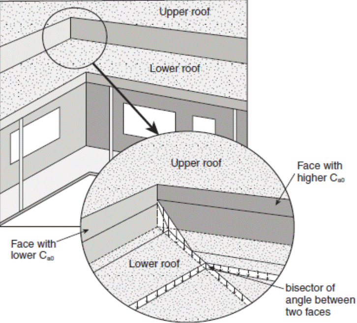
4.1.6.9. Gable Roofs
(1) For all gable roofs, the full and partial load cases defined in Article 4.1.6.3. shall be considered.
(2) For gable roofs with a slope of a > 15°, the unbalanced load case shall also be considered by setting the values of the accumulation factor, Ca, as follows:
(a) on the upwind side of the roof peak, Ca shall be taken as 0, and
(b) on the downwind side of the roof peak, Ca shall be taken as,
(i) 0.25 + a/20, where 15° ≤ a ≤ 20°, and
(ii) 1.25, where 20° < a ≤ 90°.
(3) For all gable roofs, the slope factor, Cs, shall be as prescribed in Sentences 4.1.6.2.(5) and (6).
(4) For all gable roofs, the wind exposure factor, Cw, shall be,
(a) as prescribed in Sentences 4.1.6.2.(3) and (4) for the full and partial load cases, and
(b) 1.0 for the unbalanced load case referred to in Sentence (2).
4.1.6.10. Arch Roofs, Curved Roofs and Domes
(1) For all arch roofs, curved roofs and domes, the full and partial load cases defined in Article 4.1.6.3. shall be considered.
(2) For arch roofs, curved roofs and domes with rise-to-span ratio h/b > 0.05 as shown in Figure 4.1.6.10.A., the load cases provided in Sentences (3) to (7) shall also be considered.
(3) For arch roofs with a slope at the edge αe ≤ 30° as shown in Figure 4.1.6.10.A. and as described in Table 4.1.6.10., Ca shall be,
(a) taken as 0 on the upwind side of the peak, and
(b) on the downwind side of the peak, taken as,
![]()
where,
x = horizontal distance from the roof peak,
h = height of arch, and
b = width of arch.
Figure 4.1.6.10.A.
Accumulation Factors for Arch Roofs and Curved Roofs(1)
Forming Part of Sentences 4.1.6.10.(2) to (4)
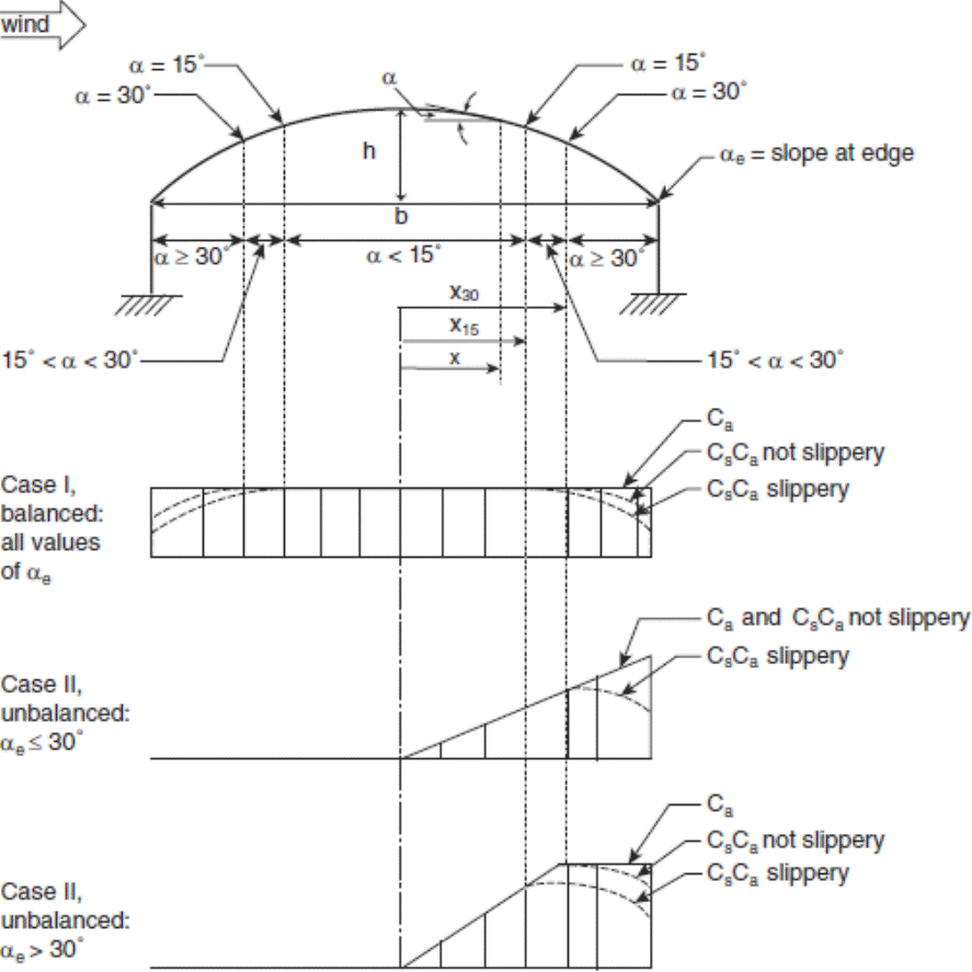
Notes to Figure 4.1.6.10.A.:
(1) Refer to Table 4.1.6.10. for applicable values of Cw and Sentences 4.1.6.2.(5) and (6) for applicable values of Cs.
Table 4.1.6.10.
Load Cases for Arch Roofs, Curved Roofs and Domes
Forming Part of Sentences 4.1.6.10.(3), (4) and (9)
| Item | Column 1 Load Case | Column 2 Range of application | Column 3 Factors - Arch Roofs, Curved Roofs and Domes Cw | Column 4 Factors - Arch and Curved Roofs Ca - Upwind Side | Column 5 Factors - Arch and Curved Roofs Ca - Downwind Side | Column 6 Factors - Domes Ca - Downwind Side |
| 1. | Case I | All values of h/b | As prescribed in Sentences 4.1.6.2.(3) and (4) | 1.0 | 1.0 | 1.0 |
| 2. | Case II | Slope at edge ≤ 30° h/b > 0.05 all values of x | 1.0 | 0.0 | Ca = (xh/0.03Cbb2) for h/b ≤ 0.12 Ca = (4x/Cbb) for h/b > 0.12 | Ca (x,y) = Ca(x,0)(1 – y/r) |
| 3. | Case II | Slope at edge > 30° h/b > 0.05 0 < x | 1.0 | 0.0 | Ca = (xh/0.06Cbx30b) for h/b ≤ 0.12 Ca = (2x/Cbx30) for h/b > 0.12 | Ca (x,y) = Ca(x,0)(1 – y/r) |
| 4. | Case II | Slope at edge > 30° h/b > 0.05 x30 ≤ x | 1.0 | 0.0 | Ca = (h/0.06Cbb) for h/b ≤ 0.12 Ca = (2/Cb) for h/b > 0.12 | Ca (x,y) = Ca(x,0)(1 – y/r) |
(4) For arch roofs with slope at the edge αe > 30° as shown in Figure 4.1.6.10.A. and as described in Table 4.1.6.10., Ca, shall be,
(a) taken as 0 on the upwind side of the peak, and
(b) on the downwind side of the peak,
(i) for the part of the roof between the peak and point where the slope α = 30°, taken as,
![]()
and
![]()
where,
x, h, b = as specified in Sentence (2), and
x30 = value of x where the slope α = 30°, and
(ii) for the part of the roof where the slope α >30°, taken as,
![]()
(5) Except as provided in Sentence (6), Ca for curved roofs shall be determined in accordance with the requirements for arch roofs stated in Sentences (3) and (4).
(6) Where the slope, α, of a curved roof at its peak is greater than 10°, Ca shall be determined in accordance with the requirements for gable roofs described in Article 4.1.6.9. using a slope equal to the mean slope of the curved roof.
(7) For domes of circular plan form as shown in Figure 4.1.6.10.B., Ca shall,
(a) along the central axis parallel to the wind, vary in the same way as for an arch roof with the same rise-to-span ratio, h/b, and
(b) off this axis, vary according to,
![]()
where,
Ca(x,y) = value of Ca at location (x,y),
Ca(x,0) = value of Ca on the central axis parallel to the wind,
x = distance along the central axis parallel to the wind,
y = horizontal coordinate normal to the x direction, and
r = radius of dome.
Figure 4.1.6.10.B.
Unbalanced Snow Accumulation Factor on a Circular Dome(1),(2)
Forming Part of Sentence 4.1.6.10.(7)
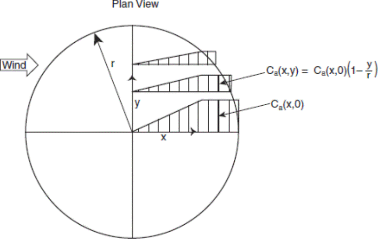
Notes to Figure 4.1.6.10.B.:
(1) Refer to Table 4.1.6.10. for applicable values of Cw and Sentences 4.1.6.2.(5) and (6) for applicable values of Cs.
(2) Refer to Sentences 4.1.6.10.(3) and (4) for the calculation of Ca(x,0).
(8) For all arch roofs, curved roofs and domes, the slope factor, Cs, shall be as prescribed in Sentences 4.1.6.2.(5) and (6).
(9) For all arch roofs, curved roofs and domes, the wind exposure factor, Cw, shall be as prescribed in Table 4.1.6.10.
4.1.6.11. Snow Loads Due to Sliding
(1) Except as provided in Sentence (2), where an upper roof, or part thereof, slopes downwards with a slope α > 0 towards a lower roof, the snow load, S, on the lower roof, determined in accordance with Articles 4.1.6.2. and 4.1.6.5., shall be augmented in accordance with Sentence (3) to account for the additional load resulting from sliding snow.
(2) Sentence (1) need not apply where,
(a) snow from the upper roof is prevented from sliding by a parapet or other effective means, or
(b) the upper roof is not considered slippery and has a slope less than 20°.
(3) The total weight of additional snow resulting from sliding shall be taken as half the total weight of snow resulting from the uniform load case prescribed in Article 4.1.6.2. with,
(a) the accumulation factor Ca = 1.0 for the relevant part of the upper roof,
(b) the slope factor, Cs, based on the slope of the lower roof, as prescribed in Sentences 4.1.6.2.(5) and (6), and
(c) the sliding snow distributed on the lower roof such that it is a maximum for x = 0 and decreases linearly to 0 at x = xd, as shown in Figure 4.1.6.11., where x and xd are as defined in Article 4.1.6.5.
Figure 4.1.6.11.
Snow Distribution on Lower Roof with Sloped Upper Roof
Forming Part of Sentence 4.1.6.11.(3)
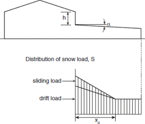
4.1.6.12. Valleys in Curved or Sloped Roofs
(1) For valleys in curved or sloped roofs with a slope α >10°, in addition to the full and partial load cases defined in Article 4.1.6.3., the non-uniform load Cases II and III described in Sentences (2) and (3) shall be considered to account for sliding, creeping and movement of meltwater.
(2) For Case II as shown in Figure 4.1.6.12., the accumulation factor, Ca, shall be calculated as follows:
![]()
x = horizontal distance from the bottom of the valley, and
b = twice the horizontal distance between the bottom of the valley and the peak of the roof surface under consideration.
(3) For Case III as shown in Figure 4.1.6.12., Ca shall be calculated as follows:
![]()
where,
x, b = as specified in Sentence (2).
Figure 4.1.6.12.
Snow Loads in Valleys of Sloped or Curved Roofs(1),(2)
Forming Part of Sentences 4.1.6.12.(2) and (3)
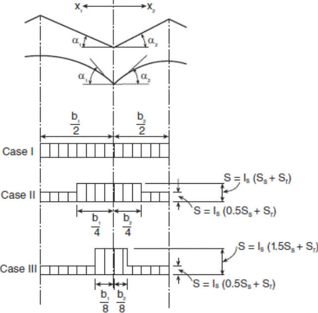
Notes to Figure 4.1.6.12.:
(1) Cw = 1.0, as specified in Sentence 4.1.6.2.(3).
(2) Cs = 1.0, as specified in Sentence 4.1.6.2.(7).
4.1.6.13. Specific Weight of Snow
(1) For the purposes of calculating snow loads in drifts, the specific weight of snow, γ, shall be taken as the lesser of 4.0 kN/m3 and 0.43SS + 2.2 kN/m3.
4.1.6.14. Snow Removal
(1) Snow removal by mechanical, thermal, manual or other means shall not be used as a rationale to reduce design snow loads.
4.1.6.15. Ice Loading of Structures
(1) For lattice structures connected to the building, and other building components or appurtenances involving small width elements subject to significant ice accretion, the weight of ice accretion and the effective area presented to wind shall be as prescribed in CSA S37, “Antennas, Towers, and Antenna-Supporting Structures”.
4.1.7. Wind Load
4.1.7.1. Specified Wind Load
(1) The specified wind loads for a building and its components shall be determined using the Static, Dynamic or Wind Tunnel Procedure as provided in Sentences (2) to (5).
(2) For the design of buildings that are not classified as dynamically sensitive in accordance with Sentence 4.1.7.2.(1), one of the following procedures shall be used to determine the specified wind loads:
(a) the Static Procedure described in Article 4.1.7.3.,
(b) the Dynamic Procedure described in Article 4.1.7.8., or
(c) the Wind Tunnel Procedure described in Article 4.1.7.12.
(3) For the design of buildings that are classified as dynamically sensitive in accordance with Sentence 4.1.7.2.(2), one of the following procedures shall be used to determine the specified wind loads:
(a) the Dynamic Procedure described in Article 4.1.7.8., or
(b) the Wind Tunnel Procedure described in Article 4.1.7.12.
(4) For the design of buildings that may be subject to wake buffeting or channelling effects from nearby buildings, or that are classified as very dynamically sensitive in accordance with Sentence 4.1.7.2.(3), the Wind Tunnel Procedure described in Article 4.1.7.12. shall be used to determine the specified wind loads.
(5) For the design of cladding and secondary structural members, one of the following procedures shall be used to determine the specified wind loads:
(a) the Static Procedure described in Article 4.1.7.3., or
(b) the Wind Tunnel Procedure described in Article 4.1.7.12.
(6) Computational fluid dynamics shall not be used to determine the specified wind loads for a building and its components.
4.1.7.2. Classification of Buildings
(1) Except as provided in Sentences (2) and (3), a building is permitted to be classified as not dynamically sensitive.
(2) A building shall be classified as dynamically sensitive if,
(a) its lowest natural frequency is less than 1 Hz and greater than 0.25 Hz,
(b) its height is greater than 60 m, or
(c) its height is greater than 4 times its minimum effective width considering all wind directions, where the effective width, w, of a building shall be taken as,
![]()
where,
the summations are over the height of the building for a given wind direction,
hi = the height above grade to level i, and
wi = the width normal to the wind direction at height hi.
(3) A building shall be classified as very dynamically sensitive if,
(a) its lowest natural frequency is less than or equal to 0.25 Hz, or
(b) its height is more than 6 times its minimum effective width, where the minimum effective width is determined in accordance with Clause (2)(c).
4.1.7.3. Static Procedure
(1) The specified external pressure or suction due to wind on part or all of a surface of a building shall be calculated using the following formula:
p = IwqCeCtCgCp
where,
p = specified external pressure acting statically and in a direction normal to the surface, considered positive when the pressure acts towards the surface and negative when it acts away from the surface,
Iw = importance factor for wind load, as provided in Table 4.1.7.3.,
q = reference velocity pressure, as provided in Sentence (4),
Ce = exposure factor, as provided in Sentences (5) and (7),
Ct = topographic factor, as provided in Article 4.1.7.4.,
Cg = gust effect factor, as provided in Sentence (8), and
Cp = external pressure coefficient, as provided in Articles 4.1.7.5. and 4.1.7.6.
Table 4.1.7.3.
Importance Factor for Wind Load, IW
Forming Part of Sentence 4.1.7.3.(1)
| Item | Column 1 Importance Category | Column 2 Importance Factor, IW ULS | Column 3 Importance Factor, IW SLS |
| 1. | Low | 0.8 | 0.75 |
| 2. | Normal | 1.0 | 0.75 |
| 3. | High | 1.15 | 0.75 |
| 4. | Post-disaster | 1.25 | 0.75 |
(2) The net wind load for the building as a whole shall be the algebraic difference of the loads on the windward and the leeward surfaces, and in some cases may be calculated as the sum of the products of the external pressures or suctions and the areas of the surfaces over which they are averaged as provided in Sentence (1).
(3) The net specified pressure due to wind on part or all of a surface of a building shall be the algebraic difference, such as to produce the most critical effect, of the external pressure or suction calculated in accordance with Sentence (1) and the specified internal pressure or suction due to wind calculated as follows:
pi = IwqCeiCtCgiCpi
where,
pi = specified internal pressure acting statically and in a direction normal to the surface, either as a pressure directed toward the surface or as a suction directed away from the surface,
Iw = importance factor for wind load, as defined in Sentence (1)
q = reference velocity pressure, as defined in Sentence (1)
Cei = exposure factor for internal pressure, as provided in Sentence (7),
Ct = topographic factor, as defined in Sentence (1),
Cgi = internal gust effect factor, as provided in Sentence (10), and
Cpi = internal pressure coefficient, as provided in Article 4.1.7.7.
(4) The reference velocity pressure, q, shall be the appropriate value determined in conformance with Subsection 1.1.2. based on a probability of being exceeded in any one year of 1-in-50.
(5) The exposure factor Ce, shall be based on the reference height, h, determined in accordance with Sentence (6) for the surface or part of the surface under consideration and shall be,
(a) (h/10)0.2 but not less than 0.9 for open terrain, where open terrain is level terrain with only scattered buildings, trees or other obstructions, open water or shorelines thereof,
(b) 0.7(h/12)0.3 but not less than 0.7 for rough terrain, where rough terrain is suburban, urban or wooded terrain extending upwind from the building uninterrupted for at least 1 km or 20 times the height of the building, whichever is greater, or
(c) an intermediate value between the two exposures defined in Clauses (a) and (b) in cases where the site is less than 1 km or 20 times the height of the building from a change in terrain conditions, whichever is greater, provided an appropriate interpolation method is used.
(6) The reference height, h, shall be determined as follows:
(a) for buildings with height less than or equal to 20 m and less than the smaller plan dimension, h shall be the mid-height of the roof above grade, but shall not be less than 6 m,
(b) for other buildings, h shall be,
(i) the actual height above grade of the point on the windward wall for which external pressures are being calculated,
(ii) the mid-height of the roof for pressures on surfaces parallel to the wind direction, and
(iii) the mid-height of the building for pressures on the leeward wall, and
(c) for any structural element exposed to wind, h shall be the mid-height of the element above the ground.
(7) The exposure factor for internal pressure, Cei, shall be determined as follows:
(a) for buildings whose height is greater than 20 m and that have a dominant opening, Cei shall be equal to the exposure factor for external pressures, Ce, calculated at the mid-height of the dominant opening, and
(b) for other buildings, Cei shall be the same as the exposure factor for external pressures, Ce, calculated for a reference height, h, equal to the mid-height of the building or 6 m, whichever is greater.
(8) Except as provided in Sentences (9) and 4.1.7.6.(1), the gust effect factor, Cg, shall be one of the following values:
(a) 2.0 for the building as a whole and main structural members, or
(b) 2.5 for external pressures and suctions on secondary structural members including cladding.
(9) For cases where Cg and Cp are combined into a single product, CpCg, as provided in Article 4.1.7.6., the values Cp and Cg need not be independently specified.
(10) The internal gust effect factor, Cgi, shall be 2.0, except it is permitted to be calculated using the following equation for large structures enclosing a single large unpartitioned volume that does not have numerous overhead doors or openings:

where,
V0 = internal volume in m3, and
A = total area of all exterior openings of the volume in m2.
4.1.7.4. Topographic Factor
(1) Except as provided in Sentence (2), the topographic factor, Ct, shall be taken as 1.0.
(2) For buildings on hills or escarpments with slope, Hh/(2Lh), greater than 0.1 as shown in Figure 4.1.7.4., the topographic factor, Ct, shall be calculated as follows:
![]()
where,
![]()
where,
ΔSmax = applicable values from Table 4.1.7.4.,
x = horizontal distance from the peak of the hill or escarpment,
Lh = horizontal distance upwind from the peak to the point where the ground surface lies at half the height of the hill or escarpment, or 2Hh where Hh is the height of the hill or escarpment, whichever is greater,
z = height above ground, and
k and α = applicable constants from Table 4.1.7.4. based on shape of hill or escarpment.
Figure 4.1.7.4.
Speed-up of Mean Velocity on a Hill or Escarpment(1)
Forming Part of Sentence 4.1.7.4.(2)
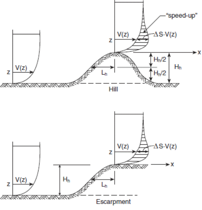
Notes to Figure 4.1.7.4.:
(1) V(z) = wind speed.
Table 4.1.7.4.
Parameters for Maximum Speed-up Over Hills and Escarpments
Forming Part of Sentence 4.1.7.4.(2)
| Item | Column 1 Shape of Hill or Escarpment | Column 2 ΔSmax(1) | Column 3 α | Column 4 k, where x < 0 | Column 5 k, where x ≥ 0 |
| 1. | 2-dimensional hill | 2.2 Hh/Lh | 3 | 1.5 | 1.5 |
| 2. | 2-dimensional escarpment | 1.3 Hh/Lh | 2.5 | 1.5 | 4 |
| 3. | 3-dimensional axi-symmetrical hill | 1.6 Hh/Lh | 4 | 1.5 | 1.5 |
Notes to Table 4.1.7.4.:
(1) For Hh/Lh > 0.5, assume Hh/Lh = 0.5 and substitute 2 Hh for Lh in the equation for ΔS.
4.1.7.5. External Pressure Coefficients
(1) Applicable values of external pressure coefficients, Cp, are provided in,
(a) Sentences (2) to (5), and
(b) Article 4.1.7.6. for certain shapes of low buildings.
(2) For the design of the main structural system, the value of Cp shall be established as follows, where H is the height of the building and D is the width of the building parallel to the wind direction:
(a) on the windward face,
Cp = 0.6 for H/D < 0.25
= 0.27(H/D + 2) for 0.25 ≤ H/D < 1.0
= 0.8 for H/D ≥ 1.0,
(b) on the leeward face,
Cp = –0.3 for H/D < 0.25
= –0.27(H/D + 0.88) for 0.25 ≤ H/D < 1.0
= –0.5 for H/D ≥ 1.0, and
(c) on the walls parallel to the wind, Cp = –0.7.
(3) For the design of roofs, the value of Cp shall be established as follows, where x is the distance from the upwind edge of the roof:
(a) for H/D ≥ 1.0, Cp = –1.0, and
(b) for H/D <1.0,
Cp = –1.0 for x ≤ H
= –0.5 for x > H
(4) For the design of the cladding and of secondary structural elements supporting the cladding, the value of Cp shall be established as follows, where W and D are the widths of the building:
(a) on walls, Cp shall be taken as ±0.9, except that within a distance equal to the larger of 0.1D and 0.1W from a building corner the negative value of Cp shall be taken as –1.2,
(b) on walls where vertical ribs deeper than 1 m are placed on the facade, Cp shall be taken as ±0.9, except that within a distance equal to the larger of 0.2D and 0.2W from a building corner the negative value of Cp shall be taken as –1.4, and
(c) on roofs, Cp shall be taken as –1.0, except that,
(i) within a distance equal to the larger of 0.1D and 0.1W from a roof edge, Cp shall be taken as –1.5,
(ii) in a zone that is within a distance equal to the larger of 0.2D and 0.2W from a roof corner, Cp shall be taken as –2.3 but is permitted to be taken as –2.0 for roofs with perimeter parapets that are higher than 1 m, and
(iii) on lower levels of flat stepped roofs, positive pressure coefficients established for the walls of the steps apply for a distance b as shown in Figure 4.1.7.6.D.
(5) For the design of balcony guards, the internal pressure coefficient, Cpi, shall be taken as zero and the value of Cp shall be taken as ±0.9, except that within a distance equal to the larger of 0.1D and 0.1W from a building corner, Cp shall be taken as ±1.2.
4.1.7.6. External Pressure Coefficients for Low Buildings
(1) For the design of buildings with a height, H, that is less than or equal to 20 m and less than the smaller plan dimension, the values of the product of the pressure coefficient and gust factor, CpCg, provided in Sentences (2) to (9) are permitted to be used.
(2) For the design of the main structural system of the building, which is affected by wind pressures on more than one surface, the values of CpCg are provided in Figure 4.1.7.6.A.
(3) For the design of individual walls and wall cladding, the values of CpCg are provided in Figure 4.1.7.6.B.
(4) For the design of roofs with a slope less than or equal to 7o, the values of CpCg are provided in Figure 4.1.7.6.C.
(5) For the design of flat roofs with steps in elevation, the values of CpCg are provided in Figure 4.1.7.6.D.
(6) For the design of gabled or hipped, single-ridge roofs with slope greater than 7o, the values of CpCg are provided in Figure 4.1.7.6.E.
(7) For the design of gabled, multi-ridge roofs, the values of CpCg are provided in,
(a) Figure 4.1.7.6.C. for roofs with slope less than or equal to 10o, and
(b) Figure 4.1.7.6.F. for roofs with slope greater than 10o.
(8) For monosloped roofs, the values of CpCg are provided in,
(a) Figure 4.1.7.6.C. for roofs with a slope less than or equal to 3o, and
(b) Figure 4.1.7.6.G. for roofs with a slope greater than 3o and less than or equal to 30o.
(9) For sawtooth roofs, the values of CpCg are provided in,
(a) Figure 4.1.7.6.C. for roofs with a slope less than or equal to 10o, and
(b) Figure 4.1.7.6.H. for roofs with a slope greater than 10o.
Figure 4.1.7.6.A.
External Peak Values of CpCg for Primary Structural Actions Arising from Wind Load Acting Simultaneously on All Surfaces of Low Buildings, H ≤20 m(1),(2),(3),(4)
Forming Part of Sentence 4.1.7.6.(2)
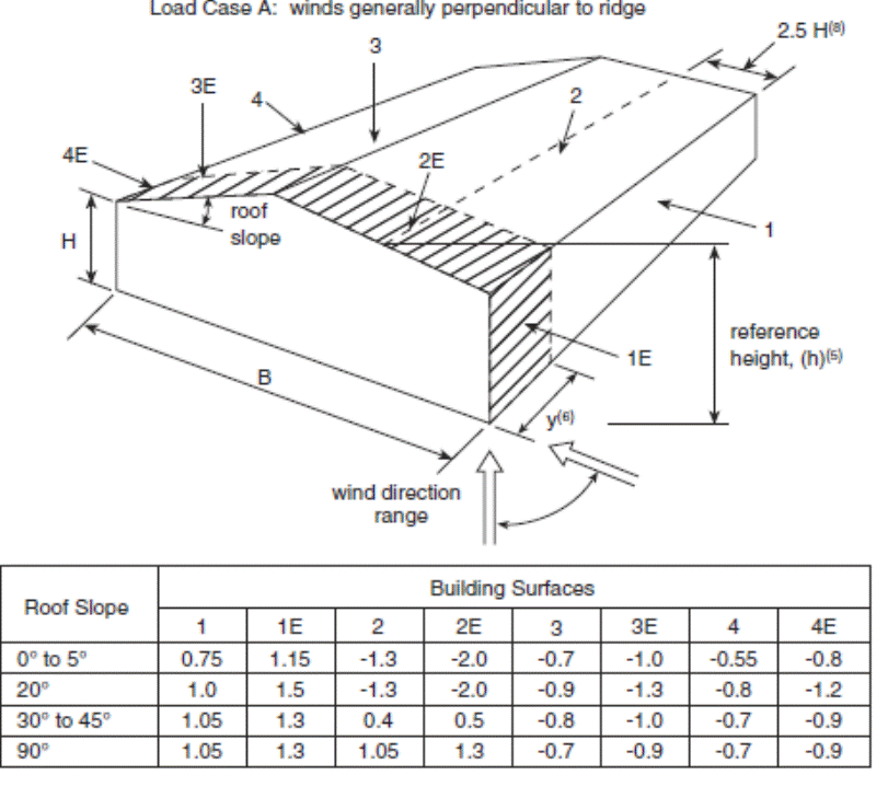
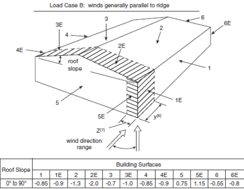
Notes to Figure 4.1.7.6.A.:
(1) The building shall be designed for all wind directions. Each corner shall be considered in turn as the windward corner shown in the Figure. For all roof slopes, Load Case A and Load Case B are required as two separate loading conditions to generate the wind actions, including torsion, to be resisted by the structural system.
(2) For values of roof slope not shown, the coefficient, CpCg, may be interpolated linearly.
(3) Positive coefficients denote forces toward the surface, whereas negative coefficients denote forces away from the surface.
(4) For the design of foundations, exclusive of anchorages to the frame, only 70% of the effective load is to be considered.
(5) The reference height, h, for pressures is the mid-height of the roof or 6 m, whichever is greater. The eave height, H, may be substituted for the mid-height of the roof if the roof slope is less than 7o.
(6) End-zone width, y, is the greater of 6 m or 2z, where z is the width of the gable-wall end zone defined for Load Case B. Alternatively, for buildings with frames, y may be the distance between the end and the first interior frame.
(7) End-zone width, z, is the lesser of 10% of the least horizontal dimension and 40% of height, H, but not less than 4% of the least horizontal dimension or 1 m.
(8) For B/H > 5 in Load Case A, the listed negative coefficients on surfaces 2 and 2E shall only be applied on an area whose width is 2.5H measured from the windward eave. The pressures on the remainder of the windward roof may be reduced to the pressures for the leeward roof.
Figure 4.1.7.6.B.
External Peak Values of CpCg on Individual Walls for the Design of Cladding and Secondary Structural Members(1),(2),(3),(4),(5)
Forming Part of Sentence 4.1.7.6.(3)
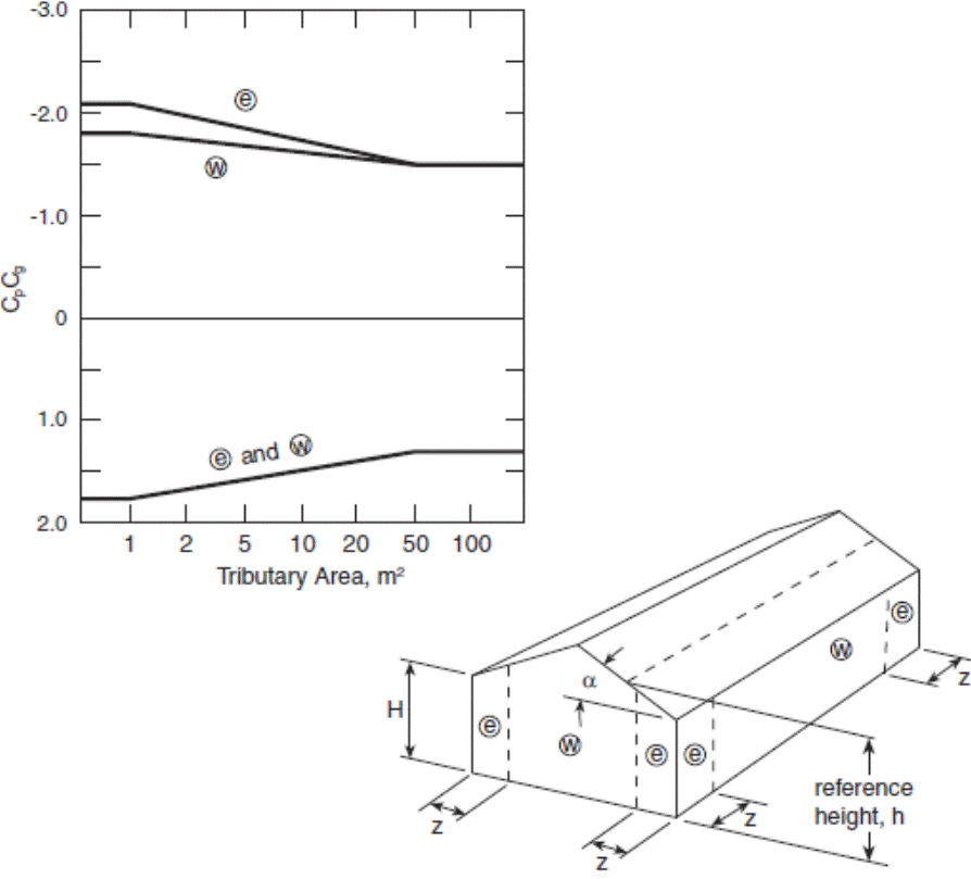
Notes to Figure 4.1.7.6.B.:
(1) These coefficients apply for any roof slope, α.
(2) End-zone width, z, is the lesser of 10% of the least horizontal dimension and 40% of height, H, but not less than 4% of the least horizontal dimension or 1 m.
(3) Combinations of exterior and interior pressures shall be evaluated to obtain the most severe loading.
(4) Positive coefficients denote forces toward the surface, whereas negative coefficients denote forces away from the surface. Each structural element shall be designed to withstand forces of both signs.
(5) Pressure coefficients generally apply for facades with architectural features; however, where vertical ribs deeper than 1 m are placed on a facade, a local CpCg of –2.8 applies to zone e.
Figure 4.1.7.6.C.
External Peak Values of CpCg on Roofs with a Slope of 7o or Less for the Design of Structural Components and Cladding(3),(4),(5)
Forming Part of Sentences 4.1.7.6.(4), (7), (8), and (9)
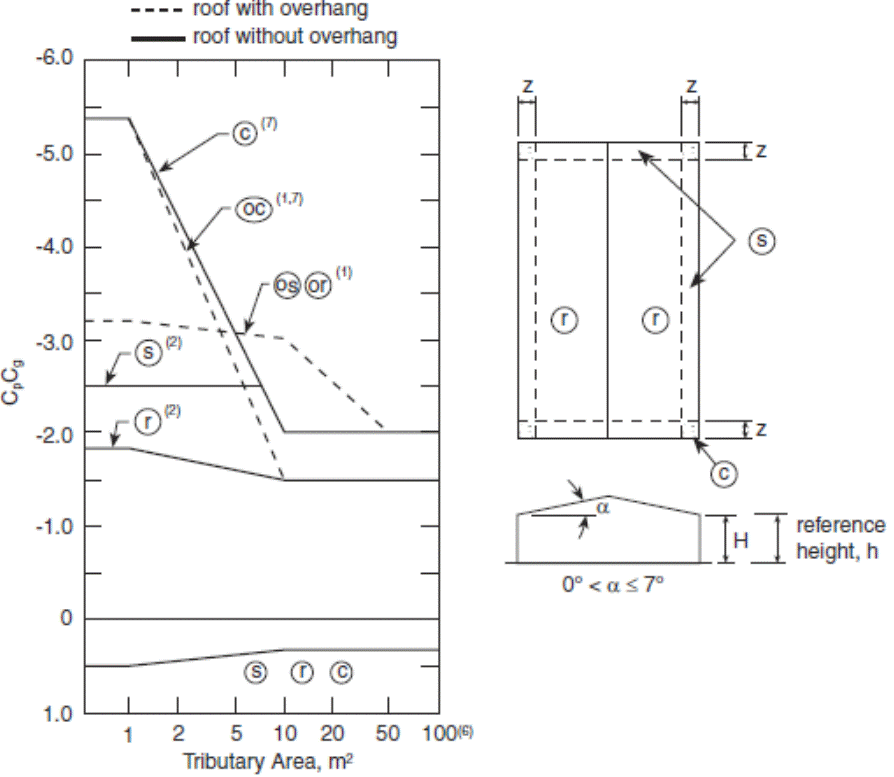
Notes to Figure 4.1.7.6.C.:
(1) Coefficients for overhung roofs have the prefix “o” and refer to the same roof areas as referred to by the corresponding symbol without a prefix. They include contributions from both upper and lower surfaces. In the case of overhangs, the walls are inboard of the roof outline.
(2) s and r apply to both roofs and upper surfaces of canopies.
(3) End-zone width, z, is the lesser of 10% of the least horizontal dimension and 40% of height, H, but not less than 4% of the least horizontal dimension or 1 m.
(4) Combinations of exterior and interior pressures shall be evaluated to obtain the most severe loading.
(5) Positive coefficients denote forces toward the surface, whereas negative coefficients denote forces away from the surface. Each structural element shall be designed to withstand forces of both signs.
(6) For calculating the uplift forces on tributary areas larger than 100 m2 on unobstructed nearly-flat roofs with low parapets, and where the centre of the tributary area is at least twice the height of the building from the nearest edge, the value of CpCg may be reduced from –1.5 to –1.1 at x/H = 2 and further reduced linearly to –0.6 at x/H = 5, where x is the distance to the nearest edge and H is the height of the building.
(7) For roofs having a perimeter parapet with a height of 1 m or greater, the corner coefficients CpCg for tributary areas less than 1 m2 can be reduced from –5.4 to –4.4.
Figure 4.1.7.6.D.
External Peak Values of CpCg for the Design of the Structural Components and Cladding of Buildings with Stepped Roofs(1),(2)
Forming Part of Sentences 4.1.7.5.(4) and 4.1.7.6.(5)
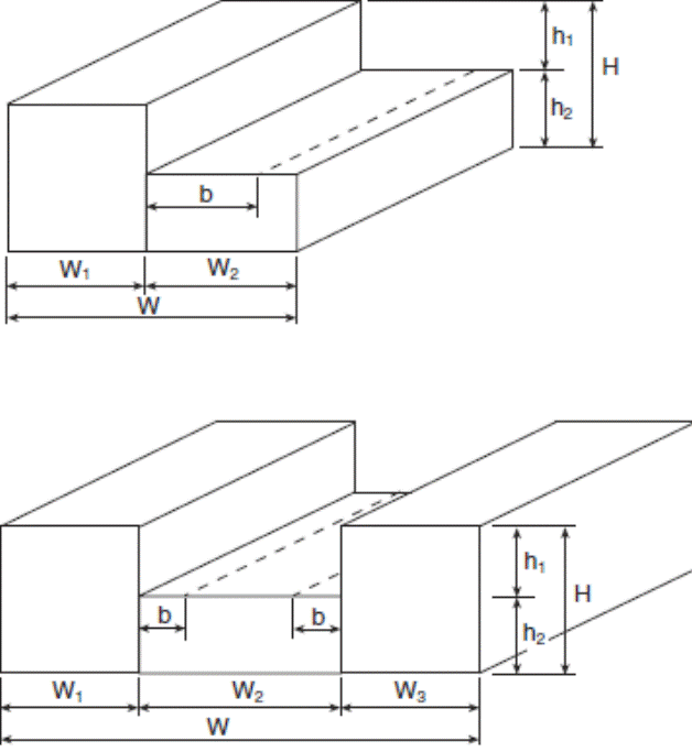
Notes to Figure 4.1.7.6.D.:
(1) The zone designations, pressure-gust coefficients and Notes to Figure 4.1.7.6.C. apply on both the upper and lower levels of flat stepped roofs, except that on the lower levels, positive pressure-gust coefficients equal to those in Figure 4.1.7.6.B. for walls apply for a distance, b, where b is equal to 1.5h1 but not greater than 30 m. For all walls in Figure 4.1.7.6.D., zone designations and pressure coefficients provided for walls in Figure 4.1.7.6.B. apply.
(2) Note (1) applies only when the following conditions are met: h1 ≥ 0.3H, h1 ≥ 3 m, and W1, W2, or W3 is greater than 0.25W but not greater than 0.75W.
Figure 4.1.7.6.E.
External Peak Values of CpCg on Single-Span Gabled and Hipped Roofs with a Slope Greater than 7o for the Design of Structural Components and Cladding(1),(2),(3),(4),(5)
Forming Part of Sentence 4.1.7.6.(6)
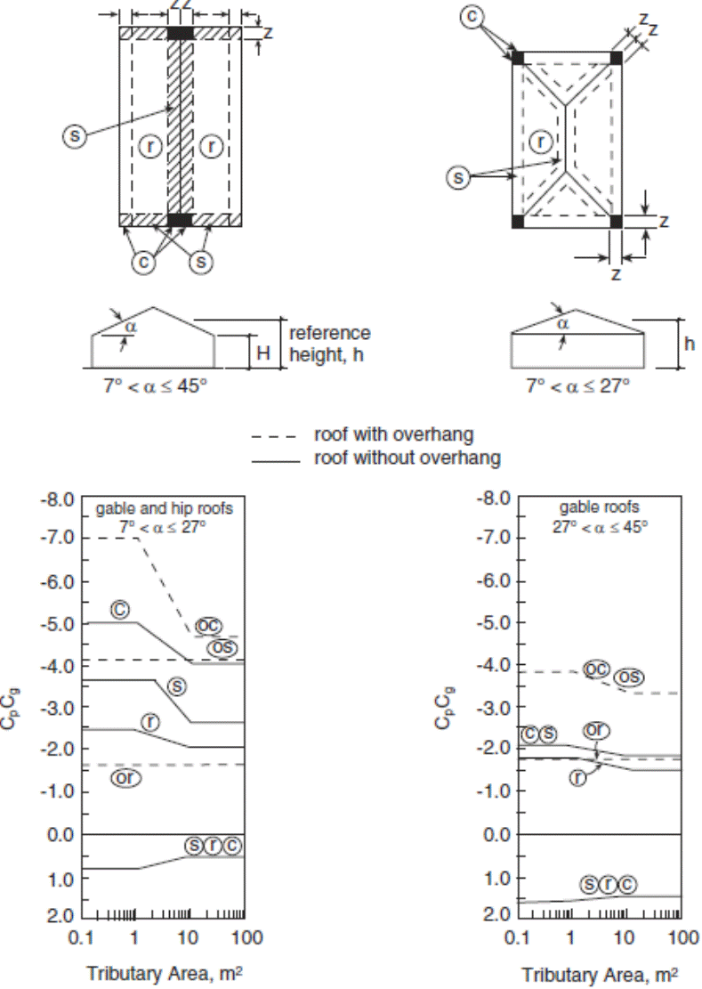
Notes to Figure 4.1.7.6.E.:
(1) Coefficients for overhung roofs have the prefix “o” and refer to the same roof areas as referred to by the corresponding symbol without a prefix. They include contributions from both upper and lower surfaces.
(2) End-zone width, z, is the lesser of 10% of the least horizontal dimension and 40% of height, H, but not less than 4% of the least horizontal dimension or 1 m.
(3) Combinations of external and internal pressures shall be evaluated to obtain the most severe loading.
(4) Positive coefficients denote forces toward the surface, whereas negative coefficients denote forces away from the surface. Each structural element shall be designed to withstand forces of both signs.
(5) For hipped roofs with 7° < α ≤ 27°, edge/ridge strips and pressure-gust coefficients for ridges of gabled roofs apply along each hip.
Figure 4.1.7.6.F.
External Peak Values of CpCg on Multi-Span Gabled (Folded) Roofs with a Slope Greater than 10o for the Design of Structural Components and Cladding(1),(2),(3),(4)
Forming Part of Sentence 4.1.7.6.(7)
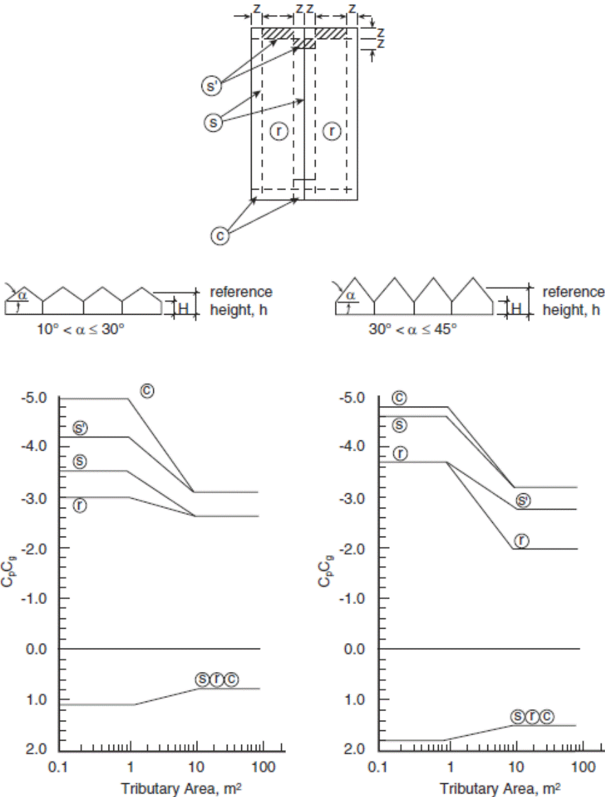
Notes to Figure 4.1.7.6.F.:
(1) End-zone width, z, is the lesser of 10% of the least horizontal dimension and 40% of height, H, but not less than 4% of the least horizontal dimension or 1 m.
(2) Combinations of external and internal pressures shall be evaluated to obtain the most severe loading.
(3) Positive coefficients denote forces toward the surface, whereas negative coefficients denote forces away from the surface. Each structural element shall be designed to withstand forces of both signs.
(4) Where α ≤ 10°, the coefficients given in Figure 4.1.7.6.C. apply. Where α > 7°, use α = 7°.
Figure 4.1.7.6.G.
External Peak Values of CpCg on Monoslope Roofs for the Design of Structural Components and Cladding(1),(2),(3),(4)
Forming Part of Sentence 4.1.7.6.(8)
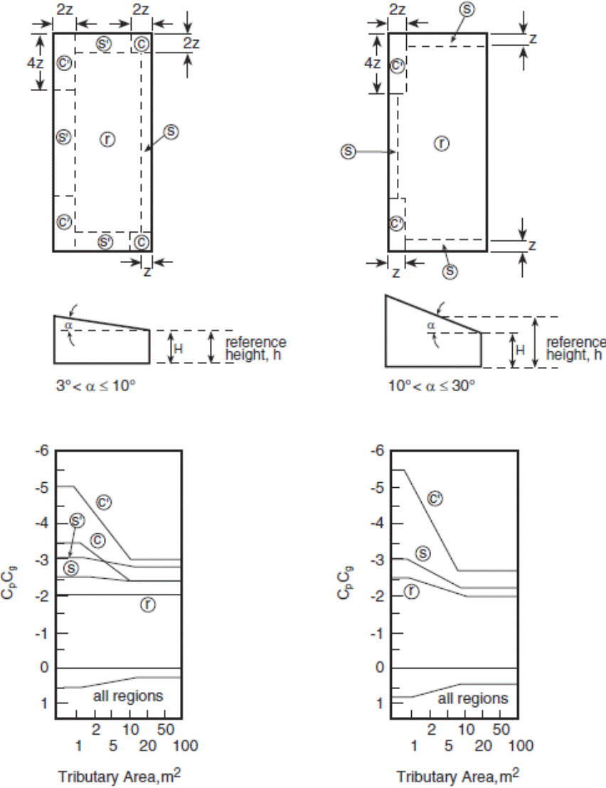
Notes to Figure 4.1.7.6.G.:
(1) End-zone width, z, is the lesser of 10% of the least horizontal dimension and 40% of height, H, but not less than 4% of the least horizontal dimension or 1 m.
(2) Combinations of external and internal pressures shall be evaluated to obtain the most severe loading.
(3) Positive coefficients denote forces toward the surface, whereas negative coefficients denote forces away from the surface. Each structural element shall be designed to withstand forces of both signs.
(4) Where α ≤ 3°, the coefficients given in Figure 4.1.7.6.C. apply.
Figure 4.1.7.6.H.
External Peak Values of CpCg on Sawtooth Roofs with a Slope Greater than 10˚ for the Design of Structural Components and Cladding(1),(2),(3),(4),(5)
Forming Part of Sentence 4.1.7.6.(9)
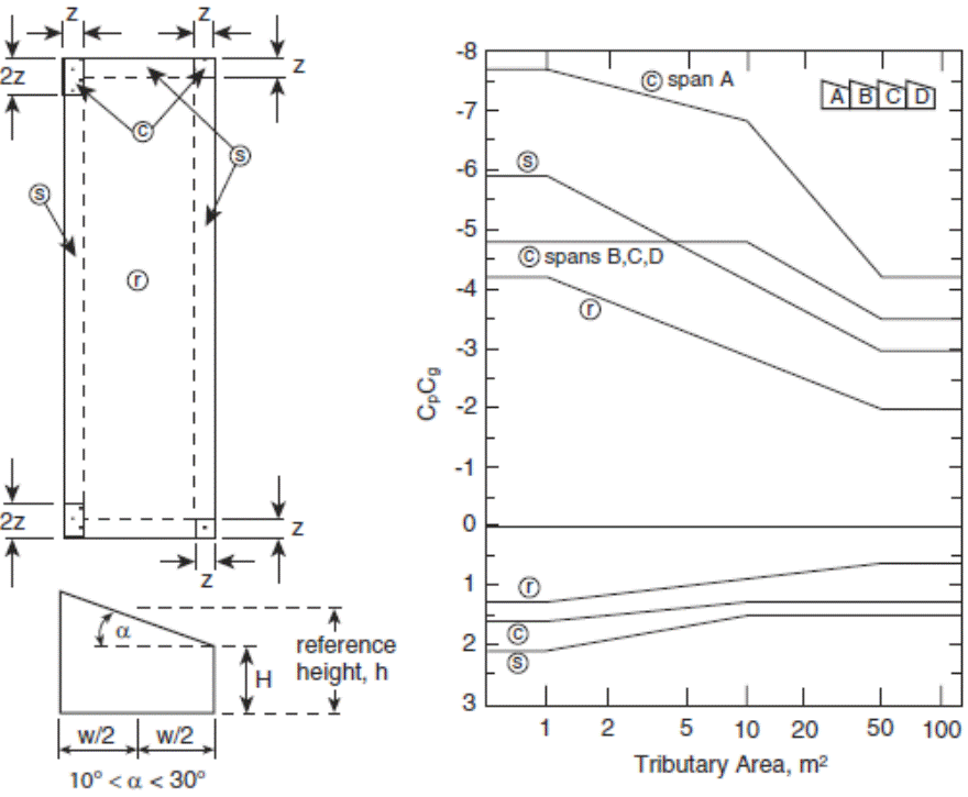
Notes to Figure 4.1.7.6.H.:
(1) End-zone width, z, is the lesser of 10% of the least horizontal dimension and 40% of height, H, but not less than 4% of the least horizontal dimension or 1 m.
(2) Combinations of external and internal pressures shall be evaluated to obtain the most severe loading.
(3) Positive coefficients denote forces toward the surface, whereas negative coefficients denote forces away from the surface. Each structural element shall be designed to withstand forces of both signs.
(4) Negative coefficients on corner zones of Span A differ from those on Spans B, C, and D.
(5) Where α ≤ 10°, the coefficients given in Figure 4.1.7.6.C. apply. Where α > 7°, use α = 7°.
4.1.7.7. Internal Pressure Coefficient
(1) The internal pressure coefficient, Cpi, shall be as prescribed in Table 4.1.7.7.
Table 4.1.7.7.
Internal Pressure Coefficients
Forming Part of Sentence 4.1.7.7.(1)
| Item | Column 1 Building openings | Column 2 Values for Cpi |
| 1. | Uniformly distributed small openings amounting to less than 0.1% of the total surface area | –0.15 to 0.0 |
| 2. | Non-uniformly distributed openings of which none is significant or significant openings that are wind-resistant and closed during storms | –0.45 to +0.30 |
| 3. | Large openings likely to remain open during storms | –0.70 to +0.70 |
4.1.7.8. Dynamic Procedure
(1) For the application of the Dynamic Procedure, the provisions of Article 4.1.7.3. shall be followed, except that the exposure factor, Ce, shall be as prescribed in Sentences (2) and (3), and the gust effect factor, Cg, shall be as prescribed in Sentence (4), when determining the wind loads on the main structural system.
(2) For buildings in open terrain as described in Clause 4.1.7.3.(5)(a), the value of Ce for the design of the main structural system shall be calculated as follows:
Ce = (h/10)0.28, but 1.0 ≤ Ce ≤ 2.5
(3) For buildings in rough terrain as described in Clause 4.1.7.3.(5)(b), the value of Ce for the design of the main structural system shall be calculated as follows:
Ce = 0.5(h/12.7)0.5, but 0.5 ≤ Ce ≤ 2.5
(4) For the design of the main structural system, Cg shall be calculated as follows:
Cg = 1 + gp(δ/μ)
where,
gp = peak factor calculated as![]() , and
, and
 ,
,
where,
υ = average fluctuation rate calculated as  ,
,
T = 3 600 s,
K = 0.08 for open terrain and 0.10 for rough terrain,
CeH = exposure factor evaluated at reference height h = H,
B = background turbulence factor, a function of w/H determined from Figure 4.1.7.8.,
s = size reduction factor calculated as ![Image of formula: (pi/3)[1/(1+(8(fsubscript n)H)/3(Vsubscript H))][1/(1+(10(fsubscript n)w)/Vsubscript H)].](/laws/images/en/120332_e_files/image051.gif) ,
,
F = gust energy ratio calculated as ![]() , where x0 = (1 220 fn/VH), and
, where x0 = (1 220 fn/VH), and
β = damping ratio, which shall be determined by a rational method or may be taken to be 0.01 for steel structures, 0.02 for concrete structures and 0.015 for composite structures,
where,
fnD = natural frequency of vibration of the building in the along-wind direction, in Hz,
fn = lowest natural frequency of the building, in Hz, as described in Sentences 4.1.7.2.(2) and (3),
H = height of the building,
w = effective width of windward face of the building calculated as ![]() , where wi = width normal to wind direction at height hi, and
, where wi = width normal to wind direction at height hi, and
VH = mean wind speed at the top of the structure, in m/s, calculated as ![]() ,
,
where,
![]() = reference wind speed at a height of 10 m, in m/s, calculated as
= reference wind speed at a height of 10 m, in m/s, calculated as ![]() ,
,
where,
Iw = importance factor,
q = reference velocity pressure, in Pa, and
ϱ = air density = 1.2929 kg/m3.
Figure 4.1.7.8.
Background Turbulence Factor, B
Forming Part of Sentence 4.1.7.8.(4)
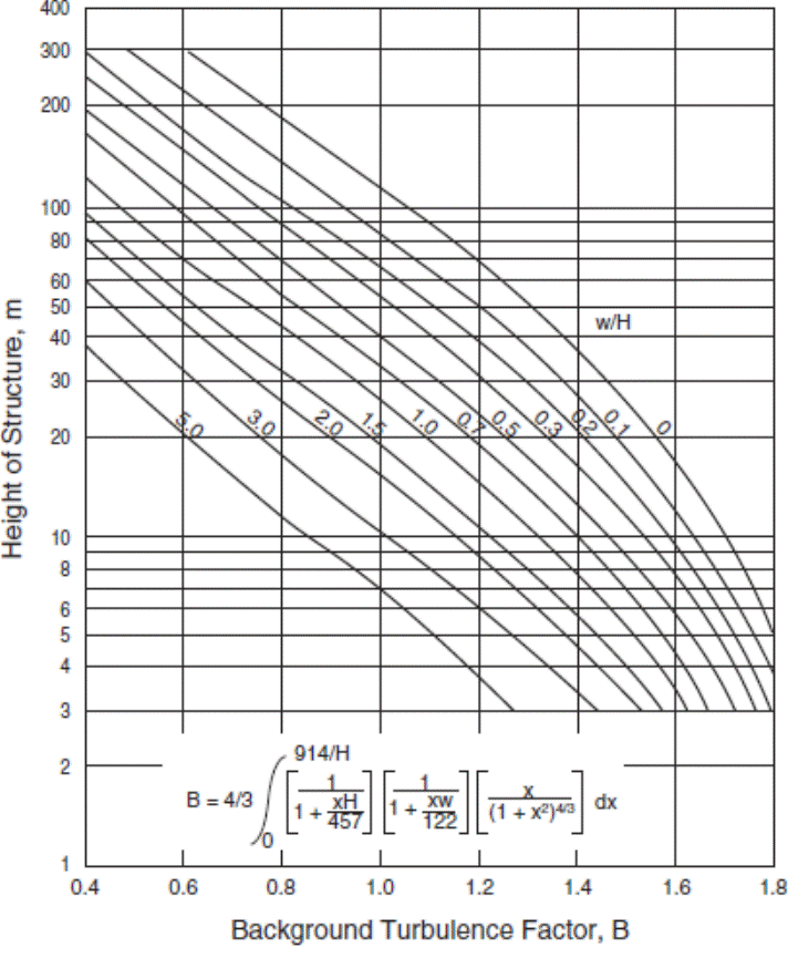
4.1.7.9. Full and Partial Wind Loading
(1) Except where the wind loads are derived from the combined CpCg values determined in accordance with Article 4.1.7.6., buildings and structural members shall be capable of withstanding the effects of,
(a) the full wind loads acting along each of the two principal horizontal axes considered separately,
(b) the wind loads as described in Clause (a) but with 100% of the load removed from any one portion of the area,
(c) the wind loads as described in Clause (a) but with both axes considered simultaneously at 75% of their full value, and
(d) the wind loads as described in Clause (c) but with 50% of these loads removed from any portion of the area.
4.1.7.10. Interior Walls and Partitions
(1) In the design of interior walls and partitions, due consideration shall be given to differences in air pressure on opposite sides of the wall or partition that may result from,
(a) pressure differences between the windward and leeward sides of a building,
(b) stack effects due to a difference in air temperature between the exterior and interior of the building, and
(c) air pressurization by the mechanical services of the building.
4.1.7.11. Exterior Ornamentations, Equipment and Appendages
(1) The effects of wind loads on exterior ornamentations, equipment and appendages, including the increase in exposed area as a result of ice buildup as described in CSA S37, “Antennas, Towers, and Antenna-Supporting Structures”, shall be considered in the structural design of the connections and the building.
(2) Where there are a number of similar components, the net increase in force is permitted to be based on the total area for all similar components as opposed to the summation of forces of individual elements.
4.1.7.12. Wind Tunnel Procedure
(1) Except as provided in Sentences (2) and (3), wind tunnel tests on scale models to determine wind loads on buildings shall be conducted in accordance with ASCE/SEI 49, “Wind Tunnel Testing for Buildings and Other Structures”.
(2) Where an adjacent building provides substantial sheltering effect, the wind loads for the main structural system shall be no lower than 80% of the loads determined from tests described in Sentence (1) with the effect of the sheltering building removed as applied to,
(a) the base shear force for buildings with ratio of height to minimum effective width, as described in Sentence 4.1.7.2.(2), less than or equal to 1.0, or
(b) the base moment for buildings with a ratio of height to minimum effective width greater than 1.0.
(3) For the design of cladding and secondary structural members, the exterior wind loads determined from the wind tunnel tests shall be no less onerous than those determined by analysis in accordance with Article 4.1.7.3. using the following assumptions:
(a) Cp = ±0.72 and Cg = 2.5, where the height of the building is greater than 20 m or greater than its minimum effective width, and
(b) CpCg = 80% of the values for zones w and r provided in Article 4.1.7.6., where the height of the building is less than or equal to 20 m and no greater than its minimum effective width.
4.1.8. Earthquake Load and Effects
4.1.8.1. Analysis
(1) Except as permitted in Sentence (2), the deflections and specified loading due to earthquake motions shall be determined according to the requirements of Articles 4.1.8.2. to 4.1.8.22.
(2) Where IEFsSa(0.2) and IEFsSa(2.0) are less than 0.16 and 0.03 respectively, the deflections and specified loading due to earthquake motions are permitted to be determined in accordance with Sentences (3) to (15), where,
(a) IE is the earthquake importance factor and has a value of 0.8, 1.0, 1.3 and 1.5 for buildings of Low, Normal, High and Post-Disaster importance respectively,
(b) Fs is the site coefficient based on the average ![]() or su, as defined in Article 4.1.8.2., for the top 30 m of soil below the footings, pile caps or mat foundations and has a value of,
or su, as defined in Article 4.1.8.2., for the top 30 m of soil below the footings, pile caps or mat foundations and has a value of,
(i) 1.0 for rock sites or when ![]() or su > 100 kPa,
or su > 100 kPa,
(ii) 1.6 when ![]() or 50 kPa ≤ su ≤ 100 kPa, and
or 50 kPa ≤ su ≤ 100 kPa, and
(iii) 2.8 for all other cases, and
(c) Sa(T) is the 5% damped spectral response acceleration value for period T, determined in accordance with Subsection 1.1.2.
(3) The structure shall have a clearly defined,
(a) SFRS, as defined in Article 4.1.8.2., to resist the earthquake loads and their effects, and
(b) load path or paths that will transfer the inertial forces generated by the earthquake to the foundations and supporting ground.
(4) An unreinforced masonry SFRS shall not be permitted where,
(a) IE is greater than 1.0, or
(b) the height above grade is greater than or equal to 30 m.
(5) The height above grade of SFRS designed in accordance with CSA S136, “North American Specification for the Design of Cold-Formed Steel Structural Members”, shall be less than 15 m.
(6) Earthquake forces shall be assumed to act horizontally and independently about any two orthogonal axes.
(7) The minimum lateral earthquake design force, Vs, at the base of the structure in the direction under consideration shall be calculated as follows:
Vs = Fs Sa(Ts) IE Wt / RS
where,
Sa(Ts) = value of Sa at Ts determined by linear interpolation between the value of Sa at 0.2 s, 0.5 s and 1.0 s, and
= Sa(0.2) for Ts ≤ 0.2 s,
Wt = sum of Wi over the height of the building, where Wi is defined in Article 4.1.8.2., and
Rs = 1.5 except Rs = 1.0 for structures where the storey strength is less than that in the storey above and for an unreinforced masonry SFRS,
where,
Ts = fundamental lateral period of vibration of the building, as defined in Article 4.1.8.2.,
= 0.085(hn)¾ for steel moment frames,
= 0.075(hn)¾ for concrete moment frames,
= 0.1 N for other moment frames,
= 0.025hn for braced frames, and
= 0.05(hn)¾ for shear walls and other structures,
where,
hn = height above the base, in m, as defined in Article 4.1.8.2.,
except that Vs shall not be less than FsSa(1.0)IEWt/Rs and, in cases where Rs = 1.5, Vs need not be greater than FsSa(0.5)IEWt/Rs.
(8) The total lateral earthquake design force, Vs, shall be distributed over the height of the building in accordance with the following formula:
![]()
where,
Fx = force applied through the centre of mass at level x,
Wx,Wi = portion of W that is located at or is assigned to level x or level i respectively, and
hx, hi = height, in m, above the base of level x and level i as described in Article 4.1.8.2.
(9) Accidental torsional effects applied concurrently with Fx shall be considered by applying torsional moments about the vertical axis at each level for each of the following cases considered separately:
(a) +0.1DnxFx, and
(b) –0.1DnxFx.
(10) Deflections obtained from a linear analysis shall include the effects of torsion and be multiplied by Rs/IE to get realistic values of expected deflections.
(11) The deflections described in Sentence (10) shall be used to calculate the largest interstorey deflection, which shall not exceed,
(a) 0.01hs for post-disaster buildings,
(b) 0.02hs for High Importance Category buildings, and
(c) 0.025hs for all other buildings,
where hs is the interstorey height as defined in Article 4.1.8.2.
(12) When earthquake forces are calculated using Rs = 1.5, the following elements in the SFRS shall have their design forces due to earthquake effects increased by 33%:
(a) diaphragms and their chords, connections, struts and collectors,
(b) tie downs in wood or drywall shear walls,
(c) connections and anchor bolts in steel- and wood-braced frames,
(d) connections in precast concrete, and
(e) connections in steel moment frames.
(13) Except as provided in Sentence (14), where cantilever parapet walls, other cantilever walls, exterior ornamentation and appendages, towers, chimneys or penthouses are connected to or form part of a building, they shall be designed, along with their connections, for a lateral force, Vsp, distributed according to the distribution of mass of the element and acting in the lateral direction that results in the most critical loading for design using the following equation:
Vsp = 0.1FsIEWp
where Wp is the weight of a portion of a structure as defined in Article 4.1.8.2.
(14) The value of Vsp shall be doubled for unreinforced masonry elements.
(15) Structures designed in accordance with this Article need not comply with the seismic requirements stated in the applicable design standard referenced in Section 4.3.
4.1.8.2. Notation
(1) In this Subsection,
Ar = response amplification factor to account for type of attachment of mechanical/electrical equipment, as defined in Sentence 4.1.8.18.(1),
Ax = amplification factor at level x to account for variation of response of mechanical/electrical equipment with elevation within the building, as defined in Sentence 4.1.8.18.(1),
Bx = ratio at level x used to determine torsional sensitivity, as defined in Sentence 4.1.8.11.(9),
B = maximum value of Bx, as defined in Sentence 4.1.8.11.(9),
Cp = seismic coefficient for mechanical/electrical equipment, as defined in Sentence 4.1.8.18.(1),
Dnx = plan dimension of the building at level x perpendicular to the direction of seismic loading being considered,
ex = distance measured perpendicular to the direction of earthquake loading between centre of mass and centre of rigidity at the level being considered,
Fa = site coefficient, as defined in Sentence 4.1.8.4.(7),
F(PGA) = site coefficient for PGA, as defined in Sentence 4.1.8.4.(5),
F(PGV) = site coefficient for PGV, as defined in Sentence 4.1.8.4.(5),
Fs = site coefficient, as defined in Sentence 4.1.8.1.(2),
F(T) = site coefficient for spectral acceleration, as defined in Sentence 4.1.8.4.(5),
Ft = portion of V to be concentrated at the top of the structure, as defined in Sentence 4.1.8.11.(6),
Fv = site coefficient, as defined in Sentence 4.1.8.4.(7),
Fx = lateral force applied to level x, as defined in Sentence 4.1.8.11.(6),
hi, hn, hx = the height above the base (i = 0) to level i, n, or x respectively, where the base of the structure is the level at which horizontal earthquake motions are considered to be imparted to the structure,
hs = interstorey height (hi - hi-1),
IE = earthquake importance factor of the structure, as described in Sentence 4.1.8.5.(1),
J = numerical reduction coefficient for base overturning moment, as defined in Sentence 4.1.8.11.(5),
JX = numerical reduction coefficient for overturning moment at level x, as defined in Sentence 4.1.8.11.(7),
Level i = any level in the building, i =1 for first level above the base,
Level n = level that is uppermost in the main portion of the structure,
Level x = level that is under design consideration,
Mv = factor to account for higher mode effect on base shear, as defined in Sentence 4.1.8.11.(5),
Mx = overturning moment at level x, as defined in Sentence 4.1.8.11.(7),
N = total number of storeys above exterior grade to level n,
![]() = Average Standard Penetration Resistance for the top 30 m, corrected to a rod energy efficiency of 60% of the theoretical maximum,
= Average Standard Penetration Resistance for the top 30 m, corrected to a rod energy efficiency of 60% of the theoretical maximum,
PGA = Peak Ground Acceleration expressed as a ratio to gravitational acceleration, as defined in Sentence 4.1.8.4.(1),
PGAref = reference PGA for determining F(T), F(PGA) and F(PGV), as defined in Sentence 4.1.8.4.(4),
PGV = Peak Ground Velocity, in m/s, as defined in Sentence 4.1.8.4.(1),
PI = plasticity index for clays,
Rd = ductility-related force modification factor reflecting the capability of a structure to dissipate energy through reversed cyclic inelastic behaviour, as given in Article 4.1.8.9.,
Ro = overstrength-related force modification factor accounting for the dependable portion of reserve strength in a structure designed according to these provisions, as defined in Article 4.1.8.9.,
Rs = combined overstrength and ductility-related modification factor, as defined in Sentence 4.1.8.1.(7),
SP = horizontal force factor for part or portion of a building and its anchorage, as given in Sentence 4.1.8.18.(1),
S(T) = design spectral response acceleration, expressed as a ratio to gravitational acceleration, for a period of T, as defined in Sentence 4.1.8.4.(7),
Sa(T) = 5% damped spectral response acceleration, expressed as a ratio to gravitational acceleration, for a period of T, as defined in Sentence 4.1.8.4.(1),
SFRS = Seismic Force Resisting System(s) is that part of the structural system that has been considered in the design to provide the required resistance to the earthquake forces and effects defined in Subsection 4.1.8.,
su = average undrained shear strength in the top 30 m of soil,
T = period in seconds,
Ta = fundamental lateral period of vibration of the building or structure in seconds in the direction under consideration, as defined in Sentence 4.1.8.11.(3),
Ts = fundamental lateral period of vibration of the building or structure in seconds in the direction under consideration, as described in Sentence 4.1.8.1.(7),
Tx = floor torque at level x, as defined in Sentence 4.1.8.11.(10),
TDD = Total Design Displacement of any point in a seismically isolated structure, within or above the isolation system, obtained by calculating the mean + (IE × the standard deviation) of the peak horizontal displacements from all sets of ground motion histories analyzed, but not less than ![]() × the mean, where the peak horizontal displacement is based on the vector sum of the two orthogonal horizontal displacements considered for each time step,
× the mean, where the peak horizontal displacement is based on the vector sum of the two orthogonal horizontal displacements considered for each time step,
V = lateral earthquake design force at the base of the structure, as determined by Article 4.1.8.11.,
Vd = lateral earthquake design force at the base of the structure, as determined by Article 4.1.8.12.,
Ve = lateral earthquake elastic force at the base of the structure, as determined by Article 4.1.8.12.,
Ved = lateral earthquake design elastic force at the base of the structure, as determined by Article 4.1.8.12.,
VP = lateral force on a part of the structure, as determined by Article 4.1.8.18.,
Vs = lateral earthquake design force at the base of the structure, as determined by Sentence 4.1.8.1.(7),
![]() = average shear wave velocity in the top 30 m of soil or rock,
= average shear wave velocity in the top 30 m of soil or rock,
W = dead load, as defined in Article 4.1.4.1., except that the minimum partition load as defined in Sentence 4.1.4.1.(3) need not exceed 0.5 kPa, plus 25% of the design snow load specified in Subsection 4.1.6., plus 60% of the storage load for areas used for storage, except that storage garages need not be considered storage areas, and the full contents of any tanks,
Wi, Wx = portion of W that is located at or is assigned to level i or x respectively,
WP = weight of a part or portion of a structure, e.g., cladding, partitions and appendages,
Wt = sum of Wi over the height of the building,
δave = average displacement of the structure at level x, as defined in Sentence 4.1.8.11.(9), and
δmax = maximum displacement of the structure at level x, as defined in Sentence 4.1.8.11.(9).
4.1.8.3. General Requirements
(1) The building shall be designed to meet the requirements of this Subsection and of the design standards referenced in Section 4.3.
(2) Structures shall be designed with a clearly defined load path, or paths, that will transfer the inertial forces generated in an earthquake to the supporting ground.
(3) The structure shall have a clearly defined Seismic Force Resisting System(s) (SFRS), as defined in Article 4.1.8.2.
(4) The SFRS shall be designed to resist 100% of the earthquake loads and their effects.
(5) All structural framing elements not considered to be part of the SFRS must be investigated and shown to behave elastically or to have sufficient non-linear capacity to support their gravity loads while undergoing earthquake-induced deformations calculated from the deflections determined in Article 4.1.8.13.
(6) Stiff elements that are not considered part of the SFRS, such as concrete, masonry, brick or pre-cast walls or panels, shall be,
(a) separated from all structural elements of the building such that no interaction takes place as the building undergoes deflections due to earthquake effects as calculated in this Subsection, or
(b) made part of the SFRS and satisfy the requirements of this Subsection.
(7) Stiffness imparted to the structure from elements not part of the SFRS, other than those described in Sentence (6), shall not be used to resist earthquake deflections but shall be accounted for,
(a) in calculating the period of the structure for determining forces if the added stiffness decreases the fundamental lateral period by more than 15%,
(b) in determining the irregularity of the structure, except the additional stiffness shall not be used to make an irregular SFRS regular or to reduce the effects of torsion, and
(c) in designing the SFRS if inclusion of the elements not part of the SFRS in the analysis has an adverse effect on the SFRS.
(8) Structural modelling shall be representative of the magnitude and spatial distribution of the mass of the building and of the stiffness of all elements of the SFRS, including stiff elements that are not separated in accordance with Sentence 4.1.8.3.(6), and shall account for,
(a) the effect of cracked sections in reinforced concrete and reinforced masonry elements,
(b) the effect of the finite size of members and joints,
(c) sway effects arising from the interaction of gravity loads with the displaced configuration of the structure, and
(d) other effects that influence the lateral stiffness of the building.
4.1.8.4. Site Properties
(1) The peak ground acceleration (PGA), peak ground velocity (PGV) and the 5% damped spectral response acceleration values, Sa(T), for the reference ground conditions (Site Class C in Table 4.1.8.4.A.) for periods T of 0.2 s, 0.5 s, 1.0 s, 2.0 s, 5.0 s and 10.0 s, shall be determined in accordance with Subsection 1.1.2. and are based on a 2% probability of exceedance in 50 years.
(2) Site classifications for ground shall conform to Table 4.1.8.4.A. and shall be determined using ![]() or, where
or, where ![]() is not known, using Sentence (3).
is not known, using Sentence (3).
(3) If average shear wave velocity, ![]() , is not known, Site Class shall be determined from energy-corrected Average Standard Penetration Resistance,
, is not known, Site Class shall be determined from energy-corrected Average Standard Penetration Resistance, ![]() , or from soil average undrained shear strength, su, as noted in Table 4.1.8.4.A.,
, or from soil average undrained shear strength, su, as noted in Table 4.1.8.4.A., ![]() and su being calculated based on rational analysis.
and su being calculated based on rational analysis.
(4) For the purpose of determining the values of F(T) to be used in the calculation of design spectral acceleration, S(T), in Sentence (9), and the values of F(PGA) and F(PGV), the value of PGAref to be used with Tables 4.1.8.4.B. to 4.1.8.4.I. shall be taken as,
(a) 0.8 PGA, where the ratio Sa(0.2)/PGA < 2.0, and
(b) 1 PGA, in all other cases.
(5) The values of the site coefficient for design spectral acceleration at period T, F(T), and of similar coefficients F(PGA) and F(PGV) shall conform to Tables 4.1.8.4.B. to 4.1.8.4.I. using linear interpolation for intermediate values of PGAref.
(6) Site-specific evaluation is required to determine F(T), F(PGA) and F(PGV) for Site Class F.
(7) For all applications in Subsection 4.1.8., Fa = F(0.2) and Fv = F(1.0).
(8) For structures with a fundamental period of vibration equal to or less than 0.5 s that are built on liquefiable soils, Site Class and the corresponding values of F(T) may be determined as described in Tables 4.1.8.4.A., 4.1.8.4.B., and 4.1.8.4.C. by assuming that the soils are not liquefiable.
(9) The design spectral acceleration values of S(T) shall be determined as follows, using linear interpolation for intermediate values of T:
S(T) = F(0.2)Sa(0.2) or F(0.5)Sa(0.5), whichever is larger, for T ≤ 0.2 s
= F(0.5)Sa(0.5) for T = 0.5 s
= F(1.0)Sa(1.0) for T = 1.0 s
= F(2.0)Sa(2.0) for T = 2.0 s
= F(5.0)Sa(5.0) for T = 5.0 s
= F(10.0)Sa(10.0) for T ≥ 10.0 s
Table 4.1.8.4.A.
Site Classification for Seismic Site Response
Forming Part of Sentences 4.1.8.4.(1) to (3)
| Item | Column 1 Site Class | Column 2 Ground Profile Name | Column 3 Average Properties in Top 30 m Average Shear Wave Velocity, | Column 4 Average Properties in Top 30 m Average Standard Penetration Resistance, | Column 5 Average Properties in Top 30 m Soil Undrained Shear Strength, su |
| 1. | A | Hard rock(1) (2) |
| N/A | N/A |
| 2. | B | Rock(1) | 760 < | N/A | N/A |
| 3. | C | Very dense soil and soft rock | 360 < |
| su > 100kPa |
| 4. | D | Stiff soil | 180 < | 15 ≤ | 50 kPa < su ≤100 kPa |
| 5. | E | Soft soil(3) |
|
| su < 50 kPa |
| 6. | F | Other soils(4) | Site-specific evaluation required | Site-specific evaluation required | Site-specific evaluation required |
Notes to Table 4.1.8.4.A.:
(1) Site Classes A and B, hard rock and rock, are not to be used if there is more than 3 m of softer materials between the rock and the underside of footing or mat foundations. The appropriate Site Class for such cases is determined on the basis of the average properties of the total thickness of the softer materials.
(2) Where ![]() has been measured in-situ, the F(T) values for Site Class A derived from Tables 4.1.8.4.B. to 4.1.8.4.G. are permitted to be multiplied by the factor
has been measured in-situ, the F(T) values for Site Class A derived from Tables 4.1.8.4.B. to 4.1.8.4.G. are permitted to be multiplied by the factor ![]() .
.
(3) Any profile with more than 3 m of soil with the following characteristics:
(a) plasticity index: PI > 20
(b) moisture content: w ≥ 40%, and
(c) undrained shear strength: su < 25 kPa.
(4) Other soils include:
(a) liquefiable soils, quick and highly sensitive clays, collapsible weakly cemented soils, and other soils susceptible to failure or collapse under seismic loading,
(b) peat and/or highly organic clays greater than 3 m in thickness,
(c) highly plastic clays (PI > 75) more than 8 m thick, and
(d) soft to medium stiff clays more than 30 m thick.
Table 4.1.8.4.B.
Values of F(0.2) as a Function of Site Class and PGAref
Forming Part of Sentences 4.1.8.4.(4) and (5)
| Item | Column 1 Site Class | Column 2 Values of F(0.2) PGAref ≤0.1 | Column 3 Values of F(0.2) PGAref =0.2 | Column 4 Values of F(0.2) PGAref =0.3 | Column 5 Values of F(0.2) PGAref =0.4 | Column 6 Values of F(0.2) PGAref ≥0.5 |
| 1. | A | 0.69 | 0.69 | 0.69 | 0.69 | 0.69 |
| 2. | B | 0.77 | 0.77 | 0.77 | 0.77 | 0.77 |
| 3. | C | 1.00 | 1.00 | 1.00 | 1.00 | 1.00 |
| 4. | D | 1.24 | 1.09 | 1.00 | 0.94 | 0.90 |
| 5. | E | 1.64 | 1.24 | 1.05 | 0.93 | 0.85 |
| 6. | F | (1) | (1) | (1) | (1) | (1) |
Notes to Table 4.1.8.4.B.:
(1) See Sentence 4.1.8.4.(6)
Table 4.1.8.4.C.
Values of F(0.5) as a Function of Site Class and PGAref
Forming Part of Sentence 4.1.8.4.(4) and (5)
| Item | Column 1 Site Class | Column 2 Values of F(0.5) PGAref ≤0.1 | Column 3 Values of F(0.5) PGAref =0.2 | Column 4 Values of F(0.5) PGAref =0.3 | Column 5 Values of F(0.5) PGAref =0.4 | Column 6 Values of F(0.5) PGAref ≥0.5 |
| 1. | A | 0.57 | 0.57 | 0.57 | 0.57 | 0.57 |
| 2. | B | 0.65 | 0.65 | 0.65 | 0.65 | 0.65 |
| 3. | C | 1.00 | 1.00 | 1.00 | 1.00 | 1.00 |
| 4. | D | 1.47 | 1.30 | 1.20 | 1.14 | 1.10 |
| 5. | E | 2.47 | 1.80 | 1.48 | 1.30 | 1.17 |
| 6. | F | (1) | (1) | (1) | (1) | (1) |
Notes to Table 4.1.8.4.C.:
(1) See Sentence 4.1.8.4.(6)
Table 4.1.8.4.D.
Values of F(1.0) as a Function of Site Class and PGAref
Forming Part of Sentences 4.1.8.4.(4) and (5)
| Item | Column 1 Site Class | Column 2 Values of F(1.0) PGAref ≤ 0.1 | Column 3 Values of F(1.0) PGAref = 0.2 | Column 4 Values of F(1.0) PGAref = 0.3 | Column 5 Values of F(1.0) PGAref = 0.4 | Column 6 Values of F(1.0) PGAref ≥ 0.5 |
| 1. | A | 0.57 | 0.57 | 0.57 | 0.57 | 0.57 |
| 2. | B | 0.63 | 0.63 | 0.63 | 0.63 | 0.63 |
| 3. | C | 1.00 | 1.00 | 1.00 | 1.00 | 1.00 |
| 4. | D | 1.55 | 1.39 | 1.31 | 1.25 | 1.21 |
| 5. | E | 2.81 | 2.08 | 1.74 | 1.53 | 1.39 |
| 6. | F | (1) | (1) | (1) | (1) | (1) |
Notes to Table 4.1.8.4.D.:
(1) See Sentence 4.1.8.4.(6)
Table 4.1.8.4.E.
Values of F(2.0) as a Function of Site Class and PGAref
Forming Part of Sentences 4.1.8.4.(4) and (5)
| Item | Column 1 Site Class | Column 2 Values of F(2.0) PGAref ≤ 0.1 | Column 3 Values of F(2.0) PGAref = 0.2 | Column 4 Values of F(2.0) PGAref = 0.3 | Column 5 Values of F(2.0) PGAref = 0.4 | Column 6 Values of F(2.0) PGAref ≥ 0.5 |
| 1. | A | 0.58 | 0.58 | 0.58 | 0.58 | 0.58 |
| 2. | B | 0.63 | 0.63 | 0.63 | 0.63 | 0.63 |
| 3. | C | 1.00 | 1.00 | 1.00 | 1.00 | 1.00 |
| 4. | D | 1.57 | 1.44 | 1.36 | 1.31 | 1.27 |
| 5. | E | 2.90 | 2.24 | 1.92 | 1.72 | 1.58 |
| 6. | F | (1) | (1) | (1) | (1) | (1) |
Notes to Table 4.1.8.4.E.:
(1) See Sentence 4.1.8.4.(6)
Table 4.1.8.4.F.
Values of F(5.0) as a Function of Site Class and PGAref
Forming Part of Sentences 4.1.8.4.(4) and (5)
| Item | Column 1 Site Class | Column 2 Values of F(5.0) PGAref ≤ 0.1 | Column 3 Values of F(5.0) PGAref = 0.2 | Column 4 Values of F(5.0) PGAref = 0.3 | Column 5 Values of F(5.0) PGAref = 0.4 | Column 6 Values of F(5.0) PGAref ≥ 0.5 |
| 1. | A | 0.61 | 0.61 | 0.61 | 0.61 | 0.61 |
| 2. | B | 0.64 | 0.64 | 0.64 | 0.64 | 0.64 |
| 3. | C | 1.00 | 1.00 | 1.00 | 1.00 | 1.00 |
| 4. | D | 1.58 | 1.48 | 1.41 | 1.37 | 1.34 |
| 5. | E | 2.93 | 2.40 | 2.14 | 1.96 | 1.84 |
| 6. | F | (1) | (1) | (1) | (1) | (1) |
Notes to Table 4.1.8.4.F.:
(1) See Sentence 4.1.8.4.(6)
Table 4.1.8.4.G.
Values of F(10.0) as a Function of Site Class and PGAref
Forming Part of Sentences 4.1.8.4.(4) and (5)
| Item | Column 1 Site Class | Column 2 Values of F(10.0) PGAref ≤ 0.1 | Column 3 Values of F(10.0) PGAref = 0.2 | Column 4 Values of F(10.0) PGAref = 0.3 | Column 5 Values of F(10.0) PGAref = 0.4 | Column 6 Values of F(10.0) PGAref ≥ 0.5 |
| 1. | A | 0.67 | 0.67 | 0.67 | 0.67 | 0.67 |
| 2. | B | 0.69 | 0.69 | 0.69 | 0.69 | 0.69 |
| 3. | C | 1.00 | 1.00 | 1.00 | 1.00 | 1.00 |
| 4. | D | 1.49 | 1.41 | 1.37 | 1.34 | 1.31 |
| 5. | E | 2.52 | 2.18 | 2.00 | 1.88 | 1.79 |
| 6. | F | (1) | (1) | (1) | (1) | (1) |
Notes to Table 4.1.8.4.G.:
(1) See Sentence 4.1.8.4.(6)
Table 4.1.8.4.H.
Values of F(PGA) as a Function of Site Class and PGAref
Forming Part of Sentences 4.1.8.4.(4) and (5)
| Item | Column 1 Site Class | Column 2 Values of F(PGA) PGAref ≤ 0.1 | Column 3 Values of F(PGA) PGAref = 0.2 | Column 4 Values of F(PGA) PGAref = 0.3 | Column 5 Values of F(PGA) PGAref = 0.4 | Column 6 Values of F(PGA) PGAref ≥ 0.5 |
| 1. | A | 0.90 | 0.90 | 0.90 | 0.90 | 0.90 |
| 2. | B | 0.87 | 0.87 | 0.87 | 0.87 | 0.87 |
| 3. | C | 1.00 | 1.00 | 1.00 | 1.00 | 1.00 |
| 4. | D | 1.29 | 1.10 | 0.99 | 0.93 | 0.88 |
| 5. | E | 1.81 | 1.23 | 0.98 | 0.83 | 0.74 |
| 6. | F | (1) | (1) | (1) | (1) | (1) |
Notes to Table 4.1.8.4.H.:
(1) See Sentence 4.1.8.4.(6)
Table 4.1.8.4.I.
Values of F(PGV) as a Function of Site Class and PGAref
Forming Part of Sentences 4.1.8.4.(4) and (5)
| Item | Column 1 Site Class | Column 2 Values of F(PGV) PGAref ≤ 0.1 | Column 3 Values of F(PGV) PGAref = 0.2 | Column 4 Values of F(PGV) PGAref = 0.3 | Column 5 Values of F(PGV) PGAref = 0.4 | Column 6 Values of F(PGV) PGAref ≥ 0.5 |
| 1. | A | 0.62 | 0.62 | 0.62 | 0.62 | 0.62 |
| 2. | B | 0.67 | 0.67 | 0.67 | 0.67 | 0.67 |
| 3. | C | 1.00 | 1.00 | 1.00 | 1.00 | 1.00 |
| 4. | D | 1.47 | 1.30 | 1.20 | 1.14 | 1.10 |
| 5. | E | 2.47 | 1.80 | 1.48 | 1.30 | 1.17 |
| 6. | F | (1) | (1) | (1) | (1) | (1) |
Notes to Table 4.1.8.4.I.:
(1) See Sentence 4.1.8.4.(6)
4.1.8.5. Importance Factor
(1) The earthquake importance factor, IE, shall be determined according to Table 4.1.8.5.
Table 4.1.8.5.
Importance Factor for Earthquake Loads and Effects, IE
Forming Part of Sentence 4.1.8.5.(1)
| Item | Column 1 Importance Category | Column 2 Importance Factor, IE ULS | Column 3 Importance Factor, IE SLS |
| 1. | Low | 0.8 | (1) |
| 2. | Normal | 1.0 | (1) |
| 3. | High | 1.3 | (1) |
| 4. | Post-disaster | 1.5 | (1) |
Notes to Table 4.1.8.5.:
(1) See Article 4.1.8.13.
4.1.8.6. Structural Configuration
(1) Structures having any of the features listed in Table 4.1.8.6. shall be designated irregular.
(2) Structures not classified as irregular according to Sentence 4.1.8.6.(1) may be considered regular.
(3) Except as required by Article 4.1.8.10., in cases where IEFaSa(0.2) is equal to or greater than 0.35, structures designated as irregular must satisfy the provisions referenced in Table 4.1.8.6.
Table 4.1.8.6.
Structural Irregularities(1)
Forming Part of Sentence 4.1.8.6.(1)
| Item | Column 1 Type | Column 2 Irregularity Type and Definition | Column 3 Notes |
| 1. | 1 | Vertical Stiffness Irregularity |
|
|
|
| Vertical stiffness irregularity shall be considered to exist when the lateral stiffness of the SFRS in a storey is less than 70% of the stiffness of any adjacent storey, or less than 80% of the average stiffness of the three storeys above or below. | (2)(3) |
| 2. | 2 | Weight (mass) Irregularity | (2) |
|
|
| Weight irregularity shall be considered to exist where the weight, Wi, of any storey is more than 150% of the weight of an adjacent storey. A roof that is lighter than the floor below need not be considered. |
|
| 3. | 3 | Vertical Geometric Irregularity | (2)(3)(4) |
|
|
| Vertical geometric irregularity shall be considered to exist where the horizontal dimension of the SFRS in any storey is more than 130% of that in an adjacent storey. |
|
| 4. | 4 | In-Plane Discontinuity in Vertical Lateral-Force-Resisting Element |
|
|
|
| Except for braced frames and moment-resisting frames, an in-plane discontinuity shall be considered to exist where there is an offset of a lateral-force-resisting element of the SFRS or a reduction in lateral stiffness of the resisting element in the storey below. | (2)(3)(4) |
| 5. | 5 | Out-of-Plane Offsets |
|
|
|
| Discontinuities in a lateral force path, such as out-of-plane offsets of the vertical elements of the SFRS. | (2)(3)(4) |
| 6. | 6 | Discontinuity in Capacity – Weak Storey |
|
|
|
| A weak storey is one in which the storey shear strength is less than that in the storey above. The storey shear strength is the total strength of all seismic-resisting elements of the SFRS sharing the storey shear for the direction under consideration. | (2)(3) |
| 7. | 7 | Torsional Sensitivity (to be considered when diaphragms are not flexible) |
|
|
|
| Torsional sensitivity shall be considered to exist when the ratio B calculated according to Sentence 4.1.8.11.(9) exceeds 1.7. | (2)(3)(5) |
| 8. | 8 | Non-Orthogonal Systems |
|
|
|
| A non-orthogonal system irregularity shall be considered to exist when the SFRS is not oriented along a set of orthogonal axes. | (6) |
| 9. | 9 | Gravity-Induced Lateral Demand Irregularity Gravity-induced lateral demand irregularity on the SFRS shall be considered to exist where the ratio α calculated in accordance with Sentence 4.1.8.10.(5) exceeds 0.1 for SFRS with self-centering characteristics and 0.03 for other systems. | (2)(3)(6) |
Notes to Table 4.1.8.6.:
(1) One-storey penthouses with a weight of less than 10% of the level below need not be considered in the application of this Table.
(2) See Article 4.1.8.7.
(3) See Article 4.1.8.10.
(4) See Article 4.1.8.15.
(5) See Sentences 4.1.8.11.(9) and (10) and 4.1.8.12.(4).
(6) See Article 4.1.8.8.
4.1.8.7. Methods of Analysis
(1) Analysis for design earthquake actions shall be carried out in accordance with the Dynamic Analysis Procedure described in Article 4.1.8.12., except that the Equivalent Static Force Procedure described in Article 4.1.8.11. may be used for structures that meet any of the following criteria:
(a) in cases where IEFaSa(0.2) is less than 0.35,
(b) regular structures that are less than 60 m in height and have a fundamental lateral period, Ta, less than 2 s in each of two orthogonal directions as defined in Article 4.1.8.8., or
(c) structures with structural irregularity, of Type 1, 2, 3, 4, 5, 6 or 8 as defined in Table 4.1.8.6., that are less than 20 m in height and have a fundamental lateral period, Ta, less than 0.5 s in each of two orthogonal directions as defined in Article 4.1.8.8.
4.1.8.8. Direction of Loading
(1) Earthquake forces shall be assumed to act in any horizontal direction, except that the following shall be considered to provide adequate design force levels in the structure:
(a) where components of the SFRS are oriented along a set of orthogonal axes, independent analyses about each of the principal axes of the structure shall be performed,
(b) where the components of the SFRS are not oriented along a set of orthogonal axes and IEFaSa(0.2) is less than 0.35, independent analyses about any two orthogonal axes is permitted, or
(c) where the components of the SFRS are not oriented along a set of orthogonal axes and IEFaSa(0.2) is equal to or greater than 0.35, analysis of the structure independently in any two orthogonal directions for 100% of the prescribed earthquake loads applied in one direction plus 30% of the prescribed earthquake loads in the perpendicular direction, with the combination requiring the greater element strength being used in the design.
4.1.8.9. SFRS Force Reduction Factors, System Overstrength Factors, and General Restrictions
(1) Except as provided in Sentence 4.1.8.20.(7), the values of Rd and Ro and the corresponding system restrictions shall conform to Table 4.1.8.9. and the requirements of this Subsection.
(2) When a particular value of Rd is required by this Article, the corresponding Ro shall be used.
(3) For combinations of different types of SFRS acting in the same direction in the same storey, RdRo shall be taken as the lowest value of RdRo corresponding to these systems.
(4) For vertical variations of RdRo, excluding rooftop structures not exceeding two storeys in height whose weight is less than the greater of 10% of W and 30% of Wi of the level below, the value of RdRo used in the design of any storey shall be less than or equal to the lowest value of RdRo used in the given direction for the storeys above, and the requirements of Sentence 4.1.8.15.(5) must be satisfied.
(5) If it can be demonstrated through testing, research and analysis that the seismic performance of a structural system is at least equivalent to one of the types of SFRS mentioned in Table 4.1.8.9., then such a structural system will qualify for values of Rd and Ro corresponding to the equivalent type in that Table.
Table 4.1.8.9.
SFRS Ductility-Related Force Modification Factors, Rd, Overstrength-Related Force Modification Factors, Ro, and General Restrictions (1)
Forming Part of Sentences 4.1.8 9.(1) and (5)
| Item | Column 1 | Column 2 | Column 3 | Column 4 | Column 5 | Column 6 | Column 7 | Column 8 |
|
| Type of SFRS |
|
| Restrictions(2) |
|
|
| |
|
|
| Rd | Ro | Cases Where IEFaSa(0.2) | Cases Where IEFvSa(1.0) | |||
|
|
|
|
| <0.2 | ≥0.2 to <0.35 | ≥0.35 to ≤0.75 | >0.75 | >0.3 |
| 1. | Steel Structures Designed and Detailed According to CSA S16(3) |
|
|
|
|
| ||
|
| Ductile moment-resisting frames | 5.0 | 1.5 | NL | NL | NL | NL | NL |
|
| Moderately ductile moment-resisting frames | 3.5 | 1.5 | NL | NL | NL | NL | NL |
|
| Limited ductility moment-resisting frames | 2.0 | 1.3 | NL | NL | 60 | 30 | 30 |
|
| Moderately ductile concentrically braced frames |
|
|
|
|
|
|
|
|
| Tension-compression braces | 3.0 | 1.3 | NL | NL | 40 | 40 | 40 |
|
| Tension only braces | 3.0 | 1.3 | NL | NL | 20 | 20 | 20 |
|
| Limited ductility concentrically braced frames |
|
|
|
|
|
|
|
|
| Tension-compression braces | 2.0 | 1.3 | NL | NL | 60 | 60 | 60 |
|
| Tension only braces | 2.0 | 1.3 | NL | NL | 40 | 40 | 40 |
|
| Ductile buckling-restrained braced frames | 4.0 | 1.2 | NL | NL | 40 | 40 | 40 |
|
| Ductile eccentrically braced frames | 4.0 | 1.5 | NL | NL | NL | NL | NL |
|
| Ductile plate walls | 5.0 | 1.6 | NL | NL | NL | NL | NL |
|
| Limited ductility plate walls | 2.0 | 1.5 | NL | NL | 60 | 60 | 60 |
|
| Conventional construction of moment-resisting frames, braced frames or plate walls |
|
|
|
|
|
|
|
|
| Assembly occupancies | 1.5 | 1.3 | NL | NL | 15 | 15 | 15 |
|
| Other occupancies | 1.5 | 1.3 | NL | NL | 60 | 40 | 40 |
|
| Other steel SFRS(s) not defined above | 1.0 | 1.0 | 15 | 15 | NP | NP | NP |
| 2. | Concrete Structures Designed and Detailed According to CSA A23.3 |
|
|
|
| |||
|
| Ductile moment-resisting frames | 4.0 | 1.7 | NL | NL | NL | NL | NL |
|
| Moderately ductile moment-resisting frames | 2.5 | 1.4 | NL | NL | 60 | 40 | 40 |
|
| Ductile coupled walls | 4.0 | 1.7 | NL | NL | NL | NL | NL |
|
| Moderately ductile coupled walls | 2.5 | 1.4 | NL | NL | NL | 60 | 60 |
|
| Ductile partially coupled walls | 3.5 | 1.7 | NL | NL | NL | NL | NL |
|
| Moderately ductile partially coupled walls | 2.0 | 1.4 | NL | NL | NL | 60 | 60 |
|
| Ductile shear walls | 3.5 | 1.6 | NL | NL | NL | NL | NL |
|
| Moderately ductile shear walls | 2.0 | 1.4 | NL | NL | NL | 60 | 60 |
|
| Conventional construction |
|
|
|
|
|
|
|
|
| Moment-resisting frames | 1.5 | 1.3 | NL | NL | 20 | 15 | 10(4) |
|
| Shear walls | 1.5 | 1.3 | NL | NL | 40 | 30 | 30 |
|
| Two-way slabs without beams | 1.3 | 1.3 | 20 | 15 | NP | NP | NP |
|
| Tilt-up Construction |
|
|
|
|
|
|
|
|
| Moderately ductile walls and frames | 2.0 | 1.3 | 30 | 25 | 25 | 25 | 25 |
|
| Limited ductility walls and frames | 1.5 | 1.3 | 30 | 25 | 20 | 20 | 20(5) |
|
| Conventional walls and frames | 1.3 | 1.3 | 25 | 20 | NP | NP | NP |
|
| Other concrete SFRS(s) not listed above | 1.0 | 1.0 | 15 | 15 | NP | NP | NP |
| 3. | Timber Structures Designed and Detailed According to CSA O86 |
|
|
|
|
| ||
|
| Shear walls |
|
|
|
|
|
|
|
|
| Nailed shear walls: wood-based panel | 3.0 | 1.7 | NL | NL | 30 | 20 | 20 |
|
| Shear walls: wood-based and gypsum panels in combination | 2.0 | 1.7 | NL | NL | 20 | 20 | 20 |
|
| Moderately ductile cross-laminated timber shear walls: platform-type construction | 2.0 | 1.5 | 30 | 30 | 30 | 20 | 20 |
|
| Limited ductility cross-laminated timber shear walls: platform-type construction | 1.0 | 1.3 | 30 | 30 | 30 | 20 | 20 |
|
| Braced or moment-resisting frames with ductile connections |
|
|
|
|
|
|
|
|
| Moderately ductile | 2.0 | 1.5 | NL | NL | 20 | 20 | 20 |
|
| Limited ductility | 1.5 | 1.5 | NL | NL | 15 | 15 | 15 |
|
| Other wood-or gypsum-based SFRS(s) not listed above | 1.0 | 1.0 | 15 | 15 | NP | NP | NP |
| 4. | Masonry Structures Designed and Detailed According to CSA S304 |
|
|
|
| |||
|
| Ductile shear walls | 3.0 | 1.5 | NL | NL | 60 | 40 | 40 |
|
| Moderately ductile shear walls | 2.0 | 1.5 | NL | NL | 60 | 40 | 40 |
|
| Conventional construction |
|
|
|
|
|
|
|
|
| Shear walls | 1.5 | 1.5 | NL | 60 | 30 | 15 | 15 |
|
| Moment-resisting frames | 1.5 | 1.5 | NL | 30 | NP | NP | NP |
|
| Unreinforced masonry | 1.0 | 1.0 | 30 | 15 | NP | NP | NP |
|
| Other masonry SFRS(s) not listed above | 1.0 | 1.0 | 15 | NP | NP | NP | NP |
| 5. | Cold-Formed Steel Structures Designed and Detailed According to CSA S136 |
|
|
| ||||
|
| Shear walls |
|
|
|
|
|
|
|
|
| Screw-connected shear walls - wood-based panel | 2.5 | 1.7 | 20 | 20 | 20 | 20 | 20 |
|
| Screw-connected shear walls - wood-based and gypsum panels in combination | 1.5 | 1.7 | 20 | 20 | 20 | 20 | 20 |
|
| Diagonal strap concentrically braced walls |
|
|
|
|
|
|
|
|
| Limited ductility | 1.9 | 1.3 | 20 | 20 | 20 | 20 | 20 |
|
| Conventional construction | 1.2 | 1.3 | 15 | 15 | NP | NP | NP |
|
| Other cold-formed SFRS(s) not listed above | 1.0 | 1.0 | 15 | 15 | NP | NP | NP |
Notes to Table 4.1.8.9.:
(1) See Article 4.1.8.10.
(2) NP = system is not permitted.
NL = system is permitted and not limited in height as an SFRS; height may be limited in other Parts of this Code.
Numbers in Columns 4 to 8 are maximum height limits above grade in m.
The most stringent requirement governs.
(3) Higher design force levels are prescribed in CSA S16 for some heights of buildings.
(4) Frames limited to a maximum of 2 storeys.
(5) Frames limited to a maximum of 3 storeys.
4.1.8.10. Additional System Restrictions
(1) Except as required by Clause (2)(b), structures with a Type 6 irregularity, Discontinuity in Capacity – Weak Storey, as described in Table 4.1.8.6., are not permitted unless IEFaSa(0.2) is less than 0.2 and the forces used for design of the SFRS are multiplied by RdRo.
(2) Post-disaster buildings shall,
(a) not have any irregularities conforming to Types 1, 3, 4, 5, 7 and 9 as described in Table 4.1.8.6., in cases where IEFaSa(0.2) is equal to or greater than 0.35,
(b) not have a Type 6 irregularity as described in Table 4.1.8.6.,
(c) have an SFRS with an Rd of 2.0 or greater, and
(d) have no storey with a lateral stiffness that is less than that of the storey above it.
(3) For buildings having fundamental lateral periods, Ta, of 1.0 s or greater and where IEFvSa(1.0) is greater than 0.25, shear walls that are other than wood-based and form part of the SFRS shall be continuous from their top to the foundation and shall not have irregularities of Type 4 or 5 as described in Table 4.1.8.6.
(4) For buildings constructed with more than 4 storeys of continuous wood construction and where IEFaSa(0.2) is equal to or greater than 0.35, timber SFRS of shear walls with wood-based panels, braced frames or moment-resisting frames as defined in Table 4.1.8.9. within the continuous wood construction shall not have irregularities of Type 4 or 5 as described in Table 4.1.8.6.
(4.1) For buildings where IEFaSa(0.2) is equal to or greater than 0.35 or IEFvSa(1.0) is equal to or greater than 0.2 that are constructed with more than 4 storeys of continuous wood construction, timber SFRSs consisting of moderately ductile or limited ductility cross-laminated timber shear walls, platform-type construction, as defined in Table 4.1.8.9., within the continuous wood construction shall not have Type 4, 5, 6, 8, or 9 irregularities as described in Table 4.1.8.6.
(5) The ratio, α, for Type 9 irregularity as described in Table 4.1.8.6. shall be determined independently for each orthogonal direction using the following equation:
𝛼 = QG / Qy
where,
QG = gravity-induced lateral demand on the SFRS at the critical level of the yielding system, and
Qy = the resistance of the yielding mechanism required to resist the minimum earthquake loads, which need not be taken less than Ro multiplied by the minimum lateral earthquake force as determined in Article 4.1.8.11. or 4.1.8.12, as appropriate.
(6) For buildings with a Type 9 irregularity as described in Table 4.1.8.6. and where IEFaSa(0.2) is equal to or greater than 0.5, deflections determined in accordance with Article 4.1.8.13. shall be multiplied by 1.2.
(7) Structures where the value of α, as determined in accordance with Sentence (5), exceeds twice the limits in Table 4.1.8.6. for a Type 9 irregularity, and where IEFaSa(0.2) is equal to or greater than 0.5 are not permitted unless determined to be acceptable based on non-linear dynamic analysis studies.
4.1.8.11. Equivalent Static Force Procedure for Structures Satisfying the Conditions of Article 4.1.8.7.
(1) The static loading due to earthquake motion shall be determined according to the procedures given in this Article.
(2) Except as provided in Sentence (12), the minimum lateral earthquake force, V, shall be calculated using the following formula:
V = S (Ta) MvIEW/ (RdRo)
except,
(a) for walls, coupled walls and wall-frame systems, V shall not be less than,
S (4.0) Mv IEW/ (RdRo)
(b) for moment-resisting frames, braced frames and other systems, V shall not be less than,
S (2.0) Mv IEW/ (RdRo)
(c) for buildings located on a site other than Class F and having an SFRS with an Rd equal to or greater than 1.5, V need not be greater than the larger of,
![]()
and
S (0.5) IEW/ (RdRo)
(3) Except as provided in Sentence (4), the fundamental lateral period, Ta, in the direction under consideration in Sentence (2) shall be determined as,
(a) for moment-resisting frames that resist 100% of the required lateral forces and where the frame is not enclosed by or adjoined by more rigid elements that would tend to prevent the frame from resisting lateral forces, and where hn is in metres,
(i) 0.085 (hn)3/4 for steel moment frames,
(ii) 0.075 (hn)3/4 for concrete moment frames, or
(iii) 0.1 N for other moment frames,
(b) 0.025 hn for braced frames where hn is in metres,
(c) 0.05 (hn)3/4 for shear wall and other structures where hn is in metres, or
(d) other established methods of mechanics using a structural model that complies with the requirements of Sentence 4.1.8.3.(8), except that,
(i) for moment-resisting frames, Ta shall not be taken greater than 1.5 times that determined in Clause (a),
(ii) for braced frames, Ta shall not be taken greater than 2.0 times that determined in Clause (b),
(iii) for shear wall structures, Ta shall not be taken greater than 2.0 times that determined in Clause (c),
(iv) for other structures, Ta shall not be taken greater than that determined in Clause (c), and
(v) for the purpose of calculating the deflections, the period without the upper limit specified in Subclauses (d)(i) to (iv) may be used, except that, for walls, coupled walls and wall-frame systems, Ta shall not exceed 4.0 s, and for moment-resisting frames, braced frames, and other systems, Ta shall not exceed 2.0 s.
(4) For single-storey buildings with steel deck or wood roof diaphragms, the fundamental lateral period, Ta, in the direction under consideration is permitted to be taken as,
(a) 0.05 (hn)3/4 + 0.004 L for shear walls,
(b) 0.035 hn + 0.004 L for steel moment frames and steel braced frames, or
(c) the value obtained from methods of mechanics using a structural model that complies with the requirements of Sentence 4.1.8.3.(8), except that Ta shall not be greater than 1.5 times the value determined in Clause (a) or (b), as applicable,
where L is the shortest length of the diaphragm, in m, between adjacent vertical elements of the SFRS in the direction perpendicular to the direction under consideration.
(5) The weight, W, of the building shall be calculated using the formula,
![]()
(6) The higher mode factor, Mv, and its associated base overturning moment reduction factor, J, shall conform to Tables 4.1.8.11.A. to 4.1.8.11.E.
Table 4.1.8.11.A.
Higher Mode Factor, Mv, and Base Overturning Reduction Factor, J(1)(2)(3)(4) for Moment-Resisting Frames
Forming Part of Sentence 4.1.8.11.(6)
| Item | Column 1 S(0.2)/S(5.0) | Column 2 MV For Ta ≤ 0.5 | Column 3 MV For Ta = 1.0 | Column 4 MV For Ta = 2.0 | Column 5 MV For Ta ≥5.0 | Column 6 J For Ta ≤0.5 | Column 7 J For Ta =1.0 | Column 8 J For Ta =2.0 | Column 9 J For Ta ≥5.0 |
| 1. | 5 | 1 | 1 | 1 | (5) | 1 | 0.97 | 0.92 | (5) |
| 2. | 20 | 1 | 1 | 1 | (5) | 1 | 0.93 | 0.85 | (5) |
| 3. | 40 | 1 | 1 | 1 | (5) | 1 | 0.87 | 0.78 | (5) |
| 4. | 65 | 1 | 1 | 1.03 | (5) | 1 | 0.80 | 0.70 | (5) |
Notes to Table 4.1.8.11.A.:
(1) For intermediate values of the spectral ratio S(0.2)/S(5.0), Mv and J shall be obtained by linear interpolation.
(2) For intermediate values of the fundamental lateral period, Ta, S(Ta)Mv shall be obtained by linear interpolation using the values of Mv obtained in accordance with Note (1).
(3) For intermediate values of the fundamental lateral period, Ta, J shall be obtained by linear interpolation using the values of J obtained in accordance with Note (1).
(4) For a combination of different seismic force resisting systems (SFRS) not given in Table 4.1.8.11.A. that are in the same direction under consideration, use the highest Mv factor of all the SFRS and the corresponding value of J.
(5) For fundamental lateral periods, Ta, greater than 2.0 s, use the 2.0 s values obtained in accordance with Note (1). See Clause 4.1.8.11.(2)(b).
Table 4.1.8.11.B.
Higher Mode Factor, Mv, and Base Overturning Reduction Factor, J(1)(2)(3)(4) for Coupled Walls(5)
Forming Part of Sentence 4.1.8.11.(6)
| Item | Column 1 S(0.2)/S(5.0) | Column 2 MV For Ta ≤ 0.5 | Column 3 MV For Ta = 1.0 | Column 4 MV For Ta = 2.0 | Column 5 MV For Ta ≥5.0 | Column 6 J For Ta ≤0.5 | Column 7 J For Ta =1.0 | Column 8 J For Ta =2.0 | Column 9 J For Ta ≥5.0 |
| 1. | 5 | 1 | 1 | 1 | 1(6) | 1 | 0.97 | 0.92 | 0.80(7) |
| 2. | 20 | 1 | 1 | 1 | 1.08(6) | 1 | 0.93 | 0.85 | 0.65(7) |
| 3. | 40 | 1 | 1 | 1 | 1.30(6) | 1 | 0.87 | 0.78 | 0.53(7) |
| 4. | 65 | 1 | 1 | 1.03 | 1.49(6) | 1 | 0.80 | 0.70 | 0.46(7) |
Notes to Table 4.1.8.11.B.:
(1) For intermediate values of the spectral ratio S(0.2)/S(5.0), Mv and J shall be obtained by linear interpolation.
(2) For intermediate values of the fundamental lateral period, Ta, S(Ta)Mv shall be obtained by linear interpolation using the values of Mv obtained in accordance with Note (1).
(3) For intermediate values of the fundamental lateral period, Ta, J shall be obtained by linear interpolation using the values of J obtained in accordance with Note (1).
(4) For a combination of different seismic force resisting systems (SFRS) not given in Table 4.1.8.11.B. that are in the same direction under consideration, use the highest Mv factor of all the SFRS and the corresponding value of J.
(5) A “coupled” wall is a wall system with coupling beams, where at least 66% of the base overturning moment resisted by the wall system is carried by the axial tension and compression forces resulting from shear in the coupling beams.
(6) For fundamental lateral periods, Ta, greater than 4.0 s, use the 4.0 s values of S(Ta)Mv obtained by interpolation between 2.0 s and 5.0 s using the value of Mv obtained in accordance with Note (1). See Clause 4.1.8.11.(2)(a).
(7) For fundamental lateral periods, Ta, greater than 4.0 s, use the 4.0 s values of J obtained by interpolation between 2.0 s and 5.0 s using the value of J obtained in accordance with Note (1). See Clause 4.1.8.11.(2)(a).
Table 4.1.8.11.C.
Higher Mode Factor, Mv, and Base Overturning Reduction Factor, J(1)(2)(3)(4) for Braced Frames
Forming Part of Sentence 4.1.8.11.(5)
| Item | Column 1 S(0.2)/S(5.0) | Column 2 MV For Ta ≤ 0.5 | Column 3 MV For Ta = 1.0 | Column 4 MV For Ta = 2.0 | Column 5 MV For Ta ≥5.0 | Column 6 J For Ta ≤0.5 | Column 7 J For Ta =1.0 | Column 8 J For Ta =2.0 | Column 9 J For Ta ≥5.0 |
| 1. | 5 | 1 | 1 | 1 | (5) | 1 | 0.95 | 0.89 | (5) |
| 2. | 20 | 1 | 1 | 1 | (5) | 1 | 0.85 | 0.78 | (5) |
| 3. | 40 | 1 | 1 | 1 | (5) | 1 | 0.79 | 0.70 | (5) |
| 4. | 65 | 1 | 1.04 | 1.07 | (5) | 1 | 0.71 | 0.66 | (5) |
Notes to Table 4.1.8.11.C.:
(1) For intermediate values of the spectral ratio S(0.2)/S(5.0), Mv and J shall be obtained by linear interpolation.
(2) For intermediate values of the fundamental lateral period, Ta, S(Ta)Mv shall be obtained by linear interpolation using the values of Mv obtained in accordance with Note (1).
(3) For intermediate values of the fundamental lateral period, Ta, J shall be obtained by linear interpolation using the values of J obtained in accordance with Note (1).
(4) For a combination of different seismic force resisting systems (SFRS) not given in Table 4.1.8.11.C. that are in the same direction under consideration, use the highest Mv factor of all the SFRS and the corresponding value of J.
(5) For fundamental lateral periods, Ta, greater than 2.0 s, use the 2.0 s values obtained in accordance with Note (1). See Clause 4.1.8.11.(2)(b).
Table 4.1.8.11.D.
Higher Mode Factor, Mv, and Base Overturning Reduction Factor, J(1)(2)(3)(4) for Walls, Wall Frame Systems
Forming Part of Sentence 4.1.8.11.(5)
| Item | Column 1 S(0.2)/S(5.0) | Column 2 MV For Ta ≤ 0.5 | Column 3 MV For Ta = 1.0 | Column 4 MV For Ta = 2.0 | Column 5 MV For Ta ≥5.0 | Column 6 J For Ta ≤0.5 | Column 7 J For Ta =1.0 | Column 8 J For Ta =2.0 | Column 9 J For Ta ≥5.0 |
| 1. | 5 | 1 | 1 | 1 | 1.25(5) | 1 | 0.97 | 0.85 | 0.55(6) |
| 2. | 20 | 1 | 1 | 1.18 | 2.30(5) | 1 | 0.80 | 0.60 | 0.35(6) |
| 3. | 40 | 1 | 1.19 | 1.75 | 3.70(5) | 1 | 0.63 | 0.46 | 0.28(6) |
| 4. | 65 | 1 | 1.55 | 2.25 | 4.65(5) | 1 | 0.51 | 0.39 | 0.23(6) |
Notes to Table 4.1.8.11.D.:
(1) For intermediate values of the spectral ratio S(0.2)/S(5.0), Mv and J shall be obtained by linear interpolation.
(2) For intermediate values of the fundamental lateral period, Ta, S(Ta)Mv shall be obtained by linear interpolation using the values of Mv obtained in accordance with Note (1).
(3) For intermediate values of the fundamental lateral period, Ta, J shall be obtained by linear interpolation using the values of J obtained in accordance with Note (1).
(4) For a combination of different seismic force resisting systems (SFRS) not given in Table 4.1.8.11.D. that are in the same direction under consideration, use the highest Mv factor of all the SFRS and the corresponding value of J.
(5) For fundamental lateral periods, Ta, greater than 4.0 s, use the 4.0 s values of S(Ta)Mv obtained by interpolation between 2.0 s and 5.0 s using the value of Mv obtained in accordance with Note (1). See Clause 4.1.8.11.(2)(a).
(6) For fundamental lateral periods, Ta, greater than 4.0 s, use the 4.0 s values of J obtained by interpolation between 2.0 s and 5.0 s using the value of J obtained in accordance with Note (1). See Clause 4.1.8.11.(2)(a).
Table 4.1.8.11.E.
Higher Mode Factor, Mv, and Base Overturning Reduction Factor, J(1)(2)(3)(4) for Other Systems
Forming Part of Sentence 4.1.8.11.(5)
| Item | Column 1 S(0.2)/S(5.0) | Column 2 MV For Ta ≤ 0.5 | Column 3 MV For Ta = 1.0 | Column 4 MV For Ta = 2.0 | Column 5 MV For Ta ≥5.0 | Column 6 J For Ta ≤0.5 | Column 7 J For Ta =1.0 | Column 8 J For Ta =2.0 | Column 9 J For Ta ≥5.0 |
| 1. | 5 | 1 | 1 | 1 | (5) | 1 | 0.97 | 0.85 | (5) |
| 2. | 20 | 1 | 1 | 1.18 | (5) | 1 | 0.80 | 0.60 | (5) |
| 3. | 40 | 1 | 1.19 | 1.75 | (5) | 1 | 0.63 | 0.46 | (5) |
| 4. | 65 | 1 | 1.55 | 2.25 | (5) | 1 | 0.51 | 0.39 | (5) |
Notes to Table 4.1.8.11.E.:
(1) For intermediate values of the spectral ratio S(0.2)/S(5.0), Mv and J shall be obtained by linear interpolation.
(2) For intermediate values of the fundamental lateral period, Ta, S(Ta)Mv shall be obtained by linear interpolation using the values of Mv obtained in accordance with Note (1).
(3) For intermediate values of the fundamental lateral period, Ta, J shall be obtained by linear interpolation using the values of J obtained in accordance with Note (1).
(4) For a combination of different seismic force resisting systems (SFRS) not given in Table 4.1.8.11.E. that are in the same direction under consideration, use the highest Mv factor of all the SFRS and the corresponding value of J.
(5) For fundamental lateral periods, Ta, greater than 2.0 s, use the 2.0 s values obtained in accordance with Note (1). See Clause 4.1.8.11.(2)(b).
(7) The total lateral seismic force, V, shall be distributed such that a portion, Ft, shall be assumed to be concentrated at the top of the building, where Ft, is equal to 0.07 TaV but need not exceed 0.25 V and may be considered as zero, where the fundamental lateral period, Ta, does not exceed 0.7 s; the remainder, V - Ft, shall be distributed along the height of the building, including the top level, in accordance with the formula,
![]()
(8) The structure shall be designed to resist overturning effects caused by the earthquake forces determined in Sentence (7) and the overturning moment at level x, Mx, shall be determined using the formula,
![]()
where,
Jx = 1.0 for hx ≥ 0.6hn, and
Jx = J + (1- J)(hx / 0.6hn) for hx,< 0.6hn
where,
J = base overturning moment reduction factor conforming to Table 4.1.8.11.
(9) Torsional effects that are concurrent with the effects of the forces mentioned in Sentence (7) and are caused by the simultaneous actions of the following torsional moments shall be considered in the design of the structure according to Sentence (11):
(a) torsional moments introduced by eccentricity between the centres of mass and resistance and their dynamic amplification, and
(b) torsional moments due to accidental eccentricities.
(10) Torsional sensitivity shall be determined by calculating the ratio Bx for each level x according to the following equation for each orthogonal direction determined independently:
Bx = δmax / δave
where,
B = maximum of all values of Bx in both orthogonal directions, except that the Bx for one-storey penthouses with a weight less than 10% of the level below need not be considered,
δmax = maximum storey displacement at the extreme points of the structure, at level x in the direction of the earthquake induced by the equivalent static forces acting at distances ± 0.10 Dnx from the centres of mass at each floor, and
δave = average of the displacements at the extreme points of the structure at level x produced by the above-mentioned forces.
(11) Torsional effects shall be accounted for as follows:
(a) for a building with B ≤1.7 or where IEFaSa(0.2) is less than 0.35, by applying torsional moments about a vertical axis at each level throughout the building, derived for each of the following load cases considered separately,
(i) Tx = Fx(ex + 0.10 Dnx), and
(ii) Tx = Fx(ex – 0.10 Dnx)
where Fx is the lateral force at each level determined according to Sentence (6) and where each element of the building is designed for the most severe effect of the above load cases, or
(b) for a building with B >1.7, in cases where IEFaSa(0.2) is equal to or greater than 0.35, by a Dynamic Analysis Procedure as specified in Article 4.1.8.12.
(12) Where the fundamental lateral period, Ta, is determined in accordance with Clause (3)(d) and the building is constructed with more than 4 storeys of continuous wood construction and has a timber SFRS consisting of shear walls with wood-based panels, braced frames or moment-resisting frames as defined in Table 4.1.8.9., the lateral earthquake force, V, as determined in accordance with Sentence (2) shall be multiplied by 1.2 but need not exceed the value determined by using Clause (2)(c).
4.1.8.12. Dynamic Analysis Procedure
(1) Except as provided in Articles 4.1.8.19. and 4.1.8.21., the Dynamic Analysis Procedure shall be in accordance with one of the following methods:
(a) Linear Dynamic Analysis by either the Modal Response Spectrum Method or the Numerical Integration Linear Time History Method using a structural model that complies with the requirements of Sentence 4.1.8.3.(8), or
(b) Non-linear Dynamic Analysis, in which case a special study shall be performed.
(2) The spectral acceleration values used in the Modal Response Spectrum Method shall be the design spectral acceleration values, S(T), defined in Sentence 4.1.8.4.(7).
(3) The ground motion histories used in the Numerical Integration Linear Time History Method shall be compatible with a response spectrum constructed from the design spectral acceleration values, S(T), defined in Sentence 4.1.8.4.(7).
(4) The effects of accidental torsional moments acting concurrently with the lateral earthquake forces that cause them shall be accounted for by the following methods:
(a) the static effects of torsional moments due to (± 0.10 Dnx)Fx at each level x, where Fx is either determined from the elastic dynamic analysis or determined from Sentence 4.1.8.11.(7) multiplied by RdRo/IE, shall be combined with the effects determined by dynamic analysis, or
(b) if B, as defined in Sentence 4.1.8.11.(10), is less than 1.7, it is permitted to use a three-dimensional dynamic analysis with the centres of mass shifted by a distance of – 0.05 Dnx and + 0.05 Dnx.
(5) Except as provided in Sentence (6), the design elastic base shear, Ved, is equal to the elastic base shear, Ve, obtained from a Linear Dynamic Analysis.
(6) For structures located on sites other than Class F that have an SFRS with Rd equal to or greater than 1.5, the elastic base shear obtained from a Linear Dynamic Analysis may be multiplied by the larger of the following factors to obtain the design elastic base shear, Ved:
![]() 2S(0.2)/3S(Ta) ≤ 1.0
2S(0.2)/3S(Ta) ≤ 1.0
and
S(0.5) / S(Ta) ≤ 1.0
(7) The design elastic base shear, Ved, shall be multiplied by the importance factor, IE, as determined in Article 4.1.8.5., and shall be divided by RdRo, as determined in Article 4.1.8.9., to obtain the design base shear, Vd.
(8) Except as required by Sentence (9) or (12), if the base shear, Vd, obtained in Sentence (7) is less than 80% of the lateral earthquake design force, V, of Article 4.1.8.11., Vd shall be taken as 0.8 V.
(9) For irregular structures requiring dynamic analysis in accordance with Article 4.1.8.7., Vd shall be taken as the larger of the Vd determined in Sentence (7) and 100% of V.
(10) Except as required by Sentence (11), the values of elastic storey shears, storey forces, member forces, and deflections obtained from the Linear Dynamic Analysis, including the effect of accidental torsion determined in Sentence (4), shall be multiplied by Vd/Ve to determine their design values, where Vd is the base shear.
(11) For the purpose of calculating deflections, it is permitted to use a value for V based on the value for Ta determined in Clause 4.1.8.11.(3)(d) to obtain Vd in Sentences (8) and (9).
(12) For buildings constructed with more than 4 storeys of continuous wood construction, having a timber SFRS consisting of shear walls with wood-based panels, braced frames or moment-resisting frames as defined in Table 4.1.8.9., and whose fundamental lateral period, Ta, is determined in accordance with Clause 4.1.8.11.(3)(d), the design base shear, Vd, shall be taken as the larger value of Vd determined in accordance with Sentence (7) and 100% of V.
4.1.8.13. Deflections and Drift Limits
(1) Except as provided in Sentences (5) and (6), lateral deflections of a structure shall be calculated in accordance with the loads and requirements defined in this Subsection.
(2) Lateral deflections obtained from a linear elastic analysis using the methods given in Articles 4.1.8.11. and 4.1.8.12. and incorporating the effects of torsion, including accidental torsional moments, shall be multiplied by RdRo/IE and increased as required by Sentences 4.1.8.10.(6) and 4.1.8.16.(1) to give realistic values of anticipated deflections.
(3) Based on the lateral deflections calculated in Sentences (2), (5) and (6), the largest interstorey deflection at any level shall be limited to 0.01 hs for post-disaster buildings, 0.02 hs for High Importance Category buildings, and 0.025 hs for all other buildings.
(4) The deflections calculated in Sentence (2) shall be used to account for sway effects as required by Sentence 4.1.3.2.(12).
(5) The lateral deflections of a seismically isolated structure shall be calculated in accordance with Article 4.1.8.20.
(6) The lateral deflections of a structure with supplemental energy dissipation shall be calculated in accordance with Article 4.1.8.22.
4.1.8.14. Structural Separation
(1) Adjacent structures shall be,
(a) separated by a distance equal to at least the square root of the sum of the squares of their individual deflections calculated in Sentence 4.1.8.13.(2), or
(b) connected to each other.
(2) The method of connection required in Sentence (1) shall take into account the mass, stiffness, strength, ductility and anticipated motion of the connected buildings and the character of the connection.
(3) Rigidly connected buildings shall be assumed to have the lowest RdRo value of the buildings connected.
(4) Buildings with non-rigid or energy-dissipating connections require special studies.
4.1.8.15. Design Provisions
(1) Except as provided in Sentences (2) and (3), diaphragms, collectors, chords, struts and connections shall be designed so as not to yield, and the design shall account for the shape of the diaphragm, including openings, and for the forces generated in the diaphragm due to the following cases, whichever one governs:
(a) forces due to loads determined in Article 4.1.8.11. or 4.1.8.12. applied to the diaphragm are increased to reflect the lateral load capacity of the SFRS, plus forces in the diaphragm due to the transfer of forces between elements of the SFRS associated with the lateral load capacity of such elements and accounting for discontinuities and changes in stiffness in these elements, or
(b) a minimum force corresponding to the design-based shear divided by N for the diaphragm at level x.
(2) Steel deck roof diaphragms in buildings of less than 4 storeys or wood diaphragms that are designed and detailed according to the applicable referenced design standards to exhibit ductile behaviour shall meet the requirements of Sentence (1), except that they may yield and the forces shall be,
(a) for wood diaphragms acting in combination with vertical wood shear walls, equal to the lateral earthquake design force,
(b) for wood diaphragms acting in combination with other SFRS, not less than the force corresponding to RdRo = 2.0, and
(c) for steel deck roof diaphragms, not less than the force corresponding to RdRo = 2.0.
(3) Where diaphragms are designed in accordance with Sentence (2), the struts shall be designed in accordance with Clause (1)(a) and the collectors, chords and connections between the diaphragms and the vertical elements of the SFRS shall be designed for forces corresponding to the capacity of the diaphragms in accordance with the applicable CSA standards.
(4) For single-storey buildings with steel deck or wood roof diaphragms designed with a value of Rd greater than 1.5 and where the calculated maximum relative deflection, ΔD, of the diaphragm under lateral loads exceeds 50% of the average storey drift, ΔB, of the adjoining vertical elements of the SFRS, dynamic magnification of the inelastic response due to the in-plane diaphragm deformations shall be accounted for in the design as follows:
(a) the vertical elements of the SFRS shall be designed and detailed to any one of the following:
(i) to accommodate the anticipated magnified lateral deformations taken as RoRd (ΔB+ ΔD) - RoΔD,
(ii) to resist the forces magnified by Rd(1 + ΔD/ΔB)/( Rd + ΔD/ΔB), or
(iii) by a special study, and
(b) the roof diaphragm and chords shall be designed for in-plane shears and moments determined while taking into consideration the inelastic higher mode response of the structure.
(5) In cases where IEFaSa(0.2) is equal to or greater than 0.35, the elements supporting any discontinuous wall, column or braced frame shall be designed for the lateral load capacity of the components of the SFRS they support.
(6) Where structures have vertical variations of RdRo satisfying Sentence 4.1.8.9.(4), the elements of the SFRS below the level where the change in RdRo occurs shall be designed for the forces associated with the lateral load capacity of the SFRS above that level.
(7) Where earthquake effects can produce forces in a column or wall due to lateral loading along both orthogonal axes, account shall be taken of the effects of potential concurrent yielding of other elements framing into the column or wall from all directions at the level under consideration and as appropriate at other levels.
(8) The design forces associated with the lateral capacity of the SFRS need not exceed the forces determined in accordance with Sentence 4.1.8.7.(1) with RdRo taken as 1.0, unless otherwise provided by the applicable referenced design standards for elements, in which case the design forces associated with the lateral capacity of the SFRS need not exceed the forces determined in accordance with Sentence 4.1.8.7.(1) with RdRo taken as less than or equal to 1.3.
(9) Foundations need not be designed to resist the lateral load overturning capacity of the SFRS, provided the design and the Rd and Ro for the type of SFRS used conform to Table 4.1.8.9. and the foundation is designed in accordance with Sentence 4.1.8.16.(4).
(10) Foundation displacements and rotations shall be considered as required by Sentence 4.1.8.16.(1).
4.1.8.16. Foundation Provisions
(1) The increased displacements of the structure resulting from foundation movement shall be shown to be within acceptable limits for both the SFRS and the structural framing elements not considered to be part of the SFRS.
(2) Except as provided in Sentences (3) and (4), foundations shall be designed to have factored shear and overturning resistances greater than the lateral load capacity of the SFRS.
(3) The shear and overturning resistances of the foundation determined using a bearing stress equal to 1.5 times the factored bearing strength of the soil or rock and all other resistances equal to 1.3 times the factored resistances need not exceed the design forces determined in Sentence 4.1.8.7.(1) using RdRo = 1.0 except that the factor of 1.3 shall not apply to the portion of the resistance to uplift or overturning resulting from gravity loads.
(4) A foundation is permitted to have a factored overturning resistance less than the lateral load overturning capacity of the supported SFRS, provided the following requirements are met:
(a) neither the foundation nor the supported SFRS are constrained against rotation, and
(b) the design overturning moment of the foundation is,
(i) not less than 75% of the overturning capacity of the supported SFRS, and
(ii) not less than that determined in Sentence 4.1.8.7.(1) using RdRo = 2.0.
(5) The design of foundations shall be such that they are capable of transferring earthquake loads and effects between the building and the ground without exceeding the capacities of the soil and rock.
(6) In cases where IEFaSa(0.2) is equal to or greater than 0.35, the following requirements shall be satisfied:
(a) piles or pile caps, drilled piers, and caissons shall be interconnected by continuous ties in no fewer than two directions,
(b) piles, drilled piers, and caissons shall be embedded a minimum of 100 mm into the pile cap or structure, and
(c) piles, drilled piers, and caissons, other than wood piles, shall be connected to the pile cap or structure for a minimum tension force equal to 0.15 times the factored compression load on the pile.
(7) At sites where IEFaSa(0.2) is equal to or greater than 0.35, basement walls shall be designed to resist earthquake lateral pressures from backfill or natural ground.
(8) At sites where IEFaSa(0.2) is greater than 0.75, the following requirements shall be satisfied:
(a) piles, drilled piers, or caissons shall be designed and detailed to accommodate cyclic inelastic behaviour when the design moment in the element due to earthquake effects is greater than 75% of its moment capacity, and
(b) spread footings founded on soil defined as Site Class E or F shall be interconnected by continuous ties in no fewer than two directions.
(9) Each segment of a tie between elements that is required by Clause (6)(a) or (8)(b) shall be designed to carry by tension or compression a horizontal force at least equal to the greatest factored pile cap or column vertical load in the elements it connects, multiplied by a factor of 0.10 IEFaSa(0.2), unless it can be demonstrated that equivalent restraints can be provided by other means.
(10) The potential for liquefaction of the soil and its consequences, such as significant ground displacement and loss of soil strength and stiffness, shall be evaluated based on the ground motion parameters referenced in Subsection 1.1.2., as modified by Article 4.1.8.4., and shall be taken into account in the design of the structure and its foundations.
4.1.8.17. Site Stability
(1) The potential for slope instability and its consequences, such as slope displacement, shall be evaluated based on site-specific material properties and ground motion parameters referenced in Subsection 1.1.2., as modified by Article 4.1.8.4., and shall be taken into account in the design of the structure and its foundations.
4.1.8.18. Elements of Structures, Non-structural Components and Equipment
(1) Except as provided in Sentences (2), (7) and (16), elements and components of buildings described in Table 4.1.8.18. and their connections to the structure shall be designed to accommodate the building deflections calculated in accordance with Article 4.1.8.13. and the element or component deflections calculated in accordance with Sentence (9), and shall be designed for a lateral force, VP, applied through the centre of mass of the element or component that is equal to:
Vp= 0.3FaSa(0.2) IESpWp
where,
Fa = as defined in Sentence 4.1.8.4.(7),
Sa(0.2) = spectral response acceleration value at 0.2 s, as defined in Sentence 4.1.8.4.(1),
IE = importance factor for the building, as defined in Article 4.1.8.5.,
Sp = CpArAx/Rp (the maximum value of Sp shall be taken as 4.0 and the minimum value of Sp shall be taken as 0.7), where,
Cp = element or component factor from Table 4.1.8.18.,
Ar = element or component force amplification factor from Table 4.1.8.18.,
Ax = height factor (1 + 2 hx / hn),
Rp = element or component response modification factor from Table 4.1.8.18., and
Wp = weight of the component or element.
(2) For buildings other than post-disaster buildings, seismically isolated buildings and buildings with supplemental energy dissipation systems, where IEFaSa(0.2) is less than 0.35, the requirements of Sentence (1) need not apply to Categories 6 through 22 of Table 4.1.8.18.
(3) For the purpose of applying Sentence (1) for Categories 11 and 12 of Table 4.1.8.18., elements or components shall be assumed to be flexible or flexibly connected unless it can be shown that the fundamental period of the element or component and its connection is less than or equal to 0.06 s, in which case the element or component is classified as being rigid or rigidly connected.
(4) The weight of access floors shall include the dead load of the access floor and the weight of permanent equipment, which shall not be taken as less than 25% of the floor live load.
(5) When the mass of a tank plus its contents or the mass of a flexible or flexibly connected piece of machinery, fixture or equipment is greater than 10% of the mass of the supporting floor, the lateral forces shall be determined by rational analysis.
(6) Forces shall be applied in the horizontal direction that results in the most critical loading for design, except for Category 6 of Table 4.1.8.18., where the forces shall be applied up and down vertically.
(7) Connections to the structure of elements and components listed in Table 4.1.8.18. shall be designed to support the component or element for gravity loads, shall conform to the requirements of Sentence (1), and shall also satisfy these additional requirements:
(a) friction due to gravity loads shall not be considered to provide resistance to seismic forces,
(b) Rp for non-ductile connections, such as adhesives or power actuated fasteners, shall be taken as 1.0,
(c) Rp for anchorage using shallow expansion, chemical, epoxy or cast-in place anchors shall be 1.5, where shallow anchors are those with a ratio of embedment length to diameter of less than 8,
(d) power-actuated fasteners and drop-in anchors shall not be used for tension loads,
(e) connections for non-structural elements or components of Category 1, 2 or 3 of Table 4.1.8.18. attached to the side of a building and above the first level above grade shall satisfy the following requirements:
(i) for connections where the body of the connection is ductile, the body shall be designed for values of CP, Ar and Rp given in Table 4.1.8.18., and all of the other parts of the connection, such as anchors, welds, bolts and inserts, shall be capable of developing 2.0 times the nominal yield resistance of the body of the connection, and
(ii) connections where the body of the connection is not ductile shall be designed for values of Cp=2.0, Rp =1.0 and Ar given in Table 4.1.8.18., and
(f) a ductile connection is one where the body of the connection is capable of dissipating energy through cyclic inelastic behaviour.
(8) Floors and roofs acting as diaphragms shall satisfy the requirements for diaphragms stated in Article 4.1.8.15.
(9) Lateral deflections of elements or components shall be based on the loads defined in Sentence (1) and lateral deflections obtained from an elastic analysis shall be multiplied by Rp/IE to give realistic values of the anticipated deflections.
(10) The elements or components shall be designed so as not to transfer to the structure any forces unaccounted for in the design, and rigid elements such as walls or panels shall satisfy the requirements of Sentence 4.1.8.3.(6).
(11) Seismic restraint for suspended equipment, pipes, ducts, electrical cable trays, etc. shall be designed to meet the force and displacement requirements of this Article and be constructed in a manner that will not subject hanger rods to bending.
(12) Isolated suspended equipment and components, such as pendant lights, may be designed as a pendulum system provided that adequate chains or cables capable of supporting 2.0 times the weight of the suspended component are provided and the deflection requirements of Sentence (11) are satisfied.
(13) Free-standing steel pallet storage racks are permitted to be designed to resist earthquake effects using rational analysis, provided the design achieves the minimum performance level required by this Subsection.
(14) Except as provided in Sentence (15), the relative displacement of glass in glazing systems, Dfallout , shall be equal to the greater of,
(a) 13 mm, or
(b) Dfallout ≥ 1.25IEDp ,
where,
Dfallout = relative displacement at which glass fallout occurs, and
Dp = relative earthquake displacement that the component must be designed to accommodate, calculated in accordance with Article 4.1.8.13. and applied over the height of the glass component.
(15) Glass need not comply with Sentence (14), provided at least one of the following conditions is met:
(a) IEFaSa(0.2) < 0.35,
(b) the glass has sufficient clearance from its frame such that Dclear ≥ 1.25 Dp calculated as follows:
Dclear= 2C1(1 +hpC2/(bpC1))
where,
Dclear = relative horizontal displacement measured over the height of the glass panel, which causes initial glass-to-frame contact,
C1= average of the clearances on both sides between the vertical glass edges and the frame,
hp = height of the rectangular glass panel,
C2= average of the top and bottom clearances between the horizontal glass edges and the frame, and
bp = width of the rectangular glass panel,
(c) the glass is fully tempered, monolithic, installed in a building that is not a post-disaster building, and no part of the glass is located more than 3 m above a walking surface, or
(d) the glass is annealed or heat-strengthened laminated glass in a single thickness with an interlayer no less than 0.76 mm and captured mechanically in a wall system glazing pocket with the perimeter secured to the frame by a wet, glazed, gunable, curing, elastomeric sealant perimeter bead of 13 mm minimum glass contact width.
(16) For a structure with supplemental energy dissipation, the following criteria shall apply:
(a) the value of Sa(0.2) used in Sentence (1) shall be determined from the mean 5% damped floor spectral acceleration values at 0.2 s by averaging the individual 5% damped floor spectra at the base of the structure determined using Non-Linear Dynamic Analysis, and
(b) the value of Fa used in Sentence (1) shall be 1.
Table 4.1.8.18.
Elements of Structures and Non-structural Components and Equipment
Forming Part of Sentences 4.1.8.18.(1), (2), (3), (6) and (7)
| Item | Column 1 Category | Column 2 Part or portion of Building | Column 3 Cp | Column 4 Ar | Column 5 Rp |
| 1. | 1 | All exterior and interior walls except those in Category 2 or 3 | 1.00 | 1.00 | 2.50 |
| 2. | 2 | Cantilever parapet and other cantilever walls except retaining walls | 1.00 | 2.50 | 2.50 |
| 3. | 3 | Exterior and interior ornamentations and appendages | 1.00 | 2.50 | 2.50 |
| 4. | 4 | Floors and roofs acting as diaphragms(1) | --- | --- | --- |
| 5. | 5 | Towers, chimneys, smokestacks and penthouses when connected to or forming part of a building | 1.00 | 2.50 | 2.50 |
| 6. | 6 | Horizontally cantilevered floors, balconies, beams, etc. | 1.00 | 1.00 | 2.50 |
| 7. | 7 | Suspended ceilings, light fixtures and other attachments to ceilings with independent vertical support | 1.00 | 1.00 | 2.50 |
| 8. | 8 | Masonry veneer connections | 1.00 | 1.00 | 1.50 |
| 9. | 9 | Access floors | 1.00 | 1.00 | 2.50 |
| 10. | 10 | Masonry or concrete fences more than 1.8 m tall | 1.00 | 1.00 | 2.50 |
| 11. | 11 | Machinery, fixtures, equipment and tanks (including contents) - that are rigid and rigidly connected | 1.00 | 1.00 | 1.25 |
| 12. | 11 | Machinery, fixtures, equipment and tanks (including contents) - that are flexible or flexibly connected | 1.00 | 2.50 | 2.50 |
| 13. | 12 | Machinery, fixtures, equipment and tanks (including contents) containing toxic or explosive materials, materials having a flash point below 38°C or firefighting fluids - that are rigid and rigidly connected | 1.50 | 1.00 | 1.25 |
| 14. | 12 | Machinery, fixtures, equipment and tanks (including contents) containing toxic or explosive materials, materials having a flash point below 38°C or firefighting fluids - that are flexible or flexibly connected | 1.50 | 2.50 | 2.50 |
| 15. | 13 | Flat bottom tanks (including contents) attached directly to a floor at or below grade within a building | 0.70 | 1.00 | 2.50 |
| 16. | 14 | Flat bottom tanks (including contents) attached directly to a floor at or below grade within a building containing toxic or explosive materials, materials having a flash point below 38°C or firefighting fluids | 1.00 | 1.00 | 2.50 |
| 17. | 15 | Pipes, ducts (including contents) | 1.00 | 1.00 | 3.00 |
| 18. | 16 | Pipes, ducts (including contents) containing toxic or explosive materials | 1.50 | 1.00 | 3.00 |
| 19. | 17 | Electrical cable trays, bus ducts, conduits | 1.00 | 2.50 | 5.00 |
| 20. | 18 | Rigid components with ductile material and connections | 1.00 | 1.00 | 2.50 |
| 21. | 19 | Rigid components with non-ductile material or connections | 1.00 | 1.00 | 1.00 |
| 22. | 20 | Flexible components with ductile material and connections | 1.00 | 2.50 | 2.50 |
| 23. | 21 | Flexible components with non-ductile material or connections | 1.00 | 2.50 | 1.00 |
| 24. | 22 | Elevators and Escalators(2) – Machinery and equipment, rigid and rigidly connected | 1.00 | 1.00 | 1.25 |
| 25. | 22 | Elevators and Escalators(2) – Machinery and equipment, flexible or flexibly connected | 1.00 | 2.50 | 2.50 |
| 26. | 22 | Elevators and Escalators(2) – Elevator rails | 1.00 | 1.00 | 2.50 |
| 27. | 23 | Floor-mounted steel pallet storage racks(3) | 1.00 | 2.50 | 2.50 |
| 28. | 24 | Floor-mounted steel pallet storage racks on which are stored toxic or explosive materials or materials having a flash point below 38°C(3) | 1.50 | 2.50 | 2.50 |
Notes to Table 4.1.8.18.:
(1) See Sentence 4.1.8.18.(8).
(2) See also ASME A17.1 / CSA B44, “Safety Code for Elevators and Escalators”.
(3) See Sentence 4.1.8.18.(13).
4.1.8.19. Seismic Isolation
(1) For the purposes of this Article and Article 4.1.8.20., the following terms shall have the meaning stated herein:
(a) “seismic isolation” is an alternative seismic design concept that consists of installing an isolation system with low horizontal stiffness, thereby substantially increasing the fundamental period of the structure,
(b) “isolation system” is a collection of structural elements at the level of the isolation interface that includes all individual isolator units, all structural elements that transfer force between elements of the isolation system, all connections to other structural elements, and may also include a wind-restraint system, energy-dissipation devices, and a displacement restraint system,
(c) “seismically isolated structure” includes the upper portion of the structure above the isolation system, the isolation system, and the portion of the structure below the isolation system,
(d) “isolator unit” is a structural element of the isolation system that permits large lateral deformations under lateral earthquake design forces and is characterized by vertical-load-carrying capability combined with increased horizontal flexibility and high vertical stiffness, energy dissipation (hysteretic or viscous), self-centering capability, and lateral restraint (sufficient elastic stiffness) under non-seismic service lateral loads,
(e) “isolation interface” is the boundary between the isolated upper portion of the structure above the isolation system and the lower portion of the structure below the isolation system, and
(f) “wind-restraint system” is the collection of structural elements of the isolation system that provides restraint of the seismically isolated structure for wind loads and is permitted to be either an integral part of the isolator units or a separate device.
(2) Every seismically isolated structure and every portion thereof shall be analyzed and designed in accordance with,
(a) the loads and requirements prescribed in this Article and Article 4.1.8.20.,
(b) other applicable requirements of this Subsection, and
(c) appropriate engineering principles and current engineering practice.
(3) For the analysis and modeling of the seismically isolated structure, the following criteria shall apply:
(a) three dimensional Non-linear Dynamic Analysis of the structure shall be performed in accordance with Article 4.1.8.12,
(b) unless verified from rational analysis, the inherent equivalent viscous damping — excluding the hysteretic damping provided by the isolation system or supplemental energy dissipation devices — used in the analysis shall not be taken as more than 2.5% of the critical damping at the significant modes of vibration,
(c) all individual isolator units shall be modeled with sufficient detail to account for their non-linear force-deformation characteristics, including effects of the relevant loads, and with consideration of variations in material properties over the design life of the structure, and
(d) except for elements of the isolation system, other components of the seismically isolated structure shall be modeled using elastic material properties in accordance with Sentence 4.1.8.3.(8).
(4) The ground motion histories used in Sentence (3) shall be,
(a) appropriately selected and scaled following good engineering practice,
(b) compatible with,
(i) a response spectrum derived from the design spectral acceleration values, S(T), defined in Sentence 4.1.8.4.(9) for ground conditions of Site Classes A, B and C, and
(ii) a 5% damped response spectrum based on a site-specific evaluation for ground conditions of Site Classes D, E and F, and
(c) amplitude-scaled in an appropriate manner over the period range of 0.2 T1 to 1.5 T1, where T1 is the period of the isolated structure determined using the post-yield stiffness of the isolation system in the horizontal direction under consideration, or the period specified in Sentence 4.1.8.20.(1) if the post-yield stiffness of the isolation system is not well defined.
4.1.8.20. Seismic Isolation Design Provisions
(1) The period of the isolated structure, determined using the post-yield stiffness of the isolation system in the horizontal direction under consideration, shall be greater than three times the period of the structure above the isolation interface calculated as a fixed base.
(2) The isolation system shall be configured to produce a restoring force such that the lateral force at the TDD at the centre of mass of the isolated structure above the isolation interface is at least 0.025Wb greater than the lateral force at 50% of the TDD at the same location, in each horizontal direction, where Wb is the portion of W above the isolation interface.
(3) The values of storey shears, storey forces, member forces, and deflections used in the design of all structural framing elements and components of the isolation system shall be obtained from analysis conforming to Sentence 4.1.8.19.(3) using one of the following values, whichever produces the most critical effect:
(a) mean plus IE times the standard deviation of the results of all Non-linear Dynamic Analyses, or
(b) ![]() times the mean of the results of all Non-linear Dynamic Analyses.
times the mean of the results of all Non-linear Dynamic Analyses.
(4) The force-deformation and damping characteristics of the isolation system used in the analysis and design of the seismically isolated structures shall be validated by testing at least two full-size specimens of each predominant type and size of isolator unit of the isolation system, which shall include,
(a) the individual isolator units,
(b) separate supplemental damping devices, if used, and
(c) separate sacrificial wind-restraint systems, if used.
(5) The force-deformation characteristics and damping value of a representative sample of the isolator units installed in the building shall be validated by tests prior to their installation.
(6) A diaphragm or horizontal structural elements shall provide continuity immediately above the isolation interface to transmit forces due to non-uniform ground motions from one part of the structure to another.
(7) All structural framing elements shall be designed for the forces described in Sentence (3) with RdRo= 1.0, except,
(a) for structures with IE < 1.5, all the SFRS shall be detailed in accordance with the requirements for Rd ≥ 1.5 and the applicable referenced design standards, and
(b) for structures with IE = 1.5, all the SFRS shall be detailed in accordance with the requirements for Rd ≥ 2.0 and the applicable referenced design standards.
(8) The height restrictions noted in Table 4.1.8.9. need not apply to seismically isolated structures.
(9) All isolator units shall be,
(a) designed for the forces described in Sentence (3), and
(b) able to accommodate the TDD determined at the specific location of each isolator unit.
(10) The isolation system, including a separate wind-restraint system if used, shall limit lateral displacement due to wind loads across the isolation interface to a value equal to that required for the least storey height in accordance with Sentence 4.1.3.5.(3).
4.1.8.21. Supplemental Energy Dissipation
(1) For the purposes of this Article and Article 4.1.8.22., the following terms shall have the meaning stated herein:
(a) “supplemental energy dissipation device” is a dedicated structural element of the supplemental energy dissipation system that dissipates energy due to relative motion of each of its ends or by alternative means, and includes all pins, bolts, gusset plates, brace extensions and other components required to connect it to the other elements of the structure; a device may be classified as either displacement-dependent or velocity-dependent, or a combination thereof, and may be configured to act in either a linear or non-linear manner, and
(b) “supplemental energy dissipation system” is a collection of energy dissipation devices installed in a structure that supplement the energy dissipation of the SFRS.
(2) Every structure with a supplemental energy dissipation system and every portion thereof shall be designed and constructed in accordance with,
(a) the loads and requirements prescribed in this Article and Article 4.1.8.22.,
(b) other applicable requirements of this Subsection, and
(c) appropriate engineering principles and current engineering practice.
(3) Where supplemental energy dissipation devices are used across the isolation interface of a seismically isolated structure, displacements, velocities, and accelerations shall be determined in accordance with Article 4.1.8.20.
(4) For the analysis and modeling of structures with supplemental energy dissipation devices, the following criteria shall apply:
(a) a three-dimensional Non-linear Dynamic Analysis of the structure shall be performed in accordance with Article 4.1.8.12.,
(b) for SFRS with Rd > 1.0, the non-linear hysteretic behaviour of the SFRS shall be explicitly — with sufficient detail — accounted for in the modeling and analysis of the structure,
(c) unless verified from rational analysis, the inherent equivalent viscous damping — excluding the damping provided by the supplemental energy dissipation devices — used in the analysis shall not be taken as more than 2.5% of the critical damping at the significant modes of vibration,
(d) all supplemental energy dissipation devices shall be modeled with sufficient detail to account for their non-linear force deformation characteristics, including effects of the relevant loads, and with consideration of variations in their properties over the design life of the structure, and
(e) except for the SFRS and elements of the supplemental energy dissipation system, other components of the structure shall be modeled using elastic material properties in accordance with Sentence 4.1.8.3.(8).
(5) The ground motion histories used in Sentence (4) shall be,
(a) appropriately selected and scaled following good engineering practice,
(b) compatible with a 5% damped response spectrum derived from the design spectral acceleration values, S(T), defined in Sentence 4.1.8.4.(9), and
(c) amplitude-scaled in an appropriate manner over the period range of 0.2 T1 to 1.5 T1, where T1 is the fundamental lateral period of the structure with the supplemental energy dissipation system.
4.1.8.22. Supplemental Energy Dissipation Design Considerations
(1) The values of storey shears, storey forces, member forces, and deflections for the design of all structural framing elements and all supplemental energy dissipation devices shall be obtained from analysis conforming to Sentence 4.1.8.21.(4) using one of the following values, whichever produces the most critical effect:
(a) mean plus IE times the standard deviation of the results of all Non-linear Dynamic Analyses, or
(b) ![]() times the mean of the results of all Non-linear Dynamic Analyses.
times the mean of the results of all Non-linear Dynamic Analyses.
(2) The largest interstorey deflection at any level of the structure as determined in accordance with Sentence (1) shall conform to the limits stated in Sentence 4.1.8.13.(3).
(3) The force-deformation and force-velocity characteristics of the supplemental energy dissipation devices used in the analysis and design of structures with supplemental energy dissipation systems shall be validated by testing at least two full-size specimens of each type of supplemental energy dissipation device.
(4) The force-deformation and force-velocity characteristics and damping values of a representative sample of the supplemental energy dissipation devices installed in the building shall be validated by tests prior to their installation.
(5) Elements of the supplemental energy dissipation system, except the supplemental energy dissipation devices themselves, shall be designed to remain elastic for the design loads.
(6) All structural framing elements shall be designed,
(a) for an SFRS with Rd =1.0, using the forces referred to in Sentence (1) with RdRo = 1.0, except that the SFRS shall be detailed in accordance with the requirements for Rd ≥ 1.5 and the applicable referenced design standards, or
(b) for an SFRS with Rd > 1.0, using the forces referred to in Sentence (1) with RdRo = 1.0, except that the SFRS shall be detailed in accordance with the requirements for the selected Rd and the applicable referenced design standards.
(7) Supplemental energy dissipation devices and other components of the supplemental energy dissipation system shall be designed in accordance with Sentence (1) with consideration of the following:
(a) low-cycle, large-displacement degradation due to seismic loads,
(b) high-cycle, small-displacement degradation due to wind, thermal, or other cyclic loads,
(c) forces or displacements due to gravity loads,
(d) adhesion of device parts due to corrosion or abrasion, biodegradation, moisture, or chemical exposure,
(e) exposure to environmental conditions, including, but not limited to, temperature, humidity, moisture, radiation (e.g., ultraviolet light), and reactive or corrosive substances (e.g., salt water),
(f) devices subject to failure due to low-cycle fatigue must resist wind forces without slip, movement, or inelastic cycling,
(g) the range of thermal conditions, device wear, manufacturing tolerances, and other effects that cause device properties to vary during the design life of the device, and
(h) connection points of devices must provide sufficient articulation to accommodate simultaneous longitudinal, lateral, and vertical displacements of the supplemental energy dissipation system.
(8) Means of access for inspection and removal for replacement of all supplemental energy dissipation devices shall be provided.
Section 4.2. Foundations
4.2.1. General
4.2.1.1. Application
(1) This Section applies to excavations and foundation systems for buildings.
4.2.2. Subsurface Investigations and Reviews
4.2.2.1. Subsurface Investigation
(1) A subsurface investigation, including groundwater conditions, shall be carried out, by or under the direction of a person having knowledge and experience in planning and executing such investigations to a degree appropriate for the building and its use, the ground and the surrounding site conditions.
4.2.2.2. Field Review
(1) A field review shall be carried out by the designer or by another suitably qualified person to ascertain that the subsurface conditions are consistent with the design and that construction is carried out in accordance with the design and good engineering practice.
(2) The review required in Sentence (1) shall be carried out,
(a) on a continuous basis,
(i) during the construction of all deep foundation units with all pertinent information recorded for each foundation unit,
(ii) during the installation and removal of retaining structures and related backfilling operations, and
(iii) during the placement of engineered fills that are to be used to support the foundation units, and
(b) as required, unless otherwise directed by the chief building official,
(i) in the construction of all shallow foundation units, and
(ii) in excavating, dewatering and other related works.
4.2.2.3. Altered Subsurface Condition
(1) If during construction, the soil, rock or groundwater is found not to be of the type or in the condition used in design, and as indicated on the drawings, the design shall be reassessed by the designer.
(2) If during construction, climatic or any other conditions have changed the properties of the soil, rock or groundwater, the design shall be reassessed by the designer.
4.2.3. Materials Used in Foundations
4.2.3.1. Wood
(1) Wood used in foundations or in support of soil or rock shall conform to the appropriate requirements of Subsection 4.3.1.
4.2.3.2. Preservation Treatment of Wood
(1) Wood exposed to soil or air above the lowest anticipated groundwater table shall be treated with preservative in conformance with CAN/CSA-O80 Series, “Wood Preservation”, and the requirements of the appropriate commodity standard as follows:
(a) CAN/CSA-O80.2, “Processing and Treatment”,
(b) CAN/CSA-O80.3, “Preservative Formulations”, or
(c) CSA O80.15, “Preservative Treatment of Wood for Building Foundation Systems, Basements, and Crawl Spaces by Pressure Processes”.
4.2.3.3. Plain and Reinforced Masonry
(1) Plain or reinforced masonry used in foundations or in support of soil or rock shall conform to the requirements of Subsection 4.3.2.
4.2.3.4. Prevention of Deterioration of Masonry
(1) Where plain or reinforced masonry in foundations or in structures supporting soil or rock may be subject to conditions conducive to deterioration, protection shall be provided to prevent such deterioration.
4.2.3.5. Concrete
(1) Plain, reinforced or prestressed concrete used in foundations or in support of soil or rock shall conform to the requirements of Subsection 4.3.3.
4.2.3.6. Protection Against Chemical Attack
(1) Where concrete in foundations may be subject to chemical attack, it shall be treated in conformance with the requirements in CSA A23.1, “Concrete Materials and Methods of Concrete Construction”.
4.2.3.7. Steel
(1) Steel used in foundations or in support of soil or rock shall conform with the appropriate requirements of Subsections 4.3.3. or 4.3.4., unless otherwise specified in this Section.
4.2.3.8. Steel Piles
(1) Where steel piles are used in deep foundations and act as permanent load-carrying members, the steel shall conform with one of the following standards:
(a) ASTM A252, “Welded and Seamless Steel Pipe Piles”,
(b) ASTM A283 / A283M, “Low and Intermediate Tensile Strength Carbon Steel Plates”,
(c) ASTM A1008 / A1008M , “Steel, Sheet, Cold-Rolled, Carbon, Structural, High-Strength Low-Alloy, and High-Strength Low-Alloy with Improved Formability, Solution Hardened, and Bake Hardenable”,
(d) ASTM A1011 / A1011M, “Steel, Sheet and Strip, Hot-Rolled, Carbon, Structural, High-Strength Low-Alloy, High-Strength Low-Alloy with Improved Formability, and Ultra-High Strength”, or
(e) CSA G40.21, “Structural Quality Steel”.
4.2.3.9. High Strength Steel Tendons
(1) Where high strength steel is used for tendons in anchor systems used for the permanent support of a foundation or in the erection of temporary support of soil or rock adjacent to an excavation, it shall conform with the requirements of CSA A23.1, “Concrete Materials and Methods of Concrete Construction”.
4.2.3.10. Corrosion of Steel
(1) Where conditions are corrosive to steel, adequate protection of exposed steel shall be provided.
4.2.4. Design Requirements
4.2.4.1. Design Basis
(1) The design of foundations, excavations and soil- and rock-retaining structures shall be based on a subsurface investigation carried out by a person competent in this field of work, and on any of the following:
(a) application of generally accepted geotechnical and civil engineering principles by a person especially qualified in this field of work as provided in this Section and other Sections of this Part,
(b) established local practice where such practice includes successful experience both with soils and rocks of similar type and condition and with a foundation or excavation of similar type, construction method, size and depth, or
(c) in situ testing of foundation units such as the load testing of piles, anchors or footings carried out by a person competent in this field of work.
(2) The foundations of a building shall be capable of resisting all the loads stipulated in Section 4.1., in accordance with limit states design in Subsection 4.1.3.
(3) For the purpose of the application of the load combinations given in Table 4.1.3.2.A., the geotechnical components of loads and the factored geotechnical resistances at ULS shall be determined by a suitably qualified and experienced person.
(4) Geotechnical components of service loads and geotechnical reactions for SLS shall be determined by a suitably qualified and experienced person.
(5) The foundation of a building shall be designed to satisfy SLS requirements within the limits that the building is designed to accommodate, including total settlement and differential settlement, heave, lateral movement, tilt or rotation.
(6) Communication, interaction and coordination between the designer and the person responsible for the geotechnical aspects of the project shall take place to a degree commensurate with the complexity and requirements of the project.
4.2.4.2. Subsurface Investigation
(1) A subsurface investigation shall be carried out to the depth and extent to which the building or excavation will significantly change the stress in the soil or rock, or to such a depth and extent as to provide all the necessary information for the design and construction of the excavation or the foundations.
4.2.4.3. Identification
(1) The identification and classification of soil, rock and groundwater and descriptions of their engineering and physical properties shall be in accordance with a widely accepted system.
4.2.4.4. Depth of Foundations
(1) Except as permitted in Sentence (2), the bearing surface of a foundation shall be below the level of potential damage, including damage resulting from frost action, and the foundation shall be designed to prevent damage resulting from adfreezing and frost jacking.
(2) The bearing surface of a foundation need not be below the level of potential damage from frost where the foundation,
(a) is designed against frost action, or
(b) overlies material not susceptible to frost action.
4.2.4.5. Sloping Ground
(1) Where a foundation is to rest on, in or near sloping ground, this particular condition shall be provided for in the design.
4.2.4.6. Eccentric and Inclined Loads
(1) Where there is eccentricity or inclination of loading in foundation units, this effect shall be fully investigated and provided for in the design.
4.2.4.7. Dynamic Loading
(1) Where dynamic loading conditions apply, the effects shall be assessed by a special investigation of these conditions and provided for in the design.
4.2.4.8. Hydrostatic Uplift
(1) Where a foundation or any part of a building is subject to hydrostatic uplift the effects shall be provided for in the design.
4.2.4.9. Groundwater Level Change
(1) Where proposed construction will result in a temporary or permanent change in the groundwater level, the effects of this change on adjacent buildings shall be fully investigated and provided for in the design.
4.2.4.10. Permafrost
(1) Where conditions of permafrost are encountered or proven to exist, the design of the foundation shall be based upon analysis of these conditions by a person especially qualified in that field of work.
4.2.4.11. Swelling and Shrinking Soils
(1) Where swelling or shrinking soils, in which movements resulting from moisture content changes may be sufficient to cause damage to a structure, are encountered or known to exist, such a condition shall be fully investigated and provided for in the design.
4.2.4.12. Expanding and Deteriorating Rock
(1) Where rock that expands or deteriorates when subjected to unfavourable environmental conditions or to stress release is known to exist, this condition shall be fully investigated and provided for in the design.
4.2.4.13. Construction on Fill
(1) Buildings may be placed on fill if it can be shown by subsurface investigation that,
(a) the fill is or can be made capable of safely supporting the building,
(b) detrimental movement of the building or services leading to the building will not occur, and
(c) explosive gases can be controlled or do not exist.
4.2.4.14. Structural Design
(1) The structural design of the foundation of a building, the procedures and construction practices shall conform with the appropriate Sections of this Code unless otherwise specified in this Section.
4.2.5. Excavations
4.2.5.1. Design of Excavations
(1) The design of excavations and of supports for the sides of excavations shall conform to the requirements of Subsection 4.2.4. and this Subsection.
4.2.5.2. Excavation Construction
(1) Every excavation shall be undertaken in such a manner as to prevent movement that would cause damage to adjacent buildings at all phases of construction.
(2) Material shall not be placed nor shall equipment be operated or placed in or adjacent to an excavation in a manner that may endanger the integrity of the excavation or its supports.
4.2.5.3. Supported Excavations
(1) The sides of an excavation in soil or rock shall be supported by a retaining structure conforming with the requirements of Articles 4.2.5.1. and 4.2.5.2., except as permitted in Article 4.2.5.4.
4.2.5.4. Unsupported Excavations
(1) The sides of an excavation in soil or rock may be unsupported where a design is prepared by a person especially qualified in this field of work in conformance with the requirements of Articles 4.2.5.1. and 4.2.5.2.
4.2.5.5. Control of Water Around Excavations
(1) Surface water, all groundwater, perched groundwater and in particular artesian groundwater shall be kept under control at all phases of excavation and construction.
4.2.5.6. Loss of Ground
(1) At all phases of excavation and construction, loss of ground due to water or any other cause shall be prevented.
4.2.5.7. Protection and Maintenance at Excavations
(1) All sides of an excavation, supported and unsupported, shall be continuously maintained and protected from possible deterioration by construction activity or by the action of frost, rain and wind.
4.2.5.8. Backfilling
(1) Where an excavation is backfilled, the backfill shall be placed so as to,
(a) provide lateral support to the soil adjacent to the excavation, and
(b) prevent detrimental movements.
(2) The material used as backfill or fill supporting a footing, foundation or a floor on grade shall be of a type that is not subject to detrimental volume change with changes in moisture content and temperature.
4.2.6. Shallow Foundations
4.2.6.1. Design of Shallow Foundations
(1) The design of shallow foundations shall be in conformance with the requirements of Subsection 4.2.4. and this Subsection.
4.2.6.2. Support of Shallow Foundations
(1) Where a shallow foundation is to be placed on soil or rock, the soil or rock shall be cleaned of loose and unsound material and shall be adequate to support the design load taking into account temperature, precipitation, construction activities and other factors that may lead to changes of the properties of soil or rock.
4.2.6.3. Incorrect Placement of Shallow Foundations
(1) Where a shallow foundation unit has not been placed or located as indicated on the drawings,
(a) the error shall be corrected, or
(b) the design of the foundation unit shall be recalculated for the altered conditions by the designer.
4.2.6.4. Damaged Shallow Foundations
(1) Where a shallow foundation unit is damaged,
(a) it shall be repaired, or
(b) the design of the foundation unit shall be recalculated for the damaged condition by the designer.
4.2.7. Deep Foundations
4.2.7.1. General
(1) A deep foundation unit shall provide support for a building by transferring loads by end-bearing to a competent stratum at considerable depth below the structure, or by mobilizing resistance by adhesion or friction, or both, in the soil or rock in which it is placed.
4.2.7.2. Design for Deep Foundations
(1) Deep foundation units shall be designed in conformance with Subsection 4.2.4. and this Subsection.
(2) Where deep foundation units are load tested, as required in Clause 4.2.4.1.(1)(c), the determination of the number and type of load test and the interpretation of the results shall be carried out by a person especially qualified in this field of work.
(3) The design of deep foundations shall be determined on the basis of geotechnical considerations taking into account,
(a) the method of installation,
(b) the degree of inspection,
(c) the spacing of foundation units and group effects,
(d) other requirements of this Subsection, and
(e) the appropriate structural requirements of Section 4.1. and Subsections 4.3.1., 4.3.3. and 4.3.4.
(4) The portion of a deep foundation unit permanently in contact with soil or rock shall be structurally designed as a laterally supported compression member.
(5) The portion of a deep foundation unit that is not permanently in contact with soil or rock shall be structurally designed as a laterally unsupported compression member.
(6) The structural design of prefabricated deep foundation units shall allow for all stresses resulting from driving, handling and testing.
4.2.7.3. Tolerance in Alignment and Location
(1) Permissible deviations from the design alignment and the location of the top of deep foundation units shall be determined by design analysis and shall be indicated on the drawings.
4.2.7.4. Incorrect Alignment and Location
(1) Where a deep foundation unit has not been placed within the permissible deviations referred to in Article 4.2.7.3., the condition of the foundation shall be assessed by the designer.
4.2.7.5. Installation of Deep Foundations
(1) Deep foundation units shall be installed in such a manner as not to impair,
(a) the strength of the deep foundation units and the properties of the soil or rock on or in which they are placed beyond the calculated or anticipated limits,
(b) the integrity of previously installed deep foundation units, or
(c) the integrity of neighbouring buildings.
4.2.7.6. Damaged Deep Foundation Units
(1) Where inspection shows that a deep foundation unit is damaged or not consistent with design or good engineering practice,
(a) such a unit shall be reassessed by the designer, and
(b) any necessary changes shall be made and action taken as required.
4.2.8. Special Foundations
4.2.8.1. General
(1) Where special foundation systems are used, such systems shall conform to Subsection 4.2.4. and Sentence 4.1.1.4.(2).
4.2.8.2. Use of Existing Foundations
(1) Existing foundations may be used to support new or altered buildings provided they comply with all pertinent requirements of this Section.
Section 4.3. Design Requirements for Structural Materials
4.3.1. Wood
4.3.1.1. Design Basis for Wood
(1) Buildings and their structural members made of wood shall conform to CSA O86, “Engineering Design in Wood”.
4.3.1.2. Glue-Laminated Members
(1) Glued-laminated members shall be fabricated in plants conforming to CSA O177, “Qualification Code for Manufacturers of Structural Glued-Laminated Timber”.
4.3.1.3. Termites
(1) In areas known to be infested by termites, the requirements in Articles 9.3.2.9., 9.12.1.1. and 9.15.5.1. shall apply.
4.3.2. Plain and Reinforced Masonry
4.3.2.1. Design Basis for Plain and Reinforced Masonry
(1) Buildings and their structural members made of plain and reinforced masonry shall conform to CSA S304, “Design of Masonry Structures”.
4.3.3. Plain, Reinforced and Prestressed Concrete
4.3.3.1. Design Basis for Plain, Reinforced and Prestressed Concrete
(1) Buildings and their structural members made of plain, reinforced or prestressed concrete shall conform to CSA A23.3, “Design of Concrete Structures”.
4.3.4. Steel
4.3.4.1. Design Basis for Structural Steel
(1) Buildings and their structural members made of structural steel shall conform to CSA S16, “Design of Steel Structures”.
4.3.4.2. Design Basis for Cold Formed Steel
(1) Buildings and their structural members made of cold formed steel shall conform to CSA S136, “North American Specification for the Design of Cold-Formed Steel Structural Members”.
4.3.4.3. Steel Building Systems
(1) Steel building systems shall be manufactured by companies certified in accordance with the requirements of CSA A660, “Certification of Manufacturers of Steel Building Systems”.
4.3.5. Aluminum
4.3.5.1. Design Basis for Aluminium
(1) Buildings and their structural members made of aluminum shall conform to CAN/CSA-S157 / S157.1, “Strength Design in Aluminum/Commentary on CSA S157-05, Strength Design in Aluminum”, using the loads stipulated in Section 4.1., in accordance with limit states design in Subsection 4.1.3.
4.3.6. Glass
4.3.6.1. Design Basis for Glass
(1) Glass used in buildings shall be designed in conformance with,
(a) CAN/CGSB-12.20-M, “Structural Design of Glass for Buildings”, using an adjustment factor on the wind load, W, of not less than 0.75, or
(b) ASTM E1300, “Determining Load Resistance of Glass in Buildings”, using an adjustment factor on the wind load, W, of not less than 1.0.
Section 4.4. Design Requirements for Special Structures
4.4.1. Air-Supported Structures
4.4.1.1. Design Basis for Air-Supported Structures
(1) The structural design of air-supported structures shall conform to CSA S367, “Air-, Cable-, and Frame-Supported Membrane Structures” using the loads stipulated in Section 4.1., in accordance with limit states design in Subsection 4.1.3.
4.4.2. Parking Structures
4.4.2.1. Design Basis for Storage Garages and Repair Garages
(1) Storage garages and repair garages shall be designed in conformance with CSA S413, “Parking Structures”.
4.4.3. Guards over Retaining Walls
4.4.3.1. Guards over Retaining Walls
(1) Every retaining wall that is designated in Sentence 1.3.1.1.(1) of Division A shall be protected by guards on all open sides where the public has access to open space at the top of the retaining wall.
4.4.4. Anchor Systems on Building Exterior
4.4.4.1. Anchor Systems on Building Exterior
(1) Where suspended maintenance and window cleaning operations are intended to be carried out on the exterior of a building described in Article 1.1.2.2. of Division A, anchor systems shall be provided where any portion of the roof is more than 8 m above adjacent ground level.
(2) Except as provided in Sentence (3), the anchor systems in Sentence (1) shall be designed, installed and tested in conformance with CAN/CSA-Z91, “Health and Safety Code for Suspended Equipment Operations”.
(3) Other anchor systems may be used where such systems provide an equal level of safety.
(4) The anchor system material shall be made of stainless steel, or other corrosion resistant base material, or from steel that is hot dipped galvanized, in accordance with CAN/CSA-G164-M, “Hot Dip Galvanizing of Irregularly Shaped Articles”.
4.4.5. Manure Storage Tanks
4.4.5.1. Liquid Manure Storage Tanks
(1) Liquid manure storage tanks shall be constructed of steel, reinforced concrete or prestressed concrete.
(2) Liquid manure storage tank walls, bases and appurtenances, including piping for the conveyance of liquid manure and associated connections and joints, shall be designed and constructed to prevent leakage of contents.
(3) Concrete for liquid manure storage tanks shall,
(a) be made from HS or HSb cement,
(b) have a 28-day strength of at least 32 MPa, and
(c) have a water/cement materials ratio of not more than 0.45.
(4) Liquid manure storage tanks shall be placed on undisturbed soil free of any organic, deleterious and extraneous materials and capable of supporting the superimposed design loads from the tanks.
(5) Where granular fills are used between the bases of liquid manure storage tanks and the undisturbed soil, the granular fills shall be compacted to a Standard Proctor density of not less than 95%.
O. Reg. 332/12, Division B, Part 4; O. Reg. 361/13, ss. 26-31; O. Reg. 191/14, ss. 54-57; O. Reg. 88/19, s. 105-121; O. Reg. 762/20, s. 5-11; O. Reg. 451/22, s. 22, 23.
Part 5
Environmental Separation
| Section | 5.1. | General |
|
| 5.1.1. | Scope |
|
| 5.1.2. | Application |
|
| 5.1.3. | Definitions |
|
| 5.1.4. | Resistance to Loads and Deterioration |
|
| 5.1.5. | Other Requirements |
|
|
|
|
| Section | 5.2. | Loads and Procedures |
|
| 5.2.1. | Environmental Loads and Design Procedures |
|
| 5.2.2. | Structural Loads and Design Procedures |
|
|
|
|
| Section | 5.3. | Heat Transfer |
|
| 5.3.1. | Thermal Resistance of Assemblies |
|
|
|
|
| Section | 5.4. | Air Leakage |
|
| 5.4.1. | Air Barrier Systems |
|
|
|
|
| Section | 5.5. | Vapour Diffusion |
|
| 5.5.1. | Vapour Barriers |
|
|
|
|
| Section | 5.6. | Precipitation |
|
| 5.6.1. | Protection from Precipitation |
|
| 5.6.2. | Sealing, Drainage, Accumulation and Disposal |
|
|
|
|
| Section | 5.7. | Surface and Ground Water |
|
| 5.7.1. | Protection from Surface Water |
|
| 5.7.2. | Protection from Hydrostatic Pressure |
|
| 5.7.3. | Protection from Ground Water |
|
|
|
|
| Section | 5.8. | Sound Transmission |
|
| 5.8.1. | Protection from Airborne Noise |
|
|
|
|
| Section | 5.9. | Reserved |
|
|
|
|
| Section | 5.10. | Standards |
|
| 5.10.1. | Applicable Standards |
|
| 5.10.2. | Windows, Doors and Skylights |
|
| 5.10.3. | Exterior Insulation Finish Systems |
|
| 5.10.4. | Other Fenestration Assemblies |
Section 5.1. General
5.1.1. Scope
5.1.1.1. Scope
(1) The scope of this Part shall be as described in Subsection 1.1.2. of Division A.
5.1.2. Application
5.1.2.1. Exposure to Exterior Space or the Ground and Separation of Dissimilar Environments
(1) This Part applies to,
(a) building materials, components and assemblies exposed to exterior space or the ground, including those separating interior space from exterior space or separating interior space from the ground,
(b) building materials, components and assemblies separating environmentally dissimilar interior spaces, and
(c) site materials, components, assemblies and grading that may affect environmental loads on building materials, components and assemblies exposed to exterior space or the ground.
5.1.3. Definitions
5.1.3.1. Reserved
5.1.4. Resistance to Loads and Deterioration
5.1.4.1. Structural and Environmental Loads
(1) Building materials, components and assemblies that separate dissimilar environments or are exposed to the exterior shall be designed and constructed to provide sufficient capacity and integrity to resist or accommodate,
(a) all environmental loads, and effects of those loads, that may reasonably be expected having regard to,
(i) the intended use of the building, and
(ii) the environment to which the materials, components and assemblies are subject, and
(b) all structural loads, and effects of those loads, that may be reasonably expected.
(1.1) Where building materials, components or assemblies perform more than one function, they shall satisfy the requirements of all of those functions.
(2) The design and construction required by Clause (1)(a) shall comply with Subsection 5.2.1.
(3) The design and construction required by Clause (1)(b) shall comply with Subsection 5.2.2., with regard to,
(a) materials, components and assemblies, and associated loads, that are identified in Part 4,
(b) air pressure loads imposed on air barrier systems,
(c) wind up-lift imposed on roofing, and
(d) hydrostatic pressure imposed on the means of protection from moisture in the ground.
(4) For materials, components, assemblies and loads to which Sentence (3) does not apply, the design and construction required by Clause (1)(b) shall,
(a) comply with Subsection 5.2.2. for individual applicable loads, or
(b) in the case of common materials, components and assemblies, and their installation, be based on proven past performance over a period of several years for individual applicable loads.
(5) Materials, components and assemblies separating dissimilar environments and assemblies exposed to the exterior, including their connections, that are subject to structural loads referred to in Article 5.2.2.1., shall,
(a) transfer such loads to the building structure without adverse effects on the performance of other materials, components or assemblies,
(b) not deflect to a degree that adversely affects the performance of other materials, components or assemblies, and
(c) be designed, and constructed according to that design, to accommodate,
(i) the maximum relative structural movement that may reasonably be expected, and
(ii) construction tolerances that may reasonably be expected.
5.1.4.2. Resistance to Deterioration
(1) Except as provided in Sentence (2), materials used in building components and assemblies that separate dissimilar environments, or in assemblies exposed to the exterior, shall be,
(a) compatible with adjoining materials, and
(b) resistant to any mechanisms of deterioration that may reasonably be expected given,
(i) the nature and function of the materials,
(ii) the exposure of the materials, and
(iii) the climatic conditions in which the materials will be installed.
(2) Material compatibility and deterioration resistance are not required where it can be shown that incompatibility or uncontrolled deterioration will not adversely affect any of,
(a) the health or safety of building users,
(b) the intended use of the building, or
(c) the operation of building services.
(3) Design and construction of assemblies separating dissimilar environments and assemblies exposed to the exterior shall be in accordance with good practice, such as described in CSA S478, “Guideline on Durability in Buildings”.
5.1.5. Other Requirements
5.1.5.1. Requirements in other Parts of the Code
(1) Structural and fire safety requirements in other Parts of the Code shall apply.
Section 5.2. Loads and Procedures
5.2.1. Environmental Loads and Design Procedures
5.2.1.1. Exterior Environmental Loads
(1) Above ground climatic loads shall be determined according to MMAH Supplementary Standard SB-1, “Climatic and Seismic Data”.
(2) Except as provided in Sentence (3), below ground exterior environmental loads not described in MMAH Supplementary Standard SB-1, “Climatic and Seismic Data”, shall be determined from existing geological and hydrological data or from site tests.
(3) Where local design and construction practice has shown soil temperature analysis to be unnecessary, soil temperatures need not be determined.
5.2.1.2. Interior Environmental Loads
(1) Interior environmental loads shall be determined in accordance with good engineering practice as described in Sentence 6.2.1.1.(1) based on the intended use of the space.
5.2.1.3. Environmental Load and Transfer Calculations
(1) Calculations related to the transfer of heat, air and moisture and the transmission of sound shall conform to good engineering practice such as that described in the ASHRAE Fundamentals Handbook.
(2) For the purposes of any analysis conducted to indicate conformance to the thermal resistance levels required in Article 5.3.1.2., soil temperatures shall be determined based on annual average soil temperature, seasonal amplitude of variation and attenuation of variation with depth.
(3) Wind load calculations shall conform to Subsection 4.1.7.
5.2.2. Structural Loads and Design Procedures
5.2.2.1. Determination of Structural Loads and Effects
(1) Where materials, components or assemblies that separate dissimilar environments or are exposed to the exterior, or their connections, are required to be designed for structural loads, these loads shall be determined in accordance with Part 4.
(2) Except as provided in Article 4.1.8.18., the structural loads referred to in Sentence (1) and their related effects shall include,
(a) dead loads transferred from structural elements,
(b) wind, snow, rain, hydrostatic and earth pressures,
(c) earthquake effects for post-disaster buildings, depending on their intended function,
(d) live loads due to use and occupancy, and
(e) loads due to thermal or moisture-related expansion and contraction, deflection, deformation, creep, shrinkage, settlement, and differential movement.
(3) Where materials, components or assemblies that separate dissimilar environments or are exposed to the exterior, or their connections, can be expected to be subject to loads or other effects not otherwise described in this Subsection or in Part 4, such loads or other effects shall be taken into account in the design based on the most current and applicable information available.
5.2.2.2. Determination of Wind Load
(1) This Article applies to the determination of wind load to be used in the design of materials, components and assemblies, including their connections, that separate dissimilar environments or are exposed to the exterior, where these are,
(a) subject to wind load, and
(b) required to be designed to resist wind load.
(2) Except as provided in Sentence (3), the wind load referred to in Sentence (1) shall be 100% of the specified wind load determined in accordance with Article 4.1.7.1.
(3) Where it can be shown by test or analysis that a material, component, assembly or connection described in Sentence (1) will be subject to less than 100% of the specified wind load, the wind load referred to in Sentence (1) shall be not less than the load determined by test or analysis.
(4) Except as provided in Sentence (5), the wind uplift resistance of membrane roofing assemblies shall be determined in accordance with the requirements of CSA A123.21, “Dynamic Wind Uplift Resistance of Membrane-Roofing Systems”.
(5) Membrane roofing assemblies with proven past performance for the anticipated wind loads need not comply with Sentence (4).
5.2.2.3. Design Procedures
(1) Structural design shall be carried out in accordance with Subsection 4.1.3. and other applicable requirements in Part 4.
Section 5.3. Heat Transfer
5.3.1. Thermal Resistance of Assemblies
5.3.1.1. Required Resistance to Heat Transfer
(1) Except as provided in Sentence (2), where a building component or assembly will be subjected to an intended temperature differential, the component or assembly shall include materials to resist heat transfer or means to dissipate transferred heat in accordance with this Subsection.
(2) The installation of materials to resist heat transfer in accordance with this Subsection is not required where it can be shown that uncontrolled heat transfer will not adversely affect any of,
(a) the health or safety of building users,
(b) the intended use of the building, or
(c) the operation of building services.
5.3.1.2. Properties to Resist Heat Transfer or Dissipate Heat
(1) Materials and components installed to provide the required resistance to heat transfer or the means implemented to dissipate heat shall,
(a) provide sufficient resistance or dissipation,
(i) to minimize surface condensation on the warm side of the component or assembly,
(ii) in conjunction with other materials and components in the assembly, to minimize condensation within the component or assembly,
(iii) in conjunction with systems installed for space conditioning, to meet the interior design thermal conditions for the intended occupancy, and
(iv) to minimize ice damming on sloped roofs, and
(b) take into account the conditions on either side of the environmental separator.
5.3.1.3. Location and Installation of Materials Providing Thermal Resistance
(1) Where a material required by Article 5.3.1.1. is intersected by a building assembly, penetrated by a high conductance component or interrupted by expansion, control or construction joints, and where condensation is likely to occur at these intersections, penetrations or interruptions, sufficient thermal resistance shall be provided so as to minimize condensation at these locations.
(2) Materials providing required thermal resistance shall have sufficient inherent resistance to air flow or be positioned in the assembly so as to prevent convective air flow through and around the material.
(3) Revoked: O. Reg. 88/19, s. 124.
Section 5.4. Air Leakage
5.4.1. Air Barrier Systems
5.4.1.1. Required Resistance to Air Leakage
(1) Where a building component or assembly separates interior conditioned space from exterior space, interior space from the ground, or environmentally dissimilar interior spaces, the properties and position of the materials and components in those components or assemblies shall be such that they control air leakage or permit venting to the exterior so as to,
(a) provide acceptable conditions for the building occupants,
(b) maintain appropriate conditions for the intended use of the building,
(c) minimize the accumulation of condensation in and penetration of precipitation into the building component or assembly,
(d) control heat transfer to roofs where ice damming can occur, and
(e) not compromise the operation of building services.
(2) Except as provided in Sentence (3), an air barrier system shall be installed to provide the principal resistance to air leakage.
(3) An air barrier system is not required where it can be shown that uncontrolled air leakage will not adversely affect any of,
(a) the health or safety of building users,
(b) the intended use of the building, or
(c) the operation of building services.
5.4.1.2. Air Barrier System Properties
(1) Except as provided in Sentence (2), materials intended to provide the principal resistance to air leakage shall,
(a) have an air leakage characteristic not greater than 0.02 L/(s•m2) measured at an air pressure difference of 75 Pa when tested in accordance with ASTM E2178, “Air Permeance of Building Materials”, or
(b) conform to CAN/ULC-S741, “Air Barrier Materials – Specification”.
(2) The air leakage limit specified in Sentence (1) is permitted to be increased where it can be shown that the higher rate of leakage will not adversely affect any of,
(a) the health or safety of building users,
(b) the intended use of the building, or
(c) the operation of building services.
(3) The air barrier system shall be continuous,
(a) across construction, control and expansion joints,
(b) across junctions between different building assemblies, and
(c) around penetrations through the building assembly.
(4) The structural design of air barrier systems installed in assemblies subject to air pressure loads shall comply with Article 5.1.4.1. and Subsection 5.2.2.
Section 5.5. Vapour Diffusion
5.5.1. Vapour Barriers
5.5.1.1. Required Resistance to Vapour Diffusion
(1) Where a building component or assembly is subjected to differentials in temperature and water vapour pressure, the properties and position of the materials and components in those components or assemblies shall be such that they control vapour diffusion or permit venting to the exterior so as to minimize accumulation of condensation in the building component or assembly.
(2) Except as provided in Sentence (3), a vapour barrier shall be installed to provide the principal resistance to water vapour diffusion.
(3) A vapour barrier is not required where it can be shown that uncontrolled vapour diffusion will not adversely affect any of,
(a) the health or safety of building users,
(b) the intended use of the building, or
(c) the operation of building services.
5.5.1.2. Vapour Barrier Properties and Installation
(1) The vapour barrier shall have sufficiently low permeance and shall be positioned in the building component or assembly so as to,
(a) minimize moisture transfer by diffusion, to surfaces within the assembly that would be cold enough to cause condensation at the design temperature and humidity conditions, or
(b) reduce moisture transfer by diffusion, to surfaces within the assembly that would be cold enough to cause condensation at the design temperature and humidity conditions, to a rate that will not allow sufficient accumulation of moisture to cause deterioration or otherwise adversely affect any of,
(i) the health or safety of building users,
(ii) the intended use of the building, or
(iii) the operation of building services.
(2) Coatings applied to gypsum wallboard to provide required resistance to vapour diffusion shall conform to the requirements of Sentence (1) when tested in accordance with CAN/CGSB-1.501-M, “Method for Permeance of Coated Wallboard”.
(3) Coatings applied to materials other than gypsum wallboard to provide required resistance to vapour diffusion shall conform to the requirements of Sentence (1) when tested in accordance with ASTM E96 / E96M, “Water Vapor Transmission of Materials” by the desiccant method (dry cup).
Section 5.6. Precipitation
5.6.1. Protection from Precipitation
5.6.1.1. Required Protection from Precipitation
(1) Except as provided in Sentence (2), where a building component or assembly is exposed to precipitation, the component or assembly shall,
(a) minimize ingress of precipitation into the component or assembly, and
(b) prevent ingress of precipitation into interior space.
(2) Protection from ingress of precipitation is not required where it can be shown that such ingress will not adversely affect any of,
(a) the health or safety of building users,
(b) the intended use of the building, or
(c) the operation of building services.
5.6.1.2. Installation of Protective Materials
(1) Reserved
(2) Reserved
(3) Where protective materials are applied to assemblies to provide the required protection from precipitation, the materials shall be installed so as to shed precipitation or otherwise minimize its entry into the assembly and prevent its penetration through the assembly.
(4) Where protective materials described in Sentence (3) are part of a vegetative roofing system, they shall be resistant to root and rhizome penetration when tested in accordance with ANSI/GRHC/SPRI VR-1, “Procedure for Investigating Resistance to Root Penetration on Vegetative Roofs”.
5.6.2. Sealing, Drainage, Accumulation and Disposal
5.6.2.1. Sealing and Drainage
(1) Except as provided in Sentence (2), materials, components, assemblies, joints in materials, junctions between components and junctions between assemblies exposed to precipitation shall be,
(a) sealed to prevent ingress of precipitation, or
(b) drained to direct precipitation to the exterior.
(2) Sealing or drainage are not required where it can be shown that the omission of sealing and drainage will not adversely affect any of,
(a) the health or safety of building users,
(b) the intended use of the building, or
(c) the operation of building services.
5.6.2.2. Accumulation and Disposal
(1) Where water, snow or ice can accumulate on a building, provision shall be made to minimize the likelihood of hazardous conditions arising from such accumulation.
(2) Where precipitation can accumulate on sloped or horizontal assemblies, provision shall be made for drainage conforming with Section 7.4.
(3) Where downspouts are provided and are not connected to a sewer, provisions shall be made to,
(a) divert the water from the building, and
(b) prevent soil erosion.
(4) Junctions between vertical assemblies, and sloped or horizontal assemblies, shall be designed and constructed to minimize the flow of water from the sloped or horizontal assembly onto the vertical assembly.
5.6.2.3. Solar Collector Systems
(1) A solar collector system is permitted to be installed above roofing materials conforming to Table 5.10.1.1.
Section 5.7. Surface and Ground Water
5.7.1. Protection from Surface Water
5.7.1.1. Application
(1) This Subsection applies to the location of buildings, the grading of building sites, the directing of surface water away from building assemblies and the provision of means for drainage.
5.7.1.2. Required Protection
(1) The building shall be located, the building site shall be graded or surface water shall be directed away from building assemblies so as to,
(a) minimize the accumulation of surface water against the building in a manner that does not adversely affect adjacent buildings or properties, or
(b) accommodate the accumulation of surface water on the property in a manner that does not adversely affect the building or adjacent buildings or properties.
(2) Drainage shall be provided to direct surface water away from building assemblies separating interior space from the ground, except,
(a) where the building assembly is designed in accordance with Subsection 5.7.2. to withstand continuous hydrostatic pressure, or
(b) where it can be shown that the lack of drainage will not adversely affect any of,
(i) the health or safety of building users,
(ii) the intended use of the building, or
(iii) the operation of building services.
5.7.2. Protection from Hydrostatic Pressure
5.7.2.1. Application
(1) This Subsection applies to waterproofing materials, components, assemblies and systems applied to building assemblies that separate dissimilar environments and are subjected to hydrostatic pressure.
5.7.2.2. Design of Building Elements under Hydrostatic Loads
(1) Waterproofing materials, components, assemblies and systems described in Article 5.7.2.1. shall be designed in accordance with Subsection 5.1.4.
(2) The hydrostatic design loads shall be determined in accordance with Subsection 5.2.2.
5.7.2.3. Required Protection
(1) Waterproofing materials, components, assemblies and systems described in Article 5.7.2.1. shall comply with Article 5.7.3.2.
5.7.3. Protection from Ground Water
5.7.3.1. Application
(1) This Subsection applies to the protection of building assemblies that separate interior space from the ground.
5.7.3.2. Required Protection
(1) Except as provided in Sentence (2) and Article 5.7.3.4., building assemblies described in Article 5.7.3.1. shall be protected by waterproofing in accordance with Article 5.7.3.3. so as to minimize the ingress of ground water into the building or the accumulation of ground water against the building.
(2) Waterproofing is not required where it can be shown that,
(a) a building is designed to accommodate the ingress or accumulation of ground water, or
(b) the ingress or accumulation of ground water will not adversely affect any of,
(i) the health or safety of building users,
(ii) the intended use of the building, or
(iii) the operation of building services.
5.7.3.3. Waterproofing
(1) Waterproofing materials, components, assemblies or systems installed to provide the required protection shall form a continuous and impervious barrier to the ingress of ground water and be capable of accommodating,
(a) imperfections, construction joints, control joints and expansion joints,
(b) junctions between different building assemblies, and
(c) elements penetrating building assemblies.
5.7.3.4. Where Dampproofing is Permitted
(1) Vertical building assemblies that separate interior space from the ground are permitted to be dampproofed where,
(a) the building assemblies are not subjected to hydrostatic pressure,
(b) the substrate is cast-in-place concrete, and
(c) a drainage layer is installed between the building assembly and the soil.
(2) Joints, junctions and penetrations shall be designed and constructed to maintain the continuity of the dampproofing.
Section 5.8. Sound Transmission
5.8.1. Protection from Airborne Noise
5.8.1.1. Required Protection
(1) Except as provided in Sentence (2), a dwelling unit shall be separated from every other space in a building in which noise may be generated by,
(a) a separating assembly and adjoining construction, which, together, provide an apparent sound transmission class rating not less than 47, or
(b) a separating assembly that provides a sound transmission class rating not less than 50 and adjoining construction that conforms to Article 9.11.1.4.
(2) Construction separating a dwelling unit from an elevator shaft or a refuse chute shall have an STC rating not less than 55.
5.8.1.2. Determination of Sound Transmission Ratings
(1) The STC ratings of separating assemblies shall be determined in accordance with ASTM E413, “Classification for Rating Sound Insulation”, using the results from measurements carried out in accordance with ASTM E90, “Laboratory Measurement of Airborne Sound Transmission Loss of Building Partitions and Elements”.
(2) The ASTC ratings of separating assemblies and adjoining construction shall be,
(a) determined in accordance ASTM E413, “Classification for Rating Sound Insulation”, using the results from measurements carried out in accordance with ASTM E336, “Measurement of Airborne Sound Attenuation Between Rooms in Buildings”, or
(b) calculated in accordance with,
(i) the detailed method described in Article 5.8.1.4., or
(ii) the simplified method described in Article 5.8.1.5.
5.8.1.3. Compliance with Required Ratings
(1) Compliance with the required STC ratings shall be demonstrated through,
(a) measurements carried out in accordance with Sentence 5.8.1.2.(1), or
(b) the construction of separating assemblies conforming to Table 1 or 2 of MMAH Supplementary Standard SB-3, “Fire and Sound Resistance of Building Assemblies”, as applicable.
(2) Compliance with the required ASTC ratings shall be demonstrated through,
(a) measurements or calculations carried out in accordance with Sentence 5.8.1.2.(2), or
(b) the construction of separating assemblies conforming to Table 1 or 2 of MMAH Supplementary Standard SB-3, “Fire and Sound Resistance of Building Assemblies”, as applicable, that have an STC rating not less than 50 in conjunction with flanking assemblies constructed in accordance with Article 9.11.1.4.
5.8.1.4. Detailed Method for Calculating ASTC
(1) This Article sets out the detailed method for calculating the ASTC ratings of separating assemblies and adjoining construction referred to in Subclause 5.8.1.2.(2)(b)(i).
(2) The sound transmission loss measured in accordance with ASTM E90, “Laboratory Measurement of Airborne Sound Transmission Loss of Building Partitions and Elements”, shall be used in lieu of the sound reduction index required in ISO 15712-1, “Building Acoustics - Estimation of Acoustic Performance of Buildings From the Performance of Elements - Part 1: Airborne Sound Insulation Between Rooms”.
(3) The vibration reduction index for the junctions between separating assemblies shall be,
(a) determined using the equations presented in Annex E of ISO 15712-1, “Building Acoustics - Estimation of Acoustic Performance of Buildings From the Performance of Elements - Part 1: Airborne Sound Insulation Between Rooms”, or
(b) measured in accordance with Parts 1 to 4 of ISO 10848, “Acoustics - Laboratory Measurement of the Flanking Transmission of Airborne and Impact Sound Between Adjoining Rooms”.
(4) The normalized flanking level difference shall be measured in accordance with Parts 1 to 4 of ISO 10848, “Acoustics - Laboratory Measurement of the Flanking Transmission of Airborne and Impact Sound Between Adjoining Rooms”.
(5) The direct sound reduction index for the separating assembly in situ shall be determined from sound transmission loss in accordance with Clause (a) or (b), depending on the type of construction:
(a) for a lightweight separating wall or floor assembly with wood or steel framing, the index shall be taken as equal to the sound transmission loss, without correction,
(b) for a heavyweight separating wall or floor assembly of concrete or masonry, the index shall be determined in accordance with the detailed method for structure-borne transmission presented in ISO 15712-1, “Building Acoustics - Estimation of Acoustic Performance of Buildings From the Performance of Elements - Part 1: Airborne Sound Insulation Between Rooms”.
(6) The flanking sound reduction index for each flanking path at each edge of the separating assembly shall be determined in accordance with Clause (a), (b) or (c), depending on the type of construction:
(a) for a lightweight separating wall or floor assembly with wood or steel framing and connected lightweight flanking assemblies with wood or steel framing, the index shall be taken as equal to the normalized flanking level difference re-normalized for the ASTC field situation in accordance with Annex F of ISO 15712-1, “Building Acoustics - Estimation of Acoustic Performance of Buildings From the Performance of Elements - Part 1: Airborne Sound Insulation Between Rooms”,
(b) for a heavyweight separating wall or floor assembly of concrete or masonry and connected flanking assemblies of concrete or masonry, the index shall be determined in accordance with the detailed method for structure-borne transmission presented in ISO 15712-1, “Building Acoustics - Estimation of Acoustic Performance of Buildings From the Performance of Elements - Part 1: Airborne Sound Insulation Between Rooms”,
(c) for a mixture of lightweight framed assemblies and heavyweight concrete or masonry assemblies, the index shall be determined in accordance with Clause (a) or (b).
(7) Once the pertinent indices and measurements referred to in Sentences (2) to (6) have been determined based on the type of construction, the apparent sound reduction index shall then be determined in accordance with ISO 15712-1, “Building Acoustics - Estimation of Acoustic Performance of Buildings From the Performance of Elements - Part 1: Airborne Sound Insulation Between Rooms”.
(8) The ASTC rating shall be calculated in accordance with ASTM E413, “Classification for Rating Sound Insulation”, using the apparent sound reduction index determined in Sentence (7), which shall be treated as equivalent to the values of apparent sound transmission loss measured in accordance with ASTM E336, “Measurement of Airborne Sound Attenuation between Rooms in Buildings”.
5.8.1.5. Simplified Method for Calculating ASTC
(1) This Article sets out the simplified method for calculating the ASTC ratings of separating assemblies and adjoining construction referred to in Subclause 5.8.1.2.(2)(b)(ii).
(2) The STC rating shall be used in lieu of the weighted sound reduction index required in ISO 15712-1, “Building Acoustics - Estimation of Acoustic Performance of Buildings From the Performance of Elements - Part 1: Airborne Sound Insulation Between Rooms”.
(3) The vibration reduction index for the junctions between separating assemblies shall be,
(a) determined using the equations presented in Annex E of ISO 15712-1, “Building Acoustics - Estimation of Acoustic Performance of Buildings From the Performance of Elements - Part 1: Airborne Sound Insulation Between Rooms”, or
(b) measured in accordance with Parts 1 to 4 of ISO 10848, “Acoustics - Laboratory Measurement of the Flanking Transmission of Airborne and Impact Sound Between Adjoining Rooms”.
(4) The weighted normalized flanking level difference shall be determined in accordance with ASTM E413, “Classification for Rating Sound Insulation”, using the results from measurements carried out in accordance with Parts 1 to 4 of ISO 10848, “Acoustics - Laboratory Measurement of the Flanking Transmission of Airborne and Impact Sound Between Adjoining Rooms”.
(5) The direct weighted sound reduction index for the separating assembly shall be taken as equal to the STC rating, without correction.
(6) The weighted flanking sound reduction index for each flanking path at each edge of the separating assembly shall be determined in accordance with Clause (a) or (b), depending on the type of construction:
(a) for a lightweight separating wall or floor assembly with wood or steel framing and connected lightweight flanking assemblies with wood or steel framing, the index shall be taken as equal to the weighted normalized flanking level difference re-normalized for the ASTC field situation in accordance with Annex F of ISO 15712-1, “Building Acoustics - Estimation of Acoustic Performance of Buildings From the Performance of Elements - Part 1: Airborne Sound Insulation Between Rooms”,
(b) for a heavyweight separating wall or floor assembly of concrete or masonry and connected flanking assemblies of concrete or masonry, the index shall be determined in accordance with the simplified method for structure-borne transmission presented in ISO 15712-1, “Building Acoustics - Estimation of Acoustic Performance of Buildings From the Performance of Elements - Part 1: Airborne Sound Insulation Between Rooms”.
(7) Once the pertinent indices and measurements referred to in Sentences (2) to (6) have been determined based on the type of construction, the ASTC rating shall then be calculated in accordance with ISO 15712-1, “Building Acoustics - Estimation of Acoustic Performance of Buildings From the Performance of Elements - Part 1: Airborne Sound Insulation Between Rooms”.
Section 5.9. Reserved
Section 5.10. Standards
5.10.1. Applicable Standards
5.10.1.1. Compliance with Applicable Standards
(1) Except as provided in Sentence (2) and elsewhere in this Part, materials and components, and their installation, shall conform to the requirements of the applicable standards in Table 5.10.1.1. where those materials or components are,
(a) incorporated into environmental separators or assemblies exposed to the exterior, and
(b) installed to fulfill the requirements of this Part.
(2) The requirements for flame-spread ratings contained in thermal insulation standards shall be applied only as required in Part 3.
Table 5.10.1.1.
Standards Applicable to Environmental Separators and Assemblies Exposed to the Exterior
Forming Part of Sentence 5.10.1.1.(1)
| Item | Column 1 Issuing Agency | Column 2 Document Number | Column 3 Title of Document |
| 1. | ASME | ANSI/ASME B18.6.1 | Wood Screws (Inch Series) |
| 2. | ASTM | A123 / A123M | Zinc (Hot-Dip Galvanized) Coatings on Iron and Steel Products |
| 3. | ASTM | A153 / A153M | Zinc Coating (Hot-Dip) on Iron and Steel Hardware |
| 4. | ASTM | A653 / A653M | Steel Sheet, Zinc-Coated (Galvanized) or Zinc-Iron Alloy-Coated (Galvannealed) by the Hot-Dip Process |
| 5. | ASTM | C4 | Clay Drain Tile and Perforated Clay Drain Tile |
| 6. | ASTM | C73 | Calcium Silicate Brick (Sand-Lime Brick) |
| 7. | ASTM | C126 | Ceramic Glazed Structural Clay Facing Tile, Facing Brick, and Solid Masonry Units |
| 8. | ASTM | C212 | Structural Clay Facing Tile |
| 9. | ASTM | C412M | Concrete Drain Tile (Metric) |
| 10. | ASTM | C444M | Perforated Concrete Pipe (Metric) |
| 11. | ASTM | C553 | Mineral Fiber Blanket Thermal Insulation for Commercial and Industrial Applications |
| 12. | ASTM | C612 | Mineral Fiber Block and Board Thermal Insulation |
| 13. | ASTM | C700 | Vitrified Clay Pipe, Extra Strength, Standard Strength and Perforated |
| 14. | ASTM | C726 | Mineral Wood Roof Insulation Board |
| 15. | ASTM | C834 | Latex Sealants |
| 16. | ASTM | C840 | Application and Finishing of Gypsum Board |
| 17. | ASTM | C920 | Elastomeric Joint Sealants |
| 18. | ASTM | C991 | Flexible Fibrous Glass Insulation for Metal Buildings |
| 19. | ASTM | C1002 | Steel Self-Piercing Tapping Screws for the Application of Gypsum Panel Products or Metal Plaster Bases to Wood Studs or Steel Studs |
| 20. | ASTM | C1177 / C1177M | Glass Mat Gypsum Substrate for Use as Sheathing |
| 21. | ASTM | C1178 / C1178M | Coated Glass Mat Water-Resistant Gypsum Board Backing Panel |
| 22. | ASTM | C1184 | Structural Silicone Sealants |
| 23. | ASTM | C1311 | Solvent Release Sealants |
| 24. | ASTM | C1330 | Cylindrical Sealant Backing for Use with Cold Liquid-Applied Sealants |
| 25. | ASTM | C1396 / C1396M(1) | Gypsum Board |
| 26. | ASTM | C1658 / C1658M(2) | Glass Mat Gypsum Panels |
| 27. | ASTM | D1227 | Emulsified Asphalt Used as a Protective Coating for Roofing |
| 28. | ASTM | D2178 / D2178M | Asphalt Glass Felt Used in Roofing and Waterproofing |
| 29. | ASTM | D3019(3) | Lap Cement Used with Asphalt Roll Roofing, Non-Fibered, Asbestos-Fibered, and Non-Asbestos-Fibered |
| 30. | ASTM | D4479 / D4479M | Asphalt Roof Coating - Asbestos-Free |
| 31. | ASTM | D4637 / D4637M | EPDM Sheet Used in Single-Ply Roof Membrane |
| 32. | ASTM | D4811 / D4811M | Nonvulcanized (Uncured) Rubber Sheet Used as Roof Flashing |
| 33. | ASTM | D6878 / D6878M | Thermoplastic Polyolefin Based Sheet Roofing |
| 34. | ASTM | E2190 | Insulating Glass Unit Performance and Evaluation |
| 35. | BNQ | BNQ3624-115 | Polyethylene (PE) Pipe and Fittings - Flexible Pipes for Drainage - Characteristics and Test Methods |
| 36. | CGSB | CAN/CGSB-11.3-M | Hardboard |
| 37. | CGSB | CAN/CGSB-11.5-M | Hardboard, Precoated, Factory Finished, for Exterior Cladding |
| 38. | CGSB | CAN/CGSB-12.1-M | Tempered or Laminated Safety Glass |
| 39. | CGSB | CAN/CGSB-12.2-M | Flat, Clear Sheet Glass |
| 40. | CGSB | CAN/CGSB-12.3-M | Flat, Clear Float Glass |
| 41. | CGSB | CAN/CGSB-12.4-M | Heat Absorbing Glass |
| 42. | CGSB | CAN/CGSB-12.8 | Insulating Glass Units |
| 43. | CGSB | CAN/CGSB-12.10-M | Glass, Light and Heat Reflecting |
| 44. | CGSB | CAN/CGSB-12.11-M | Wired Safety Glass |
| 45. | CGSB | 37-GP-9Ma | Primer, Asphalt, Unfilled, for Asphalt Roofing, Dampproofing and Waterproofing |
| 46. | CGSB | CAN/CGSB-37.50-M | Hot Applied, Rubberized Asphalt for Roofing and Waterproofing |
| 47. | CGSB | CAN/CGSB-37.54 | Polyvinyl Chloride Roofing and Waterproofing Membrane |
| 48. | CGSB | 37-GP-56M | Membrane, Modified, Bituminous, Prefabricated, and Reinforced for Roofing |
| 49. | CGSB | CAN/CGSB-37.58-M | Membrane, Elastomeric, Cold-Applied Liquid, for Non-Exposed Use in Roofing and Waterproofing |
| 50. | CGSB | CAN/CGSB-41.24 | Rigid Vinyl Siding, Soffits and Fascia |
| 51. | CGSB | CAN/CGSB-51.32-M | Sheathing, Membrane, Breather Type |
| 52. | CGSB | CAN/CGSB-51.33-M | Vapour Barrier, Sheet, Excluding Polyethylene, for Use in Building Construction |
| 53. | CGSB | CAN/CGSB-51.34-M | Vapour Barrier, Polyethylene Sheet for Use in Building Construction |
| 54. | CGSB | CAN/CGSB-93.1-M | Sheet, Aluminum Alloy, Prefinished Residential |
| 55. | CGSB | CAN/CGSB-93.2-M | Prefinished Aluminum Siding, Soffits and Facsia for Residential Use |
| 56. | CGSB | CAN/CGSB-93.3-M | Prefinished Galvanized and Aluminum-Zinc Alloy Steel Sheet for Residential Use |
| 57. | CGSB | CAN/CGSB-93.4 | Galvanized Steel and Aluminum-Zinc Alloy Coated Steel Siding, Soffits and Fascia, Prefinished, Residential |
| 58. | CSA | A23.1 | Concrete Materials and Methods of Concrete Construction |
| 59. | CSA | CAN/CSA-A82 | Fire Masonry Brick Made from Clay or Shale |
| 60. | CSA | CAN3-A93-M | Natural Airflow Ventilators for Buildings |
| 61. | CSA | A123.1 / A123.5 | Asphalt Shingles Made from Organic Felt and Surfaced with Mineral Granules / Asphalt Shingles Made from Glass Felt and Surfaced with Mineral Granules |
| 62. | CSA | CAN/CSA-A123.2 | Asphalt Coated Roofing Sheets |
| 63. | CSA | A123.3 | Asphalt Saturated Organic Roofing Felt |
| 64. | CSA | CAN/CSA-A123.4 | Asphalt for Constructing Built-Up Roof Coverings and Waterproofing Systems |
| 65. | CSA | A123.17 | Asphalt Glass Felt Used in Roofing and Waterproofing |
| 66. | CSA | CAN3-A123.51-M | Asphalt Shingle Application on Roof Slopes 1:3 and Steeper |
| 67. | CSA | CAN3-A123.52-M | Asphalt Shingle Application on Roof Slopes 1:6 to Less than 1:3 |
| 68. | CSA | A165.1 | Concrete Block Masonry Units |
| 69. | CSA | A165.2 | Concrete Brick Masonry Units |
| 70. | CSA | A165.3 | Prefaced Concrete Masonry Units |
| 71. | CSA | A179 | Mortar and Grout for Unit Masonry |
| 72. | CSA | CAN/CSA-A220 Series | Concrete Roof Tiles |
| 73. | CSA | A371 | Masonry Construction for Buildings |
| 74. | CSA | A3001 | Cementitious Materials for Use in Concrete |
| 75. | CSA | CAN/CSA-B182.1 | Plastic Drain and Sewer Pipe and Pipe Fittings |
| 76. | CSA | G40.21 | Structural Quality Steel |
| 77. | CSA | CAN/CSA-G401 | Corrugated Steel Pipe Products |
| 78. | CSA | CAN/CSA-O80 Series | Wood Preservation |
| 79. | CSA | O118.1 | Western Cedars Shakes and Shingles |
| 80. | CSA | O118.2 | Eastern White Cedar Shingles |
| 81. | CSA | O121 | Douglas Fir Plywood |
| 82. | CSA | O141 | Softwood Lumber |
| 83. | CSA | O151 | Canadian Softwood Plywood |
| 84. | CSA | O153 | Poplar Plywood |
| 85. | CSA | O325 | Construction Sheating |
| 86. | CSA | O437.0 | OSB and Waferboard |
| 87. | HPVA | ANSI/HPVA HP-1 | Hardwood and Decorative Plywood |
| 88. | ULC | CAN/ULC-S701 | Thermal Insulation, Polystyrene, Boards and Pipe Covering |
| 89. | ULC | CAN/ULC-S702 | Mineral Fibre Thermal Insulation for Buildings |
| 90. | ULC | CAN/ULC-S703 | Cellulose Fibre Insulation for Buildings |
| 91. | ULC | CAN/ULC-S704 | Thermal Insulation, Polyurethane and Polyisocyanurate, Boards, Faced |
| 92. | ULC | CAN/ULC-S705.1 | Thermal Insulation - Spray Applied Rigid Polyurethane Foam, Medium Density - Material - Specification |
| 93. | ULC | CAN/ULC-S705.2 | Thermal Insulation - Spray Applied Rigid Polyurethane Foam, Medium Density - Application |
| 94. | ULC | CAN/ULC-S706 | Wood Fibre Insulating Boards for Buildings |
| 95. | ULC | CAN/ULC-S710.1 | Thermal Insulation - Bead-Applied One Component Polyurethane Air Sealant Foam, Part 1: Material Specification |
| 96. | ULC | CAN/ULC-S711.1 | Thermal Insulation - Bead-Applied Two Component Polyurethane Air Sealant Foam, Part 1: Material Specification |
Notes to Table 5.10.1.1.:
(1) The flame-spread rating of gypsum board shall be determined in accordance with CAN/ULC-S102, “Test for Surface Burning Characteristics of Building Materials and Assemblies”, in lieu of ASTM E84, “Surface Burning Characteristics of Building Materials”, as indicated in ASTM C1396 / C1396M, “Gypsum Board”.
(2) The flame-spread rating of glass mat gypsum panels shall be determined in accordance with CAN/ULC-S102, “Test for Surface Burning Characteristics of Building Materials and Assemblies”, in lieu of ASTM E84, “Surface Burning Characteristics of Building Materials”, as indicated in ASTM C1658 / C1658M, “Glass Mat Gypsum Panels”.
(3) For the purpose of compliance with Part 5, ASTM D3019, “Lap Cement Used with Asphalt Roll Roofing, Non-Fibered, Asbestos-Fibered, and Non-Asbestos-Fibered”, applies only with respect to non-fibered and non-asbestos-fibered (Types I and III) asphalt roll roofing.
5.10.2. Windows, Doors and Skylights
5.10.2.1. General
(1) This Subsection applies to windows, doors and skylights, including their components, that separate,
(a) interior space from exterior space, or
(b) environmentally dissimilar interior spaces.
(2) For the purpose of this Subsection, the term “skylight” refers to unit skylights, roof windows and tubular daylighting devices.
(3) Where a wired glass assembly is installed in a required fire separation, it need not conform to the requirements of this Subsection.
5.10.2.2. Applicable Standards
(1) Windows, doors and skylights shall conform to the requirements in,
(a) AAMA/WDMA/CSA 101/I.S.2/A440, “NAFS – North American Fenestration Standard/Specification for Windows, Doors, and Skylights”, and
(b) CSA A440S1, “Canadian Supplement to AAMA/WDMA/CSA 101/I.S.2/A440, NAFS – North American Fenestration Standard/Specification for Windows, Doors, and Skylights”.
(2) Performance grades for windows, doors and skylights shall be selected according to the Canadian Supplement referenced in Clause (1)(b) so as to be appropriate for the conditions and geographic location in which the window, door or skylight will be installed.
(3) Windows, doors and skylights shall conform to the performance grades selected under Sentence (2) when tested in accordance with the standard referenced in Clause (1)(a).
5.10.2.3. Structural Loads, Air Leakage and Water Penetration
(1) Windows, doors, skylights and their components shall be designed and constructed in accordance with,
(a) Article 5.10.2.2., where they are covered in the scope of the standards listed in Sentence 5.10.2.2.(1), or
(b) Article 5.1.4.1. and Sections 5.4. and 5.6., in other cases.
5.10.2.4. Heat Transfer
(1) Windows, doors and skylights shall meet the heat transfer performance requirements in Section 5.3.
(2) Except as provided in Sentence (3), all metal-framed glazed assemblies separating interior conditioned space from interior unconditioned space or exterior space shall incorporate a thermal break to minimize condensation.
(3) Metal-framed glazed assemblies need not comply with Sentence (2) where these assemblies are,
(a) storm windows or doors, or
(b) windows or doors that are required to have a fire-protection rating.
5.10.3. Exterior Insulation Finish Systems
5.10.3.1. Applicable Standards
(1) Where exterior insulation finish systems are installed, the systems and their components shall conform to,
(a) Article 5.1.4.1. and Sections 5.3. to 5.6., and
(b) CAN/ULC-S716.1, “Exterior Insulation and Finish Systems (EIFS) – Materials and Systems”, if the systems are covered in the scope of that standard.
5.10.4. Other Fenestration Assemblies
5.10.4.1. Definition
(1) In this Subsection,
Other fenestration assemblies means curtain walls, window walls, storefronts and glazed architectural structures.
5.10.4.2. Structural and Environmental Loads
(1) Other fenestration assemblies and their components shall be designed and constructed in accordance with Article 5.1.4.1.
5.10.4.3. Heat Transfer
(1) Other fenestration assemblies and their components shall meet the heat transfer performance requirements set out in Section 5.3.
(2) Other fenestration assemblies that are metal-framed and separate interior conditioned space from interior unconditioned space or exterior space shall incorporate a thermal break to minimize condensation.
5.10.4.4. Air Leakage
(1) Other fenestration assemblies and their components shall be designed and constructed in accordance with Section 5.4.
(2) Except as provided in Sentence (3), other fenestration assemblies and their components shall have an air leakage characteristic, measured at an air pressure difference of 75 Pa and tested in accordance with ASTM E283, “Determining Rate of Air Leakage Through Exterior Windows, Curtain Walls, and Doors Under Specified Pressure Differences Across the Specimen”, that is not greater than,
(a) 0.2 L/(s•m2) for fixed portions, including any opaque portions, and
(b) 1.5 L/(s•m2) for operable portions.
(3) The following need not comply with Sentence (2):
(a) interior windows and interior doors that do not serve as environmental separators,
(b) vehicular access doors, including garage doors,
(c) storm windows and storm doors,
(d) commercial entrance systems,
(e) revolving doors,
(f) smoke and relief air vents,
(g) site-built door systems, and
(h) commercial steel doors.
5.10.4.5. Water Penetration
(1) Other fenestration assemblies and their components shall be designed and constructed in accordance with Section 5.6.
(2) Except as provided in Sentence (4), other fenestration assemblies and their components shall resist water penetration when tested in accordance with,
(a) ASTM E331, “Water Penetration of Exterior Windows, Skylights, Doors, and Curtain Walls by Uniform Static Air Pressure Difference”, or
(b) ASTM E547, “Water Penetration of Exterior Windows, Skylights, Doors, and Curtain Walls by Cyclic Static Air Pressure Difference”.
(3) Testing described in Sentence (2) shall be carried out at the driving rain wind pressure as calculated in accordance with CSA A440S1, “Canadian Supplement to AAMA/WDMA/CSA 101/I.S.2/A440-11, NAFS - North American Fenestration Standard/Specification for Windows, Doors, and Skylights”.
(4) The following need not comply with Sentence (2):
(a) interior windows and interior doors,
(b) vehicular access doors, including garage doors,
(c) storm windows and storm doors,
(d) commercial entrance systems,
(e) revolving doors,
(f) smoke and relief air vents,
(g) site-built door systems, and
(h) commercial steel doors.
O. Reg. 332/12, Division B, Part 5; O. Reg. 361/13, ss. 32-34; O. Reg. 191/14, ss. 58, 59; O. Reg. 88/19, s. 122-128.
Part 6
Heating, Ventilating and Air-Conditioning
| Section | 6.1. | General |
|
| 6.1.1. | Application |
|
|
|
|
| Section | 6.2. | Design and Installation |
|
| 6.2.1. | General |
|
| 6.2.2. | Ventilation |
|
| 6.2.3. | Air Duct Systems |
|
| 6.2.4. | Air Ducts for Low Capacity Systems |
|
| 6.2.5. | Heating Appliances, General |
|
| 6.2.6. | Incinerators |
|
| 6.2.7. | Unit Heaters |
|
| 6.2.8. | Radiators and Convectors |
|
| 6.2.9. | Piping for Heating and Cooling Systems |
|
| 6.2.10. | Refrigerating Systems and Equipment for Air-Conditioning |
|
| 6.2.11. | Storage Bins |
|
| 6.2.12. | Carbon Monoxide Alarms |
|
| 6.2.13. | Ventilation for Laboratories |
|
|
|
|
| Section | 6.3. | Chimneys and Venting Equipment |
|
| 6.3.1. | General |
Section 6.1. General
6.1.1. Application
6.1.1.1. Scope
(1) The scope of this Part shall be as described in Subsection 1.1.2. of Division A.
(2) Where the method of operation of an existing heating, ventilating or air-conditioning system is altered, the repair or component replacements that change the capacity or extent of safety of the system shall conform to this Code.
6.1.1.2. Application
(1) This Part applies to systems and equipment for heating, ventilating and air-conditioning services.
Section 6.2. Design and Installation
6.2.1. General
6.2.1.1. Good Engineering Practice
(1) Heating, ventilating and air-conditioning systems, including related mechanical refrigeration systems, shall be designed, constructed and installed to conform to good engineering practice appropriate to the circumstances such as described in,
(a) the ASHRAE Handbooks as follows:
(i) Fundamentals,
(ii) Refrigeration,
(iii) HVAC Applications,
(iv) HVAC Systems and Equipment, and
(v) ANSI/ASHRAE/IESNA 90.1, “Energy Standard for Buildings Except Low-Rise Residential Buildings”,
(b) the CSA F280, “Determining the Required Capacity of Residential Space Heating and Cooling Appliances”, and the outside winter design temperatures shall conform to MMAH Supplementary Standard SB-1, “Climatic and Seismic Data”,
(c) CAN/CSA-F326-M, “Residential Mechanical Ventilation Systems”,
(d) the NFPA Fire Codes,
(e) the HRAI Digest,
(f) the Hydronics Institute Manuals,
(g) the SMACNA Manuals,
(h) ACGIH, “Industrial Ventilation Manual”,
(i) CAN/CSA-Z317.2, “Special Requirements for Heating, Ventilation, and Air Conditioning (HVAC) Systems in Health Care Facilities”,
(j) Reserved
(k) CCBFC NRCC 56191, “National Energy Code of Canada for Buildings”, and
(l) EPA/625/R-92/016, “Radon Prevention in the Design and Construction of Schools and Other Large Buildings”.
6.2.1.2. Design Indoor Air Temperatures
(1) Buildings classified as Group B, Division 2 or 3 occupancies or Group C residential occupancies that are intended for use in the winter months on a continuing basis shall be insulated and be equipped with heating facilities that are capable of maintaining an indoor air temperature of 22°C at the outside winter design temperature referred to in Article 6.2.1.7.
(2) All other buildings intended for occupancy in the winter months on a continuing basis should be insulated and shall be equipped with heating facilities to maintain a minimum indoor air temperature of 18°C or commensurate with the use of the building at the outside winter design temperature described in Article 6.2.1.7.
6.2.1.3. Structural Movement
(1) Mechanical systems and equipment shall be designed and installed to accommodate the maximum relative structural movement provided for in the construction of the building.
6.2.1.4. Installation Standards
(1) The installation of solid fuel-burning appliances for central heating systems shall comply with CSA B365, “Installation Code for Solid-Fuel-Burning Appliances and Equipment” and the manufacturer’s installation instructions.
(2) The solid fuel-fired appliances in Sentence (1) shall conform to CSA B366.1, “Solid-Fuel-Fired Central Heating Appliances”.
(3) The design and installation of earth energy systems shall conform to CAN/CSA-C448.2, “Design and Installation of Earth Energy Systems for Residential and Other Small Buildings”, where such systems use groundwater, submerged heat exchangers or ground heat exchangers to serve,
(a) a house, or
(b) a building, other than a house, where the conditioned space is not more than 1 400 m².
(4) Except for houses, the design and installation of earth energy systems shall conform to CAN/CSA-C448.1, “Design and Installation of Earth Energy Systems for Commercial and Institutional Buildings”, where such systems use groundwater, submerged heat exchangers or ground heat exchangers to condition a floor space area more than 1 400 m².
(5) The design and installation of solid fuel-burning stoves, ranges and space heaters, including the requirements for combustion air, shall conform to the requirements of CSA B365, “Installation Code for Solid-Fuel-Burning Appliances and Equipment” and the manufacturer’s installation instructions.
(6) The design and installation of hydronic heating systems shall conform to,
(a) CSA B214, “Installation Code for Hydronic Heating Systems”, or
(b) good engineering practice appropriate to the circumstances such as described in Article 6.2.1.1.
(7) Solid fuel-burning stoves, furnaces and hydronic heating systems designed to burn solid fuels, other than coal, shall conform to the particulate emission limits of,
(a) CSA B415.1, “Performance Testing of Solid-Fuel-Burning Heating Appliances”, or
(b) the “Standards of Performance for New Residential Wood Heaters”, set out in Subpart AAA of Part 60 of Title 40 of the Code of Federal Regulations, published by the United States Environmental Protection Agency, as it read on March 16, 2015.
6.2.1.5. Fireplaces
(1) Fireplaces shall conform to the requirements of Section 9.22.
6.2.1.6. Heat Recovery Ventilators
(1) Except as provided in Sentence (2), heat recovery ventilators with rated capacities of not less than 25 L/s and not more than 200 L/s shall be installed in accordance with Article 9.32.3.11.
(2) Where electric space heating, other than forced-air electric heating system, is provided in buildings of residential occupancy within the scope of Part 9, the mechanical ventilation system shall include heat recovery ventilators designed to provide a minimum 55% sensible heat recovery efficiency when tested to the low temperature thermal and ventilation performance test method set out in CAN/CSA-C439, “Rating the Performance of Heat/Energy-Recovery Ventilators”, at a Station 1 test temperature of -25°C at an air flow not less than 30 L/s.
6.2.1.7. Outside Design Conditions
(1) The outside conditions to be used in designing heating, ventilating and air-conditioning systems shall be determined in conformance with MMAH Supplementary Standard SB-1, “Climatic and Seismic Data”.
6.2.1.8. Installation – General
(1) Equipment requiring periodic maintenance and forming part of a heating, ventilating or air-conditioning system shall be installed with provision for access for inspection, maintenance, repair and cleaning.
(2) Mechanical equipment shall be provided with guards to prevent injury.
(3) Heating, ventilating or air-conditioning systems shall be protected from freezing if they may be adversely affected by freezing temperatures.
6.2.1.9. Expansion, Contraction and System Pressure
(1) Heating and cooling systems shall be designed to allow for expansion and contraction of the heat transfer fluid and to maintain the system pressure within the rated working pressure limits of all components of the system.
6.2.1.10. Asbestos
(1) Asbestos shall not be used in heating, ventilating or air-conditioning systems or equipment.
6.2.1.11. Access Openings
(1) Any covering of an access opening through which a person could enter shall be openable from the inside without the use of keys where there is a possibility of the opening being accidentally closed while the system or equipment is being serviced.
6.2.1.12. Combustible Tubing
(1) Combustible tubing for pneumatic controls may be used in buildings required to be of noncombustible construction provided it has an outside diameter not exceeding 10 mm.
6.2.2. Ventilation
6.2.2.1. Required Ventilation
(1) Except as provided in Sentence (3), all buildings shall be ventilated in accordance with this Part.
(2) Except in storage garages and repair garages covered by Article 6.2.2.3., the rates at which outdoor air is supplied in buildings by ventilation systems shall be not less than the rates required by ANSI/ASHRAE 62.1, “Ventilation for Acceptable Indoor Air Quality”.
(3) Self-contained mechanical ventilation systems serving a house or an individual dwelling unit shall conform to,
(a) this Part, or
(b) Subsection 9.32.3.
(4) Live/work units shall be mechanically ventilated in accordance with the requirements of Sentence (1).
6.2.2.2. Natural Ventilation
(1) Except as permitted by Sentence (2), the ventilation required by Article 6.2.2.1. shall be provided by mechanical ventilation except that it can be provided by natural ventilation or a combination of natural and mechanical ventilation in,
(a) buildings of other than residential occupancy having an occupant load of not more than one person per 40 m² during normal use,
(b) buildings of industrial occupancy where the nature of the process contained in them permits or requires the use of large openings in the building envelope even during the winter, or
(c) seasonal buildings not intended to be occupied during the winter.
(2) Where climatic conditions permit, buildings containing occupancies other than residential occupancies, may be ventilated by natural ventilation methods in lieu of mechanical ventilation where engineering data demonstrates that such a method will provide the required ventilation for the type of occupancy.
6.2.2.3. Ventilation of Storage and Repair Garages
(1) Except as provided in Sentences (4) and (6), an enclosed storage garage shall have a mechanical ventilation system designed to,
(a) limit the concentration of carbon monoxide to not more than 100 parts per million of air when measured between 900 mm and 1 800 mm from the floor, where the majority of the vehicles stored are powered by gasoline fuelled engines,
(b) limit the concentration of nitrogen dioxide to not more than 3 parts per million parts of air when installed in accordance with manufacturer’s instructions, where the majority of the vehicles stored are powered by diesel fuelled engines, or
(c) provide, during operating hours, a continuous supply of outdoor air at a rate of not less than 3.9 L/s for each square metre of floor area.
(2) Mechanical ventilation systems provided in accordance with Clause (1)(a) shall be controlled automatically by carbon monoxide monitoring devices and systems provided in accordance with Clause (1)(b) shall be controlled automatically by nitrogen dioxide or other acceptable monitoring devices, located so as to provide full protection throughout the storage garage.
(3) Mechanical ventilation systems provided in accordance with Sentence (1) shall be designed such that the pressure in the storage garage is less than the pressure in adjoining buildings of other occupancy, or in adjacent portions of the same building having a different occupancy.
(4) In storage garages subject to the requirements of Sentence (1), where motor vehicles are parked by mechanical means, the ventilation requirements may be reduced by one half.
(5) Except as provided in Sentence (6), ticket and attendant booths of storage garages shall be pressurized with a supply of outdoor air.
(6) The requirements of Sentences (1) to (5) shall not apply to open-air storeys in a storage garage.
(7) A repair garage shall have a mechanical ventilation system designed to limit the exposure of workers to,
(a) carbon monoxide to below the time weighted average concentration of 25 parts per million for a normal 8 hour workday or 40 hour work week, and
(b) nitrogen dioxide from diesel powered vehicles to below 0.72 parts per million for a normal 8 hour workday or 40 hour work week.
(8) In a repair garage, when a repair bay is not immediately adjacent to an outside garage door opening, a system capable of providing continuous general ventilation of not less than 700 L/s per internal bay shall be provided.
(9) The general ventilation system described in Sentence (8) shall be designed to,
(a) operate continuously, or
(b) be controlled automatically by carbon monoxide monitoring devices, located so as to provide full protection throughout the repair garage.
(10) The general ventilation system described in Sentence (8) is not required when tail pipes of vehicles are directly connected to local mechanical exhaust systems that terminate outdoors.
6.2.2.4. Indoor Air Contaminants
(1) Air contaminants released within buildings shall be removed insofar as possible at their points of origin and shall not be permitted to accumulate in concentrations greater than permitted by good engineering practice appropriate to the circumstances such as that described in the publications listed in Article 6.2.1.1.
(2) Systems serving spaces that contain sources of contamination and systems serving other occupied parts of the building but located in or running through spaces that contain sources of contamination shall be designed in such a manner as to prevent the spread of such contamination to other occupied parts of the building.
(3) Heating, ventilating and air-conditioning systems shall be designed to minimize growth and spread of bio-contaminants.
(4) Mechanical rooms containing refrigeration equipment shall be ventilated in accordance with CSA B52, “Mechanical Refrigeration Code”.
6.2.2.5. Hazardous Gases, Dusts or Liquids
(1) Except as provided in Subsection 6.2.13., systems serving spaces that contain hazardous gases, dusts or liquids shall be designed, constructed and installed in conformance with the provisions of the Fire Code made under the Fire Protection and Prevention Act, 1997, or in the absence of requirements pertinent to such systems in the Fire Code, to good engineering practice such as is described in the publications of the National Fire Protection Association and in the CCBFC NRCC 56192, “National Fire Code of Canada”.
(2) When indoor piping for Class I flammable liquids is installed in a trench, the trench shall be,
(a) provided with positive ventilation to the outdoors, or
(b) designed to prevent the accumulation of flammable vapours.
6.2.2.6. Commercial Cooking Equipment
(1) Except as provided in Article 3.6.3.5., all commercial cooking equipment shall be provided with ventilation systems designed, constructed and installed to conform to NFPA 96, “Ventilation Control and Fire Protection of Commercial Cooking Operations”.
(2) Fire protection systems for high efficiency, high temperature commercial cooking equipment using vegetable oil or animal fat shall conform to,
(a) ANSI/UL 300, “Fire Extinguishing Systems for Protection of Commercial Cooking Equipment”, or
(b) ULC/ORD-C1254.6, “Fire Testing of Restaurant Cooking Area Fire Extinguishing System Units”.
6.2.2.7. Crawl Spaces and Attic or Roof Spaces
(1) Every crawl space and every attic or roof space shall be ventilated by natural or mechanical means.
6.2.3. Air Duct Systems
6.2.3.1. Application
(1) Except as provided in Sentence (2), this Subsection applies to the design, construction and installation of air duct distribution systems serving heating, ventilating and air-conditioning systems.
(2) This Subsection does not apply to the design, construction and installation of air duct distribution systems serving heating, ventilating and air-conditioning systems that serve a house or an individual dwelling unit within the scope of Part 9.
6.2.3.1A. Drain Pans
(1) Dehumidifying cooling coil assemblies and condensate-producing heat exchangers shall be equipped with drain pans beneath them that are,
(a) designed in accordance with Section 5.11, Drain Pans, of ANSI/ASHRAE 62.1, “Ventilation for Acceptable Indoor Air Quality”,
(b) provided with an outlet that is piped to the outside of the airstream in a location where condensate can be eliminated,
(c) installed so that water drains freely from the pan, and
(d) provided with a drain line that is indirectly connected to a drainage system in accordance with Article 7.4.2.1.
6.2.3.2. Materials in Air Duct Systems
(1) Except as provided in Sentences (2) to (4) and in Article 3.6.4.3., all ducts, duct connectors, associated fittings and plenums used in air duct systems shall be constructed of steel, aluminum alloy, copper, clay or similar noncombustible material.
(2) Ducts, associated fittings and plenums are permitted to contain combustible material provided they,
(a) conform to the appropriate requirements for Class 1 duct materials in CAN/ULC-S110, “Test for Air Ducts”,
(b) conform to Article 3.1.5.15. in a building required to be of noncombustible construction or in a building or part of a building permitted to be of encapsulated mass timber construction,
(c) conform to Subsection 3.1.9.,
(d) are used only in horizontal runs in a building required to be of noncombustible construction or in a building or part of a building permitted to be of encapsulated mass timber construction,
(e) are not used in vertical runs serving more than 2 storeys in a building required to be of noncombustible construction, and
(f) are not used in air duct systems in which the air temperature may exceed 120°C.
(3) Duct sealants shall have a flame-spread rating of not more than 25 and a smoke developed classification of not more than 50.
(4) Duct connectors that contain combustible materials and that are used between ducts and air outlet units shall,
(a) conform to the appropriate requirements for Class 1 air duct materials in CAN/ULC-S110, “Test for Air Ducts”,
(b) be limited to 4 m in length,
(c) be used only in horizontal runs, and
(d) not penetrate required fire separations.
(5) Materials in Sentences (1) to (4) installed in a location where they may be subjected to excessive moisture shall have no appreciable loss of strength when wet and shall be corrosion-resistant.
(6) All ductwork and fittings shall be constructed and installed in conformance with SMACNA Manuals and ASHRAE Handbooks.
(7) All duct materials and fittings shall be,
(a) suitable for exposure to the temperature and humidity of the air being conveyed, and
(b) resistant to corrosion due to contaminants in the air being conveyed in the duct.
6.2.3.3. Connections and Openings in Air Duct Systems
(1) Air duct systems shall have,
(a) tight-fitting connections throughout, and
(b) no openings other than those required for proper operation, inspection and maintenance of the system.
(2) Access openings shall be provided in duct systems to allow the removal of material that may accumulate in plenums and ducts.
6.2.3.4. Duct Coverings, Linings, Adhesives and Insulation
(1) Coverings, linings and associated adhesives and insulation of air ducts, plenums and other parts of air duct systems shall be of noncombustible material when exposed to heated air or radiation from heat sources that would result in the exposed surface exceeding a temperature of 120°C.
(2) When combustible coverings and linings, including associated adhesives and insulation, are used, they shall have a flame-spread rating of not more than 25 on any exposed surface or any surface that would be exposed by cutting through the material in any direction, and a smoke developed classification of not more than 50, except that the outer covering of ducts, plenums and other parts of air duct systems used within an assembly of combustible construction may have an exposed surface flame-spread rating of not more than 75 and may have a smoke developed classification greater than 50.
(3) Combustible coverings and linings in Sentence (2) shall not flame, glow, smoulder or smoke when tested in accordance with the method of test in ASTM C411, “Hot-Surface Performance of High-Temperature Thermal Insulation” at the maximum temperature to which the coverings and linings are to be exposed in service.
(4) Except as provided in Sentence (5), foamed plastic insulation shall not be used as part of an air duct or for insulating an air duct.
(5) Foamed plastic insulation may be used in a ceiling space that acts as a return air plenum provided the foamed plastic insulation is protected from exposure to the plenum in accordance with Article 3.1.5.12A.
(6) Combustible coverings and linings of ducts, including associated adhesives and insulation, shall be interrupted at the immediate area of operation of heat sources in a duct system, such as electric resistance heaters or fuel-burning heaters or furnaces, and where the duct penetrates a fire separation.
(7) Linings of ducts shall be installed so that they will not interfere with the operation of volume or balancing dampers, fire dampers, fire stop flaps and other closures.
6.2.3.5. Underground Ducts
(1) Underground ducts shall,
(a) be constructed and installed with a slope to provide interior drainage to all low points,
(b) not be connected directly to a sewer, and
(c) be installed and constructed of materials in conformance with ASHRAE Handbooks, SMACNA Manuals and the HRAI Digest.
(2) A clean-out or pump-out connection shall be provided in an underground duct system at every low point of the duct system.
6.2.3.6. Fire Dampers
(1) Fire dampers shall conform to the requirements of Subsection 3.1.8.
6.2.3.7. Smoke Detector Control
(1) Air handling systems shall incorporate smoke detector control where required by Article 3.2.4.13.
6.2.3.8. Exhaust Ducts and Outlets
(1) Except as provided in Sentence (2), exhaust ducts of nonmechanical ventilating systems serving separate rooms or spaces shall not be combined.
(2) Exhaust ducts of nonmechanical ventilating systems serving similar occupancies may be combined immediately below the point of final delivery to the outside, such as at the base of a roof ventilator.
(3) Exhaust ducts of ventilating systems shall have provision for the removal of condensation where this may be a problem.
(4) Exhaust outlets shall be designed to prevent back draft under wind conditions.
(5) Except as permitted in Sentence (6), exhaust systems shall discharge directly to the outdoors.
(6) Auxiliary rooms, mechanical rooms or storage rooms are permitted to be ventilated into a storage garage, provided that,
(a) they are accessible only from that storage garage,
(b) they have no openings or duct penetrations through the walls separating the room from adjacent spaces other than that storage garage and other auxiliary, mechanical or storage rooms,
(c) the exhaust contains no contaminants that would adversely affect the air quality in the storage garage, and
(d) they are provided with,
(i) carbon monoxide monitoring devices in accordance with Sentences 6.2.2.3.(1) and (2), or
(ii) a light switch which is interlocked with the operation of the exhaust fan serving the room.
(7) Exhaust ducts connected to laundry drying equipment shall be,
(a) independent of other exhaust ducts,
(b) designed and installed so that the entire duct can be cleaned, and
(c) constructed of smooth corrosion-resistant material.
(8) Except as provided in Sentence (10) and except for self-contained systems serving individual dwelling units, exhaust ducts serving rooms containing water closets, urinals, basins, showers or slop sinks shall be independent of other exhaust ducts.
(9) Except as provided in Sentence (10) and except for self-contained systems serving individual dwelling units, exhaust ducts serving rooms containing residential cooking equipment shall be independent of other exhaust ducts.
(10) Two or more exhaust systems described in Sentences (8) and (9) may be interconnected or connected with exhaust ducts serving other areas of the building provided,
(a) the connections are made at the inlet of an exhaust fan, and all interconnected systems are equipped with suitable back pressure devices to prevent passage of odours from one system to another when the fan is not in operation, or
(b) the exhaust ducts discharge to a shaft that is served by an exhaust fan having a capacity that is equal to or greater than the combined capacity of the exhaust fans discharging to the plenum multiplied by the operation diversity factor, provided that the exhaust fan serving the shaft operates continuously.
(11) Where exhaust ducts containing air from conditioned spaces pass through or are adjacent to unconditioned spaces, the ducts shall be constructed to prevent condensation from forming inside or outside of the ducts.
(12) Where an exhaust duct system is used for smoke removal in a high building, the requirements of Article 3.2.6.6. shall apply.
(13) Where exhaust duct systems from more than one fire compartment are connected to an exhaust duct in a vertical service space, the requirements of Article 3.6.3.4. shall apply.
(14) Except as provided in Sentence (15), exhaust air shall be provided at a rate not less than 24 L/s for each water closet, urinal, shower or slop sink.
(15) Except as provided in Sentence 6.2.2.1.(3), exhaust air shall be provided for fixtures in dwelling units in accordance with ANSI/ASHRAE 62.1, “Ventilation for Acceptable Indoor Air Quality”.
(16) Except for wash basins (lavatories), sanitary facilities in a food premises shall be mechanically ventilated and shall be capable of exhausting air at the rate of not less than 24 L/s for each sanitary fixture listed in Sentence (17).
(17) The mechanical ventilation described in Sentence (16) applies to rooms containing water closets, urinals, basins, showers or slop sinks.
(18) Where collective venting of multiple installations of laundry-drying equipment is used, the ventilation system shall,
(a) be connected to a common exhaust duct that is vented by one central exhaust fan,
(b) incorporate one central lint trap,
(c) include an interlock to activate the central exhaust fan when laundry-drying equipment is in use, and
(d) be provided with make-up air.
(19) Exhaust ducts or vents connected to laundry-drying equipment shall discharge directly to the outdoors.
6.2.3.9. Interconnection of Systems
(1) In a residential occupancy, air from one suite shall not be circulated to any other suite or to a public corridor or public stairway.
(2) Except as permitted by Sentence (3) and Sentence 6.2.3.8.(6), air duct systems serving storage garages shall not be directly interconnected with ductwork serving other areas of the building.
(3) Where exhaust ducts are provided in conformance with Sentence 6.2.3.8.(6), they may exhaust through an enclosed storage garage prior to exhausting to the outdoors provided,
(a) the storage garage exhaust system runs continuously,
(b) the capacity of the storage garage exhaust system is equal to or exceeds the volume of the exhaust entering the garage, and
(c) a leakage rate 1 smoke/fire damper rated in accordance with CAN/ULC-S112.1, “Leakage Rated Dampers for Use in Smoke Control Systems”, is provided near the duct outlet location in the storage garage to prevent air from the storage garage from entering the exhaust ductwork system in the event the building’s exhaust fan is shut down.
(4) Except for corridors conforming to Sentence 3.3.1.4.(4) or as permitted in Sentences (5) and (6), a public corridor or corridor serving the public shall not be used as a portion of a supply, return or exhaust air system serving adjoining areas, other than as part of a supply air system serving toilet rooms, bathrooms, shower rooms and similar auxiliary spaces opening directly to the public corridor or corridor used by the public.
(5) A public corridor may be used as part of an engineered smoke control system.
(6) Infiltration due to corridor pressurization is permitted into a residential occupancy from a public corridor.
6.2.3.10. Ducts in Exits
(1) Except as permitted in Sentence (2), duct penetration of fire separations separating exits from the remainder of the building shall be in accordance with Article 3.4.4.4.
(2) Duct penetration of fire separations separating exits from the remainder of the building is permitted if the duct,
(a) is designed for the purposes of Subsection 3.2.6., or
(b) only serves the exit from a dedicated rooftop air make-up unit.
6.2.3.11. Make-up Air
(1) In ventilating systems that exhaust air to the outdoors, provision shall be made for the admission of a supply of make-up air in sufficient quantity so that the operation of the exhaust system and other exhaust equipment or combustion equipment is not adversely affected.
(2) Make-up air facilities required by Sentence (1) shall be interlocked with the exhaust devices they serve so that both operate together.
(3) Where make-up air facilities are intended to introduce air directly from the outdoors to occupied parts of the building in winter, they shall incorporate means of tempering that air to maintain the indoor design temperature.
6.2.3.12. Supply, Return, Intake and Exhaust Air Openings
(1) Supply, return and exhaust air openings located less than 2 000 mm above the floor in rooms or spaces in buildings shall be protected by grilles having openings of a size that will not allow the passage of a 15 mm diameter sphere.
(2) Outdoor air intakes and exhaust outlets on the exterior of buildings shall be designed or located so that the air entering the building system will not contain more contaminants than the normal exterior air of the locality in which the building is situated.
(3) Exterior openings for outdoor air intakes and exhaust outlets shall be shielded from the entry of snow and rain and shall be fitted with corrosion-resistant screens of mesh having openings not larger than 15 mm, except where experience has shown that climatic conditions require larger openings to avoid icing over of the screen openings.
(4) Screens required in Sentence (3) shall be accessible for maintenance.
(5) Combustible grilles, diffusers and other devices for supply, return and exhaust air openings in rooms shall conform to the flame-spread rating and smoke developed classification requirements for the interior finish of the surface on which they are installed.
(6) Outdoor air intakes shall be located so that they are separated a minimum distance from sources of contaminants in accordance with Table 6.2.3.12.
Table 6.2.3.12.
Minimum Separation Distances between Exhaust and Air Intake Openings
Forming Part of Sentence 6.2.3.12.(6)
| Item | Column 1 Location | Column 2 Minimum Separation Distance, m |
| 1. | Garage entry of a garage for 5 or more motor vehicles, automobile loading area and drive-in queue | 4.5 |
| 2. | Truck loading area or dock, and bus parking | 7.6 |
| 3. | Driveway, parking space, lane, road and similar locations that carry a low volume of traffic | 1.5 |
| 4. | Thoroughfare, arterial road, freeway, highway and similar locations that carry a high volume of traffic | 7.6 |
| 5. | Garbage storage/pick-up area and dumpsters | 4.5 |
| 6. | Discharge from evaporative cooling tower, evaporative fluid cooler and evaporative condenser | 7.6 |
| 7. | Sanitary vent | 3.5 |
| 8. | Kitchen exhaust outlet | 3.0 |
| 9. | Vent for combustion products from solid fuel-burning appliances | 3.0 |
6.2.3.13. Filters and Odour Removal Equipment
(1) Air filters for air duct systems shall conform to the requirements for Class 2 air filter units as described in CAN/ULC-S111, “Fire Tests for Air Filter Units”.
(2) When electrostatic-type filters are used, they shall be installed so as to ensure that the electric circuit is automatically de-energized when filter access doors are opened and, in dwelling units, when the system circulating fan is not operating.
(3) When odour removal equipment of the adsorption type is used it shall be,
(a) installed to provide access so that adsorption material can be reactivated or renewed, and
(b) protected from dust accumulation by air filters installed on the inlet side.
(4) Facilities for flushing and drainage shall be provided where filters are designed to be washed in place.
6.2.3.14. Evaporative Cooling Towers, Evaporative Fluid Coolers and Evaporative Condensers
(1) Discharge from evaporative cooling towers to ventilation air intakes shall comply with CAN/CSA-Z317.2, “Special Requirements for Heating, Ventilation, and Air Conditioning (HVAC) Systems in Health Care Facilities”.
(2) The distance between the air intakes of evaporative cooling towers, evaporative fluid coolers and evaporative condensers in relation to kitchen exhaust outlets, vegetation or other sources of organic matter shall be not less than 4.6 m.
(3) Evaporative cooling towers, evaporative fluid coolers and evaporative condensers shall be provided with water treatment equipment for biological growth control in accordance with Subsection 7.6.2. of ASHRAE Guideline 12, “Minimizing the Risk of Legionellosis Associated with Building Water Systems”.
(4) Evaporative cooling towers, evaporative fluid coolers and evaporative condensers shall be provided with access ports, service platforms, fixed ladders and restraint connections to allow visual inspection, maintenance and testing.
(5) Evaporative cooling towers shall comply with the requirements of NFPA 214, “Water-Cooling Towers”.
6.2.3.14A. Evaporative Cooling Sections, Evaporative Air Coolers, Misters, Atomizers, Air Washers and Humidifiers
(1) The filter and water evaporation medium of every air washer and evaporative cooling section enclosed within a building shall be made of noncombustible material.
(2) Sumps for air washer and evaporative cooling sections shall be constructed and installed so that they can be flushed and drained.
(3) Evaporative air coolers, misters, atomizers, air washers and humidifiers shall be designed in accordance with Sections 8 and 9 of ASHRAE Guideline 12, “Minimizing the Risk of Legionellosis Associated with Building Water Systems”.
(4) Evaporative cooling sections shall comply with the requirements of NFPA 214, “Water-Cooling Towers”.
6.2.3.15. Fans and Associated Air Handling Equipment
(1) Fans for heating, ventilating and air-conditioning systems shall be located and installed so that their operation,
(a) does not adversely affect the draft required for proper operation of fuel-fired appliances, and
(b) does not allow the air in the air duct system to be contaminated by air or gases from the boiler-room or furnace-room.
(2) Fans and associated air handling equipment, such as air washers, filters and heating and cooling units, when installed on the roof or elsewhere outside the building, shall be of a type designed for outdoor use.
6.2.3.16. Vibration Isolation Connectors
(1) Vibration isolation connectors in air duct systems shall be noncombustible, except that combustible fabric connectors are permitted provided they,
(a) do not exceed 250 mm in length,
(b) comply with the flame-resistance requirements of CAN/ULC-S109, “Flame Tests of Flame-Resistant Fabrics and Films”, and
(c) are not used in a location where they are exposed to heated air or radiation from heat sources that may cause the exposed surface to exceed a temperature of 120°C.
6.2.3.17. Tape
(1) Tape used for sealing joints in air ducts, plenums and other parts of air duct systems shall meet the flame-resistance requirements for fabric in CAN/ULC-S109, “Flame Tests of Flame-Resistant Fabrics and Films”.
6.2.3.18. Construction and Installation of Ducts and Plenums
(1) Rectangular panels in plenums and ducts more than 300 mm wide shall be shaped to provide sufficient stiffness.
(2) Where the installation of heating supply ducts in walls and floors creates a space between the duct and construction material, the space shall be fire stopped with noncombustible material at each end.
(3) Ducts shall be securely supported by metal hangers, straps, lugs or brackets, except that where zero clearance is permitted, wooden brackets may be used.
(4) All round duct joints shall be tight-fitting and lapped not less than 25 mm.
(5) Rectangular duct connections shall be made with S and drive cleats.
(6) Trunk supply ducts shall not be nailed directly to wood members.
(7) Branch ducts shall be supported at suitable spacings to maintain alignment and prevent sagging.
(8) Ducts in or beneath concrete slabs-on-ground shall be watertight, corrosion-, decay- and mildew-resistant.
(9) Where a supply or return duct is not protected by an insulated exterior wall or where the duct is exposed to an unheated space it shall be insulated to prevent condensation.
6.2.3.19. Clearances of Ducts and Plenums
(1) The clearances from combustible material and supply plenums, supply ducts, boots and register boxes of heating systems shall conform to the requirements of Subsection 6.2.4.
6.2.3.20. Return-Air System
(1) The return-air system shall be designed to handle the entire air supply.
(2) Where any part of a return duct will be exposed to radiation from the heat exchanger or other radiating part within the furnace, such part of a return duct directly above or within 600 mm of the outside furnace casing shall be noncombustible.
(3) Return ducts serving solid fuel-fired furnaces shall be constructed of noncombustible material.
(4) Where combustible return ducts are permitted, they shall be lined with noncombustible material below floor registers, at the bottom of vertical ducts and under furnaces having a bottom return.
(5) The return-air system shall be designed so that the negative pressure from the circulating fan cannot affect the furnace combustion air supply nor draw combustion products from joints or openings in the furnace or flue pipe.
(6) Return-air inlets shall not be installed in an enclosed room or crawl space that provides combustion air to a fuel-fired appliance.
6.2.4. Air Ducts for Low Capacity Systems
6.2.4.1. Application
(1) The requirements of this Subsection apply to the design, construction and installation of air duct distribution systems serving heating, ventilating and air-conditioning systems that serve a house or an individual dwelling unit within the scope of Part 9.
6.2.4.2. Duct Design
(1) Materials in supply ducts shall conform to Article 6.2.3.2.
(2) Galvanized steel or aluminum supply ducts shall conform to Table 6.2.4.2.
Table 6.2.4.2.
Minimum Metal Thickness of Ducts
Forming Part of Sentences 6.2.4.2.(2) and (3)
| Item | Column 1 | Column 2 | Column 3 | Column 4 | Column 5 |
|
| Type of Duct | Maximum Diameter, mm | Maximum Width or Depth, mm | Minimum Metal Thickness, mm | |
|
|
| Duct Material | |||
|
|
|
|
| Galvanized Steel | Aluminum |
| 1. | Round ducts serving an individual dwelling unit in a building other than a house | 125 or less | --- | 0.254 | 0.30 |
| 2. | Round ducts serving a house or an individual dwelling unit in a house | 350 | --- | 0.33 | 0.30 |
|
|
| over 350 | --- | 0.41 | 0.41 |
| 3. | Rectangular, enclosed | --- | 350 | 0.33 | 0.30 |
|
|
| --- | over 350 | 0.41 | 0.41 |
| 4. | Rectangular, not enclosed, with required clearance up to 12 mm | --- | 350 | 0.33 | 0.41 |
| --- | over 350 | 0.41 | 0.48 | ||
| 5. | Rectangular, not enclosed, with required clearance of more than 12 mm | --- | 350 | 0.41 | 0.41 |
| --- | over 350 | 0.48 | 0.48 | ||
(3) The design of fitting for ducts shall conform to SMACNA, “HVAC Duct Construction Standards – Metal and Flexible”, except that metal thickness shall conform to Table 6.2.4.2.
6.2.4.3. Construction and Installation of Ducts and Plenums
(1) Rectangular panels in plenums and ducts more than 300 mm wide shall be shaped to provide sufficient stiffness.
(2) Where the installation of heating supply ducts in walls and floors creates a space between the duct and construction material, the space shall be fire stopped with noncombustible material at each end.
(3) Ducts shall be securely supported by metal hangers, straps, lugs or brackets, except that where zero clearance is permitted, wooden brackets may be used.
(4) All round duct joints shall be tight-fitting and lapped not less than 25 mm.
(5) Rectangular duct connections shall be made with S and drive cleats.
(6) Trunk supply ducts shall not be nailed directly to wood members.
(7) Branch ducts shall be supported at suitable spacings to maintain alignment and prevent sagging.
(8) Combustible ducts in concrete slabs-on-ground that are connected to a furnace supply plenum shall be located not closer than 600 mm to that plenum and not less than 600 mm from its connection to a riser or register.
(9) Ducts in or beneath concrete slabs-on-ground shall be watertight, corrosion-, decay- and mildew-resistant.
(10) Where a supply duct or return duct is not protected by an insulated exterior wall or where the duct is exposed to an unheated space it shall be insulated to provide a thermal resistance of not less than RSI 2.1.
(11) Where a supply duct or return duct is located in an unconditioned space or outdoors, all joints of the ductwork shall be sealed to a Class A seal level in accordance with the SMACNA, “HVAC Duct Construction Standards – Metal and Flexible”.
(12) Where a supply duct is located in a conditioned space, the ductwork shall be sealed to a Class C seal level in accordance with the SMACNA, “HVAC Duct Construction Standards – Metal and Flexible”.
(13) Underground ducts shall,
(a) be constructed and installed with a slope to provide interior drainage to all low points,
(b) not be connected directly to a sewer, and
(c) be installed and constructed of materials in conformance with ASHRAE Handbooks, SMACNA Manuals and the HRAI Digest.
(14) A clean-out or pump-out connection shall be provided in an underground duct system at every low point of the duct system.
6.2.4.4. Warm-Air Supply Outlets
(1) In a dwelling unit, a warm-air supply outlet shall be provided in each finished room that is located adjacent to unheated space, exterior air or exterior soil.
(2) Except as provided in Sentence (3), when a room described in Sentence (1) is located adjacent to exterior walls, such outlets shall be located so as to bathe at least one exterior wall or window with warm air, except in bathrooms, utility rooms or kitchens, where this may not be practical.
(3) Where the heating system is also designed to provide ventilation air, ceiling outlets or outlets located high on interior walls may be installed, provided the outlets are,
(a) designed for this purpose, and
(b) installed with diffusers.
(4) At least one warm-air supply outlet shall be provided for each 40 m² of floor surface area in unfinished basements serving dwelling units, located so as to provide adequate distribution of warm air throughout the basement.
(5) At least one warm-air supply outlet shall be provided for each 80 m2 of floor surface area in heated crawl spaces serving dwelling units, and it shall be located so as to provide adequate distribution of warm-air throughout the crawl space.
(6) Except for pipeless furnaces and floor furnaces, the capacity of warm-air supply outlets serving dwelling units shall be not less than the design heat loss from the area served and shall not exceed 3 kW per outlet.
(7) In basements and heated crawl spaces, the calculated heat gain from the supply ducts and plenum surfaces may be considered in calculating the design heat loss.
(8) The temperature of supply air at the warm-air supply outlets shall not exceed 70°C.
(9) Warm-air supply outlets located in finished areas shall be provided with diffusers and adjustable openings and shall not be located on a furnace plenum.
(10) Air duct systems serving storage garages shall not be interconnected with other parts of the building.
6.2.4.5. Reserved
6.2.4.6. Adjustable Dampers and Balance Stops
(1) All branch supply ducts for residential systems shall be equipped with volume control dampers at the boot to permit balancing or shall be fitted with a diffuser incorporating an adjustable and lockable volume control device that can be set in a fixed position.
6.2.4.7. Return-Air System
(1) The return-air system shall be designed to handle the entire air supply.
(2) Except as provided in Sentences (3) and (4), return ducts shall be constructed of material having a surface flame-spread rating of not more than 150.
(3) Where any part of a return duct will be exposed to radiation from the heat exchanger or other radiating part within the furnace, such part of a return duct directly above or within 600 mm of the outside furnace casing shall be noncombustible.
(4) Return ducts serving solid fuel-fired furnaces shall be constructed of noncombustible material.
(5) Combustible return ducts shall be lined with noncombustible material below floor registers, at the bottom of vertical ducts and under furnaces having a bottom return.
(6) Spaces between studs and joists used as return ducts shall be separated from the unused portions of such spaces by tight-fitting metal stops or wood blocking.
(7) A vertical return duct shall have openings to return air on not more than 1 floor.
(8) A public corridor shall comply with Sentences 6.2.3.9.(4) and (5).
(9) The return-air system shall be designed so that the negative pressure from the circulating fan cannot affect the furnace combustion air supply nor draw combustion products from joints or openings in the furnace or flue pipe.
(10) Except as provided in Sentence (14), return-air from a dwelling unit shall not be recirculated to any other dwelling unit.
(11) Except for floor levels that are less than 900 mm above or below an adjacent floor level that is provided with a return-air inlet, at least one return-air inlet shall be provided in each floor level in a dwelling unit.
(12) Provision shall be made for the return of air from all rooms by leaving gaps beneath doors, using louvred doors or installing return duct inlets.
(13) Return-air inlets shall not be installed in an enclosed room or crawl space that provides combustion air to a furnace.
(14) In a house containing two dwelling units, return-air from one dwelling unit may be recirculated to the other dwelling unit, provided a duct-type smoke detector is installed in the supply or return air duct system serving the entire house which would turn off the fuel supply and electrical power to the heating system upon activation of such detector.
6.2.4.8. Coverings, Linings and Insulation
(0.1) Except as permitted in Sentences (1) and (1.1), foamed plastic insulation shall not be used as part of an air duct or for insulating an air duct.
(1) Foamed plastic insulation may be used in a ceiling space that acts as a return air plenum, provided the foamed plastic insulation is protected from exposure to the plenum in accordance with Article 3.1.5.12A.
(1.1) Foamed plastic insulation conforming to Article 9.25.2.2. is permitted to be used to insulate a galvanized steel, stainless steel or aluminum air duct provided,
(a) the foamed plastic insulation applied to the supply ductwork is not less than 3 m from the furnace bonnet,
(b) the temperature within the ductwork where the insulation is installed is not greater than 50°C,
(c) duct joints are taped with a product conforming to Sentence 6.2.4.9.(1),
(d) return air plenums are separated from the foamed plastic insulation, and
(e) the foamed plastic insulation is protected in accordance with Article 9.10.17.10.
(2) Linings of ducts shall be installed so that they will not interfere with the operation of volume or balancing dampers.
6.2.4.9. Tape
(1) Tape used for sealing joints in air ducts, plenums and other parts of air duct systems shall meet the flame-resistance requirements for fabric in CAN/ULC-S109, “Flame Tests of Flame-Resistant Fabrics and Films”.
6.2.4.10. Clearances of Ducts and Plenums
(1) Where the plenum clearance is 75 mm or less, the clearance between a supply duct and combustible material shall,
(a) be equal to the required plenum clearance within 450 mm of the plenum, and
(b) be not less than 12 mm at a distance of 450 mm or more from the plenum, except that this clearance may be reduced to zero beyond a bend or offset in the duct sufficiently large to shield the remainder of the duct from direct radiation from the furnace heat exchanger.
(2) Where the plenum clearance is more than 75 mm but not more than 150 mm, the clearance between a supply duct and combustible material shall,
(a) be equal to the required plenum clearance within a horizontal distance of 1 800 mm of the plenum, and
(b) be not less than 12 mm at a horizontal distance of 1 800 mm or more from the plenum, except that this distance may be reduced to zero beyond a bend or offset in the duct sufficiently large to shield the remainder of the duct from direct radiation from the furnace heat exchanger.
(3) Where the plenum clearance is more than 150 mm, the clearance between a supply duct and combustible material shall,
(a) be equal to the required plenum clearance within a horizontal distance of 1 000 mm of the plenum,
(b) be not less than 150 mm within a horizontal distance between 1 000 mm and 1 800 mm from the plenum, and
(c) be not less than 25 mm at a horizontal distance of 1 800 mm or more from the plenum, except that this distance may be reduced to 8 mm beyond a bend or offset in the duct sufficiently large to shield the remainder of the supply duct from direct radiation from the furnace heat exchanger.
(4) Where a register is installed in a floor directly over a pipeless furnace, a double-walled register box with not less than 100 mm between walls, or a register box with the warm-air passage completely surrounded by the cold-air passage, shall be permitted in lieu of the clearances listed in Sentences (1), (2) and (3).
6.2.4.11. Exhaust Ducts and Outlets
(1) Where an exhaust duct passes through or is adjacent to unheated space, the duct shall be insulated to prevent moisture or condensation in the duct.
(2) Exhaust outlets shall be designed to prevent back draft under wind conditions.
(3) Exhaust ducts directly connected to laundry drying equipment shall be independent of other exhaust ducts.
(4) Exhaust systems shall discharge directly to the outdoors.
6.2.4.12. Make-up Air
(1) In ventilating systems that exhaust air to the outdoors, provision shall be made for the admission of a supply of make-up air in sufficient quantity so that the operation of the exhaust system and other exhaust equipment or combustion equipment is not adversely affected.
6.2.4.13. Supply, Return, Intake and Exhaust Air Openings
(1) Supply, return and exhaust air openings in rooms or spaces shall be protected by grilles having openings of a size that will not allow the passage of a 15 mm diameter sphere.
(2) Outdoor air intakes and exhaust outlets at the building exterior shall be designed or located so that the air entering the building system will not contain more contaminants than the normal exterior air.
(3) Exterior openings for outdoor air intakes and exhaust outlets shall be shielded from the entry of snow and rain and shall be fitted with corrosion-resistant screens of mesh having openings not larger than 15 mm, except where climatic conditions may require larger openings.
(4) Screens required in Sentence (3) shall be accessible for maintenance.
(5) Combustible grilles, diffusers and other devices for the supply and return air openings installed in walls and ceilings shall have a flame-spread rating of,
(a) not more than 200 in bathrooms, and
(b) not more than 150 in rooms or spaces other than bathrooms.
6.2.4.14. Air Filters and Equipment
(1) Air filters for air duct systems shall conform to the requirements for Class 2 air filter units as described in CAN/ULC-S111, “Fire Tests for Air Filter Units”.
(2) When electrostatic-type filters are used, they shall be installed so as to ensure that the electric circuit is automatically de-energized when filter access doors are opened or when the system circulating fan is not operating.
(3) When odour removal equipment of the adsorption type is used it shall be,
(a) installed to provide access so that adsorption material can be reactivated or renewed, and
(b) protected from dust accumulation by air filters installed on the inlet side.
6.2.5. Heating Appliances, General
6.2.5.1. Location of Appliances
(1) Except for appliances installed in dwelling units, fuel-fired heating appliances shall be located, enclosed or separated from the remainder of the building in conformance with Section 3.6.
6.2.5.2. Appliances Installed Outside the Building
(1) Fuel-fired appliances installed outside a building shall be,
(a) designed and constructed for outdoor use,
(b) installed not less than 1 200 mm from the property line, measured horizontally, and
(c) installed not less than 3 m from an adjacent wall of the same building when such wall contains an opening or openings within 3 storeys above and 5 m horizontally from the appliance, unless such openings are protected by a closure assembly having a 45 min fire-protection rating determined in conformance with Article 3.1.8.4., or by wired glass conforming to Article 3.1.8.14.
6.2.6. Incinerators
6.2.6.1. Applicable Standard
(1) The design, construction, installation and material alteration of every indoor incinerator shall conform to NFPA 82, “Incinerators and Waste and Linen Handling Systems and Equipment”.
6.2.7. Unit Heaters
6.2.7.1. Clearances
(1) Every unit heater using either steam or hot water as the heating medium shall be installed such that the clearances between the appliance and adjacent combustible material conform to Table 6.2.9.3.
6.2.8. Radiators and Convectors
6.2.8.1. Lining or Backing
(1) A noncombustible lining or backing shall be provided for every steam or hot water radiator and convector,
(a) located in a recess or concealed space, or
(b) attached to the face of a wall of combustible construction or encapsulated mass timber construction.
(2) Every steam or hot water radiator and convector shall be installed to conform to the clearance requirements of Table 6.2.9.3.
6.2.9. Piping for Heating and Cooling Systems
6.2.9.1. Piping Materials and Installation
(1) Piping shall be made from materials designed to withstand the effects of temperatures and pressures that may occur in the system.
(2) Every pipe used in a heating or air-conditioning system shall be installed to allow for expansion and contraction due to temperature changes.
(3) Supports and anchors for piping in a heating or air-conditioning system shall be designed and installed to ensure that undue stress is not placed on the supporting structure.
6.2.9.2. Insulation and Coverings
(1) Insulation and coverings on pipes shall be composed of material suitable for the operating temperature of the system to withstand deterioration from softening, melting, mildew and mould.
(2) Insulation and coverings on pipes in which the temperature of the fluid exceeds 120°C,
(a) shall be made of noncombustible material, or
(b) shall not flame, glow, smoulder or smoke when tested in accordance with ASTM C411, “Hot-Surface Performance of High-Temperature Thermal Insulation”, at the maximum temperature to which such insulation or covering is to be exposed in service.
(3) Except as permitted by Sentence (7), where combustible insulation is used on piping in horizontal service space or a vertical service space, the insulation and coverings on that piping shall have a flame-spread rating on any exposed surface and on any surface that would be exposed by cutting through the material in any direction,
(a) not more than 25 in a building required to be of noncombustible construction or in a building or part of a building permitted to be of encapsulated mass timber construction, or
(b) not more than 75 in a building permitted to be of combustible construction.
(4) Except as provided in Sentence (7), insulation and coverings on piping located in rooms and spaces other than the service spaces described in Sentence (3) shall have a flame-spread rating of not more than that required for the interior finish for the ceiling of the room or space.
(5) Except as provided in Sentence (7), where combustible insulation and covering is used on piping in buildings described in Subsection 3.2.6., they shall have a smoke developed classification of not more than 100.
(6) Exposed piping or equipment subject to human contact shall be insulated so that the temperature of the exposed surface does not exceed 70°C.
(7) No flame-spread rating or smoke developed classification limitations are required where combustible insulation and coverings are used on piping when such piping is,
(a) located within a concealed space in a wall,
(b) located in a floor slab, or
(c) enclosed in a noncombustible raceway or conduit.
6.2.9.3. Clearances
(1) Clearances between combustible material and bare pipes carrying steam or hot water shall conform to Table 6.2.9.3.
Table 6.2.9.3.
Clearance Between Steam or Hot Water Pipes and Combustible Material
Forming Part of Sentences 6.2.7.1.(1), 6.2.8.1.(2) and 6.2.9.3.(1)
| Item | Column 1 Steam or Water Temperature, °C | Column 2 Minimum Clearance, mm |
| 1. | not above 95 | no clearance |
| 2. | above 95 to 120 | 15 |
| 3. | above 120 | 25 |
6.2.9.4. Surface Temperature
(1) The exposed surface temperature of a steam or hot water radiator shall not exceed 70°C unless precautions are taken to prevent human contact.
6.2.9.5. Protection
(1) Where a pipe carrying steam or hot water at a temperature above 120°C passes through a combustible floor, ceiling or wall, the construction shall be protected by a sleeve of metal or other noncombustible material not less than 50 mm larger in diameter than the pipe.
(2) Unprotected steam or hot water pipes that pass through a storage space shall be covered with not less than 25 mm of noncombustible insulation to prevent direct contact with the material stored.
6.2.9.6. Piping in Shafts
(1) Where piping for heating or air-conditioning systems is enclosed in a shaft, the requirements of Article 3.6.3.1. for shafts shall apply.
6.2.10. Refrigerating Systems and Equipment for Air-Conditioning
6.2.10.1. Cooling Units
(1) Where a cooling unit is combined with a fuel-fired furnace in the same duct system, the cooling unit shall be installed,
(a) in parallel with the heating furnace,
(b) upstream of the furnace, provided the furnace is designed for such application, or
(c) downstream of the furnace, provided the cooling unit is designed to prevent excessive temperature or pressure in the refrigeration system.
6.2.11. Storage Bins
6.2.11.1. Storage Bins
(1) Service pipes passing through a storage bin for solid fuel shall be protected or so located as to avoid damage to the pipes.
(2) Except for fuel-thawing pipes, every pipe designed to operate at a temperature of 50°C or above shall be located where fuel cannot be stored in contact with it.
(3) A storage bin for solid fuel shall not be located above a sewer opening or drain opening.
(4) Storage bins for solid fuel shall be designed and constructed so that the air temperature in the bin or the surface temperature of any part of the floor or walls is below 50°C.
6.2.11.2. Ash Storage Bins
(1) Every ash storage bin shall be constructed of noncombustible material.
(2) Every opening in an ash storage bin shall be protected by a tight-fitting metal door with metal frame securely fastened to the bin.
6.2.12. Carbon Monoxide Alarms
6.2.12.1. Application
(1) This Subsection applies to every building that,
(a) contains a residential occupancy, and
(b) contains a fuel-burning appliance or a storage garage.
6.2.12.2. Location of Carbon Monoxide Alarms
(1) Where a fuel-burning appliance is installed in a suite of residential occupancy, a carbon monoxide alarm shall be installed adjacent to each sleeping area in the suite.
(2) Where a fuel-burning appliance is installed in a service room that is not in a suite of residential occupancy, a carbon monoxide alarm shall be installed,
(a) adjacent to each sleeping area in every suite of residential occupancy that is adjacent to the service room, and
(b) in the service room.
(3) Where a storage garage is located in a building containing a residential occupancy, a carbon monoxide alarm shall be installed adjacent to each sleeping area in every suite of residential occupancy that is adjacent to the storage garage.
6.2.12.3. Installation and Conformance to Standards
(1) The carbon monoxide alarms required by Article 6.2.12.2. shall,
(a) except as permitted in Sentence (2), be permanently connected to an electrical circuit and shall have no disconnect switch between the overcurrent device and the carbon monoxide alarm,
(b) be wired so that its activation will activate all carbon monoxide alarms within the suite, where located within a suite of residential occupancy,
(c) be equipped with an alarm that is audible within bedrooms when the intervening doors are closed, where located in a suite of residential occupancy, and
(d) conform to,
(i) CAN/CSA-6.19, “Residential Carbon Monoxide Alarming Devices”, or
(ii) UL 2034, “Single and Multiple Station Carbon Monoxide Alarms”.
(2) Where the building is not supplied with electrical power, carbon monoxide alarms are permitted to be battery operated.
6.2.13. Ventilation for Laboratories
6.2.13.1. Application
(1) This Subsection applies to laboratories intended as a location where flammable liquids and combustible liquids are used in normal laboratory operations in quantities or in a manner that create a fire or explosion hazard.
6.2.13.2. General Ventilation
(1) A laboratory shall be provided with continuous mechanical ventilation designed to ensure that flammable vapours,
(a) do not accumulate in the laboratory,
(b) are prevented from migrating to other parts of the building,
(c) do not accumulate in the ventilation system,
(d) are exhausted to the outdoors, and
(e) are not returned to the building.
(2) A ventilation system required in this Subsection shall be provided with monitoring devices that,
(a) indicate that the ventilation system is in operation, and
(b) sound an alarm if the ventilation system is malfunctioning.
6.2.13.3. Power-Ventilated Enclosure
(1) A power-ventilated enclosure required by the Fire Code made under the Fire Protection and Prevention Act, 1997 shall be designed and constructed to conform to Articles 6.2.13.4. and 6.2.13.5.
6.2.13.4. Enclosure Exhaust Ventilation
(1) The ventilation system for a power-ventilated enclosure referred to in Article 6.2.13.3. shall,
(a) conform to NFPA 91, “Exhaust Systems for Air Conveying of Vapors, Gases, Mists and Noncombustible Particulate Solids”,
(b) provide continuous exhaust ventilation at an air velocity sufficient to prevent the accumulation of combustible or reactive deposits in the power-ventilated enclosure and its exhaust duct system,
(c) confine flammable vapours and particles to the area where they are generated and exhaust them to the outdoors,
(d) not return the exhausted air to the building, and
(e) be provided with well identified control switches that are,
(i) located outside the power-ventilated enclosure, and
(ii) readily accessible in case of an emergency.
(2) Fire dampers are permitted to be used within the exhaust duct system of the ventilation system for a power-ventilated enclosure referred to in Article 6.2.13.3.
6.2.13.5. Enclosure Construction
(1) The power-ventilated enclosure referred to in Article 6.2.13.3. and its exhaust duct system shall,
(a) except as provided in Sentences (2) and (3), be constructed of noncombustible materials compatible with and chemically resistant to the flammable vapours and particles being exhausted, and
(b) be provided with access doors to permit inspection and maintenance of the fan assembly and exhaust ducts.
(2) Combustible materials are permitted in the power-ventilated enclosure described in Sentence (1) and its exhaust duct system if,
(a) such materials are required by the corrosive or reactive properties of the chemicals or liquids being used, and
(b) their flame-spread rating is not more than 25.
(3) The flame-spread rating required in Sentence (2) is permitted to be greater than 25 if an automatic fire suppression system is provided inside the power-ventilated enclosure and its exhaust duct system.
Section 6.3. Chimneys and Venting Equipment
6.3.1. General
6.3.1.1. Requirement for Venting
(1) Except as provided in Articles 6.3.1.2. and 6.3.1.3., the products of combustion from solid fuel-burning appliances shall be vented in conformance with the requirements in the applicable appliance installation standards listed in Article 6.2.1.4.
6.3.1.2. Masonry or Concrete Chimneys
(1) Rectangular masonry or concrete chimneys not more than 12 m in height shall conform to Part 9 if they serve,
(a) appliances with a combined total rated heat output of 120 kW or less, or
(b) fireplaces.
(2) Masonry or concrete chimneys other than those described in Sentence (1) shall be designed and installed in conformance with the appropriate requirements in NFPA 211, “Chimneys, Fireplaces, Vents and Solid Fuel-Burning Appliances”.
6.3.1.3. Metal Smoke Stacks
(1) Single wall metal smoke stacks shall be designed and installed in conformance with NFPA 211, “Chimneys, Fireplaces, Vents and Solid Fuel-Burning Appliances”.
6.3.1.4. Reserved
6.3.1.5. Access Ladders
(1) Access ladders for chimneys, when provided, shall consist of steel or bronze rungs, built into the walls of the chimneys.
(2) Rungs for external ladders shall begin at not less than 2 500 mm from ground level.
O. Reg. 332/12, Division B, Part 6; O. Reg. 361/13, ss. 35-38; O. Reg. 191/14, ss. 60-63; O. Reg. 139/17, ss. 49-53; O. Reg. 88/19, s. 129-144; O. Reg. 451/22, s. 24-26.
Part 7
Plumbing
| Section | 7.1. | General |
|
| 7.1.1. | Scope |
|
| 7.1.2. | Application |
|
| 7.1.3. | Definitions |
|
| 7.1.4. | Plumbing Facilities |
|
| 7.1.5. | Service Connections |
|
| 7.1.6. | Location of Fixtures |
|
| 7.1.7. | Accommodating Movement |
|
|
|
|
| Section | 7.2. | Materials and Equipment |
|
| 7.2.1. | General |
|
| 7.2.2. | Fixtures |
|
| 7.2.3. | Traps and Interceptors |
|
| 7.2.4. | Pipe Fittings |
|
| 7.2.5. | Non-Metallic Pipe and Fittings |
|
| 7.2.6. | Ferrous Pipe and Fittings |
|
| 7.2.7. | Non-Ferrous Pipe and Fittings |
|
| 7.2.8. | Corrosion Resistant Materials |
|
| 7.2.9. | Jointing Materials |
|
| 7.2.10. | Miscellaneous Materials |
|
| 7.2.11. | Water Service Pipes and Fire Service Mains |
|
|
|
|
| Section | 7.3. | Piping |
|
| 7.3.1. | Application |
|
| 7.3.2. | Construction and Use of Joints |
|
| 7.3.3. | Joints and Connections |
|
| 7.3.4. | Support of Piping |
|
| 7.3.5. | Protection of Piping |
|
| 7.3.6. | Testing of Drainage and Venting Systems |
|
| 7.3.7. | Testing of Potable Water Systems |
|
|
|
|
| Section | 7.4. | Drainage Systems |
|
| 7.4.1. | Application |
|
| 7.4.2. | Connections to Drainage Systems |
|
| 7.4.3. | Location of Fixtures |
|
| 7.4.4. | Treatment of Sewage and Wastes |
|
| 7.4.5. | Traps |
|
| 7.4.6. | Arrangement of Drainage Piping |
|
| 7.4.7. | Cleanouts |
|
| 7.4.8. | Minimum Slope and Length of Drainage Pipes |
|
| 7.4.9. | Size of Drainage Pipes |
|
| 7.4.10. | Hydraulic Loads |
|
|
|
|
| Section | 7.5. | Venting Systems |
|
| 7.5.1. | Vent Pipes for Traps |
|
| 7.5.2. | Wet Venting |
|
| 7.5.3. | Circuit Venting |
|
| 7.5.4. | Vent Pipes for Soil or Waste Stacks |
|
| 7.5.5. | Miscellaneous Vent Pipes |
|
| 7.5.6. | Arrangement of Vent Pipes |
|
| 7.5.7. | Minimum Size of Vent Pipes |
|
| 7.5.8. | Sizing of Vent Pipes |
|
| 7.5.9. | Air Admittance Valves |
|
|
|
|
| Section | 7.6. | Potable Water Systems |
|
| 7.6.1. | Arrangement of Piping |
|
| 7.6.2. | Protection from Contamination |
|
| 7.6.3. | Size and Capacity of Pipes |
|
| 7.6.4. | Water Efficiency |
|
| 7.6.5. | Water Temperature Control |
|
|
|
|
| Section | 7.7. | Non-Potable Water Systems |
|
| 7.7.1. | Connection |
|
| 7.7.2. | Identification |
|
| 7.7.3. | Location |
|
| 7.7.4. | Non-Potable Water Systems for Re-use Purposes |
Section 7.1. General
7.1.1. Scope
7.1.1.1. Scope
(1) The scope of this Part shall be as described in Subsection 1.1.2. of Division A.
7.1.2. Application
7.1.2.1. Application
(1) Except as provided in Sentence (2), this Part applies to the design and construction of plumbing.
(2) This Part does not apply to industrial process systems unless the industrial process system is interconnected with the plumbing system, in which case the interconnection shall be so designed and installed so that the plumbing system is protected against contamination or malfunction that may be caused by the industrial system.
7.1.3. Definitions
7.1.3.1. Definitions
(1) In this Part,
Storey means the interval between two successive floor levels including mezzanine floors that contain plumbing or between a floor level and roof.
7.1.4. Plumbing Facilities
7.1.4.1. Facilities Required
(1) Plumbing facilities shall be provided in accordance with Subsection 3.7.4. and Section 9.31.
7.1.4.2. Floor Drains
(1) Where gravity drainage to a sanitary drainage system is possible, a floor drain shall be installed in a basement forming part of a dwelling unit.
(2) Where gravity drainage to a sanitary drainage system is not possible, the floor drain required by Sentence (1) may be connected to a storm drainage system, dry well or drainage ditch provided it is located where it can receive only clear water waste or storm sewage.
(3) A floor drain shall be provided in a public laundry room, garbage room, incinerator room, boiler or heating room that is not located within a dwelling unit.
7.1.5. Service Connections
7.1.5.1. Sanitary Drainage Systems
(1) Every sanitary drainage system shall be connected to a public sanitary sewer, a public combined sewer or a private sewage disposal system.
(2) A combined building drain or a combined building sewer shall not be installed.
7.1.5.2. Storm Drainage Systems
(1) Every storm drainage system shall be connected to a public storm sewage works, a public combined sewage works or a designated storm water disposal location but shall not be connected to a sanitary sewage works.
7.1.5.3. Water Distribution Systems
(1) Except as provided in Sentence (2), every water distribution system shall be connected,
(a) to a watermain that is part of a municipal drinking water system, or
(b) to a drinking water system, if a watermain described in Clause (a) is not available.
(2) Storm sewage or greywater that is free of solids and treated to conform to Article 7.7.4.1. is permitted to be used as a water supply for,
(a) water closets,
(b) urinals,
(c) sub-surface irrigation, or
(d) the priming of traps.
(3) Rainwater that is free of solids and treated to conform to Article 7.7.4.1. is permitted to be used as a water supply for,
(a) clothes washers,
(b) laundry trays,
(c) mop sinks,
(d) bedpan washers,
(e) water closets,
(f) urinals,
(g) hose bibbs,
(h) sub-surface irrigation, or
(i) the priming of traps.
(4) Piping conveying the non-potable water described in Sentence (2) shall be installed in conformance with Section 7.7.
7.1.5.4. Separate Services
(1) Except as provided in Sentences (2) and (3), piping in any building shall be connected to the public services separately from piping of any other building.
(2) An ancillary building on the same property as the main building may be served by the same service.
(3) Water service pipes or building sewers serving buildings located on the same property may connect into a private water supply or a private sewer conforming to Article 7.1.5.5.
(4) No plumbing serving a dwelling unit shall be installed in or under another unit of the building unless the piping is located in a tunnel, pipe corridor, common basement or parking garage, so that the piping is accessible for servicing and maintenance throughout its length without encroachment on any private living space, but this Sentence does not prevent plumbing serving a unit located above another unit from being installed in or under the lower unit.
7.1.5.5. Private Sewers and Private Water Supply
(1) Private water supply pipes shall be designed and installed according to MOE PIBS 6881e, “Design Guidelines for Drinking-Water Systems”.
(2) Private sewers shall be designed and installed according to MOE PIBS 6879, “Design Guidelines for Sewage Works”.
7.1.6. Location of Fixtures
7.1.6.1. Lighting and Ventilation Requirements
(1) Plumbing fixtures shall not be installed in a room that is not lighted and ventilated in accordance with the appropriate requirements in Parts 3 and 9.
7.1.6.2. Accessibility
(1) Every fixture, plumbing appliance, interceptor, cleanout, valve, device or piece of equipment shall be so located that it is readily accessible for use, cleaning and maintenance.
7.1.7. Accommodating Movement
7.1.7.1. Structural Movement
(1) Plumbing shall be designed and installed to accommodate the maximum relative structural movement provided for in the construction of the building.
Section 7.2. Materials and Equipment
7.2.1. General
7.2.1.1. Exposure of Materials
(1) Where unusual conditions exist such as excessively corrosive soil or water, only materials suited for use in such locations shall be used.
(2) Materials and equipment used in a drainage system where excessively corrosive wastes are present shall be suitable for the purpose.
7.2.1.2. Restrictions on Re-Use
(1) Used materials and equipment, including fixtures, shall not be reused unless they meet the requirements of this Part for new materials and equipment and are otherwise satisfactory for their intended use.
(2) Materials and equipment that have been used for a purpose other than the distribution of potable water shall not be subsequently used in a potable water system.
7.2.1.3. Identification and Certification
(1) Every length of pipe and every fitting shall have cast, stamped or indelibly marked on it the maker’s name or mark and the weight or class or quality of the product, or it shall be marked in accordance with the relevant standard, and such markings shall be visible after installation.
(2) Where a component of a plumbing system is required by this Code to comply with a standard and the compliance is not certified by a testing agency accredited by the Standards Council of Canada for the testing of the component in question and, when an inspector requests proof of the compliance, proof of compliance shall be produced by the person proposing to install or have installed the component, and without such proof the component shall not be installed as a permanent part of any plumbing system.
(3) The lack of certification markings on a product or plumbing component shall be regarded as proof, in the absence of evidence to the contrary, that no certification exists.
(4) If a component of a plumbing system is required to be certified to a standard, the certification shall be made by a testing agency accredited for that purpose by the Standards Council of Canada.
7.2.1.4. Pipe or Piping
(1) Where the term pipe or piping and fittings is used, it shall also apply to tube or tubing and fittings unless otherwise stated.
7.2.1.5. Withstanding Pressure
(1) Piping, fittings and joints used in pressure sewer, forcemain or sump pump discharge applications shall be capable of withstanding at least one and one-half times the maximum potential pressure.
7.2.2. Fixtures
7.2.2.1. Surface Requirements
(1) Except for the area designed to be slip proof in such fixtures, every exposed area of a fixture shall have a smooth, hard corrosion-resistant surface that is free from flaws and blemishes that may interfere with cleaning.
7.2.2.2. Conformance to Standards
(1) Water closets and urinals shall conform to the requirements in Article 7.6.4.2.
(2) Vitreous china fixtures shall conform to ASME A112.19.2 / CSA B45.1, “Ceramic Plumbing Fixtures”.
(3) Enamelled cast iron fixtures shall conform to ASME A112.19.1 / CSA B45.2, “Enamelled Cast Iron and Enamelled Steel Plumbing Fixtures”.
(4) Porcelain enamelled steel fixtures shall conform to ASME A112.19.1 / CSA B45.2, “Enamelled Cast Iron and Enamelled Steel Plumbing Fixtures”.
(5) Stainless steel fixtures shall conform to ASME A112.19.3 / CSA B45.4, “Stainless Steel Plumbing Fixtures”.
(6) Plastic fixtures shall conform to CSA B45.5 / IAPMO Z124, “Plastic Plumbing Fixtures”.
(7) Hydromassage bathtubs shall conform to ASME A112.19.7 / CSA B45.10, “Hydromassage Bathtub Systems”.
(8) Macerating toilet systems shall conform to ASME A112.3.4 / CSA B45.9, “Plumbing Fixtures with Pumped Waste and Macerating Toilet Systems”.
7.2.2.3. Showers
(1) Shower receptors shall be constructed and arranged so that water cannot leak through the walls or floor.
(2) Not more than six shower heads shall be served by a single shower drain.
(3) Where two or more shower heads are served by a shower drain, the floor shall be sloped and the drain located so that water from one head cannot flow over the area that serves another head.
(4) Except for column showers, when a battery of shower heads is installed, the horizontal distance between two adjacent shower heads shall be at least 750 mm.
7.2.2.4. Concealed Overflows
(1) A dishwashing sink and a food preparation sink shall not have concealed overflows.
7.2.2.5. Water Closets in Public Washrooms
(1) Except for Eastern-Style toilets, where a water closet is installed in a washroom for public use it shall be of the elongated type and provided with a seat of the open front type.
7.2.2.6. Lavatories
(1) A lavatory that does not have an overflow shall be equipped with a centre outlet waste fitting.
7.2.2.7. Trough Urinals
(1) No trough urinal shall be used as part of a plumbing system.
7.2.3. Traps and Interceptors
7.2.3.1. Traps
(1) Except as provided for in Sentence (2), every trap shall,
(a) have a trap seal depth of at least 38 mm,
(b) be so designed that failure of the seal walls will cause exterior leakage, and
(c) have a water seal that does not depend on the action of moving parts.
(2) The trap seal depth on fixtures draining to an acid waste system shall be a minimum of 50 mm.
(3) Except for a floor-mounted service sink, every trap that serves a lavatory, a sink or a laundry tray shall,
(a) be provided with a cleanout plug of a minimum ¾ in. size located at the lowest point of the trap and of the same material as the trap, except that a cast iron trap shall be provided with a brass cleanout plug,
(b) be designed so that the trap dip can be completely removed for cleaning purposes, or
(c) be provided with a cleanout installed above the floor as close as practical downstream of the trap when the trap is,
(i) installed below the floor, and
(ii) not readily accessible for cleaning as required by Clause (a).
(4) A bell trap or an S-trap shall not be installed in a drainage system.
(5) A drum trap shall not be installed in a drainage system.
(6) Except as permitted in Sentence (7), no bottle trap shall be used in a plumbing system.
(7) A bottle trap may be used on a laboratory sink or other fixture equipped with corrosion resistant fittings.
(8) No running trap shall be installed in a plumbing system unless an accessible handhole is provided for cleaning of the trap, and where the trap is too small to accommodate a handhole, a cleanout shall be provided.
7.2.3.2. Interceptors
(1) Every interceptor shall be designed so that it can be readily cleaned.
(2) Every grease interceptor shall be designed so that it does not become air bound.
(3) Where a grease interceptor is required by Sentence 7.4.4.3.(1), the interceptor shall conform to,
(a) CSA B481.1, “Testing and Rating of Grease Interceptors Using Lard”, or
(b) CSA B481.2, “Testing and Rating of Grease Interceptors Using Oil”.
(4) Grease interceptors shall be selected and installed in conformance with,
(a) CSA B481.0, “Material, Design, and Construction Requirements for Grease Interceptors”, and
(b) CSA B481.3, “Sizing, Selection, Location, and Installation of Grease Interceptors”.
7.2.3.3. Tubular Traps
(1) Tubular metal or plastic traps that conform to ASME A112.18.2 / CSA B125.2, “Plumbing Waste Fittings” shall be used in accessible locations.
7.2.4. Pipe Fittings
7.2.4.1. T and Cross Fittings
(1) A T fitting shall not be used in a drainage system except to connect a vent pipe.
(2) A cross fitting shall not be used in a drainage system.
7.2.4.2. Sanitary T Fittings
(1) A double sanitary T fitting shall not be used to connect the fixture drains of two urinals where no cleanout fitting is provided above the connection.
(2) No pipe fitting, joint or connection that would tend to intercept solids or reduce the flow through a pipe by more than 10 per cent shall be used in a plumbing system.
7.2.4.3. 90° Elbows
(1) Except as permitted in Sentences (2) and (3), 90° elbows of 4 in. size or less that have a centre-line radius that is less than the size of the pipe shall not be used to join two soil or waste pipes.
(2) 90° elbows of 4 in. size or less in sanitary drainage systems may be used,
(a) to change the direction of piping from horizontal to vertical, in the direction of flow,
(b) where a trap arm enters a wall, or
(c) to connect trap arms as permitted by Sentence 7.5.6.3.(2).
(3) A 90° elbow that is part of the pre-engineered wastewater heat recovery system is permitted to have a centre-line radius that is less than the size of the pipe.
7.2.4.4. Fittings Restricted in Use
(1) No double Y, double TY, double T or double waste fitting shall be installed in a nominally horizontal soil or waste pipe.
7.2.4.5. Assembled Pipe or Tubing
(1) Pipe or tubing assembled to comprise a standard drain waste and venting system shall be connected with drain, waste and vent fittings in conformance with Table 7.2.4.5.
Table 7.2.4.5.
Pipe Arrangement for DWV Fittings
Forming Part of Sentence 7.2.4.5.(1)
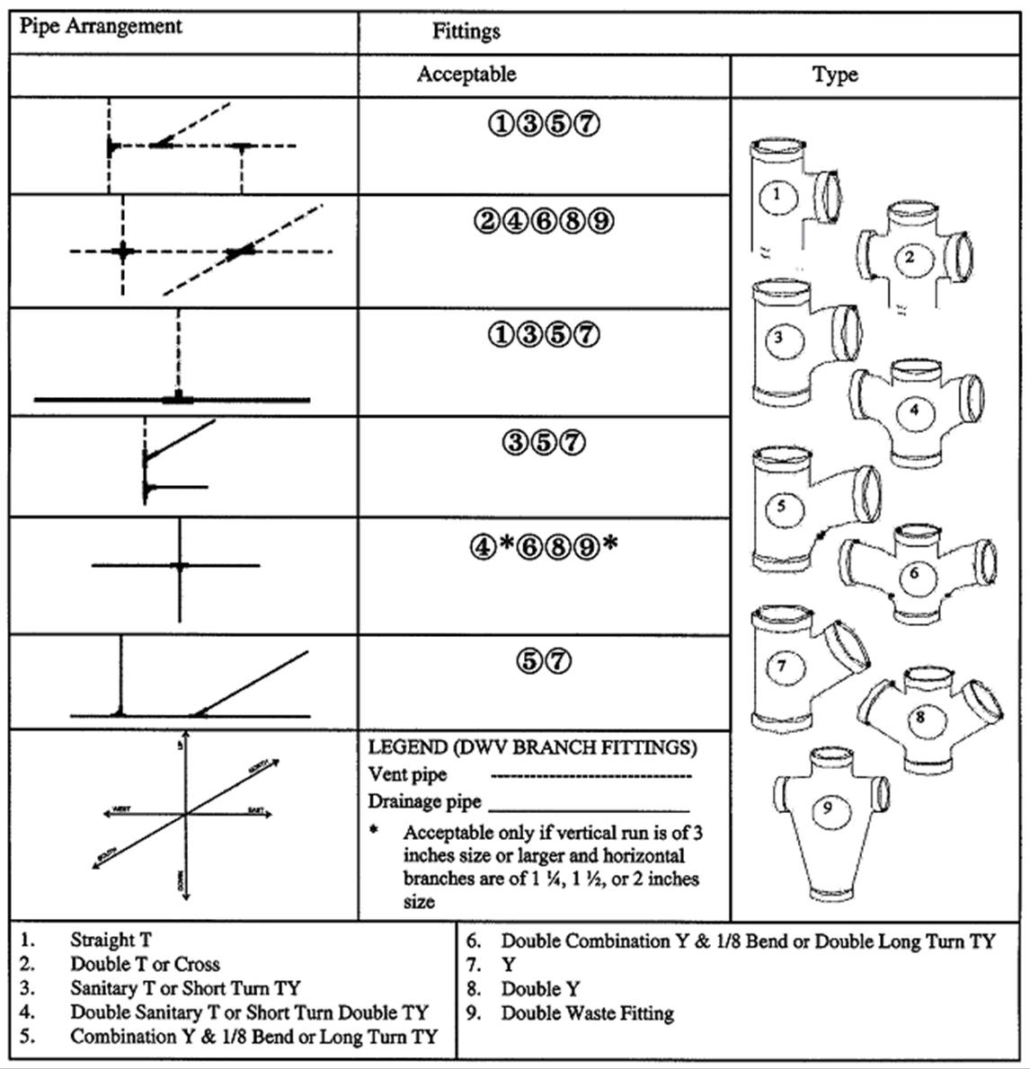
7.2.5. Non-Metallic Pipe and Fittings
7.2.5.1. Reserved
7.2.5.2. Reserved
7.2.5.3. Concrete Pipe and Fittings
(1) Concrete pipe shall conform to CSA-A257 Series, “Standards for Concrete Pipe and Manhole Sections”.
(2) Joints with external elastomeric gaskets shall be made with corrosion resistant external band type flexible mechanical couplings that conform to CSA B602, “Mechanical Couplings for Drain, Waste, and Vent Pipe and Sewer Pipe”.
(3) Concrete fittings field fabricated from lengths of pipe shall not be used.
(4) Concrete pipe shall not be used above ground inside a building.
(5) Precast reinforced circular concrete manhole sections, catch basins and fittings shall conform to CSA A257.4, “Precast Reinforced Circular Concrete Manhole Sections, Catch Basins, and Fittings”.
7.2.5.4. Vitrified Clay Pipe and Fittings
(1) Vitrified clay pipe and fittings shall be certified to CSA A60.1-M, “Vitrified Clay Pipe”.
(2) Couplings and joints for vitrified clay pipe shall be certified to CSA A60.3-M, “Vitrified Clay Pipe Joints”.
(3) Vitrified clay pipe and fittings shall not be used except for an underground part of a drainage system.
7.2.5.5. Polyethylene Pipe and Fittings
(1) Polyethylene water pipe, tubing and fittings shall be certified to, and have a pressure rating meeting the requirements of, Series 160 or a higher series of CSA B137.1, “Polyethylene (PE) Pipe, Tubing and Fittings for Cold Water Pressure Services”.
(2) Except as permitted in Sentence 7.2.5.7.(1), polyethylene water pipe shall not be used except for a water service pipe.
(3) Butt fusion fittings for polyethylene pipe shall conform to ASTM D3261, “Butt Heat Fusion Polyethylene (PE) Plastic Fittings for Polyethylene (PE) Plastic Pipe and Tubing”.
7.2.5.6. Polyethylene Pipe Used Underground
(1) Polyethylene pipe used underground in a drainage system for rehabilitation of existing systems using trenchless technology shall conform to ASTM F714, “Polyethylene (PE) Plastic Pipe (DR-PR) Based on Outside Diameter” and shall be HDPE 3408, SDR 17 or heavier.
7.2.5.7. Crosslinked Polyethylene Pipe and Fittings
(1) Cross-linked polyethylene pipe and its associated fittings used in hot and cold potable water systems shall be certified to CSA B137.5, “Crosslinked Polyethylene (PEX) Tubing Systems for Pressure Applications”.
7.2.5.8. PVC Pipe and Fittings
(1) PVC water pipe, fittings and solvent cement shall be certified to CSA B137.3, “Rigid Polyvinylchloride (PVC) Pipe and Fittings for Pressure Applications” or CSA B137.2, “Polyvinylchloride (PVC) Injection-Moulded Gasketed Fittings for Pressure Applications”, and have a minimum pressure rating of 1 100 kPa.
(2) PVC water pipe and fittings in Sentence (1) shall not be used in a hot water system.
7.2.5.9. CPVC Pipe, Fittings and Solvent Cements
(1) CPVC hot and cold water pipe, fittings and solvent cements shall be certified to CSA B137.6, “Chlorinated Polyvinylchloride (CPVC) Pipe, Tubing and Fittings for Hot and Cold Water Distribution Systems”.
(2) The design temperature and design pressure of a CPVC piping system shall conform to Table 7.2.5.9.
Table 7.2.5.9.
Maximum Permitted Pressure for CPVC Piping at Various Temperatures
Forming part of Sentence 7.2.5.9.(2)
| Item | Column 1 Maximum Temperature of Water, °C | Column 2 Maximum Permitted Pressures, kPa |
| 1. | 10 | 3150 |
| 2. | 20 | 2900 |
| 3. | 30 | 2500 |
| 4. | 40 | 2100 |
| 5. | 50 | 1700 |
| 6. | 60 | 1300 |
| 7. | 70 | 1000 |
| 8. | 82 | 690 |
7.2.5.10. Plastic Pipe, Fittings and Solvent Cement Used Underground
(1) Plastic pipe, fittings and solvent cement used underground outside a building or under a building in a drainage system shall be certified to,
(a) ASTM F628, “Acrylonitrile-Butadiene-Styrene (ABS) Schedule 40 Plastic Drain, Waste and Vent Pipe With a Cellular Core”,
(b) CAN/CSA-B181.1, “Acrylonitrile-Butadiene-Styrene (ABS) Drain, Waste, and Vent Pipe and Pipe Fittings”,
(c) CAN/CSA-B181.2, “Polyvinylchloride (PVC) and Chlorinated Polyvinylchloride (CPVC) Drain, Waste, and Vent Pipe and Pipe Fittings”,
(d) CAN/CSA-B182.1, “Plastic Drain and Sewer Pipe and Pipe Fittings”,
(e) CAN/CSA-B182.2, “PSM Type Polyvinylchloride (PVC) Sewer Pipe and Fittings”,
(f) CAN/CSA-B182.4, “Profile Polyvinylchloride (PVC) Sewer Pipe and Fittings”,
(g) CAN/CSA-B182.6, “Profile Polyethylene (PE) Sewer Pipe and Fittings for Leak-Proof Sewer Applications”,
(g.1) CAN/CSA-B182.8, “Profile Polyethylene (PE) Storm Sewer and Drainage Pipe and Fittings”, for Type 1 joints and non-perforated pipes,
(h) CSA B137.2, “Polyvinylchloride (PVC) Injection-Moulded Gasketed Fittings for Pressure Applications”, or
(i) CSA B137.3, “Rigid Polyvinylchloride (PVC) Pipe and Fittings for Pressure Applications”.
(2) Except as permitted in Clauses (h) and (i), plastic pipe used as described in Sentence (1) shall have a stiffness equal or greater than 320 kPa.
7.2.5.11. Transition Solvent Cement
(1) Solvent cement for transition joints shall conform to,
(a) CAN/CSA-B181.1, “Acrylonitrile-Butadiene-Styrene (ABS) Drain, Waste, and Vent Pipe and Pipe Fittings”, or
(b) CAN/CSA-B181.2, “Polyvinylchloride (PVC) and Chlorinated Polyvinylchloride (CPVC) Drain, Waste, and Vent Pipe and Pipe Fittings”.
(2) Transition solvent cement shall only be used for joining an ABS plumbing system to a PVC plumbing system.
7.2.5.12. Plastic Pipe, Fittings and Solvent Cement Used in Buildings
(1) Plastic pipe, fittings and solvent cement used inside or under a building in a sanitary drainage system or venting system shall be certified to,
(a) ASTM F628, “Acrylonitrile-Butadiene-Styrene (ABS) Schedule 40 Plastic Drain, Waste, and Vent Pipe With a Cellular Core”,
(b) CAN/CSA-B181.1, “Acrylonitrile-Butadiene-Styrene (ABS) Drain, Waste, and Vent Pipe and Pipe Fittings”, or
(c) CAN/CSA-B181.2, “Polyvinylchloride (PVC) and Chlorinated Polyvinylchloride (CPVC) Drain, Waste, and Vent Pipe and Pipe Fittings”.
(2) Plastic pipe, fittings and solvent cement used inside a building in a storm drainage system shall be certified to,
(a) ASTM F628, “Acrylonitrile-Butadiene-Styrene (ABS) Schedule 40 Plastic Drain, Waste, and Vent Pipe With a Cellular Core”,
(b) CAN/CSA-B181.1, “Acrylonitrile-Butadiene-Styrene (ABS) Drain, Waste, and Vent Pipe and Pipe Fittings”,
(c) CAN/CSA-B181.2, “Polyvinylchloride (PVC) and Chlorinated Polyvinylchloride (CPVC) Drain, Waste, and Vent Pipe and Pipe Fittings”,
(d) CAN/CSA-B182.1, “Plastic Drain and Sewer Pipe and Pipe Fittings”, or
(e) CAN/CSA-B182.2, “PSM Type Polyvinylchloride (PVC) Sewer Pipe and Fittings”.
(3) Plastic pipe used as described in Sentence (2) shall have a pipe stiffness equal or greater than 320 kPa.
(4) Requirements for combustible piping in relation to fire safety shall conform to Sentences 3.1.5.16.(1) and 9.10.9.6.(2) to (8) and Articles 3.1.9.4. and 9.10.9.7.
(5) Where noncombustible piping pierces a fire separation or a fire block, the requirements for fire stopping of Subsection 3.1.9., Sentence 9.10.9.6.(1) and Article 9.10.16.4. shall apply.
7.2.5.13. Polyethylene/Aluminum/Polyethylene Composite Pipe and Fittings
(1) PE/AL/PE composite pipe and fittings used for potable water systems shall conform to CSA B137.9, “Polyethylene/Aluminum/Polyethylene (PE-AL-PE) Composite Pressure-Pipe Systems”.
(2) Except as provided in Sentences (3) and (4), PE/AL/PE pipe and fittings shall not be used in a hot water system.
(3) PE/AL/PE pipe with a pressure rating of 690 kPa or greater at 82ºC shall be permitted in a hot water system.
(4) PE/AL/PE pipe with a pressure rating of 690 kPa or greater at 82ºC shall be used with fittings that conform to CSA B137.10, “Crosslinked Polyethylene/Aluminum/Crosslinked Polyethylene (PEX-AL-PEX) Composite Pressure-Pipe Systems”, in a hot water system.
7.2.5.14. Crosslinked Polyethylene/Aluminum/Polyethylene Composite Pipe and Fittings
(1) PEX/AL/PEX composite pipe and fittings used for potable water systems shall conform to CSA B137.10, “Crosslinked Polyethylene/Aluminum/Crosslinked Polyethylene (PEX-AL-PEX) Composite Pressure-Pipe Systems”.
7.2.5.15. Polypropylene Pipe and Fittings
(1) Polypropylene pipe and fittings used for hot and cold potable water systems shall conform to CSA B137.11, “Polypropylene (PP-R) Pipe and Fittings for Pressure Applications”.
7.2.6. Ferrous Pipe and Fittings
7.2.6.1. Cast Iron Frames, Covers, Drainage and Vent Pipe and Fittings
(1) Drainage piping, vent piping and fittings made of cast iron shall be certified to CAN/CSA-B70, “Cast Iron Soil Pipe, Fittings and Means of Joining”.
(2) Cast iron soil pipe and fittings shall not be used in a water system.
(3) Cast iron frames and covers for maintenance holes and catch basins shall conform to CAN/CSA-B70.1, “Frames and Covers for Maintenance Holes and Catchbasins”.
7.2.6.2. Reserved
7.2.6.3. Threaded Cast Iron Drainage Fittings
(1) Threaded cast iron drainage fittings shall conform to ASME B16.12, “Cast Iron Threaded Drainage Fittings”.
(2) Threaded cast iron drainage fittings shall not be used in a water system.
7.2.6.4. Cast Iron Water Pipe
(1) Cast iron water pipes shall conform to ANSI/AWWA C151/A21.51, “Ductile-Iron Pipe, Centrifugally Cast”.
(2) Cement-mortar lining for cast iron water pipes shall conform to ANSI/AWWA C104/A21.4, “Cement-Mortar Lining for Ductile-Iron Pipe and Fittings”.
(3) Cast iron fittings for cast iron or ductile-iron water pipes shall conform to ANSI/AWWA C110/A21.10, “Ductile-Iron and Gray-Iron Fittings”.
(4) Rubber gasket joints for cast iron and ductile-iron pressure pipe for water piping shall conform to ANSI/AWWA C111/A21.11, “Rubber-Gasket Joints for Ductile-Iron Pressure Pipe and Fittings”.
7.2.6.5. Screwed Cast Iron Water Fittings
(1) Screwed cast iron water fittings shall conform to ASME B16.4, “Gray Iron Threaded Fittings: Classes 125 and 250”.
(2) Screwed cast iron water fittings used in a water system shall be cement-mortar lined or galvanized.
(3) Screwed cast iron water fittings shall not be used in a drainage system.
7.2.6.6. Screwed Malleable Iron Water Fittings
(1) Screwed malleable iron water fittings shall conform to ASME B16.3, “Malleable Iron Threaded Fittings: Classes 150 and 300”.
(2) Screwed malleable iron water fittings used in a water system shall be cement-mortar lined or galvanized.
(3) Screwed malleable iron water fittings shall not be used in a drainage system.
7.2.6.7. Steel Pipe
(1) Except as provided in Sentences (2) and (3), welded and seamless steel pipe shall not be used in a plumbing system.
(2) Galvanized steel pipe may be used in a drainage system or a venting system above ground inside a building.
(3) Galvanized steel pipe and fittings shall not be used in a water distribution system except,
(a) in buildings of industrial occupancy, or
(b) for the repair of existing galvanized steel piping systems.
(4) Galvanized steel pipe and fittings shall conform to ASTM A53/A53M, “Pipe, Steel, Black and Hot Dipped, Zinc-Coated Welded and Seamless”.
(5) Where galvanized steel pipe is used in a drainage system, it shall be used with drainage fittings.
(6) All steel pipe of 4 in. size and smaller shall be schedule 40 or heavier and fittings of less than 2 in. size shall be galvanized screw fittings.
7.2.6.8. Corrugated Steel Pipe and Couplings
(1) Corrugated steel pipe and couplings shall be certified to CAN/CSA-G401, “Corrugated Steel Pipe Products”.
(2) Corrugated steel pipe shall only be used underground outside a building in a storm drainage system.
(3) Couplings for corrugated steel pipe shall be constructed so that when installed they shall,
(a) maintain the pipe alignment,
(b) resist the separation of adjoining lengths of pipe,
(c) prevent root penetration, and
(d) prevent the infiltration of surrounding material.
7.2.6.9. Sheet Metal Leaders
(1) A sheet metal leader shall not be used except above ground outside a building.
7.2.6.10. Stainless Steel Pipe
(1) Stainless steel pipe shall conform to,
(a) ASME B36.19M, “Stainless Steel Pipe”, and
(b) ASTM A312 / A312M, “Seamless, Welded, and Heavily Cold Worked Stainless Steel Pipes”.
(2) Only grade 304/304L or 316/316L stainless steel pipe shall be used.
7.2.6.11. Stainless Steel Butt Weld Pipe Fittings
(1) Stainless steel butt weld pipe fittings shall conform to,
(a) ASME B16.9, “Factory-Made Wrought Buttwelding Fittings”, and
(b) ASTM A403 / A403M, “Wrought Austenitic Stainless Steel Piping Fittings”.
(2) Stainless steel butt weld pipe fittings shall be made of a material that matches the grade of the pipe material used.
7.2.6.12. Stainless Steel Pipe Flanges
(1) Stainless steel pipe flanges shall,
(a) conform to ASME B16.5, “Pipe Flanges and Flanged Fittings: NPS ½ through NPS 24 Metric/Inch Standard”, and
(b) conform to ASTM A182 / A182M, “Forged or Rolled Alloy and Stainless Steel Pipe Flanges, Forged Fittings, and Valves and Parts for High-Temperature Service”, or AWWA C228, “Stainless-Steel Pipe Flanges For Water Service – Sizes 2 in. through 72 in. (50 mm through 1 800 mm)”.
(2) Stainless steel pipe flanges shall be made of a material that matches the grade of the pipe material used.
7.2.6.13. Stainless Steel Threaded Fittings
(1) Stainless steel threaded fittings shall be Schedule 40 or greater and shall conform to,
(a) ASTM A182 / A182M, “Forged or Rolled Alloy and Stainless Steel Pipe Flanges, Forged Fittings, and Valves and Parts for High-Temperature Service”, or
(b) ASTM A351 / A351M, “Castings, Austenitic, for Pressure-Containing Parts”.
(2) Stainless steel threaded fittings shall be made of a material that matches the grade of the pipe material used.
7.2.6.14. Stainless Steel Tube
(1) Stainless steel tube shall conform to,
(a) ASME B16.9, “Factory-Made Wrought Buttwelding Fittings”, and
(b) ASTM A269, “Seamless and Welded Austenitic Stainless Steel Tubing for General Service”.
(2) Only grade 304/304L or 316/316L stainless steel tubes shall be used.
7.2.6.15. Stainless Steel Pipe and Tube
(1) The use of stainless steel pipe and tube shall conform to Table 7.2.6.15.
Table 7.2.6.15.
Permitted Use of Stainless Steel Tube and Pipe
Forming Part of Sentence 7.2.6.15.(1)
| Item | Column 1 Stainless Steel Tube or Pipe | Column 2 Underground Water Distribution System | Column 3 Above-ground Water Distribution System | Column 4 Building Sewer | Column 5 Underground Drainage System | Column 6 Above-ground Drainage System | Column 7 Underground Venting System | Column 8 Above-ground Venting System |
| 1. | Stainless steel pipe | P | P | P | P | P | P | P |
| 2. | Stainless steel tube | P | P | N | N | N | N | N |
Notes to Table 7.2.6.15.:
P — Permitted
N — Not Permitted
7.2.7. Non-Ferrous Pipe and Fittings
7.2.7.1. Copper and Brass Pipe
(1) Copper pipe shall conform to ASTM B42, “Seamless Copper Pipe, Standard Sizes”.
(2) Brass pipe shall conform to ASTM B43, “Seamless Red Brass Pipe, Standard Sizes”.
7.2.7.2. Brass or Bronze Pipe Flanges and Flanged Fittings
(1) Brass or bronze pipe flanges and flanged fittings shall conform to ASME B16.24, “Cast Copper Alloy Pipe Flanges and Flanged Fittings: Classes 150, 300, 600, 900, 1500 and 2500”.
7.2.7.3. Brass or Bronze Threaded Water Fittings
(1) Brass or bronze threaded water fittings shall conform to ASME B16.15, “Cast Copper Alloy Threaded Fittings: Classes 125 and 250”.
(2) Brass or bronze threaded water fittings shall not be used in a drainage system.
7.2.7.4. Copper Tube
(1) Copper tube in a plumbing system shall,
(a) be certified to ASTM B88, “Seamless Copper Water Tube”, or
(b) comply with ASTM B306, “Copper Drainage Tube (DWV)”.
(2) The use of copper tube shall conform to Table 7.2.7.4.
Table 7.2.7.4.
Permitted Use of Copper Tube and Pipe
Forming Part of Sentence 7.2.7.4.(2)
| Item | Column 1 Type of Copper Tube or Pipe | Column 2 Underground Water Distribution System | Column 3 Above-ground Water Distribution System | Column 4 Building Sewer | Column 5 Underground Drainage System | Column 6 Above-ground Drainage System | Column 7 Underground Venting System | Column 8 Above-ground Venting System |
| 1. | K & L hard | N | P | P | P | P | P | P |
| 2. | K & L soft | P | P | N | N | N | N | N |
| 3. | M hard | N | P | N | N | P | N | P |
| 4. | M soft | N | N | N | N | N | N | N |
| 5. | DWV | N | N | N | N | P | N | P |
Notes to Table 7.2.7.4.:
P — Permitted
N — Not Permitted
(3) Copper tube used in a plumbing appliance shall conform to,
(a) ASTM B88, “Seamless Copper Water Tube”, or
(b) ASTM B68 / B68M, “Seamless Copper Tube, Bright Annealed”.
(4) Type K or L copper tube shall be used for the potable water side of a heat exchanger in a pre-engineered wastewater heat recovery system.
(5) Copper tube shall not be used for the fixture drain or the portion of the vent pipe below the flood level rim of manually flushing or waterless urinals.
7.2.7.5. Solder-Joint Drainage Fittings
(1) Solder-joint fittings for drainage systems shall conform to,
(a) ASME B16.23, “Cast Copper Alloy Solder Joint Drainage Fittings: DWV”, or
(b) ASME B16.29, “Wrought Copper and Wrought Copper Alloy Solder Joint Drainage Fittings – DWV”.
(2) Solder-joint fittings for drainage systems shall not be used in a water system.
7.2.7.6. Solder-Joint Water Fittings
(1) Except as provided in Sentence (2), solder-joint fittings for water systems shall conform to,
(a) ASME B16.18, “Cast Copper Alloy Solder Joint Pressure Fittings”, or
(b) ASME B16.22, “Wrought Copper and Copper Alloy Solder Joint Pressure Fittings”.
(2) Solder-joint fittings for water systems not made by casting or the wrought process shall conform to the applicable requirements of ASME B16.18, “Cast Copper Alloy Solder Joint Pressure Fittings”.
7.2.7.7. Flared-Joint Fittings for Copper Tube Water Systems
(1) Flared-joint fittings for copper tube water systems shall conform to ASME B16.26, “Cast Copper Alloy Fittings for Flared Copper Tubes”.
(2) Flared-joint fittings for copper tube water systems not made by casting shall conform to the applicable requirements of ASME B16.26, “Cast Copper Alloy Fittings for Flared Copper Tubes”.
7.2.7.8. Lead Waste Pipe and Fittings
(1) Lead waste pipe and fittings shall not be used in a water system or for a building sewer.
(2) When there is a change in size of a lead closet bend, the change shall be in the vertical section of the bend or made in such a manner that there shall be no retention of liquid in the bend.
7.2.8. Corrosion Resistant Materials
7.2.8.1. Pipe and Fittings
(1) Pipes and fittings to be used for drainage and venting of acid and corrosive wastes shall conform to,
(a) ASTM A518/A518M, “Corrosion-Resistant High-Silicon Iron Castings”,
(b) ASTM C1053, “Borosilicate Glass Pipe and Fittings for Drain, Waste, and Vent (DWV) Applications”, or
(c) CAN/CSA-B181.3, “Polyolefin and Polyvinylidene Fluoride (PVDF) Laboratory Drainage Systems”.
7.2.9. Jointing Materials
7.2.9.1. Cement-Mortar
(1) Cement-mortar shall not be used for jointing.
7.2.9.2. Solder and Fluxes
(1) Solders for solder joint fittings shall conform to ASTM B32, “Solder Metal” in accordance with the recommended use.
(2) Solders and fluxes having a lead content in excess of 0.2 per cent shall not be used in a potable water system.
(3) Fluxes for soldered joints shall conform to ASTM B813, “Liquid and Paste Fluxes for Soldering of Copper and Copper Alloy Tube”.
(4) Brazing alloys shall conform to ANSI/AWS A5.8M/A5.8, “Filler Metals for Brazing and Braze Welding”, BCuP range.
7.2.10. Miscellaneous Materials
7.2.10.1. Floor Flanges
(1) Brass floor flanges shall be certified to CSA B158.1, “Cast Brass Solder Joint Drainage, Waste and Vent Fittings”.
(2) ABS floor flanges shall be certified to CAN/CSA-B181.1, “Acrylonitrile-Butadiene-Styrene (ABS) Drain, Waste, and Vent Pipe and Pipe Fittings”.
(3) PVC floor flanges shall be certified to CAN/CSA-B181.2, “Polyvinylchloride (PVC) and Chlorinated Polyvinylchloride (CPVC) Drain, Waste, and Vent Pipe and Pipe Fittings”.
(4) Cast iron, copper and aluminum floor flanges shall be suitable for the purpose.
7.2.10.2. Screws, Bolts, Nuts and Washers
(1) Every screw, bolt, nut and washer shall be of materials that are resistant to corrosion, when used,
(a) to connect a water closet to a floor flange,
(b) to anchor the floor flange to the floor,
(c) to anchor the water closet to the floor, or
(d) to hold cleanout covers or floor drain grates.
7.2.10.3. Cleanout Fittings
(1) Every plug, cap, nut or bolt that is intended to be removable from a ferrous fitting shall be of a non-ferrous material.
(2) A cleanout fitting that as a result of normal maintenance operations cannot withstand the physical stresses of removal and reinstallation or cannot ensure a gas-tight seal shall not be installed.
(3) A screw cap or test cap shall not be used as a cleanout plug or cover.
7.2.10.4. Mechanical Couplings
(1) Groove and shoulder type mechanical pipe couplings shall conform to CSA B242, “Groove and Shoulder Type Mechanical Pipe Couplings”.
(2) Mechanical Couplings for DWV and Sewer Pipe shall be certified to CSA B602, “Mechanical Couplings for Drain, Waste, and Vent Pipe and Sewer Pipe”.
7.2.10.5. Saddle Hubs
(1) Except as provided in Sentence (2), a saddle hub or fitting shall not be installed in drainage systems, venting systems or water systems.
(2) A saddle hub or saddle clamp may be installed in a building drain or building sewer of nominal diameter not less than 8 in. and that is in service provided that the connecting branch is at least two pipe sizes smaller than the run of the building drain or building sewer to which it is connected.
7.2.10.6. Supply and Waste Fittings
(1) Supply fittings shall conform to ASME A112.18.1 / CSA B125.1, “Plumbing Supply Fittings” or CSA B125.3, “Plumbing Fittings”.
(2) Waste fittings shall conform to ASME A112.18.2 / CSA B125.2, “Plumbing Waste Fittings”.
7.2.10.7. Linings and Coatings of Domestic Water Tanks
(1) Linings and coatings of domestic water tanks that come into contact with potable water shall be certified to NSF/ANSI 61, “Drinking Water System Components - Health Effects”.
7.2.10.8. Direct Flush Valves
(1) Every direct flush valve shall,
(a) open fully and close positively under service pressure,
(b) complete its cycle of operation automatically,
(c) be provided with a means of regulating the volume of water that it discharges, and
(d) be provided with a vacuum breaker unless the fixture is designed so that back-siphonage cannot occur.
7.2.10.9. Drinking Fountain Bubblers
(1) The orifice of every drinking fountain bubbler shall,
(a) be of the shielded type, and
(b) direct the water upward to an angle of approximately 45°.
(2) Every drinking fountain bubbler shall include a means of regulating the flow to the orifice.
7.2.10.10. Back-Siphonage Preventers and Backflow Preventers
(1) Except as provided in Sentence (2), back-siphonage preventers and backflow preventers shall be certified to,
(a) CSA B64.0, “Definitions, General Requirements and Test Methods for Vacuum Breakers and Backflow Preventers”,
(b) CSA B64.1.1, “Atmospheric Vacuum Breakers (AVB)”,
(c) CSA B64.1.2, “Pressure Vacuum Breakers (PVB)”,
(d) CSA B64.1.3, “Spill-resistant Pressure Vacuum Breakers (SRPVB)”,
(e) CSA B64.1.4, “Vacuum Breaker, Air Space Type (ASVB)”,
(f) CSA B64.2, “Hose Connection Vacuum Breakers (HCVB)”,
(g) CSA B64.2.1, “Hose Connection Vacuum Breakers (HCVB) with Manual Draining Feature”,
(h) CSA B64.2.1.1, “Hose Connection Dual Check Vacuum Breakers (HCDVB)”,
(i) CSA B64.2.2, “Hose Connection Vacuum Breakers (HCVB) with Automatic Draining Feature”,
(j) CSA B64.3, “Dual Check Valve Backflow Preventers with Atmospheric Port (DCAP)”,
(k) CSA B64.3.1, “Dual Check Valve Backflow Preventers with Atmospheric Port for Carbonators (DCAPC)”,
(l) CSA B64.4, “Reduced Pressure Principle (RP) Backflow Preventers”,
(m) CSA B64.5, “Double Check Valve (DCVA) Backflow Preventers”,
(n) CSA B64.6, “Dual Check Valve (DuC) Backflow Preventers”,
(o) CSA B64.7, “Laboratory Faucet Vacuum Breakers (LFVB)”,
(p) CSA B64.8, “Dual Check Valve Backflow Preventers with Intermediate Vent (DuCV)”, or
(q) CSA B64.10, “Selection and Installation of Backflow Preventers”.
(2) Back-siphonage preventers (anti-siphon fill valves) for tank type water closets shall be certified to CSA B125.3, “Plumbing Fittings”.
7.2.10.11. Relief Valves
(1) Temperature relief, pressure relief, combined temperature and pressure relief and vacuum relief valves shall conform to ANSI Z21.22 / CSA 4.4, “Relief Valves for Hot Water Supply Systems”.
7.2.10.12. Reducing Valves
(1) Direct acting water pressure reducing valves for domestic water supply systems shall conform to CAN/CSA-B356, “Water Pressure Reducing Valves for Domestic Water Supply Systems”.
7.2.10.13. Solar Domestic Hot Water
(1) Equipment forming part of a packaged system for solar heating of potable water, shall conform to CAN/CSA-F379.1, “Packaged Solar Domestic Hot Water Systems (Liquid-to-Liquid Heat Transfer) for All-Season Use”.
7.2.10.14. Vent Pipe Flashing
(1) Flashing fabricated on site for vent pipes shall be fabricated from,
(a) copper sheet at least 0.33 mm thick,
(b) aluminum sheet at least 0.48 mm thick,
(c) alloyed zinc sheet at least 0.35 mm thick,
(d) lead sheet at least 1.73 mm thick,
(e) galvanized steel sheet at least 0.33 mm thick, or
(f) polychloroprene (neoprene) at least 2.89 mm thick.
(2) Prefabricated flashing for vent pipes shall be certified to CSA B272, “Prefabricated Self-Sealing Roof Vent Flashings”.
7.2.10.15. Water Hammer Arresters
(1) Factory built water hammer arresters shall conform to ANSI/ASSE 1010, “Water Hammer Arresters”.
7.2.10.16. Air Admittance Valves
(1) Air admittance valves shall conform to ASSE 1051, “Individual and Branch Type Air Admittance Valves for Sanitary Drainage Systems”.
7.2.10.17. Drinking Water Treatment Systems
(1) A drinking water treatment system or device shall be certified to CAN/CSA-B483.1, “Drinking Water Treatment Systems”.
7.2.11. Water Service Pipes and Fire Service Mains
7.2.11.1. Design, Construction, Installation and Testing
(1) Except as provided in Articles 7.2.11.2. to 7.2.11.4., and 7.3.7.2, the design, construction, installation and testing of fire service mains and water service pipe combined with fire service mains shall be in conformance with NFPA 24, “Installation of Private Fire Service Mains and Their Appurtenances”.
7.2.11.2. Certification or Conformance
(1) Water service pipes and fire service mains shall be certified or conform to the standards for the materials listed in Table 7.2.11.2.
Table 7.2.11.2.
Water Service Pipe and Fire Service Main Materials
Forming Part of Sentence 7.2.11.2.(1)
| Item | Column 1 Material | Column 2 Standard | Column 3 Limitations |
| 1. | Polyethylene pipe and fittings | Certified to Series 160 or a higher series of CSA B137.1, “Polyethylene (PE) Pipe, Tubing and Fittings for Cold Water Pressure Services” |
|
| 2. | Crosslinked polyethylene pressure pipe or tube and fittings | Certified to CSA B137.5, “Crosslinked Polyethylene (PEX) Tubing Systems for Pressure Applications” |
|
| 3. | PVC pipe and fittings | Certified to CSA B137.3, “Rigid Polyvinylchloride (PVC) Pipe and Fittings for Pressure Applications”, or certified to CSA B137.2, “Polyvinylchloride (PVC) Injection-Moulded Gasketed Fittings for Pressure Applications” | Pipe and fittings must have a rated working pressure of 1 100 kPa or more |
| 4. | CPVC pipe and fittings | Certified to CSA B137.6, “Chlorinated Polyvinylchloride (CPVC) Pipe, Tubing and Fittings for Hot and Cold Water Distribution Systems” | The design temperature and pressure shall conform to the requirements of the CSA B137.6, “Chlorinated Polyvinylchloride (CPVC) Pipe, Tubing and Fittings for Hot and Cold Water Distribution Systems” |
| 5. | Cast iron water pipe | Conform to ANSI/AWWA C151/A21.51, “Ductile-Iron Pipe, Centrifugally Cast” | Pipe shall have a cement-mortar lining conforming to ANSI/AWWA C104/A21.4, “Cement-Mortar Lining for Ductile-Iron Pipe and Fittings” |
| 6. | Iron fittings for cast iron or ductile-iron water pipes | Conform to ANSI/AWWA C110/A21.10, “Ductile-Iron and Gray-Iron Fittings” | Pipe shall have a cement-mortar lining conforming to ANSI/AWWA C104/A21.4, “Cement-Mortar Lining for Ductile-Iron Pipe and Fittings” |
| 7. | Rubber gasket joints for cast iron and ductile-iron water pipes | Conform to ANSI/AWWA C111/A21.11, “Rubber Gasket Joints for Ductile-Iron Pressure Pipe and Fittings” |
|
| 8. | Screwed cast iron water fittings | Conform to ASME B16.4, “Gray Iron Threaded Fittings: Classes 125 and 250” | Screwed cast iron water fittings shall be cement-mortar lined or galvanized |
| 9. | Type K soft copper tube | Certified to ASTM B88, “Seamless Copper Water Tube” |
|
| 10. | Solder-joint fittings for copper water systems | Conform to ASME B16.18, “Cast Copper Alloy Solder Joint Pressure Fittings”, or conform to ASME B16.22, “Wrought Copper and Copper Alloy Solder-Joint Pressure Fittings” | Solder-joint fittings not made by casting or the wrought process shall conform to the applicable requirements of ASME B16.18, “Cast Copper Alloy Solder-Joint Pressure Fittings” |
| 11. | Flared-joint fittings for copper water systems | Conform to ASME B16.26, “Cast Copper Alloy Fittings for Flared Copper Tubes” | Flared-joint fittings not made by casting shall conform to ASME B16.26, “Cast Copper Alloy Fittings for Flared Copper Tubes” |
| 12. | PE/AL/PE pipe and fittings | Certified to CSA B137.9, “Polyethylene/Aluminum/ Polyethylene (PE-AL-PE) Composite Pressure-Pipe Systems” |
|
| 13. | PEX/AL/PEX pipe and fittings | Certified to CSA B137.10, “Crosslinked Polyethylene/ Aluminum/Crosslinked Polyethylene (PEX-AL-PEX) Composite Pressure-Pipe Systems” |
|
7.2.11.3. Tracer Wire
(1) Except as provided in Sentence (2), a 14 gauge TW solid copper light coloured plastic coated tracer wire shall be attached to every non-metallic water service pipe or fire service main.
(2) Where a water service pipe or fire service main is detectable without the tracer wire referenced in Sentence (1), the tracer wire may be omitted.
7.2.11.4. Required Check Valve
(1) Where a water service pipe is supplied with water by more than one drinking water system, a check valve shall be installed at each connection with a drinking water system.
(2) Where a fire service main is supplied with water by more than one source, a check valve shall be installed at each connection with a source of water.
Section 7.3. Piping
7.3.1. Application
7.3.1.1. Application
(1) This Section applies to the construction and use of joints and connections, and the arrangement, protection, support and testing of piping.
7.3.2. Construction and Use of Joints
7.3.2.1. Caulked Lead Drainage Joints
(1) Every caulked lead drainage joint shall be firmly packed with oakum and tightly caulked with lead to a depth of at least 25 mm.
(2) No paint, varnish or other coating shall be applied on the lead until after the joint has been tested.
(3) Caulked lead drainage joints shall not be used except for cast iron pipe in a drainage system or venting system, or between such pipe and,
(a) other ferrous pipe,
(b) brass and copper pipe,
(c) a caulking ferrule, or
(d) a trap standard.
(4) A length of hub and spigot pipe and pipe fittings in a drainage system shall be installed with the hub at the upstream end.
7.3.2.2. Wiped Joints
(1) Wiped joints shall not be used except for sheet lead or lead pipe, or between such pipe and copper pipe or a ferrule.
(2) Every wiped joint in straight pipe shall,
(a) be made of solder,
(b) have an exposed surface on each side of the joint at least 19 mm wide, and
(c) be at least 10 mm thick at the thickest part.
(3) Every wiped flanged joint shall be reinforced with a lead flange that is at least 19 mm wide.
7.3.2.3. Screwed Joints
(1) In making a screwed joint, the ends of the pipe shall be reamed or filed out to the size of the bore and all chips and cuttings shall be removed.
(2) No pipe-joint cement or paint shall be applied to the internal threads.
7.3.2.4. Solder Joints
(1) Soldered joints shall be made in accordance with ASTM B828, “Making Capillary Joints by Soldering of Copper and Copper Alloy Tube and Fittings”.
7.3.2.5. Flared Joints
(1) In making a flared joint, the pipe shall be expanded with a proper flaring tool.
(2) Flared joints shall not be used for hard (drawn) copper tube.
7.3.2.6. Mechanical Joints
(1) Mechanical joints shall be made with compounded elastomeric couplings or rings held by stainless steel or cast iron clamps or contained within a compression connection or groove and shoulder type mechanical coupling.
7.3.2.7. Cold-Caulked Joints
(1) Cold-caulked joints shall not be used except for bell and spigot pipe in a water system, a drainage system or a venting system.
(2) The caulking compound used in cold-caulked joints shall be applied according to the manufacturer’s directions.
(3) Every cold-caulked joint in a drainage system shall be firmly packed with oakum and tightly caulked with cold caulking compound to a depth of at least 25 mm.
7.3.2.8. Stainless Steel Welded Joints
(1) Stainless steel welded joints shall conform to ASME B31.9, “Building Services Piping”.
(2) Butt weld pipe fittings shall be at least as thick as the wall of the pipe used.
7.3.3. Joints and Connections
7.3.3.1. Drilled and Tapped Joints
(1) Except as provided in Sentences (2) to (4), no water distributing pipe, drainage pipe or fittings shall be drilled, tapped or swaged.
(2) A water distributing pipe may be drilled or tapped to provide for a mechanically extracted T in copper tubing of Type L or K provided that all branch connections shall be notched and dimpled to limit depth of insertion and conform to the inner contour of the main.
(3) A copper water distributing pipe of 1 in. size or larger may be mechanically swaged to permit the joining of other copper pipe of equal size.
(4) A drainage pipe or fitting may be drilled or tapped,
(a) to provide for the connection of a trap seal primer line,
(b) to connect a device designed to dispense germicidal or odour control chemicals or trap seal water to a floor drain downstream of a vacuum breaker or flush valve in a flush tube connected to a sanitary unit,
(c) to provide a hole for a branch connection to a drainage pipe, where the branch connection is made with a saddle hub as permitted by Article 7.2.10.5. and where the hole is drilled to provide a smooth clean hole of the required size and orientation, or
(d) to provide for the connection of pipe or fittings to metal or rigid plastic pipe and fittings where the pipe or fittings are thick enough to be threaded or are bossed for tapping.
(5) No pipe adaption shall be made by the use of a bushing that leaves a square edge or shoulder on the inside of the pipe or fitting.
7.3.3.2. Reserved
7.3.3.3. Prohibition of Welding of Pipes and Fittings
(1) Cast iron soil pipe and fittings shall not be welded.
(2) Galvanized steel pipe and fittings shall not be welded.
7.3.3.4. Unions and Slip Joints
(1) Running thread and packing nut connections and unions with a gasket seal shall not be used downstream of a trap weir in a drainage system or in a venting system.
(2) A slip joint shall not be used,
(a) in a venting system, or
(b) in a drainage system, except to connect a fixture trap to a fixture drain in an accessible location.
7.3.3.5. Increaser or Reducer
(1) Every connection between two pipes of different size shall be made with an increaser or a reducer fitting installed so that it will permit the system to be completely drained.
7.3.3.6. Connection of Dissimilar Materials
(1) Adapters, connectors or mechanical joints used to join dissimilar materials shall be designed to accommodate the required transition.
7.3.3.7. Connection of Roof Drain to Leader
(1) Every roof drain shall be securely connected to a leader and provision shall be made for expansion.
7.3.3.8. Connection of Floor Outlet Fixtures
(1) Every pedestal urinal, floor-mounted water closet or S-trap standard shall be connected to a fixture drain by a floor flange or other means of connection, except that a cast iron trap standard may be caulked to a cast iron pipe.
(2) Except as provided in Sentence (3), every floor flange shall be of brass.
(3) Where cast iron or plastic pipe is used, a floor flange of the same material may be used.
(4) Every floor flange and fixture shall be securely set on a firm base and fastened to the floor or trap flange of the fixture.
(4.1) Every joint in a floor flange or between a fixture and the drainage system shall be sealed with a resilient, watertight and gas-tight seal.
(5) Where a lead water closet stub is used, the length of the stub below the floor flange shall be at least 75 mm.
7.3.3.9. Expansion and Contraction
(1) The design and installation of every piping system shall, where necessary, include means to accommodate expansion and contraction of the piping system caused by temperature change or building shrinkage.
7.3.3.10. Copper Tube
(1) Types M and DWV copper tube shall not be bent.
(2) Bends in copper tubing of soft or bending temper shall be made with tools manufactured and sized for the purpose.
7.3.3.11. Indirect Connections
(1) Where a fixture or device is indirectly connected, the connections shall be made by terminating the fixture drain above the flood level rim of a directly connected fixture to form an air break.
(2) The size of the air break shall be at least 25 mm.
7.3.3.12. Copper Joints Used Underground
(1) Except as provided in Sentence (2), joints in copper tubes installed underground shall be,
(a) made with either flared or compression fittings, or
(b) brazed using a brazing alloy within the American Welding Society’s AWS-BCuP range.
(2) Compression fittings shall not be used underground under a building.
7.3.4. Support of Piping
7.3.4.1. Capability of Support
(1) Piping shall be provided with support that is capable of keeping the pipe in alignment and bearing the weight of the pipe and its contents.
(2) Every floor or wall mounted water closet bowl shall be securely attached to the floor or wall by means of a flange and shall be stable.
(3) Every wall mounted fixture shall be supported so that no strain is transmitted to the piping.
7.3.4.2. Independence of Support
(1) Piping, fixtures, tanks or devices shall be supported independently of each other.
7.3.4.3. Insulation of Support
(1) Where a hanger or support for copper tube or brass or copper pipe is of a material other than brass or copper, it shall be suitably separated and electrically insulated from the pipe or tube to prevent galvanic action.
(2) Where a hanger or support for stainless steel pipe or tube is of a material other than stainless steel, it shall be suitably separated and electrically insulated from the pipe or tube.
7.3.4.4. Support for Vertical Piping
(1) Except as provided in Sentence (2), vertical piping shall be supported at its base and at the floor level of alternate storeys by rests, each of which can bear the weight of pipe that is between it and the rest above it.
(2) The maximum spacing of supports shall be 7.5 m.
7.3.4.5. Support for Horizontal Piping
(1) Nominally horizontal piping that is inside a building shall be braced to prevent swaying and buckling and to control the effects of thrust.
(2) Nominally horizontal piping shall be supported so that,
(a) galvanized iron or steel pipe is supported at intervals not exceeding,
(i) 3.75 m if the pipe size is 6 in. or more, and
(ii) 2 500 mm if the pipe size is less than 6 in.,
(b) lead pipe is supported throughout its length,
(c) cast iron pipe is supported,
(i) at or adjacent to each hub or joint,
(ii) at intervals not exceeding 3 m, and
(iii) at intervals not exceeding 1 000 mm if the pipe has mechanical joints and the length of pipe between adjacent fittings is 300 mm or less,
(d) Reserved
(e) ABS or PVC plastic DWV pipe is supported,
(i) at intervals not exceeding 1 200 mm,
(ii) at the ends of branches,
(iii) at changes of direction or elevation, and
(iv) if the pipe is a fixture drain that is more than 1 000 mm in length, as close as possible to the trap,
(f) plastic water pipe is supported at intervals not exceeding 1 000 mm,
(g) copper tube and copper and brass pipe is supported at intervals not exceeding,
(i) 3 m if the tube or pipe is hard temper and larger than 1 in. in size,
(ii) 2 500 mm if the tube or pipe is hard temper and 1 in. in size or less, and
(iii) 2 500 mm if the tube is soft temper,
(h) aluminum DWV pipe is supported,
(i) at intervals not greater than 3 m,
(ii) at both sides of all joints,
(iii) at all branch ends,
(iv) at all points where there is a change in direction, and
(v) as close to all traps as possible,
(i) supports and hangers for aluminum DWV pipe shall have a broad support base and shall be free of burrs and rough edges to prevent abrasion of the pipe,
(j) where joints in the piping are less rigid than the pipe, the support points shall be selected so as to minimize the shear and bending forces imposed on the joints,
(k) PE/AL/PE or PEX/AL/PEX composite pipe is supported at intervals not exceeding 1 000 mm,
(l) PP-R plastic pipe is supported,
(i) at intervals not exceeding 1 000 mm,
(ii) at the end of branches, and
(iii) at changes of direction and elevation, and
(m) stainless steel pipe or tube is supported at intervals not exceeding,
(i) 3 000 mm if the pipe or tube size is 1 in. or more, and
(ii) 2 500 mm if the pipe or tube size is less than 1 in.
(3) Where plastic pipe or a composite pipe incorporating a plastic component is installed,
(a) the pipe shall be aligned without added strain on the piping,
(b) the pipe shall not be bent or pulled into position after being welded or joined, and
(c) hangers shall not compress, cut or abrade the pipe.
(4) Reserved
(5) Where hangers are used to support nominally horizontal piping, the hangers shall be,
(a) supported by metal rods of not less than,
(i) 6 mm diam for supporting pipe 2 in. or less in size,
(ii) 8 mm diam for supporting pipe 4 in. or less in size, and
(iii) 13 mm diam for supporting pipe over 4 in. in size, or
(b) solid or perforated metal straps not less than,
(i) 0.6 mm nominal thickness, 12 mm wide for pipe 2 in. or less in size, and
(ii) 0.8 mm nominal thickness, 18 mm wide for pipe 4 in. or less in size.
(6) Where a hanger is attached to concrete or masonry, it shall be fastened by metal or expansion-type plugs that are inserted or built into the concrete or masonry.
7.3.4.6. Support for Underground Horizontal Piping
(1) Except as provided in Sentence (2), nominally horizontal piping that is underground shall be supported on a base that is firm and continuous under the whole of the pipe.
(2) Nominally horizontal piping installed underground that is not supported as described in Sentence (1) may be installed using hangers fixed to a foundation or structural slab provided that the hangers are capable of,
(a) keeping the pipe in alignment, and
(b) supporting the weight,
(i) of the pipe,
(ii) its contents, and
(iii) the fill over the pipe.
7.3.4.7. Support for Vent Pipe Above a Roof
(1) Where a vent pipe terminates above the surface of a roof, it shall be supported or braced to prevent misalignment.
7.3.4.8. Compression Fittings
(1) No compression fitting connecting to plain end pipe or tube shall be used in a plumbing system unless the pipe or tube and fittings are sufficiently stayed, clamped, anchored or buttressed so as to prevent separation during normal service of the system allowing for surge pressures.
7.3.4.9. Thrust Restraint of Water Service Pipes
(1) Pipe clamps and tie-rods, thrust blocks, locked mechanical or push-on joints, mechanical joints utilizing set screw retainer glands, or other suitable means of thrust restraint shall be provided at each change of direction of a water service pipe 4 in. or more in size and at all tees, plugs, caps and bends.
(2) Backing for underground water service pipes shall be placed,
(a) between undisturbed earth and the fitting to be restrained and shall be of sufficient bearing area to provide adequate resistance to the thrust to be encountered, and
(b) so that the joints will be accessible for inspection and repair.
(3) Concrete thrust blocks shall have a minimum compressive strength of not less than 10 MPa after 28 days.
(4) Thrust blocks shall not be used to restrain vertical pipe.
7.3.5. Protection of Piping
7.3.5.1. Backfill of Pipe Trench
(1) Where piping is installed underground, the backfill shall be carefully placed and tamped to a height of 300 mm over the top of the pipe and shall be free of stones, boulders, cinders and frozen earth.
7.3.5.2. Protection of Non-Metallic Pipe
(1) Where vitrified clay is located less than 600 mm below a basement floor and the floor is constructed of other than 75 mm or more of concrete, the pipe shall be protected by a 75 mm layer of concrete installed above the pipe.
7.3.5.3. Isolation from Loads
(1) Where piping passes through or under a wall, it shall be installed so that the wall does not bear on the pipe.
7.3.5.4. Protection from Frost
(1) Where piping may be exposed to freezing conditions, it shall be protected from the effects of freezing.
7.3.5.5. Protection from Mechanical Damage
(1) Plumbing, piping and equipment exposed to mechanical damage shall be protected.
7.3.5.6. Protection from Condensation
(1) Piping used for internal leaders, which may be subject to condensation, shall be installed in a manner that limits the risk of damage to the building due to condensation.
7.3.5.7. Spatial Separation
(1) Except as permitted in Sentences (2) and (3), a buried water service pipe shall be separated from the building drain, building sewer and a private sewage disposal system, by not less than 2 440 mm measured horizontally, of undisturbed or compacted earth.
(2) The water service pipe may be closer than 2 440 mm or be placed in the same trench with the building drain or building sewer if,
(a) the following conditions are met:
(i) the bottom of the water service pipe at all points is at least 500 mm above the top of the building drain or building sewer, and
(ii) when in a common trench with the building drain or building sewer, the water service pipe is placed on a shelf at one side of the common trench,
(b) the water service pipe is constructed of a single run of pipe with no joints or fittings between the street line or source of supply on the property and the inside face of the building, or
(c) the building drain or building sewer is constructed of piping which is pressure tested in accordance with Subsection 7.3.7. at 345 kPa.
(3) A buried water service pipe may pass under a building drain or building sewer if,
(a) a vertical separation of not less than 500 mm is provided between the invert of the building drain or building sewer and the crown of the water service pipe,
(b) adequate structural support is provided for the building drain or building sewer to prevent excessive deflection of joints and settling, and
(c) the length of the water service pipe is located so that there are no joints within 2 440 mm measured horizontally from the intersection with the building drain or building sewer.
(4) A buried water service pipe shall be constructed of a single run of pipe with no joints or fittings between the street line or source of supply on the property and the inside face of the building if the water service pipe is less than 15 m from,
(a) a private sewage disposal system, or
(b) a source of pollution other than a private sewage disposal system.
7.3.6. Testing of Drainage and Venting Systems
7.3.6.1. Tests and Inspection of Drainage or Venting Systems
(1) Except in the case of an external leader, after a section of drainage system or a venting system has been roughed in, and before any fixture is installed or piping is covered, a water or an air test shall be conducted.
(2) Where a chief building official requires a final test, it shall be carried out after every fixture is installed and before any part of the drainage system or venting system is placed in operation.
(3) Where a prefabricated system is assembled off the building site in such a manner that it cannot be inspected and tested on site, off-site inspections and tests shall be conducted.
(4) Where a prefabricated system is installed as part of a drainage system and venting system, all other plumbing work shall be tested and inspected and a final test shall be carried out on the complete system.
(5) A ball test shall be carried out on a sanitary building drain, sanitary building sewer, storm building drain and a storm building sewer buried underground.
(6) A sewer lateral extension need not be tested and inspected if the sewer lateral extension was constructed, tested and inspected at the time of the installation of the public sewer.
7.3.6.2. Tests of Pipes in Drainage Systems
(1) Every pipe in a drainage system, except an external leader or fixture outlet pipe, shall be capable of withstanding without leakage a water test, air test and final test.
7.3.6.3. Tests of Venting Systems
(1) Every venting system shall be capable of withstanding without leakage a water test, air test and final test.
7.3.6.4. Water Tests in Drain, Waste and Vent Systems
(1) Where a water test is made, all joints shall be tested with a water column of not less than 3 m.
(2) In making a water test,
(a) every opening except the highest shall be tightly closed with a testing plug or a test cap, and
(b) the system or the section shall be kept filled with water for 15 min.
7.3.6.5. Air Tests
(1) Where an air test is made, it shall be conducted in accordance with the manufacturer’s instructions for the piping materials, and,
(a) air shall be forced into the system until a gauge pressure of 35 kPa is created, and
(b) this pressure shall be maintained for at least 15 min without a drop in pressure.
7.3.6.6. Final Tests
(1) Where a final test is made,
(a) every trap shall be filled with water,
(b) the bottom of the system being tested shall terminate at the building trap, test plug or cap,
(c) except as provided in Sentence (2), smoke from smoke-generating machines shall be forced into the system,
(d) when the smoke appears from all roof terminals they shall be closed, and
(e) a pressure equivalent to a 25 mm water column shall be maintained for 15 min without the addition of more smoke.
(2) The smoke referred to in Clauses (1)(c) and (d) may be omitted provided the roof terminals are closed and the system is subjected to an air pressure equivalent to a 25 mm water column maintained for 15 min without the addition of more air.
7.3.6.7. Ball Tests
(1) Where a ball test is made, a hard ball dense enough not to float shall be rolled through the pipe.
(2) The diameter of the ball shall be not less than 50 mm where the size of the pipe is 4 in. or more.
7.3.7. Testing of Potable Water Systems
7.3.7.1. Application of Tests
(1) After a section of a potable water system has been completed, and before it is placed in operation, a water test or an air test shall be conducted.
(2) A test may be applied to each section of the system or to the system as a whole.
(3) Where a prefabricated system is assembled off the building site in such a manner that it cannot be inspected and tested on site, off-site inspections and tests shall be conducted.
(4) Where a prefabricated system is installed as part of a water system,
(a) all other plumbing work shall be tested and inspected, and
(b) the complete system shall be pressure tested.
7.3.7.2. Tests of Potable Water Systems
(1) Every potable water system shall be capable of,
(a) withstanding without leakage a water pressure that is at least 1 000 kPa for at least 1 h, or
(b) withstanding for at least 2 h without a drop in pressure an air pressure that is at least 700 kPa.
7.3.7.3. Water Tests
(1) Where a water test is made, all air shall be expelled from the system before fixture control valves or faucets are closed.
(2) Potable water shall be used to test a potable water system.
Section 7.4. Drainage Systems
7.4.1. Application
7.4.1.1. Application of Drainage Systems
(1) This Section applies to sanitary drainage systems and storm drainage systems.
7.4.2. Connections to Drainage Systems
7.4.2.1. Connections to Sanitary Drainage Systems
(1) Every fixture shall be directly connected to a sanitary drainage system, except that,
(a) drinking fountains may be,
(i) indirectly connected to a sanitary drainage system, or
(ii) connected to a storm drainage system provided that where the system is subject to backflow, a check valve is installed in the fountain waste pipe,
(b) laundry plumbing appliances may be indirectly connected to a sanitary drainage system,
(c) fixtures or plumbing appliances, other than floor drains, except as provided in Sentence 7.1.4.2.(2), that discharge only clear water waste may be connected to a storm drainage system,
(d) the following devices shall be indirectly connected to a drainage system:
(i) a device for the display, storage, preparation or processing of food or drink,
(ii) a sterilizer,
(iii) a device that uses water as a cooling or heating medium,
(iv) a water operated device,
(v) a water treatment device,
(vi) a drain or overflow from a water system or a heating system, or
(vii) a drain line from an HVAC system or equipment, and
(e) floor drains within walk-in coolers shall be connected to a sanitary drainage system,
(i) indirectly with an air break, or
(ii) directly with a backwater valve installed on the drainage system before connection to the sanitary building drain.
(2) The connection of a soil or waste pipe to a nominally horizontal soil or waste pipe or to a nominally horizontal offset in a soil or waste stack shall be respectively at least 1 500 mm measured horizontally from the bottom of a soil or waste stack or from the bottom of the upper vertical section of the soil or waste stack that,
(a) receives a discharge of 30 or more fixture units, or
(b) receives a discharge from fixtures located on 2 or more storeys.
(3) No other fixture shall be connected to a lead bend or stub that serves a water closet.
(4) Where a change in direction of more than 45° occurs in a soil or waste pipe that serves more than one clothes washer, and in which pressure zones are created by detergent suds, no other soil or waste pipe shall be connected to it within a length less than,
(a) 40 times the size of the soil or waste pipe or 2.44 m maximum vertical, whichever is less, before the change in direction, and
(b) 10 times the size of the nominally horizontal soil or waste pipe after the change in direction.
(5) Where a vent pipe is connected into a suds pressure zone referred to in Sentence (4), no other vent pipe shall be connected to that vent pipe within the height of the suds pressure zone.
7.4.2.2. Connection of Overflows from Rainwater Tanks
(1) Where an overflow from a rainwater tank is connected to a storm drainage system, it shall be connected by,
(a) an air break, or
(b) a backwater valve installed on the storm drainage pipe before the connection to the storm building drain.
7.4.2.3. Direct Connections
(1) Two or more fixture outlet pipes that serve outlets from a single fixture that is listed in Clause 7.4.2.1.(1)(d) may be directly connected to a branch that,
(a) has a size of at least 1 ¼ in., and
(b) is terminated above the flood level rim of a directly connected fixture with a minimum diameter waste of 1 ½ in. to form an air break.
(2) Fixture drains from fixtures that are listed in Subclauses 7.4.2.1.(1)(d)(i) and (ii) may be directly connected to a pipe that,
(a) is terminated to form an air break above the flood level rim of a fixture that is directly connected to a sanitary drainage system, and
(b) is extended through the roof when fixtures that are on 3 or more storeys are connected to it.
(3) Fixture drains from fixtures that are listed in Subclauses 7.4.2.1.(1)(d)(iii) to (vi) may be directly connected to a pipe that,
(a) is terminated to form an air break above the flood level rim of a fixture that is directly connected to a storm drainage system, and
(b) is extended through the roof when fixtures that are on 3 or more storeys are connected to it.
(4) Every waste pipe carrying waste from a device for the display, storage, preparation or processing of food or drink shall be trapped and have a minimum diameter equal to the diameter of the drain outlet from the device.
7.4.3. Location of Fixtures
7.4.3.1. Plumbing Fixtures
(1) Sanitary units, bathtubs and shower baths shall not be installed adjacent to wall and floor surfaces that are pervious to water.
7.4.3.2. Restricted Locations of Indirect Connections and Traps
(1) Indirect connections or any trap that may overflow shall not be located in a crawl space or any other unfrequented area.
7.4.3.3. Equipment Restrictions Upstream of Interceptors
(1) Except as provided in Sentence (2), equipment discharging waste with organic solids shall not be located upstream of an interceptor.
(2) If a food scrap interceptor has been installed upstream of the grease interceptor, equipment discharging waste with organic solids may discharge through a grease interceptor.
7.4.3.4. Fixtures Located in Chemical Storage Locations
(1) A floor drain or other fixture located in an oil transformer vault, a high voltage room or any room where flammable, dangerous or toxic chemicals are stored or handled shall not be connected to a drainage system.
7.4.3.5. Macerating Toilet System
(1) A maceration toilet system shall only be installed,
(a) where no connection to a gravity sanitary drainage system is available, and
(b) in accordance with the manufacturer’s instructions.
7.4.3.6. Drains Serving Elevator Pits
(1) If a floor drain is provided in an elevator pit, it shall be installed in accordance with Section 2.2. of ASME A17.1 / CSA B44, “Safety Code for Elevators and Escalators”.
7.4.4. Treatment of Sewage and Wastes
7.4.4.1. Sewage Treatment
(1) Where a fixture or equipment discharges sewage or waste that may damage or impair the sanitary drainage system or the functioning of a sanitary sewage works or sanitary sewage system, provision shall be made for treatment of the sewage or waste before it is discharged to the sanitary drainage system.
7.4.4.2. Protection for Drainage System
(1) Where a fixture discharges sewage or clear water waste that has been heated, the drainage system shall be suitable for the temperature of the sewage or clear water waste being discharged.
7.4.4.3. Interceptors
(1) Except for suites of residential occupancy, where a fixture discharges sewage that includes fats, oils or grease and is located in an area where food is cooked, processed or prepared, it shall discharge through a grease interceptor.
(2) Except as provided in Sentence (3), oil interceptors shall be provided as follows:
(a) service stations, repair shops and garages or any establishment where motor vehicles are repaired, lubricated or maintained shall be provided with an oil interceptor, and
(b) establishments which use oily or flammable liquids or have such wastes as a result of an industrial process shall be provided with an engineered oil interceptor.
(3) Oil interceptors are not required for a drain in a hydraulic elevator pit, parking lot, car wash or a garage used exclusively as a motor vehicle parking area.
(4) Where a fixture discharges sand, grit or similar materials, an interceptor designed for the purpose of intercepting such discharges shall be installed.
(5) Every interceptor shall have sufficient capacity to perform the service for which it is provided.
(6) An on site constructed interceptor shall be constructed to the requirements of a manufactured interceptor.
(7) A grease interceptor shall be located as close as possible to the fixture or fixtures it serves.
(8) The flow rate through a grease interceptor shall not exceed its rated capacity and the flow rate shall be determined using the following:
![]()
where:
Q is the flow rate to a grease interceptor in L/s.
V is the volume of the fixture in L.
DDT is the drain down time, 60 or 120 seconds.
PD is any pump discharge in L/s.
N is the number of fixtures to go through the interceptor.
(9) All grease and oil interceptors shall have an internal flow control and, where the head will exceed five feet, a secondary flow control shall be required.
(10) Floor drains that conform to Sentence 7.4.5.1.(3) are not required to be separately trapped and vented, and may be gang trapped when discharging through an oil interceptor.
7.4.4.4. Neutralizing and Dilution Tanks
(1) Where a fixture or equipment discharges corrosive or acid waste, it shall discharge into a neutralizing or diluting tank that is connected to the sanitary drainage system through,
(a) a trap, or
(b) indirect connection.
(2) Each neutralizing or diluting tank shall have a method for neutralizing the liquid.
7.4.5. Traps
7.4.5.1. Traps for Sanitary Drainage Systems
(1) Except as provided in Sentences (2) and (3) and Article 7.4.5.2., every fixture shall be protected by a separate trap.
(2) One trap may protect,
(a) all the trays or compartments of a two or three compartment sink,
(b) a two or three compartment laundry tray, or
(c) two similar type single compartment fixtures located in the same room.
(3) One trap may serve a group of floor drains and hub drains, a group of shower drains, a group of washing machines or a group of laboratory sinks if the fixtures,
(a) are in the same room, and
(b) are not located where they can receive food or other organic matter.
(4) Reserved
(5) A grease interceptor shall not serve as a fixture trap and each fixture discharging through the interceptor shall be trapped and vented.
(6) Where a domestic dishwashing machine equipped with a drainage pump discharges through a direct connection into the fixture outlet pipe of an adjacent kitchen sink or disposal unit, the pump discharge line shall,
(a) rise as high as possible to just under the counter, and
(b) connect,
(i) on the inlet side of the sink trap by means of a Y fitting, or
(ii) to the disposal unit.
7.4.5.2. Traps for Storm Drainage Systems
(1) Where a storm drainage system is connected to a public combined sewer, a trap shall be installed between any opening in the system and the drain or sewer, except that no trap is required if the opening is the upper end of a leader that terminates,
(a) at a roof that is used only for weather protection,
(b) not less than 1 000 mm above or not less than 3.5 m in any other direction from any air inlet, openable window or door, and
(c) not less than 1 800 mm from a property line.
7.4.5.3. Connection of Subsoil Drainage Pipe to a Sanitary Drainage System
(1) Except as permitted in Sentence (2), no foundation drain or subsoil drainage pipe shall connect to a sanitary drainage system.
(2) Where a storm drainage system is not available or soil conditions prevent drainage to a culvert or dry well, a foundation drain or subsoil drainage pipe may connect to a sanitary drainage system.
(3) Where a subsoil drainage pipe may be connected to a sanitary drainage system, the connection shall be made on the upstream side of a trap with a cleanout or a trapped sump.
7.4.5.4. Location and Cleanout for Building Traps
(1) Where a building trap is installed, it shall,
(a) be provided with a cleanout fitting on the upstream side of and directly over the trap,
(b) be located upstream of the building cleanout, and
(c) be located,
(i) inside the building as close as practical to the place where the building drain leaves the building, or
(ii) outside the building in a manhole.
7.4.5.5. Trap Seals
(1) Provision shall be made for maintaining the trap seal of a floor drain or a hub drain by the use of a trap seal primer, by using the drain as a receptacle for an indirectly connected drinking fountain, or by equally effective means.
(2) Where a mechanical device is installed to furnish water to a trap, the pipe or tube conveying water from the device to the trap shall be at least ⅜ in. inside diameter.
7.4.6. Arrangement of Drainage Piping
7.4.6.1. Separate Systems
(1) No vertical soil or waste pipe shall conduct both sanitary sewage and storm sewage.
(2) There shall be no unused open ends in a drainage system and dead ends shall be so graded that water will not collect in them.
7.4.6.2. Location of Soil or Waste Pipes
(1) A soil or waste pipe shall not be located directly above,
(a) non-pressure potable water storage tanks,
(b) manholes in pressure potable water storage tanks, or
(c) food-handling or processing equipment.
7.4.6.3. Sumps or Tanks
(1) Only piping that is too low to drain into a building sewer by gravity shall be drained to a sump or receiving tank.
(2) Where the sump or tank receives sanitary sewage it shall be water and air-tight and shall be vented.
(3) Equipment such as a pump or ejector that can lift the contents of the sump or tank and discharge it into the sanitary building drain or sanitary building sewer shall be installed.
(4) Where the equipment does not operate automatically, the capacity of the sump shall be sufficient to hold at least a 24 hours accumulation of liquid.
(5) Where there is a building trap, the discharge pipe from the equipment shall be connected to the sanitary building drain downstream of the trap.
(6) The discharge pipe from every pumped sanitary sewage sump shall be equipped with a union, a check valve and a shut-off valve installed in that sequence in the direction of discharge.
(7) The discharge piping from a pump or ejector shall be sized for optimum flow velocities at pump design conditions.
(8) The discharge pipe from every pumped storm sewage sump shall be equipped with,
(a) a union and a check valve installed in that sequence in the direction of discharge and pumped to above grade level, or
(b) a union, a check valve and a shut-off valve installed in that sequence in the direction of discharge.
7.4.6.4. Protection from Backflow
(1) Except as permitted in Sentence (2), a backwater valve that would prevent free circulation of air shall not be installed in a building drain or in a building sewer.
(2) A backwater valve may be installed in a building drain provided that,
(a) it is a “normally open” design conforming to,
(i) CAN/CSA-B70, “Cast Iron Soil Pipe, Fittings, and Means of Joining”,
(ii) CAN/CSA-B181.1, “Acrylonitrile-Butadiene-Styrene (ABS) Drain, Waste, and Vent Pipe and Pipe Fittings”,
(iii) CAN/CSA-B181.2, “Polyvinylchloride (PVC) and Chlorinated Polyvinylchloride (CPVC) Drain, Waste, and Vent Pipe and Pipe Fittings”, or
(iv) CAN/CSA-B182.1, “Plastic Drain and Sewer Pipe and Pipe Fittings”, and
(b) it does not serve more than one dwelling unit.
(3) Except as provided in Sentences (4) and (5), where a building drain or a branch may be subject to backflow,
(a) a backwater valve shall be installed on every fixture drain connected to it when the fixture is located below the level of the adjoining street, or
(b) a backwater valve shall be installed to protect fixtures which are below the upstream sanitary manhole cover when a residential building is served by a public sanitary sewer.
(4) Where more than one fixture is located on a storey and all are connected to the same branch, the backwater valve may be installed on the branch.
(5) A subsoil drainage pipe that drains into a sanitary drainage system that is subject to surcharge shall be connected in such a manner that sewage cannot back up into the subsoil drainage pipe.
7.4.6.5. Mobile Home Sewer Service
(1) A building sewer intended to serve a mobile home shall,
(a) be not less than 4 in. in size,
(b) be terminated above ground,
(c) be provided with,
(i) a tamperproof terminal connection that is capable of being repeatedly connected, disconnected and sealed,
(ii) a protective concrete pad, and
(iii) a means to protect it from frost heave, and
(d) be designed and constructed in accordance with good engineering practice.
7.4.6.6. Building Drain Ends
(1) Where a building drain enters a building above the elevation of the bottom of the wall of a building, the building drain may be deemed to terminate at the first point that the drainage pipe changes direction from the horizontal to the vertical.
7.4.7. Cleanouts
7.4.7.1. Cleanouts for Drainage Systems
(1) Every sanitary drainage system and storm drainage system shall be provided with cleanouts that will permit cleaning of the entire system.
(2) A cleanout fitting shall be provided on the upstream side and directly over every running trap.
(3) Every interior leader shall be provided with a cleanout fitting at the bottom of the leader or not more than 1 000 mm upstream from the bottom of the leader.
(4) Where a cleanout is required on a building sewer 8 in. or larger in size, it shall be a manhole.
(5) Where there is a change of direction greater than 45° in a sanitary building drain or a sanitary building sewer, a cleanout shall be installed at each change in direction.
(6) Every sanitary building drain or storm building drain shall be provided with a cleanout fitting that is located as close as practical to the place where the drain leaves the building.
(7) Every soil or waste stack shall be provided with a cleanout fitting,
(a) at the bottom of the stack,
(b) not more than 1 000 mm upstream of the bottom of the stack, or
(c) on a Y fitting connecting the stack to the building drain or branch.
(8) A cleanout shall be provided to permit the cleaning of the piping immediately downstream of an interceptor.
(9) Every indirect drainage pipe carrying waste from a food receptacle shall have a cleanout access at every change of direction of more than 45°.
(10) A cleanout shall be installed on a trap arm serving a kitchen sink as close as practical to the trap outlet and shall be readily accessible.
7.4.7.2. Size and Spacing of Cleanouts
(1) Except as provided in Sentences (2) and (3), on drainage piping of 4 in. size and smaller, the minimum size cleanout opening shall be the same size as the drainage pipe and on drainage piping larger than the 4 in. size, the cleanout opening shall be 4 in. or larger and the maximum spacing between cleanouts on horizontal pipe shall be,
(a) in the case of a sink waste pipe, 6 m,
(b) in the case of a horizontal sanitary drainage pipe, or storm drainage pipe, other than a waste pipe from a sink, 15 m, and
(c) in the case of a horizontal sanitary drainage pipe or storm drainage pipe larger than 4 in. size, 30 m.
(2) The spacing between manholes serving a building sewer,
(a) 24 in. or less in size shall not exceed 90 m, and
(b) over 24 in. in size shall not exceed 150 m.
(3) The developed length of a building sewer between the building and the first manhole to which the building sewer connects shall not exceed 30 m.
(4) Cleanouts that allow rodding in one direction only shall be installed to permit rodding in the direction of flow.
(5) Manholes shall be located at all junctions and all changes in grade, size or alignment (except for curvilinear alignment) on a sanitary building sewer that is 8 in. or larger in size.
(6) Manholes shall be located at changes of grade, size or alignment (except for curvilinear alignment) on a storm building sewer or exterior storm drainage pipe that is 8 in. or larger in size.
7.4.7.3. Manholes
(1) A manhole including the cover shall be designed to support all loads imposed upon it.
(2) A manhole shall be provided with,
(a) a cover which shall provide an airtight seal if located within a building,
(b) a rigid ladder of a corrosion-resistant material where the depth exceeds 1 000 mm, and
(c) a vent to the exterior if the manhole is located within a building.
(3) A manhole shall have a minimum horizontal dimension of 1 200 mm, except that the top 1 500 mm may be tapered from 1 200 mm down to a minimum of 600 mm at the top.
(4) A manhole in a sanitary drainage system shall be channelled to direct the flow of effluent.
7.4.7.4. Location of Cleanouts
(1) Cleanouts and access covers shall be located so that the openings are readily accessible for drain cleaning purposes.
(2) A cleanout shall not be located in a floor assembly in a manner that may constitute a hazard and shall not be used as a floor drain.
(3) Reserved
(4) Each change of direction of the piping between a cleanout fitting and the drainage piping or vent piping that it serves shall be accomplished by using 45° bends.
(5) A cleanout shall be provided to serve vertical drainage piping from a wall hung urinal and shall extend above the flood level rim of the fixture.
(6) A cleanout serving a fixture in health care facilities, mortuaries, laboratories and similar occupancies, where contamination by body fluids is likely, shall be located a minimum of 150 mm above the flood level rim of the fixture.
7.4.8. Minimum Slope and Length of Drainage Pipes
7.4.8.1. Minimum Slope
(1) Except as provided in Sentences (2) and (3), every drainage pipe that has a size of 3 in. or less shall have a downward slope in the direction of flow of at least 1 in 50.
(2) Sentence (1) does not apply to a force main.
(3) Where it is not possible to comply with Sentence (1), a lesser slope may be used if it will produce a gravity flow of not less than 0.6 m per second.
7.4.8.2. Length of Fixture Outlet Pipes
(1) Except for fixture outlet pipes installed in conformance with Sentence 7.4.5.1.(3), the developed length of every fixture outlet pipe shall not exceed 1 200 mm.
7.4.9. Size of Drainage Pipes
7.4.9.1. No Reduction in Size
(1) Except as permitted in Sentence (3), no drainage pipe that is of minimum size required by this Part for the purpose for which it is installed shall be so connected as to drain to other drainage pipe of lesser size.
(2) Where a building drain connects to a stack through a wall or floor, the drain shall retain its full size through the wall or floor.
(3) A sanitary drainage pipe may be connected to a pre-engineered waste water heat recovery system that incorporates piping of a lesser size than required by Sentence (1) provided that it does not convey sewage,
(a) from a sanitary unit, or
(b) that contains solids.
7.4.9.2. Serving Water Closets
(1) The size of every drainage pipe that serves a water closet shall be at least 3 in.
(2) The size of every horizontal drainage pipe downstream of the third water closet fixture drain connection shall be at least 4 in.
(3) The size of every soil stack that serves more than six water closets shall be at least 4 in.
(4) The size of the discharge pipe serving a macerating toilet system shall be at least ¾ in.
(5) No vertical leg of the drainage pipe from a water closet or other fixture that has an integral siphonic flushing action shall exceed 1 000 mm.
7.4.9.3. Size of Fixture Outlet Pipes
(1) Except as provided in Sentence (2), the size of every fixture outlet pipe shall conform to Table 7.4.9.3.
Table 7.4.9.3.
Minimum Permitted Size of Fixture Outlet Pipe and Hydraulic Loads for Fixtures
Forming Part of Sentences 7.4.9.3.(1) and 7.4.10.2.(1)
| Item | Column 1 Fixture | Column 2 Minimum Size of Fixture Outlet Pipe, in. | Column 3 Hydraulic Load, fixture units |
| 1. | Autopsy table | 1 ½ | 2 |
| 2. | Bathroom group |
|
|
|
| (a) with flush tank |
| 6 |
|
| (b) with direct flush valve |
| 8 |
| 3. | Bathtub (with or without shower) | 1 ½ | 1 ½ |
| 4. | Bath: foot, sitz or slab | 1 ½ | 1 ½ |
| 5. | Bed pan washer | 3 | 6 |
| 6. | Beer cabinet | 1 ½ | 1 ½ |
| 7. | Bidet | 1 ¼ | 1 |
| 8. | Chinese range | 1 ½ | 3 |
| 9. | Clothes washer |
|
|
|
| (a) domestic | N/A | 1 ½ with 2 in. trap |
|
| (b) commercial | N/A | 2 with 2 in. trap |
| 10. | Cup Sinks | 1 ¼ | ½ |
| 11. | Dental unit or cuspidor | 1 ¼ | 1 |
| 12. | Dishwasher |
|
|
|
| (a) domestic | 1 ½ | 1 (no load if connected to garbage grinder or domestic sink) |
|
|
|
| |
|
|
|
| |
|
| (b) commercial type | 2 | 3 |
| 13. | Drinking fountain | 1 ¼ | ½ |
| 14. | Fish tank or tray | 1 ½ | 1 ½ |
| 15. | Floor drain | 2 | 2 with 2 in. trap |
|
|
|
| 3 with 3 in. trap |
| 16. | Garbage grinder, commercial type | 2 | 3 |
| 17. | Icebox | 1 ¼ | 1 |
| 18. | Laundry tray |
|
|
|
| (a) single or double units or 2 single units with common trap | 1 ½ | 1 ½ |
|
|
|
| |
|
| (b) 3 compartments | 1 ½ | 2 |
| 19. | Lavatory |
|
|
|
| (a) barber or beauty parlor | 1 ½ | 1 ½ |
|
| (b) dental | 1 ¼ | 1 |
|
| (c) domestic type single, or 2 single with common trap | 1 ¼ | 1 with 1 ¼ in. trap |
|
|
|
| 1 ½ with 1 ½ in. trap |
|
| (d) multiple or industrial type | 1 ½ | 3 |
| 20. | Macerating Toilet System | 3/4 | 4 |
| 21. | Potato Peeler | 2 | 3 |
| 22. | Shower drain |
|
|
|
| (a) from 1 head | 1 ½ | 1 ½ |
|
| (b) from 2 or 3 heads | 2 | 3 |
|
| (c) from 4 to 6 heads | 3 | 6 |
| 23. | Sink |
|
|
|
| (a) domestic and other small type with or without garbage grinders, single, double or 2 single with a common trap | 1 ½ | 1 ½ |
|
|
|
| |
|
| (b) other sinks | 1 ½ | 1 ½ with 1 ½ in. trap |
|
|
|
| 2 with 2 in. trap |
|
|
|
| 3 with 3 in. trap |
| 24. | Urinal |
|
|
|
| (a) pedestal, siphon jet or blowout type | 2 | 4 |
|
| (b) stall, washout type | 2 | 2 |
|
| (c) wall |
|
|
|
| (i) washout type | 1 ½ | 1 ½ |
|
| (ii) other types | 2 | 3 |
| 25. | Water closet |
|
|
|
| (a) with flush tank | 3 | 4 |
|
| (b) with direct flush | 3 | 6 |
(2) The part of the fixture outlet pipe that is common to three compartments of a sink shall be one size larger than the largest fixture outlet pipe of the compartments that it serves.
(3) Where clothes washers do not drain to a laundry tray, the trap inlet shall be fitted with a vertical standpipe that is not less than 600 mm long measured from the trap weir and the top of the standpipe shall terminate above the flood level rim of the clothes washer it serves.
7.4.9.4. Minimum Size of Building Drains and Sewers
(1) Every sanitary building drain and every sanitary building sewer shall be at least 4 in. in size.
(2) Every storm building drain and every storm building sewer shall be at least 4 in. in size.
7.4.10. Hydraulic Loads
7.4.10.1. Total Load on a Pipe
(1) The hydraulic load on a pipe is the total load from,
(a) every fixture that is connected to the system upstream of the pipe,
(b) every fixture for which provision is made for future connection upstream of the pipe, and
(c) all roofs and paved surfaces that drain into the system upstream of the pipe.
7.4.10.2. Hydraulic Loads for Fixtures
(1) The hydraulic load from a fixture that is listed in Table 7.4.9.3. is the number of fixture units set forth in the Table.
(2) Except as provided in Sentence (1), the hydraulic load from a fixture that is not listed in Table 7.4.9.3. is the number of fixture units set forth in Table 7.4.10.2. for the trap of the size that serves the fixture.
Table 7.4.10.2.
Permitted Hydraulic Load from a Fixture Based on Size of Trap
Forming Part of Sentence 7.4.10.2.(2)
| Item | Column 1 Size of Trap, in. | Column 2 Hydraulic Load, fixture units |
| 1. | 1 ¼ | 1 |
| 2. | 1 ½ | 2 |
| 3. | 2 | 3 |
| 4. | 2 ½ | 4 |
| 5. | 3 | 5 |
| 6. | 4 | 6 |
7.4.10.3. Hydraulic Loads from Fixtures with Continuous or Semi-continuous Flow
(1) Except as provided in Sentence (2), the hydraulic load from a fixture that produces a continuous flow, such as a pump or an air-conditioning fixture, is 31.7 fixture units for each litre per second of flow.
(2) Where a fixture or equipment that produces a continuous or semi-continuous flow drains to a storm drainage system, the hydraulic load from the fixture is 900 litres for each litre per second of flow.
(3) The hydraulic load from a fixture or equipment that produces a semi-continuous flow shall conform to Table 7.4.10.3.
Table 7.4.10.3.
Maximum Permitted Hydraulic Load from Fixtures with Semi-continuous Flows
Forming Part of Sentence 7.4.10.3.(3)
| Item | Column 1 | Column 2 | Column 3 |
|
| Maximum Permitted Flows by Trap Size |
|
|
|
| Trap Size, in. | Flow, L/s | Hydraulic Load, fixture units |
| 1. | 1 ½ | 0.00 - 0.090 | 3 |
| 2. | 2 | 0.091 - 0.190 | 6 |
| 3. | 3 | 0.191 - 0.850 | 27 |
| 4. | 4 | 0.851 - 5.700 | 180 |
7.4.10.4. Hydraulic Loads from Roofs or Paved Surfaces
(1) Except as provided in Sentence (2), the hydraulic load in litres from a roof or paved surface is the maximum 15 min rainfall determined in conformance with MMAH Supplementary Standard SB-1, “Climatic and Seismic Data”, multiplied by the sum of,
(a) the area in square metres of the horizontal projection of the surface drained, and
(b) one-half the area in square metres of the largest adjoining vertical surface.
(2) Flow control roof drains may be installed provided,
(a) the maximum drain down time does not exceed 24 h,
(b) the roof structure is designed to carry the load of the stored water,
(c) one or more scuppers are installed not more than 30 m apart along the perimeter of the building so that,
(i) the scuppers are designed to handle at least 200% of the 15-minute rainfall intensity, and
(ii) the maximum depth of controlled water is limited to 150 mm,
(d) they are located not more than 15 m from the edge of the roof and not more than 30 m from adjacent drains, and
(e) there is at least one drain for each 900 m2.
(3) Where the height of the parapet is more than 150 mm or exceeds the height of the adjacent wall flashing,
(a) emergency roof overflows or scuppers described in Clause (2) (c) shall be provided, and
(b) there shall be a minimum of two roof drains.
7.4.10.5. Conversion of Fixture Units to Litres and Gal/min
(1) Except as provided in Sentence 7.4.10.3.(2), where the hydraulic load is to be expressed in litres, fixture units shall be converted as follows:
(a) when the number of fixture units is 260 or fewer, the load is 2 360 L, and
(b) when the number of fixture units exceeds 260, the load is 9.1 L for each fixture unit.
(2) Where the hydraulic load is to be expressed in gal/min, fixture units shall be converted in accordance with Table 7.4.10.5.
Table 7.4.10.5.
Maximum Probable Drainage Rate, gal/min
Forming Part of Sentence 7.4.10.5.(2)
| Item | Column 1 | Column 2 | Column 3 | Column 4 |
|
| Fixture Units in Service | Fixture Units | Fixture Units | Fixture Units |
|
|
| Col. 1 | Col. 1 × 10 | Col. 1 × 100 |
| 1. | 100 | 53 | 174 | 900 |
| 2. | 90 | 51 | 164 | 835 |
| 3. | 80 | 49 | 153 | 750 |
| 4. | 70 | 47 | 140 | 680 |
| 5. | 60 | 44 | 128 | 600 |
| 6. | 50 | 41 | 115 | 520 |
| 7. | 40 | 38 | 102 | 435 |
| 8. | 30 | 33 | 88 | 350 |
| 9. | 20 | 27 | 72 | 262 |
| 10. | 10 | 21 | 53 | 174 |
7.4.10.6. Hydraulic Loads to Soil or Waste Pipes
(1) Except as provided in Sentence (2), the hydraulic load that is drained to every soil or waste stack shall conform to Table 7.4.10.6.
Table 7.4.10.6.
Maximum Permitted Hydraulic Load Drained to Soil or Waste Stack
Forming Part of Sentence 7.4.10.6.(1)
| Item | Column 1 Pipe Size, in. | Column 2 Maximum Hydraulic Load, fixture units | Column 3 Maximum Fixture Units Drained from any one Storey |
| 1. | 1 ¼ | 2 | 2 |
| 2. | 1 ½ | 8 | 5 |
| 3. | 2 | 24 | 10 |
| 4. | 3 | 102 | 18 |
| 5. | 4 | 540 | 100 |
| 6. | 5 | 1 400 | 250 |
| 7. | 6 | 2 900 | 500 |
| 8. | 8 | 7 600 | 830 |
| 9. | 10 | 15 000 | 2 700 |
| 10. | 12 | 26 000 | 4 680 |
| 11. | 15 | 50 000 | 9 000 |
(2) Where the nominally horizontal offset in a soil or waste stack is 1 500 mm or more, the hydraulic load that is served by it shall conform to Table 7.4.10.8.
(3) Vertical sanitary drainage pipe shall be designed to carry no more than 29% of its full capacity.
7.4.10.7. Hydraulic Loads on Branches
(1) No horizontal sanitary drainage pipe of less than 3 in. size shall have a fixture loading in excess of that permitted by Table 7.4.10.7.
Table 7.4.10.7.
Maximum Permitted Hydraulic Load Drained to a Branch
Forming Part of Sentence 7.4.10.7.(1)
| Item | Column 1 Size of Branch, in. | Column 2 Maximum Load, fixture units |
| 1. | 1 ¼ | 2 |
| 2. | 1 ½ | 4 |
| 3. | 2 | 6 |
7.4.10.8. Hydraulic Loads on Sanitary Horizontal Drain
(1) Except as permitted by Article 7.4.10.7., the hydraulic load that is drained to a horizontal sanitary drainage pipe shall conform to Table 7.4.10.8., based on the size and slope.
(2) Horizontal sanitary drainage pipe shall be designed to carry no more than 65% of its full capacity.
Table 7.4.10.8.
Maximum Permitted Hydraulic Load Drained to a Horizontal Sanitary Drainage Pipe
Forming Part of Sentences 7.4.10.6.(2) and 7.4.10.8.(1)
| Item | Column 1 | Column 2 | Column 3 | Column 4 | Column 5 | Column 6 | Column 7 |
|
| Drain Size, Nominal in. | Maximum Hydraulic Load, fixture units |
|
|
| ||
|
|
| Slope(1) |
|
|
|
|
|
|
|
| 1 in 400 | 1 in 200 | 1 in 133 | 1 in 100 | 1 in 50 | 1 in 25 |
| 1. | 3 | --- | --- | --- | --- | 27 | 36 |
| 2. | 4 | --- | --- | --- | 180 | 240 | 300 |
| 3. | 5 | --- | --- | 380 | 390 | 480 | 670 |
| 4. | 6 | --- | --- | 600 | 700 | 840 | 1300 |
| 5. | 8 | --- | 1400 | 1500 | 1600 | 2250 | 3370 |
| 6. | 10 | --- | 2500 | 2700 | 3000 | 4500 | 6500 |
| 7. | 12 | 2240 | 3900 | 4500 | 5400 | 8300 | 13000 |
| 8. | 15 | 4800 | 7000 | 9300 | 10400 | 16300 | 22500 |
Notes to Table 7.4.10.8.:
(1) Slope is the ratio of rise to run, in whatever measurement units are chosen.
7.4.10.9. Hydraulic Loads on Horizontal Storm Drains
(1) The hydraulic load that is drained to a horizontal storm drainage pipe shall conform to Table 7.4.10.9., based on the size and slope.
Table 7.4.10.9.
Maximum Permitted Hydraulic Load Drained to a Horizontal Storm Drainage Pipe
Forming Part of Sentences 7.4.10.9.(1) and 7.4.10.10.(2)
| Item | Column 1 | Column 2 | Column 3 | Column 4 | Column 5 | Column 6 | Column 7 | Column 8 |
|
| Size of Drain or Sewer, in. | Maximum Hydraulic Load, L |
|
|
|
| ||
|
|
| Slope(1) |
|
|
|
|
|
|
|
|
| 1 in 400 | 1 in 200 | 1 in 133 | 1 in 100 | 1 in 68 | 1 in 50 | 1 in 25 |
| 1. | 3 | ------ | ------ | ------ | ------ | ------ | 2 770 | 3 910 |
| 2. | 4 | ------ | ------ | ------ | 4 220 | 5 160 | 5 970 | 8 430 |
| 3. | 5 | ------ | ------ | 6 760 | 7 650 | 9 350 | 10 800 | 15 300 |
| 4. | 6 | ------ | ------ | 10 700 | 12 400 | 15 200 | 17 600 | 24 900 |
| 5. | 8 | ------ | 18 900 | 23 200 | 26 700 | 32 800 | 37 800 | 53 600 |
| 6. | 10 | ------ | 34 300 | 41 900 | 48 500 | 59 400 | 68 600 | 97 000 |
| 7. | 12 | 37 400 | 55 900 | 68 300 | 78 700 | 96 500 | 112 000 | 158 000 |
| 8. | 15 | 71 400 | 101 000 | 124 000 | 143 000 | 175 000 | 202 000 | 287 000 |
Notes to Table 7.4.10.9.:
(1) Slope is the ratio of rise to run, in whatever measurement units are chosen.
7.4.10.10. Rain Leaders
(1) No change in the size of a rain leader with a nominally horizontal offset is required if the offset,
(a) is located immediately under the roof,
(b) is not more than 6 m long, and
(c) has a slope not less than 1 in 50.
(2) If the horizontal offset is more than 6 m long, the rain leader shall conform to Table 7.4.10.9.
(3) The hydraulic load that is drained to a rain leader shall conform to Table 7.4.10.10.
Table 7.4.10.10.
Maximum Permitted Hydraulic Load Drained to a Circular Rain Leader
Forming Part of Sentence 7.4.10.10.(3)
| Item | Column 1 Size, in. | Column 2 Maximum Hydraulic Load, L |
| 1. | 2 | 1 700 |
| 2. | 2 ½ | 3 070 |
| 3. | 3 | 5 000 |
| 4. | 4 | 10 800 |
| 5. | 5 | 19 500 |
| 6. | 6 | 31 800 |
| 7. | 8 | 68 300 |
Section 7.5. Venting Systems
7.5.1. Vent Pipes for Traps
7.5.1.1. Venting for Traps
(1) Except as provided in Sentences (3) and (4), every trap shall be protected by a vent pipe.
(2) Drainage systems shall be protected by the installation of a system as provided in Subsections 7.5.4. and 7.5.5. by the installation of,
(a) additional circuit vents,
(b) branch vents,
(c) circuit vents,
(d) continuous vents,
(e) dual vents,
(f) fresh air inlets,
(g) headers,
(h) individual vents,
(i) offset relief vents,
(j) relief vents,
(k) stack vents,
(l) vent stacks,
(m) wet vents, or
(n) yoke vents.
(3) A trap that serves a floor drain or hub drain need not be protected by a vent pipe separately where,
(a) the size of the trap is not less than 3 in.,
(b) the length of the fixture drain is not less than 450 mm,
(c) the fall on the fixture drain does not exceed its size, and
(d) the trap is connected to a horizontal drainage pipe that terminates at its upstream end in a 3 in. stack.
(4) A trap need not be protected by a vent pipe,
(a) where it serves,
(i) a subsoil drainage pipe, or
(ii) a storm drainage system, or
(b) where it forms part of an indirect drainage system.
7.5.2. Wet Venting
7.5.2.1. Wet Venting
(1) A soil or waste pipe may serve as a wet vent provided that,
(a) the hydraulic load is in accordance with Table 7.5.8.1.,
(b) the number of wet vented water closets does not exceed two,
(c) when two water closets are installed, they are connected at the same level to a vertical part of the stack by means of a double fitting in accordance with Table 7.2.4.5.,
(d) the water closets are installed downstream of all other fixtures,
(e) trap arms and fixture drains connected to the wet vent do not exceed 2 in. in size, except for connections from floor drains in accordance with Clauses 7.5.1.1.(3)(a) to (c),
(f) the total hydraulic load on the wet vent does not exceed the limits stated in Table 7.5.8.1. when separately vented branches or fixture drains in the same storey, having a total hydraulic load not greater than two fixture units, are connected to a wet vent or a wet vented water closet trap arm,
(g) the hydraulic load of separately vented fixtures that drain into the wet vent is not included when sizing the continuous vent that serves the wet vent,
(h) where a wet vent extends through more than 1 storey, the total discharge from any 1 storey above the first storey does not exceed four fixture units,
(i) where a wet vent extends through more than 1 storey, there is not more than one nominally horizontal offset in the wet vent, and,
(i) the offset does not exceed 1 200 mm for pipes 2 in. or less in size, or
(ii) the offset does not exceed 2 500 mm for pipes larger than 2 in. in size,
(j) the wet vented portion is not reduced in size except for the portion that is upstream of floor drains in accordance with Clauses 7.5.1.1.(3)(a) to (c),
(k) the highest fixture is connected to a vertical portion of the wet vent, upstream of any other fixtures, in the form of a continuous vent, and
(l) the length of the wet vent is not limited.
7.5.3. Circuit Venting
7.5.3.1. Circuit Venting
(1) A section of a horizontal branch may be circuit vented provided,
(a) a circuit vent is connected to it,
(b) all fixtures served by the circuit vent are located in the same storey and located at the most distant upstream section of the horizontal branch, and
(c) no soil or waste stack is connected to it upstream of a circuit vented fixture.
(2) Fixtures with fixture outlet pipes less than 2 in. in size shall be separately vented or separately circuit vented.
(3) Except as provided in Sentences (4) and (5), a relief vent shall be connected to the branch that forms part of a circuit vented system, downstream of the connection of the most downstream circuit vented fixture.
(4) A soil or waste pipe having a hydraulic load not greater than six fixture units may act as a relief vent for a branch that is being circuit vented.
(5) A symmetrically connected relief vent may serve as a combined relief vent for a maximum of two branches that are circuit vented, provided there are not more than eight circuit vented fixtures connected between the combined relief vent and each circuit vent.
(6) Additional circuit vents shall be required,
(a) when each cumulative horizontal change in direction of a branch served by a circuit vent exceeds 45° between vent pipe connections, or
(b) where more than eight circuit vented fixtures are connected to a branch between vent pipe connections.
(7) A soil or waste pipe may serve as an additional circuit vent in accordance with Sentence (6) provided that the soil or waste pipe is sized as a wet vent in conformance with Article 7.5.8.1. and is not less than 2 in. in size.
(8) Connections to circuit vents and additional circuit vents in accordance with Sentence (6) shall conform to Sentence 7.5.4.5.(1).
(9) A circuit vented branch, including the fixture drain downstream of the circuit vent connection, shall be sized in accordance with Articles 7.4.10.7. and 7.4.10.8., except that it shall be not less than,
(a) 2 in., where traps less than 2 in. in size are circuit vented, or
(b) 3 in., where traps 2 in. in size or larger are circuit vented.
(10) Additional circuit vents shall be sized in accordance with Table 7.5.7.1. and Sentence 7.5.7.3.(1).
(11) The hydraulic load on a circuit vent shall include the hydraulic load from fixtures connected to the branch served by the circuit vent, but shall not include the hydraulic load from fixtures permitted by Sentences (3), (4) and (5).
7.5.4. Vent Pipes for Soil or Waste Stacks
7.5.4.1. Stack Vents
(1) The upper end of every soil or waste stack shall terminate in a stack vent and the stack vent shall terminate in open air outside the building, or connect directly or through a header to another stack vent or vent stack that does terminate in open air outside the building.
7.5.4.2. Vent Stacks
(1) Except as provided in Sentence (2), every soil or waste stack draining fixtures from more than 4 storeys shall have a vent stack.
(2) A soil or waste stack that serves as a wet vent does not require a vent stack.
(3) The vent stack required by Sentence (1) shall be connected to a vertical section of the soil or waste stack at or immediately below the lowest soil or waste pipe connected to the soil or waste stack.
(4) Fixtures may be connected to a vent stack provided,
(a) the total hydraulic load of the connected fixtures does not exceed eight fixture units,
(b) at least one fixture is connected to a vertical portion of the vent stack and upstream of any other fixtures,
(c) no other fixture is connected downstream of a water closet,
(d) all fixtures are located in the lowest storey served by the vent stack, and
(e) the section of the vent pipe that acts as a wet vent conforms to the requirements regarding wet vents.
7.5.4.3. Yoke Vents
(1) Except as provided in Sentence (4), where a soil or waste stack receives the discharge from fixtures located on more than 11 storeys, a yoke vent shall be,
(a) installed for each section of 5 storeys or part of them counted from the top down,
(b) installed at or immediately above each offset or double offset, and
(c) sized in accordance with Sentence 7.5.7.5.(1).
(2) The yoke vent shall be connected to the soil or waste stack by means of a drainage fitting at or immediately below the lowest soil or waste pipe from the lowest storey of the sections described in Sentence (1).
(3) The yoke vent shall connect to the vent stack at least 1 000 mm above the floor level of the lowest storey in the section described in Sentence (1).
(4) A yoke vent need not be installed provided the soil or waste stack is interconnected with the vent stack in each storey of the section in which fixtures are located by means of a vent pipe equal in size to the branch or fixture drain or 2 in. in size, whichever is smaller.
7.5.4.4. Offset Relief Vents
(1) A soil or waste stack that has a nominally horizontal offset more than 1 500 mm long and above which the upper vertical portion of the stack passes through more than 2 storeys and receives a hydraulic load of more than 100 fixture units shall be vented by an offset relief vent connected to the vertical section immediately above the offset, and by another offset relief vent,
(a) connected to the lower vertical section at or above the highest soil or waste pipe connection, or
(b) extended as a vertical continuation of the lower section.
7.5.4.5. Fixtures Draining into Vent Pipes
(1) The trap arm of a fixture that has a hydraulic load of not more than 1 ½ fixture units may be connected to the vertical section of a circuit vent, additional circuit vent, offset relief vent or yoke vent, provided that,
(a) not more than two fixtures are connected to the vent pipe,
(b) where two fixtures are connected to the vent pipe, the connection is by means of a double fitting, in accordance with Table 7.2.4.5., and
(c) the section of the vent pipe that acts as a wet vent conforms to the requirements regarding wet vents.
7.5.5. Miscellaneous Vent Pipes
7.5.5.1. Venting of Sanitary Sewage Sumps
(1) Every sump or tank that receives sanitary sewage shall be provided with a vent pipe that is connected to the top of the sump or tank.
7.5.5.2. Venting of Interceptors
(1) Every oil interceptor shall be provided with 2 vent pipes that,
(a) connect to the interceptor at opposite ends,
(b) extend independently to open air,
(c) terminate not less than 2 000 mm above ground and at elevations differing by at least 300 mm, and
(d) do not connect to each other or any other vent pipe.
(2) Adjacent compartments within every oil interceptor shall be connected to each other by a vent opening.
(3) Where a secondary receiver for oil is installed in conjunction with an oil interceptor, it shall be vented in accordance with the manufacturer's recommendations, and the vent pipe shall,
(a) in no case be less than 1 ½ in. in size,
(b) extend independently to open air, and
(c) terminate not less than 2 000 mm above ground.
(4) The vent pipes referred to in Sentence (1) are permitted to be one size smaller than the largest connected drainage pipe but not less than 1 ¼ in. in size, or can be sized in accordance with the manufacturer’s recommendations.
(5) Every vent pipe that serves an oil or grease interceptor and is located outside a building shall be not less than 3 in. in size in areas where it may be subject to frost closure.
(6) Every grease interceptor shall have a vent pipe that is not less than 1 ½ in. in size connected to the outlet pipe, that connects to the plumbing venting system.
(7) A vent pipe shall be provided within 1 500 mm of the inlet to a grease interceptor complete with a cleanout to provide cleaning of the vent pipe.
(8) Where an acid waste dilution tank is installed, it shall be provided with a vent pipe connected at the top of the tank and that is sized in accordance with Article 7.5.7.7.
7.5.5.3. Venting of Corrosive Drain Piping and Dilution Tanks
(1) Venting systems for drain piping or dilution tanks conveying corrosive waste shall extend independently and terminate in open air.
7.5.5.4. Fresh Air Inlets
(1) Where a building trap is installed, a fresh air inlet not less than 4 in. in size shall be connected upstream and within 1 200 mm of the building trap and downstream of any other connection.
7.5.5.5. Provision for Future Installations
(1) Where provision is made for a fixture to be installed in the future, the drainage system and venting system shall be sized accordingly and provision made for the necessary future connections.
(2) Except as required in Sentence 7.5.7.7.(2), where a plumbing system is installed in a building, every storey in which plumbing is or may be installed, including the basement of the building, shall have extended into it or passing through it a vent pipe that is at least 1 ½ in. in size for the provision of future connections.
7.5.6. Arrangement of Vent Pipes
7.5.6.1. Drainage of Vent Pipes
(1) Every vent pipe shall be installed without depression in which moisture can collect.
(2) Every waste pipe shall be installed and back vented at the same time.
7.5.6.2. Vent Pipe Connections
(1) Every vent pipe in a plumbing system shall be installed so as to be direct as possible to a vent stack or open air, as the case may be, and so that any horizontal run below the flood level of the fixture to which the vent pipe is installed is eliminated where structurally possible.
(2) Except for wet vents, where a vent pipe is connected to a nominally horizontal soil or waste pipe, the connection shall be above the horizontal centre line of the soil or waste pipe.
(3) Unused vent pipes installed for future connections shall be permanently capped with an end cleanout or an adapter and plug.
7.5.6.3. Location of Vent Pipes
(1) Except as provided in Sentences (2) and (3), a vent pipe that protects a fixture trap shall be located so that,
(a) the developed length of the trap arm is not less than twice the size of the fixture drain,
(b) the total fall of the trap arm is not greater than its inside diameter, and
(c) the trap arm does not have a cumulative change in direction of more than 135°.
(2) The trap arm of water closets, S-trap standards or any other fixture that also discharges vertically and depends on siphonic action for its proper functioning shall not have a cumulative change in direction of more than 225°.
(3) A vent pipe that protects a water closet or any other fixture that also depends on siphonic action for its proper functioning shall be located so that the distance between the connections of the fixture drain to the fixture and the vent pipe shall not exceed,
(a) 1 000 mm in the vertical plane, and
(b) 3 m in the horizontal plane.
(4) The maximum length and minimum slope of every trap arm shall conform to Table 7.5.6.3.
Table 7.5.6.3.
Length of Trap Arm
Forming Part of Sentence 7.5.6.3.(4)
| Item | Column 1 Size of Trap Served, in. | Column 2 Maximum Trap Arm, m | Column 3 Minimum Slope |
| 1. | 1 ¼ | 1.5 | 1 in 50 |
| 2. | 1 ½ | 1.8 | 1 in 50 |
| 3. | 2 | 2.4 | 1 in 50 |
| 4. | 3 | 3.6 | 1 in 50 |
| 5. | 4 | 4.9 | 1 in 50 |
| 6. | 4 | 9.8 | 1 in 100 |
(5) The vent pipe from a water closet or any other fixture that has an integral siphonic flushing action may be connected to the vertical leg of its drainage pipe.
7.5.6.4. Connection of Vents above Fixtures Served
(1) Except for a wet vent, every vent pipe shall extend above the flood level rim of every fixture that it serves before being connected to another vent pipe.
(2) No vent pipe shall be connected in such a manner that a blockage in a soil or waste pipe would cause waste to drain through the vent pipe to the drainage system.
7.5.6.5. Terminals
(1) Except as provided in Sentence (3), the upper end of every vent pipe that is not terminated in open air shall be connected to a venting system that terminates through a roof to open air.
(2) The upper end of every vent pipe that is terminated in open air, other than a vent pipe that serves an oil interceptor or a fresh air inlet, shall be extended above the roof.
(3) Where a vent pipe is installed as a result of additions or alterations to a plumbing system in an existing building, the vent pipe may be erected outside the building, provided that,
(a) no single change of direction of the vent pipe exceeds 45°,
(b) all parts of the vent pipe are nominally vertical,
(c) the vent pipe is increased to not less than 3 in. in size before penetrating a wall or roof, and
(d) where the building is 4 storeys or less in height, the vent pipe terminates above the roof of the building.
(4) Except for a fresh air inlet, where a vent pipe is terminated in open air, the terminal shall be located,
(a) not less than 1 000 mm above or not less than 3.5 m in any other direction from every air inlet, openable window or door,
(b) not less than 2 000 mm above or not less than 3.5 m in any other direction from a roof that supports an occupancy, and
(c) not less than 2 000 mm above ground.
(5) Where a vent pipe passes through a roof, it shall,
(a) be terminated high enough to prevent the entry of roof drainage but not less than 150 mm above the roof or above the surface of storm water, which could pond on the roof, and
(b) be equipped with flashing to prevent the entry of water between the vent pipe and the roof or the wall.
(6) Where a vent pipe passes through a roof or an outside wall of a building, it shall be protected from frost closure by increasing its diameter at least one size, but not less than 3 in. in size, immediately before it penetrates the roof or the wall.
(7) Where a vent pipe is located 2 000 mm or more above a roof, it shall be so constructed as to be stable and secure.
(8) Flashing shall be of material specified in Article 7.2.10.14. and on a shingled roof shall have a minimum dimension of 500 mm by 500 mm.
(9) Where a sleeve flashing is installed on a flat roof, it shall extend at least 150 mm above the flood level and on a sloped roof shall be at least 150 mm high on the short side.
(10) No bore of a vent stack or stack vent shall be reduced or obstructed by the installation of a flashing.
7.5.7. Minimum Size of Vent Pipes
7.5.7.1. General
(1) The size of every vent pipe shall conform to Table 7.5.7.1.
Table 7.5.7.1.
Minimum Permitted Size of Vent Pipe Based on Size of Trap
Forming Part of Sentence 7.5.7.1.(1)
| Item | Column 1 Size of Trap Served, in. | Column 2 Minimum Size of Vent Pipe, in. |
| 1. | 1 ¼ | 1 ¼ |
| 2. | 1 ½ | 1 ¼ |
| 3. | 2 | 1 ½ |
| 4. | 3 | 1 ½ |
| 5. | 4 | 1 ½ |
| 6. | 5 | 2 |
| 7. | 6 | 2 |
7.5.7.2. Size Restriction
(1) The size of a branch vent, stack vent, vent stack or header shall be not less than the size of the vent pipe to which it is connected.
(2) Every sanitary building drain shall terminate at its upstream end in a stack of at least 3 in. size.
(3) A stack referred to in Sentence (2) shall be a soil stack if one is available and may be a vent stack or waste stack that provides at least 3 in. stack vent and that goes to open air above the roof, either directly or through a header.
7.5.7.3. Additional Circuit Vents and Relief Vents
(1) Except as provided in Article 7.5.7.1. and in Sentence 7.5.3.1.(7), the minimum size of an additional circuit vent or relief vent installed in conjunction with a circuit vent is permitted to be one size smaller than the required size of the circuit vent, but need not be larger than 2 in.
(2) The size of the soil or waste pipe acting as a relief vent in accordance with Sentence 7.5.3.1.(4) shall be in conformance with Table 7.4.10.6., 7.4.10.7. or 7.5.8.1. or Article 7.5.7.1., whichever size is the largest considering the hydraulic load drained into the soil or waste pipe.
7.5.7.4. Offset Relief Vents
(1) Except as provided in Article 7.5.7.1., the minimum size of an offset relief vent is permitted to be one size smaller than the size of the stack vent.
7.5.7.5. Yoke Vents
(1) Yoke vents required by Sentence 7.5.4.3.(1) are permitted to be one size smaller than the size of the smallest pipe to which they are connected.
7.5.7.6. Vent Pipes for Manholes
(1) The minimum size of a vent pipe that serves a manhole within a building shall be 2 in.
7.5.7.7. Vents for Sanitary Sewage Sumps or Tanks, Dilution Tanks and Macerating Toilet Systems
(1) Except as provided in Sentences (2) and (3), the minimum size of the vent pipe for a sanitary sewage sump or tank, or dilution tank shall be one size smaller than the size of the largest branch or fixture drain draining to the sump or tank.
(2) The size of every vent pipe for a sanitary sewage sump or tank, or dilution tank shall be not less than 2 in., but need not be greater than 4 in.
(3) The size of every vent pipe for a macerating toilet system with a sump or tank shall be not less than 1 ½ in.
7.5.8. Sizing of Vent Pipes
7.5.8.1. Hydraulic Loads Draining to Wet Vents
(1) The hydraulic load that drains to a wet vent shall conform to Table 7.5.8.1.
(2) When determining the size of a wet vent, the hydraulic load from the most downstream fixture or symmetrically connected fixtures shall not be included.
Table 7.5.8.1.
Maximum Permitted Hydraulic Loads Drained to a Wet Vent
Forming Part of Articles 7.5.2.1. and 7.5.8.1.
| Item | Column 1 | Column 2 | Column 3 |
|
| Size of Wet Vent, in. | Maximum Hydraulic Load, Fixture Units | |
|
|
| Not Serving Water Closets | Serving Not More Than Two Water Closets |
|
|
|
| Fixtures Other Than Water Closets |
| 1. | 1 ½ | 2 | N/A |
| 2. | 2 | 4 | 3 |
| 3. | 3 | 12 | 8 |
| 4. | 4 | 36 | 14 |
| 5. | 5 | N/A | 18 |
| 6. | 6 | N/A | 23 |
7.5.8.2. Individual Vents and Dual Vents
(1) The size of individual vents and dual vents shall be determined using Table 7.5.7.1. according to the largest trap served.
(2) When sizing an individual vent or a dual vent, the length is not taken into consideration.
7.5.8.3. Branch Vents, Headers, Continuous Vents and Circuit Vents
(1) Branch vents, headers, circuit vents and continuous vents shall be sized in accordance with Table 7.5.8.3., unless they are individual vents or dual vents.
Table 7.5.8.3.
Sizing of Branch Vents, Headers, Continuous Vents and Circuit Vents
Forming Part of Article 7.5.8.3.
| Item | Column 1 | Column 2 | Column 3 | Column 4 | Column 5 | Column 6 | Column 7 | Column 8 | Column 9 |
|
| Total Hydraulic Load Served by Vent, fixture units | Size of Vent Pipe, in. |
|
|
|
|
|
| |
|
|
| 1 ¼ | 1 ½ | 2 | 3 | 4 | 5 | 6 | 8 |
|
|
| Maximum Length of Vent Pipe, m(1)(2) |
|
|
|
| |||
| 1. | 2 | 9 | NL | NL | NL | NL | NL | NL | NL |
| 2. | 8 | 9 | 30 | 61 | NL | NL | NL | NL | NL |
| 3. | 20 | 7.5 | 15 | 46 | NL | NL | NL | NL | NL |
| 4. | 24 | 4.5 | 9 | 30 | NL | NL | NL | NL | NL |
| 5. | 42 | NP | 9 | 30 | NL | NL | NL | NL | NL |
| 6. | 60 | NP | 4.5 | 15 | 120 | NL | NL | NL | NL |
| 7. | 100 | NP | NP | 11 | 79 | 305 | NL | NL | NL |
| 8. | 200 | NP | NP | 9 | 76 | 275 | NL | NL | NL |
| 9. | 500 | NP | NP | 6 | 55 | 215 | NL | NL | NL |
| 10. | 1 100 | NP | NP | NP | 15 | 61 | 215 | NL | NL |
| 11. | 1 900 | NP | NP | NP | 6 | 21 | 61 | 215 | NL |
| 12. | 2 200 | NP | NP | NP | NP | 9 | 27 | 105 | 335 |
| 13. | 3 600 | NP | NP | NP | NP | 7.5 | 18 | 76 | 245 |
| 14. | 5 600 | NP | NP | NP | NP | NP | 7.5 | 18 | 76 |
Notes to Table 7.5.8.3.:
(1) NL means not limited.
(2) NP means not permitted.
(2) For the purposes of Table 7.5.8.3., the length of a branch vent shall be its developed length from the most distant soil or waste pipe connection to a vent stack, stack vent, header or open air.
(3) For the purposes of Table 7.5.8.3., the length of a header shall be its developed length from the most distant soil or waste pipe connection to open air.
(4) For the purposes of Table 7.5.8.3., the length of a circuit vent shall be its developed length from the horizontal soil or waste pipe connection to a vent stack, stack vent, header or open air.
(5) For the purposes of Table 7.5.8.3., the length of a continuous vent shall be its developed length from the vertical soil or waste pipe connection to a vent stack, stack vent, header or open air.
7.5.8.4. Vent Stacks, or Stack Vents
(1) A vent stack, or stack vent shall be sized in accordance with Table 7.5.8.4. based on,
(a) the length of the vent stack or stack vent, and
(b) the total hydraulic load that is drained to the lowest section of soil or waste stack or stacks served by the vent pipe, plus any additional vent loads connected to the vent stack or stack vent.
Table 7.5.8.4.
Size and Developed Length of Stack Vents and Vent Stacks
Forming Part of Sentence 7.5.8.4.(1)
| Column 1 | Column 2 | Column 3 | Column 4 | Column 5 | Column 6 | Column 7 | Column 8 | Column 9 | Column 10 | Column 11 | Column 12 | Column 13 | |
| Size of Soil or Waste Stack, in. | Total Hydraulic Load Being Vented, fixture units | Water OccupiedArea | Size of Stack Vent or Vent Stack, in. |
|
|
|
|
|
| ||||
|
|
|
| 1¼ | 1 ½ | 2 | 3 | 4 | 5 | 6 | 8 | 10 | 12 | |
|
|
|
| Maximum Length of Stack Vent or Vent Stack, m(1)(2) |
|
|
|
| ||||||
| 1¼ | 2 | 0.29 | 9 | NL | NL | NL | NL | NL | NL | NL | NL | NL | |
| 1½ | 8 | 0.25 | 15 | 46 | NL | NL | NL | NL | NL | NL | NL | NL | |
| 2 | 12 | 0.25 | 9 | 23 | 61 | NL | NL | NL | NL | NL | NL | NL | |
|
| 24 | .29 | 8 | 15 | 46 | NL | NL | NL | NL | NL | NL | NL | |
| 3 | 10 | 0.15 | NP | 13 | 46 | 317 | NL | NL | NL | NL | NL | NL | |
|
| 21 | .20 | NP | 10 | 33.5 | 247 | NL | NL | NL | NL | NL | NL | |
|
| 53 | .25 | NP | 8 | 28.5 | 207 | NL | NL | NL | NL | NL | NL | |
|
| 102 | .29 | NP | 7.5 | 26 | 189 | NL | NL | NL | NL | NL | NL | |
| 4 | 43 | 0.15 | NP | NP | 10.5 | 76 | 299 | NL | NL | NL | NL | NL | |
|
| 140 | .20 | NP | NP | 8 | 61 | 229 | NL | NL | NL | NL | NL | |
|
| 320 | .25 | NP | NP | 7 | 52 | 195 | NL | NL | NL | NL | NL | |
|
| 540 | .29 | NP | NP | 6.5 | 46 | 177 | NL | NL | NL | NL | NL | |
| 5 | 190 | 0.15 | NP | NP | NP | 25 | 97.5 | 302 | NL | NL | NL | NL | |
|
| 490 | .20 | NP | NP | NP | 19 | 76 | 232 | NL | NL | NL | NL | |
|
| 940 | .25 | NP | NP | NP | 16 | 64 | 204 | NL | NL | NL | NL | |
|
| 1 400 | .29 | NP | NP | NP | 15 | 58 | 180 | NL | NL | NL | NL | |
| 6 | 500 | 0.15 | NP | NP | NP | 10 | 39.5 | 122 | 305 | NL | NL | NL | |
|
| 1 100 | .20 | NP | NP | NP | 8 | 30.5 | 94.5 | 238 | NL | NL | NL | |
|
| 2 000 | .25 | NP | NP | NP | 6.5 | 25.5 | 79 | 201 | NL | NL | NL | |
|
| 2 900 | .29 | NP | NP | NP | 6 | 23.5 | 73 | 183 | NL | NL | NL | |
| 8 | 1 800 | 0.15 | NP | NP | NP | NP | 9.5 | 29 | 73 | 287 | NL | NL | |
|
| 3 400 | .20 | NP | NP | NP | NP | 7 | 22 | 58 | 219.5 | NL | NL | |
|
| 5 600 | .25 | NP | NP | NP | NP | 6 | 19 | 49 | 186 | NL | NL | |
|
| 7 600 | .29 | NP | NP | NP | NP | 5.5 | 17 | 43 | 170.5 | NL | NL | |
| 10 | 4 000 | 0.15 | NP | NP | NP | NP | NP | 9.5 | 24 | 94.5 | 292.5 | NL | |
|
| 7 200 | .20 | NP | NP | NP | NP | NP | 7 | 18 | 73 | 225.5 | NL | |
|
| 11 000 | .25 | NP | NP | NP | NP | NP | 6 | 15.5 | 61 | 192 | NL | |
|
| 15 000 | .29 | NP | NP | NP | NP | NP | 5.5 | 14 | 55 | 174 | NL | |
| 12 | 7 300 | 0.15 | NP | NP | NP | NP | NP | NP | 9.5 | 36.5 | 116 | 287 | |
|
| 13 000 | .20 | NP | NP | NP | NP | NP | NP | 7 | 28.5 | 91 | 219.5 | |
|
| 20 000 | .25 | NP | NP | NP | NP | NP | NP | 6 | 24 | 76 | 186 | |
|
| 26 000 | .29 | NP | NP | NP | NP | NP | NP | 5.5 | 22 | 70 | 152 | |
| 15 | 15 000 | 0.15 | NP | NP | NP | NP | NP | NP | NP | 12 | 39.5 | 94.5 | |
|
| 25 000 | .20 | NP | NP | NP | NP | NP | NP | NP | 9.5 | 29 | 73 | |
|
| 38 000 | .25 | NP | NP | NP | NP | NP | NP | NP | 8 | 24.5 | 62 | |
|
| 50 000 | .29 | NP | NP | NP | NP | NP | NP | NP | 7 | 22.5 | 55 | |
Notes to Table 7.5.8.4.:
(1) NL means not limited.
(2) NP means not permitted.
(2) For the purposes of Table 7.5.8.4., the length of a stack vent or vent stack shall be its developed length from its lower end to open air.
(3) The minimum size of vent stack or stack vent shall be one-half the size of the soil or waste stack at its base.
(4) A stack vent serving a wet vent stack that is over 4 storeys high shall extend the full size of the wet vent to open air.
(5) Every sanitary building drain shall be provided with at least one vent that is not less than 3 in. in size.
7.5.8.5. Lengths for other Vent Pipes
(1) When sizing an additional circuit vent, offset relief vent, relief vent, yoke vent and the vent pipe for an interceptor, dilution tank, sanitary sewage tank or sump, or manhole, length is not taken into consideration.
7.5.9. Air Admittance Valves
7.5.9.1. Air Admittance Valve as a Vent Terminal
(1) Individual vents and dual vents are permitted to terminate with a connection to an air admittance valve as provided in Articles 7.5.9.2. and 7.5.9.3.
7.5.9.2. Air Admittance Valves
(1) Air admittance valves shall only be used to vent,
(a) fixtures in buildings undergoing renovation, and
(b) installations where connection to a vent may not be practical.
(2) The air admittance valves shall be located,
(a) above the flood level rim of the fixture it serves,
(b) within the maximum developed length permitted for the vent,
(c) not less than 150 mm above insulation materials, and
(d) installed in a location not subject to back pressure.
(3) Air admittance valves shall,
(a) only vent fixtures located on the same storey, and
(b) be connected to the horizontal fixture drain.
7.5.9.3. Installation Conditions
(1) Air admittance valves shall not be installed in supply or return air plenums, or in locations where they may be exposed to freezing temperatures.
(2) Air admittance valves shall be installed in accordance with the manufacturer’s installation instructions.
(3) Air admittance valves shall be rated for the size of vent pipe to which they are connected.
(4) Installed air admittance valves shall be,
(a) accessible, and
(b) located in a space that allows air to enter the valve.
(5) Every drainage system shall have one vent that terminates to open air in conformance with Sentence 7.5.6.5.(1).
Section 7.6. Potable Water Systems
7.6.1. Arrangement of Piping
7.6.1.1. Design
(1) Every fixture supplied with separate hot and cold water controls shall have the hot water control on the left and the cold on the right.
(2) Where hot and cold water are mixed and the temperature is regulated by a single, unmarked, manual control, a movement to the left shall increase the temperature and a movement to the right shall decrease the temperature.
(3) In a hot water distribution system of a developed length of more than 30 m or supplying more than 4 storeys, the water temperature shall be maintained by,
(a) recirculation, or
(b) a self-regulating heat tracing system.
7.6.1.2. Drainage
(1) A water distribution system shall be installed so that the system can be drained or blown out with air and outlets for this purpose shall be provided.
7.6.1.3. Control and Shut-off Valves
(1) A building control valve shall be provided,
(a) on every water service pipe at the location where the water service pipe enters the building, or
(b) on the water distribution system at a location immediately downstream of the point of entry treatment unit, where the building is served by a point of entry treatment unit located in the building.
(2) Except as provided in Sentence (3), a drain port shall be provided on the water distribution system immediately downstream of the building control valve required by Sentence (1) and if there is a meter, the drain port shall be installed immediately downstream of the meter on the water distribution system.
(3) Where the building control valve required by Sentence (1) is of 1 in. trade size or smaller, the drain port may be an integral part of the building control valve in the form of a stop and waste valve and the drain port shall be located on the water distribution system side of the stop and waste valve.
(4) Every pipe that is supplied with water from a tank on the property that is a gravity water tank or a tank of a drinking water system shall be provided with a shut-off valve located close to the tank.
(5) Where the water supply is to be metered, the installation of the meter, including the piping that is part of the meter installation and the valving arrangement for the meter installation, shall be according to the water purveyor’s requirements.
(6) For the purpose of identifying the pipe material where plastic water pipe is used underground for a service pipe, the end of the pipe inside the building shall be brought above ground for a distance not less than 300 mm and not greater than 450 mm.
7.6.1.4. Shut-off Valves
(1) Except for a house containing not more than one dwelling unit, every riser shall be provided with a shut-off valve at the source of supply.
7.6.1.5. Water Closets
(1) Every water closet shall be provided with a shut-off valve on its water supply pipe.
7.6.1.6. Suites
(1) Shut-off valves shall be installed in every suite in a building of residential occupancy as may be necessary to ensure that when the supply to one suite is shut off the supply to the remainder of the building is not interrupted.
7.6.1.7. Public Washrooms
(1) The water supply to each fixture in a washroom for public use shall be individually valved and each valve shall be accessible.
7.6.1.8. Tanks
(1) Every water pipe that supplies a hot water tank, pressure vessel, plumbing appliance or water using device shall be provided with a shut-off valve located close to the tank, pressure vessel, plumbing appliance or water using device.
7.6.1.9. Protection for Exterior Water Supply
(1) Every pipe that passes through an exterior wall to supply water to the exterior of the building shall be provided with,
(a) a frost-proof hydrant with a separate shut-off valve located inside the building, or
(b) a stop-and-waste cock located inside the building and close to the wall.
7.6.1.10. Check Valves
(1) A check valve shall be installed at the building end of the water service pipe where the pipe is made of plastic that is suitable for cold water use only.
7.6.1.11. Flushing Devices
(1) Every flushing device that serves a water closet or one or more urinals shall have sufficient capacity and be adjusted to deliver at each operation a volume of water that will thoroughly flush the fixture or fixtures that it serves.
(2) Where a manually operated flushing device is installed, it shall serve only one fixture.
7.6.1.12. Relief Valves
(1) Every pressure vessel that is part of a plumbing system or connected to a plumbing system shall be equipped with a pressure relief valve designed to open when the water pressure in the tank reaches the rated working pressure of the tank, and so located that the pressure in the tank shall not exceed 1 100 kPa or one-half the maximum test pressure sustained by the tank, whichever is the lesser.
(2) Every hot water tank of a storage-type service water heater shall be equipped with a temperature relief valve with a temperature sensing element,
(a) located within the top 150 mm of the tank, and
(b) designed to open and discharge sufficient water from the tank to keep the temperature of the water in the tank from exceeding 99°C under all operating conditions.
(3) A pressure relief valve and temperature relief valve may be combined where Sentences (1) and (2) are complied with.
(4) Every indirect service water heater shall be equipped with,
(a) a pressure relief valve, and
(b) a temperature relief valve on every storage tank that forms part of the system.
(5) Every pipe that conveys water from a temperature relief, pressure relief, or a combined temperature and pressure relief valve shall,
(a) be of a size at least equal to the size of the outlet of the valve,
(b) be rigid, slope downward from the valve, and,
(i) terminate with an indirect connection above a floor drain, sump or other safe location, with an air break of not more than 300 mm, or
(ii) terminate at a distance not less than 150 mm and not more than 300 mm from a floor and discharge vertically down,
(c) have no thread at its outlet, and
(d) be capable of operating at a temperature of not less than 99°C.
(6) The temperature relief valve required in Clause (4)(b) shall,
(a) have a temperature sensing element located within the top 150 mm of the tank, and
(b) be designed to open and discharge sufficient water to keep the temperature of the water in the tank from exceeding 99°C under all operating conditions.
(7) No shut-off valve shall be installed on the pipe between any tank and the relief valves or on the discharge lines from such relief valves.
7.6.1.13. Solar Domestic Hot Water Systems
(1) Except as provided in Sentence (2), a system for solar heating of potable water shall be installed in accordance with good engineering practice.
(2) Packaged systems for solar heating of potable water in residential occupancies shall be installed in conformance with CAN/CSA-F383, “Installation of Packaged Solar Domestic Hot Water Systems”.
7.6.1.14. Water Hammer
(1) Provision shall be made to protect the water distribution system from the adverse effects of water hammer.
7.6.1.15. Mobile Home Water Service
(1) A water service pipe intended to serve a mobile home shall,
(a) be not less than ¾ in. in size,
(b) be terminated above ground, and
(c) be provided with,
(i) a tamperproof terminal connection that is capable of being repeatedly connected, disconnected and sealed,
(ii) a protective concrete pad,
(iii) a means to protect it from frost heave, and
(iv) a curb stop and a means of draining that part of the pipe located above the frost line when not in use.
7.6.1.16. Thermal Expansion
(1) Protection against thermal expansion shall be required when a check valve is required by Article 7.6.1.10., a backflow preventer is required by Article 7.6.2.2., or a pressure reducing valve is required by Article 7.6.3.3.
7.6.2. Protection from Contamination
7.6.2.1. Connection of Systems
(1) Connections to potable water systems shall be designed and installed so that non-potable water or substances that may render the water non-potable cannot enter the system.
(2) No connection shall be made between a potable water system supplied with water from a drinking water system and any other potable water system without the consent of the water purveyor.
7.6.2.2. Back-Siphonage
(1) Every potable water system that supplies a fixture or tank that is not subject to pressures above atmospheric shall be protected against back-siphonage by a backflow preventer.
(2) Where a potable water supply is connected to a boiler, tank, cooling jacket, lawn sprinkler system or other device where a non-potable fluid may be under pressure that is above atmospheric or the water outlet may be submerged in the non-potable fluid, the water supply shall be protected against backflow by a backflow preventer.
(3) Where a hose bibb is installed outside a building, inside a garage, or where there is an identifiable risk of contamination, the potable water system shall be protected against backflow by a backflow preventer.
7.6.2.3. Protection from Backflow
(1) Except as provided in Sentence (3) and Articles 7.6.2.4. to 7.6.2.6., where a backflow preventer is required by this Subsection, the backflow preventer shall be selected, installed and tested in conformance with CSA B64.10, “Selection and Installation of Backflow Preventers”.
(2) Backflow preventers shall be provided in conformance with Sentence 7.2.10.10.(1).
(3) Tank type water closet valves shall be provided with a back-siphonage preventer in conformance with Sentence 7.2.10.10.(2).
7.6.2.4. Backflow from Fire Protection Systems
(1) A backflow preventer shall not be required in a residential full flow through fire sprinkler system, in which the pipe and fittings are constructed of potable water system materials.
(2) Except as required in Sentence (4), potable water system connections to fire sprinkler and standpipe systems shall be protected against backflow caused by back-siphonage or back pressure in conformance with the following Clauses:
(a) Residential partial flow through fire sprinkler systems in which the pipes and fittings are constructed of potable water system materials shall be protected by a dual check valve backflow preventer conforming to CSA B64.6.1, “Dual Check Valve Backflow Preventers for Fire Protection Systems (DuCF)”,
(b) Class 1 fire sprinkler/standpipe systems shall be protected by a single check valve backflow preventer conforming to CSA B64.9, “Single Check Valve Backflow Preventers for Fire Protection Systems (SCVAF)”, provided that the systems do not use antifreeze or other additives of any kind and all pipes and fittings are constructed of potable water system materials,
(c) Class 1 fire sprinkler/standpipe systems not covered by Clause (b) as well as Class 2 and Class 3 fire sprinkler/standpipe systems shall be protected by a double check valve backflow preventer conforming to CSA B64.5.1, “Double Check Valve Backflow Preventers for Fire Protection Systems (DCVAF)”, provided that the systems do not use antifreeze or other additives of any kind,
(d) Class 1, Class 2 or Class 3 fire sprinkler/standpipe systems, in which antifreeze or other additives are used, shall be protected by a reduced pressure principle backflow preventer conforming to CSA B64.4.1, “Reduced Pressure Principle Backflow Preventers for Fire Protection Systems (RPF)”, installed on the portion of the system that uses the additives and the balance of the system shall be protected as required by Clause (b) or (c),
(e) Class 4 and Class 5 fire sprinkler/standpipe systems shall be protected by a reduced pressure principle backflow preventer conforming to CSA B64.4.1, “Reduced Pressure Principle Backflow Preventers for Fire Protection Systems (RPF)”,
(f) Class 6 fire sprinkler/standpipe systems shall be protected,
(i) by a double check valve backflow preventer conforming to CSA B64.5.1, “Double Check Valve Backflow Preventers for Fire Protection Systems (DCVAF)”, or
(ii) where a severe hazard may be caused by backflow, by a reduced pressure principle backflow preventer conforming to CSA B64.4.1, “Reduced Pressure Principle Backflow Preventers for Fire Protection Systems (RPF)”, and
(g) backflow preventers on fire sprinkler and standpipe systems shall be selected and installed in conformance with Table 7.6.2.4.
Table 7.6.2.4.
Backflow Preventers on Fire Sprinkler and Standpipe Systems
Forming Part of Sentence 7.6.2.4.(2)
| Item | Column 1 | Column 2 | Column 3 | Column 4 | Column 5 | Column 6 |
|
| CSA Standard Number | Type of Device(1) | System Made with Potable Water System Materials | System Not Made with Potable Water System Materials | ||
|
|
|
| Minor Hazard(2) Residential Partial Flow-Through System | Minor Hazard(2) Class 1 System | Moderate Hazard(2) Class 1, 2, 3 and 6 Systems | Severe Hazard(2) – Any Class of System in which Antifreeze or Other Additives Are Used |
| 1. | B64.6.1 | DuCF | P | NP | NP | NP |
| 2. | B64.9 | SCVAF | P | P | NP | NP |
| 3. | B64.5.1 | DCVAF | P | P | P | NP |
| 4. | B64.4.1 | RPF | P | P | P | P |
Notes to Table 7.6.2.4.:
P – Permitted
NP – Not Permitted
(1) The product is only permitted for use on fire sprinkler and standpipe systems.
(2) Minor Hazard, Moderate Hazard and Severe Hazard have the same meaning as indicated in CSA B64.10 “Selection and Installation of Backflow Preventers”.
(3) The backflow preventer required by Sentence (2) shall be installed upstream of the fire department pumper connection.
(4) Where a reduced pressure principle backflow preventer is required on the water service pipe at a service connection located on the same premises as the fire service main in Class 3, 4, 5 and 6 fire sprinkler/standpipe systems, a reduced pressure principle backflow preventer conforming to CSA B64.4.1, “Reduced Pressure Principle Backflow Preventers for Fire Protection Systems (RPF)”, shall also be provided on the fire service connection.
7.6.2.5. Backflow from Buildings with a Solar Domestic Hot Water System
(1) Except as permitted by Sentence (2) and as provided in Sentences (3) and (4), a potable water system shall be protected against backflow where the heat transfer loop of a solar domestic hot water system is directly connected to the potable water system.
(2) Where the heat transfer loop of the solar domestic hot water system consists of direct flow-through of potable water only, protection against backflow is not required.
(3) A potable water system that is directly connected to the heat transfer loop of a solar domestic hot water system that serves a residential occupancy within the scope of Part 9 shall be provided with a backflow preventer selected in accordance with CAN/CSA-F379.1, “Packaged Solar Domestic Hot Water Systems (Liquid-to-Liquid Heat Transfer) for All-Season Use”.
(4) Where a solar domestic hot water system includes a single wall heat exchanger and contains only a relatively harmless heat transfer fluid as described in CAN/CSA-F379.1, “Packaged Solar Domestic Hot Water Systems (Liquid-to-Liquid Heat Transfer) for All-Season Use”, the backflow prevention required in Sentence (1) is permitted to be a dual check valve backflow preventer conforming to CSA B64.3, “Dual Check Valve Backflow Preventers with Atmospheric Port (DCAP)”.
7.6.2.6. Premise Isolation
(1) Buildings or facilities where a moderate hazard or severe hazard may be caused by backflow shall be provided with premise isolation of the potable water system by the installation of a backflow preventer selected in accordance with Clauses 5.3.4.2.(b) and (c) of CSA B64.10, “Selection and Installation of Backflow Preventers”.
(2) Buildings of residential occupancy within the scope of Part 9 are not required to be isolated unless they have access to an auxiliary water supply.
(3) Except as provided in Sentence (1), where no direct connection exists between the auxiliary water supply and the potable water system, premise isolation shall be provided by a dual check valve backflow preventer conforming to CSA B64.6, “Dual Check Valve (DuC) Backflow Preventers”.
7.6.2.7. Reserved
7.6.2.8. Cleaning of Systems
(1) A newly installed part of a potable water system shall be cleaned and then flushed with potable water before the system is put into operation.
7.6.2.9. Air Gap
(1) An air gap shall not be located in a noxious environment.
(2) Every air gap shall be not less than 25 mm high and at least twice the diameter of the opening of the water supply outlet in height.
7.6.2.10. Vacuum Breakers and Flood Levels
(1) Where the critical level is not marked on an atmospheric vacuum breaker, pressure vacuum breaker or spill-resistant pressure vacuum breaker, the critical level shall be taken as the lowest point on the device.
(2) Where an atmospheric vacuum breaker is installed, it shall be located on the downstream side of the fixture control valve or faucet so that it will be subject to water supply pressure,
(a) only when the fixture control valve or faucet is open, and
(b) for periods of use not to exceed 12 h continuous.
(3) An atmospheric vacuum breaker shall be installed so that the critical level is at least the distance specified by the manufacturer at which the device will operate safely but not less than 25 mm above,
(a) the flood level rim of a fixture or tank, or
(b) the highest point open to atmosphere in an irrigation system.
(4) A pressure vacuum breaker or spill-resistant pressure vacuum breaker shall be installed with its critical level at least 300 mm above,
(a) the flood level rim of a fixture or tank, or
(b) the highest point open to atmosphere in an irrigation system.
7.6.3. Size and Capacity of Pipes
7.6.3.1. Design, Construction and Installation
(1) Every water distribution system shall be designed to provide peak demand flow when the flow pressures at the supply openings conform to the plumbing supply fitting manufacturer’s specifications.
(2) A potable water system shall be designed, constructed and installed to conform to good engineering practice appropriate to the circumstances, such as that described in the ASHRAE Handbooks and ASPE Data Books.
(3) Every pipe that supplies a fixture shall have a capacity that will produce a flow in the fixture that will flush the fixture and keep it in a sanitary condition.
7.6.3.2. Hydraulic Load
(1) Except as provided in Sentence (3), the hydraulic load of a fixture or device that is listed in Table 7.6.3.2.A. shall be the number of fixture units given in the Table.
(2) Except as provided in Sentences (1) and (3), the hydraulic load of a fixture that is not listed in Table 7.6.3.2.A. is the number of fixture units listed in Table 7.6.3.2.D.
(3) Where fixtures are supplied with both hot and cold water, the hydraulic loads for maximum separate demands shall be 75% of the hydraulic load of the fixture units given in Tables 7.6.3.2.A. and 7.6.3.2.D. when using a detailed engineering design method.
(4) The hydraulic load of urinals and water closets with direct flush valves shall be the number of fixture units listed in Tables 7.6.3.2.B. and 7.6.3.2.C.
Table 7.6.3.2.A.
Sizing of Water Distribution Systems(1)(2)
Forming Part of Sentences 7.6.3.2.(1) to (3) and 7.6.3.4.(2), (3) and (5)
| Item | Column 1 | Column 2 | Column 3 | Column 4 | Column 5 | Column 6 | Column 7 | Column 8 |
|
| Fixture or Device | Minimum Size of Supply Pipe, in. | Private Use Hydraulic Load, fixture units | Public Use Hydraulic Load, fixture units | ||||
|
|
|
| Cold | Hot | Total | Cold | Hot | Total |
| 1. | Bathroom group with 6 LPF flush tank(3) | N/A | 2.7 | 1.5 | 3.6 | - | - | - |
| 2. | Bathroom group with greater than 6 LPF flush tank(3) | N/A | 4 | 3 | 6 | - | - | - |
| 3. | Bathroom group with more than 3 fixtures | - | - | - | (4) | - | - | - |
| 4. | Bathtub with or without shower head | 1/2 | 1 | 1 | 1.4 | 3 | 3 | 4 |
| 5. | Bathtub with ¾ in. spout | 3/4 | 7.5 | 7.5 | 10 | 7.5 | 7.5 | 10 |
| 6. | Bedpan washer | 1 | - | - | - | 7.5 | 7.5 | 10 |
| 7. | Bidet | 3/8 | 1.5 | 1.5 | 2 | - | - | - |
| 8. | Clothes washer, 3.5 kg | 1/2 | 1 | 1 | 1.4 | 2.25 | 2.25 | 3 |
| 9. | Clothes washer, 6.8 kg | 1/2 | - | - | - | 3 | 3 | 4 |
| 10. | Clothes washer, commercial(5) | - | - | - | - | - | - | - |
| 11. | Dental lavatory | 3/8 | - | - | - | 1.5 | 1.5 | 2 |
| 12. | Dental unit, cuspidor | 3/8 | - | - | - | 1 | - | 1 |
| 13. | Dishwasher, commercial(5) | - | - | - | - | - | - | - |
| 14. | Dishwasher, domestic | 3/8 | - | 1.4 | 1.4 | - | - | - |
| 15. | Drinking fountain or water cooler | 3/8 | - | - | - | 0.25 | - | 0.25 |
| 16. | Hose bibb | 1/2 | 2.5 | - | 2.5 | 2.5 | - | 2.5 |
| 17. | Hose bibb | 3/4 | 3 | - | 3 | 6 | - | 6 |
| 18. | Hose bibb, combination hot and cold | 1/2 | 1.9 | 1.9 | 2.5 | 1.9 | 1.9 | 2.5 |
| 19. | Lavatory, 8.3 L/min or less | 3/8 | 0.5 | 0.5 | 0.7 | 1.5 | 1.5 | 2 |
| 20. | Lavatory, greater than 8.3 L/min | 3/8 | 0.75 | 0.75 | 1 | 1.5 | 1.5 | 2 |
| 21. | Shower head, 9.5 L/min or less per head | 1/2 | 1 | 1 | 1.4 | 3 | 3 | 4 |
| 22. | Shower head, greater than 9.5 L/min per head | 1/2 | 1.5 | 1.5 | 2 | 3 | 3 | 4 |
| 23. | Shower, spray, multi-head, fixture unit per head | (5) | 1 | 1 | 1.4 | 3 | 3 | 4 |
| 24. | Sink, bar | 3/8 | 0.75 | 0.75 | 1 | 1.5 | 1.5 | 2 |
| 25. | Sink, clinic service faucet | 1/2 | - | - | - | 2.25 | 2.25 | 3 |
| 26. | Sink, clinic service with direct flush valve | 1 | - | - | - | 6 | - | 6 |
| 27. | Sink, kitchen, commercial, per faucet | 1/2 | - | - | - | 3 | 3 | 4 |
| 28. | Sink, kitchen, domestic, 8.3 L/min or less | 3/8 | 1 | 1 | 1.4 | 1 | 1 | 1.4 |
| 29. | Sink, kitchen, domestic, greater than 8.3 L/min | 3/8 | 1.5 | 1.5 | 2 | 1.5 | 1.5 | 2 |
| 30. | Sink, laboratory | 3/8 | - | - | - | 1.5 | 1.5 | 2 |
| 31. | Sink, laundry (1 or 2 compartments) | 3/8 | 1 | 1 | 1.4 | 1 | 1 | 1.4 |
| 32. | Sink, service or mop basin | 1/2 | - | - | - | 2.25 | 2.25 | 3 |
| 33. | Sink, washup, per faucet | 1/2 | - | - | - | 1.5 | 1.5 | 2 |
| 34. | Urinal, with direct flush valve | 3/4 | (6) | - | (6) | (6) | - | (6) |
| 35. | Urinal, with flush tank | 3/8 | 3 | - | 3 | 3 | - | 3 |
| 36. | Urinal, with self-closing metering valve | 1/2 | 2 | - | 2 | 4 | - | 4 |
| 37. | Water closet, 6 LPF or less with flush tank | 3/8 | 2.2 | - | 2.2 | 2.2 | - | 2.2 |
| 38. | Water closet, greater than 6 LPF with flush tank | 3/8 | 3 | - | 3 | 5 | - | 5 |
| 39. | Water closet, with direct flush valve | 1 | (6) | - | (6) | (6) | - | (6) |
Notes to Table 7.6.3.2.A.:
(1) The fixture unit values in this Table are not applicable in certain assembly occupancies because of surges in use by the occupants. For such occupancies, refer to specific design information.
(2) For fixtures not indicated in this Table, refer to Table 7.6.3.2.D.
(3) Bathroom group is based on a ½ in. size bathtub supply pipe.
(4) Add additional fixture to the fixture load for bathroom group.
(5) Refer to the manufacturer’s recommendations.
(6) For fixture unit values for fixtures with direct flush valves, see Sentence 7.6.3.2.(4) and Tables 7.6.3.2.B. and 7.6.3.2.C.
Table 7.6.3.2.B.
Sizing of Water Distribution Systems for Urinals with Direct Flush Valves
Forming Part of Sentences 7.6.3.2.(4) and 7.6.3.4.(5)
| Item | Column 1 Number of Valves | Column 2 Individual Fixture Units Assigned in Decreasing Values | Column 3 Fixture Units in Accumulative Values(1) |
| 1. | 1 | 20 | 20 |
| 2. | 2 | 15 | 35 |
| 3. | 3 | 10 | 45 |
| 4. | 4 | 8 | 53 |
| 5. | 5 or more | 5 each | 58, plus 5 for each additional fixture in excess of 5 |
Notes to Table 7.6.3.2.B.:
(1) The accumulative fixture unit values are the total values to be used in conjunction with Table 7.6.3.2.A.
Table 7.6.3.2.C.
Sizing of Water Distribution Systems for Water Closets with Direct Flush Valves
Forming Part of Sentences 7.6.3.2.(4) and 7.6.3.4.(5)
| Item | Column 1 Number of Valves | Column 2 Individual Fixture Units Assigned in Decreasing Values | Column 3 Fixture Units in Accumulative Values(1) |
| 1. | 1 | 40 | 40 |
| 2. | 2 | 30 | 70 |
| 3. | 3 | 20 | 90 |
| 4. | 4 | 15 | 105 |
| 5. | 5 or more | 10 for each public use, and 6 for each private use | 115, plus 10 for each public use additional fixture in excess of 5, and 111, plus 6 for each private use additional fixture in excess of 5 |
Notes to Table 7.6.3.2.C.:
(1) The accumulative fixture unit values are the total values to be used in conjunction with Table 7.6.3.2.A.
Table 7.6.3.2.D.
Hydraulic Loads of Fixtures Not Listed in Table 7.6.3.2.A.
Forming Part of Sentences 7.6.3.2.(2) and (3) and 7.6.3.4.(5)
| Item | Column 1 | Column 2 | Column 3 |
|
| Size of Supply Pipe, in. | Hydraulic Load, fixture units |
|
|
|
| Private Use | Public Use |
| 1. | ⅜ | 1 | 2 |
| 2. | ½ | 2 | 4 |
| 3. | ¾ | 3 | 6 |
| 4. | 1 | 6 | 10 |
7.6.3.3. Static Pressure
(1) Where the static pressure at any fixture may exceed 550 kPa, a pressure reducing valve conforming to Article 7.2.10.12. shall be installed to limit the maximum static pressure at the fixture to 550 kPa.
7.6.3.4. Size
(1) Every water service pipe shall be sized according to the peak demand flow but shall not be less than ¾ in. in size.
(2) Except as permitted in Sentence (3), the size of a supply pipe that serves a fixture or device shall conform to Table 7.6.3.2.A.
(3) For fixtures listed in Table 7.6.3.2.A that have a permitted supply pipe size of ⅜ in., a connector not more than 750 mm long and not less than 6.3 mm inside diameter may be used to supply water to the fixture or device.
(4) No water system between the point of connection with the water service pipe or the water meter and the first branch that supplies a water heater that serves more than one fixture shall be less than ¾ in. in size.
(5) Where both hot and cold water is supplied to fixtures in residential buildings containing more than one dwelling unit, the water system may be sized in accordance with Table 7.6.3.4. provided,
(a) the hydraulic loads for maximum separate demands on water distribution system piping are not less than 100% of the total hydraulic load of the fixture units given in Tables 7.6.3.2.A., 7.6.3.2.B., 7.6.3.2.C. and 7.6.3.2.D. for private use,
(b) the minimum water pressure at the entry to the building is 200 kPa, and
(c) the total maximum length of the water system is 90 m.
Table 7.6.3.4.
Water Pipe Sizing for Buildings Containing More Than One Dwelling Unit
Forming Part of Sentence 7.6.3.4.(5)
| Item | Column 1 | Column 2 | Column 3 |
|
| Size of Water Pipe, in. | Water Velocity m/s(1) | |
|
|
| 2.4 | 1.5 |
|
|
| Hydraulic Load, fixture units | |
| 1. | 1/2 | 7 | 4 |
| 2. | 3/4 | 16 | 9 |
| 3. | 1 | 31 | 18 |
| 4. | 1-1/4 | 57 | 30 |
Notes to Table 7.6.3.4.:
(1) Table 7.6.3.4. is not intended to limit water velocities that are permitted by Sentence 7.6.3.5.(1).
(6) Where both hot and cold water is supplied to fixtures in a house containing only one dwelling unit, the water service pipe is permitted to be a minimum of ¾ in. in size provided,
(a) a minimum ¾ in. water supply piping located in the basement or lower level is extended to the base of every hot and cold riser that serves a maximum of one bathroom group and to the last water supply branch serving any basement bathroom group, fixture supply or hose bibb, and
(b) the total hydraulic load is not more than 26 fixture units, using the values given in Table 7.6.3.2.A.
7.6.3.5. Velocity
(1) The maximum permitted water velocities shall be those recommended by the pipe and fitting manufacturer.
7.6.4. Water Efficiency
7.6.4.1. Water Supply Fittings
(1) The flow rates of fittings that supply water to a fixture shall not exceed the maximum flow rates at the test pressures listed for that fitting in Table 7.6.4.1.
Table 7.6.4.1.
Maximum Flow Rates for Water Supply Fittings
Forming Part of Sentence 7.6.4.1.(1)
| Item | Column 1 Fitting | Column 2 Maximum Flow, L/min | Column 3 Test Pressure, kPa |
| 1. | Lavatory Faucets in Residential Occupancy | 5.7 | 413 |
| 2. | Lavatory Faucets in Other Occupancies | 1.9 | 413 |
| 3. | Kitchen Faucet | 8.35 | 413 |
| 4. | Shower Heads in Residential Occupancy | 7.6 | 550 |
| 5. | Shower Heads in Other Occupancies | 9.5 | 550 |
(2) Sentence (1) does not apply to a fixture located in a heritage building.
(3) Each lavatory in a washroom with fixtures for public use shall be equipped with a device capable of automatically shutting off the flow of water when the lavatory is not in use.
(4) An automatic compensating valve serving an individual shower head shall have a manufacturer’s minimum-rated water flow rate equal to or less than the shower head it serves.
(5) Where multiple shower heads installed in a public showering facility are served by one temperature control, each shower head shall be equipped with a device capable of automatically shutting off the flow of water when the shower head is not in use.
7.6.4.2. Plumbing Fixtures
(1) Water closets and urinals shall be certified to CAN/CSA-B45.0, “General Requirements for Plumbing Fixtures”.
(2) Except as provided in Sentence (3), the flush cycle for each fixture that is a water closet or urinal shall not exceed the maximum water consumption per flush cycle listed for that fixture in Table 7.6.4.2.A.
Table 7.6.4.2.A.
Maximum Water Consumption per Flush Cycle for Sanitary Fixtures
Forming Part of Sentence 7.6.4.2.(2)
| Item | Column 1 Fixture | Column 2 Maximum Water Consumption per Flush Cycle, LPF |
| 1. | Water Closet (Tank Type) | 6.0 |
| 2. | Water Closet (Direct Flush) | 6.0 |
| 3. | Urinal (Tank Type) | 1.9 |
| 4. | Urinal (Direct Flush) | 1.9 |
(1) Revoked: O. Reg. 88/19, s. 180 (1).
(3) In buildings classified as Group C occupancy, the flush cycle for each fixture that is a water closet or urinal shall not exceed the maximum water consumption per flush cycle listed for that fixture in Table 7.6.4.2.B.
Table 7.6.4.2.B.
Maximum Water Consumption per Flush Cycle for Sanitary Fixtures in a Group C Occupancy
Forming Part of Sentence 7.6.4.2.(3)
| Item | Column 1 Fixture | Column 2 Maximum Water Consumption per Flush Cycle, LPF |
| 1. | Water Closet (Tank Type) | 4.8(1) |
| 2. | Water Closet (Direct Flush) | 4.8 |
| 3. | Urinal (Tank Type) | 1.9 |
| 4. | Urinal (Direct Flush) | 1.9 |
Notes to Table 7.6.4.2.B.:
(1) Water closets which provide a dual flush cycle option of both 4.1 LPF or less and 6.0 LPF are deemed to comply.
(2) Revoked: O. Reg. 88/19, s. 180 (2).
(4) Sentences (2) and (3) do not apply to a fixture located in an existing building where the chief building official is satisfied that compliance with the requirement is impracticable because of maintenance or operational difficulties.
(5) Urinals shall be equipped with a device capable of preventing automatic flush cycles when not in use.
7.6.5. Water Temperature Control
7.6.5.1. Maximum Temperature of Hot Water
(1) Except as provided in Sentences (2) and 7.6.5.3.(1), the maximum temperature of hot water supplied by fittings to fixtures in a residential occupancy shall not exceed 49°C.
(2) Sentence (1) does not apply to hot water supplied to installed dishwashers or clothes washers.
7.6.5.2. Showers
(1) Except as provided for in Sentences (2) and (3), all valves supplying fixed location shower heads, shall be individually pressure-balanced or thermostatic-mixing valves, conforming to ASME A112.18.1 / CSA B125.1, “Plumbing Supply Fittings”.
(2) An individually pressure-balanced or thermostatic-mixing valve is not required for shower heads having a single tempered water supply that is controlled by an automatic compensating valve conforming to CSA B125.3, “Plumbing Fittings”.
(3) Deck-mounted, hand-held, flexible-hose spray attachments are exempt from the thermal shock requirements of Sentences (1) and (4).
(4) Pressure-balanced, thermostatic-mixing or combination pressure-balanced and thermostatic-mixing type valves shall be,
(a) capable of limiting thermal shock, and
(b) designed so that the outlet temperature does not exceed 49°C or equipped with high-limit stops which shall be adjusted to a maximum hot water setting of 49°C.
7.6.5.3. Temperature Control Devices
(1) A water distribution system supplying hot water to any bathtub, shower or hand basin that is accessible to a patient or resident in a Group B, Division 2 or 3 occupancy or a resident of a group home, home for special care or residence for adults with developmental disabilities shall have one or more temperature gauges and control devices that are,
(a) accessible only to supervisory staff, and
(b) capable of being adjusted to ensure that the temperature of the water supplied to the fixtures does not exceed 49°C.
Section 7.7. Non-Potable Water Systems
7.7.1. Connection
7.7.1.1. Non-Potable Connection
(1) Except as permitted by Sentences (2) and (3), a non-potable water system shall not be connected to a potable water system.
(2) Make-up water may be supplied to the non-potable water system by,
(a) a reduced pressure backflow preventer, or
(b) an air gap.
(3) Where a clothes washer is supplied by a rainwater system and a potable water system, the potable water system shall be protected by dual check valve backflow preventers conforming to CSA B64.6, “Dual Check Valve (DuC) Backflow Preventers” for,
(a) area isolation, and
(b) premise isolation.
7.7.2. Identification
7.7.2.1. Markings Required
(1) Non-potable water piping shall be identified by markings that are permanent, distinct and easily recognized.
(2) Non-potable water system for re-use purposes shall be marked in accordance with Section 12 of CAN/CSA-B128.1, “Design and Installation of Non-Potable Water Systems”.
(3) A sign containing the words Non-Potable Water, Do Not Drink shall be in letters at least 25 mm high with a 5 mm stroke and posted immediately above a fixture that is permitted to receive non-potable water.
7.7.3. Location
7.7.3.1. Pipes
(1) Non-potable water piping shall not be located,
(a) where food is prepared in a food processing plant,
(b) above food-handling equipment,
(c) above a non-pressurized potable water tank, or
(d) above a cover of a pressurized potable water tank.
7.7.3.2. Outlets
(1) Except as permitted in Sentence 7.1.5.3.(3), an outlet from a non-potable water system shall not be located where it can discharge into,
(a) a sink or lavatory,
(b) a fixture into which an outlet from a potable water system is discharged, or
(c) a fixture that is used for a purpose related to the preparation, handling or dispensing of food, drink or products that are intended for human consumption.
7.7.4. Non-Potable Water Systems for Re-use Purposes
7.7.4.1. Conformance to Standards
(1) Non-potable water systems for re-use purposes shall be designed, constructed and installed to conform to good engineering practice appropriate to the circumstances such as described in,
(a) the ASHRAE Handbooks,
(b) ASPE Data Books, or
(c) CAN/CSA-B128.1, “Design and Installation of Non-Potable Water Systems”.
O. Reg. 332/12, Division B, Part 7; O. Reg. 361/13, ss. 39-46; O. Reg. 191/14, ss. 64-89; O. Reg. 139/17, ss. 54-56; O. Reg. 88/19, s. 145-181.
Part 8
Sewage Systems
| Section | 8.1. | General |
|
| 8.1.1. | Scope |
|
| 8.1.2. | Application |
|
| 8.1.3. | Limitations |
|
|
|
|
| Section | 8.2. | Design Standards |
|
| 8.2.1. | General Requirements |
|
| 8.2.2. | Treatment and Holding Tanks |
|
|
|
|
| Section | 8.3. | Class 1 Sewage Systems |
|
| 8.3.1. | General Requirements |
|
| 8.3.2. | Superstructure Requirements |
|
| 8.3.3. | Earth Pit Privy |
|
| 8.3.4. | Privy Vaults and Pail Privy |
|
| 8.3.5. | Portable Privy |
|
|
|
|
| Section | 8.4. | Class 2 Sewage Systems |
|
| 8.4.1. | General Requirements |
|
| 8.4.2. | Design and Construction Requirements |
|
|
|
|
| Section | 8.5. | Class 3 Sewage Systems |
|
| 8.5.1. | General Requirements |
|
| 8.5.2. | Design and Construction Requirements |
|
|
|
|
| Section | 8.6. | Class 4 Sewage Systems |
|
| 8.6.1. | General Requirements |
|
| 8.6.2. | Treatment Units |
|
|
|
|
| Section | 8.7. | Leaching Beds |
|
| 8.7.1. | General Requirements |
|
| 8.7.2. | Design and Construction Requirements |
|
| 8.7.3. | Absorption Trench Construction |
|
| 8.7.4. | Fill Based Absorption Trenches |
|
| 8.7.5. | Filter Beds |
|
| 8.7.6. | Shallow Buried Trench |
|
| 8.7.7. | Type A Dispersal Beds |
|
| 8.7.8. | Type B Dispersal Beds |
|
|
|
|
| Section | 8.8. | Class 5 Sewage Systems |
|
| 8.8.1. | Application |
|
| 8.8.2. | General Requirements |
|
|
|
|
| Section | 8.9. | Operation and Maintenance |
|
| 8.9.1. | General |
|
| 8.9.2. | Operation |
|
| 8.9.3. | Maintenance |
Section 8.1. General
8.1.1. Scope
8.1.1.1. Scope
(1) The scope of this Part shall be as described in Subsection 1.1.2. of Division A.
8.1.1.2. Definitions
(1) In this Part,
Soil means in-situ, naturally occurring, unconsolidated mineral or organic material, at the earth's surface that is at least 100 mm thick and capable of supporting plant growth, and includes material compacted or cemented by soil forming processes, but does not include displaced materials such as gravel dumps, mine spoils, or like deposits.
8.1.2. Application
8.1.2.1. Classification of Systems
(1) All sewage systems shall be classed as one of the following:
(a) Class 1 — a chemical toilet, an incinerating toilet, a recirculating toilet, a self‑contained portable toilet and all forms of privy including a portable privy, an earth pit privy, a pail privy, a privy vault and a composting toilet system,
(b) Class 2 — a greywater system,
(c) Class 3 — a cesspool,
(d) Class 4 — a leaching bed system, or
(e) Class 5 — a system that requires or uses a holding tank for the retention of hauled sewage at the site where it is produced prior to its collection by a hauled sewage system.
8.1.2.2. Operation and Maintenance
(1) Operation and maintenance of sewage systems shall comply with Section 8.9.
8.1.3. Limitations
8.1.3.1. Discharge
(1) Except as provided in Sentences (2) to (6), the sewage system shall be designed and constructed to receive only sanitary sewage of domestic origin.
(2) Where laundry waste is not more than 20% of the total daily design sanitary sewage flow, it may discharge to a sewage system.
(3) Where industrial process waste water is treated to the contaminant levels found in domestic sanitary sewage, it may discharge to a leaching bed provided the treatment unit and sewage system are designed in accordance with good engineering practice.
(4) Where kitchen waste water from a restaurant has passed through an operating grease interceptor, it may discharge to a leaching bed provided the sewage system has been designed in accordance with good engineering practice.
(5) Waste water from a kitchen equipped with a garbage grinder may be directed to the sewage system provided the system has been designed to accept such waste water.
(6) Water softener and iron filter discharge may be directed to the sewage system provided the system has been designed to accept such discharges.
(7) Storm sewage shall not be discharged into a sewage system.
(8) The interceptor required in Sentence (4) shall,
(a) have a minimum flow rate as required by Sentence 7.4.4.3.(8) using a 60 second drain down time, and
(b) conform to,
(i) CSA B481.1, “Testing and Rating of Grease Interceptors Using Lard”, or
(ii) CSA B481.2, “Testing and Rating of Grease Interceptors Using Oil”.
Section 8.2. Design Standards
8.2.1. General Requirements
8.2.1.1. Scope
(1) This Subsection applies to the design of sewage systems.
8.2.1.2. Site Evaluation
(1) A site evaluation shall be conducted on every site where a new or replacement sewage system is to be installed.
(2) The percolation time shall be determined by,
(a) conducting percolation tests, or
(b) classifying the soil according to one of the following methods,
(i) the Unified Soil Classification System as described in MMAH Supplementary Standard SB-6, “Percolation Time and Soil Descriptions”, or
(ii) the Soil Texture Classification as described in Chapter 3 of USDA, “Soil Survey Manual”.
(3) Where the percolation time is determined by a percolation test, there shall be a minimum of 3 locations selected, suitably spaced to accurately evaluate the leaching bed area, with the highest percolation time of the tests being used.
8.2.1.3. Sewage System Design Flows
(1) For residential occupancies, the total daily design sanitary sewage flow shall be at least the value in Column 2 as determined from Table 8.2.1.3.A.
(2) For all other occupancies, the total daily design sanitary sewage flow shall be at least the value in Column 2 as determined from Table 8.2.1.3.B.
(3) Where a building contains more than one establishment, the total daily design sanitary sewage flow shall be the sum of the total daily design sanitary sewage flow for each establishment.
(4) Where an occupancy is not listed in Table 8.2.1.3.B., the highest of metered flow data from at least 3 similar establishments shall be acceptable for determining the total daily design sanitary sewage flow.
Table 8.2.1.3.A.
Residential Occupancy
Forming Part of Sentence 8.2.1.3.(1)
| Item | Column 1 Residential Occupancy | Column 2 Volume, litres |
| 1. | Apartments, Condominiums, Other Multi-family Dwellings - per person(1) | 275 |
| 2. | Boarding Houses |
|
|
| a) Per person, |
|
|
| i) with meals and laundry facilities, or, | 200 |
|
| ii) without meal or laundry facilities, and | 150 |
|
| b) Per non-resident staff per 8 hour shift | 40 |
| 3. | Boarding School - per person | 300 |
| 4. | Dwellings |
|
|
| a) 1 bedroom dwelling | 750 |
|
| b) 2 bedroom dwelling | 1100 |
|
| c) 3 bedroom dwelling | 1600 |
|
| d) 4 bedroom dwelling | 2000 |
|
| e) 5 bedroom dwelling | 2500 |
|
| f) Additional flow for(2) |
|
|
| i) each bedroom over 5, | 500 |
|
| ii) A) each 10 m2 (or part of it) over 200 m2 up to 400 m2 (3) , | 100 |
|
| B) each 10 m2 (or part of it) over 400 m2 up to 600 m2 (3) , and | 75 |
|
| C) each 10 m2 (or part of it) over 600 m2 (3) , or | 50 |
|
| iii) each fixture unit over 20 fixture units | 50 |
| 5. | Hotels and Motels (excluding bars and restaurants) |
|
|
| a) Regular, per room | 250 |
|
| b) Resort hotel, cottage, per person | 500 |
|
| c) Self service laundry, add per machine | 2500 |
| 6. | Work Camp/Construction Camp, semi-permanent per worker | 250 |
Notes to Table 8.2.1.3.A.:
(1) The occupant load shall be calculated using Subsection 3.1.17.
(2) Where multiple calculations of sanitary sewage volume is permitted, the calculation resulting in the highest flow shall be used in determining the design daily sanitary sewage flow.
(3) Total finished area, excluding the area of the finished basement.
Table 8.2.1.3.B.
Other Occupancies
Forming Part of Sentence 8.2.1.3.(2)
| Item | Column 1 Establishments(1) | Column 2 Volume, litres |
| 1. | Airports, Bus Terminals, Train Stations, Dock/Port Facilities (Food Services excluded) |
|
|
| a) Per passenger, and | 20 |
|
| b) Per employee per 8 hour shift | 40 |
| 2. | Assembly Hall - per seat |
|
|
| a) No food service, or | 8 |
|
| b) Food service provided | 36 |
| 3. | Barber Shop/Beauty Salon - per service chair | 650 |
| 4. | Bowling Alleys (Food Service not included) - per lane | 400 |
| 5. | Churches and Similar Places of Worship - per seat |
|
|
| a) No kitchen facilities, or | 8 |
|
| b) Kitchen facilities provided | 36 |
| 6. | Country Club (excluding Food Service) |
|
|
| a) Per resident, | 375 |
|
| b) Per employee per 8 hour shift, and | 50 |
|
| c) Per member or patron | 40 |
| 7. | Day Care Facility per person (staff and children) | 75 |
| 8. | Dentist Office |
|
|
| a) Per wet service chair, and | 275 |
|
| b) Per dry service chair | 190 |
| 9. | Doctors Office |
|
|
| a) Per practitioner, and | 275 |
|
| b) Per employee per 8 hour shift | 75 |
| 10. | Factory (excluding process or cleaning waters) - per employee per 8 hour shift |
|
|
| a) No showers, or | 75 |
|
| b) Including showers | 125 |
| 11. | Flea Markets(2) (open not more than 3 days per week) |
|
|
| a) Per non-food service vendor space, | 60 |
|
| b) Per food service establishment / 9.25 m2 of floor space, and | 190 |
|
| c) Per limited food service outlet | 95 |
| 12. | Food Service Operations |
|
|
| a) Restaurant (not 24 hour), per seat | 125 |
|
| b) Restaurant (24 hour), per seat | 200 |
|
| c) Restaurant on controlled-access highway, per seat | 400 |
|
| d) Paper service restaurant, per seat | 60 |
|
| e) Donut shop, per seat | 400 |
|
| f) Bar and cocktail lounge, per seat | 125 |
|
| g) Drive-in restaurant per parking space | 60 |
|
| h) Take-out restaurant (no seating area) |
|
|
| i) per 9.25 m2 of floor area, and | 190 |
|
| ii) per employee per 8 hour shift | 75 |
|
| i) Cafeteria - per meal | 12 |
|
| j) Food outlet |
|
|
| i) excluding delicatessen, bakery and meat department, per 9.25 m2 of floor space, | 40 |
|
| ii) per 9.25 m2 of delicatessen floor space, | 190 |
|
| iii) per 9.25 m2 of bakery floor space, | 190 |
|
| iv) per 9.25 m2 of meat department floor space, and | 380 |
|
| v) per water closet | 950 |
| 13. | Hospitals - per bed |
|
|
| a) Including laundry facilities, or | 750 |
|
| b) Excluding laundry facilities | 550 |
| 14. | Long-Term Care Homes, etc. - per bed | 450 |
| 15. | Office Building(3) |
|
|
| a) Per employee per 8 hour shift, or | 75 |
|
| b) Per each 9.3 m2 of floor space | 75 |
| 16. | Public Parks |
|
|
| a) With toilets only per person, or | 20 |
|
| b) With bathhouse, showers, and toilets per person | 50 |
| 17. | Recreational Vehicle or Campground Park |
|
|
| a) Per site without water or sewer hook-up, or | 275 |
|
| b) Per site with water and sewer hook-up | 425 |
| 18. | Schools - per student |
|
|
| a) Day school, | 30 |
|
| b) With showers, | 30 |
|
| c) With cafeteria, and | 30 |
|
| d) Per non-teaching employee per 8 hour shift | 50 |
| 19. | Service Stations (no vehicle washing)(3) |
|
|
| a) Per water closet, and | 950 |
|
| i) per fuel outlet(4), or | 560 |
|
| ii) per vehicle served | 20 |
| 20. | Shopping Centre (excluding food and laundry) - per 1.0 m2 of floor space | 5 |
| 21. | Stadiums, Race Tracks, Ball Parks - per seat | 20 |
| 22. | Stores(3) |
|
|
| a) Per 1.0 m2 of floor area, or | 5 |
|
| b) Per water closet | 1230 |
| 23. | Swimming and Bathing Facilities (Public) - per person | 40 |
| 24. | Theatres |
|
|
| a) Indoor, auditoriums per seat, | 20 |
|
| b) Outdoor, drive-ins per space, or | 40 |
|
| c) Movie theatres per seat | 15 |
| 25. | Veterinary Clinics |
|
|
| a) Per practitioner, | 275 |
|
| b) Per employee per 8 hour shift, and | 75 |
|
| c) Per stall, kennel or cage if floor drain connected | 75 |
| 26. | Warehouse |
|
|
| a) Per water closet, and | 950 |
|
| b) Per loading bay | 150 |
Notes to Table 8.2.1.3.B.:
(1) The occupant load shall be calculated using Subsection 3.1.17.
(2) Flea markets open more than 3 days per week shall be assessed using the volumes stated under the heading “Stores”.
(3) Where multiple calculations of sanitary sewage volume is permitted, the calculation resulting in the highest flow shall be used in determining the design daily sanitary sewage flow.
(4) The number of fuel outlets is considered the maximum number of fuel nozzles that could be in use at the same time.
8.2.1.4. Clearances
(1) Unless it can be shown to be unnecessary, where the percolation time is 10 minutes or greater, the location of all components within a sewage system shall be in conformance with the clearances listed in Article 8.2.1.5. or 8.2.1.6.
(2) Unless it can be shown to be unnecessary, where the percolation time is less than 10 minutes, the clearances listed in Articles 8.2.1.5. and 8.2.1.6. for wells, lakes, ponds, reservoirs, rivers, springs or streams shall be increased to compensate for the lower percolation time.
(3) No building shall be constructed closer to any part of a sewage system than the clearances listed in Article 8.2.1.5. or 8.2.1.6.
(4) If more than one sewage system is located on a lot or parcel of land, there shall be no overlap of any part of the systems.
8.2.1.5. Clearance Distances for Class 1, 2 and 3 Sewage Systems
(1) Except as provided in Sentences 8.2.1.4.(1) and (2), no Class 1, 2 or 3 sewage system shall have a horizontal distance of less than that permitted by Table 8.2.1.5.
Table 8.2.1.5.
Clearance Distances for Class 1, 2 and 3 Sewage Systems
Forming Part of Sentence 8.2.1.5.(1)
| Item | Column 1 Sewage System | Column 2 Minimum horizontal distance in metres from a well with watertight casing to a depth of at least 6 m | Column 3 Minimum horizontal distance in metres from a spring used as a source of potable water or well other than a well with a watertight casing to a depth of at least 6 m | Column 4 Minimum horizontal distance in metres from a lake, river, pond, stream, reservoir, or a spring not used as a source of potable water | Column 5 Minimum horizontal distance in metres from a property line |
| 1. | Earth Pit Privy | 15 | 30 | 15 | 3 |
| 2. | Privy Vault | 10 | 15 | 10 | 3 |
|
| Pail Privy |
|
|
|
|
| 3. | Greywater System | 10 | 15 | 15 | 3 |
| 4. | Cesspool | 30 | 60 | 15 | 3 |
8.2.1.6. Clearances for a Class 4 or 5 Sewage System
(1) Except as provided in Sentences 8.2.1.4.(1) and (2), a treatment unit shall not be located closer than the minimum horizontal distances set out in Table 8.2.1.6.A.
Table 8.2.1.6.A.
Minimum Clearances for Treatment Units
Forming Part of Sentence 8.2.1.6.(1)
| Item | Column 1 Object | Column 2 Minimum Clearance, m |
| 1. | Structure | 1.5 |
| 2. | Well | 15 |
| 3. | Lake | 15 |
| 4. | Pond | 15 |
| 5. | Reservoir | 15 |
| 6. | River | 15 |
| 7. | Spring | 15 |
| 8. | Stream | 15 |
| 9. | Property Line | 3 |
(2) Except as provided in Sentences 8.2.1.4.(1) and (2), the centreline of a distribution pipe or leaching chamber shall not be located closer than the minimum horizontal distances set out in Table 8.2.1.6.B. and these distances shall be increased when required by Sentence 8.7.4.2.(11).
Table 8.2.1.6.B.
Minimum Clearances for Distribution Piping and Leaching Chambers
Forming Part of Sentence 8.2.1.6.(2)
| Item | Column 1 Object | Column 2 Minimum Clearance, m |
| 1. | Structure | 5 |
| 2. | Well with a watertight casing to a depth of at least 6 m | 15 |
| 3. | Any other well | 30 |
| 4. | Lake | 15 |
| 5. | Pond | 15 |
| 6. | Reservoir | 15 |
| 7. | River | 15 |
| 8. | Spring not used as a source of potable water | 15 |
| 9. | Stream | 15 |
| 10. | Property Line | 3 |
(3) Except as provided in Sentences 8.2.1.4.(1) and (2), a holding tank shall not be located closer than the minimum horizontal distances set out in Table 8.2.1.6.C.
Table 8.2.1.6.C.
Minimum Clearances for Holding Tanks
Forming Part of Sentence 8.2.1.6.(3)
| Item | Column 1 Object | Column 2 Minimum Clearance, m |
| 1. | Structure | 1.5 |
| 2. | Well with a watertight casing to a depth of at least 6 m | 15 |
| 3. | Any other well | 15 |
| 4. | Spring | 15 |
| 5. | Property Line | 3 |
8.2.2. Treatment and Holding Tanks
8.2.2.1. Application
(1) This Subsection applies to any tank used in a sewage system for collecting, treating, holding or storing sanitary sewage.
8.2.2.2. Tanks
(1) Subject to Sentence (3), a tank that is used as a treatment unit in a Class 4 sewage system or a holding tank in a Class 5 sewage system shall conform to the requirements of CSA B66, “Design, Material, and Manufacturing Requirements for Prefabricated Septic Tanks and Sewage Holding Tanks”.
(2) Subject to Sentence (3), material standards, access and construction methods and practices for a tank used for other Classes of sewage systems shall conform to the requirements of CSA B66, “Design, Material, and Manufacturing Requirements for Prefabricated Septic Tanks and Sewage Holding Tanks”.
(3) Tanks referred to in Sentences (1) and (2) are not required to conform to the requirements of Clause 10.2.(j) of CSA B66 “Design, Material, and Manufacturing Requirements for Prefabricated Septic Tanks and Sewage Holding Tanks”.
(4) Sentence (2) does not apply to a tank that is an integral part of a prefabricated Class 1 sewage system.
(5) Access openings shall be located to facilitate the pumping of all compartments and the servicing of the inlet and outlet of each compartment not accessible by removal of the tank top or part of it.
(6) A tank shall not be covered by soil or leaching bed fill having a depth greater than the maximum depth of burial that the tank is designed to withstand.
(7) A tank shall be securely anchored when located in an area subject to flooding or where ground water levels may cause hydrostatic pressures.
8.2.2.3. Septic Tanks
(1) The minimum working capacity of a septic tank shall be the greater of 3 600 L and,
(a) in residential occupancies, twice the daily design sanitary sewage flow, or
(b) in non-residential occupancies, three times the daily design sanitary sewage flow.
(2) Every septic tank shall be constructed in such a manner that any sanitary sewage flowing through the tank will pass through at least 2 compartments.
(3) The working capacity of the compartments required in Sentence (2) shall be sized such that,
(a) the first compartment is at least 1.3 times the daily design sanitary sewage flow but in no case less than 2 400 L, and
(b) each subsequent compartment shall be at least 50% of the first compartment.
(4) Where multiple tanks are to be used to meet the requirements of Sentences (2) and (3), the tanks shall be connected in series such that,
(a) the first tank in the series shall have at least a capacity as calculated in Clause (3)(a), however at no time shall a tank having a working capacity of less than 3 600 L be used,
(b) all additional tanks after the first tank, excluding pump or dosing tanks shall have at least a working capacity equal to the volume required by Clause (3)(b),
(c) the pipe between the outlet of one tank and the inlet of the next tank in the series shall have a minimum slope of 2 per cent,
(d) there shall be no partitions in the tank except where a partition is required to maintain the structural integrity of the tank, in which case openings within the partition shall be provided to allow the free movement of sanitary sewage throughout the tank, and
(e) all piping between tanks shall be continuous and shall be connected to the tank through the use of flexible watertight seals that will permit differential movement between the tanks.
(5) Partitions separating the septic tank into compartments shall extend at least 150 mm above the liquid level at the outlet, and there shall be one or more openings through or above the partition.
(6) The openings required between compartments referred to in Sentence (2) shall have a total cross-sectional area of at least three times the area of the inlet pipe and be located between the top and a level 150 mm above the liquid level at the outlet to provide for the free flow of air between compartments.
(7) Sanitary sewage shall pass from one compartment to another of the septic tank as follows:
(a) by means of a device similar to that described in CSA B66, “Design, Material, and Manufacturing Requirements for Prefabricated Septic Tanks and Sewage Holding Tanks” for outlet devices, or
(b) through two or more openings through the partition located in a horizontal line, and evenly spaced across the width of the partition, centred at approximately 40% of the liquid depth below the surface of the liquid, and having a total area of between three and five times that of the cross-sectional area of the inlet pipe.
(8) A septic tank shall be of such design and construction as will permit the collection and holding of sanitary sewage in it to a depth of not less than 1 000 mm, except that a depth of not less than 900 mm is permitted where the excavation is in rock, or to avoid rupture or displacement of the tank due to ground water pressure.
(9) Except as provided in Sentences (10) and (11), every septic tank shall be installed in such a manner that the access openings are located not more than 300 mm below the ground surface.
(10) Where the top of the septic tank is located more than 300 mm below the ground surface, it shall be equipped with risers that extend from the access opening of the septic tank to within 300 mm of the ground surface.
(11) Where risers are used they shall conform to the requirements of CSA B66, “Design, Material, and Manufacturing Requirements for Prefabricated Septic Tanks and Sewage Holding Tanks”, and shall have adequate access openings to allow for regular maintenance of the septic tank.
8.2.2.4. Holding Tanks
(1) All holding tanks shall be of such design and construction as will allow the complete removal of solid matter that can be expected to settle in the holding tank through an apparatus or device suitable for allowing the contents of the holding tank to be removed from the holding tank.
(2) A holding tank shall have a working capacity of not less than 9 000 L.
(3) Where two or more tanks are used to meet the requirement of Sentence (2), they shall be deemed to be one holding tank provided they are connected in such a manner as will allow the sanitary sewage contained in them to flow between the tanks.
(4) The working capacity of the tanks described in Sentence (3) shall not include any portion of any tank that cannot be completely drained due to the manner in which the connections are made.
Section 8.3. Class 1 Sewage Systems
8.3.1. General Requirements
8.3.1.1. Scope
(1) This Section applies to the construction of a Class 1 sewage system.
8.3.1.2. Application
(1) Except as provided in Sentence (2), a Class 1 sewage system shall be designed to receive only human body waste for disposal.
(2) Where the sewage system is specifically designed for the biological decomposition of non-waterborne biodegradable kitchen wastes or requires the addition of small quantities of plant matter to improve the decomposition of human body waste, it may receive such wastes in addition to human body waste.
(3) Where the sewage system is designed with a drain for the removal of excess liquid, then the sewage system shall drain to a Class 3, 4, or 5 sewage system.
8.3.2. Superstructure Requirements
8.3.2.1. Construction Requirements
(1) A privy as described in Subsections 8.3.3. to 8.3.5. shall be enclosed with a superstructure that,
(a) is constructed of strong durable weatherproof materials,
(b) has a solid floor supported by a sill constructed of treated timber, masonry or other material of at least equal strength and durability,
(c) is easily sanitized,
(d) unless it is equipped solely as a urinal, is equipped with one or more seats each having a cover and being supported by an enclosed bench or riser that is lined with an impervious material on all interior vertical surfaces,
(e) is equipped with a self-closing door,
(f) has one or more openings for purposes of ventilation, all of which are screened,
(g) has a ventilation duct that is screened at the top end and that extends from the underside of the bench or riser to a point above the roof of the superstructure, and
(h) shall not have any openings for the reception of human body waste, other than urinals and those constructed in accordance with Clause (1)(d).
8.3.3. Earth Pit Privy
8.3.3.1. Construction Requirements
(1) An earth pit privy shall be constructed in the following manner:
(a) the bottom of the pit shall be at least 900 mm above the high ground water table,
(b) the sides of the pit shall be reinforced so as to prevent their collapse,
(c) the pit shall be surrounded on all sides and on its bottom by not less than 600 mm of soil or leaching bed fill, and
(d) the soil or leaching bed fill around the base of the sides of the superstructure of the earth pit privy shall be raised or mounded to a height of at least 150 mm above ground level.
8.3.4. Privy Vaults and Pail Privy
8.3.4.1. Construction Requirements
(1) A privy vault or a pail privy shall be constructed in the following manner:
(a) the container or structure that is to be used for the holding or storage of sanitary sewage shall be watertight and made of a material that can be easily cleaned,
(b) the soil or leaching bed fill around the base of the sides of the superstructure shall be raised or mounded to a height of at least 150 mm above ground level, and
(c) the surface of the ground in the area of the privy vault or pail privy shall be so graded that surface drainage will be diverted away from the privy.
8.3.5. Portable Privy
8.3.5.1. Construction Requirements
(1) A portable privy shall be constructed in the following manner:
(a) the portable privy shall have a watertight receptacle that shall be suitable for the holding and storage of any sanitary sewage deposited in it,
(b) the receptacle for the holding and storage of sewage shall be designed and constructed in such a manner as to allow it to be easily emptied and cleaned, and
(c) the portable privy shall be constructed of such material and in such a manner that it can withstand the stresses to which it will be subjected during its transportation to and from sites where it is to be used and during loading and unloading from vehicles used for the transportation of the portable privy to and from sites where it is to be used.
Section 8.4. Class 2 Sewage Systems
8.4.1. General Requirements
8.4.1.1. Scope
(1) This Section applies to the construction of a Class 2 sewage system.
8.4.1.2. Application
(1) A Class 2 sewage system shall be designed only for the treatment and disposal of greywater.
(2) The total daily design flow for a Class 2 sewage system shall be calculated based on the fixtures discharging to the system as follows:
(a) 200 L per fixture unit where there is a supply of pressurized water, and
(b) 125 L per fixture unit where there is no supply of pressurized water.
8.4.2. Design and Construction Requirements
8.4.2.1. Construction Requirements
(1) The bottom of the pit shall be at least 900 mm above the high ground water table.
(2) The pit shall be constructed in such a manner as to prevent the collapse of its sidewalls.
(3) Any material used to support or form the sidewalls of the pit shall be an open jointed material of a type that will permit leaching from the pit.
(4) The pit shall be provided with a tight, strong cover that shall remain over the pit except when it is necessary to remove it for purposes of adding greywater to or removing greywater from the pit or for purposes of maintenance of the pit.
(5) The earth around the perimeter of the pit shall be raised or mounded to a height of at least 150 mm above ground level.
(6) The surface of the ground in the area of the pit shall be so graded that surface drainage in the area will be diverted away from the pit.
(7) The pit shall be surrounded on all sides and on its bottom by at least 600 mm of soil having a percolation time of less than 50 minutes.
8.4.2.2. Maximum Sewage Flow
(1) A Class 2 sewage system shall not be constructed where the daily design greywater flow to the system exceeds 1 000 L/day.
8.4.2.3. Sizing
(1) A Class 2 sewage system shall be designed and constructed so that the loading rate to the side walls shall be not more than the value calculated using the formula,
![]()
where,
LR = loading rate of the sidewalls in litres per day/m2, and
T = percolation time.
Section 8.5. Class 3 Sewage Systems
8.5.1. General Requirements
8.5.1.1. Scope
(1) This Section applies to the construction of a Class 3 sewage system.
8.5.1.2. Application
(1) A Class 3 sewage system shall not be constructed where the daily design sanitary sewage flow to the system exceeds 1 000 L/day.
(2) A Class 3 sewage system shall be designed to receive only the contents of a Class 1 sewage system or effluent from a Class 1 sewage system for disposal.
8.5.2. Design and Construction Requirements
8.5.2.1. Construction Requirements
(1) The bottom of the cesspool shall be at least 900 mm above the high ground water table.
(2) The cesspool shall be constructed in such a manner as to prevent the collapse of its sidewalls.
(3) Any material used to support or form the sidewalls of the cesspool shall be an open jointed material of a type that will permit leaching from the cesspool.
(4) The cesspool shall be provided with a tight strong cover that shall remain over the cesspool except when it is necessary to remove it for the purposes of adding sanitary sewage to or removing sanitary sewage from the cesspool or for purposes of maintenance of the cesspool.
(5) Where the cesspool extends to the ground surface, the cover required in Sentence (4) shall be lockable.
(6) The soil or leaching bed fill around the perimeter of the cesspool shall be raised or mounded to a height of at least 150 mm above ground level.
(7) The surface of the ground in the area of the cesspool shall be graded such that surface drainage in the area will be diverted away from the cesspool.
(8) The cesspool shall be surrounded on all sides and on its bottom by at least 600 mm of soil or leaching bed fill, except the top where the cesspool extends to the surface of the ground.
Section 8.6. Class 4 Sewage Systems
8.6.1. General Requirements
8.6.1.1. Scope
(1) This Section applies to the construction of a Class 4 sewage system.
8.6.1.2. General Requirements
(1) The treatment unit shall be connected to a leaching bed constructed in accordance with the requirements of Section 8.7.
8.6.1.3. Pumps and Siphons
(1) Where the total length of distribution pipe or leaching chamber required is 150 m or more, the sewage system shall have at least one pump or a siphon contained in a dosing tank that may be a separate compartment within the tank structure, for distribution of the effluent.
(1.1) Where the total length of leaching chamber is 150 m or more, a distribution pipe shall be installed at the centreline of the leaching chamber and extend the total length of leaching chamber to allow for dosing of the effluent.
(2) Alternating siphons shall not be installed in a sewage system.
(3) Where 2 or more pumps are employed within a dosing tank, the pumps shall be designed such that the pumps alternate dosing, and dosing shall continue in the event that one pump fails.
(4) Where a pump or siphon is required, the pump or siphon shall be designed to discharge a dose of at least 75% of the internal volume of the distribution pipe within a time period not exceeding fifteen minutes.
(5) Where a pump or siphon is required, the pump or siphon shall be equipped with a device that shall produce an audible and visual alarm signal that indicates a high water level in the pump or siphon chamber.
8.6.2. Treatment Units
8.6.2.1. Septic Tank Systems
(1) An effluent filter shall be installed in the outlet flow path of every septic tank that discharges effluent to a leaching bed.
(2) The septic tank effluent filter required by Sentence (1) shall,
(a) conform to the requirements of NSF/ANSI 46, “Evaluation of Components and Devices Used in Wastewater Treatment Systems”,
(b) be sized to filter particles of 1.6 mm,
(c) have a minimum area of 550 cm2, and
(d) be installed in accordance with the manufacturer’s recommendations.
(3) A secured access opening to allow for regular maintenance of the effluent filter shall be provided at the ground surface.
8.6.2.2. Other Treatment Units
(1) Except as provided in Sentence (2), a treatment unit, other than a septic tank, shall be designed such that the effluent does not exceed, for the level of the treatment unit set out in Column 1 of Table 8.6.2.2., the maximum concentrations set out opposite it in Columns 2 and 3 of Table 8.6.2.2.
Table 8.6.2.2.
Other Treatment Unit Effluent Quality Criteria
Forming Part of Sentences 8.6.2.2.(1) and (2)
| Item | Column 1 Classification of Treatment Unit(1) | Column 2 Suspended Solids(2) | Column 3 CBOD5(2) |
| 1. | Level II | 30 | 25 |
| 2. | Level III | 15 | 15 |
| 3. | Level IV | 10 | 10 |
Notes to Table 8.6.2.2.:
(1) The classifications of treatment units specified in Column 1 correspond to the levels of treatment described in CAN/BNQ 3680-600, “Onsite Residential Wastewater Treatment Technologies”.
(2) Maximum concentration in mg/L based on a 30 day average.
(2) A treatment unit that is used in conjunction with a leaching bed constructed as a shallow buried trench, Type A dispersal bed or Type B dispersal bed shall be designed such that the effluent does not exceed the maximum concentrations set out opposite a Level IV treatment unit in Columns 2 and 3 of Table 8.6.2.2.
(3) All treatment units referred to in Sentences (1) and (2) that contain mechanical components shall be equipped with an audible and visual warning alarm so located to warn the occupants of the building served or the operator of the treatment unit of a malfunction in the operation of the treatment unit.
(4) All treatment units referred to in Sentences (1) and (2) shall permit the sampling of the effluent.
(5) A treatment unit is deemed to comply with Sentences (1) and (2) if it has been certified to CAN/BNQ 3680-600, “Onsite Residential Wastewater Treatment Technologies” using a temperature condition listed under option a) or b) of Clause 8.2.2. of that standard.
(6) Every operator of a treatment unit shall obtain, from the manufacturer or distributor of the treatment unit, literature that describes the unit in detail and provides complete instructions regarding the operation, servicing, and maintenance requirements of the unit and its related components necessary to ensure the continued proper operation in accordance with the original design and specifications.
Section 8.7. Leaching Beds
8.7.1. General Requirements
8.7.1.1. Scope
(1) This Section applies to the construction of leaching beds.
8.7.1.2. Limitation on Installation
(1) The design and installation of a shallow buried trench, Type A dispersal bed or Type B dispersal bed shall be carried out by a person competent in this field of work.
8.7.2. Design and Construction Requirements
8.7.2.1. General Requirements
(1) A leaching bed shall not be located,
(a) in an area that has an average slope that exceeds one unit vertically to four units horizontally,
(b) in soil or leaching bed fill having a percolation time of,
(i) less than one minute, or greater than 125 minutes if constructed as a shallow buried trench, or
(ii) less than one minute, or greater than 50 minutes for all other leaching beds, or
(c) in or on an area that is subject to flooding that may be expected to cause damage to the leaching bed or impair the operation of the leaching bed.
(2) A leaching bed shall not be covered with any material having a hydraulic conductivity less than 0.01 m/day.
(3) The surface of the leaching bed shall be shaped to shed water and together with the side slopes of any raised portion, shall be protected against erosion in such a manner as to not inhibit the evaporation and transpiration of waters from the soil or leaching bed fill, and to not cause plugging of the distribution pipe.
(4) No part of a leaching bed shall be sloped steeper than 1 unit vertically to 4 units horizontally.
(5) A leaching bed shall be designed to be protected from compaction or any stress or pressure that may result in,
(a) the impairment or destruction of any pipe in the leaching bed, or
(b) the smearing of the soil or leaching bed fill.
8.7.2.2. Distribution Pipes within Leaching Beds
(1) Sentence (2) applies to the design and construction of a leaching bed with distribution pipes used within the leaching bed.
(2) The header line and distribution pipes within a leaching bed shall be designed and constructed so that they can be detected by,
(a) magnetic means,
(b) means of a 14 gauge TW solid copper light coloured plastic coated tracer wire, or
(c) other means of subsurface detection.
8.7.2.3. Leaching Chambers within Leaching Beds
(1) Leaching chambers are permitted for use in conjunction with an absorption trench, shallow buried trench, filter bed or Type A dispersal bed.
(2) Leaching chambers shall comply with the dimension requirements for either a Type I or Type II leaching chamber listed in Table 8.7.2.3.
Table 8.7.2.3.
Leaching Chamber Dimensions
Forming Part of Sentence 8.7.2.3.(2)
| Item | Column 1 Type of Leaching Chamber | Column 2 Width, mm | Column 3 Height, mm |
| 1. | Type I | 380 to 410 | 280 to 305 |
| 2. | Type II | 555 to 575 | 300 to 320 |
(3) Leaching chambers shall conform to the requirements of IAPMO PS 63, “Plastic Leaching Chambers”.
(4) The header line and leaching chambers within a leaching bed shall be designed and constructed so that they can be detected by,
(a) magnetic means,
(b) means of a 14 gauge TW solid copper light coloured plastic coated tracer wire, or
(c) other means of subsurface detection.
8.7.3. Absorption Trench Construction
8.7.3.1. Length of Distribution Pipe
(1) The total length of distribution pipe shall,
(a) not be less than 30 m when constructed as a shallow buried trench, or
(b) not be less than 40 m for any other absorption trench.
(2) Except as provided in Sentences (1), (3), and (4) every leaching bed constructed by means of absorption trenches shall have a total length of distribution pipe not less than the value determined by the formula,
![]()
where,
L = total length of distribution pipe in metres,
Q = the total daily design sanitary sewage flow in litres, and
T = the design percolation time.
(3) Except as provided in Sentence (1), where a leaching bed receives effluent from a Level II, Level III or Level IV treatment unit as described in Table 8.6.2.2., the leaching bed may have a total length of distribution pipe not less than the value determined by the formula,
![]()
where,
L = total length of distribution pipe in metres,
Q = the total daily design sanitary sewage flow in litres, and
T = the design percolation time.
(4) Except as provided in Sentence (1), where the leaching bed is constructed as a shallow buried trench, the total length of the distribution pipe shall not be less than the value determined by Table 8.7.3.1.
Table 8.7.3.1.
Length of Distribution Pipe in Shallow Buried Trench
Forming Part of Sentence 8.7.3.1.(4)
| Item | Column 1 Percolation Time, (T) of Soil, min | Column 2 Length of Distribution Pipe, m |
| 1. | 1 < T ≤ 20 | Q/75 |
| 2. | 20 < T ≤ 50 | Q/50 |
| 3. | 50 < T < 125 | Q/30 |
where,
Q = the total daily design sanitary sewage flow in litres, and
T = the design percolation time.
8.7.3.1A. Length of Leaching Chamber
(1) The total length of leaching chamber shall,
(a) not be less than 30 m when constructed as a shallow buried trench, or
(b) not be less than 40 m for any other absorption trench.
(2) Except as provided in Sentences (1) and (3), the total length of leaching chamber shall not be less than the value determined by the formula,
L = QT/200, for a Type I leaching chamber, or
L = QT/300, for a Type II leaching chamber,
where,
L = total length of leaching chamber in metres,
Q = the total daily design sanitary sewage flow in litres, and
T = the design percolation time.
(3) When a treatment unit described in Article 8.6.2.2. is used in conjunction with a leaching chamber, the total length of leaching chamber shall not be less than the value determined by the formula,
L = QT/300
where,
L = total length of leaching chamber in metres,
Q = the total daily design sanitary sewage flow in litres, and
T = the design percolation time.
(4) Except as provided in Sentence (1), where the leaching bed is constructed as a shallow buried trench, the total length of leaching chamber shall not be less than the value determined by Table 8.7.3.1A.
Table 8.7.3.1A.
Length of Leaching Chamber in Shallow Buried Trench
Forming Part of Sentence 8.7.3.1A.(4)
| Item | Column 1 Percolation Time, (T) of Soil, min | Column 2 Length of Leaching Chamber, m |
| 1. | 1 < T ≤ 20 | Q/75 |
| 2. | 20 < T ≤ 50 | Q/50 |
| 3. | 50 < T < 125 | Q/30 |
where,
Q = the total daily design sanitary sewage flow in litres, and
T = the design percolation time.
8.7.3.2. Absorption Trenches
(1) Except as provided in Sentence (2), absorption trenches shall be,
(a) approximately the same length and not more than 30 m in length,
(b) not less than 500 mm and not more than 1 000 mm in width,
(c) not less than 600 mm and not more than 900 mm in depth,
(d) centred not less than,
(i) 1 600 mm apart where used in conjunction with,
(A) a distribution pipe,
(B) a Type I leaching chamber, or
(C) a Type II leaching chamber constructed in leaching bed fill, or
(ii) 2 400 mm apart where used in conjunction with a Type II leaching chamber, other than a Type II leaching chamber constructed in leaching bed fill,
(e) located so that the bottom of the absorption trench is not less than 900 mm above the high ground water table, rock or soil with a percolation time of more than 50 minutes, and
(f) backfilled, after the installation of the distribution pipe or leaching chamber with leaching bed fill, so as to ensure that after the leaching bed fill settles, the surface of the leaching bed will not form any depressions.
(2) Absorption trenches constructed as a shallow buried trench shall be,
(a) approximately the same length and not more than 30 m in length,
(b) not less than 300 mm and not more than 600 mm in width,
(c) not less than 300 mm and not more than 600 mm in depth,
(d) centred not less than 2 000 mm apart,
(e) not less than 900 mm at all points on the bottom of the absorption trench above the high ground water table or rock, and
(f) backfilled, after the installation of the distribution pipe with leaching bed fill, so as to ensure that after the leaching bed fill settles, the surface of the leaching bed will not form any depressions.
8.7.3.3. Distribution Pipe
(1) Except for a shallow buried trench, the distribution pipe used in the construction of a leaching bed shall be,
(a) not less than 3 in. trade size for gravity flow systems,
(b) installed with a uniform downward slope from the inlet with a drop of not less than 30 mm and not more than 50 mm for each 10 m of distribution pipe for gravity flow systems, and
(c) installed within a layer of stone conforming to Sentence (5).
(2) Prior to backfilling, the stone layer required by Clause (1)(c) shall be protected in such a manner so as to prevent soil or leaching bed fill from entering the stone by completely covering it with,
(a) untreated building paper, or
(b) a permeable geo-textile fabric.
(3) Every pressurized distribution pipe shall be self-draining so as to prevent freezing of its contents.
(4) Every pressurized distribution pipe shall,
(a) be not less than 1 in. trade size, and
(b) have orifices of at least 3 mm in diameter, spaced equally along the length of the pipe to provide even distribution of the effluent.
(5) The stone layer required by Clause (1)(c) shall,
(a) be comprised of washed septic stone, free of fine material, with gradation conforming to Table 8.7.3.3.,
(b) be not less than 500 mm in width,
(c) extend not less than 150 mm below the distribution pipe, and
(d) extend not less than 50 mm above the distribution pipe.
Table 8.7.3.3.
Gradation of Septic Stone
Forming Part of Sentences 8.7.3.3.(5) and 8.7.8.2.(6)
| Item | Column 1 Particle Size | Column 2 Percent Passing |
| 1. | 53 mm | 100 |
| 2. | 19 mm | 0-5 |
| 3. | 75 µm | 0-1 |
(6) This Article does not apply to a distribution pipe within a leaching chamber.
8.7.3.4. Leaching Chamber
(1) Prior to backfilling, the leaching chamber shall be,
(a) installed level over the length of the absorption trench,
(b) securely connected together, section to section,
(c) free of structural damage, uncut and used full length,
(d) equipped with end caps installed on both ends,
(e) equipped with an integrated splash plate at the inlet end of each line of leaching chamber, to prevent soil scouring, and
(f) protected in such a manner so as to prevent soil or leaching bed fill from entering the leaching chamber.
(2) Except for a shallow buried trench, the distribution pipe within a leaching chamber shall be not less than 3 in. trade size for dosed systems.
(3) Every pressurized distribution pipe within a leaching chamber shall,
(a) extend over the entire length of the leaching chamber,
(b) be not less than 1½ in. trade size,
(c) have orifices of at least 6 mm in diameter, spaced equally along the length of the pipe to provide even distribution of the effluent,
(d) be supported,
(e) be self-draining so as to prevent freezing of its contents, and
(f) have cleanouts installed at the downstream end of each line of leaching chamber to allow for servicing of the system.
8.7.4. Fill Based Absorption Trenches
8.7.4.1. Loading Requirements
(1) The area described in Sentence 8.7.4.2.(1) shall be designed such that the loading rate does not exceed, for soil having a percolation time set out in Column 1 of Table 8.7.4.1., the maximum value set out opposite it in Column 2 of Table 8.7.4.1.
Table 8.7.4.1.
Loading Rates for Fill Based Absorption Trenches and Filter Beds
Forming Part of Sentences 8.7.4.1.(1) and 8.7.5.2.(2)
| Item | Column 1 Percolation Time (T) of Soil, min | Column 2 Loading Rates, (L/m2)/day |
| 1. | 1 < T ≤ 20 | 10 |
| 2. | 20 < T ≤ 35 | 8 |
| 3. | 35 < T ≤ 50 | 6 |
| 4. | T > 50 | 4 |
8.7.4.2. Construction Requirements
(1) Except for a shallow buried trench, a leaching bed comprised of absorption trenches may be constructed in leaching bed fill, if unsaturated soil or leaching bed fill complying with Subclause 8.7.2.1.(1)(b)(ii) extends,
(a) to a depth of at least 250 mm over the area covered by the leaching bed fill, and
(b) for at least 15 m beyond the centrelines of the outer distribution pipes or leaching chambers in any direction in which the effluent entering the soil or leaching bed fill will move horizontally.
(2) If the unsaturated soil or leaching bed fill described in Sentence (1) has a percolation time greater than 15 minutes, any additional leaching bed fill added to it to form the leaching bed shall have a percolation time not less than 75% of the percolation time of the unsaturated soil or leaching bed fill to which it is added.
(3) Leaching bed fill that does not meet the requirements of Sentence (2) may be used to form the leaching bed if,
(a) the distance from the bottom of the absorption trench to the underlying soil is not less than 900 mm, or
(b) where the distance from the bottom of the absorption trench to the underlying soil is less than 900 mm, the percolation time of the least permeable soil or leaching bed fill within 900 mm from the bottom of the absorption trench is used to calculate the length of the distribution pipe under Article 8.7.3.1 or the leaching chamber under Article 8.7.3.1A..
(4) Sentence (2) does not apply to any leaching bed fill added as backfill above the stone layer in which the distribution pipe is located.
(5) All leaching bed fill added shall be stabilized against erosion.
(6) The site to which the leaching bed fill is added shall be generally clear of vegetation.
(7) The leaching bed fill that is added shall be compacted in layers in such a manner as to avoid uneven settlement of the distribution pipes or leaching chambers.
(8) Any distribution boxes, header lines, absorption trenches, distribution pipes or leaching chambers shall be installed only after the leaching bed fill has been compacted in accordance with Sentence (7).
(9) Except as provided in Sentence (10), the sides of the added leaching bed fill shall be sloped to ensure stability, but shall not be steeper than one unit vertically to four units horizontally.
(10) The side slope of the leaching bed fill may be increased up to one unit vertically to three units horizontally if measures are taken to prevent erosion and ensure stability of the leaching bed fill.
(11) The distances set out in Column 2 of Table 8.2.1.6.B. shall be increased by twice the height that the leaching bed is raised above the original grade.
8.7.5. Filter Beds
8.7.5.1. Application
(1) The total daily design sanitary sewage flow shall not exceed,
(a) 5 000 L where the treatment unit is a septic tank, or
(b) 10 000 L where the treatment unit is a Level II, Level III or Level IV treatment unit as described in Table 8.6.2.2.
8.7.5.2. Loading Requirements
(1) The effective area of the surface of the filter medium in each filter bed shall be at least 10 m2 and not more than 50 m2.
(2) The area described in Sentence 8.7.4.2.(1) shall be designed such that the loading rate does not exceed, for soil having a percolation time set out in Column 1 of Table 8.7.4.1., the maximum value set out opposite it in Column 2 of Table 8.7.4.1.
(3) Except as provided in Sentence (5), where the total daily design sanitary sewage flow does not exceed 3 000 L, the effective area shall be such that the loading on the surface of the filter medium does not exceed 75 L/m2 per day.
(4) Except as provided in Sentence (5), where the total daily design sanitary sewage flow exceeds 3 000 L,
(a) the effective area shall be such that the loading on the surface of the filter medium does not exceed 50 L/m2 per day, and
(b) the leaching bed shall be comprised of more than one filter bed, each of similar size and adjacent to each other.
(5) Where a Level II, Level III or Level IV treatment unit as described in Table 8.6.2.2. is used in conjunction with a filter bed, the effective area shall be such that the loading on the surface of the filter medium does not exceed 100 L/m2 per day.
8.7.5.3. Construction Requirements
(1) Sentences 8.7.4.2.(1), (2) and (4) to (11) apply to the construction of a filter bed.
(2) The lines of distribution pipes or leaching chambers shall be evenly spaced over the surface of the filter medium to which the sanitary sewage is applied, with a maximum spacing between the centrelines of the distribution pipes or leaching chambers in accordance with Table 8.7.5.3.
Table 8.7.5.3.
Maximum Spacing Between Lines of Distribution Pipes or Leaching Chambers
Forming Part of Sentence 8.7.5.3.(2)
| Item | Column 1 Distribution Method | Column 2 Maximum Centreline Spacing, mm |
| 1. | Distribution pipes | 1 200 |
| 2. | Type I leaching chambers | 900 |
| 3. | Type II leaching chambers | 1 000 |
(3) The filter medium shall have a minimum depth of 750 mm below the stone layer or bottom of the leaching chambers and shall be clean sand comprised of particles ranging in size between the limits of,
(a) an effective size of 0.25 mm with a uniformity coefficient not less than 3.5,
(b) an effective size of 2.5 mm with a uniformity coefficient not greater than 1.5, and
(c) having a uniformity coefficient not greater than 4.5.
(4) The filter medium shall be unsaturated for its entire depth.
(5) Where there is more than one filter bed in a leaching bed, the filter beds shall be separated by at least 5 m between the distribution pipes or leaching chambers of the filter beds.
(6) The base of the filter medium shall extend to a thickness of at least 250 mm over an area meeting the requirements of the following formula:
![]()
where,
A = the area of contact in square metres between the base of the filter medium and the underlying soil,
Q = the total daily design sanitary sewage flow in litres, and
T = the lesser of 50 and the percolation time of the underlying soil.
(7) The stone layer or bottom of the leaching chambers shall be not less than 900 mm above the high ground water table, rock or soil with a percolation time of more than 50 minutes.
8.7.6. Shallow Buried Trench
8.7.6.1. Construction Requirements
(1) The treatment unit used in conjunction with a leaching bed constructed as a shallow buried trench shall provide an effluent quality that does not exceed the maximum concentrations set out opposite a Level IV treatment unit in Columns 2 and 3 of Table 8.6.2.2.
(2) The effluent shall be distributed through a pressurized distribution system having a pressure head of not less than 600 mm when measured to the most distant point from the pump.
(3) The pump chamber shall be sized to provide sufficient storage volume so that the effluent is evenly dosed on an hourly basis over a 24-hour period.
(4) A shallow buried trench shall not be constructed unless the soil or leaching bed fill is sufficiently dry to resist compaction and smearing during excavation.
(5) Every chamber or leaching chamber shall be as wide as the shallow buried trench in which it is contained, and the cross-sectional height of the chamber at its centre point shall not be less than half the width of the trench.
(6) Every chamber or leaching chambershall contain only one pressurized distribution pipe.
8.7.7. Type A Dispersal Beds
8.7.7.1. Construction Requirements
(1) The treatment unit used in conjunction with a leaching bed constructed as a Type A dispersal bed shall provide an effluent quality that does not exceed the maximum concentrations set out opposite a Level IV treatment unit in Columns 2 and 3 of Table 8.6.2.2.
(2) A Type A dispersal bed shall be backfilled with leaching bed fill so as to ensure that, after the leaching bed fill settles, the surface of the leaching bed will not form any depressions.
(3) The combined thickness of the sand layer and the stone layer, if utilized, of a Type A dispersal bed shall not be less than 500 mm.
(4) Except as provided in Sentence (5), the sand layer shall,
(a) be comprised of sand that has,
(i) a percolation time of at least 6 and not more than 10 min, and
(ii) not more than 5% fines passing through a 0.074 mm (No. 200) sieve,
(b) have a minimum thickness of 300 mm, and
(c) have an area that is not less than the lesser of,
(i) the area of the stone layer determined in accordance with Sentence (6) or, if leaching chambers are used, the area over which the leaching chambers are spaced determined in accordance with Sentence (6.1), and
(ii) the value determined by the formula,
![]()
where,
A = the area of contact in square metres between the base of the sand and the underlying soil,
Q = the total daily design sanitary sewage flow in litres, and
T = the lesser of 50 and the percolation time of the underlying soil.
(5) Where the underlying soil has a percolation time of more than 15 min, the sand layer referred to in Sentence (4) shall,
(a) extend to at least 15 m beyond the perimeter of the treatment unit, or the centrelines of the outer distribution pipes or leaching chambers if utilized, in any direction in which the effluent entering the soil or leaching bed fill will move horizontally, and
(b) have an area that is not less than the value determined by the formula,
![]()
where,
A = the area of contact in square metres between the base of the sand and the underlying soil, or leaching bed fill if utilized,
Q = the total daily design sanitary sewage flow in litres, and
T = the lesser of 50 and the percolation time of the underlying soil.
(6) Where a stone layer is used, the stone layer shall,
(a) be rectangular in shape with the long dimension parallel to the site contours,
(b) have a minimum thickness of 200 mm,
(c) be protected in the manner described in Sentence 8.7.3.3.(2), and
(d) be constructed such that the bottom of the stone layer is at least 600 mm above the high ground water table, rock or soil with a percolation time of 1 min or less or greater than 50 min.
(e) have a minimum area not less than the value determined by the formula,
A = Q/B
where,
A = the area of the stone layer in square metres,
B = the following amount,
(i) 50, if the total daily design sanitary sewage flow exceeds 3 000 litres, or
(ii) 75, if the total daily design sanitary sewage flow does not exceed 3 000 litres, and
Q = the total daily design sanitary sewage flow in litres.
(6.1) Where leaching chambers are used,
(a) the Type A dispersal bed shall be rectangular in shape with the long dimension parallel to the site contours, and
(b) the leaching chambers shall,
(i) be evenly spaced over the area calculated in Subclause (iv), with a maximum distance of 200 mm between the exterior edges of the lines of leaching chamber,
(ii) be protected in the manner described in Clause 8.7.3.4.(1)(f),
(iii) be constructed such that the bottom of the leaching chambers is at least 600 mm above the high ground water table, rock or soil with a percolation time of 1 min or less or greater than 50 min, and
(iv) have a minimum area not less than the value determined by the formula,
A = Q/B
where,
A = the area over which the leaching chambers are spaced, in square metres,
B = the following amount,
(i) 50, if the total daily design sanitary sewage flow exceeds 3 000 litres, or
(ii) 75, if the total daily design sanitary sewage flow does not exceed 3 000 litres, and
Q = the total daily design sanitary sewage flow in litres.
(7) Leaching bed fill with a percolation time not exceeding 15 min may be used to satisfy the vertical separation requirements of Clause (6)(d) or Subclause (6.1)(b)(iii), provided that the leaching bed fill conforms to the requirements specified in Sentence (5) regardless of the percolation time of the underlying soil.
(8) Where a stone layer is used, the effluent shall be evenly distributed within the stone layer to within 600 mm of the perimeter of the stone layer.
(8.1) Where leaching chambers are used, the effluent shall be evenly distributed within the area over which the leaching chambers are spaced to within 600 mm of the perimeter of that area.
(9) The stone layer or area over which the leaching chambers are spaced shall not be located closer than the minimum horizontal distances set out in Table 8.2.1.6.B. and these distances shall be increased when required by Sentence 8.7.4.2.(11).
8.7.8. Type B Dispersal Beds
8.7.8.1. General Requirements
(1) Except as provided in Sentence (2) and Sentence 8.7.8.2.(2), a Type B dispersal bed shall conform to the requirements of Article 8.7.2.1.
(2) A Type B dispersal bed shall not be located in an area that has an average slope that exceeds one unit vertically to seven units horizontally.
8.7.8.2. Construction Requirements
(1) The treatment unit used in conjunction with a leaching bed constructed as a Type B dispersal bed shall provide an effluent quality that does not exceed the maximum concentrations set out opposite a Level IV treatment unit in Columns 2 and 3 of Table 8.6.2.2.
(2) A Type B dispersal bed shall be,
(a) rectangular in shape with the long dimension parallel to the site contours,
(b) not more than 1 000 mm in depth measured from the bottom of the stone layer to the finished grade when installed in soil with a percolation time that exceeds 15 min, and
(c) backfilled with leaching bed fill so as to ensure that, after the leaching bed fill settles, the surface of the leaching bed will not form any depressions.
(3) The bottom of the stone layer shall be at least 600 mm above the high ground water table, rock or soil with a percolation time greater than 50 min.
(4) The effluent shall be distributed over the Type B dispersal bed through a pressurized distribution system having a pressure head of not less than 600 mm when measured to the most distant point from the pump.
(5) The distribution pipes shall,
(a) be self-draining so as to prevent freezing of their contents, and
(b) have orifices of at least 3 mm in diameter, spaced equally along the length of the pipes.
(6) The stone layer containing the distribution pipes shall,
(a) be comprised of washed septic stone, free of fine material, with gradation conforming to Table 8.7.3.3.,
(b) extend not less than 250 mm below the distribution pipe, and
(c) extend not less than 50 mm above the distribution pipe.
(7) The distribution pipes shall be spaced not more than 1.2 m apart with the outermost pipe spaced not more than 600 mm from the edge of the bed.
(8) The pump chamber shall be sized to provide sufficient storage volume so that the effluent is evenly dosed on an hourly basis over a 24-hour period.
(9) When there is more than one Type B dispersal bed in a leaching bed, the Type B dispersal beds shall be separated by at least 5 m measured from the edge of the stone layers.
(10) A Type B dispersal bed shall not be located closer than the minimum horizontal distances set out in Table 8.2.1.6.B. and these distances shall be increased when required by Sentence 8.7.4.2.(11).
8.7.8.3. Design Requirements
(1) The area of a Type B dispersal bed shall not be less than the minimum area determined in accordance with Clause (2)(a) or (b).
(2) For the purposes of Sentence (1), the minimum area is either of the following,
(a) the area calculated based on the loading rates for Type 2 effluent set out in the Column headed “Type 2” found in Table 2-8 of the BCMOH, “Sewerage System Standard Practice Manual”, or
(b) the value determined by the formula,
![]()
where,
A = the area of contact in square metres between the stone layer and the underlying soil,
Q = the total daily design sanitary sewage flow in litres, and
T = the percolation time of the underlying soil.
(3) The linear loading rates of the underlying soil shall not be greater than,
(a) the linear loading rates set out in Table 2-11 of BCMOH, “Sewerage System Standard Practice Manual”, where the area of the Type B dispersal bed is determined in accordance with Clause (2)(a), or
(b) the following linear loading rate, where the area of the Type B dispersal bed is determined in accordance with Clause (2)(b),
(i) 40 L/m, for soil having a percolation time equal to or greater than 24 min, or
(ii) 50 L/m, for soil having a percolation time less than 24 min.
(4) The width of a Type B dispersal bed shall not exceed 4 m.
Section 8.8. Class 5 Sewage Systems
8.8.1. Application
8.8.1.1. Prohibited Installation
(1) Except as provided in Article 8.8.1.2., a Class 5 sewage system shall not be installed.
8.8.1.2. Acceptable Installation
(1) A Class 5 sewage system may be installed in the following circumstances:
(a) where the proposed use of the sewage system is for a temporary operation, excluding seasonal recreational use, not exceeding 12 months in duration,
(b) to remedy an unsafe sewage system where the remediation of the unsafe condition by the installation of a Class 4 sewage system is impracticable,
(c) to upgrade a sewage system serving an existing building, where upgrading through the use of a Class 4 sewage system is not possible due to lot size, site slope or clearance limitations, or
(d) as an interim measure for a lot or parcel of land until municipal sewers are available, provided that the municipality undertakes to ensure the continued operation of an approved hauled sewage system until the municipal sewers are available.
(2) Where a Class 5 sewage system is installed, a written agreement for the disposal of sanitary sewage from the sewage system shall be entered into with a hauled sewage system operator.
8.8.2. General Requirements
8.8.2.1. Construction Requirements
(1) All Class 5 sewage systems shall be equipped with a device that shall produce an audible and visual warning alarm so located to warn that the sewage system is nearing capacity.
(2) The device required in Sentence (1) shall be designed to provide suitable advance warning to the building occupants considering,
(a) the total daily design sanitary sewage flow,
(b) the location of the Class 5 sewage system, and
(c) the response time of the hauled sewage system contractor.
(3) Except as provided in Sentence (4), all holding tanks shall be provided with a vent that,
(a) is not less than 3 in. trade size,
(b) terminates at least,
(i) 300 mm above finished grade with a vent cap, or
(ii) 600 mm above finished grade with a vent cap when the holding tank is located in an area subject to flooding, and
(c) terminates at least 3.5 m away from any air inlet, window, or door.
(4) A vent from a holding tank may connect into the venting system of the building served by the holding tank provided that,
(a) the vent is not less than 3 in. trade size, and
(b) the installation of the vent shall conform to the requirements in Part 7.
8.8.2.2. Sizing of Holding Tanks
(1) All holding tanks used in residential dwellings shall have a minimum 7 day holding capacity based on the total daily design sanitary sewage flow.
Section 8.9. Operation and Maintenance
8.9.1. General
8.9.1.1. Scope
(1) This Section applies to the operation and maintenance of all sewage systems.
8.9.1.2. General Requirements for Operation and Maintenance
(1) Every sewage system shall be operated and maintained so that,
(a) the sewage system or any part of it shall not emit, discharge or deposit sanitary sewage or effluent onto the surface of the ground,
(b) sanitary sewage or effluent shall not emit, discharge, seep, leak or otherwise escape from the sewage system or any part of it other than from a place or part of the sewage system where the system is designed or intended to discharge the sanitary sewage or effluent, and
(c) except as provided in Sentence (2), sanitary sewage or effluent shall not emit, discharge, seep, leak or otherwise escape from the sewage system or any part of it into a piped water supply, well water supply, a watercourse, ground water or surface water.
(2) Clause (1)(c) does not apply to the use of a sewage system designed and operated such that properly treated effluent is discharged into soil.
8.9.2. Operation
8.9.2.1. Scope
(1) The requirements of this Subsection are in addition to the requirements of Subsection 8.9.1.
8.9.2.2. General
(1) Every sewage system shall be operated in accordance with,
(a) the basis on which the construction and use of the sewage system was approved or required under the Act or predecessor legislation, as the case may be, and
(b) the requirements of the manufacturer of the sewage system.
8.9.2.3. Class 4 Sewage Systems
(1) Every Class 4 sewage system shall be operated in accordance with the literature required by Sentence 8.6.2.2.(6).
(2) No person shall operate a treatment unit other than a septic tank unless the person has entered into an agreement whereby servicing and maintenance of the treatment unit and its related components will be carried out by a person who,
(a) possesses a copy of the literature required by Sentence 8.6.2.2.(6), and
(b) is authorized by the manufacturer to service and maintain that type of treatment unit.
(3) The person authorized by the manufacturer to service and maintain the treatment unit and who has entered into the agreement referred to in Sentence (2) with the person operating the treatment unit shall notify the chief building official if,
(a) the agreement is terminated, or
(b) access for service and maintenance of the treatment unit is denied by the person operating the treatment unit.
8.9.2.4. Sampling of Treatment Units
(1) Every person operating a treatment unit that is used in conjunction with a leaching bed constructed as a shallow buried trench, Type A dispersal bed or Type B dispersal bed shall,
(a) take a grab sample of the effluent to determine the level of CBOD5 and suspended solids in the effluent,
(b) carry out the sampling required by Clause (1)(a) in accordance with the methods described in the APHA/AWWA/WEF, “Standard Methods for the Examination of Water and Wastewater”, and
(c) promptly submit the results of the sampling required by Clause (a) to the chief building official.
(2) Except as provided in Sentence (4), the sampling required by Sentence (1) shall be conducted,
(a) initially, once during the first 12 months after the sewage system was put into use, and
(b) thereafter, once during every 12 month period, at least 10 months and not more than 18 months after the previous sampling has been completed.
(3) The concentration of CBOD5 and suspended solids in the grab sample described in Sentences (1) and (4) is deemed to comply with the maximum concentration requirements set out in Table 8.6.2.2. when it does not exceed 20 mg/L for each of these parameters.
(4) If the results of the sampling required by Sentence (1) do not comply with Sentence (3), the person operating the treatment unit shall,
(a) resample the effluent in accordance with Clauses (1)(a) and (b) within 6 months after the previous sampling has been completed, and
(b) promptly submit the results of the resampling required by Clause (a) to the chief building official.
8.9.2.5. Class 5 Sewage Systems
(1) Every Class 5 sewage system shall be operated in accordance with the agreement referred to in Sentence 8.8.1.2.(2).
(2) No Class 5 sewage system shall be operated once it is filled with sanitary sewage until such time as the sanitary sewage is removed from the sewage system.
8.9.3. Maintenance
8.9.3.1. Scope
(1) The requirements of this Subsection are in addition to the requirements of Subsection 8.9.1.
8.9.3.2. General
(1) Every sewage system shall be maintained so that,
(a) the construction of the sewage system remains in accordance with,
(i) the basis on which the construction and use of the sewage system was approved or required under the Act or predecessor legislation, as the case may be, and
(ii) the requirements of the manufacturer of the sewage system, and
(b) all components of the sewage system function in their intended manner.
(2) The land in the vicinity of a sewage system shall be maintained in a condition that will not cause damage to, or impair the functioning of, the sewage system.
8.9.3.3. Interceptors
(1) Every grease interceptor referred to in Article 8.1.3.1. shall be maintained in accordance with CSA B481.4, “Maintenance of Grease Interceptors”.
8.9.3.4. Class 4 Sewage Systems
(1) Septic tanks and other treatment units shall be cleaned whenever sludge and scum occupy one-third of the working capacity of the tank.
8.9.3.5. Pressurized Distribution Systems
(1) The pressure head at the furthest point from the pump in all distribution pipes shall be checked for compliance with Articles 8.7.6.1. and 8.7.8.2. and the design specification at least every 36 months.
O. Reg. 332/12, Division B, Part 8; O. Reg. 332/12, Sentence 4.2.1.1.(3); O. Reg. 361/13, ss. 47, 48; O. Reg. 191/14, ss. 90, 91; O. Reg. 139/17, ss. 57-67; O. Reg. 462/17, s. 2; O. Reg. 88/19, s. 182.
Part 9
Housing and Small Buildings
| Section | 9.1. | General |
|
| 9.1.1. | Application |
|
|
|
|
| Section | 9.2. | Reserved |
|
|
|
|
| Section | 9.3. | Materials, Systems and Equipment |
|
| 9.3.1. | Concrete |
|
| 9.3.2. | Lumber and Wood Products |
|
| 9.3.3. | Metal |
|
|
|
|
| Section | 9.4. | Structural Requirements |
|
| 9.4.1. | Structural Design Requirements and Application Limitations |
|
| 9.4.2. | Specified Loads |
|
| 9.4.3. | Deflections |
|
| 9.4.4. | Foundation Conditions |
|
|
|
|
| Section | 9.5. | Design of Areas, Spaces and Doorways |
|
| 9.5.1. | General |
|
| 9.5.2. | Barrier-Free Design |
|
| 9.5.3. | Ceiling Heights |
|
| 9.5.4. | Living Rooms or Spaces within Dwelling Units |
|
| 9.5.5. | Dining Rooms or Spaces within Dwelling Units |
|
| 9.5.6. | Kitchens within Dwelling Units |
|
| 9.5.7. | Bedrooms or Spaces in Dwelling Units and Dormitories |
|
| 9.5.8. | Combined Spaces |
|
| 9.5.9. | Bathrooms and Water Closet Rooms |
|
| 9.5.10. | Hallways |
|
| 9.5.11. | Doorway Sizes |
|
|
|
|
| Section | 9.6. | Glass |
|
| 9.6.1. | General |
|
|
|
|
| Section | 9.7. | Windows, Doors and Skylights |
|
| 9.7.1. | General |
|
| 9.7.2. | Required Windows, Doors and Skylights |
|
| 9.7.3. | Performance of Windows, Doors and Skylights |
|
| 9.7.4. | Manufactured Windows, Doors and Skylights |
|
| 9.7.5. | Site-Built Windows, Doors and Skylights |
|
| 9.7.6. | Installation |
|
|
|
|
| Section | 9.8. | Stairs, Steps, Ramps, Landings, Handrails and Guards |
|
| 9.8.1. | Application |
|
| 9.8.2. | Stair Dimensions |
|
| 9.8.3. | Stair Configurations |
|
| 9.8.4. | Step Dimensions |
|
| 9.8.5. | Ramps |
|
| 9.8.6. | Landings |
|
| 9.8.7. | Handrails |
|
| 9.8.8. | Guards |
|
| 9.8.9. | Construction |
|
| 9.8.10. | Cantilevered Precast Concrete Steps |
|
|
|
|
| Section | 9.9. | Means of Egress |
|
| 9.9.1. | General |
|
| 9.9.2. | Types and Purpose of Exits |
|
| 9.9.3. | Dimensions of Means of Egress |
|
| 9.9.4. | Fire Protection of Exits |
|
| 9.9.5. | Obstructions and Hazards in Means of Egress |
|
| 9.9.6. | Doors in a Means of Egress |
|
| 9.9.7. | Access to Exits |
|
| 9.9.8. | Exits from Floor Areas |
|
| 9.9.9. | Egress from Dwelling Units |
|
| 9.9.10. | Egress from Bedrooms |
|
| 9.9.11. | Signs |
|
| 9.9.12. | Lighting |
|
|
|
|
| Section | 9.10. | Fire Protection |
|
| 9.10.1. | Definitions and Application |
|
| 9.10.2. | Occupancy Classification |
|
| 9.10.3. | Ratings |
|
| 9.10.4 | Building Size Determination |
|
| 9.10.5. | Permitted Openings in Wall and Ceiling Assemblies |
|
| 9.10.6. | Construction Types |
|
| 9.10.7. | Steel Members |
|
| 9.10.8. | Fire-Resistance, Combustibility and Sprinklers in Relation to Occupancy, Height and Supported Elements |
|
| 9.10.9. | Fire Separations Between Rooms and Spaces Within Buildings |
|
| 9.10.10. | Service Rooms |
|
| 9.10.11. | Firewalls |
|
| 9.10.12. | Prevention of Fire Spread at Exterior Walls and Between Storeys |
|
| 9.10.13. | Doors, Dampers and Other Closures in Fire Separations |
|
| 9.10.14. | Spatial Separations Between Buildings |
|
| 9.10.15. | Spatial Separation Between Houses |
|
| 9.10.16. | Fire Blocks |
|
| 9.10.17. | Flame Spread Limits |
|
| 9.10.18. | Alarm and Detection Systems |
|
| 9.10.19. | Smoke Alarms |
|
| 9.10.20. | Firefighting |
|
| 9.10.21. | Fire Protection for Construction Camps |
|
| 9.10.22. | Fire Protection for Gas, Propane and Electric Cooktops |
|
|
|
|
| Section | 9.11. | Sound Transmission |
|
| 9.11.1. | Protection from Airborne Noise |
|
|
|
|
| Section | 9.12. | Excavation |
|
| 9.12.1. | General |
|
| 9.12.2. | Depth |
|
| 9.12.3. | Backfill |
|
| 9.12.4. | Trenches Beneath Footings |
|
|
|
|
| Section | 9.13. | Dampproofing, Waterproofing and Soil Gas Control |
|
| 9.13.1. | General |
|
| 9.13.2. | Dampproofing |
|
| 9.13.3. | Waterproofing |
|
| 9.13.4. | Soil Gas Control |
|
|
|
|
| Section | 9.14. | Drainage |
|
| 9.14.1. | Scope |
|
| 9.14.2. | Foundation Drainage |
|
| 9.14.3. | Drainage Tile and Pipe |
|
| 9.14.4. | Granular Drainage Layer |
|
| 9.14.5. | Drainage Disposal |
|
| 9.14.6. | Surface Drainage |
|
|
|
|
| Section | 9.15. | Footings and Foundations |
|
| 9.15.1. | Application |
|
| 9.15.2. | General |
|
| 9.15.3. | Footings |
|
| 9.15.4. | Foundation Walls |
|
| 9.15.5. | Support of Joists and Beams on Masonry Foundation Walls |
|
| 9.15.6. | Parging and Finishing of Foundation Walls |
|
|
|
|
| Section | 9.16. | Floors-on-Ground |
|
| 9.16.1. | Scope |
|
| 9.16.2. | Material Beneath Floors |
|
| 9.16.3. | Drainage |
|
| 9.16.4. | Concrete |
|
| 9.16.5. | Wood |
|
|
|
|
| Section | 9.17. | Columns |
|
| 9.17.1. | Scope |
|
| 9.17.2. | General |
|
| 9.17.3. | Steel Columns |
|
| 9.17.4. | Wood Columns |
|
| 9.17.5. | Unit Masonry Columns |
|
| 9.17.6. | Solid Concrete Columns |
|
|
|
|
| Section | 9.18. | Crawl Spaces |
|
| 9.18.1. | General |
|
| 9.18.2. | Access |
|
| 9.18.3. | Ventilation |
|
| 9.18.4. | Clearance |
|
| 9.18.5. | Drainage |
|
| 9.18.6. | Ground Cover |
|
| 9.18.7. | Fire Protection |
|
|
|
|
| Section | 9.19. | Roof Spaces |
|
| 9.19.1. | Venting |
|
| 9.19.2. | Access |
|
|
|
|
| Section | 9.20. | Masonry and Insulating Concrete Form Walls Not in Contact with the Ground |
|
| 9.20.1. | Application |
|
| 9.20.2. | Masonry Units |
|
| 9.20.3. | Mortar |
|
| 9.20.4. | Mortar Joints |
|
| 9.20.5. | Masonry Support |
|
| 9.20.6. | Thickness and Height |
|
| 9.20.7. | Chases and Recesses |
|
| 9.20.8. | Support of Loads |
|
| 9.20.9. | Bonding and Tying |
|
| 9.20.10. | Lateral Support |
|
| 9.20.11. | Anchorage of Roofs, Floors and Intersecting Walls |
|
| 9.20.12. | Corbelling |
|
| 9.20.13. | Control of Rain Water Penetration |
|
| 9.20.14. | Protection During Work |
|
| 9.20.15. | Reinforcement for Earthquake Resistance |
|
| 9.20.16. | Corrosion Resistance |
|
| 9.20.17. | Above-Ground Flat Insulating Concrete Form Walls |
|
|
|
|
| Section | 9.21. | Masonry and Concrete Chimneys and Flues |
|
| 9.21.1. | General |
|
| 9.21.2. | Chimney Flues |
|
| 9.21.3. | Chimney Lining |
|
| 9.21.4. | Masonry and Concrete Chimney Construction |
|
| 9.21.5. | Clearance from Combustible Construction |
|
|
|
|
| Section | 9.22. | Fireplaces |
|
| 9.22.1. | General |
|
| 9.22.2. | Fireplace Liners |
|
| 9.22.3. | Fireplace Walls |
|
| 9.22.4. | Fire Chamber |
|
| 9.22.5. | Hearth |
|
| 9.22.6. | Damper |
|
| 9.22.7. | Smoke Chamber |
|
| 9.22.8. | Factory-Built Fireplaces |
|
| 9.22.9. | Clearance of Combustible Material |
|
| 9.22.10. | Fireplace Inserts and Hearth-Mounted Stoves |
|
|
|
|
| Section | 9.23. | Wood-Frame Construction |
|
| 9.23.1. | Application |
|
| 9.23.2. | General |
|
| 9.23.3. | Fasteners |
|
| 9.23.4. | Maximum Spans |
|
| 9.23.5. | Notching and Drilling |
|
| 9.23.6. | Anchorage |
|
| 9.23.7. | Sill Plates |
|
| 9.23.8. | Beams to Support Floors |
|
| 9.23.9. | Floor Joists |
|
| 9.23.10. | Wall Studs |
|
| 9.23.11. | Wall Plates |
|
| 9.23.12. | Framing Over Openings |
|
| 9.23.13. | Roof and Ceiling Framing |
|
| 9.23.14. | Subflooring |
|
| 9.23.15. | Roof Sheathing |
|
| 9.23.16. | Wall Sheathing |
|
|
|
|
| Section | 9.24. | Sheet Steel Stud Wall Framing |
|
| 9.24.1. | General |
|
| 9.24.2. | Size of Framing |
|
| 9.24.3. | Installation |
|
|
|
|
| Section | 9.25. | Heat Transfer, Air Leakage and Condensation Control |
|
| 9.25.1. | General |
|
| 9.25.2. | Thermal Insulation |
|
| 9.25.3. | Air Barrier Systems |
|
| 9.25.4. | Vapour Barriers |
|
| 9.25.5. | Properties and Position of Materials in Building Envelope |
|
|
|
|
| Section | 9.26. | Roofing |
|
| 9.26.1. | General |
|
| 9.26.2. | Roofing Materials |
|
| 9.26.3. | Slope of Roof Surfaces |
|
| 9.26.4. | Flashing at Intersections |
|
| 9.26.5. | Eave Protection for Shingles and Shakes |
|
| 9.26.6. | Underlay Beneath Shingles |
|
| 9.26.7. | Asphalt Shingles on Slopes of 1 in 3 or Greater |
|
| 9.26.8. | Asphalt Shingles on Slopes of Less Than 1 in 3 |
|
| 9.26.9. | Wood Roof Shingles |
|
| 9.26.10. | Cedar Roof Shakes |
|
| 9.26.11. | Built-Up Roofs |
|
| 9.26.12. | Selvage Roofing |
|
| 9.26.13. | Sheet Metal Roofing |
|
| 9.26.14. | Glass Reinforced Polyester Roofing |
|
| 9.26.15. | Hot Applied Rubberized Asphalt Roofing |
|
| 9.26.16. | Polyvinyl Chloride Sheet Roofing |
|
| 9.26.17. | Concrete Roof Tiles |
|
| 9.26.18. | Roof Drains and Downspouts |
|
|
|
|
| Section | 9.27. | Cladding |
|
| 9.27.1. | Application |
|
| 9.27.2. | Required Protection from Precipitation |
|
| 9.27.3. | Second Plane of Protection |
|
| 9.27.4. | Sealants |
|
| 9.27.5. | Attachment of Cladding |
|
| 9.27.6. | Lumber Siding |
|
| 9.27.7. | Wood Shingles and Shakes |
|
| 9.27.8. | Plywood |
|
| 9.27.9. | Hardboard |
|
| 9.27.10. | OSB and Waferboard |
|
| 9.27.11. | Metal |
|
| 9.27.12. | Vinyl Siding |
|
| 9.27.13. | Exterior Insulation Finish Systems |
|
|
|
|
| Section | 9.28. | Stucco |
|
| 9.28.1. | General |
|
| 9.28.2. | Stucco Materials |
|
| 9.28.3. | Fasteners |
|
| 9.28.4. | Stucco Lath |
|
| 9.28.5. | Stucco Mixes |
|
| 9.28.6. | Stucco Application |
|
|
|
|
| Section | 9.29. | Interior Wall and Ceiling Finishes |
|
| 9.29.1. | General |
|
| 9.29.2. | Waterproof Wall Finish |
|
| 9.29.3. | Wood Furring |
|
| 9.29.4. | Plastering |
|
| 9.29.5. | Gypsum Board Finish (Taped Joints) |
|
| 9.29.6. | Plywood Finish |
|
| 9.29.7. | Hardboard Finish |
|
| 9.29.8. | Insulating Fibreboard Finish |
|
| 9.29.9. | Particleboard, OSB or Waferboard Finish |
|
| 9.29.10. | Wall Tile Finish |
|
|
|
|
| Section | 9.30. | Flooring |
|
| 9.30.1. | General |
|
| 9.30.2. | Panel-Type Underlay |
|
| 9.30.3. | Wood Strip Flooring |
|
| 9.30.4. | Parquet Flooring |
|
| 9.30.5. | Resilient Flooring |
|
| 9.30.6. | Ceramic Tile |
|
|
|
|
| Section | 9.31. | Plumbing Facilities |
|
| 9.31.1. | Scope |
|
| 9.31.2. | General |
|
| 9.31.3. | Water Supply and Distribution |
|
| 9.31.4. | Required Facilities |
|
| 9.31.5. | Reserved |
|
| 9.31.6. | Service Water Heating Facilities |
|
|
|
|
| Section | 9.32. | Ventilation |
|
| 9.32.1. | General |
|
| 9.32.2. | Natural Ventilation |
|
| 9.32.3. | Mechanical Ventilation |
|
|
|
|
| Section | 9.33. | Heating and Air-Conditioning |
|
| 9.33.1. | General |
|
| 9.33.2. | Required Heating Systems |
|
| 9.33.3. | Design Temperatures |
|
| 9.33.4. | Carbon Monoxide Alarms |
|
|
|
|
| Section | 9.34. | Electrical Facilities |
|
| 9.34.1. | General |
|
| 9.34.2. | Lighting Outlets |
|
| 9.34.3. | Emergency Lighting |
|
|
|
|
| Section | 9.35. | Garages and Carports |
|
| 9.35.1. | Scope |
|
| 9.35.2. | General |
|
| 9.35.3. | Foundations |
|
| 9.35.4. | Walls and Columns |
|
|
|
|
| Section | 9.36. | Cottages |
|
| 9.36.1. | Scope |
|
| 9.36.2. | General |
|
| 9.36.3. | Tourist Accommodation |
|
|
|
|
| Section | 9.37. | Log Construction |
|
| 9.37.1. | General |
|
| 9.37.2. | Walls |
|
| 9.37.3. | Lintels |
|
|
|
|
| Section | 9.38. | Park Model Trailers |
|
| 9.38.1. | Scope |
|
| 9.38.2. | General |
|
| 9.38.3. | Requirements |
|
|
|
|
| Section | 9.39. | Reinforced Concrete Slabs |
|
| 9.39.1. | Scope |
|
|
|
|
| Section | 9.40. | Additional Requirements for Change of Use |
|
| 9.40.1. | Scope |
|
| 9.40.2. | Additional Construction |
Section 9.1. General
9.1.1. Application
9.1.1.1. Scope
(1) The scope of this Part shall be as described in Subsection 1.1.2. of Division A.
9.1.1.2. Signs
(1) Signs shall conform to the requirements in Section 3.15.
9.1.1.3. Self-Service Storage Buildings
(1) Self-service storage buildings shall conform to the requirements in Section 3.10.
9.1.1.4. Tents and Air-Supported Structures
(1) Tents shall conform to the requirements in Subsection 3.14.1.
(2) Air-supported structures shall conform to the requirements in Subsection 3.14.2.
9.1.1.5. Proximity to Existing above Ground Electrical Conductors
(1) Where a building is constructed in close proximity to existing above ground electrical conductors, the requirements of Subsection 3.1.19. shall apply.
9.1.1.6. Food Premises
(1) The requirements of Subsection 3.7.6. apply to all food premises.
9.1.1.7. Radon
(1) In addition to all other requirements, a building in the following designated areas shall be designed and constructed so that the annual average concentration of radon 222 does not exceed 200 Bq/m3 of air and the annual average concentration of the short lived daughters of radon 222 does not exceed 0.02 working levels inside the building for,
(a) the City of Elliot Lake in the Territorial District of Algoma,
(b) the Township of Faraday in the County of Hastings, and
(c) the geographic Township of Hyman in the Territorial District of Sudbury.
9.1.1.8. Building in Flood Plains
(1) Buildings constructed on flood plains shall,
(a) be designed and constructed in accordance with good engineering practice to withstand anticipated vertical and horizontal hydrostatic pressures acting on the structure, and
(b) incorporate floodproofing measures that will preserve the integrity of exits and means of egress during times of flooding.
9.1.1.9. Site Assembled and Factory-Built Buildings
(1) Except as provided in Sentence (2), a manufactured building or manufactured part of a building is deemed to comply with this Code if it is designed and constructed in compliance with,
(a) CSA Z240.2.1, “Structural Requirements for Manufactured Homes”, if the building is constructed in sections not wider than 4.88 m, or
(b) CSA A277, “Procedure for Certification of Prefabricated Buildings, Modules, and Panels”.
(2) The requirements of this Code shall apply to,
(a) building components designed and constructed outside the place of manufacture, and
(b) site installation of such buildings.
9.1.1.10. Public Pools and Public Spas
(1) Public pools shall conform to the requirements of Section 3.11. and public spas shall conform to the requirements of Section 3.12.
9.1.1.11. Shelf and Rack Storage Systems
(1) Shelf and rack storage systems shall conform to the requirements of Section 3.16.
9.1.1.12. Houses
(1) A house is permitted above another house provided there is not more than one dwelling unit in each house.
Section 9.2. Reserved
Section 9.3. Materials, Systems and Equipment
9.3.1. Concrete
9.3.1.1. General
(1) Except as provided in Sentence (2) and Articles 9.3.1.6. and 9.3.1.7., unreinforced and nominally reinforced concrete shall be designed, mixed, placed, cured and tested in accordance with the requirements for “R” class concrete stated in Section 9 of CSA A23.1, “Concrete Materials and Methods of Concrete Construction”.
(2) Unreinforced and nominally reinforced site-batched concrete shall be designed, mixed, placed and cured in accordance with Articles 9.3.1.2. to 9.3.1.9.
(3) Except as provided in Sentence (4), Subsection 9.15.4. and Section 9.39., reinforced concrete shall be designed to conform to the requirements of Part 4.
(4) For flat insulating concrete form walls described in Clause 9.15.1.1.(1)(c) or 9.20.1.1.(1)(b), the concrete and reinforcing shall comply with Part 4 or,
(a) the concrete shall conform to CSA A23.1, “Concrete Materials and Methods of Concrete Construction”, with a maximum aggregate size of 19 mm, and
(b) the reinforcing shall,
(i) conform to CSA G30.18, “Carbon Steel Bars for Concrete Reinforcement”,
(ii) have a minimum specified yield strength of 400 MPa, and
(iii) be lapped a minimum of 450 mm for 10M bars and 650 mm for 15M bars.
9.3.1.2. Cement
(1) Cement shall meet the requirements of CSA A3001, “Cementitious Materials for Use in Concrete”.
9.3.1.3. Concrete in Contact with Sulfate Soil
(1) Concrete in contact with sulfate soil, which is deleterious to normal cement, shall conform to the requirements in Clause 4.1.1.6. of CSA A23.1, “Concrete Materials and Methods of Concrete Construction”.
9.3.1.4. Aggregates
(1) Aggregates shall,
(a) consist of sand, gravel, crushed rock, crushed air-cooled blast furnace slag, expanded shale or expanded clay conforming to CSA A23.1, “Concrete Materials and Methods of Concrete Construction”, and
(b) be clean, well-graded and free of injurious amounts of organic and other deleterious material.
9.3.1.5. Water
(1) Water shall be clean and free of injurious amounts of oil, organic matter, sediment or any other deleterious material.
9.3.1.6. Compressive Strength
(1) Except as provided elsewhere in this Part, the compressive strength of unreinforced concrete after 28 days shall be not less than,
(a) 32 MPa for garage floors, carport floors and all exterior flatwork,
(b) 20 MPa for interior floors other than those for garages and carports, and
(c) 15 MPa for all other applications.
(2) Site-batched concrete used for garage floors, carport floors and exterior flatwork shall have air entrainment of 5 to 8%.
9.3.1.7. Concrete Mixes
(1) For pre-mixed concrete and for the site-batched concrete mixes described in Table 9.3.1.7., the maximum ratio of water to cementing materials measured by weight shall not exceed,
(a) 0.45 for garage floors, carport floors and all exterior flatwork,
(b) 0.65 for interior floors other than those for garages and carports, and
(c) 0.70 for all other applications.
(2) The size of aggregate in unreinforced site-batched concrete mixes referred to in Sentence (1) shall not exceed,
(a) 1/5 the distance between the sides of vertical forms, or
(b) 1/3 the thickness of flatwork.
Table 9.3.1.7.
Site-Batched Concrete Mixes
Forming Part of Sentence 9.3.1.7.(1)
| Item | Column 1 | Column 2 | Column 3 | Column 4 | Column 5 | Column 6 | Column 7 |
|
| Maximum Size of Coarse Aggregate, mm | Materials, volume |
|
|
|
| |
|
| Cement |
| Fine Aggregate (damp average coarse sand) | Coarse Aggregate (gravel or crushed stone) | |||
|
|
| Parts | L(1) | Parts | L | Parts | L |
| 1. | 14 | 1 | 28 | 1.75 | 49 | 2 | 56 |
| 2. | 20 | 1 | 28 | 1.75 | 49 | 2.5 | 70 |
| 3. | 28 | 1 | 28 | 2 | 56 | 3 | 84 |
| 4. | 40 | 1 | 28 | 2 | 56 | 3.5 | 98 |
Notes to Table 9.3.1.7.:
(1) A 40 kg bag of cement contains 28 L.
9.3.1.8. Admixtures
(1) Admixtures shall conform to ASTM C260 / C260M, “Air-Entraining Admixtures for Concrete”, or ASTM C494 / C494M, “Chemical Admixtures for Concrete”, as applicable.
9.3.1.9. Cold Weather Requirements
(1) When the air temperature is below 5°C , concrete shall be,
(a) kept at a temperature of not less than 10°C or more than 25°C while being mixed and placed, and
(b) maintained at a temperature of not less than 10°C for 72 h after placing.
(2) No frozen material or ice shall be used in concrete described in Sentence (1).
9.3.2. Lumber and Wood Products
9.3.2.1. Grade Marking
(1) Lumber for joists, rafters, trusses and beams and for the uses listed in Table 9.3.2.1. shall be identified by a grade stamp to indicate its grade as determined by the NLGA, “Standard Grading Rules for Canadian Lumber”.
Table 9.3.2.1.
Minimum Lumber Grades for Specific End Uses
Forming Part of Sentences 9.3.2.1.(1) and 9.3.2.2.(1)
| Item | Column 1 | Column 2 | Column 3 | Column 4 | Column 5 |
|
| Use | Boards |
|
| Framing |
|
|
| Paragraph in the NLGA Grading Rules Under Which Boards are Graded |
| ||
|
|
| All Species |
| Eastern White Pine & Red Pine | All Species |
|
|
| Para 113 | Para 114 | Para 118 |
|
| 1. | Stud wall framing (loadbearing members) | — | — | — | Stud, Standard, No. 2 |
| 2. | Stud wall framing (non-loadbearing members) | — | — | — | Stud, Utility, No. 3 |
| 3. | Plank frame construction (loadbearing members) | No. 3 Common | — | No. 3 Common | No. 2 |
| 4. | Plank frame construction (non-loadbearing members) | No. 5 Common | — | No. 5 Common | Economy, No. 3 |
| 5. | Post and beams less than 114 mm in thickness | — | — | — | Standard, No.2 |
| 6. | Post and beams not less than 114 mm in thickness | — | — | — | Standard |
| 7. | Roof sheathing | No. 3 Common | Standard | No. 4 Common | — |
| 8. | Subflooring | No. 3 common | Standard | No. 3 Common | — |
| 9. | Wall sheathing when required as a nailing base | No. 4 Common | Utility | No. 4 Common | — |
| 10. | Wall sheathing not required as a nailing base | No. 5 Common | Economy | No. 5 Common | — |
9.3.2.2. Lumber Grades
(1) Except for joists, rafters, trusses and beams, visually graded lumber shall conform to the grades in Table 9.3.2.1.
9.3.2.3. Machine Stress Rated Lumber
(1) Machine stress rated lumber shall conform to the requirements of Subsection 4.3.1.
9.3.2.4. OSB, Waferboard and Plywood Marking
(1) OSB, waferboard and plywood used for roof sheathing, wall sheathing and subflooring shall be legibly identified on the face of the material indicating,
(a) the manufacturer of the material,
(b) the standard to which it is produced, and
(c) that the material is of an exterior type.
9.3.2.5. Moisture Content
(1) Moisture content of lumber shall be not more than 19% at the time of installation.
9.3.2.6. Lumber Dimensions
(1) Lumber dimensions referred to in this Part are actual dimensions determined in conformance with CSA O141, “Softwood Lumber”.
9.3.2.7. Panel Thickness Tolerances
(1) The thickness specified in this Part for plywood, hardboard, particleboard, OSB and waferboard shall be subject to the tolerances permitted in the standards referenced for these products unless specifically indicated in this Part.
9.3.2.8. Undersized Lumber
(1) Joist, rafter, lintel and beam members up to 5% less than the actual Canadian standard sizes are permitted to be used provided the allowable spans for the grade and species of lumber under consideration are reduced 5% from those shown in the span tables for full size members.
9.3.2.9. Termite and Decay Protection
(1) In localities where termites are known to occur,
(a) clearance between structural wood elements and the finished ground level directly below them shall be not less than 450 mm and, except as provided in Sentence (2), all sides of the supporting elements shall be visible to permit inspection, or
(b) structural wood elements, supported by elements in contact with the ground or exposed over bare soil, shall be pressure-treated with a chemical that is toxic to termites.
(2) In localities where termites are known to occur and foundations are insulated or otherwise finished in a manner that could conceal a termite infestation,
(a) a metal or plastic barrier shall be installed through the insulation and any other separation or finish materials above finished ground level to control the passage of termites behind or through the insulation, separation or finish materials, and
(b) all sides of the finished supporting assembly shall be visible to permit inspection.
(3) Structural wood elements shall be pressure-treated with a preservative to resist decay, where the vertical clearance between structural wood elements and the finished ground level is less than 150 mm.
(4) In localities where termites are known to occur and where windows or other openings at or below grade contain wood elements, the bottom of window wells or adjacent ground shall be at least 150 mm below the nearest wood unless the wood is pressure-treated with a chemical toxic to termites.
(5) Structural wood elements used in retaining walls and cribbing shall be pressure-treated with a preservative to resist decay, where,
(a) the retaining wall or cribbing supports ground that is critical to the stability of building foundations, or
(b) the retaining wall or cribbing is greater than 1.2 m in height.
(6) Where wood is required by this Article to be treated to resist termites or decay, such treatment shall be in accordance with Table 2, “Use Categories for Specific Products, Uses, and Exposures”, of CAN/CSA-O80.1, “Specification of Treated Wood”, as follows:
(a) Use Category 1, where the wood member is used in,
(i) interior construction,
(ii) above-ground applications, and
(iii) applications where the wood member remains dry,
(b) Use Category 2, where the wood member is used in,
(i) interior construction,
(ii) above-ground applications, and
(iii) applications where the wood member may be subjected to occasional sources of moisture,
(c) Use Category 3.2, where the wood member is used in,
(i) exterior construction,
(ii) above-ground applications, and
(iii) applications where the wood member is uncoated or is used in a configuration conducive to moisture accumulation,
(d) Use Category 4.1, where,
(i) the wood member is used in contact with the ground,
(ii) the wood member is used in contact with fresh water, or
(iii) the vertical clearance between the wood element and the finished ground level is less than 150 mm and the wood elements are not separated from permeable supporting materials by a moisture barrier, or
(e) Use Category 4.2, where the wood member is used in critical structural components, including permanent wood foundations.
(7) Where wood is protected in accordance with Use Category 1 or Use Category 2 using an inorganic boron preservative, the wood shall be,
(a) protected from direct exposure to water during and after the completion of construction, and
(b) separated from permeable supporting materials by a moisture barrier that is resistant to all expected mechanisms of deterioration in the service environment if the vertical clearance to the ground is less than 150 mm.
(8) Wood that is required by this Article to be treated to resist termites or decay shall be identified by a mark to indicate the type of preservative used and conformance to the relevant required Use Category.
9.3.3. Metal
9.3.3.1. Sheet Metal Thickness
(1) Minimum thicknesses for sheet metal material required in this Part refer to the actual minimum base metal thicknesses measured at any point of the material, and in the case of galvanized steel described in Sentence 9.3.3.2.(1), include the thickness of the galvanizing coating unless otherwise indicated.
9.3.3.2. Galvanized Sheet Steel
(1) Where sheet steel is required to be galvanized, it shall be metallic-coated with zinc or an alloy of 55% aluminium-zinc meeting the requirements of,
(a) ASTM A653 / A653M, “Steel Sheet, Zinc-Coated (Galvanized) or Zinc-Iron Alloy-Coated (Galvannealed) by the Hot-Dip Process”, or
(b) ASTM A792 / A792M, “Sheet Steel, 55% Aluminum-Zinc Alloy-Coated by the Hot-Dip Process”.
(2) Where galvanized sheet steel is intended for use in locations exposed to the weather or as a flashing material, it shall have a zinc coating not less than the G90 (Z275) coating designation or an aluminum-zinc alloy coating not less than the AZM150 coating designation, as referred to in Sentence (1).
Section 9.4. Structural Requirements
9.4.1. Structural Design Requirements and Application Limitations
9.4.1.1. General
(1) Subject to the application limitations defined elsewhere in this Part, structural members and their connections shall,
(a) conform to requirements provided elsewhere in this Part,
(b) be designed according to good engineering practice such as provided in the CWC, “Engineering Guide for Wood Frame Construction”, or
(c) be designed according to Part 4 using the loads and deflection and vibration limits specified in,
(i) this Part, or
(ii) Part 4.
(2) Where floor framing is designed in accordance with Clause (1)(b) or (c) and where supporting wall framing and fastenings, or footings, are designed according to Clause (1)(a), the specified live load on the floor according to Table 4.1.5.3. shall not exceed 2.4 kPa.
(3) Location-specific information for structural design, including snow and wind loads and seismic spectral response accelerations, shall be determined according to MMAH Supplementary Standard SB-1, “Climatic and Seismic Data”.
9.4.2. Specified Loads
9.4.2.1. Application
(1) This Subsection applies to light-frame construction whose wall, floor and roof planes are generally comprised of frames of small repetitive structural members, and where,
(a) the roof and wall planes are clad, sheathed or braced on at least one side,
(b) the small repetitive structural members are spaced not more than 610 mm o.c.,
(c) the clear span of any structural member does not exceed 12.20 m,
(d) the maximum deflection of the structural roof members conforms to Article 9.4.3.1.,
(e) the maximum total roof area, notwithstanding any separation of adjoining buildings by firewalls, is 4 550 m2, and
(f) for flat roofs, there are no significant obstructions on the roof, such as parapet walls, spaced closer than the distance calculated by,
![]()
where,
Do = minimum distance between obstructions, m,
Ho = height of the obstruction above the roof, m,
Ss = ground snow load, kPa, and
![]() = unit weight of snow, kN/m3.
= unit weight of snow, kN/m3.
9.4.2.2. Specified Snow Loads
(1) Except as provided in Sentences (2) and (3), specified snow loads shall be not less than those calculated using the following formula:
S = Cb ∙ Ss + Sr
where,
S = specified snow load,
Cb = basic snow load roof factor, which is 0.45 where the entire width of a roof does not exceed 4.3 m and 0.55 for all other roofs,
Ss = 1-in-50 year ground snow load in kPa, determined according to MMAH Supplementary Standard SB-1, “Climatic and Seismic Data”, and
Sr = associated 1-in-50 year rain load in kPa, determined according to MMAH Supplementary Standard SB-1, “Climatic and Seismic Data”.
(2) In no case shall the specified snow load be less than 1 kPa.
(3) Bow string, arch or semi-circular roof trusses having an unsupported span greater than 6 m shall be designed in conformance with the snow load requirements in Subsection 4.1.6.
9.4.2.3. Platforms Subject to Snow and Occupancy Loads
(1) Balconies, decks and other accessible exterior platforms intended for an occupancy and subject to snow loads shall be designed to carry the specified roof snow load or 1.9 kPa, whichever is greater, where the platform, or each segregated area of the platform, serves a house or an individual dwelling unit.
9.4.2.4. Attics and Roof Spaces
(1) Ceiling joists or truss bottom chords in residential attic or roof spaces having limited accessibility that precludes the storage of equipment or material shall be designed for a total specified load of not less than 0.35 kPa, where the total specified load is the sum of the specified dead load plus the specified live load of the ceiling.
9.4.3. Deflections
9.4.3.1. Deflections
(1) The maximum deflection of structural members shall conform to Table 9.4.3.1.
(2) Dead loads need not be considered in computing deflections referred to in Sentence (1).
Table 9.4.3.1.
Maximum Deflections
Forming Part of Sentence 9.4.3.1.(1)
| Item | Column 1 Structural Members | Column 2 Type of Ceiling Supported | Column 3 Max. Allowable Deflection as an Expressed Ratio of the Clear Span |
| 1. | Roof rafters, roof joists and roof beams | No ceiling | 1/180 |
|
|
| Other than plaster or gypsum board | 1/240 |
|
|
| Plaster or gypsum board | 1/360 |
| 2. | Ceiling joists | Other than plaster or gypsum board | 1/240 |
|
|
| Plaster or gypsum board | 1/360 |
| 3. | Floor beams, floor joists and floor decking | All cases | 1/360 |
| 4. | Beams, joists and decking for balconies, decks and other accessible exterior platforms | Serving a house or an individual dwelling unit | 1/240 |
|
| Other | 1/360 |
9.4.4. Foundation Conditions
9.4.4.1. Allowable Bearing Pressures
(1) Footing sizes for shallow foundations shall be,
(a) determined in accordance with Section 9.15., or
(b) designed in accordance with Section 4.2. using,
(i) the maximum allowable bearing pressures in Table 9.4.4.1., or
(ii) allowable bearing pressures determined from subsurface investigation.
Table 9.4.4.1.
Allowable Bearing Pressure for Soil or Rock
Forming Part of Sentence 9.4.4.1.(1)
| Item | Column 1 Type and Condition of Soil or Rock | Column 2 Maximum Allowable Bearing Pressure, kPa |
| 1. | Dense or compact sand or gravel | 150 |
| 2. | Loose sand or gravel | 50 |
| 3. | Dense or compact silt | 100 |
| 4. | Stiff clay | 150 |
| 5. | Firm clay | 75 |
| 6. | Soft clay | 40 |
| 7. | Till | 200 |
| 8. | Clay shale | 300 |
| 9. | Sound rock | 500 |
(2) The design procedures described in Section 4.2. are permitted to be used in lieu of the design procedures in this Subsection.
(3) The design procedures described in Section 4.2. shall be used where,
(a) deep foundations are used,
(b) the footing size falls outside the scope of this Section, or
(c) the foundation is constructed on peat, filled ground or on sensitive clays as described in Article 9.15.1.1.
9.4.4.2. Foundation Capacity in Weaker Soil and Rock
(1) Where a soil or rock within a distance equal to twice the footing width below the bearing surface has a lower allowable bearing pressure than that at the bearing surface as shown in Article 9.4.4.1., the design capacity of the foundation shall not be greater than would cause the weakest soil or rock to be stressed beyond its allowable bearing pressure.
(2) In calculating subsurface pressures referred to in Sentence (1), the loads from the footings shall be assumed to be distributed uniformly over a horizontal plane within a frustum extending downward from the footing at an angle of 60° to the horizontal.
9.4.4.3. High Water Table
(1) Where a foundation bears on gravel, sand or silt, and the water table is within a distance below the bearing surface equal to the width of the foundation, the allowable bearing pressure shall be 50% of that determined in Article 9.4.4.1.
9.4.4.4. Soil Movement
(1) Where a foundation is located in an area where soil movement caused by changes in soil moisture content, freezing, or chemical-microbiological oxidation is known to occur to the extent that it will damage a building, measures shall be taken to preclude such movement or to reduce the effects on the building so that the building’s stability and the performance of assemblies will not be adversely affected.
9.4.4.5. Reserved
9.4.4.6. Walls Supporting Drained Earth
(1) Except where constructed in accordance with Section 9.15., walls supporting drained earth shall be designed,
(a) for a pressure equivalent to that exerted by a fluid with a density of not less than 480 kg/m3 and a depth equal to that of the retained earth, or
(b) in accordance with Section 4.2. so as to be able to resist the loads and effects described in Article 4.1.2.1.
(2) Walls supporting other than drained earth shall be designed,
(a) for the pressure described in Clause (1)(a) plus the fluid pressure of the surcharge, or
(b) in accordance with Section 4.2. so as to be able to resist the loads and effects described in Article 4.1.2.1.
Section 9.5. Design of Areas, Spaces and Doorways
9.5.1. General
9.5.1.1. Application
(1) Except as otherwise specified in this Part, this Section applies only to dwelling units that are intended for use on a continuing or year-round basis as the principal residence of the occupant.
9.5.1.2. Method of Measurement
(1) Except as otherwise specified in this Part, the areas, dimensions and heights of rooms or spaces shall be measured between finished wall surfaces and between finished floor and ceiling surfaces.
9.5.1.3. Floor Areas
(1) Minimum floor areas specified in this Section do not include closets or built-in bedroom cabinets unless otherwise indicated.
9.5.1.4. Combination Rooms
(1) Two or more areas may be considered as a combination room if the opening between the areas occupies the larger of 3 m2 or 40% or more of the wall measured on the side of the dependent area.
(2) Where the dependent area is a bedroom, direct passage shall be provided between the two areas.
(3) The opening required in Sentence (1) shall not contain doors or windows.
9.5.1.5. Lesser Areas and Dimensions
(1) Areas of rooms and spaces are permitted to be less than required in this Section provided it can be shown that the rooms and spaces are adequate for their intended use, such as by the provision of built-in furniture to compensate for reduced sizes.
9.5.2. Barrier-Free Design
9.5.2.1. General
(1) Except as provided in Sentence (2) and Article 3.8.1.1., every building shall be designed in conformance with Section 3.8.
(2) The requirements of Section 3.8. need not be provided for houses, triplexes and boarding or rooming houses with fewer than eight boarders or roomers.
9.5.2.2. Protection on Floor Areas with a Barrier-Free Path of Travel
(1) Where a barrier-free path of travel required in Article 9.5.2.1. is provided to any storey above the first storey, the requirements in Article 3.3.1.7. shall apply.
9.5.2.3. Stud Wall Reinforcement
(1) If wood wall studs or sheet steel wall studs enclose the main bathroom in a dwelling unit, reinforcement shall be installed to permit the future installation of the following:
(a) for a water closet, a grab bar described in Clauses 3.8.3.8.(3)(a) and a grab bar described in Clause 3.8.3.8.(3)(c),
(b) for a shower, a grab bar described in Clause 3.8.3.13.(2)(g), and
(c) for a bathtub, a grab bar described in Clause 3.8.3.13.(4)(e).
9.5.3. Ceiling Heights
9.5.3.1. Ceiling Heights of Rooms or Spaces
(1) The ceiling heights of rooms or spaces in residential occupancies and live/work units shall conform to Table 9.5.3.1.
(2) Areas in rooms or spaces over which ceiling height is not less than the minimum specified in Table 9.5.3.1. shall be contiguous with the entry or entries to those rooms or spaces.
Table 9.5.3.1.
Room Ceiling Heights
Forming Part of Sentences 9.5.3.1.(1) and (2)
| Item | Column 1 Room or Space | Column 2 Minimum Heights(1) |
| 1. | Living room or space, dining room or space, kitchen or kitchen space | 2 300 mm over at least 75% of the required floor area with a clear height of 2 100 mm at any point over the required area |
| 2. | Bedroom or bedroom space | 2 300 mm over at least 50% of the required area or 2 100 mm over all of the required floor area. Any part of the floor having a clear height of less than 1 400 mm shall not be considered in computing the required floor area |
| 3. | Basement space | 2 100 mm over at least 75% of the basement area except that under beams and ducts the clearance is permitted to be reduced to 1 950 mm |
| 4. | Bathroom, water closet room or laundry area above grade | 2 100 mm in any area where a person would normally be in a standing position |
| 5. | Passage, hall or main entrance vestibule and finished rooms not specifically mentioned above | 2 100 mm |
Notes to Table 9.5.3.1.:
(1) Area of the space shall be measured at floor level.
9.5.3.2. Mezzanines
(1) The ceiling height above and below a mezzanine floor assembly in all occupancies shall be not less than 2 100 mm.
9.5.3.3. Storage Garages
(1) The clear height in a storage garage shall be not less than 2 000 mm.
9.5.4. Living Rooms or Spaces within Dwelling Units
9.5.4.1. Areas of Living Rooms and Spaces
(1) Living areas within dwelling units, either as separate rooms or in combination with other spaces, shall have an area not less than 13.5 m².
(2) Where the area of a living space is combined with a kitchen and dining area, the living area alone in a dwelling unit that contains sleeping accommodation for not more than two persons shall be not less than 11 m².
9.5.5. Dining Rooms or Spaces within Dwelling Units
9.5.5.1. Area of Dining Rooms or Spaces
(1) A dining space in combination with other space shall have an area of not less than 3.25 m².
(2) Dining rooms not combined with other space shall have a minimum area of 7 m².
9.5.6. Kitchens within Dwelling Units
9.5.6.1. Kitchen Areas
(1) Kitchen areas within dwelling units either separate from or in combination with other spaces, shall have an area of not less than 4.2 m² including the area occupied by the base cabinets, except that in dwelling units containing sleeping accommodation for not more than two persons, the minimum area shall be 3.7 m².
9.5.7. Bedrooms or Spaces in Dwelling Units and Dormitories
9.5.7.1. Areas of Bedrooms
(1) Except as provided in Articles 9.5.7.2. and 9.5.7.3., bedrooms in dwelling units shall have an area not less than 7 m² where built-in cabinets are not provided and not less than 6 m² where built-in cabinets are provided.
9.5.7.2. Areas of Master Bedrooms
(1) Except as provided in Article 9.5.7.3., at least one bedroom in every dwelling unit shall have an area of not less than 9.8 m² where built-in cabinets are not provided and not less than 8.8 m² where built-in cabinets are provided.
9.5.7.3. Areas of Combination Bedrooms
(1) Bedroom spaces in combination with other spaces in dwelling units shall have an area not less than 4.2 m².
9.5.7.4. Areas of Other Sleeping Rooms
(1) Sleeping rooms other than in dwelling units shall have an area not less than 7 m² per person for single occupancy and 4.6 m² per person for multiple occupancy.
9.5.7.5. Recreational Camps
(1) Recreational camps shall have an area in the sleeping quarters of at least 3.72 m² per camper or, if double or triple tier bunk units are used, 2.79 m² per camper.
9.5.7.6. Camps for Housing Workers
(1) A camp for housing of workers shall have a minimum area of 3.72 m² per employee in every room used for sleeping purposes.
9.5.8. Combined Spaces
9.5.8.1. Combined Living, Dining, Bedroom and Kitchen Spaces
(1) Despite Subsections 9.5.4. to 9.5.7., where living, dining, bedroom and kitchen spaces are combined in a dwelling unit that contains sleeping accommodation for not more than two persons, the area of the combined spaces shall be not less than 13.5 m2.
9.5.9. Bathrooms and Water Closet Rooms
9.5.9.1. Space to Accommodate Fixtures
(1) In every dwelling unit an enclosed space of sufficient size shall be provided to accommodate a water closet, lavatory and bathtub or shower stall.
9.5.9.2. Doors to Rooms Containing Water Closets
(1) A door shall be provided to each room containing a water closet within a dwelling unit.
9.5.10. Hallways
9.5.10.1. Hallway Width
(1) The unobstructed width of a hallway within a dwelling unit shall be not less than 860 mm, except that the hallway width is permitted to be 710 mm, where,
(a) there are only bedrooms and bathrooms at the end of the hallway furthest from the living area, and
(b) a second exit is provided,
(i) in the hallway near the end furthest from the living area, or
(ii) in each bedroom served by the hallway.
9.5.11. Doorway Sizes
9.5.11.1. Doorway Opening Sizes
(1) Except as provided in Articles 9.5.11.3., 9.9.6.2. and 9.9.6.3., doorway openings within dwelling units shall be designed to accommodate at least the door sizes in Table 9.5.11.1. for swing-type doors or folding doors.
Table 9.5.11.1.
Minimum Door Sizes
Forming Part of Sentence 9.5.11.1.(1)
| Item | Column 1 At Entrance to: | Column 2 Minimum Width, mm | Column 3 Minimum Height, mm |
| 1. | Dwelling unit (required entrance) | 810 | 1 980 |
|
| Vestibule or entrance hall |
|
|
| 2. | Stairs to a floor level that contains a finished space | 810 | 1 980 |
|
| All doors in at least one line of passage from the exterior to the basement |
|
|
|
| Utility rooms |
|
|
| 3. | Walk-in closet | 610 | 1 980 |
| 4. | Bathroom, water closet room, shower room(1) | 610 | 1 980 |
| 5. | Rooms located off hallways that are permitted to be 710 mm wide | 610 | 1 980 |
| 6. | Rooms not mentioned above, exterior balconies | 760 | 1 980 |
Notes to Table 9.5.11.1.:
(1) See Article 9.5.11.3.
9.5.11.2. Doors to Public Water Closet Rooms
(1) Doors to public water closet rooms shall be not less than 810 mm wide and 2 030 mm high.
9.5.11.3. Doors to Bathrooms
(1) Where a barrier-free path of travel conforming to Section 3.8. is provided into a suite of residential occupancy and where a bathroom within the suite is at the level of the suite entrance door, the doorway to such bathroom and to each bedroom at the same level as such bathroom shall have, when the door is in the open position, a clear width of not less than,
(a) 760 mm where the door is served by a corridor or space not less than 1 060 mm wide, and
(b) 810 mm where the door is served by a corridor or space less than 1 060 mm wide.
Section 9.6. Glass
9.6.1. General
9.6.1.1. Application
(1) This Section applies to,
(a) glass in,
(i) interior windows and interior doors and their sidelights,
(ii) clothes closets,
(iii) site-built exterior windows, doors and skylights,
(iv) shower or bathtub enclosures,
(v) glazed panels and partitions, and
(b) the protection of glass.
9.6.1.2. Material Standards for Glass
(1) Glass shall conform to,
(a) CAN/CGSB-12.1-M, “Tempered or Laminated Safety Glass,”
(b) CAN/CGSB-12.2-M, “Flat, Clear Sheet Glass”,
(c) CAN/CGSB-12.3-M, “Flat, Clear Float Glass”,
(d) CAN/CGSB-12.4-M, “Heat Absorbing Glass,”
(e) CAN/CGSB-12.8, “Insulating Glass Units”,
(f) CAN/CGSB-12.10-M, “Glass, Light and Heat Reflecting”,
(g) CAN/CGSB-12.11-M, “Wired Safety Glass”, or
(h) ASTM E2190, “Insulating Glass Unit Performance and Evaluation”.
(2) Mirrored glass doors are permitted to be used only at the entrance to clothes closets and shall conform to the requirements of CAN/CGSB-82.6-M, “Doors, Mirrored Glass, Sliding or Folding, Wardrobe”.
(3) Mirrored glass doors reinforced with a film backing shall meet the impact resistance requirements specified in CAN/CGSB-12.5-M, “Mirrors, Silvered”.
9.6.1.3. Structural Sufficiency of Glass
(1) Except as provided in Sentence (2), glass shall be designed in conformance with Article 4.3.6.1.
(2) Where the building has an essentially uniform distribution of paths for air leakage, including operable openings, but no large openings that would permit wind gusts to rapidly enter the building and the building is not in an exceptionally exposed location such as a hilltop, the maximum area of individual panes of glass for windows is permitted to conform to,
(a) Tables 9.6.1.3.A. to 9.6.1.3.C., where the building has a height from grade to the uppermost roof of 12 m or less and is located in a built-up area, no less than 120 m away from the boundary between this area and open terrain, or
(b) Tables 9.6.1.3.D. to 9.6.1.3.F.
(3) The maximum area of individual panes of glass for doors shall conform to Table 9.6.1.3.G.
Table 9.6.1.3.A.
Maximum Glass Area for Areas for which the 1-in-50 Hourly Wind Pressure (HWP) is less than 0.55 kPa(1)
Forming Part of Clause 9.6.1.3.(2)(a)
| Item | Column 1 Glass Thickness, mm | Column 2 Maximum Glass Area, m2, for Annealed Glass | Column 3 Maximum Glass Area, m2, for Factory-Sealed Insulated Glass (IG) Units(2) | Column 4 Maximum Glass Area, m2, for Heat-Strengthened or Tempered Glass | Column 5 Maximum Glass Area, m2, for Wired Glass |
| 1. | 2.5 | 0.58 | 1.02 | 1.24 | 0.27 |
| 2. | 3 | 0.96 | 1.71 | 1.93 | 0.45 |
| 3. | 4 | 1.47 | 2.68 | 2.60 | 0.68 |
| 4. | 5 | 2.04 | 3.74 | 3.18 | 0.93 |
| 5. | 6 | 2.84 | 5.24 | 3.99 | 1.31 |
| 6. | 8 | 4.74 | 7.93 | 5.55 | 2.15 |
| 7. | 10 | 6.65 | 9.92 | 6.99 | 3.07 |
| 8. | 12 | 9.74 | 13.92 | 9.74 | 5.03 |
Notes to Table 9.6.1.3.A.:
(1) The maximum hourly wind pressure with one chance in fifty of being exceeded in any one year, as provided in MMAH Supplementary Standard SB-1, “Climatic and Seismic Data”.
(2) Maximum glass area values apply to IG units of two identical lites (annealed, heat-strengthened or tempered) spaced at 12.7 mm.
Table 9.6.1.3.B.
Maximum Glass Area for Areas for which the 1-in-50 Hourly Wind Pressure (HWP) is less than 0.75 kPa(1)
Forming Part of Clause 9.6.1.3.(2)(a)
| Item | Column 1 Glass Thickness, mm | Column 2 Maximum Glass Area, m2, for Annealed Glass | Column 3 Maximum Glass Area, m2, for Factory-Sealed Insulated Glass (IG) Units(2) | Column 4 Maximum Glass Area, m2, for Heat-Strengthened Glass | Column 5 Maximum Glass Area, m2, for Tempered Glass | Column 6 Maximum Glass Area, m2, for Wired Glass |
| 1. | 2.5 | 0.42 | 0.72 | 0.88 | 1.18 | 0.20 |
| 2. | 3 | 0.68 | 1.19 | 1.46 | 1.64 | 0.32 |
| 3. | 4 | 1.02 | 1.85 | 2.21 | 2.21 | 0.50 |
| 4. | 5 | 1.42 | 2.56 | 2.71 | 2.71 | 0.68 |
| 5. | 6 | 2.04 | 3.64 | 3.39 | 3.39 | 0.94 |
| 6. | 8 | 3.34 | 6.01 | 4.73 | 4.73 | 1.55 |
| 7. | 10 | 4.70 | 8.35 | 5.92 | 5.92 | 2.19 |
| 8. | 12 | 7.65 | 11.83 | 8.29 | 8.29 | 3.60 |
Notes to Table 9.6.1.3.B.:
(1) The maximum hourly wind pressure with one chance in fifty of being exceeded in any one year, as provided in MMAH Supplementary Standard SB-1, “Climatic and Seismic Data”.
(2) Maximum glass area values apply to IG units of two identical lites (annealed, heat-strengthened or tempered) spaced at 12.7 mm.
Table 9.6.1.3.C.
Maximum Glass Area for Areas for which the 1-in-50 Hourly Wind Pressure (HWP) is less than 1.00 kPa(1)
Forming Part of Clause 9.6.1.3.(2)(a)
| Item | Column 1 Glass Thickness, mm | Column 2 Maximum Glass Area, m2, for Annealed Glass | Column 3 Maximum Glass Area, m2, for Factory-Sealed Insulated Glass (IG) Units(2) | Column 4 Maximum Glass Area, m2, for Heat-Strengthened Glass | Column 5 Maximum Glass Area, m2, for Tempered Glass | Column 6 Maximum Glass Area, m2, for Wired Glass |
| 1. | 2.5 | 0.30 | 0.52 | 0.65 | 1.01 | 0.16 |
| 2. | 3 | 0.50 | 0.86 | 1.04 | 1.42 | 0.26 |
| 3. | 4 | 0.77 | 1.31 | 1.63 | 1.90 | 0.38 |
| 4. | 5 | 1.05 | 1.86 | 2.26 | 2.33 | 0.52 |
| 5. | 6 | 1.45 | 2.57 | 2.92 | 2.92 | 0.71 |
| 6. | 8 | 2.40 | 4.30 | 4.07 | 4.07 | 1.15 |
| 7. | 10 | 3.40 | 6.10 | 5.10 | 5.10 | 1.63 |
| 8. | 12 | 5.62 | 9.89 | 7.14 | 7.14 | 2.69 |
Notes to Table 9.6.1.3.C.:
(1) The maximum hourly wind pressure with one chance in fifty of being exceeded in any one year, as provided in MMAH Supplementary Standard SB-1, “Climatic and Seismic Data”.
(2) Maximum glass area values apply to IG units of two identical lites (annealed, heat-strengthened or tempered) spaced at 12.7 mm.
Table 9.6.1.3.D.
Maximum Glass Area for Areas for which the 1-in-50 Hourly Wind Pressure (HWP) is less than 0.55 kPa – Open Terrain(1)
Forming Part of Clause 9.6.1.3.(2)(b)
| Item | Column 1 Glass Thickness, mm | Column 2 Maximum Glass Area, m2, for Annealed Glass | Column 3 Maximum Glass Area, m2, for Factory-Sealed Insulated Glass (IG) Units(2) | Column 4 Maximum Glass Area, m2, for Heat-Strengthened Glass | Column 5 Maximum Glass Area, m2, for Tempered Glass | Column 6 Maximum Glass Area, m2, for Wired Glass |
| 1. | 2.5 | 0.46 | 0.80 | 0.98 | 1.25 | 0.22 |
| 2. | 3 | 0.75 | 1.34 | 1.74 | 1.74 | 0.36 |
| 3. | 4 | 1.16 | 2.11 | 2.33 | 2.33 | 0.55 |
| 4. | 5 | 1.60 | 2.93 | 2.86 | 2.86 | 0.76 |
| 5. | 6 | 2.25 | 4.10 | 3.59 | 3.59 | 1.05 |
| 6. | 8 | 3.76 | 6.90 | 5.00 | 5.00 | 1.75 |
| 7. | 10 | 5.32 | 9.66 | 6.26 | 6.26 | 2.47 |
| 8. | 12 | 8.70 | 12.53 | 8.78 | 8.78 | 4.09 |
Notes to Table 9.6.1.3.D.:
(1) The maximum hourly wind pressure with one chance in fifty of being exceeded in any one year, as provided in MMAH Supplementary Standard SB-1, “Climatic and Seismic Data”.
(2) Maximum glass area values apply to IG units of two identical lites (annealed, heat-strengthened or tempered) spaced at 12.7 mm.
Table 9.6.1.3.E.
Maximum Glass Area for Areas for which the 1-in-50 Hourly Wind Pressure (HWP) is less than 0.75 kPa – Open Terrain(1)
Forming Part of Clause 9.6.1.3.(2)(b)
| Item | Column 1 Glass Thickness, mm | Column 2 Maximum Glass Area, m2, for Annealed Glass | Column 3 Maximum Glass Area, m2, for Factory-Sealed Insulated Glass (IG) Units(2) | Column 4 Maximum Glass Area, m2, for Heat-Strengthened Glass | Column 5 Maximum Glass Area, m2, for Tempered Glass | Column 6 Maximum Glass Area, m2, for Wired Glass |
| 1. | 2.5 | 0.33 | 0.57 | 0.70 | 1.06 | 0.16 |
| 2. | 3 | 0.54 | 0.94 | 1.15 | 1.48 | 0.26 |
| 3. | 4 | 0.83 | 1.47 | 1.79 | 1.99 | 0.40 |
| 4. | 5 | 1.14 | 2.04 | 2.44 | 2.44 | 0.55 |
| 5. | 6 | 1.61 | 2.85 | 3.06 | 3.06 | 0.76 |
| 6. | 8 | 2.67 | 4.75 | 4.36 | 4.36 | 1.24 |
| 7. | 10 | 3.75 | 6.72 | 5.34 | 5.34 | 1.77 |
| 8. | 12 | 6.14 | 10.97 | 7.47 | 7.47 | 2.93 |
Notes to Table 9.6.1.3.E.:
(1) The maximum hourly wind pressure with one chance in fifty of being exceeded in any one year, as provided in MMAH Supplementary Standard SB-1, “Climatic and Seismic Data”.
(2) Maximum glass area values apply to IG units of two identical lites (annealed, heat-strengthened or tempered) spaced at 12.7 mm.
Table 9.6.1.3.F.
Maximum Glass Area for Areas for which the 1-in-50 Hourly Wind Pressure (HWP) is less than 1.00 kPa – Open Terrain(1)
Forming Part of Clause 9.6.1.3.(2)(b)
| Item | Column 1 Glass Thickness, mm | Column 2 Maximum Glass Area, m2, for Annealed Glass | Column 3 Maximum Glass Area, m2, for Factory-Sealed Insulated Glass (IG) Units(2) | Column 4 Maximum Glass Area, m2, for Heat-Strengthened Glass | Column 5 Maximum Glass Area, m2, for Tempered Glass | Column 6 Maximum Glass Area, m2, for Wired Glass |
| 1. | 2.5 | 0.25 | 0.42 | 0.51 | 0.92 | 0.12 |
| 2. | 3 | 0.40 | 0.68 | 0.84 | 1.28 | 0.20 |
| 3. | 4 | 0.62 | 1.04 | 1.30 | 1.72 | 0.30 |
| 4. | 5 | 0.84 | 1.46 | 1.79 | 2.10 | 0.41 |
| 5. | 6 | 1.17 | 2.05 | 2.52 | 2.63 | 0.57 |
| 6. | 8 | 1.94 | 3.41 | 3.69 | 3.69 | 0.94 |
| 7. | 10 | 2.75 | 4.87 | 4.60 | 4.60 | 1.31 |
| 8. | 12 | 4.50 | 7.92 | 6.44 | 6.44 | 2.18 |
Notes to Table 9.6.1.3.F.:
(1) The maximum hourly wind pressure with one chance in fifty of being exceeded in any one year, as provided in MMAH Supplementary Standard SB-1, “Climatic and Seismic Data”.
(2) Maximum glass area values apply to IG units of two identical lites (annealed, heat-strengthened or tempered) spaced at 12.7 mm.
Table 9.6.1.3.G.
Maximum Glass Area for Doors
Forming Part of Sentence 9.6.1.3.(3)
| Item | Column 1 Glass Thickness, mm | Column 2 Maximum Glass Area, m2, for Annealed Glass | Column 3 Maximum Glass Area, m2, for Annealed, Multiple-Glazed, Factory-Sealed Units | Column 4 Maximum Glass Area, m2, for Laminated Glass
| Column 5 Maximum Glass Area, m2, for Wired Glass | Column 6 Maximum Glass Area, m2, for Heat-Strengthened Glass | Column 7 Maximum Glass Area, m2, for Fully Tempered Glass | Column 8 Maximum Glass Area, m2, for Fully Tempered, Multiple-Glazed, Factory-Sealed Units |
| 1. | 3 | 0.50 | 0.70 | (1) | (1) | 1.00 | 1.00 | 2.00 |
| 2. | 4 | 1.00 | 1.50 | (1) | (1) | 1.50 | 4.00 | 4.00 |
| 3. | 5 | 1.50 | 1.50 | (1) | (1) | 1.50 | No limit | No limit |
| 4. | 6 | 1.50 | 1.50 | 1.20 | 1.00 | 1.50 | No limit | No limit |
Notes to Table 9.6.1.3.G.:
(1) Not generally available.
9.6.1.4. Types of Glass and Protection of Glass
(1) Glass sidelights greater than 500 mm wide that could be mistaken for doors, glass in storm doors and glass in sliding doors within or at every entrance to a house or an individual dwelling unit and in public areas shall be,
(a) safety glass of the tempered or laminated type conforming to CAN/CGSB-12.1-M, “Tempered or Laminated Safety Glass”, or
(b) wired glass conforming to CAN/CGSB-12.11-M, “Wired Safety Glass”.
(2) Except as provided in Sentence (4), glass in entrance doors to houses or individual dwelling units and in public areas, other than the entrance doors described in Sentence (1), shall be safety glass or wired glass of the type described in Sentence (1) where the glass area exceeds 0.5 m2 and extends to less than 900 mm from the bottom of the door.
(3) Except as provided in Sentence (4), transparent panels that could be mistaken as a means of egress shall be protected by barriers or railings.
(4) Sliding glass partitions that separate a public corridor from an adjacent occupancy and that are open during normal working hours need not conform to Sentences (2), (3) and (5), except that such partitions shall be suitably marked to indicate their existence and position.
(5) Except as provided in Sentence (4), every glass or transparent door accessible to the public shall be equipped with hardware, bars or other permanent fixtures designed so that the existence and position of such doors is readily apparent.
(6) Glass, other than safety glass, shall not be used for a shower or bathtub enclosure.
Section 9.7. Windows, Doors and Skylights
9.7.1. General
9.7.1.1. Application
(1) This Section applies to,
(a) windows, doors and skylights separating conditioned space from unconditioned space or the exterior, and
(b) main entrance doors.
(2) For the purpose of this Section, the term “skylight” refers to unit skylights, roof windows and tubular daylighting devices.
(3) For the purpose of this Section, the term “doors” includes glazing in doors and sidelights for doors.
9.7.2. Required Windows, Doors and Skylights
9.7.2.1. Entrance Doors
(1) A door shall be provided at each entrance to a dwelling unit.
(2) Main entrance doors to dwelling units shall be provided with,
(a) a door viewer or transparent glazing in the door, or
(b) a sidelight.
9.7.2.2. Other Requirements for Windows, Doors and Skylights
(1) Minimum sizes of doorways and doors within a barrier-free path of travel shall conform to Section 9.5.
(2) The protection of window and door openings against persons falling through the window or door opening shall conform to Article 9.8.8.1.
(3) Properties of windows and doors within exits shall conform to Section 9.9.
(4) Windows and doors installed to provide the required means of egress from bedrooms shall conform to Subsection 9.9.10.
(5) The location and protection of windows, doors and skylights in order to control the spread of fire shall conform to Subsection 9.10.12.
(6) Doors between dwelling units and attached garages shall conform to Article 9.10.13.15.
(7) The surface flame-spread rating for doors and skylights shall conform to Article 9.10.17.1.
(8) Windows and doors installed to provide the required access to a building for firefighting purposes shall conform to Subsection 9.10.20.
(9) Windows and skylights installed to provide required non-heating season ventilation shall conform to Article 9.32.2.1.
9.7.2.3. Minimum Window Areas
(1) Except as required in Article 9.9.10.1. and Sentence (3), the minimum window glass area for rooms in buildings of residential occupancy or rooms that are used for sleeping shall conform to Table 9.7.2.3.
Table 9.7.2.3.
Glass Areas for Rooms of Residential Occupancy
Forming Part of Sentence 9.7.2.3.(1)
| Item | Column 1 Location | Column 2 Minimum Unobstructed Glass Area With No Electric Lighting | Column 3 Minimum Unobstructed Glass Area With Electric Lighting |
| 1. | Laundry, basement recreation room, unfinished basement | 4% of area served | Windows not required |
| 2. | Water closet room | 0.37 m² | Windows not required |
| 3. | Kitchen, | 10% of area served | Windows not required |
|
| kitchen space, |
|
|
|
| kitchen alcove |
|
|
| 4. | Living rooms and dining rooms | 10% of area served | 10% of area served |
| 5. | Bedrooms and other finished rooms not mentioned above | 5% of area served(1) | 5% of area served(1) |
Notes to Table 9.7.2.3.:
(1) See Subsection 9.9.10.
(2) The unobstructed glass area of a door or skylight is considered equivalent to that of a window.
(3) Work areas in live/work units shall conform to Clause 3.7.2.1.(2)(a).
(4) Where rooms with different requirements for window glass area are combined as described in Sentence 9.5.1.4.(1), the more restrictive requirement shall govern.
9.7.3. Performance of Windows, Doors and Skylights
9.7.3.1. General Performance Criteria
(1) Except as provided in Sentences (2) to (4), windows, doors and skylights and their components separating conditioned space from unconditioned space or the exterior shall be designed, constructed and installed so that, when in the closed position, they,
(a) resist the ingress of precipitation into interior space,
(b) resist wind loads,
(c) control air leakage,
(d) resist the ingress of insects and vermin,
(e) where required, resist forced entry, and
(f) are easily operable, unless they are fixed units.
(2) Skylights and their components shall be designed, constructed and installed so that, when in the closed position, they resist snow loads.
(3) Main entrance doors and their components shall be designed, constructed and installed so that, when in the closed position, they,
(a) control air leakage,
(b) resist the ingress of insects and vermin,
(c) resist forced entry, and
(d) are easily operable.
(4) Storm doors, sliding doors and their components shall be designed, constructed and installed so that, when in the closed position, they,
(a) resist wind loads,
(b) control air leakage to a minimum allowable 5 m3h/m and a maximum allowable 8.35 m3h/m,
(c) resist the ingress of insects and vermin, and
(d) are easily operable.
(5) Compliance with the performance requirements described in Sentences (1) to (4) shall be demonstrated by,
(a) compliance with the requirements in,
(i) Subsection 9.7.4. or 9.7.5., and
(ii) Subsection 9.7.6., or
(b) design and construction conforming to Part 5.
9.7.3.2. Heat Transfer Performance
(1) Windows, doors and skylights described in Clause 9.7.1.1.(1)(a) and their components shall be designed, constructed and installed to,
(a) minimize surface condensation on the warm side of the component, and
(b) ensure comfortable conditions for the occupants.
(2) Compliance with the heat transfer performance requirements described in Sentence (1) shall be demonstrated by,
(a) compliance with the requirements in Article 9.7.3.3., or
(b) design and construction conforming to Part 5.
9.7.3.3. Thermal Characteristics of Windows, Doors and Skylights
(1) Except as permitted in Sentence (2), metal frames and sash of windows, doors and skylights shall incorporate a thermal break.
(2) Windows and doors described in Sentence (1) do not require a thermal break where they are installed as,
(a) vehicular access doors,
(b) storm windows and doors, or
(c) windows and doors that are required to have a fire-resistance rating.
(3) Windows, doors and skylights, with or without storm doors or sash, that are installed in buildings where the intended use of the interior space will not result in high moisture generation shall have a maximum thermal transmittance (U-value) or minimum temperature index (I) in accordance with Table 9.7.3.3.
(4) Windows, doors and skylights, with or without storm doors or sash, that are installed in portions of buildings where the intended use of the interior space will result in high moisture generation shall be designed in conformance with Subsection 5.3.
Table 9.7.3.3.
Maximum U-value or Minimum Temperature Index (I) for Windows, Doors and Skylights (1) (2) (3)
Forming Part of Sentence 9.7.3.3.(3)
| Item | Column 1 | Column 2 | Column 3 | Column 4 | Column 5 |
|
| Component | 2.5% January Design Temperature |
|
| |
|
|
| Between -15°C and -30°C |
| Colder than -30°C |
|
|
|
| max. U-value, W/m2K | min. I | max. U-value, W/m2K | min. I |
| 1. | Windows and Doors | 2.0 | 68 | 1.7 | 77 |
| 2. | Skylights | 3.0 | (2) | 2.7 | (2) |
Notes to Table 9.7.3.3.:
(1) U-values for specific products can be determined according to measures referenced in AAMA/WDMA/CSA 101/I.S.2/A440, “NAFS - North American Fenestration Standard/Specification for Windows, Doors, and Skylights”. Temperature index (I) is determined according to the physical test procedure given in CSA A440.2 / A440.3, “Fenestration Energy Performance / User Guide to CSA A440.2-14, Fenestration Energy Performance”.
(2) There is no appropriate test procedure available for testing the condensation resistance of sloped glazing.
(3) Where the U-value in this Table differs from the U-value provided in MMA Supplementary Standard SB-10, “Energy Efficiency Requirements” or MMA Supplementary Standard SB-12, “Energy Efficiency for Housing”, the most restrictive U-value shall apply.
9.7.4. Manufactured Windows, Doors and Skylights
9.7.4.1. Application
(1) This Subsection applies to windows, doors and skylights that are within the scope of AAMA/WDMA/CSA 101/I.S.2/A440, “NAFS - North American Fenestration Standard/Specification for Windows, Doors, and Skylights”.
9.7.4.2. General
(1) Manufactured and pre-assembled windows, doors and skylights and their installation shall conform to,
(a) AAMA/WDMA/CSA 101/I.S.2/A440, “NAFS - North American Fenestration Standard/Specification for Windows, Doors, and Skylights”,
(b) CSA A440S1, “Canadian Supplement to AAMA/WDMA/CSA 101/I.S.2/A440-11, NAFS - North American Fenestration Standard/Specification for Windows, Doors, and Skylights”,
(c) this Subsection, and
(d) the applicable requirements in Subsection 9.7.6.
9.7.4.3. Performance Requirements
(1) Performance grades for windows, doors and skylights shall be selected according to CSA A440S1, “Canadian Supplement to AAMA/WDMA/CSA 101/I.S.2/A440-11, NAFS - North American Fenestration Standard/Specification for Windows, Doors, and Skylights” so as to be appropriate for the conditions and geographic location in which the window, door or skylight will be installed.
(2) Windows, doors and skylights shall conform to the performance grades selected under Sentence (1) when tested in accordance with AAMA/WDMA/CSA 101/I.S.2/A440, “NAFS - North American Fenestration Standard/Specification for Windows, Doors, and Skylights”.
(3) The minimum level of performance required for windows, doors and skylights shall be that of the Performance Class R.
(4) Exterior wood doors shall conform to CAN/CSA-O132.2 Series, “Wood Flush Doors” and shall have legibly indicated on them,
(a) the name of the manufacturer,
(b) the standard to which they were produced, and
(c) that they are of an exterior type.
9.7.5. Site-Built Windows, Doors and Skylights
9.7.5.1. Application and Compliance
(1) Materials, design, construction and installation of windows, doors and skylights that separate conditioned space from unconditioned space or the exterior but that are not within the scope of AAMA/WDMA/CSA 101/I.S.2/A440, “NAFS - North American Fenestration Standard/Specification for Windows, Doors, and Skylights” shall,
(a) conform to,
(i) this Subsection or Subsection 9.7.4., and
(ii) the applicable requirements in Subsection 9.7.6., or
(b) conform to Part 5.
(2) Glass for site-built windows, doors, sidelights for doors, and skylights shall comply with Section 9.6.
9.7.5.2. Resistance to Forced Entry for Doors
(1) Except for exterior doors to garages and to other ancillary spaces, this Article applies to,
(a) swinging entrance doors to dwelling units,
(b) swinging doors between dwelling units and attached garages or other ancillary spaces, and
(c) swinging doors that provide access directly or indirectly from a storage garage to a dwelling unit.
(2) Doors, frames and hardware that conform to a security level of at least Grade 10 as described in the Annex to ASTM F476, “Security of Swinging Door Assemblies”, are not required to conform to Sentences (3) to (7).
(3) Except as provided in Sentence (2), wood doors described in Sentence (1) shall,
(a) be solid core or stile-and-rail type,
(b) be not less than 45 mm thick, and
(c) if of the stile-and-rail panel type, have a panel thickness of not less than 19 mm, with a total panel area not more than half of the door area.
(4) Except as provided in Sentence (2), doors described in Sentence (1) shall be provided with,
(a) a deadbolt lock with a cylinder having no fewer than five pins, and
(b) a bolt throw not less than 25 mm long, protected with a solid or hardened free-turning ring or bevelled cylinder housing.
(5) Except as provided in Sentence (2), an inactive leaf in double doors used in locations specified in Sentence (1) shall be provided with heavy-duty bolts top and bottom having an engagement of not less than 15 mm.
(6) Except as provided in Sentence (2), hinges for doors described in Sentence (1) shall be fastened,
(a) to wood doors with wood screws not less than 25 mm long and to wood frames with wood screws such that at least two screws per hinge penetrate not less than 30 mm into solid wood, or
(b) to metal doors and metal frames with machine screws not smaller than No. 10 and not less than 10 mm long.
(7) Except as provided in Sentence (2), strikeplates for deadbolts described in Sentence (4) shall be fastened,
(a) to wood frames with wood screws that penetrate not less than 30 mm into solid wood, or
(b) to metal frames with machine screws not smaller than No. 8 and not less than 10 mm long.
(8) Except for storm doors or screen doors, doors described in Sentence (1) that swing outward shall be provided with hinges or pins so that the doors cannot be removed when they are in the closed position.
(9) Solid blocking shall be provided on both sides at the lock height between the jambs for doors described in Sentence (1) and the structural framing so that the jambs will resist spreading by force.
9.7.5.3. Resistance to Forced Entry for Windows
(1) In dwelling units, windows, any part of which is located within 2 m of adjacent ground level, shall conform to the requirements for resistance to forced entry as described in Clause 5.3.5 of AAMA/WDMA/CSA 101/I.S.2/A440, “NAFS - North American Fenestration Standard/Specification for Windows, Doors, and Skylights”.
9.7.6. Installation
9.7.6.1. Installation of Windows, Doors and Skylights
(1) The installation of windows, doors and skylights shall conform to CAN/CSA-A440.4, “Window, Door, and Skylight Installation”, except that,
(a) shims used to support windows, doors and skylights are permitted to be of treated plywood, and
(b) protection from precipitation for walls incorporating windows or doors and for roofs incorporating skylights, and the interfaces of these walls with windows or doors and of roofs with skylights, shall conform to Section 9.27.
(2) The installation of manufactured and pre-assembled windows, doors and skylights and the field assembly of manufactured window and door combination units shall conform to the manufacturer’s instructions.
(3) Windows, doors and skylights shall be sealed to air barriers and vapour barriers.
9.7.6.2. Sealants, Trim and Flashing
(1) The sealing compound used to seal the glass component of an insulating glazing unit to the sash component shall be compatible with the sealing compound used to edge seal the glass component.
(2) Flashing used to protect openings shall conform to Articles 9.27.3.7. and 9.27.3.8.
(3) Sealants shall be applied between window frames or trim and the exterior cladding or masonry in conformance with Subsection 9.27.4.
(4) All unfinished portions of the frame and other components of aluminum windows, doors or skylights in contact with the edges of masonry, concrete, stucco or plaster shall be protected with an alkali-resistant coating.
Section 9.8. Stairs, Steps, Ramps, Landings, Handrails and Guards
9.8.1. Application
9.8.1.1. General
(1) This Section applies to the design and construction of interior and exterior stairs, steps, ramps, landings, handrails and guards.
9.8.1.2. Stairs, Ramps, Landings, Handrails and Guards in Garages
(1) Except as provided in Sentence 9.8.6.2. (3), stairs, ramps, landings, handrails and guards in a garage that serves a house or an individual dwelling unit shall conform to the requirements for stairs, ramps, landings, handrails and guards within a dwelling unit.
9.8.1.3. Exit Stairs, Ramps and Landings
(1) Where a stair, ramp or landing forms part of an exit, the appropriate requirements in Sections 9.9. and 9.10. shall also apply.
9.8.1.4. Escalators and Moving Walks
(1) Escalators and moving walks shall conform to the appropriate requirements in Part 3.
9.8.2. Stair Dimensions
9.8.2.1. Stair Width
(1) Except as provided in Sentence (2) and Article 9.8.4.5A., required exit stairs and public stairs serving buildings of residential occupancy shall have a width, measured between wall faces or guards, of not less than 900 mm.
(2) Required exit stairs serving a house or an individual dwelling unit shall have a width of not less than 860 mm.
(3) Except as provided in Article 9.8.4.5A., required exit stairs and public stairs serving buildings of other than residential occupancy shall have a width of not less than the greater of,
(a) 900 mm, or
(b) 8 mm per person based on the occupant load limits specified in Table 3.1.17.1.
(4) Except as provided in Article 9.8.4.5A., at least one stair between each floor level within a dwelling unit and exterior stairs serving a house or an individual dwelling unit shall have a width of not less than 860 mm.
9.8.2.2. Height over Stairs
(1) The clear height over stairs shall be measured vertically, over the clear width of the stair, from a straight line tangent to the tread and landing nosings to the lowest point above.
(2) Except as provided in Sentence (3) and Article 9.8.4.5A., the clear height over stairs shall not be less than 2 050 mm.
(3) Except as provided in Article 9.8.4.5A., the clear height over stairs serving a house or an individual dwelling unit shall not be less than 1 950 mm.
9.8.3. Stair Configurations
9.8.3.1. Straight and Curved Runs in Stairs
(1) Except as permitted in Sentence (2), stairs shall consist of,
(a) straight flights,
(b) curved flights, or
(c) spiral stairs.
(2) Stairs within houses and individual dwelling units may consist of,
(a) flights with rectangular treads and winders provided winders as described in Article 9.8.4.5. are installed between floor levels, or
(b) flights with a mix of rectangular and tapered treads provided all tapered treads within a flight turn in the same direction.
(3) Curved flights in exits shall comply with Sentence 3.4.6.9.(2).
(4) Spiral stairs shall comply with Article 9.8.4.5A.
9.8.3.2. Minimum Number of Risers
(1) Except for stairs within a dwelling unit, at least three risers shall be provided in interior flights.
9.8.3.3. Maximum Height of Flights
(1) The vertical height of a flight shall not exceed 3.7 m.
9.8.4. Step Dimensions
9.8.4.1. Dimensions for Risers
(1) Except as provided in Article 9.8.4.5A., the rise, which is measured as the vertical nosing-to-nosing distance, shall conform to Table 9.8.4.1.
Table 9.8.4.1.
Rise for Rectangular Treads, Tapered Treads and Winders and Run for Rectangular Treads
Forming Part of Sentences 9.8.4.1.(1) and 9.8.4.2.(1)
| Item | Column 1 | Column 2
| Column 3 | Column 4 | Column 5 |
| 1. | Private stairs(1) | 200 | 125 | 355 | 255 |
| 2. | Public stairs(2) | 180 | 125 | no limit | 280 |
| 3. | Service stairs(3) | no limit | 125 | 355 | no limit |
| 4. | Stairs to unoccupied attic space(4) | no limit | 125 | 355 | no limit |
| 5. | Stairs to crawl spaces | no limit | 125 | 355 | no limit |
| 6. | Stairs that serve mezzanines not exceeding 20 m2 within live/work units | no limit | 125 | 355 | no limit |
Notes to Table 9.8.4.1.:
(1) Private stairs are:
(a) interior stairs within a house or an individual dwelling unit,
(b) exterior stairs serving a house or an individual dwelling unit, and
(c) exterior stairs serving a garage that serves a house or an individual dwelling unit.
(2) Public stairs are all stairs not described as service stairs or private stairs.
(3) Service stairs are stairs that serve areas used only as service rooms or service spaces.
(4) Stairs to unoccupied attic space are stairs that serve attics containing no storage or living space.
9.8.4.2. Dimensions for Runs and Rectangular Treads
(1) The run for rectangular treads shall conform to Table 9.8.4.1.
(2) The depth of a rectangular tread shall be not less than its run and not more than its run plus 25 mm.
9.8.4.3. Dimensions for Tapered Treads
(1) Except as provided in Sentence (2) and Articles 9.8.4.5. and 9.8.4.5A., tapered treads shall have a run that,
(a) is not less than 150 mm at the narrow end of the tread, and
(b) complies with the dimensions for rectangular treads specified in Table 9.8.4.1. when measured at a point 300 mm from the centre line of the inside handrail.
(2) Tapered treads in required exit stairs shall conform to the requirements in Article 3.4.6.9.
(3) The depth of a tapered tread shall be not less than its run at any point and not more than its run at any point plus 25 mm.
9.8.4.4. Uniformity and Tolerances for Risers, Runs and Treads
(1) Except as provided in Sentence (2), risers shall be of uniform height in any one flight with a maximum tolerance of,
(a) 5 mm between adjacent treads or landings, and
(b) 10 mm between the tallest and shortest risers in a flight.
(2) Except for required exit stairs, where the top or bottom riser in a stair adjoins a sloping finished walking surface such as a garage floor, driveway or sidewalk, the height of the riser across the stair shall vary by not more than 1 in 12.
(3) Rectangular treads shall have uniform run with a maximum tolerance of,
(a) 5 mm between adjacent treads, and
(b) 10 mm between the deepest and shallowest treads in a flight.
(4) Tapered treads in a flight shall have a uniform run in accordance with the tolerances described in Sentence (3) when measured at a point 300 mm from the centre line of the inside handrail.
(5) The slope of treads shall not exceed 1 in 50.
9.8.4.4A. Uniformity of Runs in Flights with Mixed Treads within a House or Dwelling Unit
(1) Except as provided in Sentence (2) and Article 9.8.4.5., where a flight within a house or individual dwelling unit consists of both tapered treads and rectangular treads, all the treads shall have a uniform run when measured at a point 300 mm from the centre line of the inside handrail.
(2) Where tapered treads are located at the bottom of a mixed-tread flight described in Sentence (1), the run of the tapered treads when measured at a point 300 mm from the centre line of the inside handrail is permitted to exceed the run of the rectangular treads.
9.8.4.5. Winders
(1) Stairs within dwelling units are permitted to contain winders that converge to a centre point provided,
(a) the winders turn through an angle of not more than 90°,
(b) individual treads turn through an angle of not less than 30° or not more than 45°, and
(c) adjacent winders turn through the same angle.
(2) Where more than one set of winders described in Sentence (1) is provided in a single stairway between adjacent floor levels, such winders shall be separated in plan by at least 1 200 mm.
9.8.4.5A. Spiral Stairs
(1) Spiral stairs shall have,
(a) handrails on both sides, the outer handrail being not less than 1 070 mm high,
(b) a clear width not less than 660 mm between handrails,
(c) risers that are not more than 240 mm high,
(d) treads that,
(i) are a minimum of 190 mm deep at a point 300 mm from the centre line of the inside handrail,
(ii) have a consistent angle and uniform dimension, and
(iii) turn in the same direction, and
(e) a clear height not less than 1 980 mm.
(2) Spiral stairs conforming to Sentence (1) are permitted to be used as the only means of egress where they serve not more than 3 persons.
(3) Except as permitted by Sentence (2), spiral stairs shall not serve as an exit.
9.8.4.6. Leading Edges of Treads
(1) Leading edges of treads that are bevelled or rounded shall,
(a) not reduce the required tread depth by more than 15 mm, and
(b) not, in any case, exceed 25 mm horizontally.
9.8.4.7. Interior Stairs Extending through the Roof
(1) Interior stairways extending through the roof of a building shall be protected from ice and snow.
9.8.5. Ramps
9.8.5.1. Application
(1) This Subsection applies to pedestrian ramps except ramps in a barrier-free path of travel.
(2) Ramps in a barrier-free path of travel shall conform to the requirements in Article 3.8.3.4.
9.8.5.2. Ramp Width
(1) Except as provided in Sentence (2), ramps shall not be less than 1 100 mm wide.
(2) Ramps serving a house or an individual dwelling unit shall not be less than 860 mm wide.
9.8.5.3. Height over Ramps
(1) The clear height over ramps shall be not less than,
(a) 1 950 mm for ramps serving a house or an individual dwelling unit, and
(b) 2 050 mm for ramps not serving a house or an individual dwelling unit.
9.8.5.4. Ramp Slope
(1) The slope of ramps shall be not more than,
(a) 1 in 10 for exterior ramps,
(b) 1 in 10 for interior ramps serving residential occupancies,
(c) 1 in 6 for industrial occupancies, and
(d) 1 in 8 for all other occupancies.
9.8.5.5. Maximum Rise
(1) Where the slope of the ramp is greater than 1 in 12, the maximum rise between floors or landings shall be 1 500 mm.
9.8.6. Landings
9.8.6.1. Application
(1) This Subsection applies to landings, except landings for ramps in a barrier-free path of travel.
(2) Landings for ramps in a barrier-free path of travel shall conform to the requirements in Article 3.8.3.4.
(3) Finished floors, and ground surfaces with a slope not exceeding 1 in 50, at the top and bottom of stairs or ramps shall be considered as landings.
9.8.6.2. Required Landings
(1) Except as provided in Sentences (2), (3) and (4) and Sentence 9.9.6.6.(2), a landing shall be provided,
(a) at the top and bottom of each flight of interior and exterior stairs, including stairs in garages,
(b) at the top and bottom of every ramp with a slope greater than 1 in 50, and
(c) where a doorway opens onto a stair or ramp.
(2) Where a door at the top of a stair in a dwelling unit swings away from the stair, no landing is required between the doorway and the stair.
(3) A landing may be omitted at the top of an exterior stair serving a garage or a secondary entrance to a house or an individual dwelling unit, including an entrance from an attached garage, provided,
(a) the stair does not contain more than three risers,
(b) except as provided in Clause (c), the door is a sliding door or swings away from the stair, and
(c) where a storm or screen door is provided, it may swing over the stair if it is equipped with hardware to hold it open.
(3.1) Sentence (3) does not apply to an exterior stair serving a secondary entrance to a house that is also a main entrance to a dwelling unit in the house.
(4) A landing may be omitted at the bottom of an exterior stair or ramp provided there is no obstruction, such as a gate or door, within the lesser of the width of the stair or ramp, or,
(a) 900 mm for stairs or ramps serving a house or an individual dwelling unit, and
(b) 1 100 mm for stairs or ramps not serving a house or an individual dwelling unit.
9.8.6.3. Dimensions of Landings
(1) Except as provided in Sentences (2) to (7), landings shall be,
(a) at least as wide as the width of the stair or ramp in which they occur, and
(b) at least as long as the width of the stair or ramp in which they occur.
(2) Where the landing in a stair or ramp does not turn or turns less than 90o, the length of the landing shall not be less than the lesser of,
(a) the required width of the stair or ramp, or
(b) 1 100 mm.
(3) The length of a landing described in Sentence (2) shall be measured perpendicular to the nosings of adjacent treads or to the end of the ramp, at a distance equal to half the length required by Sentence (2) from the narrow edge of the landing.
(4) Where flights or ramps of different widths adjoin a single landing, the minimum width of the landing shall be,
(a) not less than the greater required stair or ramp width, where one or more of the stair or ramp widths do not exceed their respective required widths, or
(b) not less than the lesser actual stair or ramp width, where all of the widths of the stairs or ramps exceed their respective required widths.
(5) Where a door swings toward a stair, the full arc of the swing shall be over the landing.
(6) The slope of landings shall not exceed 1 in 50.
(7) Where a doorway or stair opens onto the side of a ramp, the landing shall extend for a distance of not less than 300 mm on either side of the doorway or stair, except on a side abutting an end wall.
9.8.6.4. Height over Landings
(1) The clear height over landings shall be not less than,
(a) 1 950 mm for landings serving a house or an individual dwelling unit, and
(b) 2 050 mm for landings not serving a house or an individual dwelling unit.
9.8.7. Handrails
9.8.7.1. Required Handrails
(1) Except as provided in Sentences (2) to (5), a handrail shall be installed on stairs and ramps in conformance with Table 9.8.7.1.
Table 9.8.7.1.
Handrails for Stairs and Ramps
Forming Part of Sentence 9.8.7.1.(1)
| Item | Column 1 | Column 2 | Column 3 | Column 4 | Column 5 | Column 6 |
|
| Location of Stair or Ramp | Handrails Serving Stairs |
|
| Handrails Serving Ramps | |
|
|
| Stairs < 1 100 mm Wide | Stairs | Ramps < 1 100 mm Wide | Ramps | |
|
|
| Straight | Curved | All | Straight or Curved | All |
|
|
| Number of Sides Required to have a Handrail |
|
|
| |
| 1. | Within a dwelling unit | 1 | 1 | 1 | 1 | 2 |
| 2. | All other locations | 1 | 2 | 2 | 2 | 2 |
(2) Where a stair or a ramp is required to be at least 2 200 mm wide due to the occupant load, a handrail shall be installed such that no position on the stair or ramp is more than 825 mm from a handrail.
(3) A handrail is not required for stairs and ramps serving a house or an individual dwelling unit, where,
(a) interior stairs have not more than two risers,
(b) exterior stairs have not more than three risers, or
(c) ramps rise not more than 400 mm.
(4) Only one handrail is required on exterior stairs having more than three risers, provided such stairs serve a house or an individual dwelling unit.
(5) Except for stairs with winders, where a flight of stairs within a house or an individual dwelling unit consists of tapered treads, or a mix of tapered treads and rectangular treads, one handrail shall be installed along the narrow end of the treads.
9.8.7.2. Continuity of Handrails
(1) Except for stairs or ramps serving a house or an individual dwelling unit, at least one required handrail shall be continuous throughout the length of the stair or ramp, including at the landings, except where interrupted by doorways.
(2) For stairs or ramps serving a house or an individual dwelling unit, at least one required handrail shall be continuous throughout the length of the stair or ramp, except where interrupted by,
(a) doorways,
(b) landings, or
(c) newel posts at changes in direction.
9.8.7.3. Termination of Handrails
(1) Handrails shall be terminated in a manner that will not obstruct pedestrian travel or create a hazard.
(2) Except for stairs and ramps serving a house or an individual dwelling unit, at least one handrail at the sides of a stair or ramp shall extend horizontally not less than 300 mm beyond the top and bottom of each flight or ramp.
9.8.7.4. Height of Handrails
(1) The height of handrails on stairs and ramps shall be measured vertically from the top of the handrail to,
(a) a straight line drawn tangent to the tread nosings of the stair served by the handrail, or
(b) the surface of the ramp, floor or landing served by the handrail.
(2) Except as provided in Sentence (3), Clause 3.8.3.4.(1)(e) and Sentence 9.8.4.5A.(1), handrails shall be 865 mm to 1 070 mm high.
(3) Handrails installed in addition to required handrails need not comply with Sentence (2).
(4) Revoked: O. Reg. 88/19, s. 211.
9.8.7.5. Ergonomic Design
(1) The clearance between a handrail and any surface behind it shall be not less than,
(a) 60 mm, if the surface behind the handrail is rough or abrasive, or
(b) 50 mm, in all other cases.
(2) All handrails shall be constructed so as to be continually graspable along their entire length with no obstruction on or above them to break a handhold.
9.8.7.6. Projections into Stairs and Ramps
(1) Handrails and projections below handrails, including handrail supports and stair stringers, shall not project more than 100 mm into the required width of a stair or ramp.
9.8.7.7. Design and Attachment of Handrails
(1) Handrails and their supports shall be designed and constructed to withstand the following loads, which need not be considered to act simultaneously:
(a) a concentrated load of not less than 0.9 kN applied at any point and in any direction for all handrails, and
(b) for handrails other than those serving a house or an individual dwelling unit, a uniform load of not less than 0.7 kN/m.
(2) Where exterior or interior handrails serving a house or an individual dwelling unit are attached to wood studs or blocking, the attachment shall be deemed to comply with Sentence (1), where,
(a) the attachment points are spaced not more than 1.2 m apart measured on the horizontal plane,
(b) the first attachment point at either end is located not more than 300 mm from the end of the handrail, and
(c) the fasteners consist of no fewer than two No. 8 wood screws at each point, penetrating not less than 32 mm into solid wood.
9.8.8. Guards
9.8.8.1. Required Guards
(1) Except as provided in Sentence (2), every surface to which access is provided, including but not limited to flights, ramps, exterior landings, porches, balconies, mezzanines, galleries and raised walkways, shall be protected by a guard on each side that is not protected by a wall for the length, where,
(a) there is a difference in elevation of more than 600 mm between the walking surface and the adjacent surface, or
(b) the adjacent surface within 1.2 m from the walking surface has a slope of more than 1 in 2.
(2) Guards are not required,
(a) at loading docks,
(b) at floor pits in repair garages, or
(c) where access is provided for maintenance purposes only.
(3) Reserved
(4) Doors in buildings of residential occupancy, where the finished floor on one side of the door is more than 600 mm above the floor or other surface or ground level on the other side of the door, shall be protected by,
(a) a guard in accordance with this Subsection, or
(b) a mechanism capable of controlling the free swinging or sliding of the door so as to limit any clear unobstructed opening to not more than 100 mm.
(5) Except as provided in Sentence (6), openable windows in buildings of residential occupancy shall be protected by,
(a) a guard in accordance with this Subsection, or
(b) a mechanism capable of controlling the free swinging or sliding of the openable part of the window so as to limit any clear unobstructed opening to a size that will prevent the passage of a sphere having a diameter more than 100 mm.
(6) Windows need not be protected in accordance with Sentence (5), where,
(a) the window serves a dwelling unit that is not located above another suite,
(b) the only opening having greater dimensions than those allowed by Clause (5)(b) is a horizontal opening at the top of the window,
(c) the top surface of the window sill is located more than 480 mm above the finished floor on one side of the window, or
(d) the window is located in a room or space with the finished floor described in Clause (c) located less than 1 800 mm above the floor or ground on the other side of the window.
(7) Except as provided in Sentence (8), glazing installed over stairs, ramps and landings that extends to less than 1 070 mm above the surface of the treads, ramp or landing shall be,
(a) protected by guards in accordance with this Subsection, or
(b) non-openable and designed to withstand the specified lateral loads for guards as provided in Article 4.1.5.14.
(8) In dwelling units, glazing installed over stairs, ramps and landings that extends to less than 900 mm above the surface of the treads, ramp or landing shall be,
(a) protected by guards in accordance with this Subsection, or
(b) non-openable and designed to withstand the specified lateral loads for guards as provided in Article 4.1.5.14.
(9) Glazing installed in public areas that extends to less than 1 000 mm from the floor and is located above the second storey in buildings of residential occupancy shall be,
(a) protected by guards in accordance with this Subsection, or
(b) non-openable and designed to withstand the specified lateral loads for guards as provided in Article 4.1.5.14.
9.8.8.2. Loads on Guards
(1) Except as provided in Sentences (2), (4) and (5), guards shall be designed to resist the specified loads prescribed in Table 9.8.8.2.
Table 9.8.8.2.
Specified Loads for Guards
Forming Part of Sentence 9.8.8.2.(1)
| Item | Column 1 Location of Guard | Column 2 Minimum Specified Loads Horizontal Load Applied Inward or Outward at any Point at the Minimum Required Height of the Guard | Column 3 Minimum Specified Loads Horizontal Load Applied Outward on Elements Within the Guard, Including Solid Panels and Pickets | Column 4 Minimum Specified Loads Evenly Distributed Vertical Load Applied at the Top of the Guard |
| 1. | Guards within dwelling units and exterior guards serving not more than 2 dwelling units | 0.5 kN/m or concentrated load of 1.0 kN applied at any point(1) | 0.5 kN applied over a maximum width of 300 mm and a height of 300 mm(2) | 1.5 kN/m |
| 2. | Guards serving access ways to equipment platforms and similar areas where the gathering of many people is improbable | Concentrated load of 1.0 kN applied at any point | Concentrated load of 0.5 kN applied over any area of 100 mm by 100 mm located at any point on the element or elements so as to produce the most critical effect | 1.5 kN/m |
| 3. | All other guards | 0.75 kN/m or concentrated load of 1.0 kN applied at any point(1) | Concentrated load of 0.5 kN applied over any area of 100 mm by 100 mm located at any point on the element or elements so as to produce the most critical effect | 1.5 kN/m |
Notes to Table 9.8.8.2.:
(1) The load that creates the most critical condition shall apply.
(2) See Sentence (2).
(2) For guards within dwelling units and in exterior guards serving not more than 2 dwelling units, where the width and spacing of pickets are such that three pickets can be engaged by a load imposed over a 300 mm width, the load shall be imposed so as to engage three pickets.
(3) None of the specified loads prescribed in Table 9.8.8.2. need be considered to act simultaneously.
(4) For guards within dwelling units and for exterior guards serving not more than 2 dwelling units, Table 9.8.8.2. need not apply where the guard construction has been demonstrated to provide effective performance.
(5) Guards constructed in accordance with the requirements in MMAH Supplementary Standard SB-7, “Guards for Housing and Small Buildings” shall be deemed to satisfy the requirements of Sentence (1).
9.8.8.3. Height of Guards
(1) Except as provided in Sentences (2), (3), (4) and (6), all guards shall be not less than 1 070 mm high.
(2) All guards within dwelling units, other than guards serving spiral stairs, shall be not less than 900 mm high.
(3) Exterior guards serving a house or an individual dwelling unit shall be not less than 900 mm high where the walking surface served by the guard is not more than 1 800 mm above the finished ground level.
(4) Guards for flights, except in required exit stairs, shall be not less than 900 mm high.
(5) Reserved
(6) The height of guards for exterior stairs and landings more than 10 m above adjacent ground level shall be not less than 1 500 mm.
(7) The height of guards for flights shall be measured vertically from the top of the guard to a straight line tangent to tread nosings served by the guard.
9.8.8.4. Guards for Floors and Ramps in Garages
(1) Except for floors of garages referred to in Section 9.35., where garage floors or ramps are 600 mm or more above the adjacent ground or floor level, every opening through a garage floor and the perimeter of floors and ramps that have no exterior walls shall be provided with,
(a) a continuous curb not less than 140 mm in height, and
(b) a guard not less than 1 070 mm above the floor level.
(2) Vehicle guardrails shall be designed and constructed to withstand the loading values specified in Sentence 4.1.5.15.(1).
9.8.8.5. Openings in Guards
(1) Except as permitted in Sentences (2) and (3), openings through guards shall be of a size that prevents the passage of a spherical object having a diameter of 100 mm.
(2) Except where they serve storage garages, guards in industrial occupancies are permitted to consist of,
(a) a top railing, and
(b) one or more horizontal intermediate rails spaced such that the size of the openings through the guard prevents the passage of a spherical object having a diameter of 535 mm.
(3) Openings through any guard that is not required by Article 9.8.8.1. and that serves an occupancy other than industrial occupancy, shall be of a size that,
(a) prevents the passage of a spherical object having a diameter of 100 mm, or
(b) permits the passage of a spherical object having a diameter of 200 mm.
9.8.8.6. Guards Designed Not to Facilitate Climbing
(1) Guards required by Article 9.8.8.1., except those in industrial occupancies and where it can be shown that the location and size of openings do not represent a hazard, shall be designed so that no member, attachment or opening located between 140 mm and 900 mm above the floor or walking surface protected by the guard will facilitate climbing.
9.8.8.7. Glass in Guards
(1) Glass in guards shall be,
(a) safety glass of the laminated or tempered type conforming to CAN/CGSB-12.1-M, “Tempered or Laminated Safety Glass”, or
(b) wired glass conforming to CAN/CGSB-12.11-M, “Wired Safety Glass”.
9.8.9. Construction
9.8.9.1. Loads on Stairs and Ramps
(1) Except as required in Articles 9.8.9.4. and 9.8.9.5., stairs and ramps shall be designed for strength and rigidity under uniform loading criteria to support specified loads of,
(a) 1.9 kPa for stairs and ramps serving a house or an individual dwelling unit, and
(b) 4.8 kPa for other stairs and ramps.
9.8.9.2. Exterior Concrete Stairs
(1) Exterior concrete stairs with more than two risers and two treads shall be,
(a) supported on unit masonry or concrete walls or piers not less than 150 mm in cross-section, or
(b) cantilevered from the main foundation wall.
(2) Stairs described in Sentence (1), when cantilevered from the foundation wall, shall be constructed and installed in conformance with Subsection 9.8.10.
(3) The depth below ground level for foundations for exterior steps shall conform to the requirements in Section 9.12.
9.8.9.3. Exterior Wood Steps
(1) Exterior wood steps shall not be in direct contact with the ground unless suitably treated with a wood preservative.
9.8.9.4. Wooden Stair Stringers
(1) Wooden stair stringers shall,
(a) have a minimum effective depth of 90 mm, measured perpendicularly to the bottom of the stringer at the point of minimum cross-section, and an overall depth of not less than 235 mm,
(b) be supported and secured top and bottom,
(c) be not less than 25 mm actual thickness if supported along their length and 38 mm actual thickness if unsupported along their length, and
(d) except as permitted in Sentence (2), be spaced not more than 900 mm o.c. for stairs serving a house or an individual dwelling unit, and 600 mm o.c. in other stairs.
(2) For stairs serving a house or an individual dwelling unit, where risers support the front portion of the tread, the space between stringers shall be not more than 1 200 mm.
9.8.9.5. Treads
(1) Stair treads of lumber, plywood or O-2 grade OSB within dwelling units shall be not less than 25 mm actual thickness, except that if open risers are used and the distance between stringers exceeds 750 mm, the treads shall be not less than 38 mm actual thickness.
(2) Stair treads of plywood or OSB, that are not continuously supported by the riser shall have their face grain or direction of face orientation at right angles to the stringers.
9.8.9.6. Finish for Treads, Landings and Ramps
(1) Except as required by Sentence (5), the finish for treads, landings and ramps shall be,
(a) wear-resistant,
(b) slip-resistant, and
(c) smooth, even and free from open defects.
(2) The finish for treads, landings and ramps within a house or an individual dwelling unit, including those from an attached garage serving a house or an individual dwelling unit, shall be deemed to comply with Sentence (1) where these treads, landings or ramps are finished with,
(a) hardwood,
(b) vertical grain softwood,
(c) resilient flooring,
(d) low-pile carpet,
(e) mat finish ceramic tile,
(f) concrete, or
(g) for stairs to unfinished basements and to garages, plywood.
(3) Stairs and ramps, except those serving a house, an individual dwelling unit, service rooms or service spaces, shall have a colour contrast or a distinctive visual pattern to demarcate,
(a) the leading edge of the treads,
(b) the leading edge of the landing, and
(c) the beginning and end of a ramp.
(4) Except for stairs serving a house, an individual dwelling unit, service rooms or service spaces, a tactile attention indicator conforming to Article 3.8.3.18. shall be installed,
(a) at the top of the stairs, starting one tread depth back from the edge of the top stair, and
(b) at the leading edge of landings where a doorway opens onto stairs, starting one tread depth back from the edge of the landing.
(5) Treads and landings of interior and exterior stairs and ramps, other than those within dwelling units, shall have a slip-resistant finish or be provided with slip-resistant strips that extend not more than 1 mm above the surface.
9.8.10. Cantilevered Precast Concrete Steps
9.8.10.1. Design
(1) Exterior concrete steps and their anchorage system that are cantilevered from a foundation wall shall be designed and installed to support the loads to which they may be subjected.
9.8.10.2. Anchorage
(1) Cantilevered concrete steps referred to in Article 9.8.10.1. shall be anchored to concrete foundation walls at least 200 mm thick.
9.8.10.3. Prevention of Damage Due to Frost
(1) Suitable precautions shall be taken during backfilling and grading operations to ensure that subsequent freezing of the soil will not cause uplift forces on the underside of cantilevered concrete steps to the extent that the steps or the walls to which they are attached will be damaged.
Section 9.9. Means of Egress
9.9.1. General
9.9.1.1. Application
(1) Stairways, handrails and guards in a means of egress shall conform to the requirements in Section 9.8. as well as to the requirements in this Section.
9.9.1.2. Fire Protection
(1) In addition to the fire protection requirements provided in Subsection 9.9.4., flame-spread ratings, fire-resistance ratings and fire-protection ratings for means of egress shall conform to Section 9.10.
9.9.1.3. Occupant Load
(1) The occupant load of a floor area or part of a floor area, or of a building or part of a building not having a floor area, shall be based on,
(a) two persons per sleeping room or sleeping area in a dwelling unit or suite, and
(b) for occupancies other than as described in Clause (a), the number of persons,
(i) for which the area is designed, or
(ii) determined from Table 3.1.17.1.
9.9.2. Types and Purpose of Exits
9.9.2.1. Types of Exits
(1) Except as otherwise provided in this Section, an exit from any floor area shall be one of the following used singly or in combination:
(a) an exterior doorway,
(b) an exterior passageway,
(c) an exterior ramp,
(d) an exterior stairway,
(e) a fire escape (as described in Subsection 3.4.7.),
(f) a horizontal exit,
(g) an interior passageway,
(h) an interior ramp, or
(i) an interior stairway.
(2) Fire escapes are permitted to be used as exits on existing buildings provided they are designed and installed in conformance with Subsection 3.4.7.
(3) Fire escapes shall not be installed on any new building.
(4) Where a horizontal exit is used, it shall conform to Sentence 3.4.1.6.(1) and Article 3.4.6.10.
9.9.2.2. Purpose of Exits
(1) An exit shall be designed for no purpose other than for exiting, except that an exit may also serve as an access to a floor area.
9.9.2.3. Elevators, Slide Escapes and Windows as Means of Egress
(1) Elevators, slide escapes or windows shall not be considered as part of a required means of egress.
(2) Except for floor areas of mercantile occupancy, casement windows not less than 1 060 mm high, 560 mm wide, with a sill height not more than 900 mm above the inside floor, are permitted to be considered part of a required means of egress to provide access to fire escapes, when fire escapes are permitted.
9.9.2.4. Principal Entrances
(1) Except for doors serving a house or an individual dwelling unit, at least one door at every principal entrance to a building providing access from the exterior at ground level shall be designed in accordance with the requirements for exits.
9.9.2.5. Front Edge of Stair Treads
(1) Except for curved stairs, the front edge of stair treads in exits and access to exits shall be at right angles to the direction of exit travel.
9.9.2.6. Exterior Exit Stairs that Serve a Hotel
(1) Treads and landings of exterior exit stairs that serve a hotel shall be designed to be free from ice and snow accumulation.
9.9.3. Dimensions of Means of Egress
9.9.3.1. Application
(1) This Subsection applies to every means of egress except,
(a) exits that serve a house or an individual dwelling unit, and
(b) access to exits within a house or an individual dwelling unit.
9.9.3.2. Exit Width
(1) Except for doors and corridors, the width of every exit facility shall be not less than 900 mm.
9.9.3.3. Width of Corridors
(1) The width of every public corridor, corridor used by the public, and exit corridor shall be not less than 1 100 mm.
9.9.3.4. Clear Height
(1) Except for stairways, doorways and storage garages, the minimum clear height in exits and access to exits shall be 2 100 mm.
(2) The clear height in exits and access to exits in a storage garage shall be not less than 2 000 mm.
9.9.4. Fire Protection of Exits
9.9.4.1. Application
(1) Except as provided in Articles 9.9.4.4. and 9.9.4.6., this Subsection applies to the fire protection of all exits except exits serving an individual dwelling unit.
9.9.4.2. Fire Separation for Exits
(1) Except as provided in Sentence (5) and Article 9.9.8.5., every exit other than an exit doorway shall be separated from each adjacent floor area or from another exit by a fire separation having a fire-resistance rating not less than that required for the floor assembly above the floor area.
(2) Where there is no floor assembly above, the fire-resistance rating required in Sentence (1) shall not be less than that required by Subsection 9.10.8. for the floor assembly below, but in no case shall the fire-resistance rating be less than 45 min.
(3) A fire separation common to two exits shall be smoke-tight and not be pierced by doorways, duct work, piping or any other opening that may affect the continuity of the separation.
(4) A fire separation that separates an exit from the remainder of the building shall have no openings except those for electrical wiring, noncombustible conduit and noncombustible piping that serve only the exit, and for standpipes, sprinkler piping, exit doorways and wired glass and glass block permitted in Article 9.9.4.3.
(5) The requirements in Sentence (1) do not apply to an exterior exit passageway provided the passageway has at least 50 per cent of its exterior sides open to the outdoors and is served by an exit stair at each end of the passageway.
9.9.4.3. Wired Glass or Glass Block
(1) This Article applies to wired glass in doors, and wired glass or glass block in sidelights, where these are installed in fire separations between exit enclosures and floor areas.
(2) Except as provided in Sentence (3), the combined area of glazing in doors and sidelights shall not exceed 0.8 m².
(3) Where an exit enclosure connects with a floor area through an enclosed vestibule or corridor separated from the floor area by fire separations having not less than a 45 min fire-resistance rating, the glazed areas described in Sentence (1) need not be limited as required in Sentence (2).
9.9.4.4. Openings Near Unenclosed Exit Stairs and Ramps
(1) Where an unenclosed exterior exit stair or ramp provides the only means of egress from a suite, and is exposed to fire from openings in the exterior walls of another fire compartment, the openings in the exterior walls of the building shall be protected with wired glass in fixed steel frames or glass block conforming to Articles 9.10.13.5. and 9.10.13.7. when the openings in the exterior walls of the building are within 3 m horizontally and less than 10 m below or less than 5 m above the exit stair or ramp.
9.9.4.5. Openings in Exterior Walls of Exits
(1) Either openings in the exterior walls of an exit or openings in adjacent exterior walls of the building the exit serves shall be protected with wired glass in fixed steel frames or glass block installed in accordance with Articles 9.10.13.5. and 9.10.13.7., where,
(a) the exit enclosure has exterior walls that intersect the exterior walls of the building at an angle of less than 135° measured on the outside of the building, and
(b) the openings in the exterior walls of the building are within 3 m horizontally and less than 2 m above the openings in the exterior walls of the exit.
9.9.4.6. Openings near Exit Doors
(1) This Article applies to,
(a) exit doors serving other than an individual dwelling unit, and
(b) exit doors serving an individual dwelling unit where there is no second and separate exit from the dwelling unit.
(2) Where an exterior exit door described in Sentence (1) in one fire compartment is within 3 m horizontally of an unprotected opening in another fire compartment and the exterior walls of these fire compartments intersect at an exterior angle of less than 135°, the opening shall be protected with wired glass in fixed steel frames or glass block conforming to Articles 9.10.13.5. and 9.10.13.7. or with a rated closure conforming to Table 9.10.13.1. with respect to the rating of the fire separation between the two compartments.
9.9.4.7. Stairways in Group D or E Buildings
(1) Notwithstanding the requirements of Sentences 9.9.4.2.(1), 9.9.8.2.(1) and Article 9.10.9.5., where a suite of Group D or E occupancy is located partly on the first storey and partly on the second storey or partly on the second storey and partly on the third storey, stairways serving that suite need not be constructed as exit stairs, provided,
(a) the building is not greater than three storeys in building height,
(b) the suite is separated from other occupancies by a fire separation having a fire-resistance rating of not less than 45 min,
(c) the area occupied by the suite is not greater than 100 m² per storey, other than the exit level storey,
(d) the maximum travel distance from any point in the suite to an exterior exit is not greater than 25 m,
(e) the floor assemblies have a fire-resistance rating of not less than 45 min or are of noncombustible construction,
(f) the basement and first storey are separated by a fire separation having a fire-resistance rating of not less than 45 min, and
(g) a smoke alarm is installed on each floor of the suite, including the basement, in accordance with Subsection 9.10.19.
(2) Revoked: O. Reg. 191/14, s. 99.
9.9.5. Obstructions and Hazards in Means of Egress
9.9.5.1. Application
(1) This Subsection applies to obstructions and hazards in every means of egress except those within or serving an individual dwelling unit.
9.9.5.2. Occupancies in Corridors
(1) Where a corridor contains an occupancy, the occupancy shall not reduce the unobstructed width of the corridor to less than the required width of the corridor.
9.9.5.3. Obstructions in Public Corridors
(1) Except as permitted in Sentence (2), obstructions located within 1 980 mm of the floor shall not project horizontally more than 100 mm into exit passageways, corridors used by the public or public corridors in a manner that would create a hazard for persons with no or low vision travelling adjacent to walls.
(2) The horizontal projection of an obstruction in Sentence (1) is permitted to exceed 100 mm where the obstruction extends to less than 680 mm above the floor.
9.9.5.4. Obstructions in Exits
(1) Except as permitted in Subsection 9.9.6. and Article 9.8.7.6., no fixture, turnstile or construction shall project within the required width of an exit.
9.9.5.5. Obstructions in Means of Egress
(1) No obstructions such as posts or turnstiles shall be placed so as to restrict the width of a required means of egress from a floor area or part of a floor area to less than 750 mm unless an alternate unobstructed means of egress is provided adjacent to and plainly visible from the restricted egress.
(2) Except as provided in Sentence (3), no obstructions, such as counter gates, that do not meet the requirements for exit doors, shall be placed in a required means of egress from a floor area or part of a floor area unless an alternate unobstructed means of egress is provided adjacent to and plainly visible from the restricted egress.
(3) Obstructions, such as counter gates, that do not satisfy Sentence (2), are permitted to be placed in a required means of egress from a part of a floor area in mercantile occupancies and business and personal services occupancies, provided that the part of the floor area served by the obstructed means of egress is not generally accessible to the public.
9.9.5.6. Mirrors or Draperies
(1) No mirror shall be placed in or adjacent to any exit so as to cause confusion regarding the direction of exit, and no mirror or draperies shall be placed on or over exit doors.
9.9.5.7. Fuel-Fired Appliances
(1) Fuel-fired appliances shall not be installed in an exit or corridor serving as an access to exit.
9.9.5.8. Service Rooms
(1) Service rooms containing equipment subject to possible explosion, such as boilers designed to operate at a pressure in excess of 100 kPa, and certain types of refrigerating and transformer equipment, shall not be located under required exits.
9.9.5.9. Ancillary Rooms
(1) Ancillary rooms such as storage rooms, washrooms, toilet rooms, laundry rooms and service rooms shall not open directly into an exit.
9.9.6. Doors in a Means of Egress
9.9.6.1. Obstructions by Doors
(1) Except as provided in Sentence (4), swinging doors in their swing shall conform to Sentences (2) and (3),
(a) at exit doors,
(b) at doors that open into or are located within a public corridor, and
(c) at doors that open into or are located within another facility that provides access to exit from a suite.
(2) When fully open, doors described in Sentence (1) shall not decrease the required exit width by more than,
(a) 100 mm in exit corridors, and
(b) 50 mm for other exit facilities.
(3) The swing of doors described in Sentence (1) shall not reduce the width of the path of travel to less than,
(a) the required exit width in exit corridors and passageways, and
(b) 750 mm on exit stairs or landings.
(4) Doors serving a house or an individual dwelling unit need not comply with Sentences (2) and (3).
9.9.6.2. Clear Opening Height at Doorways
(1) Except as provided in Sentences (2) and (3), the clear opening height of doorways shall be not less than 2 030 mm high at,
(a) exit doors,
(b) doors that open into or are located within a public corridor, and
(c) doors that open into or are located within another facility that provides access to exit from a suite.
(2) The clear opening height under door closers and other devices in doorways described in Sentence (1) shall be not less than 1 980 mm.
(3) Doorways serving a house or an individual dwelling unit need not comply with Sentences (1) and (2).
9.9.6.3. Clear Opening Width at Doorways
(1) Except as provided in Sentence (4), the clear opening width of doorways shall comply with Sentence (2) at,
(a) exit doors, and
(b) doors that open into or are located,
(i) within a public corridor, or
(ii) within another facility that provides access to exit from a suite.
(2) Doorways described in Sentence (1) shall be not less than,
(a) 800 mm wide where there is only one door leaf,
(b) 800 mm wide where multiple-leaf doors are installed with only one active leaf with a latching mechanism described in Article 9.9.6.7., and
(c) 1210 mm wide where multiple-leaf doors are installed with two active leaves.
(3) In doorways described in Sentence (1) that have multiple-leaf doors installed,
(a) no active leaf shall be less than 810 mm wide where only one leaf is active, and
(b) no single leaf shall be less than 610 mm wide where two leaves are active.
(4) Doorways serving a house or an individual dwelling unit need not comply with Sentence (2).
9.9.6.4. Door Action
(1) Except as provided in Sentences (4) and (5), required exit doors and doors in required means of egress, except doors in means of egress within dwelling units, shall swing on the vertical axis.
(2) Except as provided in Sentence (5), breakaway sliding doors, installed as required exit doors or required doors in means of egress, shall be identified as swinging doors by means of a label or decal affixed to the door.
(3) Revolving doors shall comply with Article 3.4.6.15.
(4) Movable partitions used to separate a public corridor from an adjacent business and personal services occupancy or a mercantile occupancy need not conform to Sentence (1), provided the partitions are not located in the only means of egress.
(5) Exit doors need not conform to Sentence (1) or (2), where,
(a) the doors serve accessory buildings where life safety is not adversely affected, or
(b) the doors serve storage garages or other accessory buildings serving a house or an individual dwelling unit.
9.9.6.5. Direction of Door Swing
(1) Except as permitted by Sentence (2) and except for doors serving a house or an individual dwelling unit, exit doors that are required to swing shall swing in the direction of exit travel.
(2) An exit door need not swing in the direction of exit travel where it serves,
(a) a room, suite or floor area having an occupant load of not more than 60 persons, or
(b) as part of a means of egress from more than one floor area and the floor areas so served have a total occupant load of not more than 60 persons.
(3) Doors that open onto a corridor or other facility that provides access to exit from a room or suite having an occupant load of more than 60 persons shall swing on the vertical axis in the direction of exit travel.
(4) Doors that divide a corridor that is not wholly contained within a suite shall swing in the direction of exit travel.
(5) Where a pair of doors is installed in a corridor that provides access to exit in both directions, the doors shall,
(a) swing in opposite directions, with the door on the right hand side swinging in the direction of exit travel, or
(b) swing in both directions.
9.9.6.6. Proximity of Doors to Stairs
(1) Except as provided in Sentence (2), the distance between a stair riser and the leading edge of a door in its swing, except for doors serving a house or an individual dwelling unit, shall be not less than 300 mm.
(2) Where there is a danger of blockage from ice or snow, an exit door, including a door serving a house or an individual dwelling unit, may open onto not more than one step provided the riser of such step does not exceed 150 mm.
9.9.6.7. Door Latching, Locking and Opening Mechanisms
(1) Principal entrance doors, exit doors and doors to suites, including exterior doors serving a house or an individual dwelling unit, and other doors in an access to exit shall,
(a) be openable from the inside or in travelling to an exit without requiring keys, special devices or specialized knowledge of the door opening mechanism, or
(b) be controlled by electromagnetic locking mechanisms in accordance with Sentence 3.4.6.16.(4).
(2) Except for doors serving a house or an individual dwelling unit and except for doors to accessory buildings and to garages serving a house or an individual dwelling unit, door release hardware on doors in a means of egress shall be operable with one hand and the door shall be openable with not more than one releasing operation.
(3) Door release hardware on doors in a means of egress shall be installed not more than 1 200 mm above the finished floor.
(4) Except for hotels, a door opening onto a public corridor that provides access to exit from suites shall be designed not to lock automatically when such doors are equipped with an automatic self-closing device.
9.9.6.8. Effort Required to Open
(1) Except as required by Sentence 3.8.3.3.(7), every exit door, except doors serving a house or an individual dwelling unit, shall be designed and installed so that when the latch is released the door will open in the direction of exit travel under a force of not more than 90 N applied to the door release hardware.
9.9.7. Access to Exits
9.9.7.1. Egress from Roof Area, Podiums, Terraces, Platforms and Contained Open Spaces
(1) An access to exit shall be provided from every roof intended for occupancy and from every podium, terrace, platform or contained open space.
(2) Where a roof is intended for an occupant load of more than 60 persons, at least two separate means of egress shall be provided from the roof to stairs designed in conformance with the requirements for exit stairs and located remote from each other.
(3) Where a podium, terrace, platform or contained open space is provided, egress requirements shall conform to the appropriate requirements for rooms or suites in Article 9.9.7.4.
9.9.7.2. Means of Egress from Suites
(1) Except as required by Sentence 9.9.9.3.(1), each suite in a floor area occupied by more than one suite shall have,
(a) an exterior exit doorway,
(b) a doorway to a public corridor, or
(c) a doorway to an exterior passageway.
(2) Except as provided in Sentences 9.9.7.3.(1) and 9.9.8.2.(2), from the point where a doorway described in Clause (1)(b) or (c) enters the public corridor or exterior passageway, it shall be possible to go in opposite directions to each of two separate exits.
9.9.7.3. Dead-End Corridors
(1) A dead-end public corridor is permitted in an occupancy shown in Table 9.9.7.3., where,
(a) the dead-end corridor,
(i) does not exceed the distance of travel measured from the most remote point of the dead-end to a point where it is possible to go in opposite directions to each of two separate exits, and
(ii) is provided with doors equipped with self-closing devices, or
(b) there is a second and separate egress doorway from each room or suite not leading into the dead-end corridor.
Table 9.9.7.3.
Dead-End Public Corridors
Forming Part of Sentence 9.9.7.3.(1)
| Item | Column 1 Occupancy | Column 2 Maximum Length of Dead-End Public Corridor, m | Column 3 Maximum Occupant Load or Suites Served by Dead-End Public Corridor |
| 1. | Group C | 6 | 4 suites |
| 2. | Group D | 6 | 30 |
| 3. | Group E | 9 | 30 |
| 4. | Group F | 9 | 30 |
(2) Dead-end public corridors in residential occupancies and business and personal services occupancies shall contain only suite door openings arranged so that not more than two such doors have to be passed to reach the nearest exit.
(3) The area of wired glass in doors required by Sentence (2) shall not exceed 645 cm².
9.9.7.4. Number and Spacing of Egress Doors
(1) Except for dwelling units, at least two egress doors shall be provided where,
(a) the area of a room or suite exceeds 200 m² in a Group D, E, F2 and F3 occupancy, or 150 m² in a Group C occupancy, or
(b) the distance measured from any point within a room or suite to the nearest egress door exceeds 25 m.
(2) Doors required in Sentence (1) shall be spaced so that in the event one door is made inaccessible by a fire within such a room or suite, the other door will provide safe egress.
9.9.7.5. Independent Access to Exit
(1) Required access to exit from suites shall not be through any other dwelling unit, service room or other occupancy.
9.9.7.6. Travel Distance within Rooms and Suites
(1) Except for dwelling units, the travel distance from any point within the room or suite to the nearest egress door shall not exceed the maximum travel distance in Article 9.9.8.2.
9.9.8. Exits from Floor Areas
9.9.8.1. Measurement of Travel Distance
(1) Except as provided in Sentences (2) and (3), for the purposes of this Subsection, travel distance means the distance from any point in the floor area to an exit measured along the path of exit travel.
(2) Where a room or suite is separated from the remainder of the floor area by a fire separation having a fire-resistance rating of at least 45 min, or in a sprinklered building, by a fire separation that is not required to have a fire-resistance rating, the travel distance is permitted to be measured from an egress door of the room or suite to the nearest exit.
(3) Where a public corridor is not less than 9 m wide and conforms to Clause 3.4.2.5.(1)(d), the travel distance is permitted to be determined in accordance with that Clause.
9.9.8.2. Number of Required Exits
(1) Except as provided in Sentences (2) and (3) and Subsection 9.9.9., at least two exits shall be provided from every floor area, spaced so that the travel distance to the nearest exit is not more than,
(a) 40 m in the case of business and personal services occupancies,
(b) 45 m for all occupancies where the floor area is sprinklered, and
(c) 30 m for all other occupancies.
(2) Except as provided in Subsection 9.9.9., a single exit is permitted from each storey in buildings of 1 and 2 storeys in building height provided the floor area and travel distance requirements conform to those required in Article 9.9.7.4. and the total occupant load served by an exit facility does not exceed 60 persons.
(3) In boarding, lodging or rooming houses,
(a) where sleeping accommodation is provided for not more than eight persons, a single exit is permitted from each floor area, or
(b) where sleeping accommodation is not provided in the basement, a single exit is permitted from the basement floor area.
9.9.8.3. Contribution of Each Exit
(1) Where more than one exit is required from a floor area, each exit shall be considered as contributing not more than half the required exit width.
9.9.8.4. Location of Exits
(1) Where more than one exit is required from a floor area, at least two exits shall be independent of each other and be placed remote from each other along the path of travel between them.
9.9.8.5. Exiting through a Lobby
(1) Not more than one exit from a floor area is permitted to lead through a lobby.
(2) The floor of the lobby referred to in Sentence (1) shall be not more than 4.5 m above grade, and the path of travel through the lobby to the outdoors shall not exceed 15 m.
(3) The lobby referred to in Sentence (1) shall conform in all respects to the requirements for exits, except that rooms other than service rooms, storage rooms and rooms of residential or industrial occupancy are permitted to open directly onto such lobby.
(4) Except as provided in Sentence (6), an exit is permitted to lead through a lobby referred to in Sentence (1) provided the lobby is not located within an interconnected floor space other than as described in Sentence 3.2.8.2.(6).
(5) Passenger elevators are permitted to open onto the lobby referred to in Sentence (1) provided the elevator doors are designed to remain closed except while loading and unloading.
(6) An exit that serves a hotel is permitted to lead through a lobby referred to in Sentence (1) provided the lobby is not located within an interconnected floor space.
(7) Where the lobby referred to in Sentence (1) and adjacent occupancies that are permitted to open into the lobby are sprinklered, the fire separation between such occupancies and the lobby need not have a fire-resistance rating.
9.9.8.6. Mezzanine Means of Egress
(1) Except as provided by Sentences (2) and (3), the space above a mezzanine shall be served by at least two means of egress leading to exits accessible at the mezzanine level on the same basis as floor areas.
(2) One means of egress from a mezzanine is permitted, where,
(a) the mezzanine is not required to terminate at a vertical fire separation, as permitted by Sentence 9.10.12.1.(2),
(b) the occupant load of the mezzanine is not more than 60,
(c) the area of the mezzanine does not exceed the area limits of Clause 9.9.7.4.(1)(a), and
(d) the distance limits of Clause 9.9.7.4.(1)(b) measured along the path of travel, are not exceeded from any point on the mezzanine to,
(i) an egress door serving the space that the mezzanine overlooks if the space is served by a single egress door, or
(ii) an egress stairway leading to an access to exit in the space below if that space is required to be served by two or more egress doorways in conformance with Sentence 9.9.7.4.(1).
(3) One of the means of egress from a mezzanine that is not required to terminate at a fire separation as permitted by Sentence 9.10.12.1.(2) and that exceeds the limits of Sentence (2), is permitted to lead through the room in which the mezzanine is located provided all other means of egress from that mezzanine lead to exits accessible at the mezzanine level.
(4) Except as provided in Sentence (2), the maximum travel distance from any point on a mezzanine to the nearest exit shall be not more than,
(a) 40 m in a business and personal services occupancy,
(b) 45 m in a floor area that is sprinklered provided it does not contain a high hazard industrial occupancy, or
(c) 30 m in any floor area not referred to in Clause (a) or (b).
9.9.9. Egress from Dwelling Units
9.9.9.1. Travel Limit to Exits or Egress Doors
(1) Except as provided in Sentences (2) and (3), every dwelling unit containing more than 1 storey shall have exits or egress doors located so that it shall not be necessary to travel up or down more than 1 storey to reach a level served by,
(a) an egress door to a public corridor, enclosed exit stair or exterior passageway, or
(b) an exit doorway not more than 1 500 mm above adjacent ground level.
(2) Where a dwelling unit is not located above or below another suite, the travel limit from a floor level in the dwelling unit to an exit or egress door is permitted to exceed 1 storey where that floor level is served by an openable window or door,
(a) providing an unobstructed opening of not less than 1 000 mm in height and 550 mm in width, and
(b) located so that the sill is not more than,
(i) 1 000 mm above the floor, and
(ii) 7 m above adjacent ground level.
(3) The travel limit from a floor level in a dwelling unit to an exit or egress door is permitted to exceed 1 storey where that floor level has direct access to a balcony.
9.9.9.2. Two Separate Exits
(1) Except as provided in Sentence 9.9.7.3.(1), where an egress door from a dwelling unit opens onto a public corridor or exterior passageway it shall be possible from the location where the egress door opens onto the corridor or exterior passageway to go in opposite directions to two separate exits unless the dwelling unit has a second and separate means of egress.
9.9.9.3. Shared Egress Facilities
(1) A dwelling unit shall be provided with a second and separate means of egress where an egress door from the dwelling unit opens onto,
(a) an exit stairway serving more than one suite,
(b) a public corridor,
(i) serving more than one suite, and
(ii) served by a single exit,
(c) an exterior passageway,
(i) serving more than one suite,
(ii) served by a single exit stairway or ramp, and
(iii) more than 1.5 m above adjacent ground level, or
(d) a balcony,
(i) serving more than one suite,
(ii) served by a single exit stairway or ramp, and
(iii) more than 1.5 m above adjacent ground level.
9.9.10. Egress from Bedrooms
9.9.10.1. Egress Windows or Doors for Bedrooms
(1) Except where a door on the same floor level as the bedroom provides direct access to the exterior, every floor level containing a bedroom in a suite shall be provided with at least one outside window that,
(a) is openable from the inside without the use of tools,
(b) provides an individual, unobstructed open portion having a minimum area of 0.35 m² with no dimension less than 380 mm, and
(c) maintains the required opening described in Clause (b) without the need for additional support.
(2) Except for basement areas, the window required in Sentence (1) shall have a maximum sill height of 1 000 mm above the floor.
(3) When sliding windows are used, the minimum dimension described in Sentence (1) shall apply to the openable portion of the window.
(4) Where the sleeping area within a live/work unit is on a mezzanine with no obstructions more than 1 070 mm above the floor, the window required in Sentence (1) may be provided on the main level of the live/work unit provided the mezzanine is not more than 25% of the area of the live/work unit or 20 m2, whichever is less, and an unobstructed direct path of travel is provided from the mezzanine to this window.
(5) Where a window required in Sentence (1) opens into a window well, a clearance of not less than 550 mm shall be provided in front of the window.
(6) Where the sash of a window referred to in Sentence (5) swings towards the window well, the operation of the sash shall not reduce the clearance in a manner that would restrict escape in an emergency.
(7) Where a protective enclosure is installed over the window well referred to in Sentence (5), such enclosure shall be openable from the inside without the use of keys, tools or special knowledge of the opening mechanism.
9.9.11. Signs
9.9.11.1. Application
(1) This Subsection applies to all exits except those serving a house or an individual dwelling unit.
9.9.11.2. Visibility of Exits
(1) Exits shall be located so as to be clearly visible or their locations shall be clearly indicated.
(2) Where an exit door leading directly to the outside is subject to being obstructed by a parked vehicle or storage because of its location, a visible sign prohibiting such obstructions shall be permanently mounted on the exterior side of the door.
9.9.11.3. Exit Signs
(1) Except as required in Sentence (7), every exit door shall have an exit sign placed over it or adjacent to it if the exit serves,
(a) a building that is 3 storeys in building height,
(b) a building having an occupant load of more than 150, or
(c) a room or floor area that has a fire escape as part of a required means of egress.
(2) Except as required in Sentence (6), every exit sign shall,
(a) be visible on approach to the exit,
(b) consist of a green pictogram and a white or lightly tinted graphical symbol meeting the colour specifications referred to in ISO 3864-1, “Graphical Symbols – Safety Colours and Safety Signs – Part 1: Design Principles for Safety Signs and Safety Markings”, and
(c) conform to ISO 7010, “Graphical Symbols – Safety Colours and Safety Signs – Registered Safety Signs”, for the following symbols:
(i) E001 emergency exit left,
(ii) E002 emergency exit right,
(iii) E005 90-degree directional arrow, and
(iv) E006 45-degree directional arrow.
(3) Internally illuminated exit signs shall be continuously illuminated, and,
(a) where illumination of the sign is powered by an electrical circuit, be constructed in conformance with CSA C22.2 No. 141, “Emergency Lighting Equipment”, or
(b) where illumination of the sign is not powered by an electrical circuit, be,
(i) constructed in conformance with CAN/ULC-S572, “Photoluminescent and Self-Luminous Exit Signs and Path Marking Systems”, and
(ii) labelled in accordance with the time duration for which they have been tested and listed.
(4) Externally illuminated exit signs shall be illuminated at all times by a light fixture supplied by an electrical circuit.
(5) The circuitry serving lighting for externally and internally illuminated exit signs shall,
(a) serve no equipment other than emergency lighting in the area where the exit signs are installed, and
(b) be connected to an emergency power supply as described in Sentences 9.9.12.3.(2), (3) and (7).
(6) An exit sign conforming to Clauses (2)(b) and (c) with an arrow or other indicator pointing at the direction of egress shall be provided where no exit is visible from,
(a) a public corridor,
(b) a corridor used by the public, or
(c) a principal route serving an open floor area having an occupant load of more than 150.
(7) Except for suite doors opening directly to the exterior, every exit serving a hotel shall have an exit sign placed over it or adjacent to it.
9.9.11.4. Signs for Stairs and Ramps at Exit Level
(1) In buildings that are 3 storeys in building height, any part of an exit ramp or stairway that continues up or down past the lowest exit level shall be clearly marked to indicate that it does not lead to an exit where the portion below exit level may be mistaken as the direction of exit travel.
9.9.11.5. Floor Numbering
(1) Arabic numerals indicating the assigned floor number shall be,
(a) except in hotels, mounted permanently on the stair side of the wall at the latch side of doors to exit stair shafts,
(b) in hotels, mounted permanently on each side of the exit doors to the exit stair shaft,
(c) not less than 60 mm high, raised approximately 0.8 mm above the surface,
(d) located 1 500 mm from the finished floor and not more than 300 mm from the door, and
(e) contrasting in colour with the surface on which they are applied.
9.9.12. Lighting
9.9.12.1. Application
(1) This Subsection applies to the lighting of all means of egress except those within dwelling units.
9.9.12.2. Required Lighting in Egress Facilities
(1) Every exit, public corridor or corridor providing access to exit for the public shall be equipped to provide illumination to an average level of not less than 50 lx at floor or tread level and at all points such as angles and intersections at changes of level where there are stairs or ramps.
(2) The minimum value of the illumination required by Sentence (1) shall be not less than 10 1x.
9.9.12.3. Emergency Lighting
(1) Emergency lighting shall be provided in,
(a) exits,
(b) principal routes providing access to exit in an open floor area,
(c) corridors used by the public,
(d) underground walkways, and
(e) public corridors.
(2) Emergency lighting required in Sentence (1) shall be provided from a source of energy separate from the electrical supply for the building.
(3) Lighting required in Sentence (1) shall be designed to be automatically actuated for a period of not less than 30 min when the electric lighting in the affected area is interrupted.
(4) Illumination from lighting required in Sentence (1) shall be provided to average levels of not less than 10 lx at floor or tread level.
(5) The minimum value of the illumination required by Sentence (4) shall be not less than 1 1x.
(6) Where incandescent lighting is provided, lighting equal to 1 W/m² of floor area shall be considered to meet the requirement in Sentence (4).
(7) Where self-contained emergency lighting units are used, they shall conform to CSA C22.2 No. 141, “Emergency Lighting Equipment”.
Section 9.10. Fire Protection
9.10.1. Definitions and Application
9.10.1.1. Support of Noncombustible Construction
(1) Where an assembly is required to be of noncombustible construction and to have a fire-resistance rating, it shall be supported by noncombustible construction.
9.10.1.2. Sloped Roofs
(1) For the purposes of this Section, roofs with slopes of 60° or more to the horizontal and that are adjacent to a room or space intended for occupancy shall be considered as a wall.
9.10.1.3. Items Under Part 3 Jurisdiction
(1) Tents, air-supported structures, transformer vaults, walkways, elevators and escalators shall conform to Part 3.
(2) Where rooms or spaces are intended for an assembly occupancy, such rooms or spaces shall conform to Part 3.
(3) Basements containing more than 1 storey or exceeding 600 m2 in area shall conform to Part 3.
(4) Where rooms or spaces are intended for the storage, manufacture or use of hazardous or explosive material, such rooms or spaces shall conform to Part 3.
(5) Reserved
(6) Openings through floors that are not protected by shafts or closures shall be protected in conformance with Subsection 3.2.8.
(7) Chutes and shafts shall conform to Subsection 3.6.3. except where they are contained entirely within a dwelling unit.
(8) Sprinkler systems shall be designed, constructed and installed in conformance with Sentence 3.2.5.7.(1), Articles 3.2.5.13. to 3.2.5.16. and Article 3.2.5.18.
(9) Standpipe and hose systems shall be designed, constructed and installed in conformance with Article 3.2.5.18. and Subsection 3.2.9.
(10) Fire pumps shall be installed in conformance with Articles 3.2.5.18. and 3.2.5.19.
9.10.1.4. Items Under Part 6 Jurisdiction
(1) In kitchens containing commercial cooking equipment used in processes producing grease-laden vapours, the equipment shall be designed and installed in conformance with Part 6.
(2) Where fuel-fired appliances are installed on a roof, such appliances shall be installed in conformance with Part 6.
9.10.2. Occupancy Classification
9.10.2.1. Occupancy Classification
(1) Every building or part of it shall be classified according to its major occupancy as belonging to one of the groups or divisions described in Table 9.10.2.1.
Table 9.10.2.1.
Occupancy Classifications
Forming Part of Sentence 9.10.2.1.(1)
| Item | Column 1 Group | Column 2 Division | Column 3 Description of Major Occupancies |
| 1. | C | — | Residential occupancies |
| 2. | D | — | Business and personal services occupancies |
| 3. | E | — | Mercantile occupancies |
| 4. | F | 2 | Medium hazard industrial occupancies |
| 5. | F | 3 | Low hazard industrial occupancies (Does not include storage garages serving houses or individual dwelling units) |
9.10.2.2. Reserved
9.10.2.3. Major Occupancies above Other Major Occupancies
(1) Except as permitted in Article 9.10.2.4., in any building containing more than 1 major occupancy in which one major occupancy is located entirely above another, the requirements of Article 9.10.8.1. for each portion of the building containing a major occupancy shall be applied to that portion as if the entire building was of that major occupancy.
9.10.2.4. Buildings Containing More Than One Major Occupancy
(1) In a building containing more than 1 major occupancy, where the aggregate area of all major occupancies in a particular group or division does not exceed 10% of the floor area on the storey on which they are located, they need not be considered as major occupancies for the purposes of Articles 9.10.2.3. and 9.10.8.1. provided they are not classified as Group F, Division 2 occupancies.
9.10.3. Ratings
9.10.3.1. Fire-Resistance and Fire-Protection Ratings
(1) Where a fire-resistance rating or a fire-protection rating is required in this Section for an element of a building, such rating shall be determined in conformance with the test methods described in Part 3, or in accordance with MMAH Supplementary Standard SB-2, “Fire Performance Ratings”, or MMAH Supplementary Standard SB-3, “Fire and Sound Resistance of Building Assemblies”.
9.10.3.2. Flame-Spread Rating
(1) Where a flame-spread rating is required in this Section for an element of a building, such rating shall be determined in accordance with the test methods described in Part 3, or in accordance with MMAH Supplementary Standard SB-2, “Fire Performance Ratings”.
(2) Unless the flame-spread rating is referred to in this Part as a “surface flame-spread rating”, it shall apply to any surface of the element being considered that would be exposed by cutting through it as well as to the exposed surface of the element.
9.10.3.3. Fire Exposure
(1) Floor, roof and ceiling assemblies shall be rated for exposure to fire on the underside.
(2) Exterior walls shall be rated for exposure to fire from inside the building, except that such walls need not comply with the temperature rise limitations required by the standard tests referred to in Article 9.10.3.1. if such walls have a limiting distance of not less than 1.2 m, and due allowance is made for the effects of heat radiation in accordance with the requirements in Part 3.
(3) Firewalls and interior vertical fire separations required to have fire-resistance ratings shall be rated for exposure to fire on each side.
9.10.3.4. Suspended Membrane Ceiling
(1) Where a ceiling construction has a suspended membrane ceiling with lay-in panels or tiles that contribute to the required fire-resistance rating, hold down clips or other means shall be provided to prevent the lifting of such panels or tiles in the event of a fire.
9.10.4. Building Size Determination
9.10.4.1. Mezzanines not Considered as Storeys
(1) Mezzanines shall not be considered as storeys for the purpose of determining building height where the aggregate area of mezzanine floors does not exceed 10% of,
(a) the suite in which it is located, where there is more than one suite in the storey, or
(b) the storey in which it is located, in all other cases.
(2) Mezzanines shall not be considered as storeys for the purpose of determining building height where they occupy an aggregate area not exceeding 40% of the area of the room or the storey in which they are located provided the space above the mezzanine floor has no visual obstructions more than 1 070 mm above such floors.
9.10.4.2. More Than One Level of Mezzanine
(1) Where more than 1 level of mezzanine is provided in a storey, each level additional to the first shall be considered as a storey.
9.10.4.3. Basement Storage Garages
(1) Where a basement is used primarily as a storage garage, the basement is permitted to be considered as a separate building for the purposes of this Section provided the floor above the basement and the exterior walls of the basement above the adjoining ground level are constructed as fire separations of masonry or concrete having a fire-resistance rating of not less than 2 h.
9.10.4.4. Rooftop Enclosures
(1) Rooftop enclosures provided for elevator machinery, stairways or service rooms, used for no purpose other than for service to the building, shall not be considered as a storey in calculating the building height.
9.10.5. Permitted Openings in Wall and Ceiling Assemblies
9.10.5.1. Permitted Openings in Wall and Ceiling Membranes
(1) Except as permitted in Sentences (2) and (4), a membrane forming part of an assembly required to have a fire-resistance rating shall not be pierced by openings into the assembly unless the assembly has been tested and rated for such openings.
(2) A wall or ceiling membrane forming part of an assembly required to have a fire-resistance rating is permitted to be pierced by openings for electrical and similar service outlet boxes provided such outlet boxes are tightly fitted.
(3) Where boxes referred to in Sentence (2) are located on both sides of walls required to provide a fire-resistance rating, they shall be offset where necessary to maintain the integrity of the fire separation.
(4) A membrane ceiling forming part of an assembly assigned a fire-resistance rating on the basis of Table 2 of MMAH Supplementary Standard SB-3, “Fire and Sound Resistance of Building Assemblies”, is permitted to be pierced by openings leading to ducts within the ceiling space provided the ducts, the amount of openings and their protection conform to Sentence 9.10.13.14.(1) and the requirements in MMAH Supplementary Standard SB-2, “Fire Performance Ratings”.
9.10.6. Construction Types
9.10.6.1. Combustible Elements in Noncombustible Construction
(1) Where a building or part of a building is required to be of noncombustible construction, combustible elements shall be limited in conformance with the requirements in Subsection 3.1.5.
9.10.6.2. Heavy Timber Construction
(1) Heavy timber construction shall be considered to have a 45 min fire-resistance rating when it is constructed in accordance with the requirements for heavy timber construction in Article 3.1.4.7.
9.10.7. Steel Members
9.10.7.1. Protection of Structural Steel Members
(1) Except as provided in Article 3.2.2.3., structural steel members used in construction required to have a fire-resistance rating shall be protected to provide the required fire-resistance rating.
9.10.8. Fire-Resistance, Combustibility and Sprinklers in Relation to Occupancy, Height and Supported Elements
9.10.8.1. Fire-Resistance Ratings for Floors and Roofs
(1) Except as otherwise provided in this Subsection, the fire-resistance ratings of floors and roofs shall conform to Table 9.10.8.1.
Table 9.10.8.1.
Fire Resistance Ratings for Structural Members and Assemblies
Forming Part of Sentence 9.10.8.1.(1)
| Item | Column 1 | Column 2 | Column 3 | Column 4 | Column 5 |
|
| Major Occupancy | Maximum Building Height, Storeys | Minimum Fire-Resistance Rating by Building Element, min | ||
|
|
| Floors Except Floors over Crawl Spaces | Mezzanine Floors | Roofs | |
| 1. | Residential (Group C) | 3 | 45 | 45 | — |
| 2. | All other occupancies | 2 | 45 | — | — |
| 3 | 45 | 45 | 45 | ||
9.10.8.2. Fire-Resistance Ratings in Sprinklered Buildings
(1) Except for roofs that support an occupancy, the requirements in Table 9.10.8.1. for roof assemblies to have a fire-resistance rating are permitted to be waived in sprinklered buildings where,
(a) the sprinkler system is electrically supervised in conformance with Sentence 3.2.4.10.(3), and
(b) the operation of the sprinkler system will cause a signal to be transmitted to the fire department in conformance with Sentence 3.2.4.8.(4).
9.10.8.3. Fire-Resistance Ratings for Walls, Columns and Arches
(1) Except as otherwise provided in this Subsection, all loadbearing walls, columns and arches in the storey immediately below a floor or roof assembly shall have a fire-resistance rating of not less than that required for the supported floor or roof assembly.
9.10.8.4. Reserved
9.10.8.5. Service Rooms
(1) Construction supporting a service room need not conform to Article 9.10.8.3.
9.10.8.6. Mezzanines
(1) Mezzanines required to be counted as storeys in Articles 9.10.4.1. and 9.10.4.2. shall be constructed in conformance with the requirements for “Floors Except Floors over Crawl Spaces” in Table 9.10.8.1.
9.10.8.7. Roofs Supporting an Occupancy
(1) Where a portion of a roof supports an occupancy, that portion shall be constructed as a fire separation having a fire-resistance rating conforming to the rating for “Floors Except Floors over Crawl Spaces” in Table 9.10.8.1.
9.10.8.8. Floors of Exterior Passageways
(1) Except as provided in Sentences (2) and (3), the floor assembly of every exterior passageway used as part of a means of egress shall have a fire-resistance rating of not less than 45 min or be of noncombustible construction.
(2) No fire-resistance rating is required for floors of exterior passageways serving buildings of Group D, E or F major occupancy that are not more than 2 storeys in building height.
(3) No fire-resistance rating is required for floors of exterior passageways serving,
(a) a house or an individual dwelling unit in a house, or
(b) an individual dwelling unit in a building other than a house where no suite is located above or below the dwelling unit.
9.10.8.9. Crawl Spaces
(1) Where a crawl space exceeds 1 800 mm in height or is used for any occupancy or as a plenum in combustible construction or for the passage of flue pipes, it shall be considered as a basement in applying the requirements in Article 9.10.8.1.
9.10.8.10. Non-application to Houses
(1) Table 9.10.8.1. does not apply to houses.
9.10.8.11. Part 3 as an Alternative
(1) The fire-resistance ratings of floors, roofs, loadbearing walls, columns and arches need not conform to this Subsection if such assemblies conform in all respects to the appropriate requirements in Section 3.2.
9.10.9. Fire Separations Between Rooms and Spaces Within Buildings
9.10.9.1. Application
(1) This Subsection applies to fire separations required between rooms and spaces in buildings except between rooms and spaces within a dwelling unit.
9.10.9.2. Continuous Barrier
(1) Except as permitted in Article 9.10.9.3., a wall or floor assembly required to be a fire separation shall be constructed as a continuous barrier against the spread of fire.
(2) The continuity of a fire separation shall be maintained where it abuts another fire separation, a floor, a ceiling, a roof or an exterior wall assembly.
9.10.9.3. Openings to be Protected With Closures
(1) Except as permitted in Articles 9.10.9.5. to 9.10.9.7., openings in required fire separations shall be protected with closures conforming to Subsection 9.10.13.
9.10.9.4. Floor Assemblies
(1) Except as permitted in Sentences (2) to (4), all floor assemblies shall be constructed as fire separations.
(2) Floor assemblies contained within dwelling units need not be constructed as fire separations.
(3) Floor assemblies for which no fire-resistance rating is required by Subsection 9.10.8. and floors of mezzanines not required to be counted as storeys in Articles 9.10.4.1. and 9.10.4.2. need not be constructed as fire separations.
(4) Where a crawl space is not required by Article 9.10.8.9. to be constructed as a basement, the floor above it need not be constructed as a fire separation.
9.10.9.5. Interconnected Floor Spaces
(1) Except as permitted in Article 9.9.4.7., interconnected floor spaces shall conform to the requirements of Subsection 3.2.8.
9.10.9.6. Penetration of Fire Separations
(1) Piping, tubing, ducts, chimneys, wiring, conduit, electrical outlet boxes and other similar service equipment that penetrate a required fire separation shall be tightly fitted or fire stopped to maintain the integrity of the separation.
(2) Penetrations of a firewall shall be sealed at the penetration by a fire stop that, when subjected to the fire test method in CAN/ULC-S115, “Fire Tests of Firestop Systems”, has an FT rating not less than the fire-resistance rating for the fire separation.
(3) Except as provided in Sentences (4) to (12) and Article 9.10.9.7., pipes, ducts, electrical outlet boxes, totally enclosed raceways or other similar service equipment that partly or wholly penetrate an assembly required to have a fire-resistance rating shall be noncombustible unless the assembly has been tested incorporating such equipment.
(4) Electrical wires or other similar wiring enclosed in noncombustible totally enclosed raceways are permitted to partly or wholly penetrate an assembly required to have a fire-resistance rating without being incorporated in the assembly at the time of testing as required in Sentence (3).
(5) Single conductor metal-sheathed cables with combustible jacketing that are more than 25 mm in overall diameter are permitted to penetrate a fire separation required to have a fire-resistance rating without being incorporated in the assembly at the time of testing as required in Sentence (3), provided the cables are not grouped and are spaced a minimum of 300 mm apart.
(6) Electrical wires or cables, single or grouped, with combustible insulation or jacketing that is not totally enclosed in raceways of noncombustible material, are permitted to partly or wholly penetrate an assembly required to have a fire-resistance rating without being incorporated in the assembly at the time of testing as required in Sentence (3), provided the overall diameter of the wiring is not more than 25 mm.
(7) Combustible totally enclosed raceways that are embedded in a concrete floor slab are permitted in an assembly required to have a fire-resistance rating without being incorporated in the assembly at the time of testing as required in Sentence (3), where the concrete provides at least 50 mm of cover between the raceway and the bottom of the slab.
(8) Combustible outlet boxes are permitted in an assembly required to have a fire-resistance rating without being incorporated in the assembly at the time of testing as required in Sentence (3), provided the opening through the membrane into the box does not exceed 160 cm².
(9) Combustible water distribution piping is permitted to partly or wholly penetrate a fire separation that is required to have a fire-resistance rating without being incorporated in the assembly at the time of testing as required in Sentence (3), provided the piping is protected with a fire stop in conformance with Sentence 3.1.9.4.(4).
(10) Combustible sprinkler piping is permitted to penetrate a fire separation provided the fire compartments on each side of the fire separation are sprinklered.
(11) Sprinklers are permitted to penetrate a fire separation or a membrane forming part of an assembly required to have a fire-resistance rating without having to meet the fire stop requirements of Sentence (1), provided the annular space created by the penetration of a fire sprinkler is covered by a metal escutcheon plate in accordance with NFPA 13, “Installation of Sprinkler Systems”.
(12) Combustible piping for central vacuum systems is permitted to penetrate a fire separation provided the installation conforms to the requirements that apply to combustible piping in Sentences 9.10.9.7.(2) to (6).
(13) Fire dampers are permitted to penetrate a fire separation or a membrane forming part of an assembly required to have a fire-resistance rating without having to meet the fire stop requirements of Sentence (1), provided the fire damper is,
(a) installed in conformance with NFPA 80, “Fire Doors and Other Opening Protectives,” or
(b) designed specifically with a fire stop.
9.10.9.7. Combustible Piping
(1) Except as permitted in Sentences (2) to (6), combustible piping shall not be used where any part of a piping system partly or wholly penetrates a fire separation required to have a fire-resistance rating or penetrates a membrane that contributes to the required fire-resistance rating of an assembly.
(2) Combustible piping not located in a vertical shaft is permitted to penetrate a fire separation required to have a fire-resistance rating or a membrane that forms part of an assembly required to have a fire-resistance rating, provided the piping is sealed at the penetration by a fire stop that has an F rating not less than the fire-resistance rating required for the fire separation.
(3) The rating referred to in Sentence (2) shall be based on CAN/ULC-S115, “Fire Tests of Firestop Systems”, with a pressure differential of 50 Pa between the exposed and unexposed sides, with the higher pressure on the exposed side.
(4) Combustible drain piping is permitted to penetrate a horizontal fire separation or a membrane that contributes to the required fire-resistance rating of a horizontal fire separation, provided it leads directly from a noncombustible water closet through a concrete floor slab.
(5) Combustible piping is permitted,
(a) on one side of a vertical fire separation provided it is not located in a vertical shaft, and
(b) to penetrate a vertical or horizontal fire separation when the fire compartment on each side of the fire separation is sprinklered.
(6) In a house containing two dwelling units, combustible piping is permitted on one side of a horizontal fire separation.
9.10.9.8. Collapse of Combustible Construction
(1) Combustible construction that abuts on or is supported by a noncombustible fire separation shall be constructed so that its collapse under fire conditions will not cause collapse of the fire separation.
9.10.9.9. Reduction in Thickness of Fire Separation by Beams and Joists
(1) Where pockets for the support of beams or joists are formed in a masonry or concrete fire separation, the remaining total thickness of solid masonry and/or grout and/or concrete shall be not less than the required equivalent thickness shown for Type S monolithic concrete in Table 2.1.1. of MMAH Supplementary Standard SB-2, “Fire Performance Ratings”, for the required fire-resistance rating.
9.10.9.10. Concealed Spaces above Fire Separations
(1) Except as provided in Sentence (2), a horizontal service space or other concealed space located above a required vertical fire separation shall be divided at the fire separation by an equivalent fire separation within the space.
(2) Where a horizontal service space or other concealed space is located above a required vertical fire separation other than a vertical shaft, such space need not be divided as required in Sentence (1) provided the construction between such space and the space below is constructed as a fire separation having a fire-resistance rating not less than that required for the vertical fire separation, except that where the vertical fire separation is not required to have a fire-resistance rating greater than 45 min, the fire-resistance rating of the ceiling is permitted to be reduced to 30 min.
9.10.9.11. Separation of Residential Occupancies
(1) Except as provided in Sentences (2) and (4), residential occupancies shall be separated from all other major occupancies by a fire separation having a fire-resistance rating of not less than 1 h.
(2) Except as provided in Sentence (3), a major occupancy classified as a residential occupancy, including live/work units, shall be separated from other major occupancies classified as mercantile or medium hazard industrial occupancies by a fire separation having a fire-resistance rating of not less than 2 h.
(3) Where not more than 2 dwelling units or live/work units are located in a building containing a mercantile occupancy, such mercantile occupancy shall be separated from the dwelling units or live/work units by a fire separation having not less than 1 h fire-resistance rating.
(4) The requirement for fire separations between major occupancies in Sentence (1) is waived for the occupancies allowed within live/work units.
9.10.9.12. Residential Suites, Live/Work Units and Industrial Buildings
(1) Except as provided in Sentence (2), not more than 1 suite of residential occupancy shall be contained within a building classified as a Group F, Division 2 major occupancy.
(2) Except where a Group F Division 2 major occupancy is directly related to live/work units, not more than one suite of residential occupancy shall be contained within a building classified as Group F, Division 2 major occupancy.
9.10.9.13. Separation of Suites
(1) Except as required in Article 9.10.9.14. and as permitted by Sentence (2), each suite in other than business and personal services occupancies shall be separated from adjoining suites by a fire separation having a fire-resistance rating of not less than 45 min.
(2) In sprinklered buildings, suites of business and personal services occupancy and mercantile occupancy that are served by public corridors conforming with Sentence 3.3.1.4.(4) are not required to be separated from each other by fire separations.
9.10.9.14. Separation of Residential Suites
(1) Except as provided in Sentences (2) and (3) and Article 9.10.21.2., suites in residential occupancies shall be separated from adjacent rooms and suites by a fire separation having a fire-resistance rating of not less than 45 min.
(2) Sleeping rooms in boarding, lodging or rooming houses where sleeping accommodation is provided for not more than 8 boarders or lodgers shall be separated from the remainder of the floor area by a fire separation having a fire-resistance rating of not less than 30 min where the sleeping rooms form part of the proprietor’s residence and do not contain cooking facilities.
(3) Except as provided in Sentences (4) and (5), dwelling units that contain 2 or more storeys including basements shall be separated from the remainder of the building by a fire separation having a fire-resistance rating of not less than 1 h.
(4) Except as provided in Sentence (5), dwelling units in a house shall be separated from each other and common areas by a fire separation having a fire-resistance rating of not less than 45 min.
(5) The fire-resistance rating of the fire separation required in Sentence (4) is permitted to be waived where the house is sprinklered.
9.10.9.15. Separation of Public Corridors
(1) Except as provided in Sentences (2) and (3), public corridors shall be separated from the remainder of the building by a fire separation having not less than a 45 min fire-resistance rating.
(2) In other than residential occupancies, no fire-resistance rating is required for fire separations between a public corridor and the remainder of the building if,
(a) the floor area is sprinklered,
(b) the sprinkler system is electrically supervised in conformance with Sentence 3.2.4.10.(3), and
(c) the operation of the sprinkler system will cause a signal to be transmitted to the fire department in conformance with Sentence 3.2.4.8.(4).
(3) In other than residential occupancies, no fire separation is required between a public corridor and the remainder of the building if,
(a) the floor area is sprinklered,
(b) the sprinkler system is electrically supervised in conformance with Sentence 3.2.4.10.(3),
(c) the operation of the sprinkler system will cause a signal to be transmitted to the fire department in conformance with Sentence 3.2.4.8.(4), and
(d) the corridor exceeds 5 m in width.
9.10.9.16. Separation of Storage Garages
(1) Except as provided in Sentences (2) and (3), a storage garage shall be separated from other occupancies by a fire separation having not less than a 1.5 h fire-resistance rating.
(2) Except as permitted in Sentence (3), storage garages containing 5 motor vehicles or fewer shall be separated from other occupancies by a fire separation of not less than 1 h.
(3) Where a storage garage serves only the house or the individual dwelling unit it is attached to or built into, it shall be considered as part of that house or dwelling unit and the fire separation required in Sentence (2) need not be provided between the garage and the house or dwelling unit.
(4) Where a storage garage is attached to or built into a building of residential occupancy,
(a) an air barrier system conforming to Subsection 9.25.3. shall be installed between the garage and the remainder of the building to provide an effective barrier to gas and exhaust fumes, and
(b) every door between the garage and the remainder of the building shall conform to Article 9.10.13.15.
(5) Where membrane materials are used to provide the required airtightness in the air barrier system, all joints shall be sealed and structurally supported.
9.10.9.17. Separation of Repair Garages
(1) Except as provided in Sentences (2) and (3), a repair garage shall be separated from other occupancies by a fire separation having a fire-resistance rating of not less than 2 h.
(2) Ancillary spaces directly serving a repair garage, including waiting rooms, reception rooms, tool and parts storage areas and supervisory office space, need not be separated from the repair garage but shall be separated from other occupancies as required in Sentence (1).
(3) The fire separation referred to in Sentence (1) shall have a fire-resistance rating of not less than 1 h, where,
(a) the building is not more than one storey in building height,
(b) the building is operated as a single suite, and
(c) the only occupancy other than the repair garage is a mercantile occupancy.
(4) Where a building containing a repair garage also contains a dwelling unit, an air barrier system conforming to Subsection 9.25.3. shall be installed between the dwelling unit and the suite containing the garage to provide an effective air barrier to gas and exhaust fumes.
(5) Where membrane materials are used to provide the required airtightness in the air barrier system, all joints shall be sealed and structurally supported.
9.10.9.18. Exhaust Ducts Serving More Than One Fire Compartment
(1) Where a vertical service space contains an exhaust duct that serves more than one fire compartment, the duct shall have a fan located at or near the exhaust outlet to ensure that the duct is under negative pressure.
(2) Individual fire compartments referred to in Sentence (1) shall not have fans that exhaust directly into the duct in the vertical service space.
9.10.9.19. Central Vacuum Systems
(1) Except as permitted by Sentence 9.10.18.7.(1), a central vacuum system shall serve not more than one suite.
9.10.10. Service Rooms
9.10.10.1. Application
(1) This Subsection applies to service rooms in all buildings except rooms located within a dwelling unit.
9.10.10.2. Service Room Floors
(1) The fire-resistance rating requirements in this Subsection do not apply to the floor assembly immediately below a service room.
9.10.10.3. Separation of Service Rooms
(1) Except as provided in Sentence (2) and Articles 9.10.10.5. and 9.10.10.6., service rooms shall be separated from the remainder of the building by a fire separation having a fire-resistance rating of not less than 1 h when the floor area containing the service room is not sprinklered.
(2) Where a room contains a limited quantity of service equipment and the service equipment does not constitute a fire hazard, the requirements in Sentence (1) shall not apply.
9.10.10.4. Appliances and Equipment to be Located in a Service Room
(1) Except as provided in Sentences (2) and (3) and Article 9.10.10.5., fuel-fired appliances shall be located in a service room separated from the remainder of the building by a fire separation having not less than a 1 h fire-resistance rating.
(2) Except as required in the appliance installation standards referenced in Sentences 6.2.1.4.(1) and 9.33.1.2.(1), fuel-fired space-heating appliances, space-cooling appliances and service water heaters need not be separated from the remainder of the building as required in Sentence (1) where the equipment serves,
(a) not more than one room or suite,
(b) a house, or
(c) a building, other than a house, with a building area of not more than 400 m² and a building height of not more than 2 storeys.
(3) Sentence (1) does not apply to fireplaces and cooking appliances.
9.10.10.5. Incinerators
(1) Service rooms containing incinerators shall be separated from the remainder of the building by a fire separation having a fire-resistance rating of not less than 2 h.
(2) The design, construction, installation and alteration of each indoor incinerator shall conform to NFPA 82, “Incinerators and Waste and Linen Handling Systems and Equipment”.
(3) Every incinerator shall be connected to a chimney flue conforming to the requirements in Section 9.21. and serving no other appliance.
(4) An incinerator shall not be located in a room with other fuel-fired appliances.
9.10.10.6. Storage Rooms
(1) Rooms for the temporary storage of combustible refuse in all occupancies or for public storage in residential occupancies shall be separated from the remainder of the building by a fire separation having not less than a 1 h fire-resistance rating, except that a 45 min fire separation is permitted where the fire-resistance rating of the floor assembly is not required to exceed 45 min, or where such rooms are sprinklered.
9.10.10.7. Emergency Power Installations
(1) Where a generator intended to supply emergency power for lighting, fire safety and life safety systems is located in a building, it shall be located in a room that,
(a) is separated from the remainder of the building by a fire separation with a fire-resistance rating not less than,
(i) 1 h, if the floor assembly is not required to have a fire-resistance rating of more than 1 h, and
(ii) 2 h, if the floor assembly is required to have a fire-resistance rating of more than 1 h, and
(b) contains only the generating set and equipment that is related to the emergency power supply system.
9.10.11. Firewalls
9.10.11.1. Required Firewalls
(1) Except as provided in Articles 9.10.11.2. and 9.10.11.4., a party wall on a property line shall be constructed as a firewall.
9.10.11.2. Firewalls Not Required
(1) A party wall on a property line need not be constructed as a firewall provided it is constructed as a fire separation having not less than a 1 h fire-resistance rating if,
(a) the property line is between houses, or
(b) the property line is between dwelling units in a building of residential occupancy, other than a house, in which there is no dwelling unit above another dwelling unit.
(2) The wall described in Sentence (1) shall provide continuous protection from the top of the footings to the underside of the roof deck.
(3) Any space between the top of the wall described in Sentence (1) and the roof deck shall be tightly filled with mineral wool or noncombustible material.
9.10.11.3. Construction of Firewalls
(1) Where firewalls are used, the requirements in Part 3 shall apply.
9.10.11.4. Firewalls in Detached Garages
(1) Where a garage is detached from the house or the individual dwelling unit it serves but attached to another garage on the adjacent property, the party wall so formed shall be constructed as a fire separation having a fire-resistance rating of not less than 45 min.
9.10.12. Prevention of Fire Spread at Exterior Walls and Between Storeys
9.10.12.1. Termination of Floors or Mezzanines
(1) Except as provided in Sentence (2) and in Articles 9.10.1.3. and 9.10.9.5., the portions of a floor area or mezzanine that do not terminate at an exterior wall, a firewall or a vertical shaft, shall terminate at a vertical fire separation having a fire-resistance rating not less than that required for the floor assembly that terminates at the separation.
(2) A mezzanine need not terminate at a vertical fire separation where the mezzanine is not required to be considered as a storey in Articles 9.10.4.1. and 9.10.4.2.
9.10.12.2. Location of Skylights
(1) Where a wall in a building is exposed to a fire hazard from an adjoining roof of a separate unsprinklered fire compartment in the same building, the roof shall contain no skylights within a horizontal distance of 5 m of the windows in the exposed wall.
9.10.12.3. Exterior Walls Meeting at an Angle
(1) Except as provided in Article 9.9.4.5., where exterior walls of a building meet at an external angle of less than 135°, the horizontal distance from an opening in one wall to an opening in the other wall shall be not less than 1.2 m where the openings are in different fire compartments.
(2) The exterior wall of each fire compartment referred to in Sentence (1) within the 1.2 m distance, shall have a fire-resistance rating not less than that required for the interior vertical fire separation between the compartment and the remainder of the building.
9.10.12.4. Protection of Soffits
(1) This Article applies to the portion of any soffit enclosing a projection that is,
(a) less than 2.5 m vertically above a window or door, and
(b) less than 1.2 m from either side of the window or door.
(2) Except as provided in Sentences (4) and (5), the soffit described in Sentence (1) shall be protected in accordance with Sentence (3) where the soffit encloses,
(a) a common attic or roof space that spans more than 2 suites of residential occupancy and projects beyond the exterior wall of the building,
(b) a floor space where an upper storey projects beyond the exterior wall of a lower storey and a fire separation is required at the floor between the two storeys, or
(c) a floor space where an upper storey projects beyond the exterior wall of a lower storey, and the projection is continuous across a vertical fire separation separating two suites.
(3) Protection required by Sentence (2) shall be provided by,
(a) noncombustible material having a minimum thickness of 0.38 mm and a melting point not below 650°C,
(b) not less than 12.7 mm thick gypsum soffit board or gypsum wallboard installed according to CSA A82.31-M, “Gypsum Board Application,”
(c) not less than 11 mm thick plywood,
(d) not less than 12.5 mm thick OSB or waferboard, or
(e) not less than 11 mm thick lumber.
(4) In the case of a soffit described in Sentence (1) that is at the edge of an attic or roof space, and completely separated from the remainder of the attic or roof space by fire blocks, the requirements in Sentence (2) do not apply.
(5) Where all suites spanned by a common attic or roof space or situated above or below the projecting floor are sprinklered, the requirements in Sentence (2) do not apply provided that all rooms, including closets and bathrooms, having openings in the wall beneath the soffit are sprinklered, notwithstanding any exceptions in the sprinkler standards referenced in Article 3.2.5.13.
9.10.13. Doors, Dampers and Other Closures in Fire Separations
9.10.13.1. Closures
(1) Except as provided in Article 9.10.13.2., openings in required fire separations shall be protected with a closure conforming to Table 9.10.13.1. and shall be installed in conformance with NFPA 80, “Fire Doors and Other Opening Protectives”, unless otherwise specified in this Part.
Table 9.10.13.1.
Fire-Protection Ratings for Closures
Forming Part of Sentence 9.10.13.1.(1)
| Item | Column 1 Required Fire-Resistance Rating of Fire Separation | Column 2 Required Fire-Protection Rating of Closure |
| 1. | 30 or 45 min | 20 min(1) |
| 2. | 1 h | 45 min(1) |
| 3. | 1.5 h | 1 h |
| 4. | 2 h | 1.5 h |
| 5. | 3 h | 2 h |
| 6. | 4 h | 3 h |
Notes to Table 9.10.13.1.:
(1) See Article 9.10.13.2.
9.10.13.2. Solid Core Wood Door as a Closure
(1) A 45 mm thick solid core wood door is permitted to be used where a minimum fire-protection rating of 20 min is permitted or between a public corridor and a suite provided the door conforms to CAN/ULC-S113, “Wood Core Doors Meeting the Performance Required by CAN/ULC-S104 for Twenty Minute Fire Rated Closure Assemblies”.
(2) Doors described in Sentence (1) shall have not more than a 6 mm clearance beneath and not more than 3 mm at the sides and top.
9.10.13.3. Unrated Wood Door Frames
(1) Doors required to provide a 20 min fire-protection rating or permitted to be 45 mm solid core wood shall be mounted in a wood frame of at least 38 mm thickness where the frame has not been tested and rated.
9.10.13.4. Doors as a Means of Egress
(1) Doors forming part of an exit or a public means of egress shall conform to Subsection 9.9.6. in addition to this Subsection.
9.10.13.5. Wired Glass as a Closure
(1) Wired glass conforming to Article 9.6.1.2. that has not been tested in accordance with Article 9.10.3.1. is permitted as a closure in a vertical fire separation required to have a fire-resistance rating of not more than 1 h provided such glass is not less than 6 mm thick and is mounted in conformance with Sentence (2).
(2) Wired glass described in Sentence (1) shall be mounted in fixed steel frames having a minimum metal thickness of not less than 1.35 mm and a glazing stop of not less than 20 mm on each side of the glass.
(3) Individual panes of glass described in Sentence (1) shall not exceed 0.8 m² in area or 1.4 m in height or width, and the area of glass not structurally supported by mullions shall not exceed 7.5 m².
9.10.13.6. Steel Door Frames
(1) Steel door frames forming part of a closure in a fire separation, including anchorage requirements, shall conform to CAN/ULC-S105, “Fire Door Frames Meeting the Performance Required by CAN/ULC-S104”.
9.10.13.7. Glass Block as a Closure
(1) Glass block that has not been tested in accordance with Article 9.10.3.1. is permitted as a closure in a fire separation required to have a fire-resistance rating of not more than 1 h.
9.10.13.8. Maximum Size of Opening
(1) The size of an opening in an interior fire separation, even where protected with a closure, shall not exceed 11 m², with no dimension greater than 3.7 m, if a fire compartment on either side of the fire separation is not sprinklered.
(2) The size of an opening in an interior fire separation, even where protected with a closure, shall not exceed 22 m², with no dimension greater than 6 m, when the fire compartments on both sides of the fire separation are sprinklered.
9.10.13.9. Door Latch
(1) Every swing type door in a fire separation shall be equipped with a latch.
9.10.13.10. Self-Closing Device
(1) Except as described in Sentence (2), every door in a fire separation shall have a self-closing device.
(2) Self-closing devices are not required between public corridors and suites in business and personal services occupancies, except in,
(a) dead-end corridors, or
(b) a corridor that serves a hotel.
9.10.13.11. Hold-Open Devices
(1) Where hold-open devices are used on doors in required fire separations, they shall be installed in accordance with Article 3.1.8.12.
9.10.13.12. Service Room Doors
(1) Swing-type doors shall open into service rooms containing fuel-fired equipment where such doors lead to public corridors or rooms used for assembly but shall swing outward from such rooms in all other cases.
9.10.13.13. Fire Dampers
(1) Except as permitted in Sentences (2) to (5) and Sentence 9.10.5.1.(4), a duct that penetrates an assembly required to be a fire separation with a fire-resistance rating shall be equipped with a fire damper in conformance with Articles 3.1.8.4. and 3.1.8.9.
(2) A fire damper is not required where a noncombustible branch duct pierces a required fire separation provided the duct,
(a) has a melting point not below 760°C,
(b) has a cross-sectional area less than 130 cm², and
(c) supplies only air-conditioning units or combined air-conditioning and heating units discharging air at not more than 1.2 m above the floor.
(3) A fire damper is not required where a noncombustible branch duct pierces a required fire separation around an exhaust duct riser in which the air flow is upward provided,
(a) the melting point of the branch duct is not below 760°C,
(b) the branch duct is carried up inside the riser at least 500 mm, and
(c) the exhaust duct is under negative pressure as described in Article 9.10.9.18.
(4) Noncombustible ducts that penetrate a fire separation separating a vertical service space from the remainder of the building need not be equipped with a fire damper at the fire separation provided,
(a) the ducts have a melting point above 760°C, and
(b) each individual duct exhausts directly to the outside at the top of the vertical service space.
(5) A duct serving commercial cooking equipment and piercing a required fire separation need not be equipped with a fire damper at the fire separation.
9.10.13.14. Fire Stop Flaps
(1) Fire stop flaps in ceiling membranes referred to in Sentence 9.10.5.1.(4) shall,
(a) conform to CAN/ULC-S112.2, “Fire Test of Ceiling Firestop Flap Assemblies”, and
(b) activate at a temperature approximately 30°C above the normal maximum temperature that occurs in the ducts, whether the air duct system is operating or shut down.
9.10.13.15. Doors Between Garages and Houses or Dwelling Units
(1) A door between an attached or built-in garage and the house or the individual dwelling unit it serves shall be tight-fitting and weatherstripped to provide an effective barrier against the passage of gases and exhaust fumes and shall be fitted with a self-closing device.
(2) A doorway between an attached or built-in garage and the house or the individual dwelling unit it serves shall not be located in a room intended for sleeping.
9.10.13.16. Door Stops
(1) Where a door is installed so that it may damage the integrity of a fire separation if its swing is unrestricted, door stops shall be installed to prevent such damage.
9.10.14. Spatial Separation Between Buildings
9.10.14.1. Application
(1) Except as permitted in Subsection 9.10.15., this Subsection applies to all buildings.
9.10.14.2. Area and Location of Exposing Building Face
(1) The area of an exposing building face shall be,
(a) taken as the exterior wall area facing in one direction on any side of a building, and
(b) calculated as,
(i) the total area measured from the finished ground level to the uppermost ceiling, or
(ii) the area for each fire compartment, where a building is divided into fire compartments by fire separations with fire-resistance ratings not less than 45 min.
(2) For the purpose of using Table 9.10.14.4. to determine the maximum aggregate area of unprotected openings permitted in an irregularly-shaped or skewed exterior wall, the location of the exposing building face shall be taken as a vertical plane located so that there are no unprotected openings between the vertical plane and the line to which limiting distance is measured.
(3) For the purpose of using Table 9.10.14.5. to determine the required type of construction, cladding and fire-resistance rating for an irregularly-shaped or skewed exterior wall,
(a) the exposing building face is permitted to be divided into any number of portions and the fire-resistance rating, type of cladding and percentage of unprotected openings limitations is permitted to be determined individually for each portion based on the limiting distance for each portion so divided,
(b) the exposing building face shall be taken as the projection of the exterior wall onto a vertical plane located so that no portion of the exterior wall of the building is between the vertical plane and the line to which the limiting distance is established in Clause (a), and
(c) for the purpose of determining the actual area of unprotected openings permitted in an exterior wall, the unprotected openings shall be projected onto the vertical plane established in Clause (b).
(4) The required limiting distance for an exposing building face is permitted to be measured to a point beyond the property line that is not the centre line of a street, lane or public thoroughfare if,
(a) the owners of the properties on which the limiting distance is measured and the municipality enter into an agreement in which such owners agree that,
(i) each owner covenants that, for the benefit of land owned by the other covenantors, the owner will not construct a building on his or her property unless the limiting distance for exposing building faces in respect of the proposed construction is measured in accordance with the agreement,
(ii) the covenants contained in the agreement are intended to run with the lands, and the agreement shall be binding on the parties and their respective heirs, executors, administrators, successors and assigns,
(iii) the agreement shall not be amended or deleted from title without the consent of the municipality, and
(iv) they will comply with such other conditions as the municipality considers necessary, including indemnification of the municipality by the other parties, and
(b) the agreement referred to in Clause (a) is registered against the title of the properties to which it applies.
(5) Where an agreement referred to in Sentence (4) is registered against the title of a property, the limiting distance for exposing building faces in respect of the construction of any buildings on the property shall be measured to the point referred to in the agreement.
9.10.14.3. Inadequate Firefighting Facilities
(1) Where there is no fire department or where a fire department is not organized, trained and equipped to meet the needs of the community, the required limiting distance determined from Sentences 9.10.14.4.(2), (5) and (6) and Sentence 9.10.14.5.(6), shall be doubled for a building that is not sprinklered.
9.10.14.4. Openings in Exposing Building Face
(1) Except as provided in Sentences (3) to (7) and Sentence 9.10.14.6.(1), the maximum aggregate area of unprotected openings in an exposing building face shall,
(a) conform to Table 9.10.14.4.,
(b) conform to Subsection 3.2.3., or
(c) where the limiting distance is not less than 1.2 m, be equal to or less than,
(i) the limiting distance squared, for residential occupancies, business and personal services occupancies and low hazard industrial occupancies, and
(ii) half the limiting distance squared, for mercantile occupancies and medium hazard industrial occupancies.
Table 9.10.14.4.
Maximum Aggregate Area of Unprotected Openings in Exterior Walls
Forming Part of Sentence 9.10.14.4.(1)
| Item | Column 1 | Column 2 | 3 | 4 | 5 | 6 | 7 | 8 | 9 | 10 | 11 | 12 | 13 | 14 | 15 | 16 |
|
| Occupancy Classification of Building | Maximum Total Area of Exposing Building Face, m² | Maximum Aggregate Area of Unprotected Openings, % of Exposing Building Face Area | |||||||||||||
|
| Limiting Distance, m |
|
|
|
|
|
|
|
|
|
| |||||
|
| Less than 1.2 | 1.2 | 1.5 | 2 | 2.5 | 3 | 4 | 6 | 8 | 10 | 12 | 16 | 20 | 25 | ||
| 1. | Residential, business and personal services, and low-hazard industrial | 10 | 0 | 8 | 12 | 21 | 33 | 55 | 96 | 100 | — | — | — | — | — | — |
|
| 15 | 0 | 8 | 10 | 17 | 25 | 37 | 67 | 100 | — | — | — | — | — | — | |
|
| 20 | 0 | 8 | 10 | 15 | 21 | 30 | 53 | 100 | — | — | — | — | — | — | |
|
| 25 | 0 | 8 | 9 | 13 | 19 | 26 | 45 | 100 | — | — | — | — | — | — | |
|
|
| 30 | 0 | 7 | 9 | 12 | 17 | 23 | 39 | 88 | 100 | — | — | — | — | — |
|
|
| 40 | 0 | 7 | 8 | 11 | 15 | 20 | 32 | 69 | 100 | — | — | — | — | — |
|
|
| 50 | 0 | 7 | 8 | 10 | 14 | 18 | 28 | 57 | 100 | — | — | — | — | — |
|
|
| 100 | 0 | 7 | 8 | 9 | 11 | 13 | 18 | 34 | 56 | 84 | 100 | — | — | — |
|
|
| Over 100 | 0 | 7 | 7 | 8 | 9 | 10 | 12 | 19 | 28 | 40 | 55 | 92 | 100 | — |
| 2. | Mercantile and medium-hazard industrial | 10 | 0 | 4 | 6 | 10 | 17 | 25 | 48 | 100 | — | — | — | — | — | — |
|
| 15 | 0 | 4 | 5 | 8 | 13 | 18 | 34 | 82 | 100 | — | — | — | — | — | |
|
| 20 | 0 | 4 | 5 | 7 | 11 | 15 | 27 | 63 | 100 | — | — | — | — | — | |
|
|
| 25 | 0 | 4 | 5 | 7 | 9 | 13 | 22 | 51 | 94 | 100 | — | — | — | — |
|
|
| 30 | 0 | 4 | 4 | 6 | 9 | 12 | 20 | 44 | 80 | 100 | — | — | — | — |
|
|
| 40 | 0 | 4 | 4 | 6 | 8 | 10 | 16 | 34 | 61 | 97 | 100 | — | — | — |
|
|
| 50 | 0 | 4 | 4 | 5 | 7 | 9 | 14 | 29 | 50 | 79 | 100 | — | — | — |
|
|
| 100 | 0 | 4 | 4 | 4 | 5 | 6 | 9 | 17 | 28 | 42 | 60 | 100 | — | — |
|
|
| Over 100 | 0 | 4 | 4 | 4 | 4 | 5 | 6 | 10 | 14 | 20 | 27 | 46 | 70 | 100 |
(2) Except as provided in Sentence 9.10.14.6.(1), openings in a wall having a limiting distance of less than 1.2 m shall be protected by closures, of other than wired glass or glass block, whose fire protection rating is in conformance with the fire-resistance rating required for the wall.
(3) The maximum aggregate area of unprotected openings shall be not more than twice the area determined according to Sentence (1) where the unprotected openings are glazed with,
(a) wired glass in steel frames as described in Article 9.10.13.5., or
(b) glass blocks, as described in Article 9.10.13.7.
(4) Where the building is sprinklered, the maximum aggregate area of unprotected openings shall be not more than twice the area determined according to Sentence (1) provided all rooms, including closets and bathrooms, that are adjacent to the exposing building face and that have unprotected openings are sprinklered, notwithstanding any exemptions in the sprinkler standards referenced in Article 3.2.5.13.
(5) The maximum aggregate area of unprotected openings in an exposing building face of a storage garage need not comply with Sentence (1) where,
(a) all storeys are constructed as open-air storeys, and
(b) the storage garage has a limiting distance of not less than 3 m.
(6) The maximum aggregate area of unprotected openings in an exposing building face of a storey that faces a street and is the same level as the street need not comply with Sentence (1) where the limiting distance is not less than 9 m.
(7) The limits on the area of unprotected openings need not apply to the exposing building face of a detached garage or accessory building facing a house, where,
(a) the detached garage or accessory building serves the house or an individual dwelling unit in the house,
(b) the detached garage or accessory building is located on the same property as the house, and
(c) the house is the only major occupancy on the property.
9.10.14.5. Construction of Exposing Building Face and Walls above Exposing Building Face
(1) Except as provided in Sentences (2) to (7), each exposing building face and any exterior wall located above an exposing building face that encloses an attic or roof space shall be constructed in conformance with Table 9.10.14.5. and Subsection 9.10.8.
Table 9.10.14.5.
Minimum Construction Requirements for Exposing Building Faces
Forming Part of Sentences 9.10.14.5.(1) to (3)
| Item | Column 1 Occupancy Classification of Building | Column 2 Maximum Area of Unprotected Openings Permitted, % of Exposing Building Face Area | Column 3 Minimum Required Fire-Resistance Rating | Column 4 Type of Construction Required | Column 5 Type of Cladding Required |
| 1. | Residential, business and personal services, and low-hazard industrial | 0 - 10 | 1 h | Noncombustible | Noncombustible |
|
| >10 but ≤25 | 1 h | Combustible or noncombustible | Noncombustible | |
|
|
| >25 but <100 | 45 min | Combustible or noncombustible | Combustible or noncombustible |
| 2. | Mercantile and medium-hazard industrial | 0 - 10 | 2 h | Noncombustible | Noncombustible |
|
| >10 but ≤25 | 2 h | Combustible or noncombustible | Noncombustible | |
|
|
| >25 but <100 | 1 h | Combustible or noncombustible | Combustible or noncombustible |
(2) Cladding on exposing building faces and exterior walls located above exposing building faces need not conform to the type of cladding required by Table 9.10.14.5. where,
(a) the exposing building face is constructed with no unprotected openings,
(b) the limiting distance is not less than 0.6 m, and
(c) the cladding,
(i) conforms to Subsection 9.27.12.,
(ii) is installed without furring members over not less than 12.7 mm thick gypsum sheathing or over masonry,
(iii) has a flame-spread rating not more than 25 when tested in accordance with Sentence 3.1.12.1.(2), and
(iv) is not more than 2 mm in thickness exclusive of fasteners, joints and local reinforcements.
(3) Except as provided in Sentence (4), where a garage or accessory building serves a house or an individual dwelling unit in a house and is detached from the house and any other building, the exposing building face,
(a) need not conform to the minimum required fire-resistance rating in Table 9.10.14.5., where the limiting distance is 0.6 m or more,
(b) shall have a fire-resistance rating of not less than 45 min where the limiting distance is less than 0.6 m, and
(c) need not conform to the type of cladding required in Table 9.10.14.5. regardless of the limiting distance.
(4) The requirements for fire-resistance rating, type of construction and type of cladding need not apply to the exposing building faces of a house and a detached garage or accessory building that face each other, where,
(a) the detached garage or accessory building serves the house or an individual dwelling unit in the house,
(b) the detached garage or accessory building is located on the same property as the house, and
(c) the house is the only major occupancy on the property.
(5) Except for houses, combustible projections on the exterior of a wall that are more than 1 000 mm above ground level, such as balconies, platforms, canopies, eave projections and stairs, and that could expose an adjacent building to fire spread, shall not be permitted within,
(a) 1.2 m of a property line or the centre line of a public way, or
(b) 2.4 m of a combustible projection on another building on the same property.
(6) Heavy timber and steel columns need not conform to the requirements of Sentence (1) provided the limiting distance is not less than 3 m.
(7) Non-loadbearing wall components need not have a minimum fire-resistance rating where,
(a) the building is 1 storey in building height,
(b) the building is of noncombustible construction,
(c) the building is classified as low hazard industrial occupancy and is used only for low fire load occupancies such as power generating plants or plants for the manufacture or storage of noncombustible materials, and
(d) the exposing building face has a limiting distance of 3 m or more.
9.10.14.6. Minor Openings in Exposing Building Face
(1) An opening in an exposing building face not more than 130 cm2 shall not be considered an unprotected opening.
9.10.15. Spatial Separation Between Houses
9.10.15.1. Application
(1) This Subsection applies to houses that are not designed in accordance with Subsection 9.10.14.
9.10.15.2. Area and Location of Exposing Building Face
(1) The area of an exposing building face shall be,
(a) taken as the exterior wall area facing in one direction on any side of a house, and
(b) calculated as,
(i) the total area measured from the finished ground level to the uppermost ceiling,
(ii) the area for each fire compartment where a house is divided into fire compartments by fire separations with fire-resistance ratings not less than 45 min, or
(iii) where Table 9.10.15.4. is used to determine maximum area of glazed openings, the area of any number of individual vertical portions of the wall measured from the finished ground level to the uppermost ceiling.
(2) For the purpose of using Table 9.10.15.4. to determine the maximum permitted area of glazed openings in an irregularly-shaped or skewed exterior wall, the location of the exposing building face shall be taken as a vertical plane located so that there are no glazed openings between the vertical plane and the line to which the limiting distance is measured.
(3) In determining the required cladding-sheathing assembly and fire-resistance rating for an irregularly-shaped or skewed exterior wall, the location of the exposing building face shall be taken as a vertical plane located so that no portion of the actual exposing building face is between the vertical plane and the line to which the limiting distance is measured.
(4) The required limiting distance for an exposing building face is permitted to be measured to a point beyond the property line that is not the centre line of a street, lane or public thoroughfare if,
(a) the owners of the properties on which the limiting distance is measured and the municipality enter into an agreement in which such owners agree that,
(i) each owner covenants that, for the benefit of land owned by the other covenantors, the owner will not construct a building on his or her property unless the limiting distance for exposing building faces in respect of the proposed construction is measured in accordance with the agreement,
(ii) the covenants contained in the agreement are intended to run with the lands, and the agreement shall be binding on the parties and their respective heirs, executors, administrators, successors and assigns,
(iii) the agreement shall not be amended or deleted from title without the consent of the municipality, and
(iv) they will comply with such other conditions as the municipality considers necessary, including indemnification of the municipality by the other parties, and
(b) the agreement referred to in Clause (a) is registered against the title of the properties to which it applies.
(5) Where an agreement referred to in Sentence (4) is registered against the title of a property, the limiting distance for exposing building faces in respect of the construction of any buildings on the property shall be measured to the point referred to in the agreement.
9.10.15.3. Inadequate Firefighting Facilities
(1) Where there is no fire department or where a fire department is not organized, trained and equipped to meet the needs of the community, the required limiting distance determined from Sentences 9.10.15.4.(2) and (5) and Sentence 9.10.15.5.(6), shall be doubled for a building that is not sprinklered.
9.10.15.4. Glazed Openings in Exposing Building Face
(1) Except as provided in Sentences (3) to (5), the maximum area of glazed openings in an exposing building face shall,
(a) conform to Table 9.10.15.4.,
(b) conform to Subsection 3.2.3. as if the glazed openings were unprotected openings, or
(c) where the limiting distance is not less than 1.2 m, be equal to or less than the limiting distance squared.
Table 9.10.15.4.
Maximum Area of Glazed Openings in Exterior Walls of Houses
Forming Part of Sentences 9.10.15.4.(1) and (2)
| Item | Column 1 | 2 | 3 | 4 | 5 | 6 | 7 | 8 | 9 | 10 | 11 | 12 | 13 | 14 | 15 |
|
| Maximum Total Area of Exposing Building Face, m² | Maximum Aggregate Area of Glazed Openings, % of Exposing Building Face Area |
|
| |||||||||||
|
| Limiting Distance, m |
|
|
|
|
|
|
|
|
|
|
| |||
|
| Less than 1.2 | 1.2 | 1.5 | 2 | 2.5 | 3 | 4 | 6 | 8 | 10 | 12 | 16 | 20 | 25 | |
| 1. | 10 | 0 | 8 | 12 | 21 | 33 | 55 | 96 | 100 | — | — | — | — | — | — |
| 2. | 15 | 0 | 8 | 10 | 17 | 25 | 37 | 67 | 100 | — | — | — | — | — | — |
| 3. | 20 | 0 | 8 | 10 | 15 | 21 | 30 | 53 | 100 | — | — | — | — | — | — |
| 4. | 25 | 0 | 8 | 9 | 13 | 19 | 26 | 45 | 100 | — | — | — | — | — | — |
| 5. | 30 | 0 | 7 | 9 | 12 | 17 | 23 | 39 | 88 | 100 | — | — | — | — | — |
| 6. | 40 | 0 | 7 | 8 | 11 | 15 | 20 | 32 | 69 | 100 | — | — | — | — | — |
| 7. | 50 | 0 | 7 | 8 | 10 | 14 | 18 | 28 | 57 | 100 | — | — | — | — | — |
| 8. | 100 | 0 | 7 | 8 | 9 | 11 | 13 | 18 | 34 | 56 | 84 | 100 | — | — | — |
| 9. | Over 100 | 0 | 7 | 7 | 8 | 9 | 10 | 12 | 19 | 28 | 40 | 55 | 92 | 100 | — |
(2) Where the limits on the area of glazed openings are determined for individual portions of the exterior wall, as described in Subclause 9.10.15.2.(1)(b)(iii), the maximum aggregate area of glazed openings for any portion shall not exceed the values in the row of Table 9.10.15.4. for the total area of the entire exposing building face based on the limiting distance of the individual portion.
(3) The limits on the area of glazed openings shall not apply to the exposing building face of a house facing a detached garage or accessory building, where,
(a) the detached garage or accessory building serves the house or an individual dwelling unit in the house,
(b) the detached garage or accessory building is located on the same property as the house, and
(c) the house is the only major occupancy on the property.
(4) Except as provided in Sentence (5), openings in a wall having a limiting distance of less than 1.2 m shall be protected by closures, of other than wired glass or glass block, whose fire-protection rating is in conformance with the fire-resistance rating required for the wall.
(5) An opening in an exposing building face not more than 130 cm2 shall not be considered an unprotected opening.
9.10.15.5. Construction of Exposing Building Face of Houses
(1) Except as provided in Sentences (2) to (4) and (6), each exposing building face and any exterior wall located above an exposing building face that encloses an attic or roof space shall be constructed in conformance with Subsection 9.10.8.,
(a) for the exposing building face as a whole, or
(b) for any number of separate portions of the exposing building face.
(2) Sentence (1) does not apply where,
(a) the limiting distance is not less than 1.2 m,
(b) the limiting distance is less than 1.2 m but not less than 0.6 m, provided that the exposing building face has a fire-resistance rating of not less than 45 min, or
(c) the limiting distance is less than 0.6 m, provided that the exposing building face has a fire-resistance rating of not less than 45 min and is clad with noncombustible material.
(3) Where the limiting distance is less than 0.6 m, cladding on the exposing building face and on exterior walls located above the exposing building face that enclose an attic or roof spaces need not be noncombustible, provided the cladding,
(a) conforms to Subsection 9.27.12.,
(b) is installed without furring members over not less than 12.7 mm thick gypsum sheathing or over masonry,
(c) has a flame-spread rating not more than 25 when tested in accordance with Sentence 3.1.12.1.(2), and
(d) is not more than 2 mm in thickness exclusive of fasteners, joints and local reinforcements.
(4) The requirements for fire-resistance rating, type of construction and type of cladding need not apply to the exposing building faces of a house and a detached garage or accessory building that face each other, where,
(a) the detached garage or accessory building serves the house or an individual dwelling unit in the house,
(b) the detached garage or accessory building is located on the same property as the house, and
(c) the house is the only major occupancy on the property.
(5) Except for houses, combustible projections on the exterior of a wall that are more than 1 000 mm above ground level, such as balconies, platforms, canopies, eave projections and stairs, and that could expose an adjacent building to fire spread, shall not be permitted within,
(a) 1.2 m of a property line or the centre line of a public way, or
(b) 2.4 m of a combustible projection on another building on the same property.
(6) Heavy timber and steel columns need not conform to the requirements of Sentence (1) provided the limiting distance is not less than 3 m.
9.10.16. Fire Blocks
9.10.16.1. Required Fire Blocks in Concealed Spaces
(1) Concealed spaces in interior walls, ceilings, floors and crawl spaces shall be separated by fire blocks from concealed spaces in exterior walls and attic or roof spaces.
(2) Fire blocks shall be provided at all interconnections between concealed vertical and horizontal spaces in interior coved ceilings, drop ceilings and soffits where the exposed construction materials within the concealed spaces have a surface flame-spread rating greater than 25.
(3) Fire blocks shall be provided at the top and bottom of each stair where the stair passes through a floor containing concealed space in which the exposed construction materials within the space have a surface flame-spread rating greater than 25.
(4) Unsprinklered concealed spaces of combustible construction created by a ceiling, roof space or unoccupied attic space shall be separated by fire blocks into,
(a) compartments having no dimension greater than 60 m, if such space contains exposed construction materials having a surface flame-spread rating of 25 or less, and
(b) compartments of not more than 300 m² in area, if such space contains exposed construction materials having a surface flame-spread rating greater than 25.
(5) No dimension of the compartment described in Clause (4)(b) shall exceed 20 m.
(6) Concealed spaces in mansard or gambrel style roofs, exterior cornices, balconies and canopies of combustible construction in which the exposed construction materials within the space have a surface flame-spread rating exceeding 25 shall have vertical fire blocks at intervals of not more than 20 m and at points where such concealed spaces extend across the ends of required vertical fire separations.
9.10.16.2. Required Fire Blocks in Wall Assemblies
(1) Except as permitted in Sentence (2), fire blocks shall be provided to block off concealed spaces within wall assemblies, including spaces created by furring,
(a) at each floor level,
(b) at each ceiling level where the ceiling contributes to part of the required fire-resistance rating, and
(c) at other locations within the wall, so that the distance between fire blocks does not exceed 20 m horizontally and 3 m vertically.
(2) Fire blocks required in Sentence (1) need not be provided, if,
(a) the insulated wall assembly contains not more than one concealed air space and the horizontal thickness of that air space is not more than 25 mm,
(b) the exposed construction materials within the space are noncombustible, or
(c) the exposed construction materials within the space, including insulation, but not including wiring, piping or similar services, have a flame-spread rating of not more than 25.
9.10.16.3. Fire Block Materials
(1) Except as permitted in Sentences (2) and (3), fire blocks shall be constructed of materials that will remain in place and prevent the passage of flames for not less than 15 min when subjected to the standard fire exposure in CAN/ULC-S101, “Fire Endurance Tests of Building Construction and Materials”.
(2) Fire blocks are deemed to comply with Sentence (1), if they are constructed of not less than,
(a) 0.38 mm sheet steel,
(b) 12.7 mm gypsum wallboard,
(c) 12.5 mm plywood, OSB or waferboard, with joints having continuous supports,
(d) 2 layers of 19 mm lumber with joints staggered, or
(e) 38 mm lumber.
(3) In a building permitted to be of combustible construction, semi-rigid fibre insulation board produced from glass, rock or slag, is permitted to be used to block the vertical space in a double-frame wall assembly formed at the intersection of the floor assembly and the walls, provided the width of the vertical space is not more than 25 mm and the insulation board,
(a) has a density not less than 45 kg/m3,
(b) is securely fastened to one set of studs,
(c) extends from below the bottom of the top plates in the lower storey to above the top of the bottom plate in the upper storey, and
(d) completely fills the nominal gap of 25 mm between the headers and between the wall plates.
9.10.16.4. Penetration of Fire Blocks
(1) Where fire blocks are pierced by pipes, ducts or other elements, the effectiveness of the fire blocks shall be maintained around such elements.
9.10.17. Flame Spread Limits
9.10.17.1. Flame-Spread Rating of Interior Surfaces
(1) Except as otherwise provided in this Subsection, the exposed surface of every interior wall and ceiling, including skylights and glazing, shall have a surface flame-spread rating of not more than 150.
(2) Except as permitted in Sentence (3), doors need not conform to Sentence (1) provided they have a surface flame-spread rating of not more than 200.
(3) Doors within dwelling units, other than vehicle garage doors, need not conform to Sentences (1) and (2).
9.10.17.2. Ceilings in Exits or Public Corridors
(1) At least 90% of the exposed surface of every ceiling in an exit or unsprinklered ceiling in a public corridor shall have a surface flame-spread rating of not more than 25.
9.10.17.3. Walls in Exits
(1) Except as provided in Sentence (2), at least 90% of the exposed surfaces of every wall in an exit shall have a surface flame-spread rating of not more than 25.
(2) At least 75% of the wall surface of a lobby used as an exit in Article 9.9.8.5. shall have a surface flame-spread rating of not more than 25.
9.10.17.4. Exterior Exit Passageways
(1) Where an exterior exit passageway provides the only means of egress from the rooms or suites it serves, the wall and ceiling finishes of that passageway, including the soffit beneath and the guard on the passageway, shall have a surface flame-spread rating of not more than 25, except that up to 10% of the total wall area and 10% of the total ceiling area is permitted to have a surface flame-spread rating of not more than 150.
9.10.17.5. Walls in Public Corridors
(1) At least 90% of the total wall surface in any unsprinklered public corridor shall have a surface flame-spread rating of not more than 75, or at least 90% of the upper half of such walls shall have a surface flame-spread rating of not more than 25.
9.10.17.6. Calculation of Wall and Ceiling Areas
(1) Skylights, glazing, combustible doors, and combustible light diffusers and lenses shall not be considered in the calculation of wall and ceiling areas in this Subsection.
9.10.17.7. Corridors Containing an Occupancy
(1) Where a public corridor or a corridor used by the public contains an occupancy, the interior finish materials used on the walls or ceiling of such occupancy shall have a surface flame-spread rating in conformance with that required for public corridors.
9.10.17.8. Light Diffusers and Lenses
(1) Light diffusers and lenses having flame-spread ratings that exceed those permitted for the ceiling finish, shall conform to the requirements of Sentence 3.1.13.4.(1).
9.10.17.9. Combustible Skylights
(1) Individual combustible skylights in corridors required to be separated from the remainder of the building by fire separations shall not exceed 1 m² in area and shall be spaced not less than 1.2 m apart.
9.10.17.10. Protection of Foamed Plastics
(1) Except as provided in Sentences (2) and (4), foamed plastics that form part of a wall or ceiling assembly shall be protected from adjacent space in the building, other than adjacent concealed spaces within attic or roof spaces, crawl spaces, wall assemblies and ceiling assemblies, by any of the following:
(a) one of the finishes described in Subsections 9.29.4. to 9.29.9.,
(b) provided the building does not contain a Group C major occupancy, sheet metal that,
(i) is mechanically fastened to the supporting assembly independent of the insulation,
(ii) is not less than 0.38 mm thick, and
(iii) has a melting point not less than 650°C, or
(c) any thermal barrier that meets the requirements of Sentence 3.1.5.15.(2).
(2) A walk-in cooler or freezer consisting of factory-assembled wall, floor or ceiling panels containing foamed plastics is permitted to be used, provided the panels,
(a) are protected on both sides by sheet metal not less than 0.38 mm thick having a melting point not less than 650°C,
(b) do not contain an air space, and
(c) have a flame-spread rating that is not more than that permitted for the room or space in which they are located or that they bound.
(3) The flame-spread rating of panels required in Clause (2)(c) shall be determined by subjecting a sample panel with an assembled joint typical of field installation to the applicable test described in Subsection 3.1.12.
(4) Thermosetting foamed plastic insulation having a flame-spread rating of not more than 200 is permitted to be used in factory-assembled doors in storage garages serving buildings of residential occupancy provided that,
(a) the insulation is covered on the interior with a metallic foil,
(b) the assembly has a surface flame-spread rating of not more than 200, and
(c) the assembly incorporates no air spaces.
9.10.17.11. Walls and Ceilings in Bathrooms
(1) The interior finish of walls and ceilings in bathrooms within suites of residential occupancy shall have a surface flame-spread rating of not more than 200.
9.10.17.12. Coverings or Linings of Ducts
(1) Where a covering or a lining is used with a duct, such lining or covering shall have a flame-spread rating conforming to Part 6.
9.10.18. Alarm and Detection Systems
9.10.18.1. Access Provided through a Firewall
(1) Where access is provided through a firewall, the requirements in this Subsection shall apply to the floor areas on both sides of the firewall as if they were in the same building.
9.10.18.2. Fire Alarm System Required
(1) Except as provided in Sentence (2), a fire alarm system shall be installed,
(a) in every building that contains more than 3 storeys, including storeys below the first storey,
(b) where the total occupant load exceeds 300, or
(c) when the occupant load for any major occupancy in Table 9.10.18.2. is exceeded.
(2) A fire alarm system is not required in a residential occupancy where an exit or public corridor serves not more than 4 suites or where each suite has direct access to an exterior exit facility leading to ground level.
Table 9.10.18.2.
Maximum Occupant Load for Buildings without Fire Alarm Systems
Forming Part of Sentence 9.10.18.2.(1)
| Item | Column 1 Major Occupancy Classification | Column 2 Occupant Load Above which Fire Alarm System is Required |
| 1. | Residential | 10 (sleeping accommodation) |
| 2. | Business and personal services, mercantile | 150 above or below the first storey |
| 3. | Low- or medium-hazard industrial | 75 above or below the first storey |
9.10.18.3. Design and Installation Requirements
(1) Except as provided in Sentence (2), fire alarm, fire detection and smoke detection devices and systems, and their installation, shall conform to Subsection 3.2.4. and Articles 3.2.7.8. and 3.2.7.10.
(2) Articles 3.2.4.1., 3.2.4.11., 3.2.4.12., 3.2.4.13., 3.2.4.14., 3.2.4.22. and 3.2.4.23. do not apply to Part 9 buildings.
9.10.18.4. Rooms and Spaces Requiring Heat Detectors or Smoke Detectors
(1) Where a fire alarm system is required, every public corridor in buildings of residential occupancy and every exit stair shaft shall be provided with smoke detectors.
(2) Except as provided in Sentence (3), if a fire alarm system is required in a building, fire detectors shall be installed in the following spaces:
(a) storage rooms not within dwelling units,
(b) service rooms not within dwelling units,
(c) janitors’ rooms,
(d) rooms in which hazardous substances are to be used or stored,
(e) elevator hoistways, chutes and dumbwaiter shafts, and
(f) laundry rooms in buildings of residential occupancy, except those within dwelling units.
(3) Except as required in Sentence (4), heat detectors and smoke detectors described in Sentence (2), are not required in dwelling units or in sprinklered buildings in which the sprinkler system is electrically supervised and equipped with a water flow alarm.
(4) Where a fire alarm system is required in a hotel, heat detectors shall be installed in every room in a suite and in every room not located in a suite in a floor area containing a hotel, other than washrooms within a suite, saunas, refrigerated areas and swimming pools.
9.10.18.5. Smoke Detectors in Recirculating Air Handling Systems
(1) Except for a recirculating air system serving not more than one dwelling unit, where a fire alarm system is required to be installed, every recirculating air handling system shall be designed to prevent the circulation of smoke upon a signal from a duct-type smoke detector where such system supplies more than one suite on the same floor or serves more than 1 storey.
9.10.18.6. Portions of Buildings Considered as Separate Buildings
(1) Except as provided in Sentence (2), where a vertical fire separation having a fire-resistance rating of at least 1 h separates a portion of a building from the remainder of the building and there are no openings through the fire separation other than those for piping, tubing, wiring and conduit, the requirements for fire alarm and detection systems is permitted to be applied to each portion so separated as if it were a separate building.
(2) The permission in Sentence (1) to consider separated portions of a building as separate buildings does not apply to service rooms and storage rooms.
9.10.18.7. Central Vacuum Systems
(1) A central vacuum cleaning system serving more than one suite or storey in a building equipped with a fire alarm system shall be designed to shut down upon activation of the fire alarm system.
9.10.18.8. Open-Air Storage Garages
(1) Except as required in Article 9.10.18.1., a fire alarm system is not required in a storage garage conforming to Article 3.2.2.83. provided there are no other occupancies in the building.
9.10.18.9. Fire Alarm System in a Hotel
(1) If a fire alarm system is required in a building containing a hotel, a single stage fire alarm system shall be provided.
9.10.18.10. Testing of Integrated Fire Protection and Life Safety Systems
(1) Where fire protection and life safety systems, and systems with fire protection and life safety functions, are integrated with each other, the systems shall be tested as a whole in accordance with CAN/ULC-S1001, “Integrated Systems Testing of Fire Protection and Life Safety Systems”, to verify that the systems have been properly integrated.
(2) Sentence (1) does not apply to a building that contains only dwelling units and has no dwelling unit above another dwelling unit.
9.10.19. Smoke Alarms
9.10.19.1. Required Smoke Alarms
(1) Except as permitted in Article 9.10.19.8., smoke alarms conforming to CAN/ULC-S531, “Smoke Alarms”, shall be installed in,
(a) each dwelling unit,
(b) each sleeping room not within a dwelling unit, and
(c) each interior shared means of egress and common area in a house.
(2) Smoke alarms required in Sentence (1) shall have a visual signalling component conforming to the requirements in 18.5.3. (Light, Color and Pulse Characteristics) of NFPA 72, “National Fire Alarm and Signaling Code”.
(3) The visual signalling component required in Sentence (2) need not,
(a) be integrated with the smoke alarm provided it is interconnected to it,
(b) be on battery backup, or
(c) have synchronized flash rates, when installed in a house or an individual dwelling unit.
(4) The luminous intensity for visual signalling components required in Sentence (2) that are installed in sleeping rooms shall be a minimum of 175 cd.
(5) Smoke alarms required in Sentence (1) shall be installed on or near the ceiling.
9.10.19.2. Sound Patterns of Smoke Alarms
(1) The sound patterns of smoke alarms shall,
(a) meet the temporal patterns of alarm signals, or
(b) be a combination of temporal pattern and voice relay.
9.10.19.3. Location of Smoke Alarms
(1) Except as permitted in Article 9.10.19.8., within dwelling units, sufficient smoke alarms shall be installed so that,
(a) there is at least one smoke alarm installed on each storey, including basements, and
(b) on any storey of a dwelling unit containing sleeping rooms, a smoke alarm is installed,
(i) in each sleeping room, and
(ii) in a location between the sleeping rooms and the remainder of the storey, and if the sleeping rooms are served by a hallway, the smoke alarm shall be located in the hallway.
(2) Except as permitted in Article 9.10.19.8., within a house that contains an interior shared means of egress or common area, a smoke alarm shall be installed in each shared means of egress and common area.
(3) A smoke alarm required in Sentences (1) and (2) shall be installed in conformance with CAN/ULC-S553, “Installation of Smoke Alarms”.
(4) A smoke alarm required in Sentences (1) and (2) shall have a visual signalling component conforming to the requirements in 18.5.3. (Light, Color and Pulse Characteristics) of NFPA 72, “National Fire Alarm and Signaling Code”.
(5) The visual signalling component required in Sentence (4) need not,
(a) be integrated with the smoke alarm provided it is interconnected to it,
(b) be on battery backup, or
(c) have synchronized flash rates, when installed in a house or an individual dwelling unit.
(6) The luminous intensity for visual signalling components required in Sentence (4) that are installed in sleeping rooms shall be a minimum of 175 cd.
(7) Smoke alarms required in Sentences (1) and (2) shall be installed on or near the ceiling.
9.10.19.4. Power Supply
(1) Except as provided in Sentences (2) and (3), smoke alarms required in Sentences 9.10.19.1.(1) and 9.10.19.3.(2) shall,
(a) be installed with permanent connections to an electrical circuit,
(b) have no disconnect switch between the overcurrent device and the smoke alarm, and
(c) in case the regular power supply to the smoke alarm is interrupted, be provided with a battery as an alternative power source that can continue to provide power to the smoke alarm for a period of not less than 7 days in the normal condition, followed by 4 min of alarm.
(2) Where the building is not supplied with electrical power, smoke alarms are permitted to be battery operated.
(3) Suites of residential occupancy are permitted to be equipped with smoke detectors in lieu of smoke alarms, provided the smoke detectors,
(a) are capable of independently sounding audible signals within the individual suites,
(b) except as provided by Sentence (4), are installed in conformance with CAN/ULC-S524, “Installation of Fire Alarm Systems”, and
(c) form part of the fire alarm system.
(4) Smoke detectors permitted to be installed in lieu of smoke alarms as provided in Sentence (3) are permitted to sound localized alarms within individual suites, and need not sound an alarm throughout the rest of the building.
9.10.19.5. Interconnection of Smoke Alarms
(1) Where more than one smoke alarm is required in a dwelling unit, the smoke alarms shall be wired so that the activation of one alarm will cause all alarms within the dwelling unit to sound.
9.10.19.6. Silencing of Smoke Alarms
(1) Except as permitted in Sentence (2), a manually operated device shall be incorporated within the circuitry of a smoke alarm installed in a house or an individual dwelling unit so that the signal emitted by the smoke alarm can be silenced for a period of not more than 10 min, after which the smoke alarm will reset and sound again if the level of smoke in the vicinity is sufficient to reactuate it.
(2) Suites of residential occupancy equipped with smoke detectors installed to CAN/ULC-S524, “Installation of Fire Alarm Systems”, which are part of the fire alarm system in lieu of smoke alarms as permitted in Sentence 9.10.19.4.(3), need not incorporate the manually operated device required in Sentence (1).
9.10.19.7. Instructions for Maintenance and Care
(1) Where instructions are necessary to describe the maintenance and care required for smoke alarms to ensure continuing satisfactory performance, they shall be posted in a location where they will be readily available to the occupants for reference.
9.10.19.8. Residential Fire Warning Systems
(1) Except where a fire alarm system is installed or required in a building, smoke detectors forming part of a residential fire warning system installed in conformance with CAN/ULC-S540 “Residential Fire and Life Safety Warning Systems: Installation, Inspection, Testing and Maintenance”, are permitted to be installed in lieu of all smoke alarms required by Articles 9.10.19.1. and 9.10.19.3., provided that the fire warning system,
(a) is capable of sounding audible signals in accordance with Articles 9.10.19.2. and 9.10.19.5.,
(b) is powered in accordance with Article 9.10.19.4., and
(c) is equipped with a silencing device conforming to Article 9.10.19.6.
9.10.20. Firefighting
9.10.20.1. Windows or Access Panels Required
(1) Except as provided in Sentence (3), a window or access panel providing an opening not less than 1 100 mm high and 550 mm wide and having a sill height of not more than 900 mm above the floor shall be provided on the second and third storeys of every building in at least one wall facing on a street if such storeys are not sprinklered.
(2) Access panels required in Sentence (1) shall be readily openable from both inside and outside or be glazed with plain glass.
(3) Access panels required in Sentence (1) need not be provided in houses.
9.10.20.2. Access to Basements
(1) Except in basements of houses, each unsprinklered basement exceeding 25 m in length or width shall be provided with direct access to the outdoors to at least one street.
(2) Access required in Sentence (1) is permitted to be provided by a door, window or other means that provides an opening not less than 1 100 mm high and 550 mm wide, the sill height of which shall not be more than 900 mm above the floor.
(3) Access required in Sentence (1) is also permitted to be provided by an interior stair accessible from the outdoors.
9.10.20.3. Fire Department Access to Buildings
(1) Access for fire department equipment shall be provided to each building by means of a street, private roadway or yard.
(2) Where access to a building as required in Sentence (1) is provided by means of a roadway or yard, the design and location of such roadway or yard shall take into account connection with public thoroughfares, weight of firefighting equipment, width of roadway, radius of curves, overhead clearance, location of fire hydrants, location of fire department connections and vehicular parking.
9.10.20.4. Portable Fire Extinguishers
(1) Portable fire extinguishers shall be installed in all buildings, except within dwelling units, in conformance with the provisions of the Fire Code made under the Fire Protection and Prevention Act, 1997.
9.10.20.5. Freeze Protection for Fire Protection Systems
(1) Equipment forming part of a fire protection system that may be adversely affected by freezing temperatures and that is located in an unheated area shall be protected from freezing.
9.10.21. Fire Protection for Construction Camps
9.10.21.1 Requirements for Construction Camps
(1) Except as provided in Articles 9.10.21.2. to 9.10.21.9., camps for housing of workers shall conform to Subsections 9.10.1. to 9.10.20.
9.10.21.2. Separation of Sleeping Rooms
(1) Except for sleeping rooms within dwelling units, sleeping rooms in a building in a camp for housing of workers shall be separated from each other and from the remainder of the building by a fire separation having not less than a 30 min fire-resistance rating.
9.10.21.3. Floor Assemblies Between the First and Second Storey
(1) Except in a dwelling unit, a floor assembly in a building in a camp for housing of workers separating the first storey and the second storey shall be constructed as a fire separation having not less than a 30 min fire-resistance rating.
9.10.21.4. Walkways Connecting Buildings
(1) Walkways of combustible construction connecting buildings shall be separated from each connected building by a fire separation having not less than a 45 min fire-resistance rating.
9.10.21.5. Spatial Separations
(1) Buildings in a camp for housing of workers shall be separated from each other by a distance of not less than 10 m unless otherwise permitted in Subsection 9.10.14.
9.10.21.6. Flame-Spread Ratings
(1) Except in dwelling units and except as provided in Sentence (2), the surface flame-spread rating of wall and ceiling surfaces in corridors and walkways, exclusive of doors, shall not exceed 25 over not less than 90 per cent of the exposed surface area and not more than 150 over the remaining surface area.
(2) Except within dwelling units, corridors that provide access to exit from sleeping rooms and that have a fire-resistance rating of not less than 45 min shall have a flame-spread rating conforming to the appropriate requirements in Subsection 9.10.17.
9.10.21.7. Smoke Detectors
(1) Except in dwelling units, corridors providing access to exit from sleeping rooms in every building in a camp for housing of workers with sleeping accommodation for more than 10 persons shall have a smoke detector connected to the building alarm system.
9.10.21.8. Portable Fire Extinguishers
(1) Each building in a camp for housing of workers shall be provided with portable fire extinguishers in conformance with the provisions of the Fire Code made under the Fire Protection and Prevention Act, 1997.
9.10.21.9. Hose Stations
(1) Every building in a camp for housing of workers providing sleeping accommodation for more than 30 persons shall be provided with a hose station that is protected from freezing and equipped with a hose of sufficient length so that every portion of the building is within the range of a hose stream.
(2) Hose stations required in Sentence (1) shall be located near an exit.
(3) Hoses referred to in Sentence (1) shall be not less than 19 mm inside diam and shall be connected to a central water supply or to a storage tank having a capacity of at least 4 500 L with a pumping system capable of supplying a flow of at least 5 L/s at a gauge pressure of 300 kPa.
9.10.22. Fire Protection for Gas, Propane and Electric Cooktops
9.10.22.1. Installation of Ranges
(1) Reserved
(2) Clearances for and protection around gas, propane and electric ranges shall be not less than those provided in Articles 9.10.22.2. and 9.10.22.3.
9.10.22.2. Vertical Clearances above Cooktops
(1) Except as provided in Sentence (2), framing, finishes and cabinetry installed directly above the location of the cooktop shall be not less than 750 mm above the level of cooktop burners or elements.
(2) The vertical clearance described in Sentence (1) for framing, finishes and cabinets located directly above the location of the cooktop is permitted to be reduced to 600 mm above the level of the elements or burners provided the framing, finishes and cabinets,
(a) are noncombustible, or
(b) are protected by a metal hood with a 125 mm projection beyond the framing, finishes and cabinets.
9.10.22.3. Protection Around Cooktops
(1) Except as provided in Sentences (2) and (3), combustible wall framing, finishes or cabinets within 450 mm of the area where the cooktop is to be located shall be protected above the level of the heating elements or burners by material providing fire resistance not less than that of a 9.5 mm thickness of gypsum board.
(2) Countertop splash boards or back plates that extend above the level of the heating elements or burners need not be protected as described in Sentence (1).
(3) Except for cabinetry described in Article 9.10.22.2., cabinetry located not less than 450 mm above the level of the heating elements or burners need not be protected as described in Sentence (1).
Section 9.11. Sound Transmission
9.11.1. Protection from Airborne Noise
9.11.1.1. Required Protection
(1) Except as provided in Sentence (2), a dwelling unit and a suite in hotels shall be separated from every other space in a building in which noise may be generated by,
(a) a separating assembly and adjoining construction, which, together, provide an apparent sound transmission class rating of not less than 47, or
(b) a separating assembly that provides a sound transmission class rating of at least 50 and adjoining construction that conforms to Article 9.11.1.4.
(2) Construction separating a dwelling unit or suite in a hotel from an elevator shaft or refuse chute shall have an STC rating of at least 55.
9.11.1.2. Determination of Sound Transmission Ratings
(1) The STC ratings shall be determined in accordance with ASTM E413, “Classification for Rating Sound Insulation”, using the results from measurements carried out in accordance with ASTM E90, “Laboratory Measurement of Airborne Sound Transmission Loss of Building Partitions and Elements”.
(2) The ASTC ratings shall be,
(a) determined in accordance with ASTM E413, “Classification for Rating Sound Insulation”, using the results from measurements carried out in accordance with ASTM E336, “Measurement of Airborne Sound Attenuation between Rooms in Buildings”, or
(b) calculated in accordance with Article 5.8.1.4. or Article 5.8.1.5.
9.11.1.3. Compliance with Required Ratings
(1) Compliance with the required STC ratings shall be demonstrated through,
(a) measurements carried out in accordance with Sentence 9.11.1.2.(1), or
(b) the construction of separating assemblies conforming to Table 1 or 2 of MMAH Supplementary Standard SB-3, “Fire and Sound Resistance of Building Assemblies”, as applicable.
(2) Compliance with the required ASTC ratings shall be demonstrated through,
(a) measurements or calculations carried out in accordance with Sentence 9.11.1.2.(2), or
(b) the construction of separating assemblies conforming to Table 1 or 2 of MMAH Supplementary Standard SB-3, “Fire and Sound Resistance of Building Assemblies”, as applicable, that have an STC rating of not less than 50 in conjunction with flanking assemblies constructed in accordance with Article 9.11.1.4.
9.11.1.4. Adjoining Construction
(1) This Article applies where the required protection is provided in accordance with Clause 9.11.1.1.(1)(b) and compliance is demonstrated in accordance with Clause 9.11.1.3.(2)(b).
(2) Flanking wall assemblies connected to a separating floor or ceiling assembly shall be constructed with,
(a) concrete or concrete block having a mass per area greater than 200 kg/m2 , or
(b) gypsum board finish that,
(i) is supported on wood or steel framing, and
(ii) ends or is interrupted where it meets the structure of the separating floor or ceiling assembly.
(3) Flanking wall and ceiling assemblies connected to a separating wall assembly shall be constructed with,
(a) concrete or concrete block having a mass per area greater than 300 kg/m2, or
(b) gypsum board finish that,
(i) is supported on wood or steel framing, and
(ii) ends or is interrupted where it meets the structure of the separating wall assembly or, for double-stud walls, where it meets the space between the two lines of studs.
(4) Flanking floor assemblies connected to a separating wall assembly shall be,
(a) constructed,
(i) with concrete having a mass per area greater than 300 kg/m2 , or
(ii) in accordance with Section 9.16., or
(b) supported on joists or trusses that are not continuous across the junction and are covered with floor treatments in accordance with Table 9.11.1.4. for the applicable wall construction.
Table 9.11.1.4.
Floor Treatments for Flanking Wood-Framed Floor Assemblies in Horizontally Adjoining Spaces
Forming Part of Sentence 9.11.1.4.(4)
| Item | Column 1 Type of Separating Wall Assembly with STC ≥ 50 from MMAH Supplementary Standard SB-3, “Fire and Sound Resistance of Building Assemblies” | Column 2 Minimum Requirements for Floor Treatments Applied over Subfloor of Wood-Framed Flanking Floor Assemblies on Both Sides of Floor/Wall Junction |
| 1. | W5, W6, W10, W12 (staggered studs) | (a) Wood strip flooring not less than 16 mm thick aligned parallel to separating wall, (b) one layer OSB or plywood not less than 15.5 mm thick plus finished flooring, or (c) one additional material layer plus finished flooring having a combined mass per area not less than 8 kg/m² |
| 2. | W4, W11 (staggered studs) | (a) One layer of OSB or plywood not less than 12.5 mm thick plus hardwood strip flooring not less than 19 mm thick aligned parallel to separating wall, or (b) one additional material layer plus finished flooring having a combined mass per area 16 kg/m² |
| 3. | W8, W9 (staggered studs) | (a) Concrete or gypsum concrete topping not less than 19 mm thick bonded to the subfloor plus finished flooring, or (b) one additional material layer plus finished flooring having a combined mass per area not less than 32 kg/m² |
| 4. | W13, W14, W15 (double stud walls) | Where a continuous subfloor or other rigid materials at the floor/wall junction provide structural connection between the two rows of studs in the separating wall: (a) hardwood strip flooring not less than 16 mm thick aligned parallel to separating wall, (b) one layer OSB or plywood not less than 15.5 mm thick plus finished flooring, or (c) one additional material layer plus finished flooring having a combined mass per area not less than 8 kg/m² Any finished flooring where the subfloor and other rigid materials are not connected at the floor/wall junction and where there are no structural connections between the two rows of studs in the separating wall |
| 5. | B1 to B10 | Any finished flooring |
Section 9.12. Excavation
9.12.1. General
9.12.1.1. Removal of Topsoil and Organic Matter
(1) The topsoil and vegetable matter in all unexcavated areas under a building shall be removed.
(2) In localities where termite infestation is known to be a problem, all stumps, roots and other wood debris shall be removed from the soil to a depth of not less than 300 mm in unexcavated areas under a building.
(3) The bottom of every excavation shall be free of all organic material.
9.12.1.2. Standing Water
(1) Excavations shall be kept free of standing water.
9.12.1.3. Protection from Freezing
(1) The bottom of excavations shall be kept from freezing throughout the entire construction period.
9.12.1.4. Precautions During Excavation
(1) Every excavation shall be undertaken in such a manner to prevent damage to adjacent property, existing structures, utilities, roads and sidewalks at all stages of construction.
(2) Material shall not be placed nor shall equipment be operated or placed in or adjacent to an excavation in a manner that may endanger the integrity of the excavation or its supports.
9.12.2. Depth
9.12.2.1. Excavation to Undisturbed Soil
(1) Excavations for foundations shall extend to undisturbed soil.
9.12.2.2. Minimum Depth of Foundations
(1) Except as provided in Sentences (4) to (7), the minimum depth of foundations below finished ground level shall conform to Table 9.12.2.2.
Table 9.12.2.2.
Minimum Depths of Foundations
Forming Part of Sentence 9.12.2.2.(1)
| Item | Column 1 | Column 2 | Column 3 | Column 4 | Column 5 |
|
| Type of Soil | Minimum Depth of Foundation Containing Heated Basement or Crawl Space(1) | Minimum Depth of Foundation Containing no Heated Space(2) | ||
|
|
| Good Soil Drainage | Poor Soil Drainage | Good Soil Drainage | Poor Soil Drainage |
| 1. | Rock | No limit | No limit | No limit | No limit |
| 2. | Coarse grained soils | No limit | No limit | No limit | Below the depth of frost penetration |
| 3. | Silt | No limit | No limit | Below the depth of frost penetration(3) | Below the depth of frost penetration |
| 4. | Clay or soils not clearly defined | 1.2 m(3) | 1.2 m | 1.2 m but not less than the depth of frost penetration(3) | 1.2 m but not less than the depth of frost penetration |
Notes to Table 9.12.2.2.:
(1) Foundation not insulated to reduce heat loss through the footings.
(2) Including foundations containing heated space insulated to reduce heat loss through the footings.
(3) Good soil drainage to not less than the depth of frost penetration.
(2) Where a foundation is insulated in a manner that will reduce the heat flow to the soil beneath the footings, the foundation depth shall conform to that required for foundations containing no heated space.
(3) The minimum depth of foundations for exterior concrete steps with more than 2 risers shall conform to Sentences (1), (2) and (5).
(4) Concrete steps with 1 and 2 risers are permitted to be laid on ground level.
(5) The foundation depths required in Sentence (1) are permitted to be decreased where experience with local soil conditions shows that lesser depths are satisfactory, or where the foundation is designed for lesser depths.
(6) The foundation depths required in Sentence (1) do not apply to foundations for,
(a) buildings,
(i) that are not of masonry or masonry veneer construction, and
(ii) whose superstructure conforms with the requirements of the deformation resistance test in CSA Z240.2.1, “Structural Requirements for Manufactured Homes”, or
(b) accessory buildings,
(i) that are not of masonry or masonry veneer construction,
(ii) not more than 1 storey in building height,
(iii) not more than 55 m² in building area, and
(iv) where the distance from the finished ground to the underside of the floor joists is not more than 600 mm.
(7) The foundation depths required in Sentence (1) do not apply to foundations for decks and other accessible exterior platforms,
(a) that are of not more than 1 storey,
(b) that are not more than 55 m² in area,
(c) where the distance from the finished ground to the underside of the floor joists is not more than 600 mm,
(d) that are not supporting a roof, and
(e) that are not attached to another structure, unless it can be demonstrated that differential movement will not adversely affect the performance of that structure.
9.12.3. Backfill
9.12.3.1. Placement of Backfill
(1) Backfill shall be placed to avoid damaging the foundation wall, the drainage tile, drainage layer, externally applied thermal insulation, waterproofing and dampproofing of the wall.
9.12.3.2. Grading of Backfill
(1) Backfill shall be graded to prevent drainage towards the foundation after settling.
9.12.3.3. Deleterious Debris and Boulders
(1) Backfill within 600 mm of the foundation shall be free of deleterious debris and boulders larger than 250 mm diam.
(2) Except as permitted in Sentence (3), backfill shall not contain pyritic material or material that is susceptible to ice lensing in concentrations that will damage the building to a degree that would adversely affect its stability or the performance of assemblies separating dissimilar environments.
(3) Backfill with material of any concentration that is susceptible to ice lensing is permitted where foundation walls are cast-in-place concrete, concrete block insulated on the exterior or concrete block protected from the backfill by a material that serves as a slip plane.
9.12.3.4. Lateral Support of Foundation Wall
(1) Where the height of foundation wall is such that lateral support is required, or where the required concrete strength of the wall has not been reached, the wall shall be braced or laterally supported before backfilling.
9.12.4. Trenches Beneath Footings
9.12.4.1. Compacting or Filling With Concrete
(1) The soil in trenches beneath footings for sewers and watermains shall be compacted by tamping up to the level of the footing base, or shall be filled with concrete having a strength not less than 10 MPa to support the footing.
Section 9.13. Dampproofing, Waterproofing and Soil Gas Control
9.13.1. General
9.13.1.1. Scope and Application
(1) This Section prescribes measures to control the ingress of water, moisture and soil gas.
(2) Subsection 9.13.2. applies to below-ground walls and floors-on-ground where drainage is provided in accordance with Section 9.14. over and along the entire below-ground portion of the foundation wall.
(3) Subsection 9.13.3. applies to below-ground walls, floors-on-ground and roofs of underground structures that are subject to hydrostatic pressure.
(4) Subsection 9.13.4. applies to walls, roofs and floors that are in contact with the ground.
9.13.2. Dampproofing
9.13.2.1. Dampproofing
(1) Except as provided in Sentence (4) and Article 9.13.3.1., where the exterior finished ground level is at a higher elevation than the ground level inside the foundation walls, exterior surfaces of foundation walls below ground level shall be dampproofed.
(2) Except as provided in Sentence (3) and Article 9.13.3.1., floors-on-ground shall be dampproofed.
(3) Floors in garages, floors in unenclosed portions of buildings and floors installed over granular fill in conformance with Article 9.16.2.1. need not be dampproofed.
(4) Dampproofing in Sentence (1) is not required where the exterior surfaces of foundation walls below ground level are waterproofed.
9.13.2.2. Dampproofing Materials
(1) Materials installed to provide required dampproofing shall be,
(a) capable of protecting assemblies against moisture transfer from the ground,
(b) compatible with adjoining materials, and
(c) resistant to mechanisms of deterioration that may reasonably be expected, given the nature, function and exposure of the materials.
(2) Except as otherwise specified in this Section, materials used for exterior dampproofing shall,
(a) conform to one of the following standards:
(i) ASTM D1227 “Emulsified Asphalt Used as a Protective Coating for Roofing”, Type III, Class I,
(ii) ASTM D4479 / D4479M, “Asphalt Roof Coatings - Asbestos-Free”, Type III,
(iii) CAN/CGSB-51.34-M, "Vapour Barrier, Polyethylene Sheet for Use in Building Construction", or
(iv) CAN/CSA-A123.4, "Asphalt for Constructing Built-Up Roof Coverings and Waterproofing Systems", or
(b) have a water vapour permeance of not more than 43 ng/Pa•s•m2 when tested in accordance with Procedure A (wet cup) of ASTM E96 / E96M, “Water Vapor Transmission of Materials”, and consist of one of the following material types:
(i) a vapour-resistant coating,
(ii) a cold-fluid-applied or hot-rubberized bituminous dampproofing membrane,
(iii) a liquid-applied or spray-applied asphalt-based emulsion dampproofing, or
(iv) a Type III hot-applied asphalt.
9.13.2.3. Preparation of Surface
(1) The area in which dampproofing is to be carried out shall be kept free of water during the application and curing of the dampproofing system.
(2) The surface to be dampproofed shall be prepared in accordance with the instructions of the dampproofing material manufacturer.
(3) Where the dampproofing material is to be applied on insulating concrete form (ICF) walls, the instructions of the ICF wall manufacturer shall be followed.
(4) Unit masonry walls to be dampproofed shall be parged on the exterior face below ground level with not less than 6 mm of mortar conforming to Section 9.20. coved over the footing.
(5) Concrete walls to be dampproofed shall have holes and recesses sealed with cement mortar or a mastic or sealant that is suitable for vertical applications and compatible with the dampproofing material.
(6) The surface required to be dampproofed shall be clean and dry and free of ice, snow, frost, dust, dirt, oil, grease, cracks, projections, depressions, loose particles and debris that could be detrimental to the performance of the membrane to be applied.
9.13.2.4. Application of Dampproofing Material
(1) Exterior dampproofing shall be applied from finished ground level to the top of the exterior of the footing.
(2) Unless otherwise stated in this Subsection, dampproofing shall be installed in accordance with the manufacturer’s instructions with regard to,
(a) surface priming,
(b) conditions during application,
(c) application quantity and rate, and
(d) curing times.
(3) Joints, cracks and penetrations shall be sealed to maintain the continuity of the dampproofing, where the dampproofing material is not capable of bridging such discontinuities.
9.13.2.5. Moisture Protection for Interior Finishes
(1) The interior surface of foundation walls below ground level shall be protected by means that minimize the ingress of moisture from the foundation wall into interior spaces where,
(a) a separate interior finish is applied to a concrete or unit masonry wall that is in contact with the soil, or
(b) wood members are placed in contact with such walls for the installation of insulation or finish.
(2) Except as provided in Sentence (3), where the protection of interior finishes required in Sentence (1) consists of membranes or coatings,
(a) the membrane or coating shall extend from the basement floor surface up to the highest extent of the interior insulation or finish, but not higher than the exterior finished ground level, and
(b) no membrane or coating with a permeance less than 170 ng/(Pa·s·m2) shall be applied to the interior surface of the foundation wall above ground level between the insulation and the foundation wall.
(3) Where insulation functions as both moisture protection for interior finishes and as a vapour barrier in accordance with Subsection 9.25.4., it shall be applied over the entire interior surface of the foundation wall.
9.13.2.6. Dampproofing of Floors-on-Ground
(1) Where dampproofing is installed below the floor, it shall consist of,
(a) polyethylene not less than 0.15 mm thick with joints lapped not less than 100 mm,
(b) Type S roll roofing with joints lapped not less than 100 mm, or
(c) rigid extruded/expanded polystyrene with sealed or ship-lapped joints that has,
(i) sufficient compressive strength to support the floor assembly, and
(ii) a water vapour permeance complying with Clause 9.13.2.2.(2)(b).
(2) Where dampproofing is installed between a floor-on-ground and a finished floor, it shall consist of,
(a) rigid extruded/expanded polystyrene with sealed or ship-lapped joints that has,
(i) sufficient compressive strength to support the floor assembly, and
(ii) a water vapour permeance complying with Clause 9.13.2.2.(2)(b), or
(b) polyethylene not less than 0.05 mm with joints lapped not less than 100 mm.
9.13.2.7. Dampproofing of Preserved Wood Foundation Walls
(1) Preserved wood foundation walls shall be dampproofed as described in CSA S406, “Permanent Wood Foundations for Housing and Small Buildings”.
9.13.3. Waterproofing
9.13.3.1. Required Waterproofing
(1) Where hydrostatic pressure occurs, waterproofing is required for assemblies separating interior space from the ground to prevent the ingress of water into building assemblies and interior spaces.
(2) Waterproofing is required for roofs of underground structures to prevent the ingress of water into building assemblies and interior spaces.
9.13.3.2. Waterproofing Materials
(1) Materials installed to provide required waterproofing shall be,
(a) compatible with adjoining materials, and
(b) resistant to mechanisms of deterioration that may reasonably be expected, given the nature, function and exposure of the materials.
(2) Materials used for exterior waterproofing shall conform to,
(a) ASTM D1227, “Emulsified Asphalt Used as a Protective Coating for Roofing”, in which case, they shall be installed in accordance with Sentence 9.13.3.3.(3),
(b) ASTM D3019, “Lap Cement Used with Asphalt Roll Roofing, Non-Fibered, Asbestos-Fibered, and Non-Asbestos-Fibered”, but only with respect to non-fibered and non-asbestos-fibered (Types I and III) asphalt roll roofing,
(c) ASTM D4479 / D4479M, “Asphalt Roof Coatings - Asbestos-Free”, in which case, they shall be installed in accordance with Sentence 9.13.3.3.(3) and with reinforcing material,
(d) ASTM D4637 / D4637M, “EPDM Sheet Used In Single-Ply Roof Membrane”,
(e) ASTM D4811 / D4811M, “Nonvulcanized (Uncured) Rubber Sheet Used as Roof Flashing”,
(f) ASTM D6878 / D6878M, “Thermoplastic Polyolefin Based Sheet Roofing”,
(g) CGSB 37-GP-9Ma, “Primer, Asphalt, Unfilled, for Asphalt Roofing, Dampproofing and Waterproofing”, where a primer is required,
(h) CAN/CGSB-37.50-M, “Hot-Applied, Rubberized Asphalt for Roofing and Waterproofing”,
(i) CAN/CGSB-37.54, “Polyvinyl Chloride Roofing and Waterproofing Membrane”,
(j) CGSB 37-GP-56M, “Membrane, Modified, Bituminous, Prefabricated, and Reinforced for Roofing”,
(k) CAN/CGSB-37.58-M, “Membrane, Elastomeric, Cold-Applied Liquid, for Non-Exposed Use in Roofing and Waterproofing”,
(l) CAN/CSA-A123.2, “Asphalt-Coated Roofing Sheets”,
(m) CAN/CSA-A123.4, “Asphalt for Constructing Built-Up Roof Coverings and Waterproofing Systems”, in which case, they shall be installed with reinforcing material, or
(n) CSA A123.17, “Asphalt Glass Felt Used in Roofing and Waterproofing”.
9.13.3.3. Preparation of Surface
(1) Surfaces to be waterproofed shall be prepared in accordance with the instructions of the waterproofing material manufacturer.
(2) Where the waterproofing material is to be applied on insulating concrete form (ICF) walls, the instructions of the ICF wall manufacturer shall be followed.
(3) Unit masonry walls that are to be waterproofed shall be parged on exterior surfaces below ground level with not less than 6 mm of mortar conforming to Section 9.20. coved over the footing.
(4) Concrete walls that are to be waterproofed shall have all holes and recesses sealed with mortar or waterproofing material.
(5) Surfaces required to be waterproofed shall be clean and dry and free of ice, snow, frost, dust, dirt, oil, grease, cracks, projections and depressions, loose particles and debris that could be detrimental to the performance of the waterproofing material.
9.13.3.4. Application of Waterproofing Membranes
(1) Unless otherwise stated in this Subsection, waterproofing shall be installed in accordance with the manufacturer’s instructions with regard to,
(a) surface priming,
(b) conditions during application,
(c) the required number of layers of reinforcing fabric on foundations, footings, floors, walls and structural slabs,
(d) application quantity and rate, and
(e) curing times.
(2) Waterproofing shall be continuous across joints and at junctions between different building elements.
(3) The waterproofed surface shall be protected with a suitable material to minimize mechanical damage during backfilling.
(4) The area in which the waterproofing is to be carried out shall be kept free of water during the application and curing of the waterproofing system.
9.13.3.5. Floor Waterproofing System
(1) Basement floors-on-ground to be waterproofed shall have a system of membrane waterproofing provided between 2 layers of concrete, each of which shall be not less than 75 mm thick, with the floor membrane made continuous with the wall membrane to form a complete seal.
9.13.4. Soil Gas Control
9.13.4.1. Soil Gas Control
(1) Where methane or radon gases are known to be a problem, construction shall comply with the requirements for soil gas control in MMAH Supplementary Standard SB-9, “Requirements for Soil Gas Control”.
9.13.4.2. Required Soil Gas Control
(1) Except as provided in Sentence (2), all wall, roof and floor assemblies in contact with the ground shall be constructed to resist the leakage of soil gas from the ground into the building.
(2) Construction to resist leakage of soil gas into the building is not required for,
(a) garages and unenclosed portions of buildings,
(b) buildings constructed in areas where it can be demonstrated that soil gas does not constitute a hazard, or
(c) houses that are constructed to provide for subfloor depressurization in accordance with MMAH Supplementary Standard SB-9, “Requirements for Soil Gas Control”.
(3) Where soil gas control is required, a soil gas barrier shall be installed at walls and roofs in contact with the ground according to MMAH Supplementary Standard SB-9, “Requirements for Soil Gas Control”.
(4) Where soil gas control is required, it shall consist of one of the following at floors in contact with the ground:
(a) a soil gas barrier installed according to MMAH Supplementary Standard SB-9, “Requirements for Soil Gas Control”, or
(b) for houses, a subfloor depressurization system installed according to MMAH Supplementary Standard SB-9, “Requirements for Soil Gas Control”.
9.13.4.3. Material Standards
(1) Materials used to provide a barrier to soil gas ingress through floors-on-ground shall conform to CAN/CGSB-51.34-M, “Vapour Barrier, Polyethylene Sheet, for Use in Building Construction”.
Section 9.14. Drainage
9.14.1. Scope
9.14.1.1. Application
(1) This Section applies to subsurface drainage and to surface drainage.
9.14.1.2. Crawl Spaces
(1) Drainage for crawl spaces shall conform to Section 9.18.
9.14.1.3. Floors-on-Ground
(1) Drainage requirements beneath floors-on-ground shall conform to Section 9.16.
9.14.2. Foundation Drainage
9.14.2.1. Foundation Wall Drainage
(1) Unless it can be shown to be unnecessary, drainage shall be provided at the bottom of every foundation wall that contains the building interior.
(2) Except as provided in Sentences (4) and (5), where the insulation on a foundation wall extends to more than 900 mm below the adjacent exterior ground level,
(a) a drainage layer shall be installed adjacent to the exterior surface of a foundation wall consisting of,
(i) not less than 19 mm mineral fibre insulation with a density of not less than 57 kg/m3, or
(ii) not less than 100 mm of free draining granular material, or
(b) a system shall be installed that can be shown to provide equivalent performance to that provided by the materials described in Clause (a).
(3) Where mineral fibre insulation, crushed rock backfill or other drainage layer medium is provided adjacent to the exterior surface of a foundation wall,
(a) the insulation, backfill or other drainage layer medium shall extend to the footing level to facilitate drainage of ground water to the foundation drainage system, and
(b) any pyritic material in the crushed rock shall be limited to a concentration that will not damage the building to a degree that would adversely affect its stability or the performance of assemblies separating dissimilar environments.
(4) Except when the insulation provides the drainage layer required in Clause (2)(a), when exterior insulation is provided, the drainage layer shall be installed on the exterior face of the insulation.
(5) The drainage layer required in Sentence (2) is not required,
(a) when the foundation wall is not required to be dampproofed, or
(b) when the foundation wall is waterproofed.
(6) Where drainage is required in Sentence (1), the drainage shall conform to Subsection 9.14.3. or 9.14.4.
9.14.3. Drainage Tile and Pipe
9.14.3.1. Material Standards
(1) Drain tile and drain pipe for foundation drainage shall conform to,
(a) ASTM C4, “Clay Drain Tile and Perforated Clay Drain Tile”,
(b) ASTM C412M, “Concrete Drain Tile (Metric)”,
(c) ASTM C444M, “Perforated Concrete Pipe (Metric)”,
(d) ASTM C700, “Vitrified Clay Pipe, Extra Strength, Standard Strength and Perforated”,
(e) CAN/CSA-B182.1, “Plastic Drain and Sewer Pipe and Pipe Fittings”,
(f) CAN/CSA-G401, “Corrugated Steel Pipe Products”, or
(g) BNQ 3624-115, “Polyethylene (PE) Pipe and Fittings - Flexible Pipes for Drainage - Characteristics and Test Methods”.
(h) Revoked: O. Reg. 88/19, s. 236.
9.14.3.2. Minimum Size
(1) Drain tile or pipe used for foundation drainage shall be not less than 100 mm in diam.
9.14.3.3. Installation
(1) Drain tile or pipe shall be laid on undisturbed or well-compacted soil so that the top of the tile or pipe is below the bottom of the floor slab or the ground cover of the crawl space.
(2) Drain tile or pipe with butt joints shall be laid with 6 mm to 10 mm open joints.
(3) The top half of joints referred to in Sentence (2) shall be covered with sheathing paper, 0.10 mm polyethylene or No. 15 asphalt or tar-saturated felt.
(4) The top and sides of drain pipe or tile shall be covered with not less than 150 mm of crushed stone or other coarse clean granular material containing not more than 10% of material that will pass a 4 mm sieve.
9.14.4. Granular Drainage Layer
9.14.4.1. Type of Granular Material
(1) Granular material used to drain the bottom of a foundation shall consist of a continuous layer of crushed stone or other coarse clean granular material containing,
(a) not more than 10% of material that will pass a 4 mm sieve, and
(b) no pyritic material in a concentration that would adversely affect its stability or the performance of assemblies separating dissimilar environments.
9.14.4.2. Installation
(1) Granular material described in Article 9.14.4.1. shall be laid on undisturbed or compacted soil to a minimum depth of not less than 125 mm beneath the footing of the building and extend not less than 300 mm beyond the outside edge of the footings.
9.14.4.3. Grading
(1) The bottom of an excavation drained by a granular layer shall be graded so that the entire area described in Article 9.14.4.2. is drained to a sump conforming to Article 9.14.5.2.
9.14.4.4. Wet Site Conditions
(1) Where because of wet site conditions soil becomes mixed with the granular drainage material, sufficient additional granular material shall be provided so that the top 125 mm is kept free of soil.
9.14.5. Drainage Disposal
9.14.5.1. Drainage Disposal
(1) Foundation drains shall drain to a sewer, drainage ditch or dry well.
9.14.5.2. Sump Pits
(1) Where gravity drainage is not practical, a covered sump with an automatic pump shall be installed to discharge the water into a sewer, drainage ditch or dry well.
(2) Covers for sump pits shall be,
(a) designed to resist removal by children, and
(b) sealed in accordance with Sentence 9.25.3.3.(16).
9.14.5.3. Dry Wells
(1) Dry wells are permitted to be used only when located in areas where the natural groundwater level is below the bottom of the dry well.
(2) Dry wells shall be not less than 5 m from the building foundation and located so that drainage is away from the building.
9.14.6. Surface Drainage
9.14.6.1. Surface Drainage
(1) The building shall be located or the building site graded so that water will not accumulate at or near the building and will not adversely affect adjacent properties.
9.14.6.2. Drainage away from Wells or Leaching Beds
(1) Surface drainage shall be directed away from the location of a water supply well or leaching bed.
9.14.6.3. Window Wells
(1) Every window well shall be drained to the footing level or other suitable location.
9.14.6.4. Catch Basin
(1) Where runoff water from a driveway is likely to accumulate or enter a garage, a catch basin shall be installed to provide adequate drainage.
9.14.6.5. Downspouts
(1) Downspouts shall conform to Article 9.26.18.2.
Section 9.15. Footings and Foundations
9.15.1. Application
9.15.1.1. General
(1) Except as provided in Articles 9.15.1.2. and 9.15.1.3., this Section applies to,
(a) concrete or unit masonry foundation walls and concrete footings not subject to surcharge,
(i) on stable soils with an allowable bearing pressure of 75 kPa or greater, and
(ii) for buildings of wood frame or masonry construction,
(b) wood frame foundation walls and wood or concrete footings not subject to surcharge,
(i) on stable soils with an allowable bearing pressure of 75 kPa or greater, and
(ii) for buildings of wood frame construction, and
(c) flat insulating concrete form foundation walls and concrete footings not subject to surcharge,
(i) on stable soils with an allowable bearing pressure of 75 kPa or greater, and
(ii) for houses of light frame or flat insulating concrete form construction that are not more than 2 storeys in building height, with a maximum floor to floor height of 3 m.
(2) Foundations for applications other than as described in Sentence (1) shall be designed in accordance with Section 9.4.
(3) Where a foundation is erected on filled ground, peat or sensitive clay, the footing sizes shall be designed in conformance with Section 4.2.
(4) For the purpose of Sentence (3), sensitive clay means the grain size of the majority of the particles is smaller than 0.002 mm, including leda clay.
9.15.1.2. Permafrost
(1) Buildings erected on permafrost shall have foundations designed by a designer competent in this field in accordance with the appropriate requirements of Part 4.
9.15.1.3. Foundations for Deformation Resistant Buildings
(1) Where the superstructure of a detached building conforms to the requirements of the deformation resistance test in CSA Z240.2.1, “Structural Requirements for Manufactured Homes”, the foundation shall be constructed in conformance with,
(a) this Section, or
(b) CSA Z240.10.1, “Site Preparation, Foundation, and Installation of Buildings”.
9.15.2. General
9.15.2.1. Concrete
(1) Concrete shall conform to Section 9.3.
9.15.2.2. Unit Masonry Construction
(1) Concrete block shall conform to CSA A165.1, “Concrete Block Masonry Units”, and shall have a compressive strength over the average net cross-sectional area of the block of not less than 15 MPa.
(2) Mortar, grout, mortar joints, corbelling and protection for unit masonry shall conform to Section 9.20.
(3) For concrete block foundation walls required to be reinforced,
(a) mortar shall be Type S, conforming to CSA A179, “Mortar and Grout for Unit Masonry”,
(b) grout shall be coarse, conforming to CSA A179, “Mortar and Grout for Unit Masonry”, and
(c) placement of grout shall conform to CSA A371, “Masonry Construction for Buildings”.
9.15.2.3. Pier Type Foundations
(1) Where pier type foundations are used, the piers shall be designed to support the applied loads from the superstructure.
(2) Where piers are used as a foundation system in a building of 1 storey in building height, the piers shall be installed to support the principal framing members and shall be spaced not more than 3.5 m apart along the framing, unless the piers and their footings are designed for larger spacings.
(3) The height of piers described in Sentence (2) shall not exceed 3 times their least dimension at the base of the pier.
(4) Where concrete block is used for piers described in Sentence (2), they shall be laid with cores placed vertically, and where the width of the building is 4.3 m or less, placed with their longest dimension at right angles to the longest dimension of the building.
9.15.2.4. Wood Frame Foundations
(1) Foundations of wood frame construction shall conform to,
(a) CSA S406, “Permanent Wood Foundations for Housing and Small Buildings”, or
(b) Part 4.
9.15.3. Footings
9.15.3.1. Footings Required
(1) Footings shall be provided under walls, pilasters, columns, piers, fireplaces and chimneys that bear on soil or rock, except that footings are permitted to be omitted under piers or monolithic concrete walls if the safe loadbearing capacity of the soil or rock is not exceeded.
9.15.3.2. Support of Footings
(1) Footings shall rest on undisturbed soil, rock or compacted granular fill.
(2) Granular fill shall not contain pyritic material in a concentration that would adversely affect its stability or the performance of assemblies separating dissimilar environments.
9.15.3.3. Application of Footing Width and Area Requirements
(1) Except as provided in Sentence 9.15.3.4.(2), the minimum footing width or area requirements provided in Articles 9.15.3.4. to 9.15.3.7. shall apply to footings where,
(a) the footings support,
(i) foundation walls of masonry, concrete, or flat insulating concrete form walls,
(ii) above ground walls of masonry, flat insulating concrete form walls or light wood frame construction, and
(iii) floors and roofs of light wood frame construction,
(b) the span of supported joists does not exceed 4.9 m, and
(c) the specified live load on any floor supported by the footing does not exceed 2.4 kPa.
(2) Except as provided in Sentence 9.15.3.4.(2), where the span of the supported joists exceeds 4.9 m, footings shall be designed in accordance with Section 4.2.
(3) Where the specified live load exceeds 2.4 kPa footings shall be designed in accordance with Section 4.2.
9.15.3.4. Basic Footing Widths and Areas
(1) Except as provided in Sentences (2) and (3) and in Articles 9.15.3.5. to 9.15.3.7., the minimum footing width or area shall comply with Table 9.15.3.4.
Table 9.15.3.4.
Minimum Footing Sizes
Forming Part of Sentence 9.15.3.4.(1)
| Item | Column 1 | Column 2 | Column 3 | Column 4 |
|
| Number of Floors Supported | Minimum Width of Strip Footings, mm | Minimum Footing Area for Columns Spaced 3 m o.c.(1), m2 | |
|
|
| Supporting Exterior Walls(2) | Supporting Interior Walls(3) | |
| 1. | 1 | 250 | 200 | 0.40 |
| 2. | 2 | 350 | 350 | 0.75 |
| 3. | 3 | 450 | 500 | 1.0 |
Notes to Table 9.15.3.4.:
(1) See Sentence 9.15.3.7.(1).
(2) See Sentences 9.15.3.5.(1).
(3) See Sentence 9.15.3.6.(1).
(2) Where the supported joist span exceeds 4.9 m in buildings with light wood frame walls, floors and roofs, footing widths shall be determined according to,
(a) Section 4.2., or
(b) the following formula:
W = w • [∑ sjs / (storeys • 4.9)]
where,
W = minimum footing width,
w = minimum width of footings supporting joists not exceeding 4.9 m, as defined by Table 9.15.3.4.,
∑ sjs = the sum of the supported joist spans on each storey whose load is transferred to the footing, and
storeys = number of storeys supported by the footing.
(3) Where a foundation rests on gravel, sand or silt in which the water table level is less than the width of the footings below the bearing surface,
(a) the footing width for walls shall be not less than twice the width required by Sentences (1) and (2), and Articles 9.15.3.5. and 9.15.3.6., and
(b) the footing area for columns shall be not less than twice the area required by Sentences (1) and (2), and Article 9.15.3.7.
9.15.3.5. Adjustments to Footing Widths for Exterior Walls
(1) The strip footing widths for exterior walls shown in Table 9.15.3.4. shall be increased by,
(a) 65 mm for each storey of masonry veneer over wood frame construction supported by the foundation wall,
(b) 130 mm for each storey of masonry construction supported by the foundation wall, and
(c) 150 mm for each storey of flat insulating concrete form wall construction supported by the foundation wall.
9.15.3.6. Adjustments to Footing Widths for Interior Walls
(1) The minimum strip footing widths for interior loadbearing masonry walls shown in Table 9.15.3.4. shall be increased by 100 mm for each storey of masonry construction supported by the footing.
(2) Footings for interior non-loadbearing masonry walls shall be not less than 200 mm wide for walls up to 5.5 m high and the width shall be increased by 100 mm for each additional 2.7 m of height.
9.15.3.7. Adjustments to Footing Area for Columns
(1) The footing area for column spacings other than shown in Table 9.15.3.4. shall be adjusted in proportion to the distance between columns.
9.15.3.8. Footing Thickness
(1) Footing thickness shall be not less than the greater of,
(a) 100 mm, or
(b) the width of the projection of the footing beyond the supported element.
9.15.3.9. Step Footings
(1) Where step footings are used,
(a) the vertical rise between horizontal portions shall not exceed 600 mm, and
(b) the horizontal distance between risers shall be not less than 600 mm.
9.15.4. Foundation Walls
9.15.4.1. Permanent Form Material
(1) Insulating concrete form units shall be manufactured of polystyrene conforming to the performance requirements of CAN/ULC-S701.1, “Thermal Insulation, Polystyrene Boards”, for Type 2, 3 or 4 polystyrene.
9.15.4.2. Foundation Wall Thickness and Required Lateral Support
(1) Except as required in Sentence (2), the thickness of foundation walls made of unreinforced concrete block or solid concrete and subject to lateral earth pressure shall conform to Table 9.15.4.2.A. for walls not exceeding 3.0 m in unsupported height.
Table 9.15.4.2.A.
Thickness of Solid Concrete and Unreinforced Concrete Block Foundation Walls
Forming Part of Sentence 9.15.4.2.(1)
| Item | Column 1 | Column 2 | Column 3 | Column 4 | Column 5 | Column 6 | |
|
| Type of Foundation Wall | Minimum Wall Thickness, mm | Maximum Height of Finish Ground Above Basement Floor or Crawl Space Ground Cover, m | ||||
|
|
|
| Height of Foundation Wall Laterally Unsupported at the Top(1)(2) | Height of Foundation Wall Laterally Supported at the Top(1)(2) | |||
|
|
|
| ≤3.0 m | ≤2.5 m | >2.5 m and ≤2.75 m | >2.75 m and ≤3.0 m | |
| 1. | Solid concrete, 15 MPa min. strength | 150 | 0.8 | 1.5 | 1.5 | 1.4 | |
|
|
| 200 | 1.2 | 2.15 | 2.15 | 2.1 | |
|
|
| 250 | 1.4 | 2.3 | 2.6 | 2.5 | |
|
|
| 300 | 1.5 | 2.3 | 2.6 | 2.85 | |
| 2. | Solid concrete, 20 MPa min. strength | 150 | 0.8 | 1.8 | 1.6 | 1.6 | |
|
|
| 200 | 1.2 | 2.3 | 2.3 | 2.2 | |
|
|
| 250 | 1.4 | 2.3 | 2.6 | 2.85 | |
|
|
| 300 | 1.5 | 2.3 | 2.6 | 2.85 | |
| 3. | Unreinforced concrete block | 140 | 0.6 | 0.8 | - | - | |
|
|
| 190 | 0.9 | 1.2 | (3) | (3) | |
|
|
| 240 | 1.2 | 1.8 | (3) | (3) | |
|
|
| 290 | 1.4 | 2.2 | - | - | |
Notes to Table 9.15.4.2.A.:
(1) See Article 9.15.4.3.
(2) See Article 9.15.4.6.
(3) See Table 9.15.4.2.B.
(2) The thickness of concrete in flat insulating concrete form foundation walls shall be not less than the greater of,
(a) 140 mm, or
(b) the thickness of the concrete in the wall above.
(3) Foundation walls made of flat insulating concrete form units shall be laterally supported at the top and at the bottom.
(4) The thickness and reinforcing of foundation walls made of reinforced concrete block and subject to lateral earth pressure shall conform to Table 9.15.4.2.B. and Sentences (5) to (8) where,
(a) the walls are laterally supported at the top,
(b) average stable soils are encountered, and
(c) wind loads on the exposed portion of the foundation are no greater than 0.70 kPa.
Table 9.15.4.2.B.
Reinforced Concrete Block Foundation Walls Laterally Supported at the Top(1)
Forming Part of Sentence 9.15.4.2.(4)
| Item | Column 1 | Column 2 | Column 3 | Column 4 | Column 5 | Column 6 | Column 7 |
|
| Maximum Height of | Size and Spacing of Continuous Vertical Reinforcement, M at mm o.c. |
|
| |||
|
| Finished Ground above | 190 mm Minimum Wall Thickness |
| 240 mm Minimum Wall Thickness |
| ||
|
| Basement Floor or Crawl | Foundation Wall Height |
| Foundation Wall Height |
| ||
|
| Space Ground Cover, m(2) |
|
|
|
|
|
|
| 1. | 0.8 | (3) | (3) | (3) | (3) | (3) | (3) |
| 2. | 1.0 | (3) | 1-15M at 1 800 | 1-15M at 1 800 | (3) | (3) | (3) |
| 3. | 1.2 | (3) | 1-15M at 1 600 | 1-15M at 1 600 | (3) | 1-20M at 2 000 | 1-20M at 2 000 |
| 4. | 1.4 | 1-15M at 1 600 | 1-15M at 1 600 | 1-15M at 1 600 | (3) | 1-20M at 1 800 | 1-20M at 1 800 |
| 5. | 1.6 | 1-15M at 1 400 | 1-15M at 1 400 | 1-15M at 1 400 | (3) | 1-20M at 1 600 | 1-20M at 1 600 |
| 6. | 1.8 | 1-15M at 1 400 | 1-15M at 1 400 | 1-15M at 1 200 | (3) | 1-20M at 1 600 | 1-20M at 1 600 |
| 7. | 2.0 | 1-15M at 1 200 | 1-15M at 1 000 or 1-20M at 1 200 | 2-15M at 1 200 | 1-20M at 1 600 | 1-20M at 1 600 | 1-20M at 1 600 |
| 8. | 2.2 | 2-15M at 1 200 | 2-15M at 1 000 | 2-15M at 1 000 | 1-20M at 1 400 | 1-20M at 1 400 | 1-20M at 1 400 |
| 9. | 2.4 | 2-15M at 1 000 | 2-15M at 1 000 | 2-15M at 800 | 1-20M at 1 400 | 1-20M at 1 400 | 1-20M at 1 200 |
| 10. | 2.6 | N/A | 2-15M at 800 or 1-25M at 1 000 | 2-15M at 800 or 1-25M at 1 000 | N/A | 1-20M at 1 000 | 1-20M at 1 000 |
| 11. | 2.8 | N/A | N/A | 1-20M at 600 | N/A | N/A | 1-20M at 800 or 2-15M at 1 000 |
| 12. | 3.0 | N/A | N/A | 1-20M at 400 or 1-25M at 600 | N/A | N/A | 2-15M at 800 |
Notes to Table 9.15.4.2.B.:
(1) See Article 9.15.4.3.
(2) See Article 9.15.4.6.
(3) No reinforcement required.
(5) For concrete block walls required to be reinforced, continuous vertical reinforcement shall,
(a) be provided at wall corners, wall ends, wall intersections, at changes in wall height, at the jambs of all openings and at movement joints,
(b) extend from the top of the footing to the top of the foundation wall, and
(c) where foundation walls are laterally supported at the top, have not less than 50 mm embedment into the footing, if the floor slab does not provide lateral support at the wall base.
(6) For concrete block walls required to be reinforced, a continuous horizontal bond beam containing at least one 15M bar shall be installed,
(a) along the top of the wall,
(b) at the sill and head of all openings greater than 1.2 m in width, and
(c) at structurally connected floors.
(7) In concrete block walls required to be reinforced, all vertical bar reinforcement shall be installed along the centre line of the wall.
(8) In concrete block walls required to be reinforced, ladder or truss type lateral reinforcement not less than 3.8 mm in diameter (No. 9 ASWG) shall be installed in the bed joint of every second masonry course.
9.15.4.3. Foundation Walls Considered to be Laterally Supported at the Top
(1) Sentences (2) to (4) apply to lateral support for walls described in Sentence 9.15.4.2.(1).
(2) Foundation walls shall be considered to be laterally supported at the top if,
(a) such walls support solid masonry superstructure,
(b) the floor joists are embedded in the top of the foundation walls, or
(c) the floor system is anchored to the top of the foundation walls with anchor bolts, in which case the joists may run either parallel or perpendicular to the foundation walls.
(3) Unless the wall around an opening is reinforced to withstand earth pressure, the portion of the foundation wall beneath an opening shall be considered laterally unsupported, if,
(a) the opening is more than 1.2 m wide, or
(b) the total width of the openings in the foundation wall constitutes more than 25% of the length of the wall.
(4) For the purposes of Sentence (3), the combined width of the openings shall be considered as a single opening if the average width is greater than the width of solid wall between them.
(5) Flat insulating concrete form foundation walls shall be considered to be laterally supported at the top if the floor joists are installed according to Article 9.20.17.5.
9.15.4.4. Foundation Walls Considered to be Laterally Supported at the Bottom
(1) Flat insulating concrete form foundation walls shall be considered to be laterally supported at the bottom where the foundation wall,
(a) supports backfill not more than 1.2 m in height,
(b) is supported at the footing by a shear key and is supported at the top by the ground floor framing, or
(c) is dowelled to the footing with not less than 15M bars spaced not more than 1.2 m o.c.
9.15.4.5. Reinforcement for Flat Insulating Concrete Form Foundation Walls
(1) Horizontal reinforcement in flat insulating concrete form foundation walls shall,
(a) consist of,
(i) one 10M bar placed not more than 300 mm from the top of the wall, and
(ii) 10M bars spaced not more than 600 mm o.c., and
(b) be located,
(i) in the inside half of the wall section, and
(ii) with a minimum cover of 30 mm from the inside face of the concrete.
(2) Vertical wall reinforcement in flat insulating concrete form foundation walls shall,
(a) conform to,
(i) Table 9.15.4.5.A. for 140 mm walls,
(ii) Table 9.15.4.5.B. for 190 mm walls, and
(iii) Table 9.15.4.5.C. for 240 mm walls,
(b) be located in the inside half of the wall section with a minimum cover of 30 mm from the inside face of the concrete wall, and
(c) where interrupted by wall openings, be placed not more than 600 mm from each side of the openings.
(3) Cold joints in flat insulating concrete form foundation walls shall be reinforced with at least one 15M bar spaced not more than 600 mm o.c. and embedded not less than 300 mm on both sides of the joint.
(4) Reinforcing around openings in flat insulating concrete form foundation walls shall comply with Article 9.20.17.3. or 9.20.17.4.
Table 9.15.4.5.A.
Vertical Reinforcement for 140 mm Flat Insulating Concrete Form Foundation Walls
Forming Part of Sentence 9.15.4.5.(2)
| Item | Column 1 | Column 2 | Column 3 | Column 4 |
|
| Maximum Height of Finished Ground Above Finished Basement Floor, m | Minimum Vertical Reinforcement |
| |
|
| Maximum Unsupported Basement Wall Height |
| ||
|
|
| 2.44 m | 2.75 m | 3.00 m |
| 1. | 1.35 | 10M at 400 mm o.c. | 10M at 400 mm o.c. | 10M at 400 mm o.c. |
| 2. | 1.60 | 10M at 400 mm o.c. | 10M at 380 mm o.c. | 10M at 380 mm o.c. |
| 3. | 2.00 | 10M at 380 mm o.c. | 10M at 380 mm o.c. | 10M at 380 mm o.c. |
| 4. | 2.20 | 10M at 250 mm o.c. | 10M at 250 mm o.c. | 10M at 250 mm o.c. |
| 5. | 2.35 | n/a | 10M at 250 mm o.c. | 10M at 250 mm o.c. |
| 6. | 2.60 | n/a | 10M at 250 mm o.c. | 10M at 250 mm o.c. |
| 7. | 3.00 | n/a | n/a | 10M at 250 mm o.c. |
Table 9.15.4.5.B.
Vertical Reinforcement for 190 mm Flat Insulating Concrete Form Foundation Walls
Forming Part of Sentence 9.15.4.5.(2)
| Item | Column 1 | Column 2 | Column 3 | Column 4 |
|
| Maximum Height of Finished Ground Above Finished Basement Floor, m | Minimum Vertical Reinforcement |
| |
|
| Maximum Unsupported Basement Wall Height |
| ||
|
|
| 2.44 m | 2.75 m | 3.00 m |
| 1. | 2.20 | none required | 10M at 400 mm o.c. | 10M at 400 mm o.c. |
| 2. | 2.35 | n/a | 10M at 300 mm o.c. | 10M at 300 mm o.c. |
| 3. | 2.60 | n/a | 10M at 300 mm o.c. | 15M at 400 mm o.c. |
| 4. | 3.00 | n/a | n/a | 15M at 400 mm o.c. |
Table 9.15.4.5.C.
Vertical Reinforcement for 240 mm Flat Insulating Concrete Form Foundation Walls
Forming Part of Sentence 9.15.4.5.(2)
| Item | Column 1 | Column 2 | Column 3 | Column 4 |
|
| Maximum Height of Finished Ground Above Finished Basement Floor, m | Minimum Vertical Reinforcement |
| |
|
| Maximum Unsupported Basement Wall Height |
| ||
|
|
| 2.44 m | 2.75 m | 3.00 m |
| 1. | 2.20 | none required | none required | none required |
| 2. | 2.60 | n/a | 15M at 400 mm o.c. | 15M at 400 mm o.c. |
| 3. | 3.00 | n/a | n/a | 15M at 400 mm o.c. |
9.15.4.6. Extension above Ground Level
(1) Exterior foundation walls shall extend not less than 150 mm above finished ground level.
9.15.4.7. Reduction in Thickness
(1) Where the top of a foundation wall is reduced in thickness to permit the installation of floor joists, the reduced section shall be not more than 350 mm high and not less than 90 mm thick.
(2) Where the top of a foundation wall is reduced in thickness to permit the installation of a masonry exterior facing, the reduced section shall be,
(a) not less than 90 mm thick, and
(b) tied to the facing material with metal ties conforming to Sentence 9.20.9.4.(3) spaced not more than,
(i) 200 mm o.c. vertically, and
(ii) 900 mm o.c. horizontally.
(3) The space between wall and facing described in Sentence (2) shall be filled with mortar.
9.15.4.8. Corbelling
(1) Corbelling of masonry foundation walls supporting cavity walls shall conform to Article 9.20.12.2.
9.15.4.9. Crack Control Joints
(1) Crack control joints shall be provided in foundation walls more than 25 m long at intervals of not more than 15 m.
(2) Joints required in Sentence (1) shall be designed to resist moisture penetration and shall be keyed to prevent relative displacement of the wall portions adjacent to the joint.
9.15.4.10. Interior Masonry Walls
(1) Interior masonry foundation walls not subject to lateral earth pressure shall conform to Section 9.20.
9.15.5. Support of Joists and Beams on Masonry Foundation Walls
9.15.5.1. Support of Floor Joists
(1) Except as permitted in Sentence (2), foundation walls of hollow masonry units supporting floor joists shall be capped with,
(a) not less than 50 mm of concrete,
(b) solid masonry units that are 100% solid and not less than 50 mm high, or
(c) semi-solid or hollow solid masonry units that have the top course completely filled with mortar, grout or concrete.
(2) Capping required in Sentence (1) is permitted to be omitted,
(a) in localities where termites are not known to occur,
(b) when the joists are supported on a wood plate not less than 38 mm by 89 mm, and
(c) when the siding overlaps the foundation wall not less than 12 mm.
9.15.5.2. Support of Beams
(1) Not less than a 190 mm depth of solid masonry shall be provided beneath beams supported on masonry.
(2) Where the beam referred to in Sentence (1) is supported below the top of the foundation walls, the ends of such beams shall be protected from the weather.
9.15.5.3. Pilasters
(1) Pilasters shall be provided under beams that frame into unit masonry foundation walls 140 mm or less in thickness.
(2) Pilasters required in Sentence (1) shall be not less than 90 mm by 290 mm and shall be bonded or tied into the wall.
(3) The top 200 mm of pilasters required in Sentence (1) shall be solid masonry with the cells of hollow or semi-solid units filled with mortar, grout or concrete.
9.15.6. Parging and Finishing of Foundation Walls
9.15.6.1. Foundation Walls Below Ground
(1) Concrete block foundation walls shall be parged on the exterior face below ground level as required in Section 9.13.
9.15.6.2. Foundation Walls Above Ground
(1) Exterior surfaces of concrete block foundation walls above ground level shall have tooled joints, or shall be rendered, parged or otherwise suitably finished.
9.15.6.3. Form Ties
(1) All form ties shall be removed at least flush with the concrete surface.
Section 9.16. Floors-on-Ground
9.16.1. Scope
9.16.1.1. Application
(1) This Section applies to floors that are supported on ground or granular fill and that do not provide structural support for the superstructure.
9.16.1.2. Structural Floor Slabs
(1) Floors-on-ground that support loads from the superstructure shall be designed in conformance with Part 4.
9.16.1.3. Required Floors-on-Ground
(1) All spaces within dwelling units, except crawl spaces, shall be provided with a floor-on-ground, where,
(a) access is provided to the space, and
(b) a floor supported by the structure is not provided.
9.16.1.4. Dampproofing and Waterproofing
(1) Dampproofing and waterproofing shall conform to Section 9.13.
9.16.2. Material Beneath Floors
9.16.2.1. Required Installation of Granular Fill
(1) Except as provided in Sentence (2), not less than 100 mm of coarse clean granular material containing not more than 10% of material that will pass a 4 mm sieve shall be placed beneath floors-on-ground.
(2) Granular material need not be installed under,
(a) slabs in garages, carports or accessory buildings, or
(b) buildings of industrial occupancy where the nature of the process contained in the occupancy permits or requires the use of large openings in the building envelope even during the winter.
9.16.2.2. Support of Floors
(1) Material that is susceptible to changes in volume due to variations in moisture content or chemical-microbiological oxidation shall not be used as fill beneath floors-on-ground in a concentration that will damage the building to a degree that would adversely affect its stability or the performance of assemblies separating dissimilar environments.
(2) Material that is susceptible to changes in volume due to freezing shall not be used as fill beneath floors-on-ground that will be subjected to freezing temperatures.
(3) Except as provided in Sentence (4), fill beneath floors-on-ground shall be compacted.
(4) Fill beneath floors-on-ground need not be compacted where the material is clean coarse aggregate containing not more than 10% of material that will pass a 4 mm sieve.
9.16.3. Drainage
9.16.3.1. Control of Water Ingress
(1) Except as provided in Article 9.16.3.2. or where it can be shown to be unnecessary, ingress of water underneath a floor-on-ground shall be prevented by grading or drainage.
9.16.3.2. Hydrostatic Pressure
(1) Where groundwater levels may cause hydrostatic pressure beneath a floor-on-ground, the floor-on-ground shall be,
(a) a cast-in-place concrete slab, and
(b) designed to resist such pressures.
9.16.3.3. Floor Drains
(1) When floor drains are required, the floor surface shall be sloped so that no water can accumulate.
9.16.4. Concrete
9.16.4.1. Surface Finish
(1) The finished surface of concrete floor slabs shall be trowelled smooth and even.
(2) Dry cement shall not be added to the floor surfaces to absorb surplus water.
9.16.4.2. Topping Course
(1) Where a topping course is provided for a concrete floor slab, it shall consist of 1 part cement to 2.5 parts clean, well graded sand by volume, with a water/cement ratio approximately equal to that of the base slab.
(2) When concrete topping is provided it shall not be less than 20 mm thick.
9.16.4.3. Thickness
(1) Concrete slabs shall be not less than 75 mm thick exclusive of concrete topping.
9.16.4.4. Bond Break
(1) A bond-breaking material shall be placed between the slab and footings or rock.
9.16.4.5. Compressive Strength
(1) Where dampproofing is not provided, the concrete used for floors-on-ground shall have a compressive strength of not less than 25 MPa after 28 days.
(2) Where dampproofing is provided as described in Article 9.13.2.7., the concrete used for floors-on-ground shall have a compressive strength of not less than 15 MPa after 28 days.
9.16.5. Wood
9.16.5.1. Wood Frame Floors
(1) Floors-on-ground constructed of wood shall conform to CSA S406, “Permanent Wood Foundations for Housing and Small Buildings”.
Section 9.17. Columns
9.17.1. Scope
9.17.1.1. Application
(1) This Section applies to columns used to support,
(a) beams carrying loads from not more than 2 wood frame floors where,
(i) the supported length of joists bearing on such beams does not exceed 5 m, and
(ii) the live load on any floor does not exceed 2.4 kPa,
(b) beams or header joists carrying loads from not more than 2 levels of wood frame balconies, decks or other accessible exterior platforms, or 1 level and the roof, where,
(i) the supported length of joists bearing on such beams or joists does not exceed 5 m,
(ii) the sum of the specified snow load and the load due to use and occupancy does not exceed 4.8 kPa, and
(iii) the platform serves only a single suite of residential occupancy, or
(c) carport roofs.
(2) Columns for applications other than as described in Sentence (1) shall be designed in accordance with Part 4.
9.17.2. General
9.17.2.1. Location
(1) Columns shall be centrally located on a footing conforming to Section 9.15.
9.17.2.2. Lateral Support
(1) Columns shall be securely fastened to the supported member to reduce the likelihood of lateral differential movement between the column and the supported member.
(2) Except as permitted by Sentence (3), columns shall be laterally supported,
(a) directly, or
(b) by connection to the supported members.
(3) Columns need not be provided with lateral support as described in Sentence (2) where,
(a) the length of the columns are not more than 600 mm measured from the finished ground to the underside of the supported member, and
(b) the columns support a deck with no superstructure.
9.17.3. Steel Columns
9.17.3.1. Size and Thickness
(1) Except as permitted by Sentence (2), steel pipe columns shall have an outside diameter of not less than 73 mm and a wall thickness of not less than 4.76 mm.
(2) Columns of sizes other than as specified in Sentence (1) are permitted to be used where the loadbearing capacities are shown to be adequate.
9.17.3.2. End Bearing Plates
(1) Except as permitted in Sentence (2), steel columns shall be fitted with not less than 100 mm by 100 mm by 6.35 mm thick steel plates at each end, and where the column supports a wooden beam, the top plate shall extend across the full width of the beam.
(2) The top plate required in Sentence (1) need not be provided where a column supports a steel beam and provision is made for the attachment of the column to the beam.
9.17.3.3. Paint
(1) Exterior steel columns susceptible to corrosion shall be treated on the outside surface with at least one coat of rust-inhibitive paint.
9.17.3.4. Design of Adjustable Steel Columns
(1) Where the imposed load does not exceed 36 kN, adjustable steel columns shall conform to CAN/CGSB-7.2, “Adjustable Steel Columns”.
(2) Adjustable steel columns other than those described in Sentence (1) shall be designed in accordance with Part 4.
9.17.4. Wood Columns
9.17.4.1. Column Sizes
(1) The width or diameter of a wood column shall be not less than the width of the supported member.
(2) Except as provided in Article 9.35.4.2., columns shall be not less than 184 mm for round columns and 140 mm by 140 mm for rectangular columns, unless calculations are provided to show that lesser sizes are adequate.
9.17.4.2. Materials
(1) Wood columns shall be either solid, glue-laminated or built-up.
(2) Built-up columns shall consist of not less than 38 mm thick full-length members,
(a) bolted together with not less than 9.52 mm diam bolts spaced not more than 450 mm o.c., or
(b) nailed together with not less than 76 mm nails spaced not more than 300 mm o.c.
(3) Glued-laminated columns shall conform to Section 4.3.
9.17.4.3. Columns in Contact with Concrete
(1) Wood columns shall be separated from concrete in contact with the ground by 0.05 mm polyethylene film or Type S roll roofing.
9.17.4.4. Wood Column Termite Protection
(1) Where termites are known to exist, exterior wood columns, such as porch supports, shall be,
(a) pressure-treated with a chemical that is toxic to such termites, in accordance with Article 9.3.2.9., or
(b) supported on non-cellulosic material extending not less than 150 mm above the finished ground and shall be located not less than 50 mm from the exterior wall of an adjacent building.
9.17.5. Unit Masonry Columns
9.17.5.1. Materials
(1) Unit masonry columns shall be built of masonry units,
(a) conforming to CSA A165.1, “Concrete Block Masonry Units”, and
(b) having a compressive strength over the net area of the block of not less than 15 MPa.
9.17.5.2. Sizes
(1) Unit masonry columns shall be not less than 290 mm by 290 mm or 240 mm by 380 mm in size.
9.17.6. Solid Concrete Columns
9.17.6.1. Materials
(1) Concrete shall conform to Section 9.3.
9.17.6.2. Sizes
(1) Concrete columns shall be not less than 200 mm by 200 mm for rectangular columns and 230 mm diam for circular columns.
Section 9.18. Crawl Spaces
9.18.1. General
9.18.1.1. Application
(1) In this Section, a crawl space refers to an enclosed space between the underside of a floor assembly and the ground cover directly below, with a clearance less than 1 800 mm in height.
9.18.1.2. Foundations
(1) Foundation walls enclosing crawl spaces shall conform to Section 9.15.
9.18.1.3. Heated and Unheated Crawl Spaces
(1) Crawl spaces shall be considered to be heated where the space,
(a) is used as a warm air plenum,
(b) contains heating ducts or heating pipes that are not sealed and insulated to minimize heat loss to the space, or
(c) is not separated from heated space in accordance with Section 9.25.
(2) Heating of heated crawl spaces shall conform to Section 9.33.
(3) Insulation, an air barrier system and a vapour barrier shall be installed in the walls of heated crawl spaces in accordance with Section 9.25.
9.18.2. Access
9.18.2.1. Access Openings
(1) An access opening of not less than 500 mm by 700 mm shall be provided to each crawl space where the crawl space serves a house or an individual dwelling unit in a house, and not less than 550 mm by 900 mm for other crawl spaces.
(2) Access openings shall be fitted with a door or hatch, except when the crawl space is heated and the access opening into the crawl space is from the adjacent heated space.
9.18.3. Ventilation
9.18.3.1. Ventilation of Unheated Crawl Spaces
(1) Unheated crawl spaces shall be ventilated by natural or mechanical means.
(2) Where an unheated crawl space is ventilated by natural means, ventilation shall be provided to the outside air by not less than 0.1 m² of unobstructed vent area for every 50 m² of floor area.
(3) Vents shall be,
(a) uniformly distributed on opposite sides of the building, and
(b) designed to prevent the entry of snow, rain and insects.
9.18.3.2. Ventilation of Heated Crawl Spaces
(1) Heated crawl spaces shall be ventilated in accordance with Section 9.32.
9.18.4. Clearance
9.18.4.1. Access Way to Services
(1) Where equipment requiring service such as plumbing cleanouts, traps and burners is located in crawl spaces, an access way with a height and width of not less than 600 mm shall be provided from the access door to the equipment and for a distance of 900 mm on the side or sides of the equipment to be serviced.
9.18.5. Drainage
9.18.5.1. Drainage
(1) Except where it can be shown to be unnecessary, the ingress of water into a crawl space shall be controlled by grading or drainage.
(2) Drainage of foundation walls shall conform to Article 9.14.2.1.
(3) Drainage of the ground cover or floor-on-ground in the crawl space shall conform to Subsection 9.16.3.
(4) Drains shall conform to Section 9.14.
9.18.6. Ground Cover
9.18.6.1. Ground Cover in Unheated Crawl Spaces
(1) Where a crawl space is unheated, a ground cover shall be provided consisting of not less than,
(a) 50 mm of asphalt paving material,
(b) 100 mm of 15 MPa Portland cement concrete,
(c) Type S roll roofing, or
(d) 0.10 mm polyethylene.
(2) Joints in sheet-type ground cover required in Sentence (1) shall be lapped not less than 100 mm and weighted down.
9.18.6.2. Ground Cover in Heated Crawl Spaces
(1) Where a crawl space is heated, a ground cover consisting of not less than 0.15 mm polyethylene sheet conforming to CAN/CGSB-51.34-M, “Vapour Barrier, Polyethylene Sheet, for Use in Building Construction”, shall be installed as part of an air barrier system in accordance with Subsection 9.25.3.
(2) The ground cover required in Sentence (1) shall,
(a) have its joints lapped not less than 300 mm, and sealed and weighted down, or
(b) be covered with a concrete skim coat not less than 50 mm thick.
(3) The perimeter of the ground cover required in Sentence (1) shall be sealed to the foundation wall.
9.18.7. Fire Protection
9.18.7.1. Crawl Spaces as Warm Air Plenums
(1) Only crawl spaces under 1-storey portions of dwelling units shall be used as warm air plenums.
(2) Enclosing material in crawl spaces described in Sentence (1), including insulation, shall have a surface flame-spread rating not greater than 150.
(3) Combustible ground cover used as enclosing material in Sentence (2) shall be covered with noncombustible material.
(4) Noncombustible material described in Sentence (3) shall,
(a) extend not less than 300 mm beyond the projection of a register opening, and
(b) have turned-up edges.
Section 9.19. Roof Spaces
9.19.1. Venting
9.19.1.1. Required Venting
(1) Except where it can be shown to be unnecessary, where insulation is installed between a ceiling and the underside of the roof sheathing, a space shall be provided between the insulation and the sheathing, and vents shall be installed to permit the movement of air from the space to the exterior.
9.19.1.2. Vent Requirements
(1) Except as provided in Sentence (2), the unobstructed vent area shall be not less than 1/300 of the insulated ceiling area.
(2) Where the roof slope is less than 1 in 6 or in roofs that are constructed with roof joists, the unobstructed vent area shall be not less than 1/150 of the insulated ceiling area.
(3) Required vents are permitted to be roof type, eave type, gable-end type or any combination of them, and shall be distributed,
(a) uniformly on opposite sides of the building,
(b) with not less than 25% of the required openings located at the top of the space, and
(c) with not less than 25% of the required openings located at the bottom of the space.
(4) Except where each roof joist space referred to in Sentence (2) is separately vented, roof joist spaces shall be interconnected by installing purlins not less than 38 mm by 38 mm on the top of the roof joists.
(5) Vents shall comply with CAN3-A93-M, “Natural Airflow Ventilators for Buildings”.
9.19.1.3. Clearances
(1) Except as provided in Sentence (2), where venting is provided to a roof joist space, not less than 63 mm of space shall be provided between the top of the insulation and the underside of the roof sheathing.
(2) Where venting is provided at the junction of sloped roofs and exterior walls and where preformed baffles are used to contain the insulation, the baffles shall,
(a) provide an unobstructed air space between the insulation and the underside of the roof sheathing, that is,
(i) not less than 25 mm in dimension, and
(ii) of sufficient cross area to meet the attic or roof space venting requirements of Article 9.19.1.2., and
(b) extend vertically not less than 50 mm above the top of the insulation.
(3) Ceiling insulation shall be installed in a manner that will not restrict a free flow of air through roof vents or through any portion of the attic or roof space.
9.19.1.4. Mansard or Gambrel Roof
(1) The lower portion of a mansard or gambrel style roof need not be ventilated.
(2) The upper portion of roofs described in Sentence (1) shall be ventilated in conformance with the requirements in Articles 9.19.1.1. to 9.19.1.3.
9.19.2. Access
9.19.2.1. Access
(1) Every attic or roof space shall be provided with an access hatch where the attic or roof space,
(a) measures not less than,
(i) 10 m² in area,
(ii) 1 000 mm in length or width, and
(iii) 600 mm in height over at least the area described in Subclauses (i) and (ii), or
(b) contains a fuel-fired appliance.
(2) Except where an attic or roof space contains a fuel-fired appliance, the hatch required in Sentence (1) shall be not less than 550 mm by 900 mm except that, where the hatch serves a house or an individual dwelling unit in a house, the hatch may be reduced to,
(a) 0.32 m2 in area with no dimension less than 545 mm, or
(b) 500 mm by 700 mm.
(3) Hatchways to attic or roof spaces shall be fitted with doors or covers.
Section 9.20. Masonry and Insulating Concrete Form Walls Not in Contact with the Ground
9.20.1. Application
9.20.1.1. General
(1) Except as provided in Article 9.20.1.2., this Section applies to,
(a) unreinforced masonry and masonry veneer walls not in contact with the ground, where,
(i) the height of the walls constructed on the foundation walls does not exceed 11 m, and
(ii) the roof or floor assembly above the first storey is not of concrete construction, and
(b) flat insulating concrete form walls not in contact with the ground that,
(i) have a maximum floor to floor height of 3 m,
(ii) are erected in houses not more than 2 storeys in building height, and
(iii) are erected in locations where the seismic spectral response acceleration, Sa(0.2), is not greater than 0.4.
(2) For walls other than those described in Sentence (1), or where the masonry walls or insulating concrete form walls not in contact with the ground are designed for specified loads on the basis of ultimate and serviceability limit states, Subsection 4.3.2. shall apply.
9.20.1.2. Earthquake Reinforcement
(1) In locations where the seismic spectral response acceleration, Sa(0.2), is greater than 0.55, loadbearing elements of masonry buildings more than 1 storey in building height shall be reinforced with not less than the minimum amount of reinforcement as required in Subsection 9.20.15.
(2) In locations where the seismic spectral response acceleration, Sa(0.2), is greater than 0.35, but less than or equal to 0.55, loadbearing elements of masonry buildings 3 storeys in building height shall be reinforced with not less than the minimum amount of reinforcement as required in Subsection 9.20.15.
9.20.2. Masonry Units
9.20.2.1. Masonry Unit Standards
(1) Masonry units shall comply with,
(a) ASTM C73, “Calcium Silicate Brick (Sand-Lime Brick)”,
(b) ASTM C126, “Ceramic Glazed Structural Clay Facing Tile, Facing Brick, and Solid Masonry Units”,
(c) ASTM C212, “Structural Clay Facing Tile”,
(d) CAN/CSA-A82 “Fire Masonry Brick Made from Clay or Shale”,
(e) CSA A165.1, “Concrete Block Masonry Units”,
(f) CSA A165.2, “Concrete Brick Masonry Units”, or
(g) CSA A165.3, “Prefaced Concrete Masonry Units”.
(h)-(k) Revoked: O. Reg. 88/19, s. 245.
9.20.2.2. Used Brick
(1) Used bricks shall be free of old mortar, soot or other surface coating and shall conform to Article 9.20.2.1.
9.20.2.3. Glass Blocks
(1) Glass blocks shall not be used as loadbearing units or in the construction of fireplaces or chimneys.
9.20.2.4. Cellular Concrete
(1) Masonry made with cellular concrete shall not be used in contact with the soil or exposed to the weather.
9.20.2.5. Stone
(1) Stone shall be sound and durable.
9.20.2.6. Concrete Units Exposed to the Weather
(1) Concrete blocks exposed to the weather shall have weight and water absorption characteristics conforming to Classes A, B, C or D, described in CSA A165.1, “Concrete Block Masonry Units”.
9.20.2.7. Compressive Strength
(1) The compressive strength of concrete blocks shall conform to Table 9.20.2.7.
Table 9.20.2.7.
Compressive Strength of Concrete Blocks
Forming Part of Sentence 9.20.2.7.(1)
| Item | Column 1 | Column 2 | Column 3 |
|
| Type of Block | Minimum Compressive Strength Over Net Area, MPa |
|
|
|
| Exposed to Weather | Not Exposed to Weather |
| 1. | Solid or hollow concrete blocks | 15 | 10 |
| 2. | Solid loadbearing cellular blocks | Not permitted | 5 |
| 3. | Solid non-loadbearing cellular blocks | Not permitted | 2 |
9.20.3. Mortar
9.20.3.1. Mortar Materials
(1) Cementitious materials and aggregates for mortar and grout shall comply with CSA A179, “Mortar and Grout for Unit Masonry”.
(2) Water and aggregate shall be clean and free of significant amounts of deleterious materials.
(3) Lime used in mortar shall be hydrated.
(4) If lime putty is used in mortar, it shall be made by slaking quicklime in water for not less than 24 h or soaking hydrated lime in water for not less than 12 h.
9.20.3.2. Mortar and Grout Mixes
(1) Mortar types shall conform to Table 9.20.3.2.A.
(2) Mortar for glass block masonry shall be,
(a) Type S Portland cement-lime where exposed to the exterior, or
(b) Type S or N where protected from the exterior.
(3) Mortar mix proportions shall conform to Table 9.20.3.2.B., with sufficient water to bring the mixture to a consistency adequate for laying masonry units.
(4) Grout mix proportions shall conform to Table 9.20.3.2.C., with sufficient water to provide a suitable flow to fill all voids completely, without excessive segregation or bleeding.
(5) Except as provided in Sentence (6), mortar shall be used and placed in final position,
(a) within 1.5 h after mixing when the air temperature is 25°C or higher, and
(b) within 2.5 h after mixing when the air temperature is less than 25°C.
(6) Mortar and grout containing a set-control admixture shall be manufactured off-site in a batching plant and shall be used and placed in final position within a time not exceeding the useful life as stipulated by the manufacturer.
(7) Grout used for reinforced masonry shall be placed in accordance with the requirements of CSA A371, “Masonry Construction for Buildings”.
Table 9.20.3.2.A.
Mortar Use
Forming Part of Sentence 9.20.3.2.(1)
| Item | Column 1 Location | Column 2 Building Element | Column 3 Mortar Type |
| 1. | Exterior, above ground | Loadbearing walls and columns | S |
|
|
| Non-loadbearing walls and columns | N or S |
|
|
| Parapets, chimneys and masonry veneer | N or S |
| 2. | Exterior, at or below ground | Foundation walls and chimneys | S |
| 3. | Interior | Loadbearing walls and columns | N |
|
|
| Non-loadbearing walls and columns | N |
Table 9.20.3.2.B.
Mortar Mix Proportions (by Volume)
Forming Part of Sentence 9.20.3.2.(3)
| Item | Column 1 Mortar Type | Column 2 Portland Cement | Column 3 Lime | Column 4 Masonry Cement Type N | Column 5 Masonry Cement Type S | Column 6 Fine Aggregate (damp, loose-state sand) |
| 1. | S | 1 | ½ | - | - | 3½ to 4½ |
|
|
| - | - | - | 1 | 2¼ to 3 |
|
|
| ½ | - | 1 | - | 3½ to 4½ |
| 2. | N | 1 | 1 | - | - | 4½ to 6 |
|
|
| - | - | 1 | - | 2¼ to 3 |
Table 9.20.3.2.C.
Grout Mix Proportions (by Volume)
Forming Part of Sentence 9.20.3.2.(4)
| Column 1 Portland Cement | Column 2 Lime | Column 3 Fine Aggregate (sand) | Column 4 Coarse Aggregate |
| 1 | 0 to 1/10 | 2¼ to 3 times the sum of the cement and lime volumes | 1 to 2 times the sum of the cement and lime volumes |
9.20.4. Mortar Joints
9.20.4.1. Thickness
(1) Except as provided in Sentence (2), mortar joint thickness for burned clay brick and concrete masonry units shall be 10 mm.
(2) Permitted tolerances in head and bed joints shall be -5 mm to +10 mm.
9.20.4.2. Masonry Units
(1) Hollow masonry units shall be laid with mortar applied to head and bed joints of both inner and outer face shells.
(2) Vertically aligned webs of hollow masonry units shall be laid in a full bed of mortar,
(a) under the starting course,
(b) in all courses of columns, and
(c) where adjacent to cells or cavities that are to be filled with grout.
(3) Except for head joints left open for weep holes and ventilation, solid masonry units shall be laid with full head and bed joints.
9.20.4.3. Revoked: O. Reg. 88/19, s. 249.
9.20.5. Masonry Support
9.20.5.1. Masonry Support
(1) All masonry shall be supported on masonry, concrete or steel, except that masonry veneer walls are permitted to be supported on foundations of wood frame constructed in conformance with Sentence 9.15.2.4.(1).
(2) Every masonry wall shall be at least as thick as the wall it supports, except as otherwise permitted in Article 9.20.12.2.
9.20.5.2. Lintels or Arches
(1) Masonry over openings shall be supported by steel, reinforced concrete lintels or masonry arches designed to support the imposed loads.
(2) Except as provided in Sentences (3) and (6), steel angle lintels supporting masonry above openings shall conform to Table 9.20.5.2.A.
(3) Steel angle lintels supporting masonry veneer above openings shall conform to Table 9.20.5.2.B.
(4) Steel lintels described in Sentences (2) and (3) shall,
(a) have even and level bearing and shall have not less than 150 mm length of bearing at end supports, and
(b) bear on masonry, concrete or steel.
(5) Steel angle lintels supporting masonry shall be primed or painted or otherwise protected from corrosion.
(6) Steel beams supporting masonry veneer and wood stud walls above openings shall conform to Table 9.20.5.2.C.
(7) Steel beams described in Sentence (6) shall be supported at each end by a steel column, and have a minimum 6 mm plate welded to the flange to support the masonry veneer.
Table 9.20.5.2.A.
Loose Steel Lintels for Masonry – No. & Size of Angles Required(6) (7)
Forming Part of Sentence 9.20.5.2.(2)
| Item | Col. 1 | Col. 2 | Col. 3 | Col. 4 | Col. 5 | Col. 6 | Col. 7 | Col. 8 | Col. 9 | Col. 10 | Col. 11 |
|
| Clear Span(1)(3) | Exterior Angles, mm | Wall Thickness, mm | Interior Angles, mm |
|
|
|
| |||
|
| For Brick | For Stone | Maximum Floor Loads per Metre of Span in Newtons(2)(4)(5) |
| |||||||
|
|
| 100 mm | 100 mm + 50 mm stone facing | ||||||||
|
|
|
|
| None | 3 650 | 7 300 | 10 950 | 14 600 | 18 250 | 21 900 | |
|
|
| No Floor Load |
| ||||||||
| 1. | 1.2 m or less | L-89 × 89 × 6.4 | L-127 × 89 × 7.9 | 203 | L-89 | L-89 | L-89 | L-102 | L-127 | L-127 | L-127 |
|
|
|
| × 89 | × 89 | × 89 | × 89 | × 89 | × 89 | × 89 | ||
|
|
|
|
|
| × 6.4 | × 6.4 | × 7.9 | × 7.9 | × 7.9 | × 11 | × 13 |
|
|
|
|
| 305 | 2Ls-89 | 2Ls-89 | 2Ls-89 | 2Ls-89 | 2Ls-89 | 2Ls-102 | 2Ls-102 |
|
|
|
|
|
| × 89 | × 89 | × 89 | × 89 | × 89 | × 89 | × 89 |
|
|
|
|
|
| × 7.9 | × 7.9 | × 7.9 | × 7.9 | × 7.9 | × 7.9 | × 7.9 |
| 2. | 1.5 m | L-89 × 89 × 7.9 | L-127 × 89 × 7.9 | 203 | L-89 | L-89 | L-127 | L-127 | L-127 | L-152 |
|
|
|
|
|
| × 89 | × 89 | × 89 | × 89 | × 89 | × 89 |
| |
|
|
|
|
|
| × 7.9 | × 7.9 | × 7.9 | × 11 | × 13 | × 11 |
|
|
|
|
|
| 305 | 2Ls-89 | 2Ls-89 | 2Ls-89 | 2Ls-127 | 2Ls-127 | 2Ls-127 | 2Ls-127 |
|
|
|
|
|
| × 89 | × 89 | × 89 | × 89 | × 89 | × 89 | × 89 |
|
|
|
|
|
| × 7.9 | × 7.9 | × 7.9 | × 7.9 | × 7.9 | × 7.9 | × 11 |
| 3. | 1.8 m | L-102 × 89 × 7.9 | L-127 × 127 × 7.9 | 203 | L-102 | L-127 | L-127 | L-152 |
|
|
|
|
|
|
| × 89 | × 89 | × 89 | × 102 |
|
|
| ||
|
|
|
|
|
| × 7.9 | × 7.9 | × 7.9 | × 11 |
|
|
|
|
|
|
|
| 305 | 2Ls-102 | 2Ls-102 | 2Ls-127 | 2Ls-127 | 2Ls-127 | 2Ls-152 | 2Ls-152 |
|
|
|
|
|
| × 89 | × 89 | × 89 | × 89 | × 89 | × 102 | × 102 |
|
|
|
|
|
| × 7.9 | × 7.9 | × 7.9 | × 7.9 | × 11 | × 11 | × 11 |
| 4. | 2.1 m | L-102 × 89 × 7.9 | L-127 × 127 × 7.9 | 203 | L-102 | L-127 | L-152 |
|
|
|
|
|
|
|
| × 89 | × 89 | × 102 |
|
|
|
| ||
|
|
|
|
|
| × 7.9 | × 11 | × 11 |
|
|
|
|
|
|
|
|
| 305 | 2Ls-102 | 2Ls-127 | 2Ls-127 | 2Ls-152 | 2Ls-152 |
|
|
|
|
|
|
|
| × 89 | × 89 | × 89 | × 102 | × 102 |
|
|
|
|
|
|
|
| × 7.9 | × 11 | × 11 | × 11 | × 11 |
|
|
| 5. | 2.4 m | L-127 × 89 × 7.9 | L-127 × 127 × 7.9 | 203 | L-127 | L-152 |
|
|
|
|
|
|
|
|
| × 89 | × 102 |
|
|
|
|
| ||
|
|
|
|
|
| × 7.9 | × 11 |
|
|
|
|
|
|
|
|
|
| 305 | 2Ls-127 | 2Ls-127 | 2Ls-152 |
|
|
|
|
|
|
|
|
|
| × 89 | × 89 | × 102 |
|
|
|
|
|
|
|
|
|
| × 7.9 | × 13 | × 11 |
|
|
|
|
| 6. | 2.7 m | L-127 × 89 × 11 | L-127 × 127 × 11 | 203 | L-127 |
|
|
|
|
|
|
|
|
|
| × 89 |
|
|
|
|
|
| ||
|
|
|
|
|
| × 11 |
|
|
|
|
|
|
|
|
|
|
| 305 | 2Ls-127 | 2Ls-152 |
|
|
|
|
|
|
|
|
|
|
| × 152 | × 102 |
|
|
|
|
|
|
|
|
|
|
| × 11 | × 11 |
|
|
|
|
|
| 7. | 3.0 m | L-152 × 102 × 11 | L-127 × 127 × 13 | 203 | L-152 |
|
|
|
|
|
|
|
|
|
| × 102 |
|
|
|
|
|
| ||
|
|
|
|
|
| × 11 |
|
|
|
|
|
|
|
|
|
|
| 305 | 2Ls-152 |
|
|
|
|
|
|
|
|
|
|
|
| × 102 |
|
|
|
|
|
|
|
|
|
|
|
| × 11 |
|
|
|
|
|
|
Notes to Table 9.20.5.2.A.:
(1) See Sentence 9.20.5.2.(4).
(2) Omit floor load in lintel when distance to bottom of floor construction is greater than width of opening.
(3) Interior and exterior angles in 200 mm walls and interior angles in 300 mm walls are bolted together when clear span is over 1 800 mm.
(4) When masonry lighter than brick is used over interior angles floor load may be increased by the difference in weight per square metre times the width of the opening. Not generally available.
(5) Interior angles have been designed for floor load plus brick masonry of height equal to width of opening.
(6) fs = 138 MPa., Deflection maximum = 1/700 span.
(7) The figures in the Table indicating wall thickness and angle cross-section are in mm.
Table 9.20.5.2.B.
Maximum Allowable Spans for Steel Lintels Supporting Masonry Veneer, m
Forming Part of Sentence 9.20.5.2.(3)
| Item | Column 1 | Column 2 | Column 3 | Column 4 | Column 5 | Column 6 |
|
| Minimum Angle Size, mm |
|
| Maximum Allowable Spans, m |
| |
|
| Vertical Leg | Horizontal Leg | Thickness | 70 mm Brick | 90 mm Brick | 100 mm Stone |
| 1. | 89 | 76 | 6.4 | 2.55 | — | — |
| 2. | 89 | 89 | 6.4 | 2.59 | 2.47 | 2.30 |
| 3. | 102 | 89 | 6.4 | 2.79 | 2.66 | 2.48 |
| 4. | 127 | 89 | 7.9 | 3.47 | 3.31 | 3.08 |
| 5. | 127 | 89 | 11 | 3.64 | 3.48 | 3.24 |
| 6. | 127 | 89 | 13 | 3.82 | 3.59 | 3.33 |
| 7. | 152 | 89 | 11 | 4.06 | 3.82 | 3.54 |
| 8. | 152 | 89 | 13 | 4.32 | 4.07 | 3.77 |
| 9. | 152 | 102 | 13 | 4.37 | 4.12 | 3.82 |
| 10. | 178 | 102 | 11 | 4.57 | 4.30 | 3.99 |
| 11. | 178 | 102 | 13 | 4.87 | 4.59 | 4.25 |
Table 9.20.5.2.C.
Maximum Allowable Spans for Steel Beams Supporting Masonry Veneer, m(1), (2)
Forming Part of Sentence 9.20.5.2.(6)
| Item | Column 1 Section | Column 2 70 mm Brick | Column 3 90 mm Brick | Column 4 100 mm Stone |
| 1. | W 150 × 22 | 4.23 | 4.09 | 3.92 |
| 2. | W 150 × 30 | 4.68 | 4.52 | 4.32 |
| 3. | W 200 × 27 | 5.26 | 5.08 | 4.84 |
| 4. | W 200 × 31 | 5.57 | 5.37 | 5.11 |
| 5. | W 200 × 36 | 5.70 | 5.49 | 5.23 |
Notes toTable 9.20.5.2.C.:
(1) These spans assume that the beam supports the veneer, a wood stud wall and a maximum specified roof live load of 2.3 kN/m.
(2) Where the steel beam carries floor loads or larger roof loads, refer to Article 9.23.4.3.
9.20.6. Thickness and Height
9.20.6.1. Thickness of Exterior Walls
(1) Masonry exterior walls, other than cavity walls, in 1 storey buildings and the top storeys of 2 and 3 storey buildings shall be not less than 140 mm thick provided the walls are not more than 2.8 m high at the eaves and 4.6 m high at the peaks of gable ends.
(2) The exterior walls of the bottom storeys of 2 storey buildings, and exterior walls of the bottom 2 storeys of 3 storey buildings shall be not less than 190 mm thick.
(3) In exterior walls composed of more than one wythe, each wythe shall be not less than 90 mm thick.
9.20.6.2. Cavity Walls
(1) Cavity walls shall be made with not less than 90 mm wide units if the joints are raked and not less than 75 mm wide units if the joints are not raked.
(2) The width of a cavity in a cavity wall shall be not less than 50 mm and not greater than 150 mm.
(3) The minimum thickness of cavity walls above the supporting base shall be 230 mm for the top 7.6 m and 330 mm for the remaining portion, except that where 75 mm wide units are used, the wall height above the top of the foundation wall shall not exceed 6 m.
9.20.6.3. Thickness of Interior Walls
(1) The thickness of loadbearing interior walls shall be determined on the basis of the maximum lateral support spacing as provided in Sentences 9.20.10.1.(2) and (3).
(2) The thickness of interior non-loadbearing walls shall be,
(a) determined on the basis of the maximum lateral support spacing as provided in Sentences 9.20.10.1.(2) and (3), and
(b) in any case, not less than 65 mm.
9.20.6.4. Masonry Veneer
(1) Except for masonry veneer where each masonry unit is supported individually by the structural backing, masonry veneer shall consist of solid masonry units not less than 70 mm thick.
(2) Veneer described in Sentence (1) over wood frame walls shall have not less than a 25 mm air space behind the veneer.
(3) Masonry veneer less than 90 mm thick shall have unraked joints.
(4) Masonry veneer shall conform to Subsection 4.3.2. where the masonry units are required to be individually supported by the structural backing.
9.20.6.5. Parapet Walls
(1) The height of a parapet wall above the adjacent roof surface shall be not more than three times the parapet wall thickness.
(2) A parapet wall shall be solid masonry that extends from the top of the parapet wall to not less than 300 mm below the adjacent roof level.
(3) Where semi-solid or hollow units are used in a parapet wall, the cells of those units shall be filled with mortar, grout or concrete.
9.20.6.6. Stone or Concrete Facings
(1) Slab and panel facings of precast concrete and natural or artificial stone shall conform to Subsection 4.3.2.
9.20.7. Chases and Recesses
9.20.7.1. Maximum Dimensions
(1) Except as provided in Sentence 9.20.7.2.(2) and Article 9.20.7.4., the depth of any chase or recess shall not exceed one-third the thickness of the wall, and the width of the chase or recess shall not exceed 500 mm.
9.20.7.2. Minimum Wall Thickness
(1) Except as provided in Sentence (2) and Article 9.20.7.4., no chase or recess shall be constructed in any wall 190 mm or less in thickness.
(2) Recesses may be constructed in 190 mm walls provided they do not exceed 100 mm in depth, 750 mm in height and 500 mm in width.
9.20.7.3. Separation of Chases and Recesses
(1) Chases and recesses shall be not less than,
(a) four times the wall thickness apart, and
(b) 600 mm away from any pilaster, cross wall, buttress or other vertical element providing required lateral support for the wall.
9.20.7.4. Non-Conforming Chases or Recesses
(1) Chases or recesses that do not conform to the limits specified in Articles 9.20.7.1. to 9.20.7.3. shall be considered as openings, and any masonry supported above such a chase or recess shall be supported by a lintel or arch as provided in Article 9.20.5.2.
9.20.7.5. Chases or Recesses Cut into Walls
(1) Chases or recesses shall not be cut into walls made with hollow units after the masonry units are in place.
9.20.8. Support of Loads
9.20.8.1. Capping of Hollow Masonry Walls
(1) Except as permitted in Sentence (2), loadbearing walls of hollow masonry units supporting roof or floor framing members shall be capped with not less than 50 mm of solid masonry or have the top course filled with concrete.
(2) Capping required in Sentence (1) may be omitted where the roof framing is supported on a wood plate not less than 38 mm by 89 mm.
9.20.8.2. Cavity Walls Supporting Framing Members
(1) Floor joists supported on cavity walls shall be supported on solid masonry units not less than 57 mm high.
(2) Floor joists described in Sentence (1) shall not project into the cavity.
(3) Roof and ceiling framing members bearing on cavity walls shall be supported on,
(a) solid masonry units not less than 57 mm high, bridging the full thickness of the wall, or
(b) a wood plate not less than 38 mm thick, bearing not less than 50 mm on each wythe.
9.20.8.3. Bearing of Beams and Joists
(1) The bearing area under beams and joists shall be sufficient to carry the supported load.
(2) In no case shall the minimum length of end bearing of beams supported on masonry be less than 90 mm.
(3) The length of end bearing of floor, roof or ceiling joists supported on masonry shall be not less than 40 mm.
9.20.8.4. Support of Beams and Columns
(1) Beams and columns supported on masonry walls shall be supported on pilasters where the thickness of the masonry wall or wythe is less than 190 mm.
(2) Not less than 190 mm depth of solid masonry or concrete shall be provided under the beam or column referred to in Sentence (1).
(3) Pilasters required in Sentence (1) shall be bonded or tied to masonry walls.
(4) Concrete pilasters required in Sentence (1) shall be not less than 50 mm by 300 mm.
(5) Unit masonry pilasters required in Sentence (1) shall be not less than 100 mm by 290 mm.
9.20.8.5. Projection of Masonry Veneer beyond Supporting Members
(1) Masonry veneer of solid masonry units resting on a bearing support shall not project more than one-third of the thickness of the veneer.
(2) Where the masonry veneer described in Sentence (1) is rough stone masonry,
(a) the projection shall be measured as the average projection of the units, and
(b) the thickness of the veneer shall be measured as the average thickness of the veneer.
9.20.9. Bonding and Tying
9.20.9.1. Joints to be Offset or Reinforced
(1) Vertical joints in adjacent masonry courses shall be offset unless each wythe of masonry is reinforced with the equivalent of no fewer than two corrosion-resistant steel bars of 3.76 mm diam placed in the horizontal joints at vertical intervals not exceeding 460 mm.
(2) Where joints in the reinforcing referred to in Sentence (1) occur, the bars shall be lapped not less than 150 mm.
9.20.9.2. Bonding or Tying of Other than Masonry Veneer
(1) Except as provided in Article 9.20.9.5 for masonry veneer, masonry walls that consist of two or more wythes shall have the wythes bonded or tied together with masonry bonding units as described in Article 9.20.9.3. or with metal ties as described in Articles 9.20.9.4.
9.20.9.3. Bonding
(1) Where wythes are bonded together with masonry units, the bonding units shall comprise not less than 4 per cent of the wall surface area.
(2) Bonding units described in Sentence (1) shall be spaced not more than 600 mm vertically and horizontally in the case of brick masonry and 900 mm o.c. in the case of block or tile.
(3) Units described in Sentence (1) shall extend not less than 90 mm into adjacent wythes.
9.20.9.4. Tying
(1) Where two or more wythes are tied together with metal ties of the individual rod type, the ties shall conform to the requirements in Sentences (3) to (6).
(2) Other ties may be used where it can be shown that such ties provide walls that are at least as strong and as durable as those made with the individual rod type.
(3) Metal ties of the individual rod type shall,
(a) be corrosion-resistant,
(b) have a minimum cross-sectional area of not less than 17.8 mm², and
(c) have not less than a 50 mm portion bent at right angles at each end.
(4) Metal ties of the individual rod type shall,
(a) extend from within 25 mm of the outer face of the wall to within 25 mm of the inner face of the wall,
(b) be completely embedded in mortar except for the portion exposed in cavity walls, and
(c) be staggered from course to course.
(5) Where two or more wythes in walls other than cavity walls and masonry veneer/masonry back-up walls are tied together with metal ties of the individual rod type, the space between wythes shall be completely filled with mortar.
(6) Ties described in Sentence (5) shall be,
(a) located within 300 mm of openings and spaced not more than 900 mm apart around openings, and
(b) spaced not more than 900 mm apart horizontally and 460 mm apart vertically at other locations.
(7) Except as required in Sentences (8) and (9), where the inner and outer wythes of cavity walls are tied with individual wire ties, the ties shall be spaced not more than 900 mm apart horizontally and 400 mm apart vertically.
(8) Within 100 mm of the bottom of each floor or roof assembly where the cavity extends below the assemblies, the ties described in Sentence (7) shall be spaced not more than 600 mm apart horizontally.
(9) Within 300 mm of any openings, the ties described in Sentence (7) shall be spaced not more than 900 mm apart.
9.20.9.5. Ties for Masonry Veneer
(1) Masonry veneer 70 mm or more in thickness and resting on a bearing support shall be tied to masonry back-up or to wood framing members with straps that are,
(a) corrosion-resistant,
(b) not less than 0.76 mm thick,
(c) not less than 22 mm wide,
(d) shaped to provide a key with the mortar, and
(e) spaced in accordance with Table 9.20.9.5.
Table 9.20.9.5.
Veneer Tie Spacing
Forming Part of Sentence 9.20.9.5.(1)
| Item | Column 1 Maximum Vertical Spacing, mm | Column 2 Maximum Horizontal Spacing, mm |
| 1. | 406 | 813 |
| 2. | 508 | 610 |
| 3. | 610 | 406 |
(2) The straps described in Sentence (1) that are fastened to the wood framing members shall be,
(a) bent at a right angle within 6 mm from the fastener, and
(b) fastened with corrosion resistant 3.18 mm diam screws or spiral nails having a wood penetration of not less than 30 mm.
(3) Masonry veneer individually supported by masonry or wood frame back-up shall be secured to the back-up in conformance with Subsection 4.3.2.
(4) The straps described in Sentence (1) may be installed against one of the sheathings listed in Table 9.23.16.2.A. provided that,
(a) the tie is in contact with the exterior surface of the sheathing, and
(b) the sheathing beneath the tie is not compressed.
9.20.9.6. Reinforcing for Glass Block
(1) Glass block shall have horizontal joint reinforcement of two corrosion-resistant bars of not less than 3.76 mm diam or expanded metal strips not less than 75 mm wide,
(a) spaced at vertical intervals of not more than 600 mm for units 190 mm or less in height, and
(b) installed in every horizontal joint for units higher than 190 mm.
(2) Reinforcement required in Sentence (1) shall be lapped not less than 150 mm.
9.20.10. Lateral Support
9.20.10.1. Lateral Support Required
(1) Masonry walls shall be laterally supported by floor or roof construction or by intersecting masonry walls or buttresses.
(2) The spacing of supports required in Sentence (1) shall be not more than,
(a) 20 times the wall thickness for all loadbearing walls and exterior non-loadbearing walls, and
(b) 36 times the wall thickness for interior non-loadbearing walls.
(3) In applying Sentence (2), the thickness of cavity walls shall be taken as the greater of,
(a) two-thirds of the sum of the thicknesses of the wythes, or
(b) the thickness of the thicker wythe.
(4) Floor and roof structural elements providing lateral support for walls as required in Sentence (1) shall be constructed to transfer lateral loads to walls or buttresses approximately at right angles to the laterally supported walls.
9.20.11. Anchorage of Roofs, Floors and Intersecting Walls
9.20.11.1. Anchorage of Floor or Roof Assemblies
(1) Where required to receive lateral support, masonry walls shall be anchored to each floor or roof assembly at maximum intervals of 2 m, except that anchorage of floor joists not more than 1 m above grade may be omitted.
(2) Anchors required in Sentence (1) shall be corrosion-resistant and be not less than the equivalent of 40 mm by 4.76 mm thick steel straps.
(3) Anchors required in Sentence (1) shall be shaped to provide a mechanical key with the masonry and shall be securely fastened to the horizontal support to develop the full strength of the anchor.
(4) When joists are parallel to the wall, anchors required in Sentence (1) shall extend across no fewer than three joists.
9.20.11.2. Bonding and Tying of Intersecting Walls
(1) Where required to provide lateral support, intersecting walls shall be bonded or tied together.
(2) Where bonding is used to satisfy the requirements of Sentence (1), 50% of the adjacent masonry units in the intersecting wall, distributed uniformly over the height of the intersection, shall be embedded in the laterally supported wall.
(3) Where tying is used to satisfy the requirements of Sentence (1), the ties shall be,
(a) corrosion-resistant metal,
(b) equivalent to not less than 4.76 mm by 40 mm steel strapping,
(c) spaced not more than 800 mm o.c. vertically, and
(d) shaped at both ends to provide sufficient mechanical key to develop the strength of the ties.
9.20.11.3. Wood Frame Walls Intersecting Masonry Walls
(1) Wood frame walls shall be tied to intersecting masonry walls with not less than 4.76 mm diam corrosion-resistant steel rods spaced not more than 900 mm o.c. vertically.
(2) Ties required in Sentence (1) shall be anchored to the wood framing at one end and shaped to provide a mechanical key at the other end to develop the strength of the tie.
9.20.11.4. Wood Frame Roof Systems
(1) Except as permitted in Sentence (2), roof systems of wood frame construction shall be tied to exterior masonry walls by not less than 12.7 mm diam anchor bolts,
(a) spaced not more than 2.4 m apart,
(b) embedded not less that 90 mm into the masonry, and
(c) fastened to a rafter plate of not less than 38 mm thick lumber.
(2) The roof system described in Sentence (1) is permitted to be anchored by nailing the wall furring strips to the side of the rafter plate.
9.20.11.5. Cornices, Sills and Trim
(1) Cornices, sills or other trim of masonry material that project beyond the wall face shall have not less than 65% of their mass, but not less than 90 mm, within the wall or shall be adequately anchored to the wall with corrosion-resistant anchors.
9.20.11.6. Piers
(1) Where anchor bolts are to be placed in the top of a masonry pier, the pier shall conform to the requirements of Sentence 9.15.2.3.(4) and shall be capped with concrete or reinforced masonry not less than 200 mm thick.
9.20.12. Corbelling
9.20.12.1. Corbelling
(1) All corbelling shall consist of solid masonry units.
(2) The units referred to in Sentence (1) shall be corbelled so that the horizontal projection of any unit does not exceed 25 mm and the total projection does not exceed one-third of the total wall thickness.
9.20.12.2. Corbelling for Cavity Walls
(1) Cavity walls of greater thickness than the foundation wall on which they rest shall not be corbelled but may project 25 mm over the outer face of the foundation wall disregarding parging.
(2) Where the foundation wall referred to in Sentence (1) is unit masonry, it is permitted to be corbelled to meet flush with the inner face of a cavity wall provided,
(a) the projection of each course does not exceed half the height or one-third the width of the corbelled unit, and
(b) the total corbel does not exceed one-third of the foundation wall thickness.
9.20.12.3. Corbelling for Masonry Veneer
(1) Masonry veneer resting on a bearing support shall not project more than 25 mm beyond the supporting base where the veneer is at least 90 mm thick, and 12 mm beyond the supporting base where the veneer is less than 90 mm thick.
(2) In the case of rough stone veneer, the projection, measured as the average projection of the stone units, shall not exceed one-third the bed width beyond the supporting base.
9.20.13. Control of Rain Water Penetration
9.20.13.1. Materials for Flashing
(1) Materials used for flashing shall conform to Table 9.20.13.1.
(2) Aluminum flashing in contact with masonry or concrete shall be effectively coated or separated from the masonry or concrete by an impervious membrane.
Table 9.20.13.1.
Flashing Materials
Forming Part of Sentence 9.20.13.1.(1)
| Item | Column 1 | Column 2 | Column 3 |
|
| Material | Minimum Thickness, mm |
|
|
|
| Exposed Flashing | Concealed Flashing |
| 1. | Aluminum | 0.48 | — |
| 2. | Copper | 0.46 | 0.46 |
| 3. | Copper or aluminum laminated to felt or kraft paper | — | 0.05 |
| 4. | Hot dipped or galvanized steel | 0. 33 | 0.33 |
| 5. | Lead sheet | 1.73 | 1.73 |
| 6. | Polyethylene | — | 0.50 |
| 7. | Roll roofing, Type S | — | standard |
| 8. | Zinc | 0.46 | 0.46 |
9.20.13.2. Fastening of Flashing
(1) Fastening devices for flashing shall be corrosion-resistant and, where metal flashing is used, shall be compatible with the flashing with respect to galvanic action.
9.20.13.3. Location of Flashing
(1) Flashing shall be installed in masonry and masonry veneer walls,
(a) beneath jointed masonry window sills,
(b) over the back and top of parapet walls,
(c) over the heads of glass block panels,
(d) beneath weep holes, and
(e) over the heads of window and door openings in exterior walls when the vertical distance between the top of a window or door frame and the bottom edge of the eave exceeds one-quarter of the horizontal eave overhang.
(2) Throughwall flashing shall be provided in a masonry veneer wall such that any moisture that accumulates in the air space will be directed to the exterior of the building.
9.20.13.4. Extension of Flashing
(1) When installed beneath jointed masonry window sills and jointed masonry copings or over the heads of openings, flashing shall extend from the front edge of the masonry up behind the sill or lintel.
(2) A flashing may be omitted when the masonry at the sill of a wall opening or the top of a wall is protected by an impervious non-jointed masonry coping that conforms to Article 9.20.13.12.
9.20.13.5. Flashing for Weep Holes in Masonry Veneer/Masonry Walls
(1) Flashing beneath weep holes in cavity walls and masonry veneer/masonry back-up walls shall,
(a) be bedded not less than 25 mm in the inside wythe,
(b) extend to not less than 5 mm beyond the outer face of the building element below the flashing, and
(c) be installed with a nominally horizontal slope toward the outside wythe.
9.20.13.6. Flashing for Weep Holes in Masonry Veneer
(1) Flashing beneath weep holes in masonry veneer over masonry back-up walls shall conform to the flashing requirements for cavity walls and masonry veneer/masonry back-up walls in Article 9.20.13.5.
(2) Flashing beneath weep holes in masonry veneer over wood frame walls shall be installed so that it extends from a point not less than 5 mm beyond the outer face of the building element below the flashing to a point 150 mm up the wood frame wall.
(3) Where the frame wall is sheathed with a sheathing membrane, a non-wood-based rigid exterior insulating sheathing or a semi-rigid insulating sheathing with an integral sheathing membrane, the flashing shall be installed behind the sheathing membrane or insulating sheathing.
(4) Flashing described in Sentence (2) is permitted to conform to the requirements for concealed flashing in Table 9.20.13.1.
9.20.13.7. Flashing Joints
(1) Joints in flashing shall be made watertight.
9.20.13.8. Required Weep Holes
(1) Weep holes spaced not more than 800 mm apart shall be provided at the bottom of,
(a) cavities in cavity walls, and
(b) cavities or air spaces in masonry veneer walls.
(2) The cavities or air spaces described in Sentence (1) shall include those above lintels over window and door openings required to be flashed in conformance with Article 9.20.13.3.
(3) The weep holes required in Sentence (1) shall be in a location such that any water that collects in the cavity or space will be directed to the exterior of the building.
9.20.13.9. Protection of Interior Finish
(1) Except as provided in Sentence (3), where the interior finish of the exterior walls of a building is a type that may be damaged by moisture, exterior masonry walls, other than cavity walls or walls that are protected for their full height by a roof of a carport or porch, shall be,
(a) parged on the interior surface, and
(b) covered with No. 15 breather-type asphalt-saturated paper conforming to CAN/CGSB-51.32-M, “Sheathing, Membrane, Breather Type”, and shall be lapped not less than 100 mm at the joints.
(2) In situations described in Sentence (1), flashing shall be provided where water will accumulate, to lead it to the exterior.
(3) Where the insulation effectively limits the passage of water vapour and is applied by a waterproof adhesive or by mortar directly to the masonry, the requirements for sheathing paper do not apply.
9.20.13.10. Mortar Droppings
(1) Cavity walls shall be constructed so that mortar droppings are prevented from forming a bridge to allow the passage of rain water across the cavity.
9.20.13.11. Caulking at Door and Window Frames
(1) The junction of door and window frames with masonry shall be caulked in conformance with Subsection 9.27.4.
9.20.13.12. Drips Beneath Window Sills
(1) Except for wall openings located less than 150 mm above ground level, where a concealed flashing is not installed beneath window and door sills, such sills shall be provided with an outward slope and a drip located not less than 25 mm from the wall surface.
9.20.14. Protection During Work
9.20.14.1. Laying Temperature of Mortar and Masonry
(1) Mortar and masonry shall be maintained at a temperature not below 5°C during installation and for not less than 48 h after installation.
(2) No frozen material shall be used in the mortar mix.
9.20.14.2. Protection from Weather
(1) The top surface of uncompleted masonry exposed to the weather shall be completely covered with a waterproofing material when construction is not in progress.
9.20.15. Reinforcement for Earthquake Resistance
9.20.15.1. Amount of Reinforcement
(1) Where reinforcement is required in this Section, masonry walls shall be reinforced horizontally and vertically with steel having a total cross-sectional area of not less than 0.002 times the horizontal cross-sectional area of the wall, so that not less than one-third of the required steel area is installed either horizontally or vertically and the remainder in the other direction.
9.20.15.2. Installation Standard
(1) Where reinforcement for masonry is required in this Section, it shall be installed in conformance with the requirements for reinforced masonry as contained in CSA A371, “Masonry Construction for Buildings”.
9.20.16. Corrosion Resistance
9.20.16.1. Corrosion Resistance of Connectors
(1) Carbon steel connectors required to be corrosion-resistant shall be galvanized to at least the minimum standards in Table 9.20.16.1.
Table 9.20.16.1.
Minimum Requirements for Galvanizing
Forming Part of Sentence 9.20.16.1.(1)
| Item | Column 1 Connector Material | Column 2 ASTM Standard | Column 3 Coating Class |
| 1. | Wire ties and continuous reinforcing (hot-dipped galvanizing) | A153 / A153M | Class B2 or 458 g/m² |
| 2. | Hardware and bolts | A153 / A153M | See A153 / A153M |
| 3. | Strip, plate, bars, and rolled sections (not less than 3.18 mm thick) | A123 / A123M | 610 g/m² |
| 4. | Sheet (less than 3.18 mm thick) | A123 / A123M | 305 g/m² on material 0.76 mm thick(1) |
Notes to Table 9.20.16.1.:
(1) ASTM A123 / A123M does not apply to metal less than 3.18 mm thick. Galvanizing coatings may be interpolated for thicknesses between 3.18 mm and 0.76 mm.
9.20.17. Above-Ground Flat Insulating Concrete Form Walls
9.20.17.1. Thickness of Flat Insulating Concrete Form Walls
(1) The thickness of concrete in flat insulating concrete form walls not in contact with the ground shall be,
(a) not less than 140 mm, and
(b) constant for the entire height of the wall.
9.20.17.2. Reinforcement for Flat Insulating Concrete Form Walls
(1) Horizontal reinforcement in above-grade flat insulating concrete form walls shall,
(a) consist of,
(i) one 10M bar placed not more than 300 mm from the top of the wall, and
(ii) 10M bars spaced not more than 600 mm o.c., and
(b) be placed in the middle third of the wall section.
(2) Vertical reinforcement in above-grade flat insulating concrete form walls shall,
(a) consist of 10M bars spaced not more than 400 mm o.c., and
(b) be placed in the middle third of the wall section.
(3) Vertical reinforcement required in Sentence (2) and interrupted by wall openings shall be placed not more than 600 mm from each side of the opening.
9.20.17.3. Openings in Non-Loadbearing Flat Insulating Concrete Form Walls
(1) No openings shall occur within 1.2 m of interior and exterior corners of exterior non-loadbearing flat insulating concrete form walls.
(2) Portions of walls over openings in non-loadbearing flat insulating concrete form walls shall have a minimum depth of concrete of not less than 200 mm over the width of the opening.
(3) Openings more than 600 mm but not more than 3 m in width in non-loadbearing flat insulating concrete form walls shall be reinforced at the top and bottom with one 10M bar.
(4) Openings more than 3 m in width in non-loadbearing flat insulating concrete form walls shall be reinforced on all four sides with two 10M bars.
(5) Reinforcing bars described in Sentences (3) and (4) shall extend not less than 600 mm beyond the edges of the opening.
(6) The cumulative width of openings in non-loadbearing flat insulating concrete form walls shall be not more than 70% of the length of any wall.
9.20.17.4. Openings in Loadbearing Flat Insulating Concrete Form Walls
(1) No openings shall occur within 1.2 m of interior and exterior corners of exterior loadbearing flat insulating concrete form walls.
(2) In loadbearing flat insulating concrete form walls, lintels shall be provided over all openings wider than 900 mm.
(3) Lintels described in Sentence (2) shall be constructed in accordance with Tables A-17, A-18 or A-19.
(4) Lintels described in Sentence (2) over openings wider than 1.2 m shall be reinforced for shear with 10M stirrups at a maximum spacing of half the distance from the bottom reinforcing bar to the top of the lintel.
9.20.17.5. Framing Supported on Flat Insulating Concrete Form Walls
(1) Floor joists supported on the side of flat insulating concrete form walls shall be supported with joist hangers secured to wood ledger boards.
(2) The ledger boards described in Sentence (1) shall be not less than,
(a) 38 mm thick, and
(b) the depth of the floor joists.
(3) Anchor bolts shall be used to secure ledger boards to flat insulating concrete form walls and shall be,
(a) embedded in the wall to a depth not less than 100 mm, and
(b) spaced in accordance with Table 9.20.17.5.
(4) Floor joists and building frames supported on top of flat insulating concrete form walls shall be anchored in conformance with Article 9.23.6.1.
Table 9.20.17.5.
Maximum Anchor Bolt Spacing for the Connection of Ledger Boards to Flat Insulating Concrete Form Walls
Forming Part of Sentence 9.20.17.5.(3)
| Item | Column 1 | Column 2 | Column 3 |
|
| Maximum Clear Floor Span, m | Maximum Anchor Bolt Spacing, mm |
|
|
|
| Staggered 12.7 mm Diameter Anchor Bolts | Staggered 16 mm Diameter Anchor Bolts |
| 1. | 2.44 | 450 | 500 |
| 2. | 3.00 | 400 | 450 |
| 3. | 4.00 | 300 | 400 |
| 4. | 5.00 | 275 | 325 |
9.20.17.6. Anchoring of Roof Framing to Top of Flat Insulating Concrete Form Walls
(1) Roof framing supported on the top of flat insulating concrete form walls shall be fixed to the top plates, which shall be anchored to the wall with anchor bolts,
(a) not less than 12.7 mm in diameter, and
(b) spaced not more than 1.2 m o.c.
(2) The anchor bolts described in Sentence (1) shall be placed in the centre of the flat insulating concrete form wall and shall be embedded not less than 100 mm into the concrete.
(3) Attachment of roof framing to wood top plates shall be in accordance with Table 9.23.3.4.
9.20.17.7. Protection from Precipitation and Damage
(1) Above ground flat insulating concrete form walls shall be protected from precipitation and damage in conformance with Section 9.27.
Section 9.21. Masonry and Concrete Chimneys and Flues
9.21.1. General
9.21.1.1. Application
(1) This Section applies to,
(a) rectangular masonry or concrete chimneys not more than 12 m in height serving fireplaces or serving appliances having a combined total rated heat output of 120 kW or less, and
(b) flue pipes serving solid fuel-burning appliances.
(2) Except as provided in Sentence 9.21.1.3.(1), chimneys (other than those described in Sentence (1) and Sentence 9.21.1.2.(1)), gas vents and flue pipes serving gas-, oil- or solid fuel-burning appliances and associated equipment shall conform to Section 6.3.
9.21.1.2. Factory-Built Chimneys
(1) Factory-built chimneys serving solid fuel-burning appliances, and their installation, shall conform to CAN/ULC-S629-M, “650°C Factory-Built Chimneys”.
9.21.1.3. Flue Pipes
(1) Flue pipes serving solid fuel-burning stoves, cooktops and space heaters shall conform to CSA B365, “Installation Code for Solid-Fuel-Burning Appliances and Equipment”.
9.21.1.4. Chimney or Flue Pipe Walls
(1) The walls of any chimney or flue pipe shall be constructed to be smoke- and flame-tight.
9.21.2. Chimney Flues
9.21.2.1. Chimney Flue Limitations
(1) A chimney flue that serves a fireplace or incinerator shall not serve any other appliance.
(2) A chimney flue that serves a solid fuel-burning appliance shall not be connected to a natural gas- or propane-fired appliance.
(3) A chimney flue that serves a solid fuel-burning appliance shall not be connected to an oil-burning appliance unless the solid fuel-burning appliance is listed for such installation and the installation of both appliances meets their respective installation requirements.
9.21.2.2. Connections of More Than One Appliance
(1) Except as required in Article 9.21.2.1., two or more fuel-burning appliances are permitted to be connected to the same chimney flue provided adequate draft is maintained for the connected appliances and the connections are made as described in Sentences (2) and (3).
(2) Where two or more solid fuel-burning appliances are connected to the same chimney flue, the appliances must be located on the same storey.
(3) The connection referred to in Sentence (2) for a solid fuel-burning appliance shall be made below connections for appliances burning other fuels.
9.21.2.3. Inclined Chimney Flues
(1) Chimney flues shall not be inclined more than 45° to the vertical.
9.21.2.4. Size of Chimney Flues
(1) Except for chimneys serving fireplaces, the size of a chimney flue shall conform to the requirements of the solid fuel-burning appliance installation standard referenced in Sentence 6.2.1.4.(1) and Article 9.33.1.2.
(2) Where a chimney flue serves only one solid fuel-burning appliance, the flue area shall be at least equal to that of the flue pipe connected to it.
9.21.2.5. Fireplace Chimneys
(1) The size of a chimney flue serving a masonry fireplace shall be within the allowable range specified in Table 9.21.2.5.A. or Table 9.21.2.5.B.
Table 9.21.2.5.A.
Diameter of Round Flues for Fireplace Chimneys
Forming Part of Sentence 9.21.2.5.(1)
| Item | Column 1 | Column 2 | Column 3 | Column 4 | Column 5 | Column 6 | Column 7 | Column 8 | Column 9 |
|
| Fireplace Opening, m² | Chimney Height, m |
|
|
|
|
|
| |
|
|
| 3.0 to 4.5 | > 4.5 to 5.9 | > 5.9 to 8.9 | > 8.9 to 12 | ||||
|
|
| Flue diameter, mm |
|
|
|
|
|
| |
|
|
| Min. | Max. | Min. | Max. | Min. | Max. | Min. | Max. |
| 1. | Up to 0.150 | 110 | 170 | 100 | 160 | 90 | 150 | 90 | 150 |
| 2. | 0.151 to 0.250 | 150 | 210 | 130 | 190 | 130 | 190 | 120 | 180 |
| 3. | 0.251 to 0.350 | 180 | 240 | 160 | 220 | 150 | 210 | 140 | 200 |
| 4. | 0.351 to 0.500 | 220 | 280 | 200 | 260 | 190 | 250 | 170 | 230 |
| 5. | 0.501 to 0.650 | 260 | 320 | 230 | 290 | 220 | 280 | 200 | 260 |
| 6. | 0.651 to 0.800 | 290 | 350 | 260 | 320 | 240 | 300 | 220 | 280 |
| 7. | 0.801 to 1.00 | 330 | 390 | 290 | 350 | 270 | 330 | 250 | 310 |
| 8. | 1.01 to 1.20 | 360 | 420 | 320 | 380 | 300 | 360 | 270 | 330 |
| 9. | 1.21 to 1.40 | 390 | 450 | 350 | 410 | 330 | 390 | 300 | 360 |
| 10. | 1.41 to 1.60 | 420 | 480 | 380 | 440 | 350 | 410 | 320 | 380 |
| 11. | 1.61 to 1.80 | — | — | 400 | 460 | 370 | 430 | 340 | 400 |
| 12. | 1.81 to 2.00 | — | — | — | — | 400 | 460 | 360 | 420 |
| 13. | 2.01 to 2.20 | — | — | — | — | — | — | 380 | 440 |
Table 9.21.2.5.B.
Rectangular Flue Sizes for Fireplace Chimneys
Forming Part of Sentence 9.21.2.5.(1)
| Item | Column 1 | Column 2 | Column 3 | Column 4 | Column 5 | Column 6 | Column 7 | Column 8 | Column 9 |
|
| Fireplace Opening, m² | Chimney Height, m |
|
|
|
|
|
| |
|
|
| 3.0 to 4.5 | > 4.5 to 5.9 | > 5.9 to 8.9 | > 8.9 to 12 | ||||
|
|
| Flue Size, mm |
|
|
|
|
|
| |
|
|
| Min. | Max. | Min. | Max. | Min. | Max. | Min. | Max. |
| 1. | Up to 0.150 | 200 × 200 | 200 × 200 | 100 × 200 | 100 × 200 | 100 × 200 | 100 × 200 | 100 × 200 | 100 × 200 |
| 2. | 0.151 to 0.250 | 200 × 200 | 200 × 200 | 200 × 200 | 200 × 200 | 200 × 200 | 200 × 200 | 200 × 200 | 200 × 200 |
| 3. | 0.251 to 0.350 | 200 × 300 | 200 × 300 | 200 × 200 | 200 × 300 | 200 × 200 | 200 × 200 | 200 × 200 | 200 × 200 |
| 4. | 0.351 to 0.500 | 300 × 300 | 300 × 300 | 200 × 300 | 200 × 300 | 200 × 300 | 200 × 300 | 200 × 200 | 200 × 300 |
| 5. | 0.501 to 0.650 | 300 × 300 | 300 × 400 | 300 × 300 | 300 × 300 | 300 × 300 | 300 × 300 | 200 × 300 | 200 × 300 |
| 6. | 0.651 to 0.800 | 300 × 400 | 300 × 400 | 300 × 300 | 300 × 400 | 300 × 300 | 300 × 300 | 300 × 300 | 300 × 300 |
| 7. | 0.801 to 1.00 | 400 × 400 | 400 × 400 | 300 × 400 | 300 × 400 | 300 × 400 | 300 × 400 | 300 × 300 | 300 × 300 |
| 8. | 1.01 to 1.20 | 400 × 400 | 400 × 400 | 400 × 400 | 400 × 400 | 300 × 400 | 300 × 400 | 300 × 400 | 300 × 400 |
| 9. | 1.21 to 1.40 | — | — | 400 × 400 | 400 × 400 | 400 × 400 | 400 × 400 | 300 × 400 | 300 × 400 |
| 10 | 1.41 to 1.60 | — | — | — | — | 400 × 400 | 400 × 400 | 400 × 400 | 400 × 400 |
| 11. | 1.61 to 1.80 | — | — | — | — | — | — | 400 × 400 | 400 × 400 |
| 12. | 1.81 to 2.00 | — | — | — | — | — | — | 400 × 400 | 400 × 400 |
9.21.2.6. Oval Chimney Flues
(1) The width of an oval chimney flue shall be not less than two-thirds its breadth.
9.21.3. Chimney Lining
9.21.3.1. Lining Materials
(1) Every masonry or concrete chimney shall have a lining of clay, concrete, firebrick or metal.
9.21.3.2. Joints in Chimney Liners
(1) Joints of chimney liners shall be sealed to provide a barrier to the passage of flue gases and condensate into the cavity between the liner and the surrounding masonry.
(2) Joints of clay, concrete or firebrick chimney liners shall be struck flush to provide a straight, smooth, aligned chimney flue.
9.21.3.3. Clay Liners
(1) Clay liners shall conform to CAN/CSA-A324-M, “Clay Flue Liners”.
(2) Liners referred to in Sentence (1) shall be not less than 15.9 mm thick and shall be capable of resisting, without softening or cracking, a temperature of 1100°C.
9.21.3.4. Firebrick Liners
(1) Firebrick liners shall conform to ASTM C27, “Fireclay and High Alumina Refractory Brick”.
(2) Firebrick liners shall be laid with high temperature cement mortar conforming to CAN/CGSB-10.3, “Air Setting Refractory Mortar”.
9.21.3.5. Concrete Liners
(1) Concrete flue liners shall conform to Clause 4.2.6.4. of CAN/CSA-A405-M, “Design and Construction of Masonry Chimneys and Fireplaces”.
9.21.3.6. Metal Liners
(1) Metal liners shall be constructed of at least 0.3 mm thick stainless steel.
(2) Except as provided in Sentence 9.22.10.2.(3), metal liners referred to in Sentence (1) shall only be used in chimneys serving gas- or oil-burning appliances.
9.21.3.7. Installation of Chimney Liners
(1) Chimney liners shall be installed when the surrounding masonry or concrete is placed.
9.21.3.8. Spaces Between Liners and Surrounding Masonry
(1) A space not less than 10 mm wide shall be left between a chimney liner and the surrounding masonry.
(2) The space required in Sentence (1) shall not be filled with mortar.
9.21.3.9. Mortar for Chimney Liners
(1) Chimney liners used in chimneys for solid fuel-burning appliances shall be laid in a full bed of,
(a) high temperature cement mortar conforming to CAN/CGSB-10.3, “Air Setting Refractory Mortar”, or
(b) mortar consisting of one part Portland cement to three parts sand by volume.
(2) Chimney liners used in chimneys for oil- or gas-burning appliances shall be laid in a full bed of mortar consisting of one part Portland cement to three parts sand by volume.
9.21.3.10. Extension of Chimney Liners
(1) Chimney liners shall extend from a point not less than 200 mm below the lowest flue pipe connection to a point not less than 50 mm or more than 100 mm above the chimney cap.
9.21.4. Masonry and Concrete Chimney Construction
9.21.4.1. Unit Masonry
(1) Unit masonry shall conform to Section 9.20.
9.21.4.2. Concrete
(1) Concrete shall conform to Section 9.3.
9.21.4.3. Footings
(1) Footings for masonry chimneys and concrete chimneys shall conform to the requirements in Section 9.15.
9.21.4.4. Height of Chimney Flues
(1) A chimney flue shall extend not less than,
(a) 900 mm above the highest point at which the chimney comes in contact with the roof, and
(b) 600 mm above the highest roof surface or structure within 3 m of the chimney.
9.21.4.5. Lateral Stability
(1) Except as provided in Sentence (2), chimneys shall be braced in accordance with Subsection 4.3.2. to provide stability under wind loads.
(2) A chimney need not be laterally braced provided,
(a) no horizontal outside dimension is less than 400 mm, and
(b) the chimney extends not more than 3.6 m above a roof or the masonry wall of which it forms a part.
9.21.4.6. Chimney Caps
(1) The top of a chimney shall have a waterproof cap of reinforced concrete, masonry or metal.
(2) The cap required in Sentence (1) shall slope from the lining and be provided with a drip not less than 25 mm from the chimney wall.
(3) Cast-in-place concrete caps shall be separated from the chimney liner by a bond break and be sealed at that location.
(4) Jointed precast concrete or masonry chimney caps shall have flashing installed beneath the cap extending from the liner to the drip edge.
9.21.4.7. Cleanout
(1) Except for a chimney flue constructed to serve a masonry fireplace, a cleanout opening with a metal frame and tight-fitting metal door shall be installed near the base of the chimney flue.
9.21.4.8. Wall Thickness
(1) The walls of a masonry chimney shall be built of solid masonry units not less than 70 mm thick.
9.21.4.9. Separation of Flue Liners
(1) Flue liners in the same chimney shall be separated by not less than 70 mm of masonry or concrete exclusive of liners where clay liners are used, or 90 mm of firebrick where firebrick liners are used.
(2) Flue liners referred to in Sentence (1) shall be installed to prevent significant lateral movement.
9.21.4.10. Flashing
(1) Junctions with adjacent materials shall be adequately flashed to shed water.
9.21.5. Clearance from Combustible Construction
9.21.5.1. Clearance from Combustible Materials
(1) The clearance between masonry or concrete chimneys and combustible framing material shall be not less than,
(a) 50 mm for interior chimneys, and
(b) 12 mm for exterior chimneys.
(2) A clearance of not less than 150 mm shall be provided between a cleanout opening and combustible material.
(3) Combustible flooring, subflooring and ceiling finishes shall have not less than a 12 mm clearance from masonry or concrete chimneys.
9.21.5.2. Sealing of Spaces
(1) All spaces between masonry or concrete chimneys and combustible material shall be sealed top or bottom with noncombustible material.
9.21.5.3. Support of Joists or Beams
(1) Joists or beams may be supported on masonry walls that enclose chimney flues provided the combustible members are separated from the flue by a minimum of 290 mm of solid masonry.
Section 9.22. Fireplaces
9.22.1. General
9.22.1.1. Application
(1) Except as otherwise specifically stated in this Part, this Section applies to masonry fireplaces constructed on site.
9.22.1.2. Masonry and Concrete
(1) Except as otherwise stated in this Section, unit masonry shall conform to Section 9.20. and concrete to Section 9.3.
(2) Masonry above openings shall be supported by steel lintels conforming to Sentence 9.20.5.2.(2), reinforced concrete or a masonry arch.
9.22.1.3. Footings
(1) Footings for masonry and concrete fireplaces shall conform to Section 9.15.
9.22.1.4. Combustion Air
(1) Every solid fuel-fired fireplace, including a factory-built fireplace, shall have a supply of combustion air from outdoors in accordance with Sentences (2) to (7).
(2) The combustion air shall be supplied by a noncombustible and corrosion-resistant supply duct.
(3) The supply duct shall have,
(a) a diameter of not less than 100 mm or equivalent area, and
(b) an exterior intake for entry of air from the outdoors.
(4) The supply duct shall contain a tight-fitting damper that shall be located close to the interior outlet and be operable from the room containing the fireplace.
(5) The operating mechanism shall clearly indicate the actual position of the damper.
(6) The interior outlet shall,
(a) be located as close as possible to the opening in the face of the fireplace, and
(b) be designed to prevent embers from entering the supply duct.
(7) Where a supply of combustion air is provided directly to the fire chamber of a fireplace, including a factory-built fireplace or a steel fireplace liner, the installation shall comply with the “Outdoor Air Supply” requirements provided in CAN/CSA-A405-M, “Design and Construction of Masonry Chimneys and Fireplaces”.
9.22.2. Fireplace Liners
9.22.2.1. Brick or Steel Liners
(1) Except where a fireplace is equipped with a steel liner, every fireplace shall have a firebrick liner.
9.22.2.2. Firebrick Liners
(1) Fireplace liners shall be not less than,
(a) 50 mm thick for the sides and back, and
(b) 25 mm thick for the floor.
(2) Firebrick liners shall be laid with high temperature cement mortar conforming to CAN/CGSB-10.3, “Air Setting Refractory Mortar”.
(3) Joints between a firebrick liner and the adjacent back-up masonry shall be offset.
9.22.2.3. Steel Liners
(1) Steel liners for fireplaces shall conform to CAN/ULC-S639M, “Steel Liner Assemblies for Solid-Fuel Burning Masonry Fireplaces”, and shall be installed in accordance with the installation instructions in that standard.
9.22.3. Fireplace Walls
9.22.3.1. Thickness of Walls
(1) Except as provided in Sentence (2), the thickness of the back and sides of a fireplace, including the thickness of any firebrick liner, shall be not less than 190 mm where a metal liner or a firebrick liner less than 51 mm thick is used.
(2) When a steel fireplace liner is used with an air circulating chamber surrounding the firebox, the back and sides of the fireplace shall consist of,
(a) solid masonry units not less than 90 mm thick, or
(b) hollow masonry units not less than 190 mm thick.
9.22.4. Fire Chamber
9.22.4.1. Fire Chamber Dimensions
(1) The distance from the back of the fire chamber to the plane of the fireplace opening shall be not less than 300 mm.
9.22.5. Hearth
9.22.5.1. Hearth Extension
(1) Except as required in Sentence (2), fireplaces shall have a noncombustible hearth extending not less than 400 mm in front of the fireplace opening measured from the facing, and not less than 200 mm beyond each side of the fireplace opening.
(2) Where the fire chamber floor is elevated more than 150 mm above the hearth, the dimension of the hearth measured perpendicular to the plane of the fireplace opening shall be increased by not less than,
(a) 50 mm for an elevation above 150 mm and not more than 300 mm, and
(b) an additional 25 mm for every 50 mm in elevation above 300 mm.
9.22.5.2. Support of Hearth
(1) Except as permitted in Sentence (2), the fire chamber floor and hearth shall be supported on a reinforced concrete slab not less than a 100 mm thick at its supports and, if cantilevered, not less than 50 mm thick at its unsupported edge.
(2) A hearth for a fireplace with an opening raised not less than 200 mm from a combustible floor is permitted to be supported on that floor provided the requirements of Clauses 5.3.6.5. to 5.3.6.7. of CAN/CSA-A405-M, “Design and Construction of Masonry Chimneys and Fireplaces”, are followed.
9.22.6. Damper
9.22.6.1. Required Damper and Size
(1) The throat of every fireplace shall be equipped with a metal damper sufficiently large to cover the full area of the throat opening.
9.22.7. Smoke Chamber
9.22.7.1. Slope of Smoke Chamber
(1) The sides of the smoke chamber connecting a fireplace throat with a flue shall not be sloped at an angle greater than 45° to the vertical.
9.22.7.2. Wall Thickness
(1) The thickness of masonry walls surrounding the smoke chamber shall be not less than 190 mm at the sides, front and back, except that the portions of the back exposed to the outside may be 140 mm thick.
9.22.8. Factory-Built Fireplaces
9.22.8.1. Conformance to Standard
(1) Factory-built fireplaces and their installation shall conform to CAN/ULC-S610-M, “Factory-Built Fireplaces”.
9.22.9. Clearance of Combustible Material
9.22.9.1. Clearance to the Fireplace Opening
(1) Combustible material shall not be placed on or near the face of a fireplace within 150 mm of the fireplace opening, except that where the combustible material projects more than 38 mm out from the face of the fireplace above the opening, such material shall be at least 300 mm above the top of the opening.
9.22.9.2. Metal Exposed to the Interior
(1) Metal exposed to the interior of a fireplace such as the damper control mechanism shall have at least a 50 mm clearance from any combustible material on the face of the fireplace where such metal penetrates through the face of the fireplace.
9.22.9.3. Clearance to Combustible Framing
(1) Not less than a 100 mm clearance shall be provided between the back and sides of a solid fuel-burning fireplace and combustible framing, except that a 50 mm clearance is permitted where the fireplace is located in an exterior wall.
(2) Not less than a 50 mm clearance shall be provided between the back and sides of the smoke chamber of a solid fuel-burning fireplace and combustible framing, except that a 25 mm clearance is permitted where the fireplace is located in an exterior wall.
9.22.9.4. Heat Circulating Duct Openings
(1) The clearance of combustible material above heat circulating duct openings from those openings shall be not less than,
(a) 300 mm where the combustible material projects not less than 38 mm from the face, and
(b) 150 mm where the projection is less than 38 mm.
9.22.10. Fireplace Inserts and Hearth-Mounted Stoves
9.22.10.1. Appliance Standard
(1) Fireplace inserts and hearth mounted stoves vented through the throat of a fireplace shall conform to ULC-S628, “Fireplace Inserts”.
9.22.10.2. Installation
(1) The installation of fireplace inserts and hearth mounted stoves vented through the throat of a fireplace shall conform to CSA B365, “Installation Code for Solid-Fuel-Burning Appliances and Equipment”.
(2) Fireplace inserts and hearth mounted stoves vented through the throat of a fireplace described in Sentence (1) may be installed in existing fireplaces only if a minimum thickness of 190 mm of solid masonry is provided between the smoke chamber and any existing combustible materials, unless the insert is listed for lesser clearances.
(3) A fireplace insert installed in a masonry fireplace shall have,
(a) a listed metal chimney liner installed from the insert collar to the top of the chimney, or
(b) a direct sealed connection to the chimney flue where such provision is part of an insert conforming to Sentence 9.22.10.1.(1).
Section 9.23. Wood Frame Construction
9.23.1. Application
9.23.1.1. Limitations
(1) This Section applies where wall, floor and roof planes are generally comprised of lumber frames of small repetitive structural members, or engineered components, and where,
(a) roof and wall planes are clad, sheathed or braced on at least one side,
(b) the small repetitive structural members are spaced not more than 610 mm o.c.,
(c) the walls do not serve as foundations,
(d) the specified live load on supported subfloors and floor framing does not exceed 2.4 kPa, and
(e) the span of any structural member does not exceed 12.20 m.
(2) Where the conditions in Sentence (1) are exceeded for wood construction, the design of the framing and fastening shall conform to Subsection 4.3.1.
9.23.2. General
9.23.2.1. Strength and Rigidity
(1) All members shall be so framed, anchored, fastened, tied and braced to provide the necessary strength and rigidity.
9.23.2.2. Protection from Decay
(1) Ends of wood joists, beams and other members framing into masonry or concrete shall be treated to prevent decay where the bottom of the member is at or below ground level, or a 12 mm air space shall be provided at the end and sides of the member.
(2) Air spaces required in Sentence (1) shall not be blocked by insulation, vapour barriers or air tight materials.
9.23.2.3. Protection from Dampness
(1) Except as permitted in Sentence (2), wood framing members that are not pressure-treated with a wood preservative and that are supported on concrete in contact with the ground or fill shall be separated from the concrete by not less than 0.05 mm polyethylene film or Type S roll roofing.
(2) Dampproofing material referred to in Sentence (1) is not required where the wood member is at least 150 mm above the ground.
9.23.2.4. Lumber
(1) Lumber shall conform to the appropriate requirements in Subsection 9.3.2.
9.23.2.5. Termite Protection
(1) Where termites are known to exist, unless pressure-treated with a chemical that is toxic to such termites in accordance with Article 9.3.2.9., wood steps shall rest on a non-cellulosic base or apron extending at least 150 mm above the ground.
(2) Wood lattice or skirting around porches shall be separated from piers and soil by at least 50 mm.
9.23.3. Fasteners
9.23.3.1. Standards for Nails and Screws
(1) Except as provided in Sentence (2) and elsewhere in this Part, nails specified in this Section shall be common steel wire nails or common spiral nails, conforming to,
(a) ASTM F1667, “Driven Fasteners: Nails, Spikes and Staples”, or
(b) CSA B111, “Wire Nails, Spikes and Staples”.
(2) Nails used to comply with Table 9.23.3.4. shall have a diameter not less than that required by Table 9.23.3.1.
Table 9.23.3.1.
Diameter of Nails for Framing
Forming Part of Sentence 9.23.3.1.(2)
| Item | Column 1 Minimum Length of Nails, mm | Column 2 Minimum Diameter of Nails, mm |
| 1. | 57 | 2.87 |
| 2. | 62 | 3.25 |
| 3. | 76 | 3.66 |
| 4. | 82 | 3.66 |
| 5. | 101 | 4.88 |
(3) Wood screws specified in this Section shall conform to ANSI/ASME B18.6.1., “Wood Screws (Inch Series)”.
9.23.3.2. Length of Nails
(1) All nails shall be long enough so that not less than half their required length penetrates into the second member.
9.23.3.3. Prevention of Splitting
(1) Splitting of wood members shall be minimized by staggering the nails in the direction of the grain and by keeping nails well in from the edges.
9.23.3.4. Nailing of Framing
(1) Except as provided in Sentence (2), nailing of framing shall conform to Table 9.23.3.4.
Table 9.23.3.4.
Nailing for Framing
Forming Part of Sentence 9.23.3.4.(1)
| Item | Column 1 Construction Detail | Column 2 Minimum Length of Nails, mm | Column 3 Minimum Number or Maximum Spacing of Nails |
| 1. | Floor joist to plate – toe nail | 82 | 2 |
| 2. | Wood or metal strapping to underside of floor joists | 57 | 2 |
| 3. | Cross bridging to joists | 57 | 2 at each end |
| 4. | Double header or trimmer joists | 76 | 300 mm (o.c.) |
| 5. | Floor joist to stud (balloon construction) | 76 | 2 |
| 6. | Ledger strip to wood beam | 82 | 2 per joist |
| 7. | Joist to joist splice (See also Table 9.23.13.8.) | 76 | 2 at each end |
| 8. | Header joist end nailed to joists along perimeter | 101 | 3 |
| 9. | Tail joist to adjacent header joist | 82 | 5 |
|
| (end nailed) around openings | 101 | 3 |
| 10. | Each header joist to adjacent trimmer joist | 82 | 5 |
|
| (end nailed) around openings | 101 | 3 |
| 11. | Stud to wall plate (each end) toe nail | 62 | 4 |
|
| or end nail | 82 | 2 |
| 12. | Doubled studs at openings, or studs at walls or wall intersections and corners | 76 | 750 mm (o.c.) |
| 13. | Doubled top wall plates | 76 | 600 mm (o.c.) |
| 14. | Bottom wall plate or sole plate to joists or blocking (exterior walls)(1) | 82 | 400 mm (o.c.) |
| 15. | Interior walls to framing or subflooring | 82 | 600 mm (o.c.) |
| 16. | Horizontal member over openings in non-loadbearing walls – each end | 82 | 2 |
| 17. | Lintels to studs | 82 | 2 at each end |
| 18. | Ceiling joist to plate – toe nail each end | 82 | 2 |
| 19. | Roof rafter, roof truss or roof joist to plate – toe nail | 82 | 3 |
| 20. | Rafter plate to each ceiling joist | 101 | 2 |
| 21. | Rafter to joist (with ridge supported) | 76 | 3 |
| 22. | Rafter to joist (with ridge unsupported) | 76 | See Table 9.23.13.8. |
| 23. | Gusset plate to each rafter at peak | 57 | 4 |
| 24. | Rafter to ridge board – toe nail – end nail | 82 | 3 |
| 25. | Collar tie to rafter – each end | 76 | 3 |
| 26. | Collar tie lateral support to each collar tie | 57 | 2 |
| 27. | Jack rafter to hip or valley rafter | 82 | 2 |
| 28. | Roof strut to rafter | 76 | 3 |
| 29. | Roof strut to loadbearing wall – toe nail | 82 | 2 |
| 30. | 38 mm × 140 mm or less plank decking to support | 82 | 2 |
| 31. | Plank decking wider than 38 mm × 140 mm to support | 82 | 3 |
| 32. | 38 mm edge laid plank decking to support (toe nail) | 76 | 1 |
| 33. | 38 mm edge laid plank to each other | 76 | 450 mm (o.c.) |
Notes to Table 9.23.3.4.:
(1) See Sentence 9.23.3.4.(2).
(2) Where the bottom wall plate or sole plate of an exterior wall is not nailed to joists or blocking in conformance with Table 9.23.3.4., the exterior wall may be fastened to the floor framing by,
(a) having plywood, OSB or waferboard sheathing extend down over floor framing and fastened to the floor framing by nails or staples conforming to Article 9.23.3.5., or
(b) tying the wall framing to the floor framing by 50 mm wide galvanized-metal strips,
(i) not less than 0.41 mm in thickness,
(ii) spaced not more than 1.2 m apart, and
(iii) fastened at each end with at least two 63 mm nails.
9.23.3.5. Fastening for Sheathing or Subflooring
(1) Except as required by Sentence (5), fastening of sheathing and subflooring shall conform to Table 9.23.3.5.
Table 9.23.3.5.
Fasteners for Sheathing and Subflooring
Forming Part of Sentence 9.23.3.5.(1)
| Item | Column 1 | Column 2 | Column 3 | Column 4 | Column 5 | Column 6 |
|
| Element | Minimum Length of Fasteners, mm |
| Minimum Number or Maximum Spacing of Fasteners | ||
|
|
| Common or Spiral Nails | Ring Thread Nails or Screws | Roofing Nails | Staples | |
| 1. | Board lumber 184 mm or less wide | 51 | 45 | N/A | 51 | 2 per support |
| 2. | Board lumber more than 184 mm wide | 51 | 45 | N/A | 51 | 3 per support |
| 3. | Fibreboard sheathing up to 13 mm thick | N/A | N/A | 44 | 28 | 150 mm (o.c.) along edges and 300 mm (o.c.) along intermediate supports |
| 4. | Gypsum sheathing up to 13 mm thick | N/A | N/A | 44 | N/A | |
| 5. | Plywood, OSB or waferboard up to 10 mm thick | 51 | 45 | N/A | 38 | |
| 6. | Plywood, OSB or waferboard over 10 mm and up to 20 mm thick | 51 | 45 | N/A | 51 | |
| 7. | Plywood, OSB or waferboard over 20 mm and up to 25 mm thick | 57 | 51 | N/A | N/A |
|
(2) Staples shall not be less than 1.6 mm in diameter or thickness, with not less than a 9.5 mm crown driven with the crown parallel to framing.
(3) Roofing nails for the attachment of fibreboard or gypsum sheathing shall not be less than 3.2 mm in diameter with a minimum head diameter of 11.1 mm.
(4) Flooring screws shall not be less than 3.2 mm in diameter.
(5) Where roof sheathing supports are spaced at more than 406 mm o.c., the maximum spacing of fasteners for roof sheathing shall be 150 mm along edges and intermediate supports.
9.23.4. Maximum Spans
9.23.4.1. Application
(1) Spans provided in this Subsection for joists, beams and lintels supporting floors shall apply only where,
(a) the floors serve residential areas as described in Table 4.1.5.3., or
(b) the uniformly distributed live load on the floors does not exceed that specified for residential areas as described in Table 4.1.5.3.
(2) Spans for joists, beams and lintels supporting floors shall be determined according to Subsection 4.1.3. where the supported floors,
(a) serve other than residential areas, or
(b) support a uniform live load in excess of that specified for residential areas.
9.23.4.2. Spans for Joists, Rafters and Beams
(1) Except as required in Sentence (2) and Article 9.23.13.10., the spans for wood joists and rafters shall conform to the spans shown in Tables A-1 to A-7 for the uniform live loads shown in the Tables.
(2) Spans for floor joists that are not selected from Tables A-1 and A-2 and that are required to be designed for the same loading conditions, shall not exceed the design requirements for uniform loading and vibration criteria.
(3) Spans for built-up wood and glued-laminated timber floor beams shall conform to the spans in Tables A-8 to A-11.
(4) Spans for roof ridge beams shall conform to the spans in Table A-12 for the uniform snow load shown.
9.23.4.3. Steel Beams
(1) The spans for steel beams with laterally supported top flanges shall conform to Table 9.23.4.3. for floors and Tables A-20 to A-29 for roofs and floors.
Table 9.23.4.3.
Maximum Spans for Steel Beams Supporting Floors in Dwelling Units
Forming Part of Sentence 9.23.4.3.(1)
| Item | Column 1 | Column 2 | Column 3 | Column 4 | Column 5 | Column 6 | Column 7 | Column 8 |
|
|
| Supported Joist Length, m (Half the sum of joist spans on both sides of the beam) |
| |||||
|
|
| 2.4 | 3.0 | 3.6 | 4.2 | 4.8 | 5.4 | 6.0 |
|
| Section | One Storey Supported |
|
|
|
|
| |
| 1. | W150 × 22 | 5.5 | 5.2 | 4.9 | 4.8 | 4.6 | 4.5 | 4.3 |
| 2. | W200 × 21 | 6.5 | 6.2 | 5.9 | 5.7 | 5.4 | 5.1 | 4.9 |
| 3. | W200 × 27 | 7.3 | 6.9 | 6.6 | 6.3 | 6.1 | 5.9 | 5.8 |
| 4. | W200 × 31 | 7.8 | 7.4 | 7.1 | 6.8 | 6.6 | 6.4 | 6.2 |
| 5. | W250 × 24 | 8.1 | 7.6 | 7.3 | 7.0 | 6.6 | 6.2 | 5.9 |
| 6. | W250 × 33 | 9.2 | 8.7 | 8.3 | 8.0 | 7.7 | 7.5 | 7.3 |
| 7. | W250 × 39 | 10.0 | 9.4 | 9.0 | 8.6 | 8.4 | 8.1 | 7.9 |
| 8. | W310 × 31 | 10.4 | 9.8 | 9.4 | 8.9 | 8.4 | 8.0 | 7.6 |
| 9. | W310 × 39 | 11.4 | 10.7 | 10.2 | 9.8 | 9.5 | 9.2 | 9.0 |
|
| Section | Two Storeys Supported |
|
|
|
|
| |
| 10. | W150 × 22 | 4.9 | 4.4 | 4.1 | 3.8 | 3.5 | 3.4 | 3.2 |
| 11. | W200 × 21 | 5.6 | 5.1 | 4.6 | 4.3 | 4.1 | 3.8 | 3.7 |
| 12. | W200 × 27 | 6.4 | 6.1 | 5.6 | 5.3 | 4.9 | 4.7 | 4.4 |
| 13. | W200 × 31 | 6.9 | 6.5 | 6.2 | 5.8 | 5.4 | 5.1 | 4.9 |
| 14. | W250 × 24 | 6.8 | 6.1 | 5.6 | 5.2 | 4.9 | 4.6 | 4.4 |
| 15. | W250 × 33 | 8.2 | 7.7 | 7.0 | 6.5 | 6.1 | 5.8 | 5.5 |
| 16. | W250 × 39 | 8.8 | 8.3 | 7.8 | 7.2 | 6.8 | 6.4 | 6.1 |
| 17. | W310 × 31 | 8.7 | 7.8 | 7.2 | 6.7 | 6.2 | 5.9 | 5.6 |
| 18. | W310 × 39 | 10.0 | 9.3 | 8.5 | 7.9 | 7.4 | 7.0 | 6.7 |
(2) Beams described in Sentence (1) shall at least meet the requirements for Grade 350 W steel in CSA G40.21, “Structural Quality Steel”.
(3) A beam may be considered to be laterally supported if,
(a) the wood joists bear on its top flange at intervals of 610 mm or less over its entire length,
(b) the load being applied to this beam is transmitted through the joists, and
(c) 19 mm by 38 mm wood strips in contact with the top flange are nailed on both sides of the beam to the bottom of the joist supported.
9.23.4.4. Concrete Topping
(1) Except as permitted in Sentence (2), where a floor is required to support a concrete topping, the joist spans shown in Table A-1 or the spacing of the members shall be reduced to allow for the loads due to the topping.
(2) Where a floor is required to support a concrete topping, joist spans are permitted to be selected from Table A-2 provided the concrete,
(a) is 38 to 51 mm thick,
(b) is normal weight,
(c) is placed directly on the subflooring, and
(d) has not less than 20 MPa compressive strength after 28 days.
(3) Where a floor is required to support a concrete topping not more than 51 mm thick, the beam spans shown in Tables A-8 to A-11 shall be multiplied by 0.8 or the supported length of the floor joists shall be reduced to allow for the loads due to the topping.
9.23.4.5. Heavy Roofing Materials
(1) Where a roof is required to support an additional uniform dead load from roofing materials such as concrete roofing tile, or materials other than as specified in Section 9.26., such as clay roofing tiles, the additional load shall be allowed for by reducing,
(a) the spans for roof joists and rafters in Tables A-4 to A-7, or the spacing of the members, and
(b) the spans for ridge beams and lintels in Tables A-12 to A-16.
9.23.5. Notching and Drilling
9.23.5.1. Holes Drilled in Framing Members
(1) Holes drilled in roof, floor or ceiling framing members shall be not larger than one-quarter the depth of the member and shall be located not less than 50 mm from the edges, unless the depth of the member is increased by the size of the hole.
9.23.5.2. Notching of Framing Members
(1) Floor, roof and ceiling framing members are permitted to be notched provided the notch is located on the top of the member within half the joist depth from the edge of bearing and is not deeper than one-third the joist depth, unless the depth of the member is increased by the size of the notch.
9.23.5.3. Wall Studs
(1) Wall studs shall not be notched, drilled or otherwise damaged so that the undamaged portion of the stud is less than two-thirds the depth of the stud if the stud is loadbearing or 40 mm if the stud is non-loadbearing, unless the weakened studs are suitably reinforced.
9.23.5.4. Top Plates
(1) Top plates in walls shall not be notched, drilled or otherwise weakened to reduce the undamaged width to less than 50 mm unless the weakened plates are suitably reinforced.
9.23.5.5. Roof Trusses
(1) Roof truss members shall not be notched, drilled or otherwise weakened unless such notching or drilling is allowed for in the design of the truss.
9.23.6. Anchorage
9.23.6.1. Anchorage of Building Frames
(1) Building frames shall be anchored to the foundation unless a structural analysis of wind and earth pressures shows anchorage is not required.
(2) Except as provided in Article 9.23.6.3., anchorage shall be provided by embedding the ends of the first floor joists in concrete, or fastening the sill plate to the foundation with not less than 12.7 mm diam anchor bolts spaced not more than 2.4 m o.c.
(3) Anchor bolts referred to in Sentence (2) shall be fastened to the sill plate with nuts and washers and shall be embedded not less than 100 mm in the foundation and so designed that they may be tightened without withdrawing them from the foundation.
9.23.6.2. Anchorage of Columns and Posts
(1) Except as provided in Sentences (2) and (3), exterior columns and posts shall be anchored to resist uplift and lateral movement.
(2) Except as provided in Sentence (3), where columns or posts support balconies, decks, verandas and other exterior platforms, and the columns or posts extend not more than 600 mm above finished ground level, the supported joists or beams shall be,
(a) anchored to a foundation to resist uplift and lateral movement, or
(b) directly anchored to the ground to resist uplift.
(3) Anchorage is not required for platforms described in Sentence (2) that,
(a) are not more than 1 storey,
(b) are not more than 55 m² in area,
(c) do not support a roof, and
(d) are not attached to another structure, unless it can be demonstrated that differential movement will not adversely affect the performance of that structure.
9.23.6.3. Anchorage of Smaller Buildings
(1) Buildings not more than 4.3 m wide and not more than 1 storey in building height are permitted to be anchored in conformance with the requirements of CSA Z240.10.1, “Site Preparation, Foundation, and Installation of Buildings”.
9.23.7. Sill Plates
9.23.7.1. Size of Sill Plates
(1) Where sill plates provide bearing for the floor system they shall be not less than 38 mm by 89 mm material.
9.23.7.2. Levelling of Sill Plates
(1) Sill plates shall be,
(a) levelled by setting them on a full bed of mortar, or
(b) laid directly on the foundation where the top of the foundation is level.
(2) The joint between the sill plate for exterior walls and the foundation shall be sealed in accordance with Subsection 9.25.3.
9.23.8. Beams to Support Floors
9.23.8.1. Bearing for Beams
(1) Beams shall have even and level bearing and shall have not less than 89 mm length of bearing at end supports, except as required in notes to Tables A-8 to A-11.
9.23.8.2. Priming of Steel Beams
(1) Exterior steel beams susceptible to corrosion shall be shop primed with rust-inhibitive paint.
9.23.8.3. Built-up Wood Beams
(1) Where a beam is made up of individual pieces of lumber that are nailed together, the individual members shall be 38 mm or greater in thickness and installed on edge.
(2) Except as permitted in Sentence (3), where individual members of a built-up beam are butted together to form a joint, the joint shall occur over a support.
(3) Where a beam is continuous over more than one span, individual members are permitted to be butted together to form a joint at or within 150 mm of the end quarter points of the clear spans, provided the quarter points are not those closest to the ends of the beam.
(4) Members joined at quarter points shall be continuous over adjacent supports.
(5) Joints in individual members of a beam that are located at or near the end quarter points shall not occur in adjacent members at the same quarter point and shall not reduce the effective beam width by more than half.
(6) Not more than one butt joint shall occur in any individual member of a built-up beam within any one span.
(7) Except as provided in Sentence (8), where 38 mm members are laid on edge to form a built-up beam, individual members shall be nailed together with a double row of nails not less than 89 mm in length, spaced not more than 450 mm apart in each row with the end nails located 100 mm to 150 mm from the end of each piece.
(8) Where 38 mm members in built-up wood beams are not nailed together as provided in Sentence (7), they shall be bolted together with not less than 12.7 mm diam bolts equipped with washers and spaced not more than 1.2 m o.c., with the end bolts located not more than 600 mm from the ends of the members.
9.23.9. Floor Joists
9.23.9.1. End Bearing for Joists
(1) Except when supported on ribbon boards, floor joists shall have not less than 38 mm length of end bearing.
(2) Ribbon boards referred to in Sentence (1) shall be not less than 19 mm by 89 mm lumber let into the studs.
9.23.9.2. Joists Supported by Beams
(1) Floor joists may be supported on the tops of beams or may be framed into the sides of beams.
(2) When framed into the side of a wood beam, joists referred to in Sentence (1) shall be supported on,
(a) joist hangers or other acceptable mechanical connectors, or
(b) not less than 38 mm by 64 mm ledger strips nailed to the side of the beam, except that 38 mm by 38 mm ledger strips may be used provided each joist is nailed to the beam by at least four 89 mm nails, in addition to the nailing for the ledger strip required in Table 9.23.3.4.
(3) When framed into the side of a steel beam, joists referred to in Sentence (1) shall be supported on the bottom flange of the beam or on not less than 38 mm by 38 mm lumber bolted to the web with not less than 6.3 mm diam bolts spaced not more than 600 mm apart.
(4) Joists referred to in Sentence (3) shall be spliced above the beam with not less than 38 mm by 38 mm lumber at least 600 mm long to support the flooring.
(5) Not less than a 12 mm space shall be provided between the splice required in Sentence (4) and the beam to allow for shrinkage of the wood joists.
9.23.9.3. Restraint of Joist Bottoms
(1) Except as provided in Sentence 9.23.9.4.(1), bottoms of floor joists shall be restrained from twisting at each end by toe-nailing to the supports, end-nailing to the header joists or by providing continuous strapping, blocking between the joists or cross-bridging near the supports.
9.23.9.4. Strapping and Bridging in Tables A-1 and A-2
(1) Except as permitted by Sentence (5), where strapping is specified in Table A-1, it shall be,
(a) not less than 19 mm by 64 mm, nailed to the underside of floor joists,
(b) located not more than 2.1 m from each support or other rows of strapping, and
(c) fastened at each end to a sill or header.
(2) Where bridging is specified in Table A-1, it shall consist of not less than 19 mm by 64 mm or 38 mm by 38 mm cross bridging located not more than 2.1 m from each support or other rows of bridging.
(3) Where bridging and strapping are specified in Table A-1,
(a) bridging shall,
(i) comply with Sentence (2), or
(ii) consist of 38 mm solid blocking located not more than 2.1 m from each support or other rows of bridging and securely fastened between the joists, and
(b) except as provided in Sentence (5), strapping shall comply with Sentence (1) and be installed under the bridging.
(4) Bridging specified in Table A-2 shall consist of,
(a) bridging as described in Sentence (2), or
(b) 38 mm solid blocking located not more than 2.1 m from each support or other rows of bridging and securely fastened between the joists.
(5) Strapping described in Sentence (1) and Clause (3)(b) is not required where,
(a) furring strips complying with Table 9.29.3.1. are fastened directly to the joists, or
(b) a panel-type ceiling finish complying with Subsection 9.29.5., 9.29.6., 9.29.7., 9.29.8., or 9.29.9. is attached directly to the joists.
(6) Where a ceiling attached to wood furring is specified in Table A-2,
(a) the ceiling finish shall consist of gypsum board, plywood or OSB not less than 12.7 mm thick, and
(b) the furring shall be,
(i) 19 mm by 89 mm wood furring spaced at not more than 610 mm o.c., or
(ii) 19 mm by 64 mm wood furring spaced at not more than 406 mm o.c.
9.23.9.5. Header Joists
(1) Header joists around floor openings shall be doubled when they exceed 1.2 m in length.
(2) The size of header joists exceeding 3.2 m in length shall be determined by calculations.
9.23.9.6. Trimmer Joists
(1) Trimmer joists around floor openings shall be doubled when the length of the header joist exceeds 800 mm.
(2) When the header joist exceeds 2 m in length, the size of the trimmer joists shall be determined by calculations.
9.23.9.7. Support of Tail and Header Joists
(1) When tail joists and header joists are supported by the floor framing, they shall be supported by suitable joist hangers or nailing in accordance with Table 9.23.3.4.
9.23.9.8. Support of Walls
(1) Non-loadbearing walls parallel to the floor joists shall be supported by joists beneath the wall or on blocking between the joists.
(2) Blocking referred to in Sentence (1) for the support of non-loadbearing walls shall be not less than 38 mm by 89 mm lumber, spaced not more than 1.2 m apart.
(3) Non-loadbearing interior walls at right angles to the floor joists are not restricted as to location.
(4) Loadbearing interior walls parallel to floor joists shall be supported by beams or walls of sufficient strength to transfer safely the design loads to vertical supports.
(5) Loadbearing interior walls at right angles to floor joists shall be located not more than 900 mm from the joist support when the wall does not support a floor, and not more than 600 mm from the joist support when the wall supports one or more floors, unless the joist size is designed to support such loads.
9.23.9.9. Cantilevered Floor Joists
(1) Floor joists supporting roof loads shall not be cantilevered more than 400 mm beyond their supports where 38 mm by 184 mm joists are used and not more than 600 mm beyond their supports where 38 mm by 235 mm or larger joists are used.
(2) The cantilevered portions referred to in Sentence (1) shall not support floor loads from other storeys unless calculations are provided to show that the design resistances of the cantilevered joists are not exceeded.
(3) Where cantilevered floor joists described in Sentences (1) and (2) are at right angles to the main floor joists, the tail joists in the cantilevered portion shall,
(a) extend inward away from the cantilever support a distance equal to not less than six times the length of the cantilever, and
(b) shall be end nailed to an interior doubled header joist in conformance with Table 9.23.3.4.
9.23.10. Wall Studs
9.23.10.1. Stud Size and Spacing
(1) Except as provided in Sentence (2), the size and spacing of studs shall conform to Table 9.23.10.1.
Table 9.23.10.1.
Size and Spacing of Studs
Forming Part of Sentence 9.23.10.1.(1)
| Item | Column 1 Type of Wall | Column 2 Supported Loads (including dead loads) | Column 3 Minimum Stud Size, mm | Column 4 Maximum Stud Spacing, mm | Column 5 Maximum Unsupported Height, m |
| 1. | Interior | No load | 38 × 38 | 406 | 2.4 |
|
|
|
| 38 × 89 flat(1) | 406 | 3.6 |
|
|
| Attic not accessible by a stairway | 38 × 64 | 610 | 3.0 |
|
|
|
| 38 × 64 flat(1) | 406 | 2.4 |
|
|
|
| 38 × 89 | 610 | 3.6 |
|
|
|
| 38 × 89 flat(1) | 406 | 2.4 |
|
|
| Attic accessible by a stairway plus 1 floor | 38 × 89 | 406 | 3.6 |
|
|
| Roof load plus 1 floor |
|
|
|
|
|
| Attic not accessible by stairway plus 2 floors |
|
|
|
|
|
| Roof load, |
|
|
|
|
|
| Attic accessible by a stairway | 38 × 64 | 406 | 2.4 |
|
|
| Attic not accessible by a stairway plus 1 floor | 38 × 89 | 610 | 3.6 |
|
|
| Attic accessible by a stairway plus 2 floors | 38 × 89 | 305 | 3.6 |
|
|
| Roof load plus 2 floors | 64 × 89 | 406 | 3.6 |
|
|
|
| 38 × 140 | 406 | 4.2 |
|
|
| Attic accessible by a stairway plus 3 floors | 38 × 140 | 305 | 4.2 |
|
|
| Roof load plus 3 floors |
|
|
|
| 2. | Exterior | Roof with or without attic storage | 38 × 64 | 406 | 2.4 |
|
|
|
| 38 × 89 | 610 | 3.0 |
|
|
| Roof with or without attic storage plus 1 floor | 38 × 89 | 406 | 3.0 |
|
|
|
| 38 × 140 | 610 | 3.0 |
|
|
| Roof with or without attic storage plus 2 floors | 38 × 89 | 305 | 3.0 |
|
|
|
| 64 × 89 | 406 | 3.0 |
|
|
|
| 38 × 140 | 406 | 3.6 |
|
|
| Roof with or without attic storage plus 3 floors | 38 × 140 | 305 | 1.8 |
Notes to Table 9.23.10.1.:
(1) See Article 9.23.10.3.
(2) Studs for walls not listed in Table 9.23.10.1. and supporting roof loads shall conform to Tables A-30 to A-33, provided,
(a) the studs are clad with not less than 9.5 mm thick plywood, OSB or waferboard sheathing on the exterior face, and not less than 12.5 mm gypsum board on the interior face,
(b) solid bridging is provided at not more than 1.2 m o.c,
(c) the studs are fastened to the top and bottom plates with no fewer than three 82 mm toe-nails,
(d) the double top plates are fastened together with not less than 76 mm nails spaced not more than 200 mm o.c,
(e) roof framing members spaced not more than 610 mm are fastened to the top plates with no fewer than four 82 mm toe-nails, and
(f) the bottom plate is fastened to the floor joists, blocking or rim joist with not less than 82 mm nails spaced not more than 200 mm o.c.
9.23.10.2. Bracing and Lateral Support
(1) Except as provided in Sentence (2), each exterior wall in each storey shall be braced with at least one diagonal brace conforming to Sentence (3).
(2) Bracing is not required where the walls,
(a) have an interior finish conforming to the requirements of Section 9.29., or
(b) where the walls are,
(i) clad with panel-type siding,
(ii) diagonally sheathed with lumber, or
(iii) sheathed with plywood, OSB, waferboard, gypsum or fibreboard sheathing.
(3) Where bracing is required, it shall,
(a) consist of not less than 19 mm by 89 mm wood members,
(b) be applied to the studs at an angle of approximately 45° to the horizontal, and
(c) extend the full height of the wall on each storey.
(4) Bracing described in Sentence (3) shall be nailed to each stud and wall plate by at least two 63 mm nails.
(5) Where loadbearing interior walls are not finished in accordance with Sentence (2), blocking or strapping shall be fastened to the studs at mid-height to prevent sideways buckling.
9.23.10.3. Orientation of Studs
(1) Except as permitted in Sentences (2) and (3), all studs shall be placed at right angles to the wall face.
(2) Studs on the flat are permitted to be used in gable ends of roofs that contain only unfinished space or in non-loadbearing interior walls within the limits described in Article 9.23.10.1.
(3) Wall studs that support only a load from an attic not accessible by a stairway are permitted to be placed on the flat within the limits permitted in Article 9.23.10.1. provided,
(a) the studs are clad on at least one side with plywood, OSB or waferboard sheathing fastened to the face of the studs with a structural adhesive, and
(b) the portion of the roof supported by the studs does not exceed 2.1 m in width.
9.23.10.4. Continuity of Studs
(1) Wall studs shall be continuous for the full storey height except at openings and shall not be spliced except by finger-jointing with a structural adhesive.
9.23.10.5. Support for Cladding Materials
(1) Corners and intersections shall be designed to provide adequate support for the vertical edges of interior finishes, sheathing and cladding materials, and in no instance shall exterior corners be framed with less than the equivalent of two studs.
(2) Where the vertical edges of interior finishes at wall intersections are supported at vertical intervals by blocking or furring, the vertical distance between such supports shall not exceed the maximum distance between supports specified in Section 9.29.
9.23.10.6. Studs at Sides of Openings
(1) Except as provided in Sentence (2), studs shall be doubled on each side of openings so that the inner studs extend from the lintel to the bottom wall plate and the outer studs extend from the top wall plates to the bottom wall plate.
(2) Single studs are permitted to be used on either side of openings,
(a) in non-loadbearing interior walls not required to have fire-resistance ratings, provided the studs extend from the top wall plate to the bottom wall plate, or
(b) in loadbearing or non-loadbearing interior or exterior walls, provided,
(i) the opening is less than and within the required stud spacing, and
(ii) no two such openings of full stud space width are located in adjacent stud spaces.
9.23.10.7. Stud Posts Built into Walls
(1) Except as provided in Sentences (2) and (3), stud posts shall be designed in accordance with Part 4.
(2) The number of studs in a wall directly below a girder truss or roof beam shall conform to Tables A-34 to A-37, provided,
(a) the studs are fastened together to form a post in accordance with Sentence 9.17.4.2.(2),
(b) the wall is not less than 1.2 m long and sheathed on at least one side with plywood, OSB, waferboard or gypsum sheathing, and
(c) the wall sheathing is fastened to the stud post with at least one row of fasteners conforming to Article 9.23.3.5. and spaced not more than 150 mm o.c.
(3) The width of the stud post shall be not less than the width of the girder or beam that it supports.
9.23.11. Wall Plates
9.23.11.1. Size of Wall Plates
(1) Except as provided in Sentence (2), wall plates shall be,
(a) not less than 38 mm thick, and
(b) not less than the required width of the wall studs.
(2) In non-loadbearing walls and in loadbearing walls where the studs are located directly over framing members, the bottom wall plate may be 19 mm thick.
9.23.11.2. Bottom Wall Plates
(1) A bottom wall plate shall be provided in all cases.
(2) The bottom plate in exterior walls shall not project more than one-third the plate width over the support.
9.23.11.3. Top Plates
(1) Except as permitted in Sentences (2) to (4), no fewer than two top plates shall be provided in loadbearing walls.
(2) A single top plate is permitted to be used in a section of a loadbearing wall containing a lintel provided the top plate forms a tie across the lintel.
(3) A single top plate is permitted to be used in loadbearing walls where the concentrated loads from ceilings, floors and roofs are not more than 50 mm to one side of the supporting studs and in all non-loadbearing walls.
(4) The top plates need not be provided in a section of loadbearing wall containing a lintel provided the lintel is tied to the adjacent wall section with,
(a) not less than 75 mm by 150 mm by 0.91 mm thick galvanized steel, or
(b) 19 mm by 89 mm by 300 mm wood splice nailed to each wall section with at least three 63 mm nails.
9.23.11.4. Joints in Top Plates
(1) Joints in the top plates of loadbearing walls shall be staggered not less than one stud spacing.
(2) The top plates in loadbearing walls shall be lapped or otherwise suitably tied at corners and intersecting walls in accordance with Sentence (4).
(3) Joints in single top plates used with loadbearing walls shall be tied in accordance with Sentence (4).
(4) Ties referred to in Sentences (2) and (3) shall be the equivalent of not less than 75 mm by 150 mm by 0.91 mm thick galvanized steel nailed to each wall with at least three 63 mm nails.
9.23.12. Framing Over Openings
9.23.12.1. Openings in Non-Loadbearing Walls
(1) Except as provided in Sentence (2), openings in non-loadbearing walls shall be framed with not less than 38 mm material the same width as the studs securely nailed to adjacent studs.
(2) Openings for doors in non-loadbearing walls required to be fire separations with a fire-resistance rating shall be framed with the equivalent of at least two 38 mm thick members that are the same width as the wall plates.
9.23.12.2. Openings in Loadbearing Walls
(1) Openings in loadbearing walls greater than the required stud spacing shall be framed with lintels designed to carry the superimposed loads to adjacent studs.
(2) Except as provided in Sentence 9.23.12.3.(2), where two or more members are used in lintels, they shall be fastened together with not less than 82 mm nails in a double row, with nails not more than 450 mm apart in each row.
(3) Lintel members may be separated by filler pieces.
9.23.12.3. Lintel Spans and Sizes
(1) Spans and sizes of wood lintels shall conform to the spans shown in Tables A-12 to A-16,
(a) for buildings of residential occupancy,
(b) where the wall studs exceed 38 mm by 64 mm in size,
(c) where the spans of supported joists do not exceed 4.9 m, and
(d) where the spans of trusses do not exceed 9.8 m.
(2) In loadbearing exterior and interior walls of 38 mm by 64 mm framing members, lintels shall consist of,
(a) solid 64 mm thick members on edge, or
(b) 38 mm thick and 19 mm thick members fastened together with a double row of nails not less than 63 mm long and spaced not more than 450 mm apart.
(3) Lintels referred to in Sentence (2),
(a) shall be not less than 50 mm greater in depth than those shown in Tables A-12 to A-16 for the maximum spans shown, and
(b) shall not exceed 2.24 m in length.
9.23.13. Roof and Ceiling Framing
9.23.13.1. Continuity of Rafters and Joists
(1) Roof rafters and joists and ceiling joists shall be continuous or shall be spliced over vertical supports that extend to suitable bearing.
9.23.13.2. Framing around Openings
(1) Roof and ceiling framing members shall be doubled on each side of openings greater than two rafter or joist spacings wide.
9.23.13.3. End Bearing Length
(1) The length of end bearing of joists and rafters shall be not less than 38 mm.
9.23.13.4. Location and Attachment of Rafters
(1) Rafters shall be located directly opposite each other and tied together at the peak, or may be offset by their own thickness if nailed to a ridge board not less than 17.5 mm thick.
(2) Except as permitted in Sentence (3), framing members shall be connected by gusset plates or nailing at the peak in conformance with Table 9.23.3.4.
(3) Where the roof framing on opposite sides of the peak is assembled separately, such as in the case of factory-built houses, the roof framing on opposite sides is permitted to be fastened together with galvanized-steel strips not less than 200 mm by 75 mm by 0.41 mm thick spaced not more than 1.2 m apart and nailed at each end to the framing by at least two 63 mm nails.
9.23.13.5. Shaping of Rafters
(1) Rafters shall be shaped at supports to provide even bearing surfaces and supported directly above the exterior walls.
9.23.13.6. Hip and Valley Rafters
(1) Hip and valley rafters shall be not less than 50 mm greater in depth than the common rafters and not less than 38 mm thick, actual dimension.
9.23.13.7. Intermediate Support for Rafters and Joists
(1) Ceiling joists and collar ties of not less than 38 mm by 89 mm lumber are permitted to be assumed to provide intermediate support to reduce the span for rafters and joists where the roof slope is 1 in 3 or greater.
(2) Collar ties referred to in Sentence (1) more than 2.4 m long shall be laterally supported near their centres by not less than 19 mm by 89 mm continuous members at right angles to the collar ties.
(3) Dwarf walls and struts may be used to provide intermediate support to reduce the span for rafters and joists.
(4) When struts are used to provide intermediate support, they shall be not less than 38 mm by 89 mm material extending from each rafter to a loadbearing wall at an angle of not less than 45° to the horizontal.
(5) When dwarf walls are used for rafter support, they shall be framed in the same manner as loadbearing walls and securely fastened top and bottom to the roof and ceiling framing to prevent overall movement.
(6) Solid blocking shall be installed between floor joists beneath dwarf walls referred to in Sentence (5) that enclose finished rooms.
9.23.13.8. Ridge Support
(1) Except as provided in Sentence (4), roof rafters and joists shall be supported at the ridge of the roof by,
(a) a loadbearing wall extending from the ridge to suitable bearing, or
(b) a ridge beam supported by not less than 89 mm length of bearing.
(2) Except as provided in Sentence (3), the ridge beam referred to in Sentence (1) shall conform to the sizes and spans shown in Table A-12, provided,
(a) the supported rafter or joist length does not exceed 4.9 m, and
(b) the roof does not support any concentrated loads.
(3) The ridge beam referred to in Sentence (1) need not comply with Sentence (2) where,
(a) the beam is of not less than 38 mm by 140 mm material, and
(b) the beam is supported at intervals not exceeding 1.2 m by not less than 38 mm by 89 mm members extending vertically from the ridge to suitable bearing.
(4) When the roof slope is 1 in 3 or more, ridge support need not be provided when the lower ends of the rafters are adequately tied to prevent outward movement.
(5) Ties required in Sentence (4) are permitted to consist of tie rods or ceiling joists forming a continuous tie for opposing rafters and nailed in accordance with Table 9.23.13.8.
(6) Ceiling joists referred to in Sentence (5) shall be fastened together with at least one more nail per joist splice than required for the rafter to joist connection shown in Table 9.23.13.8.
(7) Members referred to in Sentence (6) are permitted to be fastened together either directly or through a gusset plate.
Table 9.23.13.8.
Rafter-to-Joist Nailing (Unsupported Ridge)
Forming Part of Sentences 9.23.13.8.(5) and (6)
| Item | Col. 1 | Col. 2 | Col. 3 | Col. 4 | Col. 5 | Col. 6 | Col. 7 | Col. 8 | Col. 9 | Col. 10 | Col. 11 | Col. 12 | Col. 13 | Col. 14 | |||||||
|
| Roof Slope | Rafter Spacing, mm | Minimum Number of Nails not less than 75 mm Long |
|
|
|
|
| |||||||||||||
|
| Rafter Tied to every Joist |
|
|
| Rafter Tied to Joist every 1.2 m |
|
| ||||||||||||||
|
|
| Building Width up to 8.0 m | Building Width up to 9.8 m | Building Width up to 8.0 m | Building Width up to 9.8 m | ||||||||||||||||
|
|
|
| Roof Snow Load, kPa | Roof Snow Load, kPa | Roof Snow Load, kPa | Roof Snow Load, kPa | |||||||||||||||
|
|
|
| 1.0 or less | 1.5 | 2.0 or more | 1.0 or less | 1.5 | 2.0 or more | 1.0 or less | 1.5 | 2.0 or more | 1.0 or less | 1.5 | 2.0 or more | |||||||
| 1. | 1 in 3 | 406 | 4 | 5 | 6 | 5 | 7 | 8 | 11 | — | — | — | — | — | |||||||
|
|
| 610 | 6 | 8 | 9 | 8 | — | — | 11 | — | — | — | — | — | |||||||
| 2. | 1 in 2.4 | 406 | 4 | 4 | 5 | 5 | 6 | 7 | 7 | 10 | — | 9 | — | — | |||||||
|
|
| 610 | 5 | 7 | 8 | 7 | 9 | 11 | 7 | 10 | — | — | — | — | |||||||
| 3. | 1 in 2 | 406 | 4 | 4 | 4 | 4 | 4 | 5 | 6 | 8 | 9 | 8 | — | — | |||||||
|
|
| 610 | 4 | 5 | 6 | 5 | 7 | 8 | 6 | 8 | 9 | 8 | — | — | |||||||
| 4. | 1 in 1.71 | 406 | 4 | 4 | 4 | 4 | 4 | 4 | 5 | 7 | 8 | 7 | 9 | 11 | |||||||
|
|
| 610 | 4 | 4 | 5 | 5 | 6 | 7 | 5 | 7 | 8 | 7 | 9 | 11 | |||||||
| 5. | 1 in 1.33 | 406 | 4 | 4 | 4 | 4 | 4 | 4 | 4 | 5 | 6 | 5 | 6 | 7 | |||||||
|
|
| 610 | 4 | 4 | 4 | 4 | 4 | 5 | 4 | 5 | 6 | 5 | 6 | 7 | |||||||
| 6. | 1 in 1 | 406 | 4 | 4 | 4 | 4 | 4 | 4 | 4 | 4 | 4 | 4 | 4 | 5 | |||||||
|
|
| 610 | 4 | 4 | 4 | 4 | 4 | 4 | 4 | 4 | 4 | 4 | 4 | 5 | |||||||
9.23.13.9. Restraint of Joist Bottoms
(1) Roof joists supporting a finished ceiling, other than plywood, OSB or waferboard, shall be restrained from twisting along the bottom edges by means of furring, blocking, cross bridging or strapping conforming to Article 9.23.9.3.
9.23.13.10. Ceiling Joists Supporting Roof Load
(1) Except as provided in Sentence (2), ceiling joists supporting part of the roof load from the rafters shall be not less than 25 mm greater in depth than required for ceiling joists not supporting part of the roof load.
(2) When the roof slope is 1 in 4 or less, the ceiling joist sizes referred to in Sentence (1) shall be determined from the span tables for roof joists.
9.23.13.11. Wood Roof Trusses
(1) Roof trusses that are not designed in accordance with Part 4 shall,
(a) be capable of supporting a total ceiling load (dead load plus live load) of 0.35 kPa plus two and two-thirds times the specified live roof load for 24 h, and
(b) not exceed the deflections shown in Table 9.23.13.11. when loaded with the ceiling load plus one and one-third times the specified roof snow load for 1 h.
Table 9.23.13.11.
Maximum Roof Truss Deflections
Forming Part of Sentence 9.23.13.11.(1)
| Item | Column 1 Truss Span | Column 2 Type of Ceiling | Column 3 Maximum Deflection |
| 1. | 4.3 m or less | Plaster or gypsum board | 1/360 of the span |
|
|
| Other than plaster or gypsum board | 1/180 of the span |
| 2. | Over 4.3 m | Plaster or gypsum board | 1/360 of the span |
|
|
| Other than plaster or gypsum board | 1/240 of the span |
(2) The joint connections used in trusses described in Sentence (1) shall be designed in conformance with the requirements in Subsection 4.3.1.
(3) Where the length of compression web members in roof trusses described in Sentence (1) exceeds 1.83 m, such web members shall be provided with continuous bracing to prevent buckling.
(4) Bracing required in Sentence (3) shall consist of not less than 19 mm by 89 mm lumber nailed at right angles to the web members near their centres with at least two 63 mm nails for each member.
(5) Where the ability of a truss design to satisfy the requirements of Sentence (1) is demonstrated by testing, it shall consist of a full scale load test carried out in conformance with CSA S307-M, “Load Test Procedure for Wood Trusses for Houses and Small Buildings”.
(6) Where the ability of a truss design to satisfy the requirements of Sentence (1) is demonstrated by analysis, it shall be carried out in accordance with good engineering practice such as described in TPIC, “Truss Design Procedures and Specifications for Light Metal Plate Connected Wood Trusses”.
9.23.14. Subflooring
9.23.14.1. Subflooring Required
(1) Subflooring shall be provided beneath finish flooring where the finish flooring does not have adequate strength to support the design loads.
9.23.14.2. Material Standards
(1) Except as provided in Sentence (2), wood-based panels for subfloors shall conform to,
(a) CSA O121, “Douglas Fir Plywood”,
(b) CSA O151, “Canadian Softwood Plywood”,
(c) CSA O153, “Poplar Plywood”,
(d) CSA O325, “Construction Sheathing”, or
(e) CSA O437.0, “OSB and Waferboard”.
(2) Particleboard subflooring may be used only where a building is constructed in a factory so that the subfloor will not be exposed to the weather.
(3) Subflooring described in Sentence (2) shall conform to grade D-2 or D-3 in ANSI A208.1, “Particleboard”.
(4) Subflooring described in Sentence (2) shall have its upper surface and all edges treated to restrict water absorption where the subfloor is used in bathrooms, kitchens, laundry rooms or other areas subject to periodic wetting.
9.23.14.3. Edge Support
(1) Where the edges of panel-type subflooring are required to be supported, such support shall consist of tongue-and-groove panel edges or not less than 38 mm by 38 mm blocking securely nailed between framing members.
9.23.14.4. Direction of Installation
(1) Plywood subflooring shall be installed with the surface grain at right angles to the joists and with joints parallel to floor joists staggered.
(2) OSB subflooring conforming to CSA O325, “Construction Sheathing”, or to O-1 and O-2 grades in CSA O437.0, “OSB and Waferboard”, and waferboard subflooring conforming to R-1 grade in CSA O437.0 shall be installed so that the direction of face orientation is at right angles to the joists and the joints parallel to the floor joists are staggered.
9.23.14.5. Subfloor Thickness or Rating
(1) Except as provided in Sentences (2) and (3), subfloors shall conform to Table 9.23.14.5.A. or 9.23.14.5.B.
Table 9.23.14.5.A.
Thickness of Subflooring
Forming Part of Sentences 9.23.14.5.(1) and 9.23.15.7.(1)
| Item | Column 1 Maximum Spacing of Supports, mm | Column 2 Minimum Thickness, mm Plywood and OSB, O-2 Grade | Column 3 Minimum Thickness, mm OSB, O-1 Grade, and Waferboard, R-1 Grade | Column 4 Minimum Thickness, mm Particleboard | Column 5 Minimum Thickness, mm Lumber |
| 1. | 406 | 15.5 | 15.9 | 15.9 | 17.0 |
| 2. | 508 | 15.5 | 15.9 | 19.0 | 19.0 |
| 3. | 610 | 18.5 | 19.0 | 25.4 | 19.0 |
Table 9.23.14.5.B.
Rating for Subfloor when Applying CSA O325
Forming Part of Sentences 9.23.14.5.(1) and 9.23.15.7.(1)
| Item | Column 1 Maximum Spacing of Supports, mm | Column 2 Panel Mark Subfloor | Column 3 Panel Mark Subfloor Used with Panel-Type Underlay |
| 1. | 406 | 1F16 | 2F16 |
| 2. | 508 | 1F20 | 2F20 |
| 3. | 610 | 1F24 | 2F24 |
(2) Where the finished flooring consists of not less than 19 mm matched wood strip flooring laid at right angles to joists, spaced not more than 610 mm o.c., subflooring shall be permitted to consist of not less than,
(a) 12.5 mm thick plywood,
(b) 12.5 mm thick OSB conforming to O-2 grade,
(c) 12.7 mm thick OSB conforming to O-1 grade,
(d) 12.7 mm thick waferboard conforming to R-1 grade, or
(e) OSB conforming to 2R32 / 2F16 grade.
(3) Except where the flooring consists of ceramic tiles applied with adhesive, where a separate panel-type underlay or concrete topping is applied to a subfloor on joists spaced not more than 406 mm o.c., the subfloor may consist of not less than,
(a) 12.5 mm thick plywood,
(b) 12.5 mm thick OSB conforming to O-2 grade,
(c) 12.7 mm thick OSB conforming to O-1 grade,
(d) 12.7 mm thick waferboard conforming to R-1 grade, or
(e) OSB conforming to 2R32 / 2F16 grade.
9.23.14.6. Annular Grooved Nails
(1) When resilient flooring is applied directly to an OSB, waferboard, particleboard or plywood subfloor, the subfloor shall be fastened to the supports with annular grooved nails.
9.23.14.7. Lumber Subflooring
(1) Lumber subflooring shall be laid at an angle of not less than 45° to the joists.
(2) Lumber subflooring shall be fully supported at the ends on solid bearing.
(3) Lumber for subflooring shall be of uniform thickness and not more than 184 mm wide.
9.23.15. Roof Sheathing
9.23.15.1. Required Roof Sheathing
(1) Except as provided in Section 9.26., continuous lumber or panel-type roof sheathing shall be installed to support the roofing.
9.23.15.2. Material Standards
(1) Wood-based panels used for roof sheathing shall conform to the requirements of,
(a) CSA O121, “Douglas Fir Plywood”,
(b) CSA O151, “Canadian Softwood Plywood”,
(c) CSA O153, “Poplar Plywood”,
(d) CSA O325, “Construction Sheathing”, or
(e) CSA O437.0, “OSB and Waferboard”.
9.23.15.3. Direction of Installation
(1) Plywood roof sheathing shall be installed with the surface grain at right angles to the roof framing.
(2) OSB roof sheathing conforming to CSA O325, “Construction Sheathing”, or to O-1 and O-2 grades as specified in CSA O437.0, “OSB and Waferboard”, shall be installed with the direction of face orientation at right angles to the roof framing members.
9.23.15.4. Joints in Panel-Type Sheathing
(1) Panel-type sheathing board shall be applied so that joints perpendicular to the roof ridge are staggered where,
(a) the sheathing is applied with the surface grain parallel to the roof ridge, and
(b) the thickness of the sheathing is such that the edges are required to be supported.
(2) A gap of not less than 2 mm shall be left between sheets of plywood, OSB or waferboard.
9.23.15.5. Lumber Roof Sheathing
(1) Lumber roof sheathing shall not be more than 286 mm wide and shall be applied so that all ends are supported with end joints staggered.
9.23.15.6. Edge Support
(1) Except as permitted in Sentence (2), where panel-type roof sheathing requires edge support, the support shall consist of,
(a) metal H clips, or
(b) not less than 38 mm by 38 mm blocking securely nailed between framing members.
(2) The supports referred to in Sentence (1) are not required when tongued-and-grooved edged panel-type sheathing board is used.
9.23.15.7. Thickness or Rating
(1) The thickness or rating of roof sheathing on a flat roof used as a walking deck shall conform to either Table 9.23.14.5.A. or Table 9.23.14.5.B. for subfloors.
(2) The thickness or rating of roof sheathing on a roof not used as a walking deck shall conform to either Table 9.23.15.7.A. or Table 9.23.15.7.B.
Table 9.23.15.7.A.
Thickness of Roof Sheathing
Forming Part of Sentence 9.23.15.7.(2)
| Item | Column 1 Maximum Spacing of Supports, mm | Column 2 Minimum Thickness, mm Plywood and OSB, O-2 Grade Edges Supported | Column 3 Minimum Thickness, mm Plywood and OSB, O-2 Grade Edges Unsupported | Column 4 Minimum Thickness, mm OSB, O-1 Grade and Waferboard, R-1 Grade Edges Supported | Column 5 Minimum Thickness, mm OSB, O-1 Grade and Waferboard, R-1 Grade Edges Unsupported | Column 6 Minimum Thickness, mm Lumber |
| 1. | 305 | 7.5 | 7.5 | 9.5 | 9.5 | 17.0 |
| 2. | 406 | 7.5 | 9.5 | 9.5 | 11.1 | 17.0 |
| 3. | 610 | 9.5 | 12.5 | 11.1 | 12.7 | 19.0 |
Table 9.23.15.7.B.
Rating for Roof Sheathing When Applying CSA O325
Forming Part of Sentence 9.23.15.7.(2)
| Item | Column 1 Maximum Spacing of Supports, mm | Column 2 Panel Mark - Edges Supported | Column 3 Panel Mark - Edges Unsupported |
| 1. | 406 | 2R16 | 1R16 |
| 2. | 508 | 2R20 | 1R20 |
| 3. | 610 | 2R24 | 1R24 |
(3) Asphalt-coated or asphalt-impregnated fibreboard not less than 11.1 mm thick conforming to CAN/ULC-S706.1, “Wood Fibre Insulating Boards for Buildings”, is permitted to be used as a roof sheathing over supports spaced not more than 406 mm o.c., provided the roofing consists of,
(a) a continuous sheet of galvanized steel not less than 0.33 mm in thickness, or
(b) a continuous sheet of aluminum not less than 0.61 mm in thickness.
(4) All edges of sheathing described in Sentence (3) shall be supported by blocking or framing.
9.23.16. Wall Sheathing
9.23.16.1. Required Sheathing
(1) Exterior walls and gable ends shall be sheathed when the exterior cladding requires intermediate fastening between supports or if the exterior cladding requires solid backing.
9.23.16.2. Thickness, Rating and Material Standards
(1) Where wall sheathing is required for the purpose of complying with this Section, it shall conform to Table 9.23.16.2.A. or Table 9.23.16.2.B.
Table 9.23.16.2.A.
Wall Sheathing Thickness and Specifications
Forming Part of Sentence 9.23.16.2.(1)
| Item | Column 1 Type of Sheathing | Column 2 Minimum Thickness, mm(1) With Supports 406 mm o.c. | Column 3 Minimum Thickness, mm(1) With Supports 610 mm o.c. | Column 4 Material Standards |
| 1. | Fibreboard (insulating) | 9.5 | 11.1 | CAN/ULC-S706.1 |
| 2. | Gypsum Sheathing | 9.5 | 12.7 | ASTM C1177 / C1177M ASTM C1396 / C1396M(2) |
| 3. | Lumber | 17.0 | 17.0 | See Table 9.3.2.1. |
| 4. | Mineral Fibre, Rigid Board, Type 2 | 25 | 25 | CAN/ULC-S702 |
| 5. | OSB, O-2 Grade | 6.0 | 7.5 | CSA O437.0 |
| 6. | OSB, O-1 Grade, and Waferboard, R-1 Grade | 6.35 | 7.9 | CSA O437.0 |
| 7. | Phenolic, faced | 25 | 25 | CAN/CGSB-51.25-M |
| 8. | Plywood (exterior type) | 6 | 7.5 | CSA O121 CSA O151 CSA O153 |
| 9. | Polystyrene, Types 1 and 2 | 38 | 38 | CAN/ULC-S701.1 |
| 10. | Polystyrene, Types 3 and 4 | 25 | 25 | CAN/ULC-S701.1 |
| 11. | Polyurethane and Polyisocyanurate Type 1, faced | 38 | 38 | CAN/ULC-S704 |
| 12. | Polyurethane and Polyisocyanurate Types 2 and 3, faced | 25 | 25 | CAN/ULC-S704 |
Notes to Table 9.23.16.2.A.:
(1) See also Sentences 9.27.5.1.(2) and (3).
(2) The flame-spread rating of gypsum board shall be determined in accordance with CAN/ULC-S102, “Test for Surface Burning Characteristics of Building Materials and Assemblies”.
Table 9.23.16.2.B.
Rating For Wall Sheathing When Applying CSA O325
Forming Part of Sentence 9.23.16.2.(1)
| Item | Column 1 Maximum Spacing of Supports, mm | Column 2 Panel Mark |
| 1. | 406 | W16 |
| 2. | 508 | W20 |
| 3. | 610 | W24 |
9.23.16.3. Attachment of Cladding to Sheathing
(1) Gypsum sheathing, rigid insulation and fibreboard shall not be used for the attachment of siding materials.
(2) Nails used in attaching the materials listed in Sentence (1) shall be not less than 3.2 mm diam with a minimum head diameter of 11 mm.
9.23.16.4. Lumber Sheathing
(1) Lumber wall sheathing shall be applied so that all ends are supported.
(2) Where lumber wall sheathing is required to provide bracing according to Article 9.23.10.2., it shall be applied with end joints staggered.
9.23.16.5. Joints in Panel-Type Sheathing
(1) A gap of not less than 2 mm shall be left between sheets of plywood, OSB, waferboard or fibreboard.
9.23.16.6. Mansard Style Roofs
(1) Where the bottom portions of mansard style roofs are vented, the vertical framing members behind the sloping portions shall be considered on the same basis as exterior wall studs and shall conform to the appropriate requirements in Articles 9.27.3.2. to 9.27.3.6.
Section 9.24. Sheet Steel Stud Wall Framing
9.24.1. General
9.24.1.1. Application
(1) This Section applies to sheet steel studs for use in non-loadbearing exterior and interior walls.
(2) Where loadbearing steel studs are used, they shall be designed in conformance with Part 4.
9.24.1.2. Material Standards
(1) Steel studs and runners shall conform to AISI S201, “North American Standard for Cold Formed Steel Framing – Product Data”.
9.24.1.3. Metal Thickness
(1) Metal thickness specified in this Section shall be the minimum base steel thickness exclusive of coatings.
9.24.1.4. Screws
(1) Screws for the application of cladding, sheathing or interior finish materials to steel studs, runners and furring channels shall conform to,
(a) ASTM C954, “Steel Drill Screws for the Application of Gypsum Panel Products or Metal Plaster Bases to Steel Studs from 0.033 in. (0.84 mm) to 0.112 in. (2.84 mm) in Thickness”, or
(b) ASTM C1002, “Steel Self-Piercing Tapping Screws for the Application of Gypsum Panel Products or Metal Plaster Bases to Wood Studs or Steel Studs”.
9.24.1.5. Cladding, Sheathing and Interior Finish Required
(1) Cladding or sheathing, and interior finish shall be installed on steel stud framing and shall be fastened with screws,
(a) spaced at the appropriate spacing described in Section 9.29., and
(b) penetrating not less than 10 mm through the metal.
9.24.2. Size of Framing
9.24.2.1. Size and Spacing of Studs in Interior Walls
(1) Except as required in Articles 9.24.2.3. and 9.24.2.4., the size and spacing of steel studs for non-loadbearing interior walls shall conform to Table 9.24.2.1.
Table 9.24.2.1.
Steel Studs for Non-Loadbearing Interior Walls(1)
Forming Part of Sentence 9.24.2.1.(1)
| Item | Column 1 Minimum Stud Size, mm | Column 2 Maximum Stud Spacing, mm | Column 3 Maximum Wall Height, m |
| 1. | 32 × 41 | 406 | 3.0 |
|
|
| 610 | 2.7 |
| 2. | 32 × 64 | 305 | 4.4 |
|
|
| 406 | 4.0 |
|
|
| 610 | 3.5 |
| 3. | 32 × 89 | 305 | 5.2 |
|
|
| 406 | 4.6 |
|
|
| 610 | 3.9 |
| 4. | 32 × 152 | 305 | 6.6 |
|
|
| 406 | 5.8 |
|
|
| 610 | 4.9 |
Notes to Table 9.24.2.1.:
(1) The values in the Table are based on a single layer of 12.7 mm gypsum panel sheathing installed on each side of the studs. Where one side is not accessible, gypsum panels on only one side will suffice. The values are also based on attaching gypsum panel sheathing using screws not smaller than No. 6 spaced at a maximum of 300 mm at edges and at intermediate supports.
9.24.2.2. Thickness of Studs
(1) Except as required in Article 9.24.2.4., steel studs in non-loadbearing interior walls shall have a metal thickness of not less than 0.46 mm.
9.24.2.3. Runners
(1) Runners for interior and exterior non-loadbearing walls shall have a thickness of not less than the thickness of the corresponding studs and shall have not less than 30 mm flanges.
9.24.2.4. Openings in Fire Separations
(1) Where openings for doors in non-loadbearing fire separations required to have a fire-resistance rating do not exceed 1.2 m in width,
(a) the width of steel studs shall be not less than 63 mm, and
(b) the steel thickness shall be not less than 0.46 mm.
(2) Where openings described in Sentence (1) exceed 1.2 m in width,
(a) the width of steel studs shall be not less than 91 mm, and
(b) the metal thickness shall be not less than 0.85 mm.
(3) The distance to the first stud beyond the jamb of any door opening in a fire separation required to have a fire-resistance rating shall not exceed 400 mm.
(4) Where the distance between the framing over the opening referred to in Sentence (3) and the top runner exceeds 400 mm in such walls, intermediate support shall be installed at intervals of not more than 400 mm above the opening.
9.24.2.5. Size and Spacing of Studs in Exterior Walls
(1) The size and spacing of non-loadbearing steel studs for exterior walls shall conform to Table 9.24.2.5.
Table 9.24.2.5.
Size and Spacing of Steel Studs for Non-Loadbearing Exterior Walls
Forming Part of Sentence 9.24.2.5.(1)
| Item | Column 1 | Column 2 | Column 3 | Column 4 | Column 5 |
|
| Minimum Stud Size, mm | Minimum Metal Thickness, mm | Maximum Stud Length, m |
| |
|
|
|
| Spacing of Studs |
|
|
|
|
|
| 305 mm (o.c.) | 406 mm (o.c.) | 610 mm (o.c.) |
| 1. | 30 × 91 | 0.53 | 3.0 | 2.4 | — |
| 2. | 30 × 91 | 0.69 | 3.3 | 2.7 | 2.4 |
| 3. | 30 × 91 | 0.85 | 3.6 | 3.0 | 2.7 |
| 4. | 30 × 91 | 1.0 | 4.0 | 3.3 | 3.0 |
9.24.3. Installation
9.24.3.1. Installation of Runners
(1) Runners shall be provided at the tops and bottoms of walls.
(2) Runners required in Sentence (1) shall be securely attached to the building at approximately 50 mm from the ends, and at intervals of not more than 610 mm o.c. for interior walls and 305 mm o.c. for exterior walls.
(3) Fasteners used for attachment described in Sentence (2) shall consist of the equivalent of 63 mm nails or 25 mm screws.
(4) Studs at openings and that are not full wall height shall be supported by a runner at the ends of the studs, securely fastened to the full length studs at the sides of the opening.
9.24.3.2. Fire-Rated Walls
(1) Steel studs used in walls required to have a fire-resistance rating shall be installed so that there is not less than a 12 mm clearance between the top of the stud and the top of the runner to allow for expansion in the event of fire.
(2) Except as provided in Article 9.24.3.6., studs in walls referred to in Sentence (1) shall not be attached to the runners in a manner that will prevent such expansion.
(3) Framing above doors with steel door frames in non-loadbearing fire separations required to have a fire-resistance rating shall consist of two runners on the flat fastened back to back.
(4) The lower runner required in Sentence (3) shall be cut through the flanges and be bent at each end to extend upwards at least 150 mm and fastened to the adjacent studs.
9.24.3.3. Orientation of Studs
(1) Steel studs shall be installed with webs at right angles to the wall face and, except at openings, shall be continuous for the full wall height.
9.24.3.4. Support for Cladding Materials
(1) Corners and intersections of walls shall be constructed to provide support for the cladding materials.
9.24.3.5. Framing around Openings
(1) Studs shall be doubled on each side of every opening where such openings involve more than one stud space, and shall be tripled where the openings in exterior walls exceed 2.4 m in width.
(2) Studs described in Sentence (1) shall be fastened together by screws, crimping or welding to act as a single structural unit in resisting transverse loads.
9.24.3.6. Attachment of Studs to Runners
(1) Studs shall be attached to runners by screws, crimping or welding around wall openings, and elsewhere where necessary to keep the studs in alignment during construction.
(2) Where clearance for expansion is required in Article 9.24.3.2., attachment required in Sentence (1) shall be applied between studs and bottom runners only.
9.24.3.7. Openings for Fire Dampers
(1) Openings for fire dampers in non-loadbearing fire separations required to have a fire-resistance rating shall be framed with double studs on each side of the opening.
(2) The sill and header for openings described in Sentence (1) shall consist of a runner track with right angle bends made on each end so as to extend 300 mm above the header or below the sill and fastened to the studs.
(3) The openings described in Sentence (1) shall be lined with a layer of gypsum board at least 12.7 mm thick fastened to stud and runner webs.
Section 9.25. Heat Transfer, Air Leakage and Condensation Control
9.25.1. General
9.25.1.1. Scope and Application
(1) This Section applies to heat, air and water vapour transfer and measures to control condensation.
(2) All walls, ceilings and floors separating conditioned space from unconditioned space, the exterior air or the ground shall be,
(a) provided with,
(i) thermal insulation conforming to Subsection 9.25.2.,
(ii) an air barrier system conforming to Subsection 9.25.3., and
(iii) a vapour barrier conforming to Subsection 9.25.4., and
(b) constructed in such a way that the properties and relative position of all materials conform to Subsection 9.25.5.
(3) Insulation and sealing of heating and ventilating ducts shall conform to Sections 9.32. and 9.33.
9.25.2. Thermal Insulation
9.25.2.1. Required Insulation
(1) All walls, ceilings and floors separating heated space from unheated space, the exterior air or the exterior soil shall be provided with thermal insulation in conformance with Section 12.2. to prevent moisture condensation on their room side during the winter and to ensure comfortable conditions for the occupants.
9.25.2.2. Insulation Materials
(1) Except as required in Sentence (2), thermal insulation shall conform to the requirements of,
(a) ASTM C726, “Mineral Wool Roof Insulation Board,”
(b) CAN/CGSB-51.25-M, “Thermal Insulation, Phenolic, Faced”,
(c) CGSB 51-GP-27M, “Thermal Insulation, Polystyrene, Loose Fill”,
(d) CAN/ULC-S701.1, “Thermal Insulation, Polystyrene Boards”,
(e) CAN/ULC-S702 “Mineral Fibre Thermal Insulation for Buildings”,
(f) CAN/ULC-S703, “Cellulose Fibre Insulation for Buildings”,
(g) CAN/ULC-S704, “Thermal Insulation, Polyurethane and Polyisocyanurate, Boards, Faced”,
(h) CAN/ULC-S705.1, “Thermal Insulation - Spray Applied Rigid Polyurethane Foam, Medium Density - Material - Specification”, or
(i) CAN/ULC-S706.1, “Wood Fibre Insulating Boards for Buildings”.
(2) The flame-spread rating requirements contained in the standards listed in Sentence (1) shall not apply.
(3) Insulation in contact with the ground shall be inert to the action of soil and water and be such that its insulative properties are not significantly reduced by moisture.
(4) Type 1 expanded polystyrene insulation as described in CAN/ULC-S701, “Thermal Insulation, Polystyrene, Boards and Pipe Covering”, shall not be used as roof insulation applied above the roofing membrane.
9.25.2.3. Installation of Thermal Insulation
(1) Insulation shall be installed so that there is a reasonably uniform insulating value over the entire face of the insulated area.
(2) Insulation shall be applied to the full width and length of the space between furring or framing.
(3) Except where the insulation provides the principal resistance to air leakage, thermal insulation shall be installed so that at least one face is in full and continuous contact with an element with low air permeance.
(4) Insulation on the interior of foundation walls enclosing a crawl space shall be applied so that there is not less than a 50 mm clearance above the crawl space floor if the insulation is of a type that may be damaged by water.
(5) Insulation around concrete slabs-on-ground shall be located so that heat from the building is not restricted from reaching the ground beneath the perimeter, where exterior walls are not supported by footings extending below frost level.
(6) Where insulation is exposed to the weather and subject to mechanical damage, it shall be protected with not less than,
(a) Reserved
(b) 6 mm preservative-treated plywood, or
(c) 12 mm cement parging on wire lath applied to the exposed face and edge.
(7) Except as permitted in Sentence (8), insulation and vapour barrier shall be protected from mechanical damage by a covering such as gypsum board, plywood, particleboard, OSB, waferboard or hardboard.
(8) In unfinished basements, the protection required in Sentence (7) need not be provided for mineral fibre insulation, provided it is covered with polyethylene vapour barrier of at least 0.15 mm in thickness.
(9) Insulation in factory-built buildings shall be installed so that it will not become dislodged during transportation.
9.25.2.4. Installation of Loose-Fill Insulation
(1) Except as provided in Sentences (2) to (6), loose-fill insulation shall be used on horizontal surfaces only.
(2) Where loose-fill insulation is installed in an unconfined sloped space, such as an attic space over a sloped ceiling, the supporting slope shall not be more than,
(a) 4.5 in 12 for mineral fibre or cellulose fibre insulation, and
(b) 2.5 in 12 for other types of insulation.
(3) Loose-fill insulation may be used in wood frame walls of existing buildings.
(4) Where blown-in insulation is installed in above-ground or below-ground wood frame walls of new buildings,
(a) the density of the installed insulation shall be sufficient to preclude settlement,
(b) the insulation shall be installed behind a membrane that will permit visual inspection prior to installation of the interior finish,
(c) the insulation shall be installed in a manner that will not interfere with the installation of the interior finish, and
(d) no water shall be added to the insulation, unless it can be shown that the added water will not adversely affect other materials in the assembly.
(5) Water repellent loose-fill insulation may be used between the outer and inner wythes of masonry cavity walls.
(6) Where soffit venting is used, measures shall be taken,
(a) to prevent loose-fill insulation from blocking the soffit vents and to maintain an open path for circulation of air from the vents into the attic or roof space, and
(b) to minimize air flow into the loose-fill insulation near the soffit vents to maintain the thermal performance of the material.
9.25.2.5. Installation of Spray-Applied Polyurethane
(1) Spray-applied polyurethane insulation shall be installed in accordance with CAN/ULC-S705.2, “Thermal Insulation – Spray-Applied Rigid Polyurethane Foam, Medium Density – Application”.
9.25.3. Air Barrier Systems
9.25.3.1. Required Barrier to Air Leakage
(1) Wall, ceiling and floor assemblies that separate conditioned spaces from unconditioned spaces or from the ground shall be constructed so as to include an air barrier system that will provide a continuous barrier to air leakage,
(a) from the interior of the building into wall, floor, attic or roof spaces sufficient to prevent excessive moisture condensation in such spaces during the heating season, and
(b) from the exterior inward sufficient to prevent moisture condensation on the room side during the heating season.
(2) The continuity of the air barrier system shall extend throughout the basement.
9.25.3.2. Air Barrier System Properties
(1) Sheet and panel type materials intended to provide the principal resistance to air leakage shall have an air leakage characteristic not greater than 0.02 L/(s∙m2) measured at an air pressure differential of 75 Pa.
(2) Where polyethylene sheet is used to provide the air-tightness in the air barrier system, it shall conform to CAN/CGSB-51.34-M, “Vapour Barrier, Polyethylene Sheet for Use in Building Construction”.
9.25.3.3. Continuity of the Air Barrier System
(1) Where the air barrier system consists of an air-impermeable panel-type material, all joints shall be sealed to minimize air leakage.
(2) Where the air barrier system consists of flexible sheet material, all joints shall be,
(a) sealed with compatible material such as tape or flexible sealant, or
(b) except as required by Sentence (3), lapped not less than 100 mm and clamped, such as between framing members, furring or blocking and rigid panels.
(3) Where an air barrier system consisting of flexible sheet material is installed at locations where it is not supported by an interior finish, such as a behind a bath tub, shower enclosure or fireplace, the continuity of the air barrier shall be maintained by sealing its joints.
(4) Where an interior wall meets an exterior wall, ceiling, floor or roof required to be provided with an air barrier protection, the air barrier system shall extend across the intersection and shall be sealed in accordance with Sentences (1) and (2).
(5) Where an interior wall projects through a ceiling or extends to become an exterior wall, spaces in the wall shall be blocked to provide continuity across those spaces with the air barrier system in the abutting walls or ceiling by,
(a) sealing each air barrier to the blocking, or
(b) wrapping each air barrier around the transition and sealing in accordance with Sentences (1) and (2).
(6) Where an interior floor projects through an exterior wall or extends to become an exterior floor, continuity of the air barrier system shall be maintained from the abutting walls across the floor assembly.
(7) Where an interior floor projects through an exterior wall to become an exterior floor,
(a) the air barrier of the wall under the floor shall be continuous with or sealed to the subfloor or the air barrier on the underside of the floor,
(b) the air barrier of the wall above the floor shall be continuous with or sealed to the subfloor or the air barrier on the top of the floor, and
(c) the spaces between floor joists shall be blocked and sealed.
(8) Where a header wrap is used as an air barrier, it shall be sealed or lapped to the wall air barrier above and below in accordance with Sentences (1) and (2).
(9) Penetrations of the air barrier system, such as those created by the installation of electrical wiring, electrical boxes, piping or ductwork, shall be sealed with compatible material such as tape or caulking to maintain the integrity of the air barrier system over the entire surface.
(10) Penetrations of the air barrier system, such as those created by the installation of doors, windows and other fenestration shall be sealed to maintain the integrity of the air barrier system over the entire surface.
(11) Where an interior air barrier is penetrated by doors, windows and other fenestration, the air barrier shall be sealed to the door frame or window frame with,
(a) compatible tape, or
(b) spray foam insulation.
(12) Where an exterior air barrier is penetrated by doors, windows and other fenestration, the air barrier shall be sealed to the door frame or window frame with,
(a) compatible flexible flashing material,
(b) caulking, or
(c) spray foam insulation.
(13) An access hatch installed through an assembly constructed with an air barrier system shall be weatherstripped around the perimeter to minimize air leakage.
(14) Clearances between chimneys or gas vents and the surrounding construction that would permit air leakage from within the building into a wall or attic or roof space shall be sealed by noncombustible material to prevent such leakage and shall be sealed to the air barrier with tape or another compatible material, and to the vent with high temperature caulking in accordance with the manufacturer’s installation instructions.
(15) Where the foundation wall and floor slab are used as an air barrier, they shall be caulked at all joints, intersections and penetrations.
(16) Sump pit covers shall be sealed to maintain continuity of the air barrier system.
9.25.3.4. Vapour Barriers Used as Air Barriers
(1) A vapour barrier used as an air barrier shall comply with the requirements of this Subsection.
9.25.4. Vapour Barriers
9.25.4.1. Required Barrier to Vapour Diffusion
(1) Thermally insulated wall, ceiling and floor assemblies shall be constructed with a vapour barrier sufficient to prevent condensation in the wall spaces, floor spaces or attic or roof spaces.
9.25.4.2. Vapour Barrier Materials
(1) Vapour barriers shall have a permeance not greater than 60 ng/(Pa∙s∙m2), measured in accordance with ASTM E96 / E96M, “Water Vapor Transmission of Materials”, using the desiccant method (dry cup).
(2) Where the intended use of the interior space will result in high moisture generation, the assembly shall be designed according to Part 5.
(3) Where polyethylene is installed to serve as the vapour barrier, it shall conform to CAN/CGSB-51.34-M, “Vapour Barrier, Polyethylene Sheet for Use in Building Construction”.
(4) Membrane-type vapour barriers other than polyethylene shall conform to CAN/CGSB-51.33-M, “Vapour Barrier, Sheet, Excluding Polyethylene, for Use in Building Construction”.
(5) Where a coating is applied to gypsum board to function as the vapour barrier, the permeance of the coating shall be determined in accordance with CAN/CGSB-1.501-M, “Method for Permeance of Coated Wallboard”.
(6) Where insulation functions as the vapour barrier, it shall be sufficiently thick so as to meet the requirement of Sentence (1).
9.25.4.3. Installation of Vapour Barriers
(1) Products installed to function as the vapour barrier shall protect the warm side of wall, ceiling and floor assemblies.
(2) Where different products are used for the vapour barrier and the insulation, the vapour barrier shall be installed sufficiently close to the warm side of the insulation to prevent condensation at design conditions.
(3) Where the same product is used for the vapour barrier and the insulation, the product shall be installed sufficiently close to the warm side of the assembly to prevent condensation at design conditions.
9.25.5. Properties and Position of Materials in Building Envelope
9.25.5.1. General
(1) Except as provided in Sentences (2) to (4), sheet and panel-type materials incorporated into assemblies described in Article 9.25.1.1. shall conform to Article 9.25.5.2. where,
(a) the material has,
(i) an air leakage characteristic less than 0.1 L/(s∙m2) at 75 Pa, and
(ii) a water vapour permeance less than 60 ng/(Pa∙s∙m2) when measured in accordance with ASTM E96 / E96M “Water Vapor Transmission of Materials”, using the desiccant method (dry cup), and
(b) the intended use of the interior space where the materials are installed will not result in high moisture generation.
(2) Where the intended use of the interior space will result in high moisture generation, the assembly shall be designed according to Part 5.
(3) Wood-based sheathing materials not more than 12.5 mm thick and complying with Article 9.23.16.2. need not comply with Sentence (1).
(4) Sheet and panel-type materials need not comply with Sentence (1) where,
(a) the material has,
(i) a water vapour permeance not less than 30 ng/(Pa•s•m2), and
(ii) a thermal resistance not less than 0.7 (m2•K)/W, and
(b) the heating degree-days of the building location, in degrees Celsius, are less than 6 000.
9.25.5.2. Position of Low Permeance Materials
(1) Sheet and panel-type materials described in Article 9.25.5.1. shall be installed,
(a) on the warm face of the assembly,
(b) at a location where the ratio between the total thermal resistance of all materials outboard of its innermost impermeable surface and the total thermal resistance of all materials inboard of that surface is not less than that required by Table 9.25.5.2., or
(c) outboard of an air space that is vented to the outdoors.
Table 9.25.5.2.
Ratio of Outboard to Inboard Thermal Resistance
Forming Part of Sentence 9.25.5.2.(1)
| Item | Column 1 Heating Degree Days of Building Location(1), Celsius Degree-days | Column 2 Minimum Ratio, Total Thermal Resistance Outboard of Material’s Inner Surface to Total Thermal Resistance Inboard of Material’s Inner Surface |
| 1. | Up to 4 999 | 0.20 |
| 2. | 5 000 to 5 999 | 0.30 |
| 3. | 6 000 to 6 999 | 0.35 |
| 4. | 7 000 to 7 999 | 0.40 |
Notes to Table 9.25.5.2.:
(1) See MMAH Supplementary Standard SB-1, “Climatic and Seismic Data”.
(2) For walls, the air space described in Clause (1)(c) shall be drained and ventilated and shall be not less than 10 mm deep behind the cladding, over the full height and width of the wall.
Section 9.26. Roofing
9.26.1. General
9.26.1.1. Purpose of Roofing
(1) In this Section,
(a) “roof” means sloped or near-horizontal assemblies that protect the spaces beneath them and includes platforms that effectively serve as roofs with respect to the accumulation or drainage of precipitation, and
(b) “roofing” means the primary covering for roofs.
9.26.1.1A. Required Protection
(1) Roofs shall be protected with roofing, including flashing, installed so as to,
(a) effectively shed water,
(b) prevent the ingress of water and moisture into building assemblies and occupied space, and
(c) minimize the ingress of water due to ice damming into building assemblies.
(2) Compliance with Sentence (1) shall be demonstrated by conforming to,
(a) this Section, or
(b) Part 5.
9.26.1.2. Alternate Installation Methods
(1) Methods described in CAN3-A123.51-M, “Asphalt Shingle Application on Roof Slopes 1:3 and Steeper”, or CAN3-A123.52-M, “Asphalt Shingle Application on Roof Slopes 1:6 to Less than 1:3”, are permitted to be used for asphalt shingle applications not described in this Section.
9.26.1.3. Solar Collector Systems
(1) A solar collector system is permitted to be installed above roofing materials conforming to Sentence 9.26.2.1.(1).
9.26.2. Roofing Materials
9.26.2.1. Material Standards
(1) Where materials used for the preparation of the substrate for roofing are covered in the scope of a standard listed in Table 9.26.2.1.A., they shall conform to that standard.
Table 9.26.2.1.A.
Materials for Preparation of the Substrate for Roofing
Forming Part of Sentence 9.26.2.1.(1)
| Item | Column 1 Type of Material | Column 2 Standards |
| 1. | Sheathing Membranes | CAN/CGSB-51.32-M, “Sheathing, Membrane, Breather Type” |
| 2. | Primers | CGSB 37-GP-9Ma, “Primer, Asphalt, Unfilled, for Asphalt Roofing, Dampproofing and Waterproofing” |
(2) Where roofing materials are covered in the scope of a standard listed in Table 9.26.2.1.B., they shall conform to that standard.
Table 9.26.2.1.B.
Roofing Materials
Forming Part of Sentence 9.26.2.1.(2)
| Item | Column 1 Type of Roof Covering | Column 2 Standards |
| 1. | Built-up roofing (BUR) | ASTM D3019, “Lap Cement Used with Asphalt Roll Roofing, Non-Fibered, Asbestos-Fibered, and Non-Asbestos-Fibered” (1) ASTM D4479 / D 4479M, “Asphalt Roof Coatings - Asbestos-Free” CGSB 37-GP-56M, “Membrane, Modified, Bituminous, Prefabricated, and Reinforced for Roofing” CAN/CGSB-37.50-M, “Hot-Applied, Rubberized Asphalt for Roofing and Waterproofing” CAN/CSA-A123.2, “Asphalt-Coated Roofing Sheets” CSA A123.3, “Asphalt Saturated Organic Roofing Felt” CAN/CSA-A123.4, “Asphalt for Constructing Built-Up Roof Coverings and Waterproofing Systems” CSA A123.17, “Asphalt Glass Felt Used in Roofing and Waterproofing” |
| 2. | Single-ply membranes | CAN/CGSB-37.54, “Polyvinyl Chloride Roofing and Waterproofing Membrane” CAN/CGSB-37.58-M, “Membrane, Elastomeric, Cold-Applied Liquid, for Non- Exposed Use in Roofing and Waterproofing” ASTM D4637 / D4637M, “EPDM Sheet Used In Single-Ply Roof Membrane” ASTM D4811, “Nonvulcanized (Uncured) Rubber Sheet Used as Roof Flashing” ASTM D6878 / D6878M, “Thermoplastic Polyolefin Based Sheet Roofing” |
| 3. | Shingles, shakes, tiles, panels | CSA A123.1 / CSA A123.5, “Asphalt Shingles Made From Organic Felt and Surfaced with Mineral Granules / Asphalt Shingles Made From Glass Felt and Surfaced with Mineral Granules” CAN/CSA-A220 Series, “Concrete Roof Tiles” CSA O118.1, “Western Red Cedar Shakes and Shingles” CSA O118.2, “Eastern White Cedar Shingles” |
| 4. | Eave protection
| CSA A123.22, “Self-Adhering Polymer Modified Bituminous Sheet Materials Used as Steep Roofing Underlayment for Ice Dam Protection” |
| 5. | Flashing | ASTM D4811 / D4811M, “Nonvulcanized (Uncured) Rubber Sheet Used as Roof Flashing” |
Notes to Table 9.26.2.1.B.:
(1) For the purpose of this Subsection, ASTM D3019, “Lap Cement Used with Asphalt Roll Roofing, Non-Fibered, Asbestos-Fibered, and Non-Asbestos-Fibered”, applies only with respect to non-fibered and non-asbestos-fibered (Types I and III) asphalt roll roofing.
9.26.2.2. Installation of Materials
(1) Materials listed in Tables 9.26.2.1.A. and 9.26.2.1.B. shall be installed in conformance with the manufacturer’s instructions.
9.26.2.3. Nails
(1) Nails used for roofing shall be corrosion-resistant roofing or shingle nails conforming to,
(a) ASTM F1667, “Driven Fasteners: Nails, Spikes, and Staples”, or
(b) CSA B111, “Wire Nails, Spikes and Staples”.
(2) Nails shall have sufficient length to penetrate through or 12 mm into roof sheathing.
(3) Nails used with asphalt roofing shall have a head diameter of not less than 9.5 mm and a shank thickness of not less than 2.95 mm.
(4) Nails used with wood shingles or shakes shall have a head diameter of not less than 4.8 mm and a shank thickness of not less than 2.0 mm and shall be stainless steel, aluminum or hot-dipped galvanized.
9.26.2.4. Staples
(1) Staples used to apply asphalt or wood shingles shall be corrosion-resistant and shall be driven with the crown parallel to the eaves.
(2) Staples used with asphalt shingles shall be not less than 19 mm long, 1.6 mm diam or thickness, with not less than a 25 mm crown, except that an 11 mm crown may be used as provided in Sentence 9.26.7.4.(2).
(3) Staples used with wood shingles shall be not less than 29 mm long, 1.6 mm diam or thickness, with not less than a 9.5 mm crown and shall be stainless steel or aluminum.
9.26.3. Slope of Roof Surfaces
9.26.3.1. Slope
(1) Except as provided in Sentences (2) and (3), the slopes on which roof coverings may be applied shall conform to Table 9.26.3.1.
Table 9.26.3.1.
Roofing Types and Slope Limits
Forming Part of Sentence 9.26.3.1.(1)
| Item | Column 1 Type of Roofing | Column 2 Minimum Slope | Column 3 Maximum Slope |
| 1. | Asphalt shingles - Low slope application | 1 in 6 | no limit |
| 2. | Asphalt shingles - Normal application | 1 in 3 | no limit |
| 3. | Built-up roofing - Asphalt base (without gravel) | 1 in 25 | 1 in 2 |
| 4. | Built-up roofing - Asphalt base (gravelled) | 1 in 50(1) | 1 in 4 |
| 5. | Built-up roofing - Coal-tar base (gravelled) | 1 in 50(1) | 1 in 25 |
| 6. | Built-up roofing - Cold process | 1 in 25 | 1 in 1.33 |
| 7. | Cedar shakes | 1 in 3 | no limit |
| 8. | Clay tile | 1 in 2 | no limit |
| 9. | Glass fibre reinforced polyester roofing panels | 1 in 4 | no limit |
| 10. | Modified bituminous membranes | 1 in 50 | 1 in 4 |
| 11. | Profiled metal roofing | 1 in 4(2) | no limit |
| 12. | Roll roofing - 480 mm wide selvage asphalt roofing | 1 in 6 | no limit |
| 13. | Roll roofing - Cold application felt | 1 in 50 | 1 in 1.33 |
| 14. | Roll roofing - Smooth and mineral surfaced | 1 in 4 | no limit |
| 15. | Sheet metal shingles | 1 in 4(2) | no limit |
| 16. | Slate shingles | 1 in 2 | no limit |
| 17. | Wood shingles | 1 in 4 | no limit |
Notes to Table 9.26.3.1.:
(1) See Sentence 9.26.3.1.(2).
(2) See Sentence 9.26.3.1.(3).
(2) Asphalt and gravel or coal tar and gravel roofs may be constructed with lower slopes than required in Sentence (1) when effective drainage is provided by roof drains located at the lowest points on the roofs.
(3) Profiled metal roof cladding systems specifically designed for low-slope applications are permitted to be installed with lower slopes than required in Sentence (1), provided they are installed in conformance with the manufacturer’s written recommendations.
(4) Except where back-slope will not adversely affect adjacent supported or supporting elements due to water ingress, roofs and elements that effectively serve as roofs shall be constructed with sufficient slope away from,
(a) exterior walls, and
(b) guards that are connected to the roof, or to an element that effectively serves as a roof, by more than pickets or posts.
(5) The slope required in Sentence (4) shall be sufficient to maintain a positive slope,
(a) after expected shrinkage of the building frame, where these surfaces are supported by exterior walls and on exterior columns, and
(b) once design loading is taken into consideration, where these surfaces are cantilevered from exterior walls.
9.26.4. Flashing at Intersections
9.26.4.1. Required Flashing at Intersections
(1) Except where the omission will not adversely affect adjacent supported or supporting elements, flashing shall be installed at junctions between roofs and,
(a) walls that rise above the roof, and
(b) guards that are connected to the roof by other than pickets or posts.
(2) Revoked: O. Reg. 88/19, s. 273.
9.26.4.2. Materials
(1) Sheet metal flashing shall consist of not less than,
(a) 1.73 mm thick sheet lead,
(b) 0.33 mm thick galvanized steel,
(c) 0.33 mm thick copper,
(d) 0.35 mm thick zinc, or
(e) 0.48 mm thick aluminum.
9.26.4.3. Valley Flashing
(1) Where sloping surfaces of shingled roofs intersect to form a valley, the valley shall be flashed.
(2) Valley flashing shall be installed over continuous sheathing.
(3) Closed valleys shall not be used with rigid shingles on slopes of less than 1 in 1.2.
(4) Closed valley flashing shall consist of sheet metal, self sealing composite membranes consisting of polyethylene and bituminous material or one layer of either Type S smooth surface roll roofing or Type M mineral surface roll roofing (mineral surface down) not less than 600 mm wide, and nails shall not penetrate the flashing within 75 mm of its edge or 124 mm of the bottom of the valley centreline.
(5) Open valleys shall be flashed with,
(a) at least one layer of sheet metal not less than 600 mm wide, or
(b) no fewer than two layers of roll roofing.
(6) The bottom layer of roofing required in Sentence (4) shall consist of not less than Type S smooth roll roofing or Type M mineral surface roll roofing (mineral surface down) not less than 457 mm wide, centred in the valley and fastened with nails spaced not more than 450 mm o.c. located 25 mm away from the edges.
(7) The top layer of roofing required in Sentence (4) shall consist of not less than Type M mineral surface roll roofing (mineral surface up), 914 mm wide, centred in the valley, applied over a 100 mm wide strip of cement along each edge of the bottom layer, and fastened with a sufficient number of nails to hold it in place until the shingles are applied.
9.26.4.4. Intersection of Shingle Roofs and Masonry
(1) The intersection of shingle roofs and masonry walls or chimneys shall be protected with flashing.
(2) Counter flashing required in Sentence (1) shall be embedded not less than 25 mm in the masonry and shall extend not less than 150 mm down the masonry and lap the lower flashing not less than 100 mm.
(3) Flashing along the slopes of a roof described in Sentence (1) shall be stepped so that there is not less than a 75 mm head lap in both the lower flashing and counter flashing.
(4) Where the roof described in Sentence (1) slopes upwards from the masonry, the flashing shall extend up the roof slope to a point equal in height to the flashing on the masonry, but not less than 1.5 times the shingle exposure.
9.26.4.5. Intersection of Shingle Roofs and Walls Other Than Masonry
(1) The intersection of shingle roofs and walls clad with other than masonry shall be protected with flashing.
(2) Flashing required in Sentence (1) shall be installed so that it extends up the wall not less than 75 mm behind the sheathing paper, and extends not less than 75 mm horizontally.
(3) Along the slope of the roof, the flashing required in Sentence (1) shall be stepped with not less than a 75 mm head lap.
9.26.4.6. Intersection of Built-Up Roofs and Masonry
(1) The intersection of built-up roofs with masonry walls or chimneys shall have a cant strip at the intersection and a roofing membrane shall be mopped over the cant strip and not less than 150 mm up the wall.
(2) Counter flashing installed over the intersection referred to in Sentence (1) shall be embedded not less than 25 mm in the masonry, and shall be of sufficient length to extend down not less than 150 mm, lapping the membrane on the masonry not less than 100 mm.
9.26.4.7. Intersection of Built-Up Roofs and Walls other than Masonry
(1) The intersection of built-up roofs with walls clad with other than masonry shall have a cant strip at the intersection.
(2) The roofing membrane shall be mopped over the cant strip referred to in Sentence (1).
(3) Flashing plies shall extend not less than 150 mm up the wall referred to in Sentence (1) behind the sheathing paper.
9.26.4.8. Chimney Saddles
(1) Except as otherwise permitted in Sentence (5), chimney saddles shall be installed where the upper side of a chimney on a sloping roof is more than 750 mm wide.
(2) Chimney saddles shall be covered with sheet metal or roofing material of weight and quality equivalent to the roofing.
(3) Saddles shall be flashed where they intersect the roof.
(4) The intersection of the saddle and the chimney shall be flashed and counterflashed as required in Article 9.26.4.4.
(5) A chimney saddle need not be installed if the intersection between the chimney and roof is protected by sheet metal flashing that extends up the chimney to a height equal to at least one-sixth the width of the chimney, but not less than 150 mm, and up the roof slope to a point equal in height to the flashing on the chimney, but not less than 1.5 times the shingle exposure.
(6) Flashing described in Sentence (5) at the chimney shall be counterflashed as required by Article 9.26.4.4.
9.26.5. Eave Protection for Shingles and Shakes
9.26.5.1. Required Eave Protection
(1) Except as provided in Sentence (2), eave protection shall be provided on shingle, shake or tile roofs, extending from the edge of the roof a minimum of 900 mm up the roof slope to a line not less than 300 mm inside the inner face of the exterior wall.
(2) Eave protection is not required,
(a) over unheated garages, carports and porches,
(b) where the roof overhang exceeds 900 mm measured along the roof slope from the edge of the roof to the inner face of the exterior wall,
(c) on roofs of asphalt shingles installed in accordance with Subsection 9.26.8.,
(d) on roofs with slopes of 1 in 1.5 or greater, or
(e) in regions with 3 500 or fewer degree-days.
9.26.5.2. Materials
(1) Eave protection shall be laid beneath the starter strip and shall consist of,
(a) No. 15 asphalt-saturated felt laid in two plies lapped 480 mm and cemented together with lap cement,
(b) Type M or S roll roofing laid with not less than 100 mm head and end laps cemented together with lap cement,
(c) glass fibre or polyester fibre coated base sheets, or
(d) self-sealing composite membranes consisting of modified bituminous coated material.
9.26.6. Underlay Beneath Shingles
9.26.6.1. Materials
(1) Except as required in Sentence (2), when underlay is used beneath shingles, it shall be,
(a) asphalt-saturated sheathing paper weighing not less than 0.195 kg/m², or
(b) No. 15 plain or perforated asphalt-saturated felt.
(2) Underlay used beneath wood shingles shall be breather type.
9.26.6.2. Installation
(1) When used with shingles, underlay shall be installed parallel to the eaves with head and end lap of not less than 50 mm.
(2) The top edge of each strip referred to in Sentence (1) shall be fastened with sufficient roofing nails to hold it in place until the shingles are applied.
(3) The underlay referred to in Sentence (1) shall overlap the eave protection by not less than 100 mm.
9.26.7. Asphalt Shingles on Slopes of 1 in 3 or Greater
9.26.7.1. Coverage
(1) Coverage shall be not less than two thicknesses of shingle over the entire roof, disregarding cutouts.
9.26.7.2. Starter Strip
(1) A starter strip shall be installed along the lower edge of the roof so that it extends approximately 12 mm beyond the eaves and rake of the roof and fastened along the bottom edge with nails spaced not more than 300 mm o.c.
(2) Starter strips shall be,
(a) at least Type M mineral-surfaced roll roofing not less than 300 mm wide,
(b) shingles of the same weight and quality as those used as a roof covering with tabs facing up the roof slope, or
(c) pre-manufactured starter strips installed with sealant at the eaves.
(3) Starter strips need not be provided where eave protection of not less than Type M mineral-surfaced roll roofing is provided or self-sealing composite membranes consisting of polyethylene and bituminous material is provided.
9.26.7.3. Head Lap
(1) Shingles shall have a head lap of not less than 50 mm.
9.26.7.4. Fasteners
(1) Except as provided in Sentence (2), shingles shall be fastened with at least four nails or staples for 1 000 mm wide shingles so that no nails or staples are exposed.
(2) Where staples with an 11 mm crown are used, shingles shall be fastened with at least six staples.
(3) Fasteners may be reduced for narrower shingles in proportion to the width of the shingle or when shingles incorporating interlocking devices are used.
(4) Fasteners referred to in Sentences (1) and (2) shall be located 25 mm to 40 mm from each end of each strip shingle with other fasteners equally spaced between them.
(5) Fasteners referred to in Sentences (1) and (2) shall be located not less than 12 mm above the tops of the cutouts.
9.26.7.5. Securing of Tabs
(1) Shingle tabs shall be secured by a spot of plastic cement not exceeding 25 mm diam under the centre of each tab or by interlocking devices or self-sealing strips.
9.26.7.6. Hips and Ridges
(1) Shingles on hips and ridges shall be applied so they extend not less than 100 mm on either side of the hip or ridge, and shall be lapped not less than 150 mm.
(2) Shingles referred to in Sentence (1) shall be fastened with nails or staples on each side located not more than 25 mm from the edge and 25 mm above the butt of the overlying shingle.
9.26.7.7. Eave Protection
(1) Eave protection shall conform to Subsection 9.26.5.
9.26.7.8. Flashing
(1) Flashing shall conform to Subsection 9.26.4.
9.26.8. Asphalt Shingles on Slopes of Less Than 1 in 3
9.26.8.1. Coverage
(1) Except for the first two courses, coverage shall be not less than three thicknesses of shingle over the entire roof, disregarding cutouts.
9.26.8.2. Starter Strip
(1) A starter strip shall be installed as in Article 9.26.7.2.
(2) Starter strips required in Sentence (1) shall be laid in a continuous band of cement not less than 200 mm wide.
9.26.8.3. Securing of Tabs
(1) Shingle tabs shall be secured with cold application cement applied at the rate of not less than 0.5 L/m² of cemented area, or hot application asphalt applied at the rate of 1 kg/m² of cemented area.
9.26.8.4. Securing of Shingle Courses
(1) The first course of shingles shall be secured by a continuous band of cement along the eaves applied so that the width of the band equals the shingle exposure plus 100 mm.
(2) The succeeding courses of shingles shall be secured by a continuous band of cement applied so that the width of the band equals the shingle exposure plus 50 mm.
(3) The band required in Sentence (2) shall be located not more than 50 mm above the butt of the overlying course of shingles.
9.26.8.5. Hips and Ridges
(1) Shingles on hips and ridges shall be not less than 300 mm wide applied to provide triple coverage.
(2) Shingles referred to in Sentence (1) shall be cemented to the roof shingles and to each other with a coat of cement and fastened with nails or staples located 40 mm above the butt of the overlying shingle and 50 mm from each edge.
9.26.8.6. Flashing
(1) Flashing shall conform to Subsection 9.26.4.
9.26.8.7. Fastening
(1) Shingles shall be fastened in accordance with Article 9.26.7.4.
9.26.9. Wood Roof Shingles
9.26.9.1. Decking
(1) Decking for wood shingled roofs may be continuous or spaced.
9.26.9.2. Grade
(1) Western cedar shingles shall be not less than No. 2 grade.
(2) Eastern white cedar shingles shall be not less than B (clear) grade.
9.26.9.3. Size
(1) Wood shingles shall be not less than 400 mm long and not less than 75 mm nor more than 350 mm wide.
9.26.9.4. Spacing and Joints
(1) Shingles shall be spaced approximately 6 mm apart and offset at the joints in adjacent courses not less than 40 mm so that joints in alternate courses are staggered.
9.26.9.5. Fastening
(1) Shingles shall be fastened with two nails or staples located approximately 20 mm from the sides of the shingle and 40 mm above the exposure line.
9.26.9.6. Exposure
(1) The exposure of wood roof shingles shall conform to Table 9.26.9.6.
Table 9.26.9.6.
Exposure of Wood Shingles
Forming Part of Sentence 9.26.9.6.(1)
| Item | Column 1 | Column 2 | Column 3 | Column 4 | Column 5 | Column 6 | Column 7 | |
|
| Roof Slope | Maximum Exposure, mm |
|
|
|
| ||
|
|
| No. 1 or A Grade Length of Shingle, mm | No. 2 or B Grade Length of Shingle, mm | |||||
|
|
| 400 | 450 | 600 | 400 | 450 | 600 | |
| 1. | <1 in 3 | 100 | 115 | 165 | 90 | 100 | 140 | |
| 2. | ≥1 in 3 | 125 | 140 | 190 | 100 | 115 | 165 | |
9.26.9.7. Flashing
(1) Flashing shall conform to Subsection 9.26.4.
9.26.9.8. Eave Protection
(1) Eave protection shall conform to Subsection 9.26.5.
9.26.10. Cedar Roof Shakes
9.26.10.1. Size and Thickness
(1) Shakes shall be not less than 450 mm long and not less than 100 mm nor more than 350 mm wide with a butt thickness of not more than 32 mm and not less than 9 mm.
9.26.10.2. Underlay
(1) Where eave protection is not provided, an underlay conforming to the requirements in Article 9.26.6.1. for wood shingles shall be laid as a strip not less than 900 mm wide along the eaves.
(2) A strip of material similar to that described in Sentence (1) not less than 450 mm wide shall be interlayed between each course of shakes with the bottom edge of the strip positioned above the butt line at a distance equal to double the exposure of the shakes.
(3) Interlayed strips in Sentence (2) shall be lapped at least 150 mm at hips and ridges in a manner that will prevent water from reaching the roof sheathing.
9.26.10.3. Spacing and Joints
(1) Shakes shall be spaced 6 mm to 9 mm apart and the joints in one course shall be separated not less than 40 mm from joints in adjacent courses.
9.26.10.4. Fastening
(1) Shakes shall be fastened with nails located approximately 20 mm from the sides of the shakes and 40 mm above the exposure line.
9.26.10.5. Exposure
(1) The exposure of wood shakes shall not exceed,
(a) 190 mm for shakes not less than 450 mm long, and
(b) 240 mm for shakes not less than 600 mm long.
9.26.10.6. Flashing
(1) Flashing shall conform to Subsection 9.26.4.
9.26.10.7. Eave Protection
(1) Eave protection shall conform to Subsection 9.26.5.
9.26.10.8. Grade
(1) Shakes shall be not less than No. 1 or Handsplit grade.
9.26.11. Built-Up Roofs
9.26.11.1. Quantity of Materials
(1) The quantities of bituminous materials used on built-up roofs shall conform to Table 9.26.11.1.
Table 9.26.11.1.
Quantities of Bitumen for Built-Up Roofs
Forming Part of Sentence 9.26.11.1.(1)
| Item | Column 1 | Column 2 | Column 3 |
|
| Type of Roof | Amount of Bitumen per Square Metre of Roof Surface | |
|
|
| Mopping Coats Between Layers | Flood Coat |
| 1. | Asphalt and aggregate | 1 kg | 3 kg |
| 2. | Coal-tar and aggregate | 1.2 kg | 3.6 kg |
| 3. | Cold process roofing | 0.75 L cold process cement | 2 L cold process top coating |
9.26.11.2. Coal-Tar and Asphalt Products
(1) Coal-tar products and asphalt products shall not be used together in built-up roof construction.
9.26.11.3. Roof Felts
(1) Bitumen roofing felts shall be not less than No.15 felt.
9.26.11.4. Aggregate Surfacing
(1) Aggregate used for surfacing built-up roofs shall be clean, dry and durable and shall consist of particles of gravel, crushed stone or air-cooled blast furnace slag having a size of from 6 mm to 15 mm.
(2) The minimum amount of aggregate surfacing per square metre of roof surface shall be 15 kg gravel or crushed stone or 10 kg crushed slag.
9.26.11.5. Flashing
(1) Flashing shall conform to Subsection 9.26.4.
9.26.11.6. Number of Layers
(1) Built-up roofing shall consist of at least three mopped-down layers of roofing felt flood coated with bitumen.
9.26.11.7. Installation of Layers
(1) In hot process applications, each layer of bitumen-saturated felt shall be laid while the bitumen is hot, with each layer overlapping the previous one.
(2) The full width under each lap referred to in Sentence (1) shall be coated with bitumen so that in no place does felt touch felt.
(3) Felt shall be laid free of wrinkles and shall be rolled directly into the hot bitumen and broomed forward and outward from the centre to ensure complete adhesion.
9.26.11.8. Roofing over Wood-Based Sheathing
(1) Except as permitted in Sentence (2), built-up roofing applied over wood, plywood, OSB or waferboard roof sheathing shall be laid over an additional base layer of felt laid dry over the entire roof deck with at least a 50 mm headlap and a 50 mm sidelap between each sheet.
(2) Where plywood, OSB or waferboard roof sheathing is used, the dry layer of felt required in Sentence (1) may be omitted when the joints are taped and the sheathing is primed with asphalt.
9.26.11.9. Attachment to Decking
(1) Roofing shall be securely attached to the decking or where insulation is applied above the deck, the insulation shall be securely attached to the deck before the first layer of felt is fastened to the insulation.
9.26.11.10. Cant Strips
(1) Except as permitted in Sentence (4), a cant strip shall be provided at the edges of roofs.
(2) No fewer than two plies of the roofing membrane shall be carried over the top of the cant strip.
(3) Flashing shall extend over the top of the cant strip and be shaped to form a drip.
(4) The cant strip required in Sentence (1) may be omitted where a gravel stop is provided at the edge of roofs.
(5) The roofing membranes shall be carried over the edge of the roof before the gravel stop referred to in Sentence (4) is fastened and two plies of roofing membrane mopped to the top surface of the gravel stop before the flood coat is applied.
(6) The gravel stop referred to in Sentence (4) shall extend over the edge of the roof to form a drip or shall be flashed so that the flashing extends over the edge to form a drip.
9.26.12. Selvage Roofing
9.26.12.1. Double Coverage
(1) Wide selvage asphalt roofing shall provide double coverage over the entire roof surface.
9.26.12.2. Joints
(1) Plies of selvage roofing shall be cemented together to ensure a water-tight joint.
9.26.13. Sheet Metal Roofing
9.26.13.1. Thickness
(1) Sheet metal roofing shall be not less than,
(a) 0.33 mm thick galvanized steel,
(b) 0.46 mm thick copper,
(c) 0.46 mm thick zinc, or
(d) 0.48 mm thick aluminum.
9.26.13.2. Support
(1) Where sheet metal roofing is not supported by roof decking but spans between spaced supports, the panels shall be designed to support the specified live loads for roofs.
9.26.14. Glass Reinforced Polyester Roofing
9.26.14.1. Support
(1) Where glass reinforced polyester roofing panels are not supported by roof decking but span between spaced supports, the panels shall be designed to support the specified roof loads.
9.26.15. Hot Applied Rubberized Asphalt Roofing
9.26.15.1. Installation
(1) Hot applied rubberized asphalt roofing shall be installed in accordance with CAN/CGSB-37.51-M, “Application for Hot Applied Rubberized Asphalt for Roofing and Waterproofing”.
9.26.16. Polyvinyl Chloride Sheet Roofing
9.26.16.1. Installation
(1) Polyvinyl chloride sheet applied roofing membrane shall be installed in accordance with CGSB 37-GP-55M, “Application of Sheet Applied Flexible Polyvinyl Chloride Roofing Membrane”.
9.26.17. Concrete Roof Tiles
9.26.17.1. Installation
(1) Concrete roof tiles shall be installed according to CAN/CSA-A220.1-M, “Installation of Concrete Roof Tiles”.
9.26.18. Roof Drains and Downspouts
9.26.18.1. Roof Drains
(1) When roof drains are provided they shall conform to Part 7.
9.26.18.2. Downspouts
(1) Where downspouts are provided and are not connected to a sewer, extensions shall be provided to carry rainwater away from the building in a manner that will prevent soil erosion.
Section 9.27. Cladding
9.27.1. Application
9.27.1.1. General
(1) Where lumber, wood shingles, shakes, fibre-cement shingles, planks and sheets, plywood, OSB, waferboard, hardboard, vinyl, aluminum and steel, including trim and soffits, are installed as cladding on wood frame walls exposed to precipitation, the cladding assembly shall comply with,
(a) Subsections 9.27.2. to 9.27.12., or
(b) Part 5.
(2) Where stucco is installed as cladding on wood frame or masonry walls exposed to precipitation, the cladding assembly shall comply with,
(a) Subsections 9.27.2. to 9.27.4., and Section 9.28., or
(b) Part 5.
(3) Where masonry serves as cladding on wood frame or masonry walls exposed to precipitation, the cladding assembly shall comply with,
(a) Subsections 9.27.2. to 9.27.4., and Section 9.20., or
(b) Part 5.
(4) Where asphalt shingles are installed as cladding on wood frame walls exposed to precipitation, the cladding assembly shall comply with,
(a) Subsections 9.26.7. and 9.27.2. to 9.27.4., or
(b) Part 5.
(5) Where an exterior insulation finish system is installed as cladding on wood-frame, masonry, cold-formed steel stud or cast-in-place concrete walls exposed to precipitation, the cladding assembly shall comply with,
(a) Subsections 9.25.5., 9.27.2. to 9.27.4. and 9.27.13., or
(b) Part 5.
(6) Where cladding materials or systems other than those described in Sentences (1) to (5) are installed, or where these are installed on substrates other than those identified in Sentences (1) to (5), the cladding materials or systems and their installation shall comply with Part 5.
9.27.2. Required Protection from Precipitation
9.27.2.1. Minimizing and Preventing Ingress and Damage
(1) Except where exterior walls are protected from precipitation or where it can be shown that ingress will not adversely affect occupant health or safety, exterior walls shall be designed and constructed to,
(a) minimize the ingress of precipitation into the assembly, and
(b) prevent ingress into interior space.
(2) Except where exterior walls are protected from specific mechanisms of deterioration, such as mechanical impact and ultraviolet radiation, exterior walls shall be designed and constructed to minimize the likelihood of their required performance being reduced to an unacceptable level as a result of those mechanisms.
9.27.2.2. Minimum Protection from Precipitation Ingress
(1) Exterior walls exposed to precipitation shall be protected against ingress of precipitation with an exterior cladding assembly consisting of a first plane of protection and a second plane of protection where the wall encloses spaces of residential occupancy or spaces that directly serve spaces of residential occupancy.
9.27.2.3. First and Second Planes of Protection
(1) Where walls required to provide protection from precipitation comprise assemblies with first and second planes of protection,
(a) the first plane of protection shall,
(i) consist of cladding, with appropriate trim, accessory pieces and fasteners, and
(ii) be designed and constructed to minimize the passage of rain and snow into the wall by minimizing holes and managing precipitation ingress caused by kinetic energy of raindrops, surface tension, capillarity, gravity, and air pressure differences,
(b) the second plane of protection shall be designed and constructed to,
(i) intercept all precipitation that gets past the first plane of protection, and
(ii) effectively dissipate any precipitation to the exterior, and
(c) the protection provided by the first and second planes of protection shall be maintained at,
(i) wall penetrations created by the installation of components and services such as windows, doors, ventilation ducts, piping, wiring and electrical outlets, and
(ii) the interface with other wall assemblies.
9.27.2.4. Protection of Cladding from Moisture
(1) A clearance of not less than 200 mm shall be provided between finished ground and cladding that is adversely affected by moisture, such as untreated wood, plywood, OSB, waferboard and hardboard.
(2) A clearance of not less than 50 mm shall be provided between a roof surface and cladding that is adversely affected by moisture, such as untreated wood, plywood, OSB, waferboard and hardboard.
9.27.3. Second Plane of Protection
9.27.3.1. Elements of the Second Plane of Protection
(1) The second plane of protection shall consist of a drainage plane with appropriate inner boundary and flashing to dissipate rainwater to the exterior.
(2) The inner boundary of the drainage plane shall comply with,
(a) Articles 9.27.3.2. to 9.27.3.6., or
(b) Subsection 9.27.13.
(3) The protection provided by the second plane of protection shall be maintained,
(a) at wall penetrations created by the installation of components and services such as windows, doors, ventilation ducts, piping, wiring and electrical outlets, and
(b) at the interface with other wall assemblies.
(4) Flashing material and installation shall comply with Articles 9.27.3.7. and 9.27.3.8.
9.27.3.2. Sheathing Membrane Material Standard
(1) Sheathing membranes shall conform to the performance requirements of CAN/CGSB-51.32-M, “Sheathing, Membrane, Breather Type”.
9.27.3.3. Required Sheathing Membrane and Installation
(1) Except as provided in Articles 9.27.3.4. to 9.27.3.6., at least one layer of sheathing membrane shall be applied beneath siding, stucco or masonry veneer.
(2) Sheathing membrane required in Sentence (1) shall be applied so that joints are lapped not less than 100 mm.
(3) Where sheathing membrane required in Sentence (1) is applied horizontally, the upper sheets shall overlap the lower sheets.
9.27.3.4. Insulating Sheathing in Lieu of Sheathing Membrane
(1) Where non-wood-based rigid exterior insulating sheathing, or exterior insulating sheathing with an integral sheathing membrane is installed, a separate sheathing membrane is not required.
(2) Where insulating sheathing is installed as provided in Sentence (1),
(a) sheathing panels subject to moisture deterioration shall be sealed at all joints, and
(b) the joints of sheathing panels not subject to moisture deterioration shall be,
(i) sealed at all joints, or
(ii) lapped or tongue and groove, and detailed to ensure drainage of water to the exterior.
9.27.3.5. Sheathing Membranes in Lieu of Sheathing
(1) Except as provided in Article 9.27.3.6., where no sheathing is used, at least two layers of sheathing membrane shall be applied beneath the cladding.
(2) All joints in the sheathing membrane required in Sentence (1) shall occur over framing, and the membrane shall be fastened to the framing with roofing nails or staples spaced not more than 150 mm along the edges of the outer layer of sheathing paper.
(3) Wall sheathing is permitted to be used in lieu of one layer of sheathing membrane required in Sentence (1), and the thickness need not conform to Table 9.23.16.2.A.
9.27.3.6. Face Sealed Cladding
(1) Sheathing membrane is permitted to be omitted beneath cladding when the joints in the cladding are formed to effectively prevent the passage of wind and rain in conformance with Sentence (2) or (3), as applicable.
(2) Cladding consisting of sheets of plywood, hardboard, OSB, waferboard or fibre cement is considered to meet the requirements of Sentence (1), provided the cladding is applied so that,
(a) all edges are directly supported by framing,
(b) the vertical joints between adjacent sheets are sealed and,
(i) covered with battens,
(ii) shiplapped, or
(iii) otherwise matched to provide weathertight joints, and
(c) the horizontal joints between adjacent sheets are sealed and,
(i) shiplapped, or
(ii) otherwise matched to provide weathertight joints.
(3) Metal siding consisting of sheets of metal is considered to meet the requirements of Sentence (1) where the joints between sheets are of the locked-seam type.
9.27.3.7. Flashing Materials
(1) Flashing shall consist of not less than,
(a) 1.73 mm thick sheet lead,
(b) 0.33 mm thick galvanized steel,
(c) 0.46 mm thick copper,
(d) 0.46 mm thick zinc,
(e) 0.48 mm thick aluminum, or
(f) 1.02 mm thick vinyl.
9.27.3.8. Flashing Installation
(1) Except as provided in Sentence (2), flashing shall be installed at,
(a) every horizontal junction between claddings elements,
(b) every horizontal offset in the cladding, and
(c) every horizontal line where the cladding substrates change and where,
(i) the substrates differ sufficiently for stresses to be concentrated along that line, or
(ii) the installation of the cladding on the lower substrate may compromise the drainage of moisture from behind the cladding above.
(2) Flashing need not be installed as described in Sentence (1),
(a) where the upper cladding elements overlap the lower cladding elements by not less than 25 mm,
(b) where,
(i) the cladding above and below the joint is installed outboard of a drained and vented air space, and
(ii) the horizontal detail is constructed so as to minimize ingress of precipitation into the air space, or
(c) at horizontal construction joints in stucco, where,
(i) the joint is finished with an expansion-contraction strip, and
(ii) the cladding is installed outboard of a drained and vented air space.
(3) Flashing shall be installed over exterior wall openings where the vertical distance from the bottom of the eave to the top of the trim is more than one-quarter of the horizontal overhang of the eave.
(4) Flashing described in Sentences (1) and (3) shall,
(a) extend not less that 50 mm upward inboard of the sheathing membrane or sheathing installed in lieu of the sheathing membrane,
(b) have a slope of not less than 6% toward the exterior after the expected shrinkage of the building frame,
(c) terminate at each end with an end-dam,
(i) with a height in millimetres not less than 25 mm or 1/10 of the value of the 1 in 5 driving rain wind pressure in Pa, and
(ii) at the height defined in Subclause (i), extending to the face of the adjacent cladding,
(d) lap not less than 10 mm vertically over the building element below, and
(e) terminate in a drip extending not less than 5 mm outward from the outer face of the building element below.
(5) Where the sills of windows and doors installed in exterior walls are not self-flashing, flashing shall be installed between the underside of the window or door and the wall construction below.
9.27.4. Sealants
9.27.4.1. Required Sealants
(1) Sealant shall be provided where required to prevent the entry of water into the structure.
(2) Sealant shall be provided between masonry, siding or stucco and the adjacent door and window frames or trim, including sills unless such locations are completely protected from the entry of rain.
(3) Sealant shall be provided at vertical joints between different cladding materials unless the joint is suitably lapped or flashed to prevent the entry of rain.
9.27.4.2. Materials
(1) Sealants shall be,
(a) non-hardening types suitable for exterior use,
(b) selected for their ability to resist the effects of weathering, and
(c) compatible with, and adhere to, the substrate to which they are applied.
(2) Sealants shall conform to,
(a) ASTM C834, “Latex Sealants”,
(b) ASTM C920, “Elastomeric Joint Sealants”,
(c) ASTM C1184, “Structural Silicone Sealants”, or
(d) ASTM C1311, “Solvent Release Sealants”.
(3) Backer rod shall conform to ASTM C1330, “Cylindrical Sealant Backing for Use with Cold Liquid-Applied Sealants”.
9.27.5. Attachment of Cladding
9.27.5.1. Attachment
(1) Except as permitted in Sentences (2), (3) and (4), cladding shall be fastened to the framing members or furring members, or to blocking between the framing members.
(2) Vertical lumber and stucco lath or reinforcing are permitted to be attached to sheathing only where the sheathing consists of not less than,
(a) 14.3 mm lumber,
(b) 12.5 mm plywood, or
(c) 12.5 mm OSB or waferboard.
(3) Vertically applied metal siding and wood shingles and shakes are permitted to be attached to the sheathing only where the sheathing consists of not less than,
(a) 14.3 mm lumber,
(b) 7.5 mm plywood, or
(c) 7.5 mm OSB or waferboard.
(4) Where wood shingles or shakes are applied to sheathing that is not suitable for attaching the shingles or shakes, the shingles or shakes may be attached to a wood lath not less than 38 mm by 9.5 mm thick securely nailed to the framing and applied as described in Article 9.27.7.5.
(5)-(7) Revoked: O. Reg. 88/19, s. 274 (2).
9.27.5.2. Blocking
(1) Blocking for the attachment of cladding shall be not less than 38 mm by 38 mm lumber securely nailed to the framing and spaced not more than 610 mm o.c.
9.27.5.3. Furring
(1) Except as permitted in Sentence 9.27.5.1. (4), furring for the attachment of cladding shall be not less than 19 mm by 38 mm lumber when applied over sheathing.
(2) When applied without sheathing, furring referred to in Sentence (1) shall be not less than,
(a) 19 mm by 64 mm lumber on supports spaced not more than 406 mm o.c., or
(b) 19 mm by 89 mm on supports spaced not more than 610 mm o.c.
(3) Furring referred to in Sentence (1) shall be,
(a) securely fastened to the framing, and
(b) spaced not more than 610 mm o.c.
9.27.5.4. Size and Spacing of Fasteners
(1) Nail or staple size and spacing for the attachment of cladding and trim shall conform to Table 9.27.5.4.
Table 9.27.5.4.
Attachment of Cladding
Forming Part of Sentence 9.27.5.4.(1)
| Item | Column 1 Type of Cladding | Column 2 Minimum Nail or Staple Length, mm | Column 3 Minimum Number of Nails or Staples | Column 4 Maximum Nail or Staple Spacing, mm (o.c.) |
| 1. | Wood trim | 51 | --- | 600 |
| 2. | Lumber siding or horizontal siding made from sheet metal | 51 | --- | 600 |
| 3. | Metal cladding | 38 | --- | 600 (nailed to framing) 400 (nailed to sheathing only) |
| 4. | Wood shakes up to 200 mm in width | 51 | 2 | --- |
| 5. | Wood shakes over 200 mm in width | 51 | 3 | --- |
| 6. | Wood shingles up to 200 mm in width | 32 | 2 | --- |
| 7. | Wood shingles over 200 mm in width | 32 | 3 | --- |
| 8. | Panel or sheet type cladding up to 7 mm thick | 38 | --- | 150 (along edges) |
| 9. | Panel or sheet type cladding more than 7 mm thick | 51 | --- | 300 (along intermediate supports) |
9.27.5.5. Fastener Materials
(1) Nails or staples for the attachment of cladding and wood trim shall be corrosion-resistant and shall be compatible with the cladding material.
9.27.5.6. Expansion and Contraction
(1) Fasteners for metal or vinyl cladding shall be positioned to permit expansion and contraction of the cladding.
9.27.5.7. Penetration of Fasteners
(1) Fasteners for shakes and shingles shall penetrate through the nail-holding base or not less than 19 mm into the framing.
(2) Fasteners for cladding other than that described in Sentence (1) shall penetrate through the nail-holding base or not less than 25 mm into the framing.
9.27.6. Lumber Siding
9.27.6.1. Materials
(1) Lumber siding shall be sound, free of knot holes, loose knots, through checks or splits.
9.27.6.2. Thickness and Width
(1) Drop, rustic, novelty, lapped board and vertical wood siding shall be not less than 14.3 mm thick and not more than 286 mm wide.
(2) Bevel siding shall be,
(a) not less than 5 mm thick at the top, and
(b) not less than,
(i) 12 mm thick at the butt for sidings 184 mm or less in width, and
(ii) 14.3 mm thick at the butt for sidings wider than 184 mm.
(3) Bevel siding shall be not more than 286 mm wide.
9.27.6.3. Joints
(1) Lumber siding shall prevent water from entering at the joints by the use of lapped or matched joints or by vertical wood battens.
(2) Siding shall overlap not less than 1 mm per 16 mm width of lumber, but not less than,
(a) 9.5 mm for matched siding,
(b) 25 mm for lapped bevel siding, or
(c) 12 mm for vertical battens.
9.27.7. Wood Shingles and Shakes
9.27.7.1. Materials
(1) Shingles and shakes shall conform to,
(a) CSA O118.1, “Western Red Cedar Shakes and Shingles”, or
(b) CSA O118.2-M, “Eastern White Cedar Shingles”.
(2) Western cedar shakes shall be not less than No. 1 grade or Handsplit grade, and western cedar shingles not less than No. 2 grade, except that No. 3 grade may be used for undercoursing.
(3) Eastern white cedar shakes shall be at least B (clear) grade, except that C grade may be used for undercoursing.
9.27.7.2. Width
(1) Shingles and shakes shall be not less than 65 mm or more than 350 mm wide.
9.27.7.3. Fasteners
(1) Shingles or shakes shall be fastened with nails located approximately 20 mm from each edge and not less than 25 mm above the exposure line for single-course applications, or approximately 50 mm above the butt for double-course applications.
9.27.7.4. Offsetting of Joints
(1) In single-course application, joints in succeeding courses shall be offset at least 40 mm so that joints in any two of three consecutive courses are staggered.
(2) In double-course application, joints in the outer course shall be offset from joints in the under-course by not less than 40 mm, and joints in succeeding courses shall be offset not less than 40 mm.
9.27.7.5. Fastening to Lath
(1) When lath is used with double-course application (see Sentence 9.27.5.1.(4)), it shall be spaced according to the exposure and securely fastened to the framing.
(2) The butts of the under-course of the application referred to in Sentence (1) shall rest on the top edge of the lath.
(3) The outer course of the application referred to in Sentence (1) shall be fastened to the lath with nails of sufficient length to penetrate through the lath.
(4) The butts of the shingles or shakes shall be so located that they project not less than 12 mm below the bottom edge of the lath referred to in Sentence (1).
(5) If wood lath is not used, the butts of the under-course shingles or shakes of the application referred to in Sentence (1) shall be located 12 mm above the butts of the outer course.
9.27.7.6. Exposure and Thickness
(1) The exposure and butt thickness of shingles and shakes shall conform to Table 9.27.7.6.
Table 9.27.7.6.
Exposure and Thickness of Wood Shingles and Shakes
Forming Part of Sentence 9.27.7.6.(1)
| Item | Column 1 | Column 2 | Column 3 | Column 4 |
|
| Shake or Shingle Length, mm | Maximum Exposure, mm |
| Minimum Butt Thickness, mm |
|
|
| Single Coursing | Double Coursing |
|
| 1. | 400 | 190 | 305 | 10 |
| 2. | 450 | 216 | 356 | 11 |
| 3. | 600 | 292 | 406 | 13 |
9.27.8. Plywood
9.27.8.1. Material Standards
(1) Plywood cladding shall be exterior type conforming to,
(a) ANSI/HPVA HP-1, “Hardwood and Decorative Plywood”,
(b) CSA O121, “Douglas Fir Plywood”,
(c) CSA O151, “Canadian Softwood Plywood”, or
(d) CSA O153, “Poplar Plywood”.
9.27.8.2. Thickness
(1) Plywood cladding shall be not less than 6 mm thick when applied directly to sheathing.
(2) When applied directly to framing or over furring strips, plywood cladding thickness shall conform to Table 9.27.8.2.
Table 9.27.8.2.
Minimum Plywood Cladding Thickness
Forming Part of Sentence 9.27.8.2.(2)
| Item | Column 1 Spacing of Supports, mm | Column 2 Minimum Thickness, mm, where Face Grain Parallel to Supports | Column 3 Minimum Thickness, mm, where Face Grain at Right Angles to Supports |
| 1. | 406 | 8 | 6 |
| 2. | 610 | 11 | 8 |
(3) The thickness of grooved or textured plywood shall be measured at the point of least thickness.
9.27.8.3. Edge Treatment
(1) The edges of plywood cladding shall be treated with a suitable paint or sealer.
9.27.8.4. Panel Cladding
(1) Plywood applied in panels shall have all edges supported.
(2) Not less than a 2 mm gap shall be provided between panels referred to in Sentence (1).
(3) Vertical joints in cladding referred to in Sentence (1) shall be protected with batten strips or caulking when the plywood joints are not matched.
(4) Horizontal joints in cladding referred to in Sentence (1) shall be lapped not less than 25 mm or shall be suitably flashed.
9.27.8.5. Lapped Strip Siding
(1) Plywood applied in horizontal lapped strips shall have not less than a 2 mm gap provided at the butted ends, which shall be caulked.
(2) The horizontal joints of siding described in Sentence (1) shall be lapped not less than 25 mm.
(3) Wedges shall be inserted under all vertical butt joints and at all corners when horizontal lapped plywood is applied without sheathing.
9.27.9. Hardboard
9.27.9.1. Material Standards
(1) Factory-finished hardboard cladding shall conform to CAN/CGSB-11.5M, “Hardboard, Precoated, Factory-Finished, for Exterior Cladding”.
(2) Hardboard cladding that is not factory finished shall conform to Types 1, 2 or 5 in CAN/CGSB-11.3-M, “Hardboard”.
9.27.9.2. Thickness
(1) Type 1 or 2 hardboard cladding shall be not less than,
(a) 6.0 mm thick when applied over sheathing that provides continuous support, and
(b) 7.5 mm thick when applied to furring or framing members not more than 406 mm o.c.
(2) Type 5 hardboard cladding shall be not less than 9.0 mm thick when applied over sheathing that provides continuous support or over furring or framing members spaced not more than 406 mm o.c.
(3) Where hardboard cladding is grooved, the grooves shall not extend more than 1.5 mm into the minimum required thickness.
9.27.9.3. Panel Cladding
(1) Hardboard cladding applied in panels shall have all edges supported with not less than a 5 mm gap provided between sheets.
(2) Vertical joints in cladding described in Sentence (1) shall be protected with batten strips or caulking when the joints are not matched.
(3) Horizontal joints in cladding described in Sentence (1) shall be lapped not less than 25 mm or shall be suitably flashed.
9.27.9.4. Lapped Strip Siding
(1) Hardboard applied in horizontal lapped strips shall have not less than a 5 mm gap provided at the butted ends, which shall be caulked or otherwise protected with suitable mouldings.
(2) The horizontal joints of siding described in Sentence (1) shall overlap not less than 1 mm per 16 mm width of siding board but not less than 9.5 mm for matched joint siding or 25 mm for lapped siding.
9.27.9.5. Clearance
(1) Not less than 3 mm clearance shall be provided between hardboard siding and door or window frames.
9.27.10. OSB and Waferboard
9.27.10.1. Material Standard
(1) OSB and waferboard cladding shall conform to CSA O437.0, “OSB and Waferboard”.
9.27.10.2. Thickness
(1) OSB conforming to O-2 grade shall be not less than 6.0 mm thick where applied directly to sheathing.
(2) OSB conforming to O-2 grade applied directly to framing or over furring strips shall conform to the thickness shown for plywood in Table 9.27.8.2.
(3) OSB conforming to O-1 grade and waferboard conforming to R-1 grade shall be not less than 7.9 mm thick where applied directly to sheathing.
(4) Where applied directly to framing or over furring strips, OSB conforming to O-1 grade and waferboard conforming to R-1 grade shall be not less than,
(a) 9.5 mm thick on supports spaced not more than 406 mm o.c., and
(b) 12.7 mm thick on supports spaced not more than 610 mm o.c.
9.27.10.3. Panel Cladding
(1) OSB and waferboard applied in panels shall have all edges supported and treated with a primer or sealer.
(2) Not less than a 3 mm gap shall be provided between sheets in cladding described in Sentence (1).
(3) Vertical joints in cladding described in Sentence (1) shall be protected with batten strips or caulking when the OSB and waferboard joints are not matched.
(4) Horizontal joints in cladding described in Sentence (1) shall be lapped not less than 25 mm or shall be suitably flashed.
9.27.10.4. Clearance
(1) At least a 3 mm clearance shall be provided between OSB and waferboard cladding and door or window frames.
9.27.11. Metal
9.27.11.1. Material Standards
(1) Horizontal and vertical strip steel siding, including flashing and trim accessories, shall conform to CAN/CGSB-93.4, “Galvanized Steel and Aluminum-Zinc Alloy Coated Steel Siding, Soffits and Fascia, Prefinished, Residential”.
(2) Steel sheet cladding shall have a minimum thickness of 0.3 mm and conform to CAN/CGSB-93.3-M, “Prefinished Galvanized and Aluminum-Zinc Alloy Steel Sheet for Residential Use”.
(3) Horizontal and vertical strip aluminum siding, including flashing and trim accessories, shall conform to CAN/CGSB-93.2-M, “Prefinished Aluminum Siding, Soffits and Fascia, for Residential Use”.
(4) Aluminum sheet cladding shall conform to CAN/CGSB-93.1-M, “Sheet, Aluminum Alloy, Prefinished, Residential” and shall have a thickness of not less than 0.58 mm, except that siding supported by backing or sheathing shall have a thickness of not less than 0.46 mm.
9.27.12. Vinyl Siding
9.27.12.1. Material Standard
(1) Vinyl siding, including flashing and trim accessories, shall conform to CAN/CGSB-41.24, “Rigid Vinyl Siding, Soffits and Fascia”.
9.27.12.2. Attachment
(1) The attachment of vinyl siding shall conform to the requirements in Subsection 9.27.5. for metal siding.
9.27.13. Exterior Insulation Finish Systems
9.27.13.1. Application
(1) Except as provided in Sentence (2), this Subsection applies to exterior insulation finish systems that,
(a) are covered in the scope of CAN/ULC-S716.1, “Exterior Insulation and Finish Systems (EIFS) – Materials and Systems”, and
(b) have a geometrically defined drainage cavity with a minimum cavity depth of 6 mm and an open area equal to not less than 13% of the area of a full-size exterior insulation finish systems panel.
(2) Exterior insulation finish systems not described in Sentence (1) and their components shall comply with Article 5.10.3.1.
9.27.13.2. Materials
(1) The materials used in exterior insulation finish systems shall conform to CAN/ULC-S716.1, “Exterior Insulation and Finish Systems (EIFS) – Materials and Systems”.
(2) The substrate on which an exterior insulation finish system is installed shall,
(a) be compatible with that particular system, and
(b) comply with the structural requirements for sheathing materials set out in Section 9.23.
9.27.13.3. Design and Installation
(1) The design of an exterior insulation finish system shall comply with CAN/ULC-S716.3, “Exterior Insulation and Finish Systems (EIFS) – Design Application”.
(2) The installation of an exterior insulation finish system shall comply with CAN/ULC-S716.2, “Exterior Insulation and Finish Systems (EIFS) – Installation of EIFS Components and Water Resistive Barrier”.
Section 9.28. Stucco
9.28.1. General
9.28.1.1. Sheathing Beneath Stucco
(1) Sheathing shall be provided beneath stucco applied over wood frame walls except as permitted in Article 9.28.4.2.
(2) Where applied beneath stucco, sheathing shall conform to Subsection 9.23.16.
9.28.1.2. Lath and Reinforcing
(1) Stucco lath or reinforcing shall be used to attach stucco to any substrate other than masonry.
(2) Stucco lath or reinforcing shall be used to attach stucco to masonry where,
(a) the masonry is soft-burned tile or brick of less strength than the stucco, or
(b) the masonry surface is not sound, clean and sufficiently rough to provide a good key.
(3) Stucco applied over masonry chimneys shall be reinforced.
9.28.1.3. Concrete Masonry Units
(1) Stucco finish shall not be applied over concrete masonry units less than one month old unless the units have been cured by the autoclave process.
9.28.1.4. Clearance over Ground Level
(1) Stucco shall be not less than 200 mm above finished ground level except when it is applied over concrete or masonry.
9.28.1.5. Flashing and Sealants
(1) Flashing and sealants used with stucco shall conform to Subsections 9.27.3. and 9.27.4., except that if aluminum flashing is used, it shall be separated from the stucco by an impervious membrane or coating.
9.28.2. Stucco Materials
9.28.2.1. Portland Cement
(1) Portland cement shall conform to CSA A3001, “Cementitious Materials for Use in Concrete”.
9.28.2.2. Aggregate
(1) Aggregate shall be clean, well-graded natural sand or sand manufactured from crushed stone, gravel or air-cooled blast furnace slag and shall contain no significant amounts of deleterious material.
(2) Aggregate grading shall conform to Table 9.28.2.2.
Table 9.28.2.2.
Aggregate Grading for Stucco
Forming Part of Sentence 9.28.2.2.(2)
| Item | Column 1 | Column 2 | Column 3 |
|
| Sieve Sizes, mm | % Aggregate Passing Sieve |
|
|
|
| Maximum | Minimum |
| 1. | 4 | — | 100 |
| 2. | 2 | — | 90 |
| 3. | 1 | 90 | 60 |
| 4. | 0.5 | 60 | 45 |
| 5. | 0.25 | 30 | 10 |
| 6. | 0.125 | 5 | — |
9.28.2.3. Water
(1) Water shall be clean and free of significant amounts of deleterious material.
9.28.3. Fasteners
9.28.3.1. Materials
(1) Fasteners for stucco lath or reinforcing shall be corrosion-resistant and of a material other than aluminum.
9.28.3.2. Nails and Staples
(1) Nails for stucco lath or reinforcing shall be not less than 3.2 mm diam with a head diameter of not less than 11.1 mm.
(2) Staples for stucco lath reinforcing shall be not less than 1.98 mm diam or thickness.
(3) Staples and nails for attaching stucco lath or reinforcing to vertical surfaces shall be of sufficient length to penetrate 25 mm into framing members or to the full depth of the sheathing where the sheathing is used for attachment.
(4) On horizontal surfaces nails for stucco lath or reinforcing shall be not less than 38 mm long.
9.28.4. Stucco Lath
9.28.4.1. Materials
(1) Rib lath or expanded metal stucco mesh shall be,
(a) copper-alloy steel coated with rust-inhibitive paint after fabrication, or
(b) galvanized.
(2) Woven or welded wire mesh shall be galvanized.
9.28.4.2. No Sheathing Required
(1) Sheathing need not be provided beneath stucco where not less than 1.19 mm diam galvanized wire is applied horizontally to the framing at vertical intervals not exceeding 150 mm, or where paper-backed welded wire metal lath is used.
9.28.4.3. Stucco Lath Specifications
(1) Stucco lath shall conform to Table 9.28.4.3.
Table 9.28.4.3.
Stucco Lath
Forming Part of Sentence 9.28.4.3.(1)
| Item | Column 1 Location | Column 2 Type of Lath | Column 3 Minimum Diam of Wire, mm | Column 4 Maximum Mesh Opening | Column 5 Minimum Mass, kg/m2 |
| 1. | Vertical surfaces | Welded or woven wire | 1.15 | 25 mm | — |
|
|
| 1.30 | 38 mm | — | |
|
|
|
| 1.50 | 51 mm | — |
|
|
| Stucco mesh reinforcing (expanded metal) | — | 25.8 cm2 | 0.98 |
| 2. | Horizontal surfaces | 9.5 mm rib lath | — | — | 1.84 |
|
| Cedar lath | — | — | — |
9.28.4.4. Self-Furring Devices
(1) Stucco lath shall be held not less than 6 mm away from the backing by means of suitable self-furring devices.
9.28.4.5. Application of Stucco Lath
(1) Stucco lath shall be applied with the long dimension horizontal.
(2) Horizontal and vertical joints in stucco lath shall be lapped not less than 50 mm.
(3) End joints of stucco lath shall be staggered and shall occur over framing members.
(4) External corners of stucco lath shall be reinforced with a vertical strip of lath or reinforcing extending not less than 150 mm on both sides of the corner, or the lath or reinforcing shall extend around corners not less than 150 mm.
9.28.4.6. Fastening
(1) Stucco lath shall be fastened in conformance with Subsection 9.27.5.
(2) Fasteners on vertical surfaces shall be spaced not more than,
(a) 150 mm o.c. vertically and 406 mm o.c. horizontally, or
(b) 100 mm o.c. vertically and 610 mm o.c. horizontally.
(3) Nailing patterns other than those required in Sentence (2) are permitted to be used provided there are not fewer than 20 fasteners per square metre of wall surface.
(4) Fasteners on horizontal surfaces shall be spaced not more than,
(a) 150 mm o.c. along the framing members when members are spaced not more than 406 mm o.c., and
(b) 100 mm o.c. along members when members are spaced not more than 610 mm o.c.
9.28.5. Stucco Mixes
9.28.5.1. Mixes
(1) Stucco mixes shall conform to Table 9.28.5.1.
Table 9.28.5.1.
Stucco Mixes
Forming Part of Sentence 9.28.5.1.(1)
| Item | Column 1 | Column 2 | Column 3 | Column 4 | |
|
| Materials, volume |
|
|
| |
|
| Portland Cement | Masonry Cement | Lime | Aggregate | |
| 1. | 1 | — | 0.25 to 1 | 3.25 to 4 parts per part of cementitious material | |
| 2. | 1 | 1 | — |
| |
9.28.5.2. Pigments
(1) Pigment if used shall consist of pure mineral oxides inert to the action of sun, lime and cement.
(2) Pigment shall not exceed 6% of the portland cement by weight.
9.28.5.3. Mixing
(1) Materials shall be thoroughly mixed before and after water is added.
(2) Stucco shall be applied not later than 3 h after the initial mixing.
9.28.6. Stucco Application
9.28.6.1. Low Temperature Conditions
(1) The base for stucco shall be maintained above freezing.
(2) Stucco shall be maintained at a temperature of not less than 10°C during application and for not less than 48 h afterwards.
9.28.6.2. Number of Coats and Total Thickness
(1) Stucco shall be applied with at least two base coats and one finish coat, providing a total thickness of not less than 15 mm, measured from the face of the lath or face of the masonry where no lath is used.
9.28.6.3. First Coat
(1) The first coat shall be not less than 6 mm thick, measured from the face of the lath or masonry, fully embedding the lath.
(2) The surface of the first coat shall be scored to provide a key with the second coat.
9.28.6.4. Second Coat
(1) The second coat shall be not less than 6 mm thick.
(2) The surface of the second coat shall be lightly roughened to provide a key with the finish coat if the finish coat is other than stone dash.
9.28.6.5. Finish Coat
(1) When the finish coat is other than stone dash, the base shall be dampened but not saturated before the finish coat is applied.
(2) The thickness of the finish coat shall be not less than 3 mm.
(3) When a stone dash finish is used, the stone shall be partially embedded in the second coat before the second coat starts to set or stiffen.
Section 9.29. Interior Wall and Ceiling Finishes
9.29.1. General
9.29.1.1. Fire Protection and Sound Control
(1) A wall or ceiling finish shall also conform to the appropriate requirements in Sections 9.10. and 9.11. in addition to the requirements in this Section.
9.29.2. Waterproof Wall Finish
9.29.2.1. Where Required
(1) Waterproof finish shall be provided to a height of not less than,
(a) 1 800 mm above the floor in shower stalls,
(b) 1 200 mm above the rims of bathtubs equipped with showers, and
(c) 400 mm above the rims of bathtubs not equipped with showers.
9.29.2.2. Materials
(1) Waterproof finish shall consist of ceramic, plastic or metal tile, sheet vinyl, tempered hardboard, laminated thermosetting decorative sheets or linoleum.
9.29.3. Wood Furring
9.29.3.1. Size and Spacing of Furring
(1) Wood furring for the attachment of wall and ceiling finishes shall conform to Table 9.29.3.1.
Table 9.29.3.1.
Size and Spacing of Furring
Forming Part of Sentence 9.29.3.1.(1)
| Item | Column 1 | Column 2 | Column 3 | Column 4 |
|
| Maximum Spacing of Furring, mm | Minimum Size of Furring, mm |
|
|
|
|
| Maximum Spacing of Furring Supports |
| |
|
|
| Continuous Supports | 406 mm (o.c.) | 610 mm (o.c.) |
| 1. | 305 | 19 × 38 | 19 × 38 | 19 × 64 |
| 2. | 406 | 19 × 38 | 19 × 38 | 19 × 64 |
| 3. | 610 | 19 × 38 | 19 × 64 | 19 × 89 |
9.29.3.2. Fastening
(1) Furring shall be fastened to the framing or to wood blocks with not less than 51 mm nails.
9.29.4. Plastering
9.29.4.1. Application
(1) Application of plaster wall and ceiling finishes, including installation of metal or gypsum lath, shall conform to CSA A82.30-M, “Interior Furring, Lathing and Gypsum Plastering”.
9.29.5. Gypsum Board Finish (Taped Joints)
9.29.5.1. Application
(1) The requirements for application of gypsum board in this Subsection apply to the single layer application of gypsum board to wood furring or framing using nails or screws.
(2) Gypsum board applications not described in this Subsection shall conform to CSA A82.31-M, “Gypsum Board Application”.
9.29.5.2. Materials
(1) Gypsum products shall conform to,
(a) CAN/CSA-A82.27-M, “Gypsum Board”,
(b) ASTM C1178 / C1178M, “Coated Glass Mat Water-Resistant Gypsum Backing Panel”, or
(c) ASTM C1396 / C1396M, “Gypsum Board”.
9.29.5.3. Maximum Spacing of Supports
(1) Maximum spacing of supports for gypsum board applied as a single layer shall conform to Table 9.29.5.3.
Table 9.29.5.3.
Spacing of Supports for Gypsum Board
Forming Part of Sentence 9.29.5.3.(1)
| Item | Column 1 | Column 2 | Column 3 | Column 4 | Column 5 |
|
| Thickness, mm | Orientation of Board to Framing | Maximum Spacing of Supports, mm o.c. |
| |
|
|
| Walls | Ceilings |
| |
|
|
|
|
| Painted Finish | Water-Based Texture Finish |
|
|
|
|
| ||
| 1. | Gypsum board conforming to Sentence 9.29.5.2.(1) (except Sections 9 and 12 of ASTM C1396 / C1396M) | ||||
|
| 9.5 | Parallel | — | — | — |
|
|
| Perpendicular | 406 | 406 | — |
|
| 12.7 | Parallel | 610 | 406 | — |
|
|
| Perpendicular | 610 | 610 | 406 |
|
| 15.9 | Parallel | 610 | 406 | — |
|
|
| Perpendicular | 610 | 610 | 610 |
| 2. | Gypsum board conforming to Clause 9.29.5.2.(1)(c) (only Section 12 of ASTM C1396 / C1396M) |
| |||
|
| 12.7 | Parallel | 610 | 406 | — |
|
|
| Perpendicular | 610 | 610 | 610 |
9.29.5.4. Support of Insulation
(1) Gypsum board supporting insulation shall be at least 12.7 mm thick.
9.29.5.5. Length of Fasteners
(1) The length of fasteners for gypsum board shall conform to Table 9.29.5.5., except that lesser depths of penetration are permitted for assemblies required to have a fire-resistance rating provided it can be shown, on the basis of fire tests, that such depths are adequate for the required rating.
Table 9.29.5.5.
Fastener Penetration into Wood Supports
Forming Part of Sentence 9.29.5.5.(1)
| Item | Column 1 | Column 2 | Column 3 | Column 4 | Column 5 |
|
| Required Fire-Resistance Rating of Assembly | Minimum Penetration, mm |
|
| |
|
| Walls |
| Ceilings |
| |
|
|
| Nails | Screws | Nails | Screws |
| 1. | Not required | 20 | 15 | 20 | 15 |
| 2. | 45 min | 20 | 20 | 30 | 30 |
| 3. | 1 h | 20 | 20 | 45 | 45 |
| 4. | 1.5 h | 20 | 20 | 60 | 60 |
9.29.5.6. Nails
(1) Nails for fastening gypsum board to wood supports shall conform to,
(a) ASTM F1667, “Driven Fasteners: Nails, Spikes and Staples”, or
(b) CSA B111, “Wire Nails, Spikes and Staples”.
9.29.5.7. Screws
(1) Screws for fastening gypsum board to wood supports shall conform to ASTM C1002, “Steel Self-Piercing Tapping Screws for the Application of Gypsum Panel Products or Metal Plaster Bases to Wood Studs or Steel Studs”.
9.29.5.8. Spacing of Nails
(1) For single-layer application on ceilings, nails shall be spaced,
(a) not more than 180 mm o.c. on ceiling supports, or
(b) every 300 mm o.c. along ceiling supports, in pairs about 50 mm apart.
(2) Where the ceiling sheets are supported by the wall sheets around the perimeter of the ceiling, this support may be considered as equivalent to nailing at this location.
(3) Except as required by Sentence (4), for single-layer application on walls, nails shall be spaced,
(a) not more than 200 mm o.c. on vertical wall supports, or
(b) every 300 mm o.c. along vertical wall supports, in pairs about 50 mm apart.
(4) For single-layer application on walls, where gypsum board is required to provide bracing, lateral support or fire protection, nails shall be spaced not more than 200 mm o.c. on,
(a) vertical wall supports, and
(b) top and bottom plates.
(5) The uppermost nails on vertical wall supports shall be not more than 200 mm below the ceiling.
(6) Nails shall be located not less than 10 mm from the side or edge of the board.
(7) Nails shall be driven so that the heads do not puncture the paper.
9.29.5.9. Spacing of Screws
(1) For single-layer application on a ceiling, screws shall be spaced not more than 300 mm o.c. on ceiling supports.
(2) Where the ceiling sheets are supported by the wall sheets around the perimeter of the ceiling, this support may be considered as equivalent to screwing at this location.
(3) Except as required by Sentence (4), for single-layer application on walls, screws shall be spaced,
(a) not more than 300 mm o.c. on vertical wall supports where the supports are more than 406 mm o.c., or
(b) not more than 400 mm o.c. on vertical wall supports where the supports are not more than 406 mm o.c.
(4) Except as permitted by Sentence (5), for single-layer application on walls, where gypsum board is required to provide bracing, lateral support or fire protection, screws shall be spaced not more than 300 mm o.c. on,
(a) vertical wall supports, and
(b) top and bottom plates.
(5) Where a fire-resistance rating is determined based on Table 1 of MMAH Supplementary Standard SB-3, “Fire and Sound Resistance of Building Assemblies”, Sentence (4) need not apply for the purpose of fire protection.
(6) Screws shall be located not less than 10 mm from the side or edge of the board.
(7) Screws shall be driven so that the heads do not puncture the paper.
9.29.5.10. Low Temperature Conditions
(1) In cold weather, heat shall be provided to maintain a temperature of not below 10°C for 48 h prior to taping and finishing and maintained for not less than 48 h after that.
9.29.6. Plywood Finish
9.29.6.1. Thickness
(1) Except as provided in Sentences (2) and (3), the minimum thickness of plywood interior finish shall conform to Table 9.29.6.1.
Table 9.29.6.1.
Thickness of Plywood Interior Finish
Forming Part of Articles 9.29.6.1., 9.29.6.2. and 9.29.9.2.
| Item | Column 1 Maximum Spacing of Supports, mm o.c. | Column 2 Minimum Thickness, mm(1), on Supports with no Horizontal Blocking | Column 3 Minimum Thickness, mm(1), on Supports with Blocking at Vertical Intervals not Exceeding 1.2 m |
| 1. | 406 | 4.7 | 4.0 |
| 2. | 610 | 8.0 | 4.7 |
Notes to Table 9.29.6.1.
(1) Thickness limits shall apply to the net effective thickness (NET) of grooved, striated, textured and/or embossed panels and to the actual thickness of flat panels.
(2) A manufacturing tolerance of -0.4 mm may be applied to the thicknesses listed in Table 9.29.6.1.
(3) No minimum thickness is required where plywood is applied over continuous backing.
9.29.6.2. Grooved Plywood
(1) Except as permitted in Sentence (2), where plywood for interior finish is grooved, the grooves shall not extend through the face ply and into the plies below the face ply unless the groove is supported by framing or furring.
(2) If the grain of the face ply is at right angles to the supporting members, the groove is permitted to extend into the plies below the face ply provided the thickness of the plywood exceeds the value shown in Table 9.29.6.1. by an amount equal to not less than the depth of penetration of the grooves into the plies below the face ply.
9.29.6.3. Nails and Staples
(1) Nails for attaching plywood finishes shall not be less than 38 mm casing or finishing nails spaced not more than 150 mm o.c. along edge supports and 300 mm o.c. along intermediate supports, except that staples providing equivalent lateral resistance may also be used.
9.29.6.4. Edge Support
(1) All plywood edges shall be supported by furring, blocking or framing.
9.29.7. Hardboard Finish
9.29.7.1. Material Standard
(1) Hardboard shall conform to CAN/CGSB-11.3-M, “Hardboard”.
9.29.7.2. Thickness
(1) Hardboard shall be not less than,
(a) 3 mm thick where applied over continuous back-up,
(b) 6 mm thick where applied to supports spaced not more than 406 mm o.c., and
(c) 9 mm thick where applied to supports spaced not more than 610 mm o.c.
9.29.7.3. Nails
(1) Nails for fastening hardboard shall be casing or finishing nails not less than 38 mm long, spaced not more than 150 mm o.c. along edge supports and 300 mm o.c. along intermediate supports.
9.29.7.4. Edge Support
(1) All hardboard edges shall be supported by furring, blocking or framing where the back-up is not continuous.
9.29.8. Insulating Fibreboard Finish
9.29.8.1. Material Standard
(1) Insulating fibreboard shall conform to CAN/ULC-S706.1, “Wood Fibre Insulating Boards for Buildings”.
9.29.8.2. Thickness
(1) Insulating fibreboard sheets shall be not less than 11.1 mm thick on supports not more than 406 mm o.c.
(2) Insulating fibreboard tile shall be not less than 12.7 mm thick on supports spaced not more than 406 mm o.c.
9.29.8.3. Nails
(1) Nails for fastening fibreboard sheets shall be not less than 2.6 mm shank diameter casing or finishing nails of sufficient length to penetrate not less than 20 mm into the supports.
(2) Nails shall be spaced not more than 100 mm o.c. along edge supports and 200 mm o.c. along intermediate supports.
9.29.8.4. Edge Support
(1) All fibreboard edges shall be supported by blocking, furring or framing.
9.29.9. Particleboard, OSB or Waferboard Finish
9.29.9.1. Material Standard
(1) Particleboard finish shall conform to ANSI A208.1, “Particleboard”.
(2) OSB or waferboard finish shall conform to,
(a) CSA O325, “Construction Sheathing”, or
(b) CSA O437.0, “OSB and Waferboard”.
9.29.9.2. Minimum Thickness
(1) Except as provided in Sentences (2) and (3), the minimum thickness of O-2 grade OSB used as an interior finish shall conform to that shown for plywood in Table 9.29.6.1.
(2) Thickness listed in Table 9.29.6.1. shall permit a manufacturing tolerance of -0.4 mm.
(3) No minimum thickness is required where O-2 grade OSB is applied over continuous backing.
(4) OSB conforming to O-1 grade, waferboard conforming to R-1 grade and particleboard shall be,
(a) not less than 6.35 mm thick on supports not more than 406 mm o.c.,
(b) not less than 9.5 mm thick on supports not more than 610 mm o.c., and
(c) not less than 6.35 mm thick on supports not more than 610 mm o.c. in walls where blocking is provided at midwall height.
(5) OSB conforming to CSA O325, “Construction Sheathing”, shall meet the minimum panel mark of,
(a) W16, on supports not more than 406 mm o.c.,
(b) W24, on supports not more than 610 mm o.c., and
(c) W16, on supports not more than 610 mm o.c. where blocking is provided at midwall height.
9.29.9.3. Nails
(1) Nails for fastening particleboard, OSB or waferboard shall be not less than 38 mm casing or finishing nails spaced not more than 150 mm o.c. along edge supports and 300 mm o.c. along intermediate supports.
9.29.9.4. Edge Support
(1) All particleboard, OSB or waferboard edges shall be supported by furring, blocking or framing.
9.29.10. Wall Tile Finish
9.29.10.1. Tile Application
(1) Ceramic tile shall be set in a mortar base or applied with an adhesive.
(2) Plastic tile shall be applied with an adhesive.
9.29.10.2. Mortar Base
(1) When ceramic tile is applied to a mortar base the cementitious material shall consist of one part Portland cement to not more than one-quarter part lime by volume.
(2) The cementitious material described in Sentence (1) shall be mixed with no fewer than three nor more than five parts of aggregate per part of cementitious material by volume.
(3) Mortar shall be applied over metal lath or masonry.
(4) Ceramic tile applied to a mortar base shall be thoroughly soaked and pressed into place forcing the mortar into the joints while the tile is wet.
9.29.10.3. Adhesives
(1) Adhesives to attach ceramic and plastic tile shall be applied to the finish coat or brown coat of plaster that has been steel-trowelled to an even surface or to gypsum board or to masonry provided the masonry has an even surface.
9.29.10.4. Moisture Resistant Backing
(1) Ceramic and plastic tile installed on walls around bathtubs or showers shall be applied over moisture resistant backing.
9.29.10.5. Joints between Tiles and Bathtub
(1) The joints between wall tiles and a bathtub or shower shall be suitably caulked with material conforming to CAN/CGSB-19.22-M, “Mildew Resistant Sealing Compound for Tubs and Tile”.
Section 9.30. Flooring
9.30.1. General
9.30.1.1. Required Finish Flooring
(1) Finished flooring shall be provided in all residential occupancies.
9.30.1.2. Water Resistance
(1) Finished flooring in bathrooms, kitchens, public entrance halls, laundry and general storage areas shall consist of resilient flooring, felted-synthetic-fibre floor coverings, concrete, terrazzo, ceramic tile, mastic or other types of flooring providing similar degrees of water resistance.
9.30.1.3. Sleepers
(1) Wood sleepers supporting finished flooring over a concrete base supported on the ground shall be not less than 19 mm by 38 mm and shall be treated with a wood preservative.
9.30.1.4. Finish Quality
(1) Finished flooring shall have a surface that is smooth, even and free from roughness or open defects.
9.30.2. Panel-Type Underlay
9.30.2.1. Required Underlay
(1) A panel-type underlay shall be provided under resilient flooring, parquet flooring, ceramic tile, felted-synthetic-fibre floor coverings or carpeting laid over lumber subflooring.
(2) A panel-type underlay shall be provided under resilient flooring, parquet flooring, felted-synthetic-fibre floor coverings or carpeting on panel-type subflooring whose edges are unsupported.
(3) Panel-type underlay shall be provided under ceramic tile applied with adhesive.
(4) Panel-type underlay shall be provided under resilient flooring on waferboard or strandboard subflooring.
9.30.2.2. Materials and Thickness
(1) Panel-type underlay shall be not less than 6 mm thick and shall conform to,
(a) ANSI A208.1, “Particleboard”,
(b) CAN/CGSB-11.3-M, “Hardboard”,
(c) ANSI/HPVA HP-1, “Hardwood and Decorative Plywood”,
(d) CSA O121, “Douglas Fir Plywood”,
(e) CSA O151, “Canadian Softwood Plywood”,
(f) CSA O153, “Poplar Plywood”, or
(g) CSA O437.0, “OSB and Waferboard”.
9.30.2.3. Fastening
(1) Panel-type underlay shall be fastened to the subfloor with staples, annular grooved flooring nails or spiral nails, spaced not more than 150 mm o.c. along the edges and 200 mm o.c. both ways at other locations.
(2) Nails for panel-type underlay shall be not less than 19 mm long for 6 mm thick underlay and 22 mm long for 7.9 mm thick underlay.
(3) Staples for panel-type underlay shall,
(a) have not less than a 1.2 mm shank diameter or thickness with a 4.7 mm crown, and
(b) be not less than,
(i) 22 mm long for 6 mm underlay, and
(ii) 28 mm long for 7.9 mm and 9.5 mm underlay.
9.30.2.4. Joints Offset
(1) Where panel-type underlay is required to be installed over plywood, or OSB or waferboard, the joints in the underlay shall be offset at least 200 mm from the joints in the underlying subfloor.
9.30.2.5. Surface Defects
(1) Underlay beneath resilient or ceramic floors applied with an adhesive shall have all holes or open defects on the surface patched so that the defects will not be transmitted to the finished surface.
9.30.3. Wood Strip Flooring
9.30.3.1. Thickness
(1) The thickness of wood strip flooring shall conform to Table 9.30.3.1.
Table 9.30.3.1.
Thickness of Wood Strip Flooring
Forming Part of Sentence 9.30.3.1.(1)
| Item | Column 1 | Column 2 | Column 3 | Column 4 |
|
| Type of Flooring | Maximum Joist Spacing, mm | Minimum Thickness of Flooring, mm | |
|
|
|
| With Subfloor | No Subfloor |
| 1. | Matched hardwood (interior use only) | 406 | 7.9 | 19.0 |
|
|
| 610 | 7.9 | 33.3 |
| 2. | Matched softwood (interior or exterior use) | 406 | 19.0 | 19.0 |
|
|
| 610 | 19.0 | 31.7 |
| 3. | Square edge softwood (exterior use only) | 406 | — | 25.4 |
|
|
| 610 | — | 38.1 |
9.30.3.2. Strip Direction and End Joints
(1) Wood strip flooring shall not be laid parallel to lumber subflooring unless a separate underlay is provided.
(2) If wood strip flooring is applied without a subfloor, it shall be laid at right angles to the joists so that the end joints are staggered and occur over supports or are end matched.
(3) If the flooring is end matched, it shall be laid so that no two adjoining strips break joints in the same space between supports and each strip bears on no fewer than two supports.
9.30.3.3. Nailing
(1) When nails are used, wood strip flooring shall be toe nailed or face nailed with at least one nail per strip at the spacings shown in Table 9.30.3.3., except that face nailed strips of more than 25 mm in width shall have at least two nails per strip.
(2) Face nails shall be countersunk.
Table 9.30.3.3.
Nailing of Wood Strip Flooring
Forming Part of Sentence 9.30.3.3.(1)
| Item | Column 1 Finish Floor Thickness, mm | Column 2 Minimum Length of Flooring Nails, mm | Column 3 Maximum Spacing of Flooring Nails, mm |
| 1. | 7.9 | 38(1) | 200 |
| 2. | 11.1 | 51 | 300 |
| 3. | 19.0 | 57 | 400 |
| 4. | 25.4 | 63 | 400 |
| 5. | 31.7 | 70 | 600 |
| 6. | 38.1 | 83 | 600 |
Notes to Table 9.30.3.3.:
(1) See Article 9.30.3.4.
9.30.3.4. Staples
(1) Staples are permitted to be used to fasten wood strip flooring not more than 7.9 mm in thickness and not more than 50 mm in width provided the staples,
(a) are not less than 29 mm long,
(b) have a shank diameter of not less than 1.19 mm,
(c) have a crown of not less than 4.7 mm, and
(d) are spaced not more than 400 mm o.c.
(2) Staples are permitted to be used to fasten wood strip flooring not more than 19 mm in thickness and not more than 83 mm in width provided the staples,
(a) are not less than 51 mm long,
(b) have a shank diameter of not less than 1.82 mm,
(c) have a crown of not less than 12.7 mm, and
(d) are spaced not more than 400 mm o.c.
9.30.4. Parquet Flooring
9.30.4.1. Adhesive
(1) Adhesive used to attach parquet block flooring shall be suitable for bonding wood to the applicable subfloor material.
9.30.5. Resilient Flooring
9.30.5.1. Materials
(1) Resilient flooring used on concrete slabs supported on ground shall consist of asphalt, rubber, unbacked vinyl or vinyl with an inorganic type backing.
(2) Flooring described in Sentence (1) shall be attached to the base with a suitable waterproof and alkali-resistant adhesive.
9.30.6. Ceramic Tile
9.30.6.1. Substrate
(1) Ceramic tile shall be set in a mortar bed or applied to a sound smooth base with a suitable adhesive.
(2) Panel-type subfloor to which ceramic tile is to be applied with adhesive shall have its edges supported according to Article 9.23.14.3.
Section 9.31. Plumbing Facilities
9.31.1. Scope
9.31.1.1. Application
(1) Except as provided in Sentence (2), this Section applies to plumbing facilities and plumbing systems serving dwelling units.
(2) Plumbing facilities, grab bars, floor drains and floor and wall finishes around urinals shall conform to Subsection 3.7.4. and Article 7.1.5.2. in,
(a) a recreational camp,
(b) a camp for housing of workers, or
(c) all other buildings not described in Sentence (1).
(3) Medical gas piping systems shall conform to Subsection 3.7.5.
9.31.2. General
9.31.2.1. General
(1) The construction of plumbing systems shall conform to Part 7.
9.31.2.2. Corrosion Protection
(1) Metal pipes in contact with cinders or other corrosive material shall be protected by a heavy coating of bitumen or other corrosion protection.
9.31.2.3. Grab Bars
(1) When provided, grab bars shall be capable of resisting a load of not less than 1.3 kN applied vertically or horizontally.
9.31.3. Water Supply and Distribution
9.31.3.1. Required Water Supply
(1) Every dwelling unit shall be supplied with a water distribution system where a drinking water system is available.
9.31.3.2. Required Connections
(1) In a dwelling unit with a water distribution system, piping for hot and cold water shall be connected to every kitchen sink, lavatory, bathtub, shower, slop sink and laundry area.
(2) Piping for cold water shall be run to every water closet.
9.31.4. Required Facilities
9.31.4.1. Required Fixtures
(1) A dwelling unit with a water distribution system shall contain,
(a) a kitchen sink,
(b) a lavatory,
(c) a bathtub or shower stall, and
(d) a water closet or a drainless composting toilet.
9.31.4.2. Laundry Fixtures
(1) Laundry facilities or a space for laundry facilities shall be provided in every dwelling unit or grouped elsewhere in the building in a location conveniently accessible to occupants of every dwelling unit.
9.31.4.3. Hot Water Supply
(1) In a dwelling unit with a water distribution system, a hot water supply shall be provided.
(2) A water distribution system supplying hot water to plumbing fixtures shall conform to the requirements in Subsection 7.6.5.
9.31.4.4. Floor Drains
(1) A floor drain shall be installed in a basement forming part of a dwelling unit.
9.31.5. Reserved
9.31.6. Service Water Heating Facilities
9.31.6.1. Hot Water Temperature
(1) Where a hot water supply is required by Article 9.31.4.3., equipment shall be installed to provide to every dwelling unit an adequate supply of service hot water with a temperature range from 45°C to 60°C.
(2) An electric storage-type service water heater shall have a minimum set storage temperature of 60°C.
9.31.6.2. Equipment and Installation
(1) Every service water heater and its installation shall conform to Part 7.
(2) Reserved
(3) Where the building is in a location where the spectral response acceleration, Sa(0.2), is greater than 0.55, service water heaters shall be secured to the structure to resist overturning and displacement.
9.31.6.3. Corrosion-Resistant Coating
(1) Where storage tanks for service water heaters are steel, they shall be coated with zinc, vitreous enamel (glass lined), hydraulic cement or other corrosion-resistant material.
9.31.6.4. Fuel-Burning Heaters
(1) Fuel-burning service water heaters shall be connected to a chimney flue conforming to Section 9.21.
9.31.6.5. Heating Coils
(1) Heating coils of service water heaters shall not be installed in a flue or in the combustion chamber of a boiler or furnace heating a building.
Section 9.32. Ventilation
9.32.1. General
9.32.1.1. Application
(1) This Section applies to the ventilation of rooms and spaces in residential occupancies by natural ventilation and to self-contained mechanical ventilation systems serving a house or an individual dwelling unit.
(2) Mechanical ventilation systems, other than self-contained systems serving a house or an individual dwelling unit, shall conform to Part 6.
(3) Ventilation of rooms and spaces in other than residential occupancies shall conform to Part 6.
(4) A storage garage for more than five cars shall be ventilated in accordance with Part 6.
(5) A clothes dryer exhaust duct system shall conform to Article 9.32.1.4. or Part 6.
9.32.1.2. Mechanical Ventilation for Dwelling Units
(1) Every dwelling unit that is supplied with electrical power shall be provided with a mechanical ventilation system in accordance with Subsection 9.32.3.
9.32.1.3. Ventilation of Rooms and Spaces
(1) Except as permitted in Sentence (2), rooms or spaces in a residential occupancy shall be ventilated by natural means in accordance with Subsection 9.32.2.
(2) The natural ventilation of rooms or spaces required in Sentence (1) may be provided by mechanical means.
(3) Where a room or space is not provided with natural ventilation as described in Sentence (1), mechanical ventilation shall be provided to exhaust inside air from or to introduce outside air to that room or space at the rate of one-half air change per hour if the room or space is mechanically cooled in summer, and one air change per hour if it is not.
9.32.1.4. Venting of Laundry-Drying Equipment
(1) Exhaust ducts or vents connected to laundry-drying equipment shall discharge directly to the outdoors.
(2) Exhaust ducts connected to laundry-drying equipment shall be,
(a) independent of other exhaust ducts,
(b) accessible for cleaning, and
(c) constructed of a smooth corrosion-resistant material.
(3) Where collective venting of multiple installations of laundry-drying equipment is used, the ventilation system shall,
(a) be connected to a common exhaust duct that is vented by one central exhaust fan and incorporates one central lint trap,
(b) include an interlock to activate the central exhaust fan when laundry-drying equipment is in use, and
(c) where required by Article 9.32.3.8., be provided with make-up air.
9.32.2. Natural Ventilation
9.32.2.1. Natural Ventilation Area
(1) The unobstructed openable ventilation area to the outdoors for rooms and spaces in a residential occupancy ventilated by natural means shall conform to Table 9.32.2.1.
Table 9.32.2.1.
Natural Ventilation
Forming Part of Sentence 9.32.2.1.(1)
| Item | Column 1 | Column 2 | Column 3 |
|
| Location |
| Minimum Unobstructed Area |
| 1. | Within a dwelling unit | Bathrooms or water closet rooms | 0.09 m² |
|
|
| Unfinished basement space | 0.2 percent of the floor area |
|
|
| Dining rooms, living rooms, bedrooms, kitchens, combined rooms, dens, recreation rooms and all other finished rooms | 0.28 m² per room or combination of rooms |
| 2. | Other than within a dwelling unit | Bathrooms or water closet rooms | 0.09 m² per water closet |
|
| Sleeping areas | 0.14 m² per occupant | |
|
|
| Laundry rooms, kitchens, recreation rooms | 4 percent of the floor area |
|
|
| Corridors, storage rooms and other similar public rooms or spaces | 2 percent of the floor area |
|
|
| Unfinished basement space not used on a shared basis | 0.2 percent of the floor area |
(2) Where a vestibule opens directly off a living or dining room within a dwelling unit, ventilation to the outdoors for such rooms may be through the vestibule.
9.32.2.2. Protection from Weather and Insects
(1) Openings for natural ventilation other than windows shall be constructed to provide protection from the weather and insects.
(2) Screening shall be of rust-proof material.
9.32.3. Mechanical Ventilation
9.32.3.1. General
(1) For the purposes of this Subsection a non-solid fuel-fired appliance shall be classified as,
(a) direct vented whereby the combustion air is supplied directly from the outdoors to the combustion chamber via a sealed passageway, and the products of combustion are exhausted directly outdoors through an independent sealed vent,
(b) mechanically vented induced draft whereby combustion air is supplied from within the building envelope and the products of combustion are positively conveyed to the outdoors by means of a dedicated sealed vent, or
(c) natural draft whereby combustion air is supplied from within the building envelope and the products of combustion are conveyed to the outdoors through a chimney or Type B vent.
(2) For the purposes of this Subsection, a dwelling unit shall be categorized as,
(a) Type I when,
(i) all fuel-fired combustion appliances serving the dwelling unit are direct vented or, except for fireplaces, are mechanically vented induced draft, and
(ii) the dwelling unit is not served by a solid fuel-fired combustion appliance,
(b) Type II when a solid fuel-fired combustion appliance serves a Type I dwelling unit,
(c) Type III when a mechanically vented induced draft non-solid fuel-fired fireplace or a natural draft appliance is present, or
(d) Type IV when electric space heating is present.
9.32.3.2. Required Mechanical Ventilation
(1) The mechanical ventilation system required in Article 9.32.1.2. shall comply with,
(a) Part 6, or
(b) this Subsection for a mechanical ventilation system in a Type I, Type II or Type IV dwelling unit.
9.32.3.3. Total Ventilation Capacity
(1) The minimum total ventilation capacity of the ventilation system required in Clause
9.32.3.2.(1)(b) shall be the sum of the individual room capacities given in Table 9.32.3.3.
Table 9.32.3.3.
Ventilation Capacity
Forming Part of Sentence 9.32.3.3.(1)
| Item | Column 1 Room | Column 2 Capacity, L/s |
| 1. | Master bedroom(1) | 10 |
| 2. | Other bedrooms | 5 |
| 3. | Living room(2) | 5 |
| 4. | Dining room(2) | 5 |
| 5. | Kitchen | 5 |
| 6. | Family room(2) | 5 |
| 7. | Recreation room | 5 |
| 8. | Basement(3) | 10 |
| 9. | Other habitable rooms(4) | 5 |
| 10. | Bathroom or water closet room | 5 |
| 11. | Laundry room | 5 |
| 12. | Utility room | 5 |
Notes to Table 9.32.3.3.:
(1) At least one bedroom in each dwelling unit shall be designated as the master bedroom.
(2) Ventilation capacities assigned to any combined living/dining or family/dining space shall be determined as if the spaces were individual rooms.
(3) Where a basement incorporates rooms of the types designated in this Table, the assigned ventilation capacities for each room shall be as specified for those types of rooms. Basement areas used for other purposes that exceed ⅔ of the total basement floor area shall be assigned a fan capacity of 10 L/s. Those that are less than ⅔ of the total floor area shall be assigned 5 L/s.
(4) Other habitable rooms shall be assigned a ventilation capacity of 5 L/s. This does not include spaces intended solely for access, egress, storage or service equipment.
9.32.3.4. Principal Exhaust
(1) A principal exhaust fan shall be installed and shall be rated to provide not less than the capacity given in Table 9.32.3.4.A.
Table 9.32.3.4.A.
Principal Exhaust Fan Capacity
Forming Part of Sentence 9.32.3.4.(1)
| Item | Column 1 Number of Bedrooms in Dwelling Unit | Column 2 Capacity, L/s |
| 1. | 1 | 15 |
| 2. | 2 | 22.5 |
| 3. | 3 | 30 |
| 4. | 4 | 37.5 |
| 5. | 5 | 45 |
| 6. | More than 5 | System must comply with Sentence 6.2.1.1.(1) |
(2) Except as permitted in Sentence (3), the principal exhaust fan shall be controlled by a manual switch.
(3) A principal exhaust fan required under this Article may be controlled by a dehumidistat or other automatic control device where the manual switch required in Sentence (2) is capable of activating the fan regardless of the setting of the automatic control.
(4) The switches required in Sentences (2) and (3) shall be centrally located in the dwelling unit and shall be identified with the words VENTILATION FAN.
(5) The principal exhaust required in this Article may be provided by means of a heat recovery ventilator installed in accordance with Article 9.32.3.11.
(6) Where the installed capacity of the principal exhaust fan exceeds the minimum capacity required in Sentence (1) by more than 50%, the control required in Sentence (2) shall include provision to allow reduction of the flow to within ±10% of the minimum capacity specified in Sentence (1).
(7) Where an exhaust air intake for the principal exhaust fan is connected directly to the duct system of a forced air heating system or other central air circulating system, it shall,
(a) be connected to the return air side of the system, and
(b) be connected not less than 1 000 mm upstream from any outdoor air supply duct.
(8) Where an exhaust air intake for the principal exhaust fan is located in the kitchen, it shall be located in the ceiling or on the wall within 300 mm of the ceiling.
(9) Single or multiple exhaust ducts serving the principal exhaust fan required by Sentence (1) shall be sized according to Part 6 except that they may be sized according to Table 9.32.3.4.B. where,
(a) the longest total duct length, from intake grille to outdoor hood, does not exceed 12 m, and
(b) the number of elbows does not exceed 4,
but, in any case, they shall not be smaller than recommended by the manufacturer of the fan.
Table 9.32.3.4.B.
Principal Exhaust Duct Size
Forming Part of Sentences 9.32.3.4.(9) and (10)
| Item | Column 1 | Column 2 | Column 3 | Column 4 | Column 5 |
|
| Number of Bedrooms in Dwelling Unit | Minimum Exhaust Duct Diameter |
|
| |
|
|
| Ducts Connected to Inlet and Outlet of Principal Exhaust Fan | Ducts Connected to One Side Only of Principal Exhaust Fan | ||
|
|
| Smooth Duct, mm | Flexible Duct, mm | Smooth Duct, mm | Flexible Duct, mm |
| 1. | 1 | 100 | 125 | 100 | 125 |
| 2. | 2 | 125 | 150 | 125 | 150 |
| 3. | 3 | 125 | 150 | 150 | 175 |
| 4. | 4 | 150 | 175 | 150 | 175 |
| 5. | 5 | 150 | 175 | 150 | 175 |
| 6. | More than 5 | Part 6 design | Part 6 design | Part 6 design | Part 6 design |
(10) In applying Table 9.32.3.4.B.,
(a) where there is more than one exhaust air inlet duct connected directly to the fan, the diameter of the inlet ducts may be decreased by 25 mm, and
(b) where the exhaust duct is connected to the duct system of a forced air heating system, the duct diameter shall be increased by 25 mm.
9.32.3.5. Supplemental Exhaust
(1) Additional supplemental exhaust capacity shall be installed as necessary so that the total capacity of all kitchen, bathroom, water closet room and other supplemental exhaust air intakes is not less than the total ventilation capacity, as required in Article 9.32.3.3., minus the principal exhaust fan capacity, as required in Article 9.32.3.4.
(2) An exhaust air intake shall be installed in each kitchen, bathroom and water closet room.
(3) Where the intake for a supplemental exhaust fan, other than a cooking appliance exhaust fan serving a cooktop, is installed in a kitchen, it shall be installed in the ceiling or on the wall within 300 mm of the ceiling.
(4) Exhaust ducts serving the required kitchen, bathroom, water closet room and other supplemental exhaust air intakes shall be sized according to Part 6 except that they may be sized according to Table 9.32.3.5. where,
(a) the total duct length does not exceed 9 m, and
(b) the number of elbows does not exceed 4,
but, in any case, they shall not be smaller than recommended by the manufacturer of the fans.
Table 9.32.3.5.
Kitchen, Bathroom and Water Closet Room Exhaust Duct Size
Forming Part of Sentence 9.32.3.5.(4)
| Item | Column 1 | Column 2 | Column 3 |
|
| Fan Capacity, L/s | Minimum Exhaust Duct Diameter(1) |
|
|
|
| Ducts Connected to Inlet and Outlet of Exhaust Fan, mm | Ducts Connected to One Side Only of Exhaust Fan, mm |
| 1. | 25 | 125 | 125 |
| 2. | 50 | 150 | 150 |
Notes to Table 9.32.3.5.:
(1) Where flexible duct is used, the duct diameter shall be increased by 25 mm.
(5) A supplemental exhaust fan required by this Article shall be controlled by a manual switch located in the room served by the exhaust fan.
(6) Where the supplemental exhaust is provided by an exhaust fan serving multiple exhaust air intakes required in rooms described in Sentence (2), the exhaust fan shall be controlled by a manual switch located in each room served by that exhaust fan and wired in parallel.
(7) Where the supplemental exhaust is provided by a principal exhaust fan serving multiple exhaust air intakes required in rooms described in Sentence (2), the principal exhaust fan shall be controlled by a manual switch located in each room served by that exhaust fan and wired in parallel with the manual switch required in Sentence 9.32.3.4.(4).
(8) Where a supplemental fan required by this Article is controlled by a dehumidistat or other automatic control device in addition to the manual switch required by Sentences (5) to (7), the manual switch shall be capable of activating the fan regardless of the setting of the automatic control.
(9) Supplemental exhaust required in this Article may be provided by means of a heat recovery ventilator installed in accordance with Article 9.32.3.11.
9.32.3.6. Ventilation Systems Coupled with Forced Air Heating Systems
(1) This Article applies to a mechanical ventilation system serving a house or an individual dwelling unit that contains a forced air heating system which is used for delivery of ventilation air.
(2) Where a mechanical ventilation system serves a Type I dwelling unit, a ventilation supply inlet is not required.
(3) Where a mechanical ventilation system serves a Type II dwelling unit, the system shall include a heat recovery ventilator, coupled to the forced air heating system, installed in accordance with Article 9.32.3.11.
(4) The forced air heating system circulation fan shall be controlled by a manual switch located adjacent to the ventilation fan switch required in Sentence 9.32.3.4.(4).
(5) The switch required in Sentence (4) shall be identified by the words CIRCULATION FAN.
9.32.3.7. Ventilation Systems Not Coupled with Forced Air Heating Systems
(1) This Article applies to a mechanical ventilation system in a dwelling unit that,
(a) does not contain a forced air heating system, or
(b) contains a forced air heating system which is not used for circulation of the ventilation air.
(2) The mechanical ventilation system shall introduce air to and circulate air throughout the dwelling unit in compliance with this Article.
(3) The mechanical system in this Article shall include a heat recovery ventilator installed in accordance with Article 9.32.3.11.
(4) Outdoor air shall be distributed by a ductwork system from the heat recovery ventilator required in Sentence (3) to each bedroom, to any storey without a bedroom and, if there is no storey without a bedroom, to the principal living area.
(5) A supply duct from the outdoors to the heat recovery ventilator required in Sentence (3) and a main distribution trunk duct shall be provided and shall be sized according to Part 6, except that the supply duct and the main distribution trunk duct may be sized according to Table 9.32.3.7.A. where,
(a) the total duct length from the outdoor hood to any supply register does not exceed 21 m, and
(b) the total number of fittings does not exceed 8.
Table 9.32.3.7.A.
Minimum Outdoor Air Supply and Main Trunk Duct Sizes
Forming Part of Sentence 9.32.3.7.(5)
| Item | Column 1 Number of Bedrooms in Dwelling Unit | Column 2 Minimum Outdoor Air Supply and Main Distribution Trunk Duct Diameter, mm |
| 1. | 1 | 150 |
| 2. | 2 | 150 |
| 3. | 3 | 175 |
| 4. | 4 | 175 |
| 5. | 5 | 175 |
| 6. | More than 5 | System must comply with Sentence 6.2.1.1.(1) |
(6) The outside air supply duct required by Sentence (5) shall not be considered to provide combustion and/or dilution air to fuel-burning appliances.
(7) Branch supply ducts leading from the main distribution trunk duct required by Sentence (5) to the rooms to which outdoor air is to be distributed shall be provided and shall be sized according to Part 6, except that the branch supply ducts may be sized according to Table 9.32.3.7.B. where,
(a) the total duct length from the outdoor hood to any supply register does not exceed 21 m, and
(b) the total number of fittings does not exceed 8.
Table 9.32.3.7.B.
Minimum Branch Supply Duct Sizes
Forming Part of Sentence 9.32.3.7.(7)
| Item | Column 1 | Column 2 | Column 3 |
|
| Room, Space or Storey Served | Minimum Branch Supply Duct Diameter, mm | |
|
| 1 and 2 Bedroom Dwelling Units | 3, 4 and 5 Bedroom Dwelling Units | |
| 1. | Master bedroom | 100 | 100 |
| 2. | Other bedrooms | 75 | 75 |
| 3. | Storey with no bedrooms or living area | 75 | 100 |
(8) In applying Sentence (7), where the dwelling unit has more than 5 bedrooms, ducting shall be sized according to Part 6.
(9) All branch supply ducts that are not fitted with diffusers with adjustable balance stops shall be supplied with accessible dampers that can be adjusted and fixed in their adjusted positions and that include devices to indicate the positions of the dampers.
(10) Provision shall be made for the free flow of air to all rooms by leaving gaps beneath doors, using louvred doors or installing grilles in doors.
9.32.3.8. Protection Against Depressurization
(1) When determining the need to provide protection against depressurization, consideration must be given to,
(a) whether the presence of soil gas is deemed to be a problem, and
(b) the presence of solid fuel-fired combustion appliances.
(2) Where a solid fuel-fired combustion appliance is installed, the ventilation system shall include a heat recovery ventilator that is designed to operate so that the flow of exhaust air does not exceed the flow of intake air in any operating mode, and that complies with the requirements of Article 9.32.3.11.
(3) The provision of make-up air is not required for mechanical exhausting devices operating a subfloor depressurization system installed for the purpose of reducing the risk of radon ingress.
9.32.3.9. Fan Ratings
(1) Except as provided in Sentence (4), capacity ratings for required fans shall be determined in accordance with,
(a) CAN/CSA-C260-M, “Rating the Performance of Residential Mechanical Ventilating Equipment”, or
(b) HVI 916, “Airflow Test Procedure”.
(2) Sound ratings for required fans shall be determined in accordance with,
(a) CAN/CSA-C260-M, “Rating the Performance of Residential Mechanical Ventilating Equipment”, or
(b) HVI 915, “Loudness Testing and Rating Procedure”.
(3) Capacity ratings for required fans shall be based on a static pressure differential of 50 Pa, 25 Pa or 7.5 Pa depending on whether the fan is installed with ductwork connected on both sides, one side or neither side, respectively.
(4) Except for heat recovery ventilators, exhaust fans required to make up any part of the total ventilation capacity required by Article 9.32.3.3. shall have a sound rating not greater than that specified in Table 9.32.3.9.
Table 9.32.3.9.
Fan Sound Rating
Forming Part of Sentence 9.32.3.9.(4)
| Item | Column 1 | Column 2 | Column 3 |
|
| Fan Application | Maximum Sound Rating, sones |
|
|
|
| Rated according to CAN/CSA-C260-M | Rated according to HVI 915 |
| 1. | Principal exhaust fan | 2.0 | 2.5 |
| 2. | Supplemental exhaust fans installed in bathrooms and water closet rooms and their make-up air fans | 2.5 | 3.5 |
| 3. | Supplemental exhaust fans installed in kitchens and their make-up air fans | no rating required | no rating required |
(5) Required fans shall be installed according to the manufacturer's instructions.
(6) Mechanical ventilation devices shall conform to CSA C22.2 No. 113, “Fans and Ventilators”.
9.32.3.10. Ducts
(1) Ventilation ducts shall conform to the requirements of Part 6 for supply ducts, except that exhaust ducts that serve only a bathroom or water closet room may be of combustible material provided the duct is reasonably airtight and constructed of a material impervious to water.
(2) Exhaust ducts shall not discharge into heated or unheated enclosed spaces.
(3) Where an exhaust duct passes through or is adjacent to unheated space, the duct shall be insulated to not less than RSI 0.5.
(4) Where a duct carrying outdoor air that is not tempered or not mixed with indoor air passes through heated space, it shall be insulated to not less than RSI 0.5 except that, where such a duct is exposed in the heated space for more than 3 m of length in the heated space, it shall be,
(a) insulated to not less than the values listed in Table 9.32.3.10.A., and
(b) provided with a vapour barrier.
Table 9.32.3.10.A.
Insulation of Ducts Carrying Outdoor Air
Forming Part of Sentence 9.32.3.10.(4)
| Item | Column 1 Outside Winter Design Temperature as per MMAH Supplementary Standard SB-1, “Climatic and Seismic Data”(1), °C | Column 2 Minimum Thermal Resistance, RSI |
| 1. | –7 to –11 | 0.5 |
| 2. | –12 to –17 | 0.9 |
| 3. | –18 to –24 | 1.2 |
| 4. | –25 to –29 | 1.4 |
| 5. | –30 to –34 | 1.8 |
| 6. | –35 and colder | 2.1 |
Notes to Table 9.32.3.10.A.:
(1) The outside winter design temperatures shall be those listed for the January 2.5 percent values.
(5) A kitchen exhaust duct not equipped with a filter at the inlet end shall be designed and installed so that the entire duct can be cleaned.
(6) Ductwork for cooking appliance exhaust fans shall,
(a) be of noncombustible, corrosion-resistant material, and
(b) lead directly to the outdoors without connection to other exhaust fans or ducts.
(7) Ductwork for cooking appliance exhaust fans shall be equipped with a grease filter at the intake.
(8) All ductwork shall be permanently supported or clipped to prevent sagging, excessive movement and vibration.
(9) All ducting connected to supply and exhaust fans shall be constructed so as to inhibit air leakage at joints.
(10) Where rectangular duct is used in place of round duct, it shall be selected according to Table 9.32.3.10.B.
Table 9.32.3.10.B.
Equivalent Duct Sizes
Forming Part of Sentence 9.32.3.10.(10)
| Item | Column 1 | Column 2 | Column 3 | Column 4 | Column 5 |
|
| Required Round Duct Size, mm | Permitted Equivalent Rectangular Duct Size, mm |
| ||
|
|
| Stack Duct | 100 mm Depth | 125 mm Depth | 150 mm Depth |
| 1. | 75 | 82 × 250 | 57 × 100 |
|
|
| 2. | 100 | 82 × 250 | 89 × 100 | 75 × 125 | 75 × 150 |
| 3. | 125 | 82 × 250 | 125 × 100 | 100 × 125 | 89 × 150 |
| 4. | 150 | 82 × 300 | 200 × 100 | 150 × 125 | 125 × 150 |
| 5. | 175 | 82 × 350 | 275 × 100 | 200 × 125 | 175 × 150 |
| 6. | More than 175 | Part 6 design | Part 6 design | Part 6 design | Part 6 design |
9.32.3.11. Heat Recovery Ventilators
(1) Where a heat recovery ventilator is installed to provide all or part of the requirements of this Subsection, this Article shall apply.
(2) Heat recovery ventilators shall be designed to provide a minimum 55% sensible heat recovery efficiency when tested to the low temperature thermal and ventilation performance test method set out in CAN/CSA-C439, “Rating the Performance of Heat/Energy-Recovery Ventilators”, at a Station 1 test temperature of –25°C at an air flow not less than 30 L/s.
(3) Where a heat recovery ventilator is connected to a forced air heating system, the supply side of the ventilator shall be directly connected to the return air side of the forced air heating system.
(4) Two or more heat recovery ventilators shall not be connected in parallel air flow to a common air supply duct unless specifically recommended by the manufacturer.
(5) Two or more heat recovery ventilators shall not be connected in parallel air flow to a common downstream exhaust duct.
(6) Heat recovery ventilators installed in unheated spaces shall be installed so as to avoid condensation of moisture on fans and motors in exhaust air, in accordance with the manufacturer's instructions.
(7) All start-up procedures recommended by the manufacturer including air balancing and air-flow determination shall be followed.
(8) Free flow of condensate shall be provided in accordance with the manufacturer's recommendations or, in their absence, a condensate drain of minimum ½ inch nominal pipe size pitched in the direction of flow and complete with a trap or condensate pump with sufficient capacity shall be installed.
(9) The heat recovery ventilator and all condensate lines shall be installed in a space where the ambient temperature will not adversely affect the operation of the system.
(10) When operating at the rate required in Article 9.32.3.4., the supply and exhaust airflow rates of the heat recovery ventilator shall be balanced so that the value of the lesser flow shall be at least 90% of the value of the greater flow, unless otherwise recommended by the manufacturer.
9.32.3.12. Outdoor Intake and Exhaust Openings
(1) Separate air intake and exhaust outlet openings, when located on the same wall or roof, shall be installed so as to avoid contamination of the ventilation air by the exhaust air.
(2) Intake openings shall be located so as to avoid contamination of the ventilation air from other local sources such as automobile exhausts and exhaust from adjacent buildings.
(3) The distance from the bottom of an air intake opening to finished ground level or to any nearer and lower permanent horizontal surface shall be not less than 450 mm or the depth of expected snow accumulation, whichever is greater.
(4) The distance separating air intakes from building envelope penetrations that are potential sources of contaminants, such as gas vents or oil fill pipes, shall be not less than 900 mm.
(5) Air intakes shall be clearly labelled as such for identification from locations outside the dwelling unit.
(6) The distance from the bottom of an exhaust outlet to finished ground level or to any nearer and lower permanent horizontal surface shall be not less than 100 mm.
(7) Where air intake and exhaust openings are in exposed locations, provision shall be made to protect them from the entry of precipitation by the use of louvres, weather cowls or other suitable protection.
(8) Air intake openings shall incorporate screens or grilles to protect against the entry of animals and insects.
(9) Except for exhaust outlets serving heat recovery ventilators, exhaust outlets shall incorporate backdraft dampers.
(10) Except for clothes dryers, exhaust outlets shall be fitted with screens of mesh not larger than 15 mm, except where climatic conditions may require larger openings.
(11) Where a screen or grille required by Sentences (8) and (10) has a screen mesh less than 6 mm, the screen or grille shall be removable for cleaning.
(12) The gross area of the screens or grilles installed in intake and exhaust openings shall be three times that of the duct served.
(13) Screens and grilles shall be of corrosion-resistant material.
(14) The net free area of an air intake or exhaust outlet shall be equal to or greater than the cross-sectional area of the duct served.
9.32.3.13. Installation
(1) Installation of fans and heat recovery ventilators shall be in accordance with manufacturer’s instructions for minimizing noise and vibration transmission and achieving the required sound rating.
(2) Where flow-regulating dampers are required, they shall be adjustable and accessible without requiring the removal of fans, motors, or insulating materials and without the need for specialized tools.
(3) Ventilation equipment shall be accessible for inspection, maintenance, repair and cleaning.
(4) Ventilation equipment installed in unheated spaces shall be installed so as to avoid condensation of moisture on fans and motors in accordance with the manufacturer’s instructions.
Section 9.33. Heating and Air-Conditioning
9.33.1. General
9.33.1.1. Design and Installation Requirements
(1) The design and installation of central heating systems, including requirements for combustion air, shall conform to Part 6 and this Section.
(2) The design and installation of air-conditioning systems shall conform to Part 6.
(3) Repairs or component replacements that change the capacity or extent of safety of an existing heating, ventilating or air-conditioning system and that alter the method of operation shall conform to this Code.
9.33.1.2. Solid Fuel-Burning Appliances
(1) The design, construction and installation, including the provision of combustion air, of solid-fuel burning appliances and equipment, including stoves, cooktops and space heaters, shall conform to CSA B365, “Installation Code for Solid-Fuel-Burning Appliances and Equipment”.
(2) Solid fuel-burning stoves, furnaces and hydronic heating systems designed to burn solid fuels, other than coal, shall conform to the particulate emission limits of,
(a) CSA B415.1, “Performance Testing of Solid-Fuel-Burning Heating Appliances”, or
(b) the “Standards of Performance for New Residential Wood Heaters”, set out in Subpart AAA of Part 60 of Title 40 of the Code of Federal Regulations, published by the United States Environmental Protection Agency, as it read on March 16, 2015.
9.33.1.3. Structural Movement
(1) Where the building is in a location where the spectral response acceleration, Sa(0.2), is greater than 0.55, heating and air-conditioning equipment with fuel or power connections shall be secured to the structure to resist overturning and displacement.
9.33.2. Required Heating Systems
9.33.2.1. Residential Heating Systems
(1) Residential buildings intended for use in the winter months on a continuing basis shall be equipped with heating facilities conforming to this Section.
9.33.2.2. Equipment Sizing
(1) The heating system capacity shall be based on the heating load calculated in accordance with Sentence 6.2.1.1.(1).
(2) Where a cooling system is installed, the cooling system capacity shall be based on the cooling load calculated in accordance with Sentence 6.2.1.1.(1).
(3) The heating and cooling equipment capacities shall be determined in accordance with the requirements of CSA F280, “Determining the Required Capacity of Residential Space Heating and Cooling Appliances”.
9.33.3. Design Temperatures
9.33.3.1. Indoor Design Temperatures
(1) At the outside design temperature, required heating facilities shall be capable of maintaining an indoor air temperature of not less than,
(a) 22°C in all living spaces,
(b) 22°C in unfinished basements, and
(c) 15°C in heated crawl spaces.
9.33.3.2. Outdoor Design Temperatures
(1) The outdoor conditions to be used in designing heating, ventilating and air-conditioning systems shall be the appropriate values for the location as set out in MMAH Supplementary Standard SB-1, “Climatic and Seismic Data”, using 2.5 percent design temperature criteria.
9.33.4. Carbon Monoxide Alarms
9.33.4.1. Application
(1) This Subsection applies to every building that,
(a) contains a residential occupancy, and
(b) contains a fuel-burning appliance or a storage garage.
9.33.4.2. Location of Carbon Monoxide Alarms
(1) Where a fuel-burning appliance is installed in a suite of residential occupancy, a carbon monoxide alarm shall be installed adjacent to each sleeping area in the suite.
(2) Where a fuel-burning appliance is installed in a service room that is not in a suite of residential occupancy, a carbon monoxide alarm shall be installed,
(a) adjacent to each sleeping area in every suite of residential occupancy that is adjacent to the service room, and
(b) in the service room.
(3) Where a storage garage is located in a building containing a residential occupancy, a carbon monoxide alarm shall be installed adjacent to each sleeping area in every suite of residential occupancy that is adjacent to the storage garage.
(4) Where a storage garage serves only the dwelling unit to which it is attached or built in, a carbon monoxide alarm shall be installed adjacent to each sleeping area in the dwelling unit.
(5) A carbon monoxide alarm shall be mechanically fixed,
(a) at the manufacturer’s recommended height, or
(b) in the absence of specific instructions, on or near the ceiling.
9.33.4.3. Installation and Conformance to Standards
(1) The carbon monoxide alarm required by Article 9.33.4.2. shall,
(a) except as permitted in Sentence (2), be permanently connected to an electrical circuit and shall have no disconnect switch between the overcurrent device and the carbon monoxide alarm,
(b) be wired so that its activation will activate all carbon monoxide alarms within the suite, where located within a suite of residential occupancy,
(c) be equipped with an alarm that is audible within bedrooms when the intervening doors are closed, where located adjacent to a sleeping area, and
(d) conform to,
(i) CAN/CSA-6.19, “Residential Carbon Monoxide Alarming Devices”, or
(ii) UL 2034, “Single and Multiple Station Carbon Monoxide Alarms”.
(2) Where the building is not supplied with electrical power, carbon monoxide alarms are permitted to be battery operated.
Section 9.34. Electrical Facilities
9.34.1. General
9.34.1.1. Reserved
9.34.1.2. Required Facilities
(1) Where electrical services are available, electrical facilities shall be provided for every building in conformance with this Section.
9.34.1.3. Location of Equipment in Public Areas
(1) Entrance switches, meters, panel boxes, splitter boxes, time clocks and other similar equipment shall not be located in any public area unless adequate precautions are taken to prevent interference with the equipment.
9.34.1.4. Recessed Lighting Fixtures
(1) Recessed lighting fixtures shall not be located in insulated ceilings unless the fixtures are designed for such installations.
9.34.1.5. Wiring and Cables
(1) Except for dwelling units and except as required in Sentence (2), optical fibre cables and electrical wires and cables installed in buildings permitted to be of combustible construction shall,
(a) not convey flame or continue to burn for more than 1 min when tested in conformance with the Vertical Flame Test in Clause 4.11.1. of CSA C22.2 No. 0.3, “Test Methods for Electrical Wires and Cables”, (FT1 Rating), or
(b) be located in,
(i) totally enclosed noncombustible raceways,
(ii) masonry walls,
(iii) concrete slabs, or
(iv) totally enclosed non metallic raceways conforming to Clause 3.1.5.20.(1)(b).
(2) Where a concealed space in a floor or ceiling assembly is used as a plenum, electrical wires and cables within the plenum shall conform to Sentence 3.6.4.3.(1).
9.34.2. Lighting Outlets
9.34.2.1. Lighting of Entrances
(1) An exterior lighting outlet with fixture controlled by a wall switch located within the building shall be provided at every entrance to buildings of residential occupancy.
(2) The exterior lighting outlet with fixture required by Sentence (1) may be controlled by a wall switch or panel accessible to authorized personnel only, where it serves,
(a) a building entrance serving multiple suites of residential occupancy,
(b) multiple dwelling unit entrances,
(c) hotels, or
(d) motels.
9.34.2.2. Lighting Outlets in Houses and Dwelling Units
(1) Except as provided in Sentence (2), a lighting outlet with fixture controlled by a wall switch shall be provided in kitchens, bedrooms, living rooms, utility rooms, laundry rooms, dining rooms, bathrooms, water closet rooms, vestibules and hallways in a house or an individual dwelling unit.
(2) Where a receptacle controlled by a wall switch is provided in bedrooms or living rooms, such rooms need not conform to the requirements of Sentence (1).
9.34.2.3. Stairways
(1) Every stairway shall be lighted.
(2) Except as provided in Sentence (3), 3-way wall switches located at the head and foot of every stairway shall be provided to control at least one lighting outlet with fixture for stairways with four or more risers in a house or an individual dwelling unit.
(3) The stairway lighting for basements that do not contain finished space or lead to an outside entrance or built-in garage and that serve not more than one dwelling unit is permitted to be controlled by a single switch located at the head of the stairs.
9.34.2.4. Basements
(1) A lighting outlet with fixture shall be provided for each 30 m² of floor area or fraction of it in unfinished basements.
(2) The outlet required in Sentence (1) nearest the stairs shall be controlled by a wall switch located at the head of the stairs.
9.34.2.5. Storage Rooms
(1) A lighting outlet with fixture shall be provided in storage rooms.
9.34.2.6. Garages and Carports
(1) A lighting outlet with fixture shall be provided for an attached, built-in or detached garage or carport.
(2) Except as provided in Sentence (3), lighting outlets required in Sentence (1) shall be controlled by a wall switch near the doorway.
(3) Where the lighting outlet and fixture required in Sentence (1) are ceiling mounted above an area not normally occupied by a parked car, or are wall mounted, a fixture with a built-in switch is permitted to be used.
(4) Where a carport is lighted by a light at the entrance to a dwelling unit, additional carport lighting is not required.
9.34.2.7. Public and Service Areas
(1) Every public or service area in buildings, including a recreational camp and a camp for housing of workers, shall have lighting outlets with fixtures controlled by a wall switch or panel to illuminate such areas.
(2) When provided by incandescent lighting, illumination required in Sentence (1) shall conform to Table 9.34.2.7.
(3) When other types of lighting are used, illumination equivalent to that shown in Table 9.34.2.7. shall be provided.
Table 9.34.2.7.
Lighting for Public Areas
Forming Part of Sentences 9.34.2.7.(2) and (3)
| Item | Column 1 Room or Space | Column 2 Minimum Illumination, lx | Column 3 Minimum Lighting Power Density, W/m2 of floor area (incandescent lighting) |
| 1. | Storage rooms | 50 | 5 |
| 2. | Service rooms and laundry areas | 200 | 20 |
| 3. | Garages | 50 | 5 |
| 4. | Public water closet rooms | 100 | 10 |
| 5. | Service hallways and stairways | 50 | 5 |
| 6. | Recreation rooms | 100 | 10 |
| 7. | Hallways, corridors, stairways and sleeping areas in recreational camps and camps for housing of workers | 100 | 10 |
| 8. | Kitchen in recreational camps and camps for housing of workers | 500 | 50 |
| 9. | All other rooms in recreational camps and camps for housing of workers | 250 | 25 |
9.34.3. Emergency Lighting
9.34.3.1. Emergency Lighting
(1) Emergency lighting shall conform to Subsection 9.9.12.
9.34.4. Revoked: O. Reg. 88/19, s. 285.
Section 9.35. Garages and Carports
9.35.1. Scope
9.35.1.1. Application
(1) This Section applies to garages and carports serving a house or an individual dwelling unit.
9.35.1.2. Construction Requirements
(1) The construction of a garage or carport shall conform to the requirements for other buildings in this Part except as provided in this Section.
9.35.2. General
9.35.2.1. Carport Considered to be Garage
(1) Where a roofed enclosure used for the storage or parking of motor vehicles has more than 60 per cent of the total perimeter enclosed by walls, doors or windows, the enclosure shall be considered a garage.
9.35.2.2. Garage Floor
(1) Where an attached or built-in garage is provided, the garage floor shall be sloped to drain liquids to the outdoors.
9.35.3. Foundations
9.35.3.1. Foundation Required
(1) Except as permitted in this Subsection, foundations conforming to Sections 9.12. and 9.15. shall be provided for the support of carport and garage super-structures, including that portion beneath garage doors.
(2) Detached garages of less than 55 m2 floor area and not more than 1 storey in height that are not of masonry or masonry veneer construction are permitted to be supported on,
(a) wood mud sills, or
(b) a concrete floor slab having a minimum thickness of not less than 100 mm.
9.35.3.2. Protection from Damage due to Soil Movement
(1) In clay-type soils subject to significant movement with a change in soil moisture content, the foundation depth of carports or garages connected to a house or an individual dwelling unit directly or by a breezeway shall be approximately the same depth as the foundation of the main building.
(2) Where slab-on-ground construction is used, a construction joint shall be provided between the main building slab and the garage or breezeway or carport slab.
(3) Except as provided in Section 9.12., foundations for attached unheated garages or carports shall be below frost level.
9.35.3.3. Small Garages
(1) Detached garages of less than 55 m² floor area and not more than 1 storey in height that are not of masonry or masonry veneer construction need not conform with the foundation drainage requirements described in Section 9.14. where the finished ground level is at or near the elevation of the garage floor and where the ground slopes away from the building.
9.35.3.4. Column Piers
(1) Piers for the support of carport columns shall extend not less than 150 mm above ground level.
(2) Piers referred to in Sentence (1) shall project not less than 25 mm beyond the base of the column but in no case be less than 190 mm by 190 mm in size.
9.35.4. Walls and Columns
9.35.4.1. Interior Finish
(1) Interior finish need not be applied to garage and carport walls.
9.35.4.2. Columns
(1) Columns for garages and carports shall conform to Section 9.17., except that 89 mm by 89 mm wood columns may be used.
9.35.4.3. Anchorage
(1) Garage or carport walls and columns shall be anchored to the foundation to resist wind uplift in conformance with Subsection 9.23.6., except that where a garage is supported on the surface of the ground, ground anchors shall be provided to resist wind uplift.
Section 9.36. Cottages
9.36.1. Scope
9.36.1.1. Application
(1) This Section applies to buildings of residential occupancy used or intended to be used as seasonal recreational buildings.
(2) The buildings described in Sentence (1) shall comply with all the requirements of this Part, except where they are specifically exempted in this Section.
9.36.2. General
9.36.2.1. Exclusions
(1) Except as provided in Subsection 9.10.15. and Articles 9.36.2.4. and 9.36.3.1., buildings used or intended to be used as seasonal recreational buildings need not comply with Sections 9.5. to 9.7. and 9.9. to 9.11.
(2) Flooring need not comply with Section 9.30., but tight-fitting floors shall be provided to support the live and dead loads.
(3) Except as provided in Sentence (4), thermal insulation, vapour barrier, air barrier construction, interior finishes, plumbing, heating, mechanical ventilation, air-conditioning and electrical facilities, need not be provided, but where any of these are provided, they shall comply with the requirements of this Part.
(4) Where heating and air-conditioning are provided, Article 9.33.3.1. need not be complied with.
9.36.2.2. Foundations
(1) Continuous perimeter foundation walls are not required, but when they are provided, they shall comply with the requirements of this Part.
(2) Where unit masonry columns are used, the height of such columns shall not exceed,
(a) in the case of hollow masonry units, 4 times the least dimension of the units,
(b) in the case of solid masonry units or hollow units with voids filled with concrete, 10 times the least dimension of the column, or
(c) where the column is reinforced with at least four 13 mm diam bars and filled with concrete, 18 times the least dimension of the column.
(3) Columns in excess of the height limitations of Clauses (2)(a) to (c) shall be designed in accordance with Part 4.
9.36.2.3. Waterproofing and Dampproofing
(1) Where foundations below ground level and concrete floors on ground are used, they shall comply with Section 9.13.
9.36.2.4. Smoke Alarms
(1) Every dwelling unit within the scope of this Section shall be provided with a smoke alarm in accordance with Subsection 9.10.19.
9.36.3. Tourist Accommodation
9.36.3.1. Buildings for Seasonal Tourist Accommodation or for Rent
(1) Where buildings are used or intended to be used for seasonal tourist accommodation or for rent, they shall comply with Sections 9.5. to 9.8. in addition to the requirements of this Section.
Section 9.37. Log Construction
9.37.1. General
9.37.1.1. Material Requirements
(1) Logs that are sound and free of fractures may be used for foundations, beams, posts and similar members, provided it can be shown by a structural analysis or tests or previous experience that the strength of the member is adequate for its intended purposes.
9.37.1.2. Requirement for Wood Preservative
(1) The portion of any log coming in contact with masonry or concrete at or below grade shall be treated with a wood preservative to prevent decay.
9.37.1.3. Exterior Joints
(1) All exterior joints between logs shall be rendered water-tight by methods such as machined joints, oakum packing, cement parging, chinking, caulking or a combination of these.
9.37.2. Walls
9.37.2.1. Logs
(1) Walls may be built of natural or manufactured logs.
9.37.2.2. Attachment of Logs
(1) Walls made of logs in a horizontal position shall have interlocking intersections that will prevent the collection of water in the joints, or the horizontal logs shall butt to a vertical corner post to which the horizontal logs shall be firmly attached.
9.37.2.3. Joining Logs
(1) Each log in a horizontal position shall be scribed as close as possible to its bearer and fastened to the bearer in at least three places throughout its length, by dowels, continuous machined joints, vertical framing members or interlocking intersections or any combination of these, but in no case shall the distance between fastenings exceed 1 800 mm.
9.37.2.4. Vertical Logs
(1) Each log in a wall built of vertical logs shall be scribed to fit as closely as possible to the adjacent logs.
9.37.2.5. Plates
(1) Logs used in a vertical position shall have a plate at the top and a plate at the bottom and the plates shall be at least as wide as the largest end diameter of any of the logs.
9.37.3. Lintels
9.37.3.1. Support Over Openings
(1) Logs placed in vertical position shall be supported over window and door openings by lintels meeting the requirements of Tables A-12 to A-16.
9.37.3.2. Clearance
(1) At every opening in a wall made of logs in a horizontal position where shrinkage can occur there shall be a clearance between the rough buck header and the lintel log of not less than 13 mm in width for each 300 mm of height to allow for settlement.
Section 9.38. Park Model Trailers
9.38.1. Scope
9.38.1.1. Application
(1) This Section applies to manufactured buildings designed and constructed in conformance with CAN/CSA-Z241 Series, “Park Model Trailers”, and used or intended to be used as a seasonal recreational building of residential occupancy.
9.38.2. General
9.38.2.1. General
(1) Except as provided in Subsection 9.38.3., a manufactured building used or intended to be used as a seasonal recreational building of residential occupancy is deemed to comply with this Code if it is designed and constructed in conformance with CAN/CSA-Z241 Series, “Park Model Trailers”.
9.38.3. Requirements
9.38.3.1. Other Building Components
(1) The requirements of this Code shall apply to building components designed and constructed outside the place of manufacture of a building described in Article 9.38.1.1.
9.38.3.2. Spatial Separation
(1) Buildings described in Article 9.38.1.1. shall comply with Section 9.10. where the building is,
(a) used or intended to be used for seasonal tourist accommodation, or
(b) leased or intended to be leased.
9.38.3.3. Foundations and Anchorage
(1) Buildings described in Article 9.38.1.1. shall be supported and anchored in conformance with the manufacturer's installation instructions.
9.38.3.4. Proximity to Above Ground Electrical Conductors
(1) Buildings described in Article 9.38.1.1. shall comply with Article 9.1.1.5.
Section 9.39. Reinforced Concrete Slabs
9.39.1. Scope
9.39.1.1. Application
(1) This Section applies to,
(a) reinforced concrete slabs that are suspended over cold rooms in basements, and are supported by foundation walls along the perimeter of the slab with no additional interior supports, and
(b) slabs in which the clear span between supporting walls is not more than 2.5 m along the shortest dimension of the slab.
(2) Slabs for conditions other than described in Sentence (1) shall be designed in accordance with Part 4.
(3) This Section does not apply to reinforced concrete slabs intended to support motor vehicles.
9.39.1.2. Concrete
(1) Concrete shall conform to Section 9.3.
9.39.1.3. Reinforcing Steel
(1) Reinforcing steel shall conform to Grade 400 in CSA G30.18, “Carbon Steel Bars for Concrete Reinforcement”.
9.39.1.4. Slab Construction
(1) Concrete shall be cast against form work in accordance with CSA A23.1, “Concrete Materials and Methods of Concrete Construction”.
(2) The slab shall be not less than 125 mm thick.
(3) The slab shall be reinforced with 10M bars spaced not more than 200 mm o.c. in each direction, with 30 mm clear cover from the bottom of the slab to the first layer of bars, and the second layer of bars laid directly on top of the lower layer in the opposite direction.
(4) The slab shall bear not less than 75 mm on the supporting foundation walls and be anchored to the walls with 600 mm× 600 mm 10M bent dowels spaced at not more than 600 mm o.c.
(5) Exposed slabs shall be sloped to effectively shed water away from the exterior wall.
Section 9.40. Additional Requirements for Change of Use
9.40.1. Scope
9.40.1.1. Application
(1) This Section applies where proposed construction in respect of an existing building will result in any of the following changes of use of all or part of the building:
(a) a change of the major occupancy of all or part of a building that is designated with a “Y” in Table 1.3.1.4. of Division C,
(b) a suite of a Group C major occupancy is converted into more than one suite of a Group C major occupancy,
(c) a farm building or part of a farm building is changed to a major occupancy,
(d) a building or part of a building is changed to a post-disaster building, or
(e) Revoked: O. Reg. 139/17, s. 134.
(f) the use of a building or part of a building is changed and the previous major occupancy of the building or part of the building cannot be determined.
(2) For the purposes of this Section and Sentences 11.4.2.1.(1) and 11.4.2.5.(4), the changes of use set out in Clauses (1)(b) to (f) are also deemed to constitute a change in major occupancy.
(3) The requirements of this Section are in addition to the requirements of other Parts of the Code as they apply to the proposed construction.
9.40.2. Additional Construction
9.40.2.1. Change of Use and Compensating Construction
(1) Where proposed construction will result in a change of use described in Clauses 9.40.1.1.(1)(a) to (d), additional construction shall be required in order that the building or part of a building subject to the change of use conforms to the requirements of Subsections 9.5.1. and 9.5.3. to 9.5.10., Section 9.6., Article 9.7.2.3. Sentences 9.7.5.1.(2) and 9.7.6.2.(1) and (3), Articles 9.8.8.1. and 9.9.10.1., Subsection 9.10.17. and Sections 9.31., 9.32. and 9.34. as they apply to the new major occupancy that the building or part of a building is to support.
(2) For the purposes of this Article, existing buildings shall be classified as to their construction and occupancy as provided for in Sentence 11.2.1.1.(1).
9.40.2.2. Performance Level Evaluation and Compensating Construction
(1) The performance level of a building after construction shall not be less than the performance level of the building prior to construction.
(2) For the purposes of Sentence (1), reduction of performance level shall be determined in accordance with Articles 11.4.2.1., 11.4.2.3. and 11.4.2.5.
(3) Where the proposed construction would reduce the performance level of an existing building, compensating construction shall be required in conformance with Articles 11.4.3.1., 11.4.3.2., 11.4.3.4. and 11.4.3.6.
(4) Section 11.5. applies in respect of the requirements of Sentences 11.4.3.4.(1), (3) and (4).
Table A-1
Maximum Spans for Floor Joists – General Cases(1)
Forming Part of Sentence 9.23.4.2.(1)
| Item | Column 1 | Column 2 | Column 3 | Col. 4 | Col. 5 | Col. 6 | Col. 7 | Col. 8 | Col. 9 | Col. 10 | Col. 11 | Col. 12 |
|
| Commercial Designation | Grade | Joist Size, mm | Maximum Span, m |
|
|
|
|
|
| ||
|
|
|
| With Strapping(2) | With Bridging | With Strapping(2) and Bridging | |||||||
|
|
|
|
| Joist Spacing, mm | Joist Spacing, mm | Joist Spacing, mm | ||||||
|
|
|
|
| 305 | 406 | 610 | 305 | 406 | 610 | 305 | 406 | 610 |
| 1. | Douglas Fir – Larch (includes Douglas Fir and Western Larch) | Select Structural | 38 × 89 | 2.13 | 1.97 | 1.73 | 2.19 | 1.99 | 1.73 | 2.19 | 1.99 | 1.73 |
|
| 38 × 140 | 3.23 | 3.07 | 2.73 | 3.44 | 3.12 | 2.73 | 3.44 | 3.12 | 2.73 | ||
|
|
| 38 × 184 | 3.88 | 3.69 | 3.51 | 4.18 | 3.92 | 3.59 | 4.37 | 4.07 | 3.59 | |
|
|
|
| 38 × 235 | 4.57 | 4.34 | 4.13 | 4.86 | 4.57 | 4.29 | 5.05 | 4.70 | 4.39 |
|
|
|
| 38 × 286 | 5.21 | 4.95 | 4.71 | 5.49 | 5.16 | 4.85 | 5.66 | 5.28 | 4.92 |
|
|
| No. 1 and No. 2 | 38 × 89 | 2.00 | 1.85 | 1.66 | 2.09 | 1.90 | 1.66 | 2.09 | 1.90 | 1.66 |
|
|
| 38 × 140 | 3.09 | 2.91 | 2.62 | 3.29 | 2.99 | 2.62 | 3.29 | 2.99 | 2.62 | |
|
|
|
| 38 × 184 | 3.71 | 3.53 | 3.36 | 4.00 | 3.76 | 3.44 | 4.19 | 3.90 | 3.44 |
|
|
|
| 38 × 235 | 4.38 | 4.16 | 3.96 | 4.66 | 4.38 | 4.11 | 4.84 | 4.51 | 4.20 |
|
|
|
| 38 × 286 | 4.99 | 4.75 | 4.52 | 5.26 | 4.94 | 4.65 | 5.43 | 5.06 | 4.72 |
|
|
| No. 3 | 38 × 89 | 1.90 | 1.69 | 1.38 | 1.95 | 1.69 | 1.38 | 1.95 | 1.69 | 1.38 |
|
|
|
| 38 × 140 | 2.78 | 2.41 | 1.97 | 2.78 | 2.41 | 1.97 | 2.78 | 2.41 | 1.97 |
|
|
|
| 38 × 184 | 3.38 | 2.93 | 2.39 | 3.38 | 2.93 | 2.39 | 3.38 | 2.93 | 2.39 |
|
|
|
| 38 × 235 | 4.14 | 3.58 | 2.93 | 4.14 | 3.58 | 2.93 | 4.14 | 3.58 | 2.93 |
|
|
|
| 38 × 286 | 4.80 | 4.16 | 3.39 | 4.80 | 4.16 | 3.39 | 4.80 | 4.16 | 3.39 |
|
|
| Construction | 38 × 89 | 1.90 | 1.77 | 1.61 | 2.03 | 1.84 | 1.61 | 2.03 | 1.84 | 1.61 |
|
|
| Standard | 38 × 89 | 1.81 | 1.63 | 1.33 | 1.88 | 1.63 | 1.33 | 1.88 | 1.63 | 1.33 |
| 2. | Hem – Fir (includes Western Hemlock and Amabilis Fir) | Select Structural | 38 × 89 | 2.08 | 1.93 | 1.71 | 2.16 | 1.96 | 1.71 | 2.16 | 1.96 | 1.71 |
|
| 38 × 140 | 3.18 | 3.03 | 2.69 | 3.39 | 3.08 | 2.69 | 3.39 | 3.08 | 2.69 | ||
|
|
| 38 × 184 | 3.82 | 3.64 | 3.46 | 4.12 | 3.87 | 3.54 | 4.31 | 4.02 | 3.54 | |
|
|
|
| 38 × 235 | 4.50 | 4.28 | 4.08 | 4.80 | 4.51 | 4.23 | 4.98 | 4.64 | 4.33 |
|
|
|
| 38 × 286 | 5.14 | 4.89 | 4.65 | 5.42 | 5.09 | 4.78 | 5.59 | 5.21 | 4.86 |
|
|
| No. 1 and No. 2 | 38 × 89 | 2.00 | 1.85 | 1.66 | 2.09 | 1.90 | 1.66 | 2.09 | 1.90 | 1.66 |
|
|
| 38 × 140 | 3.09 | 2.91 | 2.62 | 3.29 | 2.99 | 2.62 | 3.29 | 2.99 | 2.62 | |
|
|
|
| 38 × 184 | 3.71 | 3.53 | 3.36 | 4.00 | 3.76 | 3.44 | 4.19 | 3.90 | 3.44 |
|
|
|
| 38 × 235 | 4.38 | 4.16 | 3.96 | 4.66 | 4.38 | 4.11 | 4.84 | 4.51 | 4.20 |
|
|
|
| 38 × 286 | 4.99 | 4.75 | 4.52 | 5.26 | 4.94 | 4.65 | 5.43 | 5.06 | 4.72 |
|
|
| No. 3 | 38 × 89 | 1.90 | 1.77 | 1.61 | 2.03 | 1.84 | 1.61 | 2.03 | 1.84 | 1.61 |
|
|
|
| 38 × 140 | 2.99 | 2.78 | 2.43 | 3.19 | 2.90 | 2.43 | 3.19 | 2.90 | 2.43 |
|
|
|
| 38 × 184 | 3.60 | 3.42 | 2.95 | 3.88 | 3.61 | 2.95 | 4.06 | 3.61 | 2.95 |
|
|
|
| 38 × 235 | 4.24 | 4.03 | 3.61 | 4.51 | 4.24 | 3.61 | 4.68 | 4.37 | 3.61 |
|
|
|
| 38 × 286 | 4.84 | 4.60 | 4.19 | 5.10 | 4.79 | 4.19 | 5.26 | 4.90 | 4.19 |
|
|
| Construction | 38 × 89 | 1.90 | 1.77 | 1.61 | 2.03 | 1.84 | 1.61 | 2.03 | 1.84 | 1.61 |
|
|
| Standard | 38 × 89 | 1.81 | 1.68 | 1.39 | 1.96 | 1.71 | 1.39 | 1.96 | 1.71 | 1.39 |
| 3. | Spruce – Pine – Fir (includes Spruce (all species except Coast Sitka Spruce), Jack Pine, Lodgepole Pine, Balsam Fir and Alpine Fir) | Select Structural | 38 × 89 | 1.95 | 1.81 | 1.64 | 2.06 | 1.87 | 1.64 | 2.06 | 1.87 | 1.64 |
|
| 38 × 140 | 3.05 | 2.85 | 2.57 | 3.24 | 2.95 | 2.57 | 3.24 | 2.95 | 2.57 | ||
|
|
| 38 × 184 | 3.66 | 3.48 | 3.31 | 3.94 | 3.70 | 3.38 | 4.12 | 3.84 | 3.38 | |
|
|
| 38 × 235 | 4.31 | 4.10 | 3.90 | 4.59 | 4.31 | 4.05 | 4.76 | 4.44 | 4.14 | |
|
|
| 38 × 286 | 4.91 | 4.67 | 4.45 | 5.18 | 4.87 | 4.57 | 5.34 | 4.98 | 4.64 | |
|
| No. 1 and No. 2 | 38 × 89 | 1.86 | 1.72 | 1.58 | 1.99 | 1.81 | 1.58 | 1.99 | 1.81 | 1.58 | |
|
|
| 38 × 140 | 2.92 | 2.71 | 2.49 | 3.14 | 2.85 | 2.49 | 3.14 | 2.85 | 2.49 | |
|
|
|
| 38 × 184 | 3.54 | 3.36 | 3.20 | 3.81 | 3.58 | 3.27 | 3.99 | 3.72 | 3.27 |
|
|
|
| 38 × 235 | 4.17 | 3.96 | 3.77 | 4.44 | 4.17 | 3.92 | 4.60 | 4.29 | 4.00 |
|
|
|
| 38 × 286 | 4.75 | 4.52 | 4.30 | 5.01 | 4.71 | 4.42 | 5.17 | 4.82 | 4.49 |
|
|
| No. 3 | 38 × 89 | 1.81 | 1.68 | 1.55 | 1.96 | 1.78 | 1.55 | 1.96 | 1.78 | 1.55 |
|
|
|
| 38 × 140 | 2.84 | 2.64 | 2.43 | 3.08 | 2.80 | 2.43 | 3.08 | 2.80 | 2.43 |
|
|
|
| 38 × 184 | 3.47 | 3.30 | 2.95 | 3.74 | 3.52 | 2.95 | 3.92 | 3.61 | 2.95 |
|
|
|
| 38 × 235 | 4.09 | 3.89 | 3.61 | 4.36 | 4.09 | 3.61 | 4.52 | 4.22 | 3.61 |
|
|
|
| 38 × 286 | 4.67 | 4.44 | 4.19 | 4.92 | 4.62 | 4.19 | 5.08 | 4.73 | 4.19 |
|
|
| Construction | 38 × 89 | 1.81 | 1.68 | 1.55 | 1.96 | 1.78 | 1.55 | 1.96 | 1.78 | 1.55 |
|
|
| Standard | 38 × 89 | 1.70 | 1.58 | 1.44 | 1.88 | 1.71 | 1.44 | 1.88 | 1.71 | 1.44 |
| 4. | Northern Species (includes any Canadian Species covered by the NLGA Standard Grading Rules) | Select Structural | 38 × 89 | 1.65 | 1.53 | 1.42 | 1.84 | 1.68 | 1.46 | 1.84 | 1.68 | 1.46 |
|
| 38 × 140 | 2.59 | 2.41 | 2.24 | 2.90 | 2.63 | 2.30 | 2.90 | 2.63 | 2.30 | ||
|
|
| 38 × 184 | 3.27 | 3.11 | 2.94 | 3.52 | 3.31 | 3.03 | 3.69 | 3.44 | 3.03 | |
|
|
| 38 × 235 | 3.85 | 3.66 | 3.48 | 4.10 | 3.85 | 3.62 | 4.26 | 3.97 | 3.70 | |
|
|
|
| 38 × 286 | 4.39 | 4.18 | 3.97 | 4.63 | 4.35 | 4.09 | 4.78 | 4.45 | 4.15 |
|
|
| No. 1 and No. 2 | 38 × 89 | 1.59 | 1.48 | 1.37 | 1.80 | 1.64 | 1.43 | 1.80 | 1.64 | 1.43 |
|
|
| 38 × 140 | 2.51 | 2.33 | 2.16 | 2.83 | 2.57 | 2.25 | 2.83 | 2.57 | 2.25 | |
|
|
|
| 38 × 184 | 3.19 | 3.04 | 2.84 | 3.44 | 3.23 | 2.96 | 3.60 | 3.36 | 2.96 |
|
|
|
| 38 × 235 | 3.76 | 3.58 | 3.41 | 4.01 | 3.77 | 3.54 | 4.16 | 3.88 | 3.62 |
|
|
|
| 38 × 286 | 4.29 | 4.08 | 3.88 | 4.53 | 4.25 | 4.00 | 4.67 | 4.35 | 4.06 |
|
|
| No. 3 | 38 × 89 | 1.54 | 1.43 | 1.32 | 1.74 | 1.57 | 1.36 | 1.76 | 1.60 | 1.36 |
|
|
|
| 38 × 140 | 2.42 | 2.24 | 1.94 | 2.74 | 2.38 | 1.94 | 2.75 | 2.38 | 1.94 |
|
|
|
| 38 × 184 | 3.12 | 2.90 | 2.37 | 3.35 | 2.90 | 2.37 | 3.35 | 2.90 | 2.37 |
|
|
|
| 38 × 235 | 3.67 | 3.49 | 2.89 | 3.91 | 3.54 | 2.89 | 4.06 | 3.54 | 2.89 |
|
|
|
| 38 × 286 | 4.19 | 3.98 | 3.36 | 4.42 | 4.11 | 3.36 | 4.55 | 4.11 | 3.36 |
|
|
| Construction | 38 × 89 | 1.54 | 1.43 | 1.32 | 1.74 | 1.57 | 1.40 | 1.76 | 1.60 | 1.40 |
|
|
| Standard | 38 × 89 | 1.48 | 1.37 | 1.15 | 1.63 | 1.41 | 1.15 | 1.63 | 1.41 | 1.15 |
Notes to Table A-1:
(1) Spans apply only where the floors serve residential areas as described in Table 4.1.5.3., or the uniformly distributed live load on the floor does not exceed that specified for residential areas as described in Table 4.1.5.3.
(2) See Sentence 9.23.9.4.(5) for alternatives to strapping.
Table A-2
Maximum Spans for Floor Joists – Special Cases(1)
Forming Part of Sentences 9.23.4.2.(1) and 9.23.4.4.(2)
| Item | Column 1 | Column 2 | Column 3 | Col. 4 | Col. 5 | Col. 6 | Col. 7 | Col. 8 | Col. 9 | Col. 10 | Col. 11 | Col. 12 | |
|
| Commercial Designation | Grade | Joist Size, mm | Maximum Span, m |
|
|
|
|
|
| |||
|
|
|
| Joists with Ceilings Attached to Wood Furring | Joists with Concrete Topping | |||||||||
|
|
|
|
| Without Bridging | With Bridging | With or Without Bridging(2) | |||||||
|
|
|
|
| Joist Spacing, mm | Joist Spacing, mm | Joist Spacing, mm | |||||||
|
|
|
|
| 305 | 406 | 610 | 305 | 406 | 610 | 305 | 406 | 610 | |
| 1. | Douglas Fir – Larch (includes Douglas Fir and Western Larch) | Select | 38 × 89 | 2.19 | 1.99 | 1.73 | 2.19 | 1.99 | 1.73 | 2.19 | 1.99 | 1.73 | |
|
| Structural | 38 × 140 | 3.44 | 3.12 | 2.73 | 3.44 | 3.12 | 2.73 | 3.44 | 3.12 | 2.73 | ||
|
|
| 38 × 184 | 4.24 | 3.99 | 3.59 | 4.52 | 4.11 | 3.59 | 4.52 | 4.11 | 3.59 | ||
|
|
|
| 38 × 235 | 4.98 | 4.69 | 4.29 | 5.47 | 5.20 | 4.58 | 5.77 | 5.24 | 4.58 | |
|
|
|
| 38 × 286 | 5.67 | 5.34 | 4.88 | 6.19 | 5.89 | 5.54 | 6.83 | 6.37 | 5.58 | |
|
|
| No. 1 and | 38 × 89 | 2.09 | 1.90 | 1.66 | 2.09 | 1.90 | 1.66 | 2.09 | 1.90 | 1.66 | |
|
|
| No. 2 | 38 × 140 | 3.29 | 2.99 | 2.62 | 3.29 | 2.99 | 2.62 | 3.29 | 2.99 | 2.55 | |
|
|
|
| 38 × 184 | 4.06 | 3.83 | 3.44 | 4.33 | 3.93 | 3.44 | 4.33 | 3.81 | 3.11 | |
|
|
|
| 38 × 235 | 4.78 | 4.50 | 4.11 | 5.24 | 4.98 | 4.31 | 5.37 | 4.65 | 3.80 | |
|
|
|
| 38 × 286 | 5.44 | 5.12 | 4.68 | 5.93 | 5.64 | 5.00 | 6.24 | 5.40 | 4.41 | |
|
|
| No. 3 | 38 × 89 | 1.95 | 1.69 | 1.38 | 1.95 | 1.69 | 1.38 | 1.72 | 1.49 | 1.21 | |
|
|
|
| 38 × 140 | 2.78 | 2.41 | 1.97 | 2.78 | 2.41 | 1.97 | 2.45 | 2.12 | 1.73 | |
|
|
|
| 38 × 184 | 3.38 | 2.93 | 2.39 | 3.38 | 2.93 | 2.39 | 2.98 | 2.58 | 2.11 | |
|
|
|
| 38 × 235 | 4.14 | 3.58 | 2.93 | 4.14 | 3.58 | 2.93 | 3.65 | 3.16 | 2.58 | |
|
|
|
| 38 × 286 | 4.80 | 4.16 | 3.39 | 4.80 | 4.16 | 3.39 | 4.23 | 3.66 | 2.99 | |
|
|
| Construction | 38 × 89 | 2.03 | 1.84 | 1.61 | 2.03 | 1.84 | 1.61 | 2.03 | 1.84 | 1.61 | |
|
|
| Standard | 38 × 89 | 1.88 | 1.63 | 1.33 | 1.88 | 1.63 | 1.33 | 1.66 | 1.44 | 1.17 | |
| 2. | Hem – Fir (includes Western Hemlock and Amabilis Fir) | Select | 38 × 89 | 2.16 | 1.96 | 1.71 | 2.16 | 1.96 | 1.71 | 2.16 | 1.96 | 1.71 | |
|
| Structural | 38 × 140 | 3.39 | 3.08 | 2.69 | 3.39 | 3.08 | 2.69 | 3.39 | 3.08 | 2.69 | ||
|
|
| 38 × 184 | 4.18 | 3.94 | 3.54 | 4.46 | 4.05 | 3.54 | 4.46 | 4.05 | 3.54 | ||
|
|
| 38 × 235 | 4.92 | 4.63 | 4.23 | 5.39 | 5.13 | 4.52 | 5.69 | 5.17 | 4.52 | ||
|
|
|
| 38 × 286 | 5.60 | 5.27 | 4.82 | 6.10 | 5.81 | 5.47 | 6.74 | 6.28 | 5.50 | |
|
|
| No. 1 and | 38 × 89 | 2.09 | 1.90 | 1.66 | 2.09 | 1.90 | 1.66 | 2.09 | 1.90 | 1.66 | |
|
|
| No. 2 | 38 × 140 | 3.29 | 2.99 | 2.62 | 3.29 | 2.99 | 2.62 | 3.29 | 2.99 | 2.62 | |
|
|
|
| 38 × 184 | 4.06 | 3.83 | 3.44 | 4.33 | 3.93 | 3.44 | 4.33 | 3.93 | 3.26 | |
|
|
|
| 38 × 235 | 4.78 | 4.50 | 4.11 | 5.24 | 4.98 | 4.39 | 5.53 | 4.88 | 3.99 | |
|
|
|
| 38 × 286 | 5.44 | 5.12 | 4.68 | 5.93 | 5.64 | 5.25 | 6.54 | 5.66 | 4.63 | |
|
|
| No. 3. | 38 × 89 | 2.03 | 1.84 | 1.61 | 2.03 | 1.84 | 1.61 | 2.03 | 1.83 | 1.50 | |
|
|
|
| 38 × 140 | 3.19 | 2.90 | 2.43 | 3.19 | 2.90 | 2.43 | 3.02 | 2.62 | 2.14 | |
|
|
|
| 38 × 184 | 3.94 | 3.61 | 2.95 | 4.17 | 3.61 | 2.95 | 3.68 | 3.18 | 2.60 | |
|
|
|
| 38 × 235 | 4.63 | 4.36 | 3.61 | 5.08 | 4.42 | 3.61 | 4.50 | 3.89 | 3.18 | |
|
|
|
| 38 × 286 | 5.27 | 4.96 | 4.19 | 5.74 | 5.13 | 4.19 | 5.22 | 4.52 | 3.69 | |
|
|
| Construction | 38 × 89 | 2.03 | 1.84 | 1.61 | 2.03 | 1.84 | 1.61 | 2.03 | 1.84 | 1.61 | |
|
|
| Standard | 38 × 89 | 1.96 | 1.71 | 1.39 | 1.96 | 1.71 | 1.39 | 1.74 | 1.50 | 1.23 | |
| 3. | Spruce – Pine – Fir (includes Spruce (all species except Coast Sitka Spruce), Jack Pine, Lodgepole Pine, Balsam Fir and Alpine Fir) | Select | 38 × 89 | 2.06 | 1.87 | 1.64 | 2.06 | 1.87 | 1.64 | 2.06 | 1.87 | 1.64 | |
|
| Structural | 38 × 140 | 3.24 | 2.95 | 2.57 | 3.24 | 2.95 | 2.57 | 3.24 | 2.95 | 2.57 | ||
|
|
| 38 × 184 | 4.00 | 3.77 | 3.38 | 4.26 | 3.87 | 3.38 | 4.26 | 3.87 | 3.38 | ||
|
|
| 38 × 235 | 4.70 | 4.43 | 4.05 | 5.16 | 4.91 | 4.32 | 5.45 | 4.95 | 4.32 | ||
|
|
| 38 × 286 | 5.35 | 5.04 | 4.61 | 5.84 | 5.55 | 5.23 | 6.45 | 6.01 | 5.26 | ||
|
| No. 1 and | 38 × 89 | 1.99 | 1.81 | 1.58 | 1.99 | 1.81 | 1.58 | 1.99 | 1.81 | 1.58 | ||
|
|
| No. 2 | 38 × 140 | 3.14 | 2.85 | 2.49 | 3.14 | 2.85 | 2.49 | 3.14 | 2.85 | 2.49 | |
|
|
|
| 38 × 184 | 3.87 | 3.64 | 3.27 | 4.12 | 3.75 | 3.27 | 4.12 | 3.75 | 3.27 | |
|
|
|
| 38 × 235 | 4.55 | 4.28 | 3.91 | 4.99 | 4.75 | 4.18 | 5.27 | 4.79 | 4.13 | |
|
|
|
| 38 × 286 | 5.18 | 4.88 | 4.46 | 5.65 | 5.37 | 5.06 | 6.23 | 5.81 | 4.79 | |
|
|
| No. 3 | 38 × 89 | 1.96 | 1.78 | 1.55 | 1.96 | 1.78 | 1.55 | 1.96 | 1.78 | 1.50 | |
|
|
|
| 38 × 140 | 3.08 | 2.80 | 2.43 | 3.08 | 2.80 | 2.43 | 3.02 | 2.62 | 2.14 | |
|
|
|
| 38 × 184 | 3.80 | 3.58 | 2.95 | 4.05 | 3.61 | 2.95 | 3.68 | 3.18 | 2.60 | |
|
|
|
| 38 × 235 | 4.47 | 4.21 | 3.61 | 4.90 | 4.42 | 3.61 | 4.50 | 3.89 | 3.18 | |
|
|
|
| 38 × 286 | 5.09 | 4.79 | 4.19 | 5.55 | 5.13 | 4.19 | 5.22 | 4.52 | 3.69 | |
|
|
| Construction | 38 × 89 | 1.96 | 1.78 | 1.55 | 1.96 | 1.78 | 1.55 | 1.96 | 1.78 | 1.55 | |
|
|
| Standard | 38 × 89 | 1.88 | 1.71 | 1.44 | 1.88 | 1.71 | 1.44 | 1.80 | 1.56 | 1.27 | |
| 4. | Northern Species (includes any Canadian Species covered by the NLGA Standard Grading Rules) | Select | 38 × 89 | 1.84 | 1.68 | 1.46 | 1.84 | 1.68 | 1.46 | 1.84 | 1.68 | 1.46 | |
|
| Structural | 38 × 140 | 2.90 | 2.63 | 2.30 | 2.90 | 2.63 | 2.30 | 2.90 | 2.63 | 2.30 | ||
|
|
| 38 × 184 | 3.58 | 3.37 | 3.03 | 3.81 | 3.46 | 3.03 | 3.81 | 3.46 | 3.03 | ||
|
|
| 38 × 235 | 4.20 | 3.96 | 3.62 | 4.61 | 4.39 | 3.86 | 4.87 | 4.42 | 3.86 | ||
|
|
| 38 × 286 | 4.79 | 4.51 | 4.12 | 5.22 | 4.96 | 4.68 | 5.76 | 5.37 | 4.54 | ||
|
|
| No. 1 and | 38 × 89 | 1.80 | 1.64 | 1.43 | 1.80 | 1.64 | 1.43 | 1.80 | 1.64 | 1.43 | |
|
|
| No. 2 | 38 × 140 | 2.83 | 2.57 | 2.25 | 2.83 | 2.57 | 2.25 | 2.83 | 2.57 | 2.23 | |
|
|
|
| 38 × 184 | 3.50 | 3.29 | 2.96 | 3.72 | 3.38 | 2.96 | 3.72 | 3.32 | 2.71 | |
|
|
|
| 38 × 235 | 4.11 | 3.87 | 3.54 | 4.51 | 4.29 | 3.76 | 4.69 | 4.06 | 3.31 | |
|
|
|
| 38 × 286 | 4.68 | 4.40 | 4.03 | 5.10 | 4.85 | 4.36 | 5.44 | 4.71 | 3.84 | |
|
|
| No. 3 | 38 × 89 | 1.76 | 1.60 | 1.36 | 1.76 | 1.60 | 1.36 | 1.70 | 1.47 | 1.20 | |
|
|
|
| 38 × 140 | 2.75 | 2.38 | 1.94 | 2.75 | 2.38 | 1.94 | 2.42 | 2.10 | 1.71 | |
|
|
|
| 38 × 184 | 3.35 | 2.90 | 2.37 | 3.35 | 2.90 | 2.37 | 2.95 | 2.55 | 2.08 | |
|
|
|
| 38 × 235 | 4.01 | 3.54 | 2.89 | 4.09 | 3.54 | 2.89 | 3.61 | 3.12 | 2.55 | |
|
|
|
| 38 × 286 | 4.56 | 4.11 | 3.36 | 4.75 | 4.11 | 3.36 | 4.18 | 3.62 | 2.96 | |
|
|
| Construction | 38 × 89 | 1.76 | 1.60 | 1.40 | 1.76 | 1.60 | 1.40 | 1.76 | 1.60 | 1.37 | |
|
|
| Standard | 38 × 89 | 1.63 | 1.41 | 1.15 | 1.63 | 1.41 | 1.15 | 1.44 | 1.25 | 1.02 | |
Notes to Table A-2:
(1) Spans apply only where the floors serve residential areas as described in Table 4.1.5.3., or the uniformly distributed live load on the floor does not exceed that specified for residential areas as described in Table 4.1.5.3.
(2) No bridging is assumed for spans for floor joists with concrete topping.
Table A-3
Maximum Spans for Ceiling Joists – Attic not Accessible by a Stairway
Forming Part of Sentence 9.23.4.2.(1)
| Item | Column 1 | Column 2 | Column 3 | Column 4 | Column 5 | Column 6 |
|
| Commercial Designation | Grade | Joist Size, mm | Maximum Span, m |
| |
|
|
|
|
| Joist Spacing, mm |
| |
|
|
|
|
| 305 | 406 | 610 |
| 1. | Douglas Fir – Larch (includes Douglas Fir and Western Larch) | Select Structural | 38 × 89 | 3.41 | 3.10 | 2.71 |
|
|
| 38 × 140 | 5.37 | 4.88 | 4.26 | |
|
|
| 38 × 184 | 7.05 | 6.41 | 5.60 | |
|
|
|
| 38 × 235 | 9.01 | 8.18 | 7.15 |
|
|
|
| 38 × 286 | 10.96 | 9.96 | 8.70 |
|
|
| No. 1 and No. 2 | 38 × 89 | 3.27 | 2.97 | 2.59 |
|
|
|
| 38 × 140 | 5.14 | 4.67 | 4.08 |
|
|
|
| 38 × 184 | 6.76 | 6.14 | 5.36 |
|
|
|
| 38 × 235 | 8.63 | 7.84 | 6.85 |
|
|
|
| 38 × 286 | 10.50 | 9.54 | 8.34 |
|
|
| No. 3 | 38 × 89 | 3.17 | 2.88 | 2.42 |
|
|
|
| 38 × 140 | 4.89 | 4.23 | 3.46 |
|
|
|
| 38 × 184 | 5.95 | 5.15 | 4.20 |
|
|
|
| 38 × 235 | 7.27 | 6.30 | 5.14 |
|
|
|
| 38 × 286 | 8.44 | 7.31 | 5.97 |
|
|
| Construction | 38 × 89 | 3.17 | 2.88 | 2.51 |
|
|
| Standard | 38 × 89 | 3.06 | 2.78 | 2.34 |
| 2. | Hem – Fir (includes Western Hemlock and Amabilis Fir) | Select Structural | 38 × 89 | 3.36 | 3.06 | 2.67 |
|
|
| 38 × 140 | 5.29 | 4.81 | 4.20 | |
|
|
| 38 × 184 | 6.96 | 6.32 | 5.52 | |
|
|
|
| 38 × 235 | 8.88 | 8.07 | 7.05 |
|
|
|
| 38 × 286 | 10.81 | 9.82 | 8.58 |
|
|
| No. 1 and No. 2 | 38 × 89 | 3.27 | 2.97 | 2.59 |
|
|
|
| 38 × 140 | 5.14 | 4.67 | 4.08 |
|
|
|
| 38 × 184 | 6.76 | 6.14 | 5.36 |
|
|
|
| 38 × 235 | 8.63 | 7.84 | 6.85 |
|
|
|
| 38 × 286 | 10.50 | 9.54 | 8.34 |
|
|
| No. 3 | 38 × 89 | 3.17 | 2.88 | 2.51 |
|
|
|
| 38 × 140 | 4.98 | 4.53 | 3.95 |
|
|
|
| 38 × 184 | 6.55 | 5.95 | 5.19 |
|
|
|
| 38 × 235 | 8.36 | 7.60 | 6.34 |
|
|
|
| 38 × 286 | 10.18 | 9.01 | 7.36 |
|
|
| Construction | 38 × 89 | 3.17 | 2.88 | 2.50 |
|
|
| Standard | 38 × 89 | 3.06 | 2.78 | 2.43 |
| 3. | Spruce – Pine – Fir (includes Spruce (all species except Coast Sitka Spruce), Jack Pine, Lodgepole Pine, Balsam Fir and Alpine Fir) | Select Structural | 38 × 89 | 3.22 | 2.92 | 2.55 |
|
|
| 38 × 140 | 5.06 | 4.60 | 4.02 | |
|
|
| 38 × 184 | 6.65 | 6.05 | 5.28 | |
|
|
| 38 × 235 | 8.50 | 7.72 | 6.74 | |
|
|
| 38 × 286 | 10.34 | 9.40 | 8.21 | |
|
| No. 1 and No. 2 | 38 × 89 | 3.11 | 2.83 | 2.47 | |
|
|
|
| 38 × 140 | 4.90 | 4.45 | 3.89 |
|
|
|
| 38 × 184 | 6.44 | 5.85 | 5.11 |
|
|
|
| 38 × 235 | 8.22 | 7.47 | 6.52 |
|
|
|
| 38 × 286 | 10.00 | 9.09 | 7.94 |
|
|
| No. 3 | 38 × 89 | 3.06 | 2.78 | 2.43 |
|
|
|
| 38 × 140 | 4.81 | 4.37 | 3.82 |
|
|
|
| 38 × 184 | 6.32 | 5.74 | 5.02 |
|
|
|
| 38 × 235 | 8.07 | 7.33 | 6.34 |
|
|
|
| 38 × 286 | 9.82 | 8.93 | 7.36 |
|
|
| Construction | 38 × 89 | 3.06 | 2.78 | 2.43 |
|
|
| Standard | 38 × 89 | 2.94 | 2.67 | 2.33 |
| 4. | Northern Species (includes any Canadian Species covered by the NLGA Standard Grading Rules) | Select Structural | 38 × 89 | 2.88 | 2.61 | 2.28 |
|
|
| 38 × 140 | 4.53 | 4.11 | 3.59 | |
|
|
| 38 × 184 | 5.95 | 5.40 | 4.72 | |
|
|
| 38 × 235 | 7.60 | 6.90 | 6.03 | |
|
|
|
| 38 × 286 | 9.25 | 8.40 | 7.34 |
|
|
| No. 1 and No. 2 | 38 × 89 | 2.81 | 2.55 | 2.23 |
|
|
|
| 38 × 140 | 4.42 | 4.02 | 3.51 |
|
|
|
| 38 × 184 | 5.81 | 5.28 | 4.61 |
|
|
|
| 38 × 235 | 7.42 | 6.74 | 5.89 |
|
|
|
| 38 × 286 | 9.03 | 8.21 | 7.17 |
|
|
| No. 3 | 38 × 89 | 2.74 | 2.49 | 2.18 |
|
|
|
| 38 × 140 | 4.31 | 3.92 | 3.42 |
|
|
|
| 38 × 184 | 5.67 | 5.09 | 4.16 |
|
|
|
| 38 × 235 | 7.19 | 6.23 | 5.08 |
|
|
|
| 38 × 286 | 8.34 | 7.23 | 5.90 |
|
|
| Construction | 38 × 89 | 2.74 | 2.49 | 2.18 |
|
|
| Standard | 38 × 89 | 2.67 | 2.43 | 2.03 |
Table A-4
Maximum Spans for Roof Joists – Specified Roof Snow Loads 1.0 to 2.0 kPa
Forming Part of Sentence 9.23.4.2.(1)
| Item | Column 1 | Column 2 | Column 3 | Col. 4 | Col. 5 | Col. 6 | Col. 7 | Col. 8 | Col. 9 | Col. 10 | Col. 11 | Col. 12 |
|
| Commercial Designation | Grade | Joist Size, mm | Maximum Span, m |
|
|
|
|
|
| ||
|
|
|
|
| Specified Snow Load, kPa |
|
|
|
|
| |||
|
|
|
|
| 1.0 |
|
| 1.5 |
|
| 2.0 |
|
|
|
|
|
|
| Joist Spacing, mm | Joist Spacing, mm | Joist Spacing, mm | ||||||
|
|
|
|
| 305 | 406 | 610 | 305 | 406 | 610 | 305 | 406 | 610 |
| 1. | Douglas Fir – Larch (includes Douglas Fir and Western Larch) | Select | 38 × 89 | 2.71 | 2.46 | 2.15 | 2.37 | 2.15 | 1.88 | 2.15 | 1.95 | 1.71 |
|
| Structural | 38 × 140 | 4.26 | 3.87 | 3.38 | 3.72 | 3.38 | 2.95 | 3.38 | 3.07 | 2.68 | |
|
|
| 38 × 184 | 5.60 | 5.09 | 4.44 | 4.89 | 4.44 | 3.88 | 4.44 | 4.04 | 3.53 | |
|
|
|
| 38 × 235 | 7.15 | 6.49 | 5.67 | 6.24 | 5.67 | 4.96 | 5.67 | 5.15 | 4.50 |
|
|
|
| 38 × 286 | 8.70 | 7.90 | 6.91 | 7.60 | 6.91 | 6.03 | 6.91 | 6.27 | 5.48 |
|
|
| No. 1 and | 38 × 89 | 2.59 | 2.36 | 2.06 | 2.27 | 2.06 | 1.80 | 2.06 | 1.87 | 1.63 |
|
|
| No. 2 | 38 × 140 | 4.08 | 3.71 | 3.24 | 3.57 | 3.24 | 2.83 | 3.24 | 2.94 | 2.57 |
|
|
|
| 38 × 184 | 5.36 | 4.87 | 4.26 | 4.69 | 4.26 | 3.72 | 4.26 | 3.87 | 3.38 |
|
|
|
| 38 × 235 | 6.85 | 6.22 | 5.44 | 5.98 | 5.44 | 4.74 | 5.44 | 4.94 | 4.22 |
|
|
|
| 38 × 286 | 8.34 | 7.57 | 6.40 | 7.28 | 6.62 | 5.50 | 6.62 | 6.00 | 4.90 |
|
|
| No. 3 | 38 × 89 | 2.49 | 2.16 | 1.76 | 2.14 | 1.85 | 1.51 | 1.91 | 1.65 | 1.35 |
|
|
|
| 38 × 140 | 3.56 | 3.08 | 2.51 | 3.06 | 2.65 | 2.16 | 2.72 | 2.36 | 1.92 |
|
|
|
| 38 × 184 | 4.33 | 3.75 | 3.06 | 3.72 | 3.22 | 2.63 | 3.31 | 2.87 | 2.34 |
|
|
|
| 38 × 235 | 5.29 | 4.58 | 3.74 | 4.55 | 3.94 | 3.22 | 4.05 | 3.51 | 2.86 |
|
|
|
| 38 × 286 | 6.14 | 5.32 | 4.34 | 5.28 | 4.57 | 3.73 | 4.70 | 4.07 | 3.32 |
|
|
| Construction | 38 × 89 | 2.51 | 2.28 | 1.99 | 2.20 | 1.99 | 1.74 | 1.99 | 1.81 | 1.58 |
|
|
| Standard | 38 × 89 | 2.41 | 2.08 | 1.70 | 2.07 | 1.79 | 1.46 | 1.84 | 1.60 | 1.30 |
| 2. | Hem – Fir (includes Western Hemlock and Amabilis Fir) | Select | 38 × 89 | 2.67 | 2.43 | 2.12 | 2.33 | 2.12 | 1.85 | 2.12 | 1.93 | 1.68 |
|
| Structural | 38 × 140 | 4.20 | 3.82 | 3.33 | 3.67 | 3.33 | 2.91 | 3.33 | 3.03 | 2.65 | |
|
|
| 38 × 184 | 5.52 | 5.02 | 4.38 | 4.82 | 4.38 | 3.83 | 4.38 | 3.98 | 3.48 | |
|
|
|
| 38 × 235 | 7.05 | 6.41 | 5.60 | 6.16 | 5.60 | 4.89 | 5.60 | 5.09 | 4.44 |
|
|
|
| 38 × 286 | 8.58 | 7.80 | 6.81 | 7.50 | 6.81 | 5.95 | 6.81 | 6.19 | 5.41 |
|
|
| No. 1 and | 38 × 89 | 2.59 | 2.36 | 2.06 | 2.27 | 2.06 | 1.80 | 2.06 | 1.87 | 1.63 |
|
|
| No. 2 | 38 × 140 | 4.08 | 3.71 | 3.24 | 3.57 | 3.24 | 2.83 | 3.24 | 2.94 | 2.57 |
|
|
|
| 38 × 184 | 5.36 | 4.87 | 4.26 | 4.69 | 4.26 | 3.72 | 4.26 | 3.87 | 3.38 |
|
|
|
| 38 × 235 | 6.85 | 6.22 | 5.44 | 5.98 | 5.44 | 4.75 | 5.44 | 4.94 | 4.32 |
|
|
|
| 38 × 286 | 8.34 | 7.57 | 6.62 | 7.28 | 6.62 | 5.77 | 6.62 | 6.01 | 5.25 |
|
|
| No. 3 | 38 × 89 | 2.51 | 2.28 | 1.99 | 2.20 | 1.99 | 1.74 | 1.99 | 1.81 | 1.58 |
|
|
|
| 38 × 140 | 3.95 | 3.59 | 3.10 | 3.45 | 3.14 | 2.67 | 3.14 | 2.85 | 2.37 |
|
|
|
| 38 × 184 | 5.20 | 4.62 | 3.77 | 4.54 | 3.97 | 3.24 | 4.09 | 3.54 | 2.89 |
|
|
|
| 38 × 235 | 6.53 | 5.65 | 4.61 | 5.61 | 4.86 | 3.97 | 5.00 | 4.33 | 3.53 |
|
|
|
| 38 × 286 | 7.57 | 6.56 | 5.35 | 6.51 | 5.64 | 4.60 | 5.80 | 5.02 | 4.10 |
|
|
| Construction | 38 × 89 | 2.51 | 2.28 | 1.99 | 2.20 | 1.99 | 1.74 | 1.99 | 1.81 | 1.58 |
|
|
| Standard | 38 × 89 | 2.43 | 2.18 | 1.78 | 2.12 | 1.88 | 1.53 | 1.93 | 1.67 | 1.36 |
| 3. | Spruce – Pine – Fir (includes Spruce (all species except Coast Sitka Spruce), Jack Pine, Lodgepole Pine, Balsam Fir and Alpine Fir) | Select | 38 × 89 | 2.55 | 2.32 | 2.03 | 2.23 | 2.03 | 1.77 | 2.03 | 1.84 | 1.61 |
|
| Structural | 38 × 140 | 4.02 | 3.65 | 3.19 | 3.51 | 3.19 | 2.79 | 3.19 | 2.90 | 2.53 | |
|
|
| 38 × 184 | 5.28 | 4.80 | 4.19 | 4.61 | 4.19 | 3.66 | 4.19 | 3.81 | 3.33 | |
|
|
| 38 × 235 | 6.74 | 6.13 | 5.35 | 5.89 | 5.35 | 4.68 | 5.35 | 4.86 | 4.25 | |
|
|
| 38 × 286 | 8.21 | 7.46 | 6.52 | 7.17 | 6.52 | 5.69 | 6.52 | 5.92 | 5.17 | |
|
| No. 1 and | 38 × 89 | 2.47 | 2.24 | 1.96 | 2.16 | 1.96 | 1.71 | 1.96 | 1.78 | 1.56 | |
|
| No. 2 | 38 × 140 | 3.89 | 3.53 | 3.08 | 3.40 | 3.08 | 2.69 | 3.08 | 2.80 | 2.45 | |
|
|
|
| 38 × 184 | 5.11 | 4.64 | 4.05 | 4.46 | 4.05 | 3.54 | 4.05 | 3.68 | 3.22 |
|
|
|
| 38 × 235 | 6.52 | 5.93 | 5.18 | 5.70 | 5.18 | 4.52 | 5.18 | 4.70 | 4.11 |
|
|
|
| 38 × 286 | 7.94 | 7.21 | 6.30 | 6.94 | 6.30 | 5.50 | 6.30 | 5.73 | 5.00 |
|
|
| No. 3 | 38 × 89 | 2.43 | 2.20 | 1.93 | 2.12 | 1.93 | 1.68 | 1.93 | 1.75 | 1.53 |
|
|
|
| 38 × 140 | 3.82 | 3.47 | 3.03 | 3.33 | 3.03 | 2.65 | 3.03 | 2.75 | 2.37 |
|
|
|
| 38 × 184 | 5.02 | 4.56 | 3.77 | 4.38 | 3.97 | 3.24 | 3.98 | 3.54 | 2.89 |
|
|
|
| 38 × 235 | 6.41 | 5.65 | 4.61 | 5.60 | 4.86 | 3.97 | 5.00 | 4.33 | 3.53 |
|
|
|
| 38 × 286 | 7.57 | 6.56 | 5.35 | 6.51 | 5.64 | 4.60 | 5.80 | 5.02 | 4.10 |
|
|
| Construction | 38 × 89 | 2.43 | 2.20 | 1.93 | 2.12 | 1.93 | 1.68 | 1.93 | 1.75 | 1.53 |
|
|
| Standard | 38 × 89 | 2.33 | 2.12 | 1.85 | 2.04 | 1.85 | 1.59 | 1.85 | 1.68 | 1.41 |
| 4. | Northern Species (includes any Canadian Species covered by the NLGA Standard Grading Rules) | Select | 38 × 89 | 2.28 | 2.07 | 1.81 | 1.99 | 1.81 | 1.58 | 1.81 | 1.65 | 1.44 |
|
| Structural | 38 × 140 | 3.59 | 3.26 | 2.85 | 3.14 | 2.85 | 2.49 | 2.85 | 2.59 | 2.26 | |
|
|
| 38 × 184 | 4.72 | 4.29 | 3.75 | 4.12 | 3.75 | 3.27 | 3.75 | 3.40 | 2.97 | |
|
|
| 38 × 235 | 6.03 | 5.48 | 4.79 | 5.27 | 4.79 | 4.18 | 4.79 | 4.35 | 3.80 | |
|
|
| 38 × 286 | 7.34 | 6.67 | 5.82 | 6.41 | 5.82 | 5.09 | 5.82 | 5.29 | 4.62 | |
|
|
| No. 1 and | 38 × 89 | 2.23 | 2.03 | 1.77 | 1.95 | 1.77 | 1.55 | 1.77 | 1.61 | 1.41 |
|
|
| No. 2 | 38 × 140 | 3.51 | 3.19 | 2.79 | 3.07 | 2.79 | 2.43 | 2.79 | 2.53 | 2.21 |
|
|
|
| 38 × 184 | 4.61 | 4.19 | 3.66 | 4.03 | 3.66 | 3.20 | 3.66 | 3.33 | 2.91 |
|
|
|
| 38 × 235 | 5.89 | 5.35 | 4.68 | 5.15 | 4.68 | 4.09 | 4.68 | 4.25 | 3.68 |
|
|
|
| 38 × 286 | 7.17 | 6.52 | 5.58 | 6.26 | 5.69 | 4.80 | 5.69 | 5.17 | 4.27 |
|
|
| No. 3 | 38 × 89 | 2.18 | 1.98 | 1.73 | 1.90 | 1.73 | 1.50 | 1.73 | 1.57 | 1.33 |
|
|
|
| 38 × 140 | 3.42 | 3.05 | 2.49 | 2.99 | 2.62 | 2.14 | 2.69 | 2.33 | 1.90 |
|
|
|
| 38 × 184 | 4.28 | 3.71 | 3.03 | 3.68 | 3.19 | 2.60 | 3.28 | 2.84 | 2.32 |
|
|
|
| 38 × 235 | 5.23 | 4.53 | 3.70 | 4.50 | 3.90 | 3.18 | 4.01 | 3.47 | 2.83 |
|
|
|
| 38 × 286 | 6.07 | 5.26 | 4.29 | 5.22 | 4.52 | 3.69 | 4.65 | 4.03 | 3.29 |
|
|
| Construction | 38 × 89 | 2.18 | 1.98 | 1.73 | 1.90 | 1.73 | 1.51 | 1.73 | 1.57 | 1.37 |
|
|
| Standard | 38 × 89 | 2.09 | 1.81 | 1.48 | 1.80 | 1.56 | 1.27 | 1.60 | 1.38 | 1.13 |
Table A-5
Maximum Spans for Roof Joists – Specified Roof Snow Loads 2.5 and 3.0 kPa
Forming Part of Sentence 9.23.4.2.(1)
| Item | Column 1 | Column 2 | Column 3 | Column 4 | Column 5 | Column 6 | Column 7 | Column 8 | Column 9 | |||
|
| Commercial Designation | Grade | Joist Size, mm | Maximum Span, m |
|
|
|
| ||||
|
|
|
| Specified Snow Load, kPa |
|
|
| ||||||
|
|
|
|
| 2.5 |
|
| 3.0 |
|
| |||
|
|
|
|
| Joist Spacing, mm |
| Joist Spacing, mm |
| |||||
|
|
|
|
| 305 | 406 | 610 | 305 | 406 | 610 | |||
| 1. | Douglas Fir – Larch (includes Douglas Fir and Western Larch) | Select | 38 × 89 | 1.99 | 1.81 | 1.58 | 1.88 | 1.71 | 1.49 | |||
|
| Structural | 38 × 140 | 3.14 | 2.85 | 2.49 | 2.95 | 2.68 | 2.34 | ||||
|
|
| 38 × 184 | 4.12 | 3.75 | 3.27 | 3.88 | 3.53 | 3.08 | ||||
|
|
|
| 38 × 235 | 5.27 | 4.79 | 4.18 | 4.96 | 4.50 | 3.93 | |||
|
|
|
| 38 × 286 | 6.41 | 5.82 | 5.09 | 6.03 | 5.48 | 4.79 | |||
|
|
| No. 1 and | 38 × 89 | 1.91 | 1.74 | 1.52 | 1.80 | 1.63 | 1.43 | |||
|
|
| No. 2 | 38 × 140 | 3.01 | 2.73 | 2.39 | 2.83 | 2.57 | 2.25 | |||
|
|
|
| 38 × 184 | 3.95 | 3.59 | 3.14 | 3.72 | 3.38 | 2.90 | |||
|
|
|
| 38 × 235 | 5.05 | 4.59 | 3.84 | 4.75 | 4.32 | 3.55 | |||
|
|
|
| 38 × 286 | 6.14 | 5.46 | 4.46 | 5.78 | 5.05 | 4.12 | |||
|
|
| No. 3 | 38 × 89 | 1.74 | 1.50 | 1.23 | 1.60 | 1.39 | 1.13 | |||
|
|
|
| 38 × 140 | 2.48 | 2.15 | 1.75 | 2.29 | 1.98 | 1.62 | |||
|
|
|
| 38 × 184 | 3.01 | 2.61 | 2.13 | 2.79 | 2.41 | 1.97 | |||
|
|
|
| 38 × 235 | 3.69 | 3.19 | 2.61 | 3.41 | 2.95 | 2.41 | |||
|
|
|
| 38 × 286 | 4.28 | 3.70 | 3.03 | 3.95 | 3.42 | 2.79 | |||
|
|
| Construction | 38 × 89 | 1.85 | 1.68 | 1.47 | 1.74 | 1.58 | 1.38 | |||
|
|
| Standard | 38 × 89 | 1.68 | 1.45 | 1.19 | 1.55 | 1.34 | 1.10 | |||
| 2. | Hem – Fir (includes Western Hemlock and Amabilis Fir) | Select | 38 × 89 | 1.97 | 1.79 | 1.56 | 1.85 | 1.68 | 1.47 | |||
|
| Structural | 38 × 140 | 3.10 | 2.81 | 2.46 | 2.91 | 2.65 | 2.31 | ||||
|
|
| 38 × 184 | 4.07 | 3.70 | 3.23 | 3.83 | 3.48 | 3.04 | ||||
|
|
|
| 38 × 235 | 5.20 | 4.72 | 4.12 | 4.89 | 4.44 | 3.88 | |||
|
|
|
| 38 × 286 | 6.32 | 5.75 | 5.02 | 5.95 | 5.41 | 4.72 | |||
|
|
| No. 1 and | 38 × 89 | 1.91 | 1.74 | 1.52 | 1.80 | 1.63 | 1.43 | |||
|
|
| No. 2 | 38 × 140 | 3.01 | 2.73 | 2.39 | 2.83 | 2.57 | 2.25 | |||
|
|
|
| 38 × 184 | 3.95 | 3.59 | 3.14 | 3.72 | 3.38 | 2.95 | |||
|
|
|
| 38 × 235 | 5.05 | 4.59 | 4.01 | 4.75 | 4.32 | 3.72 | |||
|
|
|
| 38 × 286 | 6.14 | 5.58 | 4.68 | 5.78 | 5.25 | 4.32 | |||
|
|
| No. 3 | 38 × 89 | 1.85 | 1.68 | 1.47 | 1.74 | 1.58 | 1.38 | |||
|
|
|
| 38 × 140 | 2.91 | 2.65 | 2.16 | 2.74 | 2.45 | 2.00 | |||
|
|
|
| 38 × 184 | 3.72 | 3.22 | 2.63 | 3.44 | 2.98 | 2.43 | |||
|
|
|
| 38 × 235 | 4.55 | 3.94 | 3.22 | 4.20 | 3.64 | 2.97 | |||
|
|
|
| 38 × 286 | 5.28 | 4.57 | 3.73 | 4.88 | 4.22 | 3.45 | |||
|
|
| Construction | 38 × 89 | 1.85 | 1.68 | 1.47 | 1.74 | 1.58 | 1.38 | |||
|
|
| Standard | 38 × 89 | 1.76 | 1.52 | 1.24 | 1.62 | 1.40 | 1.15 | |||
| 3. | Spruce – Pine – Fir (includes Spruce (all species except Coast Sitka Spruce), Jack Pine, Lodgepole Pine, Balsam Fir and Alpine Fir) | Select | 38 × 89 | 1.88 | 1.71 | 1.49 | 1.77 | 1.61 | 1.41 | |||
|
| Structural | 38 × 140 | 2.96 | 2.69 | 2.35 | 2.79 | 2.53 | 2.21 | ||||
|
|
| 38 × 184 | 3.89 | 3.54 | 3.09 | 3.66 | 3.33 | 2.91 | ||||
|
|
| 38 × 235 | 4.97 | 4.52 | 3.94 | 4.68 | 4.25 | 3.71 | ||||
|
|
| 38 × 286 | 6.05 | 5.50 | 4.80 | 5.69 | 5.17 | 4.52 | ||||
|
| No. 1 and | 38 × 89 | 1.82 | 1.65 | 1.44 | 1.71 | 1.56 | 1.36 | ||||
|
|
| No. 2 | 38 × 140 | 2.86 | 2.60 | 2.27 | 2.69 | 2.45 | 2.14 | |||
|
|
|
| 38 × 184 | 3.76 | 3.42 | 2.99 | 3.54 | 3.22 | 2.81 | |||
|
|
|
| 38 × 235 | 4.81 | 4.37 | 3.82 | 4.52 | 4.11 | 3.59 | |||
|
|
|
| 38 × 286 | 5.85 | 5.31 | 4.64 | 5.50 | 5.00 | 4.37 | |||
|
|
| No. 3 | 38 × 89 | 1.79 | 1.62 | 1.42 | 1.68 | 1.53 | 1.34 | |||
|
|
|
| 38 × 140 | 2.81 | 2.56 | 2.16 | 2.65 | 2.40 | 2.005 | |||
|
|
|
| 38 × 184 | 3.70 | 3.22 | 2.63 | 3.44 | 2.98 | 2.43 | |||
|
|
|
| 38 × 235 | 4.55 | 3.94 | 3.22 | 4.20 | 3.64 | 2.97 | |||
|
|
|
| 38 × 286 | 5.28 | 4.57 | 3.73 | 4.88 | 4.22 | 3.45 | |||
|
|
| Construction | 38 × 89 | 1.79 | 1.62 | 1.42 | 1.68 | 1.53 | 1.34 | |||
|
|
| Standard | 38 × 89 | 1.72 | 1.56 | 1.29 | 1.62 | 1.46 | 1.19 | |||
| 4. | Northern Species (includes any Canadian Species covered by the NLGA Standard Grading Rules) | Select | 38 × 89 | 1.68 | 1.53 | 1.34 | 1.58 | 1.44 | 1.26 | |||
|
| Structural | 38 × 140 | 2.65 | 2.40 | 2.10 | 2.49 | 2.26 | 1.98 | ||||
|
|
| 38 × 184 | 3.48 | 3.16 | 2.76 | 3.27 | 2.97 | 2.60 | ||||
|
|
| 38 × 235 | 4.44 | 4.04 | 3.53 | 4.18 | 3.80 | 3.32 | ||||
|
|
| 38 × 286 | 5.41 | 4.91 | 4.29 | 5.09 | 4.62 | 4.04 | ||||
|
|
| No. 1 and | 38 × 89 | 1.64 | 1.49 | 1.31 | 1.55 | 1.41 | 1.23 | |||
|
|
| No. 2 | 38 × 140 | 2.59 | 2.35 | 2.05 | 2.43 | 2.21 | 1.93 | |||
|
|
|
| 38 × 184 | 3.40 | 3.09 | 2.70 | 3.20 | 2.91 | 2.53 | |||
|
|
|
| 38 × 235 | 4.34 | 3.94 | 3.35 | 4.09 | 3.71 | 3.10 | |||
|
|
|
| 38 × 286 | 5.28 | 4.76 | 3.89 | 4.97 | 4.40 | 3.59 | |||
|
|
| No. 3 | 38 × 89 | 1.60 | 1.46 | 1.21 | 1.51 | 1.37 | 1.12 | |||
|
|
|
| 38 × 140 | 2.45 | 2.12 | 1.73 | 2.26 | 1.96 | 1.60 | |||
|
|
|
| 38 × 184 | 2.98 | 2.58 | 2.11 | 2.76 | 2.39 | 1.95 | |||
|
|
|
| 38 × 235 | 3.65 | 3.16 | 2.58 | 3.37 | 2.92 | 2.38 | |||
|
|
|
| 38 × 286 | 4.23 | 3.66 | 2.99 | 3.91 | 3.39 | 2.76 | |||
|
|
| Construction | 38 × 89 | 1.60 | 1.46 | 1.27 | 1.51 | 1.37 | 1.20 | |||
|
|
| Standard | 38 × 89 | 1.46 | 1.26 | 1.03 | 1.34 | 1.16 | 0.95 | |||
Table A-6
Maximum Spans for Roof Rafters – Specified Roof Snow Loads 1.0 to 2.0 kPa
Forming Part of Sentence 9.23.4.2.(1)
| Item | Column 1 | Column 2 | Column 3 | Col. 4 | Col. 5 | Col. 6 | Col. 7 | Col. 8 | Col. 9 | Col. 10 | Col. 11 | Col. 12 |
|
| Commercial Designation | Grade | Rafter Size, mm | Maximum Span, m |
|
|
|
|
|
| ||
|
|
|
|
| Specified Snow Load, kPa |
|
|
|
|
| |||
|
|
|
|
| 1.0 |
|
| 1.5 |
|
| 2.0 |
|
|
|
|
|
|
| Rafter Spacing, mm | Rafter Spacing, mm | Rafter Spacing, mm | ||||||
|
|
|
|
| 305 | 406 | 610 | 305 | 406 | 610 | 305 | 406 | 610 |
| 1. | Douglas Fir – Larch (includes Douglas Fir and Western Larch) | Select | 38 × 89 | 3.41 | 3.10 | 2.71 | 2.98 | 2.71 | 2.37 | 2.71 | 2.46 | 2.15 |
|
| Structural | 38 × 140 | 5.37 | 4.88 | 4.26 | 4.69 | 4.26 | 3.72 | 4.26 | 3.87 | 3.38 | |
|
|
| 38 × 184 | 7.05 | 6.41 | 5.60 | 6.16 | 5.60 | 4.89 | 5.60 | 5.09 | 4.44 | |
|
|
|
| 38 × 235 | 9.01 | 8.18 | 7.15 | 7.87 | 7.15 | 6.24 | 7.15 | 6.49 | 5.62 |
|
|
|
| 38 × 286 | 10.96 | 9.96 | 8.70 | 9.58 | 8.70 | 7.40 | 8.70 | 7.90 | 6.52 |
|
|
| No. 1 and | 38 × 89 | 3.27 | 2.97 | 2.59 | 2.86 | 2.59 | 2.27 | 2.59 | 2.36 | 2.06 |
|
|
| No. 2 | 38 × 140 | 5.14 | 4.67 | 3.95 | 4.49 | 4.08 | 3.34 | 4.08 | 3.60 | 2.94 |
|
|
|
| 38 × 184 | 6.76 | 5.88 | 4.80 | 5.74 | 4.97 | 4.06 | 5.06 | 4.38 | 3.58 |
|
|
|
| 38 × 235 | 8.30 | 7.19 | 5.87 | 7.02 | 6.08 | 4.96 | 6.19 | 5.36 | 4.38 |
|
|
|
| 38 × 286 | 9.63 | 8.34 | 6.81 | 8.14 | 7.05 | 5.76 | 7.18 | 6.22 | 5.08 |
|
|
| No. 3 | 38 × 89 | 2.65 | 2.30 | 1.87 | 2.24 | 1.94 | 1.58 | 1.98 | 1.71 | 1.40 |
|
|
|
| 38 × 140 | 3.78 | 3.28 | 2.68 | 3.20 | 2.77 | 2.26 | 2.82 | 2.44 | 1.99 |
|
|
|
| 38 × 184 | 4.61 | 3.99 | 3.26 | 3.89 | 3.37 | 2.75 | 3.43 | 2.97 | 2.43 |
|
|
|
| 38 × 235 | 5.63 | 4.88 | 3.98 | 4.76 | 4.12 | 3.37 | 4.20 | 3.64 | 2.97 |
|
|
|
| 38 × 286 | 6.53 | 5.66 | 4.62 | 5.52 | 4.78 | 3.91 | 4.87 | 4.22 | 3.44 |
|
|
| Construction | 38 × 89 | 3.17 | 2.88 | 2.42 | 2.77 | 2.50 | 2.04 | 2.51 | 2.21 | 1.80 |
|
|
| Standard | 38 × 89 | 2.56 | 2.22 | 1.81 | 2.17 | 1.88 | 1.53 | 1.91 | 1.65 | 1.35 |
| 2. | Hem – Fir (includes Western Hemlock and Amabilis Fir) | Select | 38 × 89 | 3.36 | 3.06 | 2.67 | 2.94 | 2.67 | 2.33 | 2.67 | 2.43 | 2.12 |
|
| Structural | 38 × 140 | 5.29 | 4.81 | 4.20 | 4.62 | 4.20 | 3.67 | 4.20 | 3.82 | 3.33 | |
|
|
| 38 × 184 | 6.96 | 6.32 | 5.52 | 6.08 | 5.52 | 4.82 | 5.52 | 5.02 | 4.38 | |
|
|
|
| 38 × 235 | 8.88 | 8.07 | 7.05 | 7.76 | 7.05 | 6.16 | 7.05 | 6.41 | 5.54 |
|
|
|
| 38 × 286 | 10.81 | 9.82 | 8.58 | 9.45 | 8.58 | 7.28 | 8.58 | 7.80 | 6.42 |
|
|
| No. 1 and | 38 × 89 | 3.27 | 2.97 | 2.59 | 2.86 | 2.59 | 2.27 | 2.59 | 2.36 | 2.06 |
|
|
| No. 2 | 38 × 140 | 5.14 | 4.67 | 4.08 | 4.49 | 4.08 | 3.50 | 4.08 | 3.71 | 3.08 |
|
|
|
| 38 × 184 | 6.76 | 6.14 | 5.04 | 5.90 | 5.21 | 4.26 | 5.31 | 4.60 | 3.75 |
|
|
|
| 38 × 235 | 8.63 | 7.54 | 6.16 | 7.36 | 6.37 | 5.20 | 6.49 | 5.62 | 4.59 |
|
|
|
| 38 × 286 | 10.11 | 8.75 | 7.15 | 8.54 | 7.40 | 6.04 | 7.53 | 6.52 | 5.33 |
|
|
| No. 3 | 38 × 89 | 3.17 | 2.83 | 2.31 | 2.76 | 2.39 | 1.95 | 2.44 | 2.11 | 1.72 |
|
|
|
| 38 × 140 | 4.67 | 4.04 | 3.30 | 3.95 | 3.42 | 2.79 | 3.48 | 3.01 | 2.46 |
|
|
|
| 38 × 184 | 5.68 | 4.92 | 4.02 | 4.80 | 4.16 | 3.40 | 4.23 | 3.67 | 2.99 |
|
|
|
| 38 × 235 | 6.95 | 6.02 | 4.91 | 5.87 | 5.08 | 4.15 | 5.18 | 4.48 | 3.66 |
|
|
|
| 38 × 286 | 8.06 | 6.98 | 5.70 | 6.81 | 5.90 | 4.82 | 6.01 | 5.20 | 4.25 |
|
|
| Construction | 38 × 89 | 3.17 | 2.88 | 2.51 | 2.77 | 2.51 | 2.14 | 2.51 | 2.28 | 1.89 |
|
|
| Standard | 38 × 89 | 2.68 | 2.32 | 1.90 | 2.27 | 1.96 | 1.60 | 2.00 | 1.73 | 1.41 |
| 3. | Spruce – Pine – Fir (includes Spruce (all species except Coast Sitka Spruce), Jack Pine, Lodgepole Pine, Balsam Fir and Alpine Fir) | Select | 38 × 89 | 3.22 | 2.92 | 2.55 | 2.81 | 2.55 | 2.23 | 2.55 | 2.32 | 2.03 |
|
| Structural | 38 × 140 | 5.06 | 4.60 | 4.02 | 4.42 | 4.02 | 3.51 | 4.02 | 3.65 | 3.19 | |
|
|
| 38 × 184 | 6.65 | 6.05 | 5.28 | 5.81 | 5.28 | 4.61 | 5.28 | 4.80 | 4.19 | |
|
|
| 38 × 235 | 8.50 | 7.72 | 6.74 | 7.42 | 6.74 | 5.89 | 6.74 | 6.13 | 5.35 | |
|
|
| 38 × 286 | 10.34 | 9.40 | 8.21 | 9.03 | 8.21 | 7.17 | 8.21 | 7.46 | 6.52 | |
|
| No. 1 and | 38 × 89 | 3.11 | 2.83 | 2.47 | 2.72 | 2.47 | 2.16 | 2.47 | 2.24 | 1.96 | |
|
|
| No. 2 | 38 × 140 | 4.90 | 4.45 | 3.89 | 4.28 | 3.89 | 3.40 | 3.89 | 3.53 | 3.08 |
|
|
|
| 38 × 184 | 6.44 | 5.85 | 5.11 | 5.62 | 5.11 | 4.41 | 5.11 | 4.64 | 3.89 |
|
|
|
| 38 × 235 | 8.22 | 7.47 | 6.38 | 7.18 | 6.52 | 5.39 | 6.52 | 5.82 | 4.75 |
|
|
|
| 38 × 286 | 10.00 | 9.06 | 7.40 | 8.74 | 7.66 | 6.25 | 7.80 | 6.76 | 5.52 |
|
|
| No. 3 | 38 × 89 | 3.06 | 2.78 | 2.31 | 2.67 | 2.39 | 1.95 | 2.43 | 2.11 | 1.72 |
|
|
|
| 38 × 140 | 4.67 | 4.04 | 3.30 | 3.95 | 3.42 | 2.79 | 3.48 | 3.01 | 2.46 |
|
|
|
| 38 × 184 | 5.68 | 4.92 | 4.02 | 4.80 | 4.16 | 3.40 | 4.23 | 3.67 | 2.99 |
|
|
|
| 38 × 235 | 6.95 | 6.02 | 4.91 | 5.87 | 5.08 | 4.15 | 5.18 | 4.48 | 3.66 |
|
|
|
| 38 × 286 | 8.06 | 6.98 | 5.70 | 6.81 | 5.90 | 4.82 | 6.01 | 5.20 | 4.25 |
|
|
| Construction | 38 × 89 | 3.06 | 2.78 | 2.43 | 2.67 | 2.43 | 2.12 | 2.43 | 2.20 | 1.93 |
|
|
| Standard | 38 × 89 | 2.78 | 2.41 | 1.97 | 2.35 | 2.04 | 1.66 | 2.07 | 1.79 | 1.47 |
| 4. | Northern Species (includes any Canadian species covered by the NLGA Standard Grading Rules) | Select | 38 × 89 | 2.88 | 2.61 | 2.28 | 2.51 | 2.28 | 1.99 | 2.28 | 2.07 | 1.81 |
|
| Structural | 38 × 140 | 4.53 | 4.11 | 3.59 | 3.95 | 3.59 | 3.14 | 3.59 | 3.26 | 2.85 | |
|
|
| 38 × 184 | 5.95 | 5.40 | 4.72 | 5.20 | 4.72 | 4.12 | 4.72 | 4.29 | 3.68 | |
|
|
| 38 × 235 | 7.60 | 6.90 | 6.03 | 6.64 | 6.03 | 5.11 | 6.03 | 5.48 | 4.51 | |
|
|
| 38 × 286 | 9.25 | 8.40 | 7.01 | 8.08 | 7.26 | 5.93 | 7.34 | 6.40 | 5.23 | |
|
|
| No. 1 and | 38 × 89 | 2.81 | 2.55 | 2.23 | 2.46 | 2.23 | 1.95 | 2.23 | 2.03 | 1.77 |
|
|
| No. 2 | 38 × 140 | 4.42 | 4.02 | 3.44 | 3.86 | 3.51 | 2.91 | 3.51 | 3.14 | 2.56 |
|
|
|
| 38 × 184 | 5.81 | 5.13 | 4.19 | 5.00 | 4.33 | 3.54 | 4.41 | 3.82 | 3.12 |
|
|
|
| 38 × 235 | 7.24 | 6.27 | 5.12 | 6.12 | 5.30 | 4.33 | 5.40 | 4.67 | 3.82 |
|
|
|
| 38 × 286 | 8.40 | 7.27 | 5.94 | 7.10 | 6.15 | 5.02 | 6.26 | 5.42 | 4.43 |
|
|
| No. 3 | 38 × 89 | 2.62 | 2.27 | 1.85 | 2.22 | 1.92 | 1.57 | 1.95 | 1.69 | 1.38 |
|
|
|
| 38 × 140 | 3.74 | 3.24 | 2.65 | 3.16 | 2.74 | 2.24 | 2.79 | 2.42 | 1.97 |
|
|
|
| 38 × 184 | 4.56 | 3.94 | 3.22 | 3.85 | 3.33 | 2.72 | 3.40 | 2.94 | 2.40 |
|
|
|
| 38 × 235 | 5.57 | 4.82 | 3.94 | 4.71 | 4.08 | 3.33 | 4.15 | 3.60 | 2.94 |
|
|
|
| 38 × 286 | 6.46 | 5.60 | 4.57 | 5.46 | 4.73 | 3.86 | 4.82 | 4.17 | 3.41 |
|
|
| Construction | 38 × 89 | 2.74 | 2.49 | 2.11 | 2.40 | 2.18 | 1.90 | 2.18 | 1.93 | 1.57 |
|
|
| Standard | 38 × 89 | 2.22 | 1.93 | 1.57 | 1.88 | 1.63 | 1.33 | 1.66 | 1.44 | 1.17 |
Table A-7
Maximum Spans for Roof Rafters – Specified Roof Snow Loads 2.5 and 3.0 kPa
Forming Part of Sentence 9.23.4.2.(1)
| Item | Column 1 | Column 2 | Column 3 | Column 4 | Column 5 | Column 6 | Column 7 | Column 8 | Column 9 |
|
| Commercial Designation | Grade | Rafter Size, mm | Maximum Span, m |
|
|
|
| |
|
|
|
| Specified Snow Load, kPa |
|
|
| |||
|
|
|
|
| 2.5 |
|
| 3.0 |
|
|
|
|
|
|
| Rafter Spacing, mm |
| Rafter Spacing, mm |
| ||
|
|
|
|
| 305 | 406 | 610 | 305 | 406 | 610 |
| 1. | Douglas Fir – Larch (includes Douglas Fir and Western Larch) | Select | 38 × 89 | 2.51 | 2.28 | 1.99 | 2.37 | 2.15 | 1.88 |
|
| Structural | 38 × 140 | 3.95 | 3.59 | 3.14 | 3.72 | 3.38 | 2.95 | |
|
|
| 38 × 184 | 5.20 | 4.72 | 4.12 | 4.89 | 4.44 | 3.83 | |
|
|
|
| 38 × 235 | 6.64 | 6.03 | 5.08 | 6.24 | 5.67 | 4.68 |
|
|
|
| 38 × 286 | 8.08 | 7.23 | 5.90 | 7.60 | 6.65 | 5.43 |
|
|
| No. 1 and | 38 × 89 | 2.41 | 2.19 | 1.86 | 2.27 | 2.06 | 1.71 |
|
|
| No. 2 | 38 × 140 | 3.76 | 3.26 | 2.66 | 3.46 | 3.00 | 2.45 |
|
|
|
| 38 × 184 | 4.58 | 3.96 | 3.24 | 4.21 | 3.65 | 2.98 |
|
|
|
| 38 × 235 | 5.60 | 4.85 | 3.96 | 5.15 | 4.46 | 3.64 |
|
|
|
| 38 × 286 | 6.50 | 5.63 | 4.59 | 5.98 | 5.17 | 4.23 |
|
|
| No. 3 | 38 × 89 | 1.79 | 1.55 | 1.26 | 1.64 | 1.42 | 1.16 |
|
|
|
| 38 × 140 | 2.55 | 2.21 | 1.80 | 2.35 | 2.03 | 1.66 |
|
|
|
| 38 × 184 | 3.10 | 2.69 | 2.20 | 2.86 | 2.47 | 2.02 |
|
|
|
| 38 × 235 | 3.80 | 3.29 | 2.68 | 3.49 | 3.02 | 2.47 |
|
|
|
| 38 × 286 | 4.41 | 3.82 | 3.12 | 4.05 | 3.51 | 2.87 |
|
|
| Construction | 38 × 89 | 2.30 | 2.00 | 1.63 | 2.12 | 1.84 | 1.50 |
|
|
| Standard | 38 × 89 | 1.73 | 1.50 | 1.22 | 1.59 | 1.38 | 1.12 |
| 2. | Hem – Fir (includes Western Hemlock and Amabilis Fir) | Select | 38 × 89 | 2.48 | 2.25 | 1.97 | 2.33 | 2.12 | 1.85 |
|
| Structural | 38 × 140 | 3.90 | 3.54 | 3.10 | 3.67 | 3.33 | 2.91 | |
|
|
| 38 × 184 | 5.13 | 4.66 | 4.07 | 4.82 | 4.38 | 3.77 | |
|
|
|
| 38 × 235 | 6.55 | 5.95 | 5.01 | 6.16 | 5.60 | 4.61 |
|
|
|
| 38 × 286 | 7.97 | 7.12 | 5.81 | 7.50 | 6.55 | 5.34 |
|
|
| No. 1 and | 38 × 89 | 2.41 | 2.19 | 1.91 | 2.27 | 2.06 | 1.80 |
|
|
| No. 2 | 38 × 140 | 3.79 | 3.42 | 2.79 | 3.57 | 3.14 | 2.57 |
|
|
|
| 38 × 184 | 4.80 | 4.16 | 3.40 | 4.42 | 3.83 | 3.12 |
|
|
|
| 38 × 235 | 5.87 | 5.08 | 4.15 | 5.40 | 4.68 | 3.82 |
|
|
|
| 38 × 286 | 6.81 | 5.90 | 4.82 | 6.27 | 5.43 | 4.43 |
|
|
| No. 3 | 38 × 89 | 2.21 | 1.91 | 1.56 | 2.03 | 1.76 | 1.43 |
|
|
|
| 38 × 140 | 3.15 | 2.73 | 2.23 | 2.90 | 2.51 | 2.05 |
|
|
|
| 38 × 184 | 3.83 | 3.32 | 2.71 | 3.52 | 3.05 | 2.49 |
|
|
|
| 38 × 235 | 4.68 | 4.06 | 3.31 | 4.31 | 3.73 | 3.05 |
|
|
|
| 38 × 286 | 5.53 | 4.71 | 3.84 | 5.00 | 4.33 | 3.54 |
|
|
| Commercial | 38 × 89 | 2.33 | 2.09 | 1.71 | 2.20 | 1.93 | 1.57 |
|
|
| Standard | 38 × 89 | 1.81 | 1.57 | 1.28 | 1.66 | 1.44 | 1.18 |
| 3. | Spruce – Pine – Fir (includes Spruce (all species except Coast Sitka Spruce), Jack Pine, Lodgepole Pine, Balsam Fir and Alpine Fir) | Select | 38 × 89 | 2.37 | 2.15 | 1.88 | 2.23 | 2.03 | 1.77 |
|
| Structural | 38 × 140 | 3.73 | 3.39 | 2.96 | 3.51 | 3.19 | 2.79 | |
|
|
| 38 × 184 | 4.90 | 4.45 | 3.89 | 4.61 | 4.19 | 3.66 | |
|
|
| 38 × 235 | 6.26 | 5.69 | 4.97 | 5.89 | 5.35 | 4.68 | |
|
|
| 38 × 286 | 7.62 | 6.92 | 5.90 | 7.17 | 6.52 | 5.43 | |
|
| No. 1 and | 38 × 89 | 2.29 | 2.08 | 1.82 | 2.16 | 1.96 | 1.71 | |
|
|
| No. 2 | 38 × 140 | 3.61 | 3.28 | 2.86 | 3.40 | 3.08 | 2.66 |
|
|
|
| 38 × 184 | 4.74 | 4.31 | 3.52 | 4.46 | 3.96 | 3.23 |
|
|
|
| 38 × 235 | 6.06 | 5.27 | 4.30 | 5.59 | 4.84 | 3.96 |
|
|
|
| 38 × 286 | 7.06 | 6.11 | 4.99 | 6.49 | 5.62 | 4.59 |
|
|
| No. 3 | 38 × 89 | 2.21 | 1.91 | 1.56 | 2.03 | 1.76 | 1.43 |
|
|
|
| 38 × 140 | 3.15 | 2.73 | 2.23 | 2.90 | 2.51 | 2.05 |
|
|
|
| 38 × 184 | 3.83 | 3.32 | 2.71 | 3.52 | 3.05 | 2.49 |
|
|
|
| 38 × 235 | 4.68 | 4.06 | 3.31 | 4.31 | 3.73 | 3.05 |
|
|
|
| 38 × 286 | 5.43 | 4.71 | 3.84 | 5.00 | 4.33 | 3.54 |
|
|
| Construction | 38 × 89 | 2.25 | 2.05 | 1.77 | 2.12 | 1.93 | 1.63 |
|
|
| Standard | 38 × 89 | 1.87 | 1.62 | 1.33 | 1.72 | 1.49 | 1.22 |
| 4. | Northern Species (includes any Canadian species covered by the NLGA Standard Grading Rules) | Select | 38 × 89 | 2.12 | 1.93 | 1.68 | 1.99 | 1.81 | 1.58 |
|
| Structural | 38 × 140 | 3.33 | 3.03 | 2.65 | 3.14 | 2.85 | 2.49 | |
|
|
| 38 × 184 | 4.38 | 3.98 | 3.33 | 4.12 | 3.75 | 3.07 | |
|
|
| 38 × 235 | 5.60 | 4.99 | 4.08 | 5.27 | 4.59 | 3.75 | |
|
|
|
| 38 × 286 | 6.69 | 5.79 | 4.73 | 6.15 | 5.33 | 4.35 |
|
|
| No. 1 and | 38 × 89 | 2.07 | 1.88 | 1.62 | 1.95 | 1.77 | 1.49 |
|
|
| No. 2 | 38 × 140 | 3.26 | 2.84 | 2.32 | 3.02 | 2.61 | 2.13 |
|
|
|
| 38 × 184 | 3.99 | 3.46 | 2.82 | 3.67 | 3.18 | 2.60 |
|
|
|
| 38 × 235 | 4.88 | 4.23 | 3.45 | 4.49 | 3.89 | 3.17 |
|
|
|
| 38 × 286 | 5.66 | 4.90 | 4.00 | 5.21 | 4.51 | 3.68 |
|
|
| No. 3 | 38 × 89 | 1.77 | 1.53 | 1.25 | 1.63 | 1.41 | 1.15 |
|
|
|
| 38 × 140 | 2.52 | 2.19 | 1.78 | 2.32 | 2.01 | 1.64 |
|
|
|
| 38 × 184 | 3.07 | 2.66 | 2.17 | 2.82 | 2.45 | 2.00 |
|
|
|
| 38 × 235 | 3.76 | 3.25 | 2.66 | 3.45 | 2.99 | 2.44 |
|
|
|
| 38 × 286 | 4.36 | 3.77 | 3.08 | 4.01 | 3.47 | 2.83 |
|
|
| Construction | 38 × 89 | 2.01 | 1.74 | 1.42 | 1.85 | 1.60 | 1.31 |
|
|
| Standard | 38 × 89 | 1.50 | 1.30 | 1.06 | 1.38 | 1.19 | 0.98 |
Table A-8
Maximum Spans for Built-up Floor Beams Supporting not more than One Floor(1)(2)
Forming Part of Sentence 9.23.4.2.(3)
| Item | Column 1 | Column 2 | Column 3 | Col. 4 | Col. 5 | Col. 6 | Col. 7 | Col. 8 | Col. 9 | Col. 10 | Col. 11 | Col. 12 |
|
| Commercial Designation | Grade | Supported Length, m(3)(4) | Maximum Span, m(5)(6) |
|
|
|
|
|
| ||
|
|
| Size of Built-up Beam, mm |
|
|
|
|
| |||||
|
|
|
| 3 – 38 × 184 | 4 – 38 × 184 | 5 – 38 × 184 | 3 – 38 × 235 | 4 – 38 × 235 | 5 – 38 × 235 | 3 – 38 × 286 | 4 – 38 × 286 | 5 – 38 × 286 | |
| 1. | Douglas Fir – Larch (includes Douglas Fir and Western Larch) | Select | 2.4 | 3.36 | 3.70 | 3.99 | 4.30 | 4.73 | 5.09 | 5.23 | 5.66 | 5.99 |
|
| Structural | 3.0 | 3.12 | 3.44 | 3.70 | 3.99 | 4.39 | 4.73 | 4.84 | 5.34 | 5.66 | |
|
|
| 3.6 | 2.94 | 3.23 | 3.48 | 3.75 | 4.13 | 4.45 | 4.41 | 5.03 | 5.41 | |
|
|
| 4.2 | 2.79 | 3.07 | 3.31 | 3.52 | 3.92 | 4.23 | 4.09 | 4.72 | 5.14 | |
|
|
|
| 4.8 | 2.67 | 2.94 | 3.17 | 3.29 | 3.75 | 4.04 | 3.82 | 4.41 | 4.92 |
|
|
|
| 5.4 | 2.54 | 2.83 | 3.04 | 3.11 | 3.59 | 3.89 | 3.60 | 4.16 | 4.65 |
|
|
|
| 6.0 | 2.41 | 2.73 | 2.94 | 2.95 | 3.40 | 3.75 | 3.42 | 3.95 | 4.41 |
|
|
| No. 1 and | 2.4 | 2.97 | 3.42 | 3.82 | 3.63 | 4.19 | 4.68 | 4.21 | 4.86 | 5.43 |
|
|
| No. 2 | 3.0 | 2.65 | 3.06 | 3.42 | 3.24 | 3.75 | 4.19 | 3.76 | 4.35 | 4.86 |
|
|
|
| 3.6 | 2.42 | 2.80 | 3.13 | 2.96 | 3.42 | 3.82 | 3.44 | 3.97 | 4.44 |
|
|
|
| 4.2 | 2.24 | 2.59 | 2.89 | 2.74 | 3.17 | 3.54 | 3.18 | 3.67 | 4.11 |
|
|
|
| 4.8 | 2.10 | 2.42 | 2.71 | 2.56 | 2.96 | 3.31 | 2.98 | 3.44 | 3.84 |
|
|
|
| 5.4 | 1.98 | 2.28 | 2.55 | 2.42 | 2.79 | 3.12 | 2.81 | 3.24 | 3.62 |
|
|
|
| 6.0 | 1.88 | 2.17 | 2.42 | 2.29 | 2.65 | 2.96 | 2.66 | 3.07 | 3.44 |
| 2. | Hem – Fir (includes Western Hemlock and Amabilis Fir) | Select | 2.4 | 3.32 | 3.65 | 3.93 | 4.24 | 4.66 | 5.03 | 5.16 | 5.61 | 5.93 |
|
| Structural | 3.0 | 3.08 | 3.39 | 3.65 | 3.93 | 4.33 | 4.66 | 4.76 | 5.27 | 5.61 | |
|
|
| 3.6 | 2.90 | 3.19 | 3.44 | 3.70 | 4.08 | 4.39 | 4.35 | 4.96 | 5.34 | |
|
|
| 4.2 | 2.75 | 3.03 | 3.27 | 3.47 | 3.87 | 4.17 | 4.02 | 4.65 | 5.07 | |
|
|
|
| 4.8 | 2.63 | 2.90 | 3.12 | 3.24 | 3.70 | 3.99 | 3.66 | 4.35 | 4.85 |
|
|
|
| 5.4 | 2.49 | 2.79 | 3.00 | 2.95 | 3.53 | 3.83 | 3.32 | 4.10 | 4.58 |
|
|
|
| 6.0 | 2.28 | 2.69 | 2.90 | 2.70 | 3.35 | 3.70 | 3.04 | 3.87 | 4.35 |
|
|
| No. 1 and | 2.4 | 3.11 | 3.55 | 3.82 | 3.80 | 4.39 | 4.88 | 4.41 | 5.10 | 5.70 |
|
|
| No. 2 | 3.0 | 2.78 | 3.21 | 3.55 | 3.40 | 3.93 | 4.39 | 3.95 | 4.56 | 5.10 |
|
|
|
| 3.6 | 2.54 | 2.93 | 3.28 | 3.11 | 3.59 | 4.01 | 3.60 | 4.16 | 4.65 |
|
|
|
| 4.2 | 2.35 | 2.72 | 3.04 | 2.88 | 3.32 | 3.71 | 3.34 | 3.85 | 4.31 |
|
|
|
| 4.8 | 2.20 | 2.54 | 2.84 | 2.69 | 3.11 | 3.47 | 3.12 | 3.60 | 4.03 |
|
|
|
| 5.4 | 2.07 | 2.39 | 2.68 | 2.54 | 2.93 | 3.27 | 2.94 | 3.40 | 3.80 |
|
|
|
| 6.0 | 1.97 | 2.27 | 2.54 | 2.41 | 2.78 | 3.11 | 2.79 | 3.22 | 3.60 |
| 3. | Spruce – Pine – Fir (includes Spruce (all species except Coast Sitka Spruce), Jack Pine, Lodgepole Pine, Balsam Fir and Alpine Fir) | Select | 2.4 | 3.17 | 3.49 | 3.76 | 4.05 | 4.46 | 4.81 | 4.93 | 5.42 | 5.73 |
|
| Structural | 3.0 | 2.95 | 3.24 | 3.49 | 3.76 | 4.14 | 4.46 | 4.58 | 5.04 | 5.42 | |
|
|
| 3.6 | 2.77 | 3.05 | 3.29 | 3.54 | 3.90 | 4.20 | 4.31 | 4.74 | 5.11 | |
|
|
| 4.2 | 2.63 | 2.90 | 3.12 | 3.36 | 3.70 | 3.99 | 4.09 | 4.51 | 4.85 | |
|
|
| 4.8 | 2.52 | 2.77 | 2.99 | 3.22 | 3.54 | 3.81 | 3.82 | 4.31 | 4.64 | |
|
|
| 5.4 | 2.42 | 2.67 | 2.87 | 3.09 | 3.41 | 3.67 | 3.60 | 4.14 | 4.46 | |
|
|
| 6.0 | 2.34 | 2.57 | 2.77 | 2.95 | 3.29 | 3.54 | 3.32 | 3.95 | 4.31 | |
|
| No. 1 and | 2.4 | 3.07 | 3.38 | 3.64 | 3.92 | 4.32 | 4.65 | 4.57 | 5.25 | 5.59 | |
|
|
| No. 2 | 3.0 | 2.85 | 3.14 | 3.38 | 3.52 | 4.01 | 4.32 | 4.09 | 4.72 | 5.25 |
|
|
|
| 3.6 | 2.63 | 2.95 | 3.18 | 3.22 | 3.71 | 4.06 | 3.73 | 4.31 | 4.82 |
|
|
|
| 4.2 | 2.44 | 2.80 | 3.02 | 2.98 | 3.44 | 3.84 | 3.46 | 3.99 | 4.46 |
|
|
|
| 4.8 | 2.28 | 2.63 | 2.89 | 2.79 | 3.22 | 3.60 | 3.23 | 3.73 | 4.17 |
|
|
|
| 5.4 | 2.15 | 2.48 | 2.77 | 2.63 | 3.03 | 3.39 | 3.05 | 3.52 | 3.93 |
|
|
|
| 6.0 | 2.04 | 2.35 | 2.63 | 2.49 | 2.88 | 3.22 | 2.89 | 3.34 | 3.73 |
| 4. | Northern Species (includes any Canadian species covered by the NLGA Standard Grading Rules) | Select | 2.4 | 2.84 | 3.12 | 3.36 | 3.62 | 3.99 | 4.30 | 4.33 | 4.85 | 5.23 |
|
| Structural | 3.0 | 2.63 | 2.90 | 3.12 | 3.34 | 3.70 | 3.99 | 3.88 | 4.47 | 4.85 | |
|
|
| 3.6 | 2.48 | 2.73 | 2.94 | 3.05 | 3.48 | 3.75 | 3.54 | 4.08 | 4.57 | |
|
|
| 4.2 | 2.31 | 2.59 | 2.79 | 2.82 | 3.26 | 3.57 | 3.28 | 3.78 | 4.23 | |
|
|
| 4.8 | 2.16 | 2.48 | 2.67 | 2.64 | 3.05 | 3.41 | 3.06 | 3.54 | 3.96 | |
|
|
| 5.4 | 2.04 | 2.35 | 2.57 | 2.49 | 2.87 | 3.21 | 2.89 | 3.34 | 3.73 | |
|
|
|
| 6.0 | 1.93 | 2.23 | 2.48 | 2.36 | 2.73 | 3.05 | 2.74 | 3.16 | 3.54 |
|
|
| No. 1 and | 2.4 | 2.59 | 2.99 | 3.29 | 3.16 | 3.65 | 4.08 | 3.67 | 4.24 | 4.74 |
|
|
| No. 2 | 3.0 | 2.31 | 2.67 | 2.99 | 2.83 | 3.27 | 3.65 | 3.28 | 3.79 | 4.24 |
|
|
|
| 3.6 | 2.11 | 2.44 | 2.73 | 2.58 | 2.98 | 3.33 | 3.00 | 3.46 | 3.87 |
|
|
|
| 4.2 | 1.95 | 2.26 | 2.52 | 2.39 | 2.76 | 3.09 | 2.77 | 3.20 | 3.58 |
|
|
|
| 4.8 | 1.83 | 2.11 | 2.36 | 2.24 | 2.58 | 2.89 | 2.59 | 3.00 | 3.35 |
|
|
|
| 5.4 | 1.72 | 1.99 | 2.23 | 2.11 | 2.43 | 2.72 | 2.45 | 2.82 | 3.16 |
|
|
|
| 6.0 | 1.64 | 1.89 | 2.11 | 2.00 | 2.31 | 2.58 | 2.32 | 2.68 | 3.00 |
Notes to Table A-8:
(1) Beam spans apply only where the floors serve residential areas as described in Table 4.1.5.3., or the uniformly distributed live load on the floors does not exceed that specified for residential areas as described in Table 4.1.5.3.
(2) When the floors have a concrete topping of not more than 51 mm, the spans must be multiplied by 0.8.
(3) Supported length means half the sum of the joists spans on both sides of the beam.
(4) Straight interpolation may be used for other supported lengths.
(5) Spans are clear spans between supports. For total span, add two bearing lengths.
(6) 3-ply beams with supported lengths greater than 4.2 m require minimum bearing length of 114 mm. All other beams require minimum bearing length of 76 mm.
Table A-9
Maximum Spans for Built-up Floor Beams Supporting not more than Two Floors(1)(2)
Forming Part of Sentence 9.23.4.2.(3)
| Item | Column 1 | Column 2 | Column 3 | Col. 4 | Col. 5 | Col. 6 | Col. 7 | Col. 8 | Col. 9 | Col. 10 | Col. 11 | Col. 12 |
|
| Commercial Designation | Grade | Supported Length, m(3)(4) | Maximum Span, m(5)(6) |
|
|
|
|
|
| ||
|
|
| Size of Built-up Beam, mm |
|
|
|
|
| |||||
|
|
|
| 3 – 38 × 184 | 4 – 38 × 184 | 5 – 38 × 184 | 3 – 38 × 235 | 4 – 38 × 235 | 5 – 38 × 235 | 3 – 38 × 286 | 4 – 38 × 286 | 5 – 38 × 286 | |
| 1. | Douglas Fir – Larch (includes Douglas Fir and Western Larch) | Select | 2.4 | 2.80 | 3.08 | 3.32 | 3.49 | 3.93 | 4.24 | 4.05 | 4.67 | 5.16 |
|
| Structural | 3.0 | 2.55 | 2.86 | 3.08 | 3.12 | 3.60 | 3.93 | 3.62 | 4.18 | 4.67 | |
|
|
| 3.6 | 2.33 | 2.69 | 2.90 | 2.85 | 3.29 | 3.68 | 3.30 | 3.82 | 4.27 | |
|
|
|
| 4.2 | 2.16 | 2.49 | 2.75 | 2.64 | 3.04 | 3.40 | 2.99 | 3.53 | 3.95 |
|
|
|
| 4.8 | 2.00 | 2.33 | 2.60 | 2.38 | 2.85 | 3.18 | 2.69 | 3.30 | 3.69 |
|
|
|
| 5.4 | 1.82 | 2.20 | 2.45 | 2.17 | 2.68 | 3.00 | 2.45 | 3.08 | 3.48 |
|
|
|
| 6.0 | 1.67 | 2.08 | 2.33 | 2.00 | 2.51 | 2.85 | 2.26 | 2.83 | 3.30 |
|
|
| No. 1 and | 2.4 | 2.22 | 2.56 | 2.87 | 2.72 | 3.14 | 3.51 | 3.15 | 3.64 | 4.07 |
|
|
| No. 2 | 3.0 | 1.99 | 2.29 | 2.56 | 2.43 | 2.80 | 3.14 | 2.82 | 3.25 | 3.64 |
|
|
|
| 3.6 | 1.81 | 2.09 | 2.34 | 2.22 | 2.56 | 2.86 | 2.57 | 2.97 | 3.32 |
|
|
|
| 4.2 | 1.68 | 1.94 | 2.17 | 2.05 | 2.37 | 2.65 | 2.38 | 2.75 | 3.07 |
|
|
|
| 4.8 | 1.57 | 1.81 | 2.03 | 1.92 | 2.22 | 2.48 | 2.23 | 2.57 | 2.88 |
|
|
|
| 5.4 | 1.48 | 1.71 | 1.91 | 1.81 | 2.09 | 2.34 | 2.10 | 2.43 | 2.71 |
|
|
|
| 6.0 | 1.40 | 1.62 | 1.81 | 1.72 | 1.98 | 2.22 | 1.99 | 2.30 | 2.57 |
| 2. | Hem – Fir (includes Western Hemlock and Amabilis Fir) | Select | 2.4 | 2.76 | 3.04 | 3.27 | 3.43 | 3.88 | 4.18 | 3.99 | 4.60 | 5.09 |
|
| Structural | 3.0 | 2.51 | 2.82 | 3.04 | 2.97 | 3.55 | 3.88 | 3.34 | 4.12 | 4.60 | |
|
|
| 3.6 | 2.15 | 2.65 | 2.86 | 2.56 | 3.24 | 3.62 | 2.88 | 3.65 | 4.20 | |
|
|
|
| 4.2 | 1.90 | 2.40 | 2.72 | 2.26 | 2.85 | 3.35 | 2.55 | 3.21 | 3.87 |
|
|
|
| 4.8 | 1.70 | 2.15 | 2.56 | 2.03 | 2.56 | 3.08 | 2.30 | 2.88 | 3.46 |
|
|
|
| 5.4 | 1.56 | 1.95 | 2.35 | 1.86 | 2.32 | 2.79 | 2.11 | 2.62 | 3.14 |
|
|
|
| 6.0 | 1.44 | 1.79 | 2.15 | 1.72 | 2.14 | 2.56 | 1.96 | 2.42 | 2.88 |
|
|
| No. 1 and | 2.4 | 2.33 | 2.69 | 3.01 | 2.85 | 3.29 | 3.68 | 3.30 | 3.82 | 4.27 |
|
|
| No. 2 | 3.0 | 2.08 | 2.41 | 2.69 | 2.55 | 2.94 | 3.29 | 2.96 | 3.41 | 3.82 |
|
|
|
| 3.6 | 1.90 | 2.20 | 2.45 | 2.33 | 2.68 | 3.00 | 2.70 | 3.12 | 3.48 |
|
|
|
| 4.2 | 1.76 | 2.03 | 2.27 | 2.15 | 2.49 | 2.78 | 2.50 | 2.88 | 3.22 |
|
|
|
| 4.8 | 1.65 | 1.90 | 2.13 | 2.01 | 2.33 | 2.60 | 2.30 | 2.70 | 3.02 |
|
|
|
| 5.4 | 1.55 | 1.79 | 2.00 | 1.86 | 2.19 | 2.45 | 2.11 | 2.54 | 2.84 |
|
|
|
| 6.0 | 1.44 | 1.70 | 1.90 | 1.72 | 2.08 | 2.33 | 1.96 | 2.41 | 2.70 |
| 3. | Spruce – Pine – Fir (includes Spruce (all species except Coast Sitka Spruce), Jack Pine, Lodgepole Pine, Balsam Fir and Alpine Fir) | Select | 2.4 | 2.64 | 2.91 | 3.13 | 3.37 | 3.71 | 4.00 | 4.05 | 4.52 | 4.87 |
|
| Structural | 3.0 | 2.45 | 2.70 | 2.91 | 3.12 | 3.45 | 3.71 | 3.62 | 4.18 | 4.52 | |
|
|
| 3.6 | 2.31 | 2.54 | 2.73 | 2.79 | 3.24 | 3.49 | 3.14 | 3.82 | 4.25 | |
|
|
| 4.2 | 2.07 | 2.41 | 2.60 | 2.46 | 3.04 | 3.32 | 2.77 | 3.50 | 3.95 | |
|
|
| 4.8 | 1.85 | 2.31 | 2.48 | 2.21 | 2.79 | 3.17 | 2.50 | 3.14 | 3.69 | |
|
|
| 5.4 | 1.69 | 2.13 | 2.39 | 2.02 | 2.53 | 3.00 | 2.28 | 2.85 | 3.42 | |
|
|
|
| 6.0 | 1.56 | 1.95 | 2.31 | 1.86 | 2.32 | 2.79 | 2.11 | 2.62 | 3.14 |
|
|
| No. 1 and | 2.4 | 2.41 | 2.79 | 3.03 | 2.95 | 3.41 | 3.81 | 3.42 | 3.95 | 4.42 |
|
|
| No. 2 | 3.0 | 2.16 | 2.49 | 2.79 | 2.64 | 3.05 | 3.41 | 3.06 | 3.53 | 3.95 |
|
|
|
| 3.6 | 1.97 | 2.27 | 2.54 | 2.41 | 2.78 | 3.11 | 2.79 | 3.23 | 3.61 |
|
|
|
| 4.2 | 1.82 | 2.11 | 2.35 | 2.23 | 2.57 | 2.88 | 2.59 | 2.99 | 3.34 |
|
|
|
| 4.8 | 1.71 | 1.97 | 2.20 | 2.09 | 2.41 | 2.69 | 2.42 | 2.79 | 3.12 |
|
|
|
| 5.4 | 1.61 | 1.86 | 2.08 | 1.97 | 2.27 | 2.54 | 2.28 | 2.63 | 2.95 |
|
|
|
| 6.0 | 1.53 | 1.76 | 1.97 | 1.86 | 2.15 | 2.41 | 2.11 | 2.50 | 2.79 |
| 4. | Northern Species (includes any Canadian species covered by the NLGA Standard Grading Rules) | Select | 2.4 | 2.29 | 2.60 | 2.80 | 2.80 | 3.23 | 3.57 | 3.24 | 3.75 | 4.19 |
|
| Structural | 3.0 | 2.04 | 2.36 | 2.60 | 2.50 | 2.89 | 3.23 | 2.90 | 3.35 | 3.75 | |
|
|
| 3.6 | 1.87 | 2.16 | 2.41 | 2.28 | 2.64 | 2.95 | 2.65 | 3.06 | 3.42 | |
|
|
| 4.2 | 1.73 | 2.00 | 2.23 | 2.11 | 2.44 | 2.73 | 2.45 | 2.83 | 3.17 | |
|
|
| 4.8 | 1.62 | 1.87 | 2.09 | 1.98 | 2.28 | 2.55 | 2.29 | 2.65 | 2.96 | |
|
|
|
| 5.4 | 1.52 | 1.76 | 1.97 | 1.86 | 2.15 | 2.41 | 2.11 | 2.50 | 2.79 |
|
|
|
| 6.0 | 1.44 | 1.67 | 1.87 | 1.72 | 2.04 | 2.28 | 1.96 | 2.37 | 2.65 |
|
|
| No. 1 and | 2.4 | 1.94 | 2.24 | 2.50 | 2.37 | 2.73 | 3.06 | 2.75 | 3.17 | 3.55 |
|
|
| No. 2 | 3.0 | 1.73 | 2.00 | 2.24 | 2.12 | 2.44 | 2.73 | 2.46 | 2.84 | 3.17 |
|
|
|
| 3.6 | 1.58 | 1.83 | 2.04 | 1.93 | 2.23 | 2.50 | 2.24 | 2.59 | 2.90 |
|
|
|
| 4.2 | 1.46 | 1.69 | 1.89 | 1.79 | 2.07 | 2.31 | 2.08 | 2.40 | 2.68 |
|
|
|
| 4.8 | 1.37 | 1.58 | 1.77 | 1.67 | 1.93 | 2.16 | 1.94 | 2.24 | 2.51 |
|
|
|
| 5.4 | 1.29 | 1.49 | 1.67 | 1.58 | 1.82 | 2.04 | 1.83 | 2.11 | 2.36 |
|
|
|
| 6.0 | 1.22 | 1.41 | 1.58 | 1.50 | 1.73 | 1.93 | 1.74 | 2.01 | 2.24 |
Notes to Table A-9:
(1) Beam spans apply only where the floors serve residential areas as described in Table 4.1.5.3., or the uniformly distributed live load on the floors does not exceed that specified for residential areas as described in Table 4.1.5.3.
(2) When the floors have a concrete topping of not more than 51 mm, the spans must be multiplied by 0.8.
(3) Supported length means half the sum of the joists spans on both sides of the beam.
(4) Straight interpolation may be used for other supported lengths.
(5) Spans are clear spans between supports. For total span, add two bearing lengths.
(6) 3-ply beams require minimum bearing length of 114 mm. 4-ply and 5-ply beams with supported lengths greater than 3 m require minimum bearing length of 114 mm. All other beams require minimum bearing length of 76 mm.
Table A-10
Maximum Spans for Built-up Floor Beams Supporting not more than Three Floors(1)(2)
Forming Part of Sentence 9.23.4.2.(3)
| Item | Column 1 | Column 2 | Column 3 | Col. 4 | Col. 5 | Col. 6 | Col. 7 | Col. 8 | Col. 9 | Col. 10 | Col. 11 | Col. 12 |
|
| Commercial Designation | Grade | Supported Length, m(3)(4) | Maximum Span, m(5)(6) |
|
|
|
|
|
| ||
|
|
| Size of Built-up Beam, mm |
|
|
|
|
| |||||
|
|
|
| 3 – 38 × 184 | 4 – 38 × 184 | 5 – 38 × 184 | 3 – 38 × 235 | 4 – 38 × 235 | 5 – 38 × 235 | 3 – 38 × 286 | 4 – 38 × 286 | 5 – 38 × 286 | |
| 1. | Douglas Fir – Larch (includes Douglas Fir and Western Larch) | Select | 2.4 | 2.38 | 2.74 | 2.95 | 2.91 | 3.36 | 3.75 | 3.37 | 3.89 | 4.35 |
|
| Structural | 3.0 | 2.13 | 2.46 | 2.74 | 2.60 | 3.00 | 3.36 | 2.92 | 3.48 | 3.89 | |
|
|
| 3.6 | 1.88 | 2.24 | 2.51 | 2.24 | 2.74 | 3.06 | 2.53 | 3.18 | 3.56 | |
|
|
|
| 4.2 | 1.66 | 2.08 | 2.32 | 1.99 | 2.49 | 2.84 | 2.25 | 2.81 | 3.29 |
|
|
|
| 4.8 | 1.50 | 1.88 | 2.17 | 1.80 | 2.24 | 2.65 | 2.04 | 2.53 | 3.02 |
|
|
|
| 5.4 | 1.38 | 1.71 | 2.05 | 1.65 | 2.04 | 2.44 | 1.88 | 2.31 | 2.75 |
|
|
|
| 6.0 | 1.28 | 1.58 | 1.88 | 1.53 | 1.89 | 2.24 | 1.75 | 2.14 | 2.53 |
|
|
| No. 1 and | 2.4 | 1.85 | 2.14 | 2.39 | 2.26 | 2.61 | 2.92 | 2.63 | 3.03 | 3.39 |
|
|
| No. 2 | 3.0 | 1.66 | 1.91 | 2.14 | 2.02 | 2.34 | 2.61 | 2.35 | 2.71 | 3.03 |
|
|
|
| 3.6 | 1.51 | 1.74 | 1.95 | 1.85 | 2.13 | 2.39 | 2.14 | 2.48 | 2.77 |
|
|
|
| 4.2 | 1.40 | 1.62 | 1.81 | 1.71 | 1.98 | 2.21 | 1.99 | 2.29 | 2.56 |
|
|
|
| 4.8 | 1.31 | 1.51 | 1.69 | 1.60 | 1.85 | 2.07 | 1.86 | 2.14 | 2.40 |
|
|
|
| 5.4 | 1.23 | 1.42 | 1.59 | 1.51 | 1.74 | 1.95 | 1.75 | 2.02 | 2.26 |
|
|
|
| 6.0 | 1.17 | 1.35 | 1.51 | 1.43 | 1.65 | 1.85 | 1.66 | 1.92 | 2.14 |
| 2. | Hem – Fir (includes Western Hemlock and Amabilis Fir) | Select | 2.4 | 2.22 | 2.70 | 2.91 | 2.64 | 3.31 | 3.70 | 2.98 | 3.78 | 4.29 |
|
| Structural | 3.0 | 1.85 | 2.35 | 2.70 | 2.21 | 2.79 | 3.31 | 2.50 | 3.14 | 3.78 | |
|
|
| 3.6 | 1.61 | 2.02 | 2.43 | 1.92 | 2.40 | 2.89 | 2.18 | 2.71 | 3.24 | |
|
|
|
| 4.2 | 1.43 | 1.78 | 2.14 | 1.71 | 2.13 | 2.54 | 1.95 | 2.40 | 2.86 |
|
|
|
| 4.8 | 1.30 | 1.61 | 1.92 | 1.56 | 1.92 | 2.28 | 1.77 | 2.18 | 2.58 |
|
|
|
| 5.4 | 1.19 | 1.47 | 1.74 | 1.44 | 1.76 | 2.08 | 1.64 | 2.00 | 2.35 |
|
|
|
| 6.0 | 1.11 | 1.36 | 1.61 | 1.34 | 1.63 | 1.92 | 1.53 | 1.85 | 2.18 |
|
|
| No. 1 and | 2.4 | 1.94 | 2.24 | 2.51 | 2.37 | 2.74 | 3.06 | 2.75 | 3.18 | 3.56 |
|
|
| No. 2 | 3.0 | 1.74 | 2.00 | 2.24 | 2.12 | 2.45 | 2.74 | 2.46 | 2.84 | 3.18 |
|
|
|
| 3.6 | 1.58 | 1.83 | 2.05 | 1.92 | 2.24 | 2.50 | 2.18 | 2.60 | 2.90 |
|
|
|
| 4.2 | 1.43 | 1.69 | 1.89 | 1.71 | 2.07 | 2.32 | 1.95 | 2.40 | 2.69 |
|
|
|
| 4.8 | 1.30 | 1.58 | 1.77 | 1.56 | 1.92 | 2.17 | 1.77 | 2.18 | 2.51 |
|
|
|
| 5.4 | 1.19 | 1.47 | 1.67 | 1.44 | 1.76 | 2.04 | 1.64 | 2.00 | 2.35 |
|
|
|
| 6.0 | 1.11 | 1.36 | 1.58 | 1.34 | 1.63 | 1.92 | 1.53 | 1.85 | 2.18 |
| 3. | Spruce – Pine – Fir (includes Spruce (all species except Coast Sitka Spruce), Jack Pine, Lodgepole Pine, Balsam Fir and Alpine Fir) | Select | 2.4 | 2.35 | 2.58 | 2.78 | 2.89 | 3.30 | 3.55 | 3.24 | 3.89 | 4.33 |
|
| Structural | 3.0 | 2.02 | 2.40 | 2.58 | 2.40 | 3.00 | 3.30 | 2.71 | 3.42 | 3.89 | |
|
|
| 3.6 | 1.74 | 2.20 | 2.43 | 2.08 | 2.62 | 3.06 | 2.35 | 2.95 | 3.54 | |
|
|
| 4.2 | 1.55 | 1.94 | 2.31 | 1.85 | 2.31 | 2.77 | 2.10 | 2.61 | 3.12 | |
|
|
| 4.8 | 1.40 | 1.74 | 2.09 | 1.68 | 2.08 | 2.48 | 1.91 | 2.35 | 2.80 | |
|
|
| 5.4 | 1.28 | 1.59 | 1.90 | 1.54 | 1.90 | 2.26 | 1.76 | 2.16 | 2.55 | |
|
|
| 6.0 | 1.19 | 1.47 | 1.74 | 1.44 | 1.76 | 2.08 | 1.64 | 2.00 | 2.35 | |
|
|
| No. 1 and | 2.4 | 2.01 | 2.32 | 2.60 | 2.46 | 2.84 | 3.17 | 2.85 | 3.29 | 3.68 |
|
|
| No. 2 | 3.0 | 1.80 | 2.08 | 2.32 | 2.20 | 2.54 | 2.84 | 2.55 | 2.95 | 3.29 |
|
|
|
| 3.6 | 1.64 | 1.90 | 2.12 | 2.01 | 2.32 | 2.59 | 2.33 | 2.69 | 3.01 |
|
|
|
| 4.2 | 1.52 | 1.75 | 2.96 | 1.85 | 2.15 | 2.40 | 2.10 | 2.49 | 2.78 |
|
|
|
| 4.8 | 1.40 | 1.64 | 1.84 | 1.68 | 2.01 | 2.24 | 1.91 | 2.33 | 2.60 |
|
|
|
| 5.4 | 1.28 | 1.55 | 1.73 | 1.54 | 1.89 | 2.12 | 1.76 | 2.16 | 2.46 |
|
|
|
| 6.0 | 1.19 | 1.47 | 1.64 | 1.44 | 1.76 | 2.01 | 1.64 | 2.00 | 2.33 |
| 4. | Northern Species (includes any Canadian species covered by the NLGA Standard Grading Rules) | Select | 2.4 | 1.91 | 2.20 | 2.46 | 2.33 | 2.69 | 3.01 | 2.70 | 3.12 | 3.49 |
|
| Structural | 3.0 | 1.70 | 1.97 | 2.20 | 2.08 | 2.41 | 2.69 | 2.42 | 2.79 | 3.12 | |
|
|
| 3.6 | 1.56 | 1.80 | 2.01 | 1.90 | 2.20 | 2.46 | 2.18 | 2.55 | 2.85 | |
|
|
| 4.2 | 1.43 | 1.66 | 1.86 | 1.71 | 2.03 | 2.27 | 1.95 | 2.36 | 2.64 | |
|
|
| 4.8 | 1.30 | 1.56 | 1.74 | 1.56 | 1.90 | 2.13 | 1.77 | 2.18 | 2.47 | |
|
|
| 5.4 | 1.19 | 1.47 | 1.64 | 1.44 | 1.76 | 2.01 | 1.64 | 2.00 | 2.33 | |
|
|
|
| 6.0 | 1.11 | 1.36 | 1.56 | 1.34 | 1.63 | 1.90 | 1.53 | 1.85 | 2.18 |
|
|
| No. 1 and | 2.4 | 1.61 | 1.86 | 2.08 | 1.97 | 2.28 | 2.55 | 2.29 | 2.64 | 2.96 |
|
|
| No. 2 | 3.0 | 1.44 | 1.67 | 1.86 | 1.76 | 2.04 | 2.28 | 2.05 | 2.36 | 2.64 |
|
|
|
| 3.6 | 1.32 | 1.52 | 1.70 | 1.61 | 1.86 | 2.08 | 1.87 | 2.16 | 2.41 |
|
|
|
| 4.2 | 1.22 | 1.41 | 1.57 | 1.49 | 1.72 | 1.93 | 1.73 | 2.00 | 2.23 |
|
|
|
| 4.8 | 1.14 | 1.32 | 1.47 | 1.40 | 1.61 | 1.80 | 1.62 | 1.87 | 2.09 |
|
|
|
| 5.4 | 1.08 | 1.24 | 1.39 | 1.32 | 1.52 | 1.70 | 1.53 | 1.76 | 1.97 |
|
|
|
| 6.0 | 1.02 | 1.18 | 1.32 | 1.25 | 1.44 | 1.61 | 1.45 | 1.67 | 1.87 |
Notes to Table A-10:
(1) Beam spans apply only where the floors serve residential areas as described in Table 4.1.5.3., or the uniformly distributed live load on the floors does not exceed that specified for residential areas as described in Table 4.1.5.3.
(2) When the floors have a concrete topping of not more than 51 mm, the spans must be multiplied by 0.8.
(3) Supported length means half the sum of the joists spans on both sides of the beam.
(4) Straight interpolation may be used for other supported lengths.
(5) Spans are clear spans between supports. For total span, add two bearing lengths.
(6) 3-ply beams with supported lengths greater than 4.2 m require minimum bearing length of 152 mm. All other beams require minimum bearing length of 114 mm.
Table A-11
Maximum Spans for Glue-Laminated Floor Beams – 20f-E Grade(1)
Forming Part of Sentence 9.23.4.2.(3)
| Item | Column 1 | Column 2 | Column 3 | Col. 4 | Col. 5 | Col. 6 | Col. 7 | Col. 8 | Col. 9 | Col. 10 |
|
| Number of Storeys Supported | Beam Width, mm | Supported Length, m(2)(3) | Maximum Span, m(4)(5)(6)(7) |
|
|
|
| ||
|
|
| Beam Depth, mm |
|
|
|
|
| |||
|
|
|
| 228 | 266 | 304 | 342 | 380 | 418 | 456 | |
| 1. | 1 | 80 | 2.4 | 4.32 | 5.04 | 5.76 | 6.48 | 7.20 | 7.92 | 8.64 |
|
|
|
| 3.0 | 3.87 | 4.51 | 5.15 | 5.80 | 6.44 | 7.09 | 7.73 |
|
|
|
| 3.6 | 3.53 | 4.12 | 4.70 | 5.29 | 5.88 | 6.47 | 7.06 |
|
|
|
| 4.2 | 3.27 | 3.81 | 4.36 | 4.90 | 5.44 | 5.99 | 6.53 |
|
|
|
| 4.8 | 3.06 | 3.57 | 4.07 | 4.58 | 5.09 | 5.60 | 6.11 |
|
|
|
| 5.4 | 2.88 | 3.36 | 3.84 | 4.32 | 4.80 | 5.28 | 5.76 |
|
|
|
| 6.0 | 2.73 | 3.19 | 3.64 | 4.10 | 4.56 | 5.01 | 5.47 |
|
|
| 130 | 2.4 | 5.51 | 6.43 | 7.35 | 8.26 | 9.18 | 10.10 | 11.02 |
|
|
|
| 3.0 | 4.93 | 5.75 | 6.57 | 7.39 | 8.21 | 9.03 | 9.86 |
|
|
|
| 3.6 | 4.50 | 5.25 | 6.00 | 6.75 | 7.50 | 8.25 | 9.00 |
|
|
|
| 4.2 | 4.16 | 4.86 | 5.55 | 6.25 | 6.94 | 7.64 | 8.33 |
|
|
|
| 4.8 | 3.90 | 4.54 | 5.19 | 5.84 | 6.49 | 7.14 | 7.79 |
|
|
|
| 5.4 | 3.67 | 4.28 | 4.90 | 5.51 | 6.12 | 6.73 | 7.35 |
|
|
|
| 6.0 | 3.48 | 4.07 | 4.65 | 5.23 | 5.81 | 6.39 | 6.97 |
| 2. | 2 | 80 | 2.4 | 3.28 | 3.83 | 4.37 | 4.92 | 5.47 | 6.01 | 6.56 |
|
|
|
| 3.0 | 2.93 | 3.42 | 3.91 | 4.40 | 4.89 | 5.38 | 5.87 |
|
|
|
| 3.6 | 2.68 | 3.12 | 3.57 | 4.02 | 4.46 | 4.91 | 5.36 |
|
|
|
| 4.2 | 2.48 | 2.89 | 3.31 | 3.72 | 4.13 | 4.54 | 4.96 |
|
|
|
| 4.8 | 2.32 | 2.71 | 3.09 | 3.48 | 3.86 | 4.25 | 4.64 |
|
|
|
| 5.4 | 2.19 | 2.55 | 2.91 | 3.28 | 3.64 | 4.01 | 4.37 |
|
|
|
| 6.0 | 2.07 | 2.42 | 2.77 | 3.11 | 3.46 | 3.80 | 4.15 |
|
|
| 130 | 2.4 | 4.18 | 4.88 | 5.57 | 6.27 | 6.97 | 7.66 | 8.36 |
|
|
|
| 3.0 | 3.74 | 4.36 | 4.99 | 5.61 | 6.23 | 6.85 | 7.48 |
|
|
|
| 3.6 | 3.41 | 3.98 | 4.55 | 5.12 | 5.69 | 6.26 | 6.83 |
|
|
|
| 4.2 | 3.16 | 3.69 | 4.21 | 4.74 | 5.27 | 5.79 | 6.32 |
|
|
|
| 4.8 | 2.96 | 3.45 | 3.94 | 4.43 | 4.93 | 5.42 | 5.91 |
|
|
|
| 5.4 | 2.79 | 3.25 | 3.72 | 4.18 | 4.64 | 5.11 | 5.57 |
|
|
|
| 6.0 | 2.64 | 3.08 | 3.53 | 3.97 | 4.41 | 4.85 | 5.29 |
| 3. | 3 | 80 | 2.4 | 2.75 | 3.21 | 3.66 | 4.12 | 4.58 | 5.04 | 5.50 |
|
|
|
| 3.0 | 2.46 | 2.87 | 3.28 | 3.69 | 4.10 | 4.51 | 4.92 |
|
|
|
| 3.6 | 2.24 | 2.62 | 2.99 | 3.37 | 3.74 | 4.11 | 4.49 |
|
|
|
| 4.2 | 2.08 | 2.42 | 2.77 | 3.12 | 3.46 | 3.81 | 4.15 |
|
|
|
| 4.8 | 1.94 | 2.27 | 2.59 | 2.91 | 3.24 | 3.56 | 3.89 |
|
|
|
| 5.4 | 1.83 | 2.14 | 2.44 | 2.75 | 3.05 | 3.36 | 3.66 |
|
|
|
| 6.0 | 1.74 | 2.03 | 2.32 | 2.61 | 2.90 | 3.19 | 3.48 |
|
|
| 130 | 2.4 | 3.50 | 4.09 | 4.67 | 5.25 | 5.84 | 6.42 | 7.01 |
|
|
|
| 3.0 | 3.13 | 3.66 | 4.18 | 4.70 | 5.22 | 5.74 | 6.27 |
|
|
|
| 3.6 | 2.86 | 3.34 | 3.81 | 4.29 | 4.77 | 5.24 | 5.72 |
|
|
|
| 4.2 | 2.65 | 3.09 | 3.53 | 3.97 | 4.41 | 4.85 | 5.30 |
|
|
|
| 4.8 | 2.48 | 2.89 | 3.30 | 3.72 | 4.13 | 4.54 | 4.95 |
|
|
|
| 5.4 | 2.34 | 2.72 | 3.11 | 3.50 | 3.89 | 4.28 | 4.67 |
|
|
|
| 6.0 | 2.22 | 2.58 | 2.95 | 3.32 | 3.69 | 4.06 | 4.43 |
Notes to Table A-11:
(1) Spans apply only where the floors serve residential areas as described in Table 4.1.5.3., or the uniformly distributed live load on the floor does not exceed that specified for residential areas as described in Table 4.1.5.3.
(2) Supported length means half the sum of the joist spans on both sides of the beam.
(3) Straight interpolation may be used for other supported lengths.
(4) Spans are valid for glued-laminated timber conforming to CAN/CSA-O122 and CSA O177.
(5) Spans are clear spans between supports. For total span, add two bearing lengths.
(6) Provide a minimum bearing length of 89 mm. (Alternatively, the bearing length may be designed in accordance with Part 4.)
(7) Top edge of beam assumed to be fully laterally supported by joists.
Table A-12
Maximum Spans for Built-up Ridge Beams and Lintels Supporting the Roof and Ceiling Only – No. 1 or No. 2 Grade
Forming Part of Sentences 9.23.4.2.(4), 9.23.12.3.(1) and (3), 9.23.13.8.(2) and 9.37.3.1.(1)
| Item | Column 1 | Column 2 | Column 3 | Column 4 | Column 5 | Column 6 | Column 7 |
|
| Commercial Designation | Beam or Lintel Size, mm | Maximum Span, m(1)(2)(3) |
|
|
| |
|
|
|
| Specified Snow Load, kPa |
|
|
| |
|
|
|
| 1.0 | 1.5 | 2.0 | 2.5 | 3.0 |
| 1. | Douglas Fir – Larch (includes Douglas Fir and Western Larch) | 3 – 38 × 184 | 2.65 | 2.28 | 2.03 | 1.85 | 1.71 |
|
| 4 – 38 × 184 | 3.06 | 2.64 | 2.35 | 2.14 | 1.97 | |
|
| 5 – 38 × 184 | 3.43 | 2.95 | 2.62 | 2.39 | 2.21 | |
|
|
| 3 – 38 × 235 | 3.25 | 2.79 | 2.49 | 2.26 | 2.09 |
|
|
| 4 – 38 × 235 | 3.75 | 3.22 | 2.87 | 2.61 | 2.41 |
|
|
| 5 – 38 × 235 | 4.19 | 3.60 | 3.21 | 2.92 | 2.70 |
|
|
| 3 – 38 × 286 | 3.77 | 3.24 | 2.88 | 2.62 | 2.43 |
|
|
| 4 – 38 × 286 | 4.35 | 3.74 | 3.33 | 3.03 | 2.80 |
|
|
| 5 – 38 × 286 | 4.86 | 4.18 | 3.72 | 3.39 | 3.13 |
| 2. | Hem – Fir (includes Western Hemlock and Amabilis Fir) | 3 – 38 × 184 | 2.78 | 2.39 | 2.13 | 1.94 | 1.79 |
|
| 4 – 38 × 184 | 3.21 | 2.76 | 2.46 | 2.24 | 2.07 | |
|
| 5 – 38 × 184 | 3.59 | 3.09 | 2.75 | 2.50 | 2.31 | |
|
|
| 3 – 38 × 235 | 3.40 | 2.93 | 2.61 | 2.37 | 2.19 |
|
|
| 4 – 38 × 235 | 3.93 | 3.38 | 3.01 | 2.74 | 2.53 |
|
|
| 5 – 38 × 235 | 4.39 | 3.78 | 3.36 | 3.06 | 2.83 |
|
|
| 3 – 38 × 286 | 3.95 | 3.40 | 3.02 | 2.75 | 2.54 |
|
|
| 4 – 38 × 286 | 4.56 | 3.92 | 3.49 | 3.18 | 2.94 |
|
|
| 5 – 38 × 286 | 5.10 | 4.38 | 3.90 | 3.55 | 3.28 |
| 3. | Spruce – Pine – Fir (includes Spruce (all species except Coast Sitka Spruce), Jack Pine, Lodgepole Pine, Balsam Fir and Alpine Fir) | 3 – 38 × 184 | 2.88 | 2.48 | 2.21 | 2.01 | 1.86 |
|
| 4 – 38 × 184 | 3.30 | 2.86 | 2.55 | 2.32 | 2.14 | |
|
| 5 – 38 × 184 | 3.55 | 3.10 | 2.82 | 2.59 | 2.40 | |
|
| 3 – 38 × 235 | 3.53 | 3.03 | 2.70 | 2.46 | 2.27 | |
|
| 4 – 38 × 235 | 4.07 | 3.50 | 3.12 | 2.84 | 2.62 | |
|
| 5 – 38 × 235 | 4.54 | 3.91 | 3.49 | 3.17 | 2.93 | |
|
|
| 3 – 38 × 286 | 4.09 | 3.52 | 3.13 | 2.85 | 2.63 |
|
|
| 4 – 38 × 286 | 4.72 | 4.06 | 3.62 | 3.29 | 3.04 |
|
|
| 5 – 38 × 286 | 5.28 | 4.54 | 4.04 | 3.68 | 3.40 |
Notes to Table A-12:
(1) Beam and lintel spans are calculated based on a maximum supported length of 4.9 m. Spans may be increased by 5% for supported lengths of not more than 4.3 m, by 10% for supported lengths of not more than 3.7 m, and by 25% for supported lengths of not more than 2.4 m.
(2) For ridge beams, supported length means half the sum of the rafter, joist or truss spans on both sides of the beam. For lintels, supported length means half the sum of truss, roof joist or rafter spans supported by the lintel plus the length of the overhang beyond the lintel.
(3) Provide a minimum bearing length of 76 mm.
Table A-13
Maximum Spans for Douglas Fir – Larch Lintels – No. 1 or No. 2 Grade – Non-Structural Sheathing(1)
Forming Part of Sentences 9.23.12.3.(1) and (3) and 9.37.3.1.(1)
| Item | Column 1 | Column 2 | Column 3 | Column 4 | Column 5 | Column 6 | Column 7 | Column 8 |
|
| Lintel Supporting | Lintel Size, mm(2) | Maximum Span, m(3)(4) |
|
|
|
| |
|
|
| Exterior Walls |
|
|
| Interior Walls | ||
|
|
|
| Specified Snow Load, kPa |
|
|
| ||
|
|
|
| 1.0 | 1.5 | 2.0 | 2.5 | 3.0 |
|
| 1. | Limited attic storage and ceiling | 2 – 38 × 89 | This Area Intentionally Left Blank |
|
| 1.25 | ||
|
| 2 – 38 × 140 |
|
|
|
|
| 1.78 | |
|
|
| 2 – 38 × 184 |
|
|
|
|
| 2.17 |
|
|
| 2 – 38 × 235 |
|
|
|
|
| 2.65 |
|
|
| 2 – 38 × 286 |
|
|
|
|
| 3.08 |
| 2. | Roof and ceiling only (tributary width of 0.6 m maximum)(5) | 2 – 38 × 89 | 2.68 | 2.34 | 2.13 | 1.97 | 1.86 | 1.97 |
|
| 2 – 38 × 140 | 4.21 | 3.68 | 3.34 | 3.10 | 2.92 | 3.10 | |
|
| 2 – 38 × 184 | 5.50 | 4.84 | 4.39 | 4.08 | 3.84 | 4.08 | |
|
|
| 2 – 38 × 235 | 6.61 | 5.97 | 5.56 | 5.21 | 4.88 | 5.21 |
|
|
| 2 – 38 × 286 | 7.66 | 6.92 | 6.44 | 6.09 | 5.66 | 6.09 |
| 3. | Roof and ceiling only (tributary width of 4.9 m maximum)(6) | 2 – 38 × 89 | 1.25 | 1.07 | 0.96 | 0.87 | 0.80 | 0.87 |
|
| 2 – 38 × 140 | 1.78 | 1.53 | 1.36 | 1.24 | 1.15 | 1.24 | |
|
| 2 – 38 × 184 | 2.17 | 1.86 | 1.66 | 1.51 | 1.40 | 1.51 | |
|
|
| 2 – 38 × 235 | 2.65 | 2.28 | 2.03 | 1.85 | 1.71 | 1.85 |
|
|
| 2 – 38 × 286 | 3.08 | 2.64 | 2.35 | 2.14 | 1.98 | 2.14 |
| 4. | Roof, ceiling and 1 storey(3)(6)(7) | 2 – 38 × 89 | 0.96 | 0.88 | 0.82 | 0.77 | 0.73 | 0.68 |
|
| 2 – 38 × 140 | 1.37 | 1.26 | 1.17 | 1.10 | 1.04 | 0.97 | |
|
|
| 2 – 38 × 184 | 1.67 | 1.53 | 1.42 | 1.34 | 1.26 | 1.18 |
|
|
| 2 – 38 × 235 | 2.04 | 1.88 | 1.74 | 1.63 | 1.54 | 1.44 |
|
|
| 2 – 38 × 286 | 2.37 | 2.18 | 2.02 | 1.90 | 1.79 | 1.67 |
| 5. | Roof, ceiling and 2 storeys(3)(6)(7) | 2 – 38 × 89 | 0.86 | 0.81 | 0.77 | 0.73 | 0.70 | 0.61 |
|
| 2 – 38 × 140 | 1.23 | 1.16 | 1.09 | 1.04 | 0.99 | 0.87 | |
|
|
| 2 – 38 × 184 | 1.50 | 1.41 | 1.33 | 1.27 | 1.21 | 1.06 |
|
|
| 2 – 38 × 235 | 1.84 | 1.72 | 1.63 | 1.55 | 1.48 | 1.30 |
|
|
| 2 – 38 × 286 | 2.13 | 2.00 | 1.89 | 1.80 | 1.72 | 1.51 |
| 6. | Roof, ceiling and 3 storeys(3)(6)(7) | 2 – 38 × 89 | 0.81 | 0.77 | 0.73 | 0.71 | 0.68 | 0.57 |
|
| 2 – 38 × 140 | 1.15 | 1.10 | 1.05 | 1.01 | 0.97 | 0.82 | |
|
|
| 2 – 38 × 184 | 1.40 | 1.33 | 1.28 | 1.22 | 1.18 | 1.00 |
|
|
| 2 – 38 × 235 | 1.71 | 1.63 | 1.56 | 1.50 | 1.44 | 1.22 |
|
|
| 2 – 38 × 286 | 1.99 | 1.89 | 1.81 | 1.74 | 1.67 | 1.41 |
Notes to Table A-13:
(1) Where structural sheathing is used, lintel spans may be increased by 15%. Structural sheathing consists of a minimum 9.5 mm thick structural panel conforming to CSA O121, CSA O151, CSA O325 or CSA O437.0 fastened with at least two rows of fasteners to the exterior face of the lintel, and a single row to the top plates and studs. Fasteners shall conform to Table 9.23.3.5.
(2) A single piece of 89 mm thick lumber may be used in lieu of 2 pieces of 38 mm thick lumber on edge.
(3) If floor joists span the full width of the building without support, lintel spans shall be reduced by 15% for “Roof, ceiling and 1 storey”, by 20% for “Roof, ceiling and 2 storeys”, and by 25% for “Roof, ceiling and 3 storeys”.
(4) For ends of lintels fully supported by walls, provide minimum bearing length of 38 mm for lintel spans up to 3 m, or minimum bearing length of 76 mm for lintel spans greater than 3 m.
(5) Spans for 0.6 m tributary width are calculated for lintels in end walls that support only a 0.6 m width of roof and ceiling, but do not support roof joists, roof rafters or roof trusses.
(6) Lintel spans are calculated based on a maximum floor joist, roof joist or rafter span of 4.9 m and a maximum roof truss span of 9.8 m. Lintel spans may be increased by 5% if rafter and joist spans are not more than 4.3 m and roof truss spans are not more than 8.6 m. Spans may be increased by 10% if rafter and joist spans are not more than 3.7 m and roof trusses are not more than 7.4 m.
(7) Spans apply only where the floors serve residential areas as described in Table 4.1.5.3., or the uniformly distributed live load does not exceed that specified for residential areas as described in Table 4.1.5.3.
Table A-14
Maximum Spans for Hem – Fir Lintels – No. 1 or No. 2 Grade – Non-Structural Sheathing(1)
Forming Part of Sentences 9.23.12.3.(1) and (3) and 9.37.3.1.(1)
| Item | Column 1 | Column 2 | Column 3 | Column 4 | Column 5 | Column 6 | Column 7 | Column 8 |
|
| Lintel Supporting | Lintel Size, mm(2) | Maximum Span, m(3)(4) |
|
|
|
| |
|
|
|
| Exterior Walls |
|
|
| Interior Walls | |
|
|
|
| Specified Snow Load, kPa |
|
|
| ||
|
|
|
| 1.0 | 1.5 | 2.0 | 2.5 | 3.0 |
|
| 1. | Limited attic storage and ceiling | 2 – 38 × 89 | This Area Intentionally Left Blank |
|
| 1.31 | ||
|
| 2 – 38 × 140 |
|
|
|
|
| 1.87 | |
|
|
| 2 – 38 × 184 |
|
|
|
|
| 2.27 |
|
|
| 2 – 38 × 235 |
|
|
|
|
| 2.78 |
|
|
| 2 – 38 × 286 |
|
|
|
|
| 3.23 |
| 2. | Roof and ceiling only (tributary width of 0.6 m maximum)(5) | 2 – 38 × 89 | 2.68 | 2.34 | 2.13 | 1.97 | 1.86 | 1.97 |
|
| 2 – 38 × 140 | 4.21 | 3.68 | 3.34 | 3.10 | 2.92 | 3.10 | |
|
| 2 – 38 × 184 | 5.50 | 4.84 | 4.39 | 4.08 | 3.84 | 4.08 | |
|
|
| 2 – 38 × 235 | 6.61 | 5.97 | 5.56 | 5.21 | 4.90 | 5.21 |
|
|
| 2 – 38 × 286 | 7.66 | 6.92 | 6.44 | 6.09 | 5.82 | 6.09 |
| 3. | Roof and ceiling only (tributary width of 4.9 m maximum)(6) | 2 – 38 × 89 | 1.31 | 1.13 | 1.00 | 0.91 | 0.84 | 0.91 |
|
| 2 – 38 × 140 | 1.87 | 1.61 | 1.43 | 1.30 | 1.20 | 1.30 | |
|
| 2 – 38 × 184 | 2.27 | 1.95 | 1.74 | 1.58 | 1.42 | 1.58 | |
|
|
| 2 – 38 × 235 | 2.78 | 2.39 | 2.13 | 1.92 | 1.71 | 1.92 |
|
|
| 2 – 38 × 286 | 3.23 | 2.77 | 2.47 | 2.17 | 1.94 | 2.17 |
| 4. | Roof, ceiling and 1 storey(3)(6)(7) | 2 – 38 × 89 | 1.01 | 0.93 | 0.86 | 0.81 | 0.76 | 0.69 |
|
| 2 – 38 × 140 | 1.44 | 1.32 | 1.23 | 1.14 | 1.05 | 0.95 | |
|
|
| 2 – 38 × 184 | 1.75 | 1.61 | 1.47 | 1.34 | 1.23 | 1.12 |
|
|
| 2 – 38 × 235 | 2.14 | 1.96 | 1.76 | 1.60 | 1.48 | 1.35 |
|
|
| 2 – 38 × 286 | 2.49 | 2.22 | 2.00 | 1.82 | 1.69 | 1.55 |
| 5. | Roof, ceiling and 2 storeys(3)(6)(7) | 2 – 38 × 89 | 0.91 | 0.85 | 0.80 | 0.76 | 0.72 | 0.60 |
|
| 2 – 38 × 140 | 1.29 | 1.21 | 1.13 | 1.05 | 0.98 | 0.82 | |
|
|
| 2 – 38 × 184 | 1.57 | 1.44 | 1.33 | 1.24 | 1.16 | 0.98 |
|
|
| 2 – 38 × 235 | 1.90 | 1.73 | 1.60 | 1.49 | 1.40 | 1.19 |
|
|
| 2 – 38 × 286 | 2.15 | 1.97 | 1.82 | 1.70 | 1.60 | 1.37 |
| 6. | Roof, ceiling and 3 storeys(3)(6)(7) | 2 – 38 × 89 | 0.85 | 0.81 | 0.77 | 0.74 | 0.69 | 0.55 |
|
| 2 – 38 × 140 | 1.21 | 1.14 | 1.06 | 1.00 | 0.95 | 0.76 | |
|
|
| 2 – 38 × 184 | 1.43 | 1.33 | 1.25 | 1.18 | 1.12 | 0.91 |
|
|
| 2 – 38 × 235 | 1.72 | 1.60 | 1.50 | 1.42 | 1.35 | 1.10 |
|
|
| 2 – 38 × 286 | 1.95 | 1.82 | 1.72 | 1.63 | 1.55 | 1.27 |
Notes to Table A-14:
(1) Where structural sheathing is used, lintel spans may be increased by 15%. Structural sheathing consists of a minimum 9.5 mm thick structural panel conforming to CSA O121, CSA O151, CSA O325 or CSA O437.0 fastened with at least two rows of fasteners to the exterior face of the lintel, and a single row to the top plates and studs. Fasteners shall conform to Table 9.23.3.5.
(2) A single piece of 89 mm thick lumber may be used in lieu of 2 pieces of 38 mm thick lumber on edge.
(3) If floor joists span the full width of the building without support, lintel spans shall be reduced by 15% for “Roof, ceiling and 1 storey”, by 20% for “Roof, ceiling and 2 storeys”, and by 25% for “Roof, ceiling and 3 storeys”.
(4) For ends of lintels fully supported by walls, provide minimum bearing length of 38 mm for lintel spans up to 3 m, or minimum bearing length of 76 mm for lintel spans greater than 3 m.
(5) Spans for 0.6 m tributary width are calculated for lintels in end walls that support only a 0.6 m width of roof and ceiling, but do not support roof joists, roof rafters or roof trusses.
(6) Lintel spans are calculated based on a maximum floor joist, roof joist or rafter span of 4.9 m and a maximum roof truss span of 9.8 m. Lintel spans may be increased by 5% if rafter and joist spans are not more than 4.3 m and roof truss spans are not more than 8.6 m. Spans may be increased by 10% if rafter and joist spans are not more than 3.7 m and roof trusses are not more than 7.4 m.
(7) Spans apply only where the floors serve residential areas as described in Table 4.1.5.3., or the uniformly distributed live load does not exceed that specified for residential areas as described in Table 4.1.5.3.
Table A-15
Maximum Spans for Spruce – Pine – Fir Lintels – No. 1 or No. 2 Grade – Non-Structural Sheathing(1)
Forming Part of Sentences 9.23.12.3.(1) and (3) and 9.37.3.1.(1)
| Item | Column 1 | Column 2 | Column 3 | Column 4 | Column 5 | Column 6 | Column 7 | Column 8 |
|
| Lintel Supporting | Lintel Size, mm(2) | Maximum Span, m(3)(4) |
|
|
|
| |
|
|
|
| Exterior Walls |
|
|
| Interior Walls | |
|
|
|
| Specified Snow Load, kPa |
|
|
| ||
|
|
|
| 1.0 | 1.5 | 2.0 | 2.5 | 3.0 |
|
| 1. | Limited attic storage and ceiling | 2 – 38 × 89 | This Area Intentionally Left Blank |
|
| 1.27 | ||
|
| 2 – 38 × 140 |
|
|
|
|
| 1.93 | |
|
|
| 2 – 38 × 184 |
|
|
|
|
| 2.35 |
|
|
| 2 – 38 × 235 |
|
|
|
|
| 2.88 |
|
|
| 2 – 38 × 286 |
|
|
|
|
| 3.34 |
| 2. | Roof and ceiling only (tributary width of 0.6 m maximum)(5) | 2 – 38 × 89 | 2.55 | 2.23 | 2.02 | 1.88 | 1.77 | 1.88 |
|
| 2 – 38 × 140 | 4.01 | 3.50 | 3.18 | 2.96 | 2.78 | 2.96 | |
|
| 2 – 38 × 184 | 5.27 | 4.61 | 4.18 | 3.88 | 3.66 | 3.88 | |
|
|
| 2 – 38 × 235 | 6.37 | 5.76 | 5.34 | 4.96 | 4.67 | 4.96 |
|
|
| 2 – 38 × 286 | 7.38 | 6.67 | 6.21 | 5.87 | 5.61 | 5.87 |
| 3. | Roof and ceiling only (tributary width of 4.9 m maximum)(6) | 2 – 38 × 89 | 1.27 | 1.11 | 1.01 | 0.93 | 0.87 | 0.93 |
|
| 2 – 38 × 140 | 1.93 | 1.66 | 1.48 | 1.35 | 1.25 | 1.35 | |
|
| 2 – 38 × 184 | 2.35 | 2.02 | 1.80 | 1.64 | 1.52 | 1.64 | |
|
|
| 2 – 38 × 235 | 2.88 | 2.47 | 2.20 | 2.01 | 1.84 | 2.01 |
|
|
| 2 – 38 × 286 | 3.34 | 2.87 | 2.56 | 2.33 | 2.09 | 2.33 |
| 4. | Roof, ceiling and 1 storey(3)(6)(7) | 2 – 38 × 89 | 1.05 | 0.96 | 0.89 | 0.84 | 0.79 | 0.74 |
|
| 2 – 38 × 140 | 1.49 | 1.37 | 1.27 | 1.19 | 1.13 | 1.02 | |
|
|
| 2 – 38 × 184 | 1.82 | 1.67 | 1.55 | 1.44 | 1.33 | 1.20 |
|
|
| 2 – 38 × 235 | 2.22 | 2.04 | 1.89 | 1.73 | 1.59 | 1.45 |
|
|
| 2 – 38 × 286 | 2.58 | 2.36 | 2.15 | 1.96 | 1.81 | 1.66 |
| 5. | Roof, ceiling and 2 storeys(3)(6)(7) | 2 – 38 × 89 | 0.94 | 0.88 | 0.83 | 0.79 | 0.76 | 0.64 |
|
| 2 – 38 × 140 | 1.34 | 1.26 | 1.19 | 1.13 | 1.06 | 0.88 | |
|
|
| 2 – 38 × 184 | 1.63 | 1.53 | 1.44 | 1.33 | 1.25 | 1.05 |
|
|
| 2 – 38 × 235 | 1.99 | 1.87 | 1.72 | 1.60 | 1.50 | 1.27 |
|
|
| 2 – 38 × 286 | 2.31 | 2.12 | 1.96 | 1.82 | 1.71 | 1.45 |
| 6. | Roof, ceiling and 3 storeys(3)(6)(7) | 2 – 38 × 89 | 0.88 | 0.83 | 0.80 | 0.77 | 0.74 | 0.59 |
|
| 2 – 38 × 140 | 1.25 | 1.19 | 1.14 | 1.08 | 1.02 | 0.81 | |
|
|
| 2 – 38 × 184 | 1.52 | 1.44 | 1.35 | 1.27 | 1.21 | 0.97 |
|
|
| 2 – 38 × 235 | 1.86 | 1.73 | 1.62 | 1.53 | 1.45 | 1.17 |
|
|
| 2 – 38 × 286 | 2.11 | 1.96 | 1.84 | 1.74 | 1.66 | 1.35 |
Notes to Table A-15:
(1) Where structural sheathing is used, lintel spans may be increased by 15%. Structural sheathing consists of a minimum 9.5 mm thick structural panel conforming to CSA O121, CSA O151, CSA O325 or CSA O437.0 fastened with at least two rows of fasteners to the exterior face of the lintel, and a single row to the top plates and studs. Fasteners shall conform to Table 9.23.3.5.
(2) A single piece of 89 mm thick lumber may be used in lieu of 2 pieces of 38 mm thick lumber on edge.
(3) If floor joists span the full width of the building without support, lintel spans shall be reduced by 15% for “Roof, ceiling and 1 storey”, by 20% for “Roof, ceiling and 2 storeys”, and by 25% for “Roof, ceiling and 3 storeys”.
(4) For ends of lintels fully supported by walls, provide minimum bearing length of 38 mm for lintel spans up to 3 m, or minimum bearing length of 76 mm for lintel spans greater than 3 m.
(5) Spans for 0.6 m tributary width are calculated for lintels in end walls that support only a 0.6 m width of roof and ceiling, but do not support roof joists, roof rafters or roof trusses.
(6) Lintel spans are calculated based on a maximum floor joist, roof joist or rafter span of 4.9 m and a maximum roof truss span of 9.8 m. Lintel spans may be increased by 5% if rafter and joist spans are not more than 4.3 m and roof truss spans are not more than 8.6 m. Spans may be increased by 10% if rafter and joist spans are not more than 3.7 m and roof trusses are not more than 7.4 m.
(7) Spans apply only where the floors serve residential areas as described in Table 4.1.5.3., or the uniformly distributed live load does not exceed that specified for residential areas as described in Table 4.1.5.3.
Table A-16
Maximum Spans for Glued-Laminated Timber Lintels – 20f-E Stress Grade – Exterior Walls – Roof and Ceiling Load Only
Forming Part of Sentences 9.23.12.3.(1) and (3) and 9.37.3.1.(1)
| Item | Col. 1 | 2 | 3 | 4 | 5 | 6 | 7 | 8 | 9 | 10 | 11 | 12 | 13 | 14 | 15 | 16 |
|
| Lintel Size, mm | Maximum Span, m(1)(2)(3) |
|
|
|
|
|
|
|
|
|
|
| |||
|
|
| Specified Snow Load, kPa |
|
|
|
|
|
|
|
|
|
|
| |||
|
|
| 1.0 |
|
| 1.5 |
|
| 2.0 |
|
| 2.5 |
|
| 3.0 |
|
|
|
|
| Supported Length, m(4)(5) | Supported Length, m(4)(5) | Supported Length, m(4)(5) | Supported Length, m(4)(5) | Supported Length, m(4)(5) | ||||||||||
|
|
| 2.4 | 3.6 | 4.8 | 2.4 | 3.6 | 4.8 | 2.4 | 3.6 | 4.8 | 2.4 | 3.6 | 4.8 | 2.4 | 3.6 | 4.8 |
| 1. | 130 × 304 | 6.23 | 5.63 | 5.24 | 5.63 | 5.09 | 4.73 | 5.24 | 4.73 | 4.40 | 4.95 | 4.48 | 4.17 | 4.73 | 4.28 | 3.87 |
| 2. | 80 × 380 | 6.52 | 5.89 | 5.48 | 5.89 | 5.32 | 4.96 | 5.48 | 4.96 | 4.52 | 5.19 | 4.69 | 4.11 | 4.96 | 4.39 | 3.80 |
| 3. | 130 × 342 | 6.80 | 6.15 | 5.72 | 6.15 | 5.56 | 5.17 | 5.72 | 5.17 | 4.81 | 5.41 | 4.89 | 4.55 | 5.17 | 4.67 | 4.35 |
| 4. | 80 × 418 | 7.00 | 6.33 | 5.89 | 6.33 | 5.72 | 5.32 | 5.89 | 5.32 | 4.96 | 5.57 | 5.03 | 4.52 | 5.32 | 4.81 | 4.18 |
| 5. | 130 × 380 | 7.36 | 6.65 | 6.19 | 6.65 | 6.01 | 5.59 | 6.19 | 5.59 | 5.21 | 5.86 | 5.29 | 4.92 | 5.59 | 5.06 | 4.70 |
| 6. | 80 × 456 | 7.48 | 6.76 | 6.29 | 6.76 | 6.10 | 5.68 | 6.29 | 5.68 | 5.29 | 5.95 | 5.37 | 4.93 | 5.68 | 5.13 | 4.56 |
| 7. | 130 × 418 | 7.91 | 7.15 | 6.65 | 7.15 | 6.46 | 6.01 | 6.65 | 6.01 | 5.59 | 6.29 | 5.68 | 5.29 | 6.01 | 5.43 | 5.05 |
| 8. | 80 × 494 | 7.94 | 7.17 | 6.68 | 7.17 | 6.48 | 6.03 | 6.68 | 6.03 | 5.61 | 6.31 | 5.71 | 5.31 | 6.03 | 5.45 | 4.94 |
| 9. | 80 × 532 | 8.39 | 7.58 | 7.06 | 7.58 | 6.85 | 6.38 | 7.06 | 6.38 | 5.93 | 6.67 | 6.03 | 5.61 | 6.38 | 5.76 | 5.32 |
| 10. | 130 × 456 | 8.44 | 7.63 | 7.10 | 7.63 | 6.89 | 6.41 | 7.10 | 6.41 | 5.97 | 6.71 | 6.07 | 5.65 | 6.41 | 5.80 | 5.39 |
Notes to Table A-16:
(1) Spans are valid for glued-laminated timber conforming to CAN/CSA-O122 and CSA O177.
(2) Provide a minimum bearing length of 89 mm. (Alternatively, the bearing length may be calculated in accordance with Part 4.)
(3) Top edge of lintel assumed to be fully laterally supported.
(4) Supported Length means half the length of trusses or rafters, plus the length of overhang beyond the wall.
(5) For intermediate supported lengths, straight interpolation may be used.
Table A-17
Maximum Allowable Clear Spans for Lintels in Flat Loadbearing Insulating Concrete Form (ICF) Walls(1)(2)(3) (1-10M Bottom Bar)
Forming Part of Sentence 9.20.17.4.(3)
| Item | Column 1 | Column 2 | Column 3 | Column 4 | Column 5 | Column 6 |
|
| Minimum Lintel Thickness, mm | Minimum Lintel Depth, mm | Maximum Clear Span, m |
|
| |
|
| Supporting Light-Frame Roof Only | Supporting ICF Second Storey and Light-Frame Roof | ||||
|
|
|
| Maximum Ground Snow Load, kN/m2 |
|
| |
|
|
|
| 1.50 | 3.33 | 1.50 | 3.33 |
| 1. | 140 | 200 | 1.41 | 1.18 | 1.03 | 0.93 |
|
|
| 300 | 1.78 | 1.50 | 1.30 | 1.18 |
|
|
| 400 | 2.08 | 1.75 | 1.53 | 1.38 |
|
|
| 500 | 2.33 | 1.97 | 1.72 | 1.56 |
|
|
| 600 | 2.55 | 2.16 | 1.89 | 1.71 |
| 2. | 150 | 200 | 1.41 | 1.18 | 1.02 | 0.92 |
|
|
| 300 | 1.78 | 1.50 | 1.29 | 1.17 |
|
|
| 400 | 2.08 | 1.75 | 1.51 | 1.37 |
|
|
| 500 | 2.33 | 1.97 | 1.70 | 1.54 |
|
|
| 600 | 2.54 | 2.15 | 1.87 | 1.70 |
| 3. | 160 | 200 | 1.41 | 1.18 | 1.01 | 0.91 |
|
|
| 300 | 1.78 | 1.50 | 1.28 | 1.16 |
|
|
| 400 | 2.07 | 1.75 | 1.50 | 1.36 |
|
|
| 500 | 2.32 | 1.96 | 1.68 | 1.53 |
|
|
| 600 | 2.53 | 2.15 | 1.85 | 1.68 |
| 4. | 190 | 200 | 1.41 | 1.19 | 0.98 | 0.89 |
|
|
| 300 | 1.78 | 1.50 | 1.24 | 1.13 |
|
|
| 400 | 2.06 | 1.74 | 1.45 | 1.32 |
|
|
| 500 | 2.30 | 1.95 | 1.63 | 1.49 |
|
|
| 600 | 2.51 | 2.13 | 1.78 | 1.63 |
| 5. | 200 | 200 | 1.41 | 1.19 | 0.97 | 0.89 |
|
|
| 300 | 1.77 | 1.49 | 1.23 | 1.12 |
|
|
| 400 | 2.06 | 1.74 | 1.43 | 1.31 |
|
|
| 500 | 2.30 | 1.95 | 1.61 | 1.48 |
|
|
| 600 | 2.50 | 2.13 | 1.77 | 1.62 |
| 6. | 240 | 200 | 1.41 | 1.19 | 0.94 | 0.86 |
|
|
| 300 | 1.76 | 1.49 | 1.18 | 1.09 |
|
|
| 400 | 2.04 | 1.73 | 1.38 | 1.27 |
|
|
| 500 | 2.27 | 1.93 | 1.55 | 1.43 |
|
|
| 600 | 2.47 | 2.11 | 1.70 | 1.56 |
Notes to Table A-17:
(1) Deflection criteria is L/240, where “L” is the clear span of the lintel.
(2) Linear interpolation is permitted between ground snow loads and between lintel depths.
(3) 10M stirrups are required at a maximum d/2 spacing for spans greater than 1 200 mm, where “d” is the distance from the top of the lintel to the level of the bottom reinforcing bar in the lintel.
Table A-18
Maximum Allowable Clear Spans for Lintels in Flat Loadbearing Insulating Concrete Form (ICF) Walls(1)(2)(3) (1-15M Bottom Bar)
Forming Part of Sentence 9.20.17.4.(3)
| Item | Column 1 | Column 2 | Column 3 | Column 4 | Column 5 | Column 6 |
|
| Minimum Lintel Thickness, mm | Minimum Lintel Depth, mm | Maximum Clear Span, m |
|
| |
|
| Supporting Light-Frame Roof Only | Supporting ICF Second Storey and Light-Frame Roof | ||||
|
|
|
| Maximum Ground Snow Load, kN/m2 |
|
| |
|
|
|
| 1.50 | 3.33 | 1.50 | 3.33 |
| 1. | 140 | 200 | 1.63 | 1.46 | 1.31 | 1.23 |
|
|
| 300 | 2.43 | 2.08 | 1.81 | 1.64 |
|
|
| 400 | 2.90 | 2.44 | 2.13 | 1.93 |
|
|
| 500 | 3.26 | 2.75 | 2.41 | 2.18 |
|
|
| 600 | 3.58 | 3.03 | 2.65 | 2.40 |
| 2. | 150 | 200 | 1.67 | 1.49 | 1.33 | 1.25 |
|
|
| 300 | 2.48 | 2.08 | 1.79 | 1.62 |
|
|
| 400 | 2.90 | 2.44 | 2.11 | 1.91 |
|
|
| 500 | 3.26 | 2.75 | 2.38 | 2.16 |
|
|
| 600 | 3.57 | 3.02 | 2.62 | 2.38 |
| 3. | 160 | 200 | 1.70 | 1.53 | 1.35 | 1.26 |
|
|
| 300 | 2.48 | 2.08 | 1.78 | 1.61 |
|
|
| 400 | 2.90 | 2.44 | 2.09 | 1.90 |
|
|
| 500 | 3.25 | 2.75 | 2.36 | 2.14 |
|
|
| 600 | 3.56 | 3.02 | 2.59 | 2.36 |
| 4. | 190 | 200 | 1.80 | 1.61 | 1.36 | 1.24 |
|
|
| 300 | 2.48 | 2.09 | 1.73 | 1.58 |
|
|
| 400 | 2.89 | 2.44 | 2.03 | 1.85 |
|
|
| 500 | 3.23 | 2.74 | 2.29 | 2.09 |
|
|
| 600 | 3.53 | 3.00 | 2.51 | 2.30 |
| 5. | 200 | 200 | 1.83 | 1.64 | 1.35 | 1.23 |
|
|
| 300 | 2.48 | 2.09 | 1.71 | 1.57 |
|
|
| 400 | 2.88 | 2.44 | 2.01 | 1.84 |
|
|
| 500 | 3.22 | 2.74 | 2.26 | 2.07 |
|
|
| 600 | 3.52 | 2.99 | 2.48 | 2.28 |
| 6. | 240 | 200 | 1.93 | 1.65 | 1.30 | 1.20 |
|
|
| 300 | 2.47 | 2.08 | 1.66 | 1.52 |
|
|
| 400 | 2.86 | 2.43 | 2.94 | 1.78 |
|
|
| 500 | 3.19 | 2.72 | 2.18 | 2.01 |
|
|
| 600 | 3.47 | 2.97 | 2.39 | 2.20 |
Notes to Table A-18:
(1) Deflection criteria is L/240, where “L” is the clear span of the lintel.
(2) Linear interpolation is permitted between ground snow loads and between lintel depths.
(3) 10M stirrups are required at a maximum d/2 spacing for spans greater than 1 200 mm, where “d” is the distance from the top of the lintel to the level of the bottom reinforcing bar in the lintel.
Table A-19
Maximum Allowable Clear Spans for Lintels in Flat Loadbearing Insulating Concrete Form (ICF) Walls(1)(2)(3) (2-15M Bottom Bar)
Forming Part of Sentence 9.20.17.4.(3)
| Item | Column 1 | Column 2 | Column 3 | Column 4 | Column 5 | Column 6 |
|
| Minimum Lintel Thickness, mm | Minimum Lintel Depth, mm | Maximum Clear Span, m |
|
| |
|
| Supporting Light-Frame Roof Only | Supporting ICF Second Storey and Light-Frame Roof | ||||
|
|
|
| Maximum Ground Snow Load, kN/m2 |
|
| |
|
|
|
| 1.50 | 3.33 | 1.50 | 3.33 |
| 1. | 140 | 200 | 1.63 | 1.46 | 1.31 | 1.23 |
|
|
| 300 | 2.43 | 2.18 | 1.96 | 1.84 |
|
|
| 400 | 3.22 | 2.90 | 2.60 | 2.42 |
|
|
| 500 | 4.00 | 3.60 | 3.25 | 2.70 |
|
|
| 600 | 4.71 | 4.20 | 3.61 | 2.97 |
| 2. | 150 | 200 | 1.67 | 1.49 | 1.33 | 1.25 |
|
|
| 300 | 2.48 | 2.23 | 1.99 | 1.87 |
|
|
| 400 | 3.29 | 2.96 | 2.64 | 2.45 |
|
|
| 500 | 4.80 | 3.68 | 3.29 | 2.74 |
|
|
| 600 | 4.87 | 4.20 | 3.64 | 3.02 |
| 3. | 160 | 200 | 1.70 | 1.53 | 1.35 | 1.27 |
|
|
| 300 | 2.53 | 2.28 | 2.02 | 1.90 |
|
|
| 400 | 3.36 | 3.02 | 2.68 | 2.48 |
|
|
| 500 | 4.16 | 3.76 | 3.27 | 2.78 |
|
|
| 600 | 4.95 | 4.20 | 3.61 | 3.08 |
| 4. | 190 | 200 | 1.80 | 1.61 | 1.39 | 1.32 |
|
|
| 300 | 2.67 | 2.40 | 2.09 | 1.97 |
|
|
| 400 | 3.53 | 3.19 | 2.77 | 2.56 |
|
|
| 500 | 4.38 | 3.81 | 3.18 | 2.90 |
|
|
| 600 | 4.92 | 4.19 | 3.50 | 3.21 |
| 5. | 200 | 200 | 1.83 | 1.64 | 1.41 | 1.33 |
|
|
| 300 | 2.87 | 2.44 | 2.11 | 2.00 |
|
|
| 400 | 3.78 | 3.24 | 2.79 | 2.55 |
|
|
| 500 | 4.46 | 3.81 | 3.15 | 2.89 |
|
|
| 600 | 4.86 | 4.18 | 3.47 | 3.18 |
| 6. | 240 | 200 | 2.07 | 1.74 | 1.46 | 1.38 |
|
|
| 300 | 3.07 | 2.59 | 2.18 | 2.07 |
|
|
| 400 | 3.95 | 3.38 | 2.70 | 2.48 |
|
|
| 500 | 4.40 | 3.80 | 3.04 | 2.80 |
|
|
| 600 | 4.78 | 4.16 | 3.34 | 3.08 |
Notes to Table A-19:
(1) Deflection criteria is L/240, where “L” is the clear span of the lintel.
(2) Linear interpolation is permitted between ground snow loads and between lintel depths.
(3) 10M stirrups are required at a maximum d/2 spacing for spans greater than 1 200 mm, where “d” is the distance from the top of the lintel to the level of the bottom reinforcing bar in the lintel.
Table A-20
Maximum Spans for Steel Beams Supporting a Roof and One Floor in Dwelling Units Where Beams Support Exterior Stud Walls with Brick Veneer – 1.0 kPa Specified Roof Snow Load
Forming Part of Sentence 9.23.4.3.(1)
| Column 1 | Column 2 | Column 3 | Column 4 | Column 5 | Column 6 | Column 7 | Column 8 | Column 9 | |
| Maximum Span, m |
|
|
|
|
|
|
|
| |
| Roof Live Load, kPa | 1.0 |
|
|
|
|
|
|
| |
| Supported Roof Length, m(1) | 2.4 |
| 3.6 |
| 4.8 |
| 6.0 |
| |
| Supported Floor Length, m(2) | 2.4 | 3.6 | 2.4 | 3.6 | 2.4 | 3.6 | 2.4 | 3.6 | |
| Steel Beam Section | W 150 × 22 | 2.96 | 2.79 | 2.86 | 2.71 | 2.78 | 2.65 | 2.71 | 2.59 |
| W 150 × 30 | 3.32 | 3.14 | 3.22 | 3.05 | 3.13 | 2.98 | 3.04 | 2.91 | |
| W 150 × 37 | 3.62 | 3.41 | 3.50 | 3.32 | 3.40 | 3.24 | 3.32 | 3.17 | |
| W 200 × 27 | 3.80 | 3.59 | 3.68 | 3.49 | 3.58 | 3.41 | 3.49 | 3.33 | |
| W 200 × 31 | 4.06 | 3.83 | 3.93 | 3.73 | 3.82 | 3.64 | 3.72 | 3.56 | |
| W 200 × 36 | 4.17 | 3.94 | 4.04 | 3.83 | 3.93 | 3.74 | 3.82 | 3.65 | |
| W 200 × 42 | 4.42 | 4.18 | 4.29 | 4.06 | 4.16 | 3.96 | 4.05 | 3.87 | |
| W 250 × 33 | 4.71 | 4.44 | 4.56 | 4.32 | 4.43 | 4.22 | 4.31 | 4.12 | |
| W 250 × 39 | 5.04 | 4.76 | 4.88 | 4.63 | 4.75 | 4.52 | 4.62 | 4.41 | |
| W 250 × 49 | 5.32 | 5.02 | 5.15 | 4.89 | 5.01 | 4.77 | 4.87 | 4.66 | |
| W 310 × 39 | 5.66 | 5.34 | 5.49 | 5.20 | 5.33 | 5.07 | 5.19 | 4.96 | |
| W 310 × 45 | 5.96 | 5.62 | 5.77 | 5.47 | 5.61 | 5.34 | 5.46 | 5.22 | |
| W 310 × 52 | 6.33 | 5.98 | 6.13 | 5.82 | 5.96 | 5.67 | 5.8 | 5.54 | |
| W 310 × 60 | 6.50 | 6.14 | 6.30 | 5.98 | 6.12 | 5.83 | 5.96 | 5.69 | |
| W 360 × 33 | 5.61 | 5.29 | 5.43 | 5.15 | 5.28 | 5.03 | 5.14 | 4.91 | |
| W 360 × 39 | 6.01 | 5.68 | 5.83 | 5.53 | 5.66 | 5.39 | 5.51 | 5.27 | |
| W 360 × 45 | 6.38 | 6.03 | 6.19 | 5.87 | 6.01 | 5.72 | 5.85 | 5.59 | |
| W 360 × 51 | 6.70 | 6.32 | 6.49 | 6.16 | 6.31 | 6.00 | 6.14 | 5.87 | |
| W 360 × 57 | 7.00 | 6.61 | 6.78 | 6.43 | 6.59 | 6.28 | 6.42 | 6.13 | |
Notes to Table A-20:
(1) Supported roof length means half the sum of the roof framing spans on both sides of the beam.
(2) Supported floor length means half the sum of the floor framing spans on both sides of the beam.
Table A-21
Maximum Spans for Steel Beams Supporting a Roof and One Floor in Dwelling Units Where Beams Support Interior Stud Walls or Exterior Stud Walls with Siding – 1.0 kPa Specified Roof Snow Load
Forming Part of Sentence 9.23.4.3.(1)
| Column 1 | Column 2 | Column 3 | Column 4 | Column 5 | Column 6 | Column 7 | Column 8 | Column 9 | |
| Maximum Span, m |
|
|
|
|
|
|
|
| |
| Roof Live Load, kPa | 1.0 |
|
|
|
|
|
|
| |
| Supported Roof Length, m(1) | 2.4 |
| 3.6 |
| 4.8 |
| 6.0 |
| |
| Supported Floor Length, m(2) | 2.4 | 3.6 | 2.4 | 3.6 | 2.4 | 3.6 | 2.4 | 3.6 | |
| Steel Beam Section | W 150 × 22 | 4.20 | 3.82 | 3.98 | 3.67 | 3.81 | 3.51 | 3.66 | 3.35 |
| W 150 × 30 | 4.72 | 4.30 | 4.48 | 4.13 | 4.28 | 3.98 | 4.11 | 3.85 | |
| W 150 × 37 | 5.14 | 4.68 | 4.88 | 4.49 | 4.66 | 4.33 | 4.48 | 4.19 | |
| W 200 × 27 | 5.41 | 4.92 | 5.13 | 4.72 | 4.90 | 4.56 | 4.71 | 4.41 | |
| W 200 × 31 | 5.77 | 5.25 | 5.48 | 5.04 | 5.23 | 4.86 | 5.02 | 4.71 | |
| W 200 × 36 | 5.93 | 5.40 | 5.63 | 5.18 | 5.38 | 5.00 | 5.16 | 4.84 | |
| W 200 × 42 | 6.29 | 5.72 | 5.97 | 5.50 | 5.70 | 5.30 | 5.47 | 5.13 | |
| W 250 × 33 | 6.69 | 6.09 | 6.35 | 5.85 | 6.06 | 5.64 | 5.82 | 5.45 | |
| W 250 × 39 | 7.17 | 6.52 | 6.80 | 6.26 | 6.49 | 6.04 | 6.24 | 5.85 | |
| W 250 × 49 | 7.56 | 6.88 | 7.17 | 6.61 | 6.85 | 6.37 | 6.58 | 6.17 | |
| W 310 × 39 | 8.05 | 7.32 | 7.63 | 7.03 | 7.29 | 6.78 | 7.01 | 6.56 | |
| W 310 × 45 | 8.47 | 7.71 | 8.03 | 7.40 | 7.68 | 7.14 | 7.37 | 6.91 | |
Notes to Table A-21:
(1) Supported roof length means half the sum of the roof framing spans on both sides of the beam.
(2) Supported floor length means half the sum of the floor framing spans on both sides of the beam.
Table A-22
Maximum Spans for Steel Beams Supporting a Roof and One Floor in Dwelling Units Where Beams Support Exterior Stud Walls with Brick Veneer – 1.5 kPa Specified Roof Design Snow Load
Forming Part of Sentence 9.23.4.3.(1)
| Column 1 | Column 2 | Column 3 | Column 4 | Column 5 | Column 6 | Column 7 | Column 8 | Column 9 | |
| Maximum Span, m |
|
|
|
|
|
|
|
| |
| Roof Live Load, kPa | 1.5 |
|
|
|
|
|
|
| |
| Supported Roof Length, m(1) | 2.4 |
| 3.6 |
| 4.8 |
| 6.0 |
| |
| Supported Floor Length, m(2) | 2.4 | 3.6 | 2.4 | 3.6 | 2.4 | 3.6 | 2.4 | 3.6 | |
| Steel Beam Section | W 150 × 22 | 2.86 | 2.71 | 2.74 | 2.62 | 2.64 | 2.53 | 2.55 | 2.46 |
| W 150 × 30 | 3.22 | 3.05 | 3.08 | 2.94 | 2.97 | 2.85 | 2.87 | 2.76 | |
| W 150 × 37 | 3.50 | 3.32 | 3.36 | 3.20 | 3.23 | 3.10 | 3.13 | 3.01 | |
| W 200 × 27 | 3.68 | 3.49 | 3.53 | 3.37 | 3.40 | 3.26 | 3.29 | 3.16 | |
| W 200 × 31 | 3.93 | 3.73 | 3.77 | 3.60 | 3.63 | 3.48 | 3.51 | 3.38 | |
| W 200 × 36 | 4.04 | 3.83 | 3.88 | 3.70 | 3.73 | 3.58 | 3.61 | 3.47 | |
| W 200 × 42 | 4.29 | 4.06 | 4.11 | 3.92 | 3.96 | 3.79 | 3.82 | 3.68 | |
| W 250 × 33 | 4.56 | 4.32 | 4.37 | 4.17 | 4.21 | 4.03 | 4.07 | 3.91 | |
| W 250 × 39 | 4.88 | 4.63 | 4.68 | 4.47 | 4.51 | 4.32 | 4.36 | 4.19 | |
| W 250 × 49 | 5.15 | 4.89 | 4.94 | 4.71 | 4.76 | 4.56 | 4.60 | 4.42 | |
| W 310 × 39 | 5.49 | 5.20 | 5.26 | 5.01 | 5.06 | 4.85 | 4.89 | 4.71 | |
| W 310 × 45 | 5.77 | 5.47 | 5.53 | 5.28 | 5.33 | 5.11 | 5.15 | 4.95 | |
| W 310 × 52 | 6.13 | 5.82 | 5.88 | 5.61 | 5.66 | 5.43 | 5.47 | 5.26 | |
| W 310 × 60 | 6.30 | 5.98 | 6.04 | 5.76 | 5.81 | 5.57 | 5.62 | 5.41 | |
| W 360 × 33 | 5.43 | 5.15 | 5.21 | 4.97 | 5.01 | 4.81 | 4.85 | 4.66 | |
| W 360 × 39 | 5.83 | 5.53 | 5.58 | 5.33 | 5.38 | 5.15 | 5.20 | 5.00 | |
| W 360 × 45 | 6.19 | 5.87 | 5.93 | 5.65 | 5.71 | 5.47 | 5.52 | 5.31 | |
| W 360 × 51 | 6.49 | 6.16 | 6.22 | 5.93 | 5.99 | 5.74 | 5.79 | 5.57 | |
| W 360 × 57 | 6.78 | 6.43 | 6.50 | 6.20 | 6.26 | 6.00 | 6.05 | 5.82 | |
Notes to Table A-22:
(1) Supported roof length means half the sum of the roof framing spans on both sides of the beam.
(2) Supported floor length means half the sum of the floor framing spans on both sides of the beam.
Table A-23
Maximum Spans for Steel Beams Supporting a Roof and One Floor in Dwelling Units Where Beams Support Interior Stud Walls or Exterior Stud Walls with Siding – 1.5 kPa Specified Roof Snow Load
Forming Part of Sentence 9.23.4.3.(1)
| Column 1 | Column 2 | Column 3 | Column 4 | Column 5 | Column 6 | Column 7 | Column 8 | Column 9 | |
| Maximum Span, m |
|
|
|
|
|
|
|
| |
| Roof Live Load, kPa | 1.5 |
|
|
|
|
|
|
| |
| Supported Roof Length, m(1) | 2.4 |
| 3.6 |
| 4.8 |
| 6.0 |
| |
| Supported Floor Length, m(2) | 2.4 | 3.6 | 2.4 | 3.6 | 2.4 | 3.6 | 2.4 | 3.6 | |
| Steel Beam Section | W 150 × 22 | 3.98 | 3.67 | 3.73 | 3.48 | 3.53 | 3.30 | 3.36 | 3.12 |
| W 150 × 30 | 4.48 | 4.13 | 4.19 | 3.91 | 3.97 | 3.74 | 3.78 | 3.59 | |
| W 150 × 37 | 4.88 | 4.49 | 4.56 | 4.26 | 4.32 | 4.07 | 4.12 | 3.91 | |
| W 200 × 27 | 5.13 | 4.72 | 4.80 | 4.48 | 4.54 | 4.28 | 4.33 | 4.11 | |
| W 200 × 31 | 5.48 | 5.04 | 5.12 | 4.78 | 4.85 | 4.57 | 4.62 | 4.39 | |
| W 200 × 36 | 5.63 | 5.18 | 5.27 | 4.92 | 4.98 | 4.70 | 4.75 | 4.51 | |
| W 200 × 42 | 5.97 | 5.50 | 5.58 | 5.21 | 5.28 | 4.98 | 5.04 | 4.78 | |
| W 250 × 33 | 6.35 | 5.85 | 5.94 | 5.54 | 5.62 | 5.30 | 5.36 | 5.09 | |
| W 250 × 39 | 6.80 | 6.26 | 6.36 | 5.94 | 6.02 | 5.67 | 5.74 | 5.45 | |
| W 250 × 49 | 7.17 | 6.61 | 6.71 | 6.27 | 6.35 | 5.99 | 6.06 | 5.75 | |
| W 310 × 39 | 7.63 | 7.03 | 7.14 | 6.67 | 6.76 | 6.37 | 6.45 | 6.12 | |
| W 310 × 45 | 8.03 | 7.40 | 7.52 | 7.02 | 7.11 | 6.71 | 6.78 | 6.44 | |
Notes to Table A-23:
(1) Supported roof length means half the sum of the roof framing spans on both sides of the beam.
(2) Supported floor length means half the sum of the floor framing spans on both sides of the beam.
Table A-24
Maximum Spans for Steel Beams Supporting a Roof and One Floor in Dwelling Units Where Beams Support Exterior Stud Walls with Brick Veneer – 2.0 kPa Specified Roof Snow Load
Forming Part of Sentence 9.23.4.3.(1)
| Column 1 | Column 2 | Column 3 | Column 4 | Column 5 | Column 6 | Column 7 | Column 8 | Column 9 | |
| Maximum Span, m |
|
|
|
|
|
|
|
| |
| Roof Live Load, kPa | 2.0 |
|
|
|
|
|
|
| |
| Supported Roof Length, m(1) | 2.4 |
| 3.6 |
| 4.8 |
| 6.0 |
| |
| Supported Floor Length, m(2) | 2.4 | 3.6 | 2.4 | 3.6 | 2.4 | 3.6 | 2.4 | 3.6 | |
| Steel Beam Section | W 150 × 22 | 2.78 | 2.65 | 2.64 | 2.53 | 2.53 | 2.43 | 2.43 | 2.35 |
| W 150 × 30 | 3.13 | 2.98 | 2.97 | 2.85 | 2.84 | 2.74 | 2.73 | 2.64 | |
| W 150 × 37 | 3.40 | 3.24 | 3.23 | 3.10 | 3.09 | 2.98 | 2.97 | 2.88 | |
| W 200 × 27 | 3.58 | 3.41 | 3.40 | 3.26 | 3.25 | 3.13 | 3.13 | 3.02 | |
| W 200 × 31 | 3.82 | 3.64 | 3.63 | 3.48 | 3.47 | 3.34 | 3.34 | 3.23 | |
| W 200 × 36 | 3.93 | 3.74 | 3.73 | 3.58 | 3.57 | 3.44 | 3.43 | 3.32 | |
| W 200 × 42 | 4.16 | 3.96 | 3.96 | 3.79 | 3.78 | 3.64 | 3.64 | 3.52 | |
| W 250 × 33 | 4.43 | 4.22 | 4.21 | 4.03 | 4.02 | 3.88 | 3.87 | 3.74 | |
| W 250 × 39 | 4.75 | 4.52 | 4.51 | 4.32 | 4.31 | 4.15 | 4.15 | 4.01 | |
| W 250 × 49 | 5.01 | 4.77 | 4.76 | 4.56 | 4.55 | 4.38 | 4.37 | 4.23 | |
| W 310 × 39 | 5.33 | 5.07 | 5.06 | 4.85 | 4.84 | 4.66 | 4.65 | 4.50 | |
| W 310 × 45 | 5.61 | 5.34 | 5.33 | 5.11 | 5.10 | 4.91 | 4.90 | 4.74 | |
| W 310 × 52 | 5.96 | 5.67 | 5.66 | 5.43 | 5.41 | 5.21 | 5.21 | 5.03 | |
| W 310 × 60 | 6.12 | 5.83 | 5.81 | 5.57 | 5.56 | 5.36 | 5.35 | 5.17 | |
| W 360 × 33 | 5.28 | 5.03 | 5.01 | 4.81 | 4.80 | 4.62 | 4.61 | 4.46 | |
| W 360 × 39 | 5.66 | 5.39 | 5.38 | 5.15 | 5.14 | 4.95 | 4.94 | 4.78 | |
| W 360 × 45 | 6.01 | 5.72 | 5.71 | 5.47 | 5.46 | 5.26 | 5.25 | 5.08 | |
| W 360 × 51 | 6.31 | 6.00 | 5.99 | 5.74 | 5.73 | 5.52 | 5.51 | 5.33 | |
| W 360 × 57 | 6.59 | 6.28 | 6.26 | 6.00 | 5.99 | 5.77 | 5.76 | 5.57 | |
Notes to Table A-24:
(1) Supported roof length means half the sum of the roof framing spans on both sides of the beam.
(2) Supported floor length means half the sum of the floor framing spans on both sides of the beam.
Table A-25
Maximum Spans for Steel Beams Supporting a Roof and One Floor in Dwelling Units Where Beams Support Interior Stud Walls or Exterior Stud Walls with Siding – 2.0 kPa Specified Roof Snow Load
Forming Part of Sentence 9.23.4.3.(1)
| Column 1 | Column 2 | Column 3 | Column 4 | Column 5 | Column 6 | Column 7 | Column 8 | Column 9 | |
| Maximum Span, m |
|
|
|
|
|
|
|
| |
| Roof Live Load, kPa | 2.0 |
|
|
|
|
|
|
| |
| Supported Roof Length, m(1) | 2.4 |
| 3.6 |
| 4.8 |
| 6.0 |
| |
| Supported Floor Length, m(2) | 2.4 | 3.6 | 2.4 | 3.6 | 2.4 | 3.6 | 2.4 | 3.6 | |
| Steel Beam Section | W 150 × 22 | 3.81 | 3.54 | 3.53 | 3.33 | 3.32 | 3.13 | 3.15 | 2.94 |
| W 150 × 30 | 4.28 | 3.98 | 3.97 | 3.74 | 3.73 | 3.55 | 3.54 | 3.39 | |
| W 150 × 37 | 4.66 | 4.33 | 4.32 | 4.70 | 4.06 | 3.86 | 3.85 | 3.69 | |
| W 200 × 27 | 4.90 | 4.56 | 4.54 | 4.28 | 4.27 | 4.06 | 4.05 | 3.88 | |
| W 200 × 31 | 5.23 | 4.86 | 4.85 | 4.57 | 4.56 | 4.34 | 4.32 | 4.14 | |
| W 200 × 36 | 5.38 | 5.00 | 4.98 | 4.70 | 4.68 | 4.46 | 4.45 | 4.26 | |
| W 200 × 42 | 5.70 | 5.30 | 5.28 | 4.98 | 4.96 | 4.72 | 4.71 | 4.51 | |
| W 250 × 33 | 6.06 | 5.64 | 5.62 | 5.30 | 5.28 | 5.03 | 5.01 | 4.80 | |
| W 250 × 39 | 6.49 | 6.04 | 6.02 | 5.67 | 5.66 | 5.38 | 5.37 | 5.14 | |
| W 250 × 49 | 6.85 | 6.37 | 6.35 | 5.99 | 5.97 | 5.68 | 5.67 | 5.43 | |
| W 310 × 39 | 7.29 | 6.78 | 6.76 | 6.37 | 6.35 | 6.04 | 6.03 | 5.77 | |
| W 310 × 45 | 7.68 | 7.14 | 7.11 | 6.71 | 6.69 | 6.36 | 6.35 | 6.08 | |
Notes to Table A-25:
(1) Supported roof length means half the sum of the roof framing spans on both sides of the beam.
(2) Supported floor length means half the sum of the floor framing spans on both sides of the beam.
Table A-26
Maximum Spans for Steel Beams Supporting a Roof and One Floor in Dwelling Units Where Beams Support Exterior Stud Walls with Brick Veneer – 2.5 kPa Specified Roof Snow Load
Forming Part of Sentence 9.23.4.3.(1)
| Column 1 | Column 2 | Column 3 | Column 4 | Column 5 | Column 6 | Column 7 | Column 8 | Column 9 | |
| Maximum Span, m |
|
|
|
|
|
|
|
| |
| Roof Live Load, kPa | 2.5 |
|
|
|
|
|
|
| |
| Supported Roof Length, m(1) | 2.4 |
| 3.6 |
| 4.8 |
| 6.0 |
| |
| Supported Floor Length, m(2) | 2.4 | 3.6 | 2.4 | 3.6 | 2.4 | 3.6 | 2.4 | 3.6 | |
| Steel Beam Section | W 150 × 22 | 2.71 | 2.59 | 2.55 | 2.46 | 2.43 | 2.35 | 2.33 | 2.26 |
| W 150 × 30 | 3.04 | 2.91 | 2.87 | 2.76 | 2.73 | 2.64 | 2.62 | 2.54 | |
| W 150 × 37 | 3.32 | 3.17 | 3.13 | 3.01 | 2.97 | 2.88 | 2.85 | 2.77 | |
| W 200 × 27 | 3.49 | 3.33 | 3.29 | 3.16 | 3.13 | 3.02 | 2.99 | 2.91 | |
| W 200 × 31 | 3.72 | 3.56 | 3.51 | 3.38 | 3.34 | 3.23 | 3.20 | 3.10 | |
| W 200 × 36 | 3.82 | 3.65 | 3.61 | 3.47 | 3.43 | 3.32 | 3.29 | 3.19 | |
| W 200 × 42 | 4.05 | 3.87 | 3.82 | 3.68 | 3.64 | 3.52 | 3.48 | 3.38 | |
| W 250 × 33 | 4.31 | 4.12 | 4.07 | 3.91 | 3.87 | 3.74 | 3.71 | 3.60 | |
| W 250 × 39 | 4.62 | 4.41 | 4.36 | 4.19 | 4.15 | 4.01 | 3.97 | 3.85 | |
| W 250 × 49 | 4.87 | 4.66 | 4.60 | 4.42 | 4.37 | 4.23 | 4.19 | 4.07 | |
| W 310 × 39 | 5.19 | 4.96 | 4.89 | 4.71 | 4.65 | 4.50 | 4.46 | 4.33 | |
| W 310 × 45 | 5.46 | 5.22 | 5.15 | 4.95 | 4.90 | 4.74 | 4.69 | 4.55 | |
| W 310 × 52 | 5.80 | 5.54 | 5.47 | 5.26 | 5.21 | 5.03 | 4.98 | 4.84 | |
| W 310 × 60 | 5.96 | 5.69 | 5.62 | 5.41 | 5.35 | 5.17 | 5.12 | 4.97 | |
| W 360 × 33 | 5.14 | 4.91 | 4.85 | 4.66 | 4.61 | 4.46 | 4.42 | 4.29 | |
| W 360 × 39 | 5.51 | 5.27 | 5.20 | 5.00 | 4.94 | 4.78 | 4.73 | 4.60 | |
| W 360 × 45 | 5.85 | 5.59 | 5.52 | 5.31 | 5.25 | 5.08 | 5.03 | 4.88 | |
| W 360 × 51 | 6.14 | 5.87 | 5.79 | 5.57 | 5.51 | 5.33 | 5.27 | 5.12 | |
| W 360 × 57 | 6.42 | 6.13 | 6.05 | 5.82 | 5.76 | 5.57 | 5.51 | 5.35 | |
Notes to Table A-26:
(1) Supported roof length means half the sum of the roof framing spans on both sides of the beam.
(2) Supported floor length means half the sum of the floor framing spans on both sides of the beam.
Table A-27
Maximum Spans for Steel Beams Supporting a Roof and One Floor in Dwelling Units Where Beams Support Interior Stud Walls or Exterior Stud Walls with Siding – 2.5 kPa Specified Roof Snow Load
Forming Part of Sentence 9.23.4.3.(1)
| Column 1 | Column 2 | Column 3 | Column 4 | Column 5 | Column 6 | Column 7 | Column 8 | Column 9 | |
| Maximum Span, m |
|
|
|
|
|
|
|
| |
| Roof Live Load, kPa | 2.5 |
|
|
|
|
|
|
| |
| Supported Roof Length, m(1) | 2.4 |
| 3.6 |
| 4.8 |
| 6.0 |
| |
| Supported Floor Length, m(2) | 2.4 | 3.6 | 2.4 | 3.6 | 2.4 | 3.6 | 2.4 | 3.6 | |
| Steel Beam Section | W 150 × 22 | 3.66 | 3.43 | 3.36 | 3.19 | 3.15 | 2.98 | 2.98 | 2.79 |
| W 150 × 30 | 4.11 | 3.85 | 3.78 | 3.59 | 3.54 | 3.39 | 3.35 | 3.23 | |
| W 150 × 37 | 4.48 | 4.19 | 4.12 | 3.91 | 3.85 | 3.69 | 3.64 | 3.51 | |
| W 200 × 27 | 4.71 | 4.41 | 4.33 | 4.11 | 4.05 | 3.88 | 3.83 | 3.69 | |
| W 200 × 31 | 5.02 | 4.71 | 4.62 | 4.39 | 4.32 | 4.14 | 4.09 | 3.94 | |
| W 200 × 36 | 5.16 | 4.84 | 4.75 | 4.51 | 4.45 | 4.26 | 4.21 | 4.05 | |
| W 200 × 42 | 5.47 | 5.13 | 5.04 | 4.78 | 4.71 | 4.51 | 4.46 | 4.30 | |
| W 250 × 33 | 5.82 | 5.46 | 5.36 | 5.09 | 5.01 | 4.80 | 4.74 | 4.54 | |
| W 250 × 39 | 6.24 | 5.85 | 5.74 | 5.45 | 5.37 | 5.14 | 5.08 | 4.90 | |
| W 250 × 49 | 6.58 | 6.17 | 6.06 | 5.75 | 5.67 | 5.43 | 5.36 | 5.17 | |
| W 310 × 39 | 7.01 | 6.56 | 6.45 | 6.12 | 6.03 | 5.78 | 5.70 | 5.47 | |
| W 310 × 45 | 7.37 | 6.91 | 6.78 | 6.44 | 6.35 | 6.08 | 6.00 | 5.79 | |
Notes to Table A-27:
(1) Supported roof length means half the sum of the roof framing spans on both sides of the beam.
(2) Supported floor length means half the sum of the floor framing spans on both sides of the beam.
Table A-28
Maximum Spans for Steel Beams Supporting a Roof and One Floor in Dwelling Units Where Beams Support Exterior Stud Walls with Brick Veneer – 3.0 kPa Specified Roof Snow Load
Forming Part of Sentence 9.23.4.3.(1)
| Column 1 | Column 2 | Column 3 | Column 4 | Column 5 | Column 6 | Column 7 | Column 8 | Column 9 | |
| Maximum Span, m |
|
|
|
|
|
|
|
| |
| Roof Live Load, kPa | 3.0 |
|
|
|
|
|
|
| |
| Supported Roof Length, m(1) | 2.4 |
| 3.6 |
| 4.8 |
| 6.0 |
| |
| Supported Floor Length, m(2) | 2.4 | 3.6 | 2.4 | 3.6 | 2.4 | 3.6 | 2.4 | 3.6 | |
| Steel Beam Section | W 150 × 22 | 2.64 | 2.53 | 2.48 | 2.39 | 2.35 | 2.28 | 2.24 | 2.18 |
| W 150 × 30 | 2.97 | 2.85 | 2.78 | 2.69 | 2.64 | 2.56 | 2.52 | 2.45 | |
| W 150 × 37 | 3.23 | 3.10 | 3.03 | 2.93 | 2.87 | 2.79 | 2.74 | 2.67 | |
| W 200 × 27 | 3.40 | 3.26 | 3.19 | 3.08 | 3.02 | 2.93 | 2.88 | 2.81 | |
| W 200 × 31 | 3.63 | 3.48 | 3.40 | 3.28 | 3.22 | 3.13 | 3.08 | 3.00 | |
| W 200 × 36 | 3.73 | 3.58 | 3.50 | 3.38 | 3.31 | 3.21 | 3.16 | 3.08 | |
| W 200 × 42 | 3.96 | 3.79 | 3.71 | 3.58 | 3.51 | 3.41 | 3.35 | 3.26 | |
| W 250 × 33 | 4.21 | 4.03 | 3.94 | 3.81 | 3.74 | 3.62 | 3.57 | 3.47 | |
| W 250 × 39 | 4.51 | 4.32 | 4.23 | 4.08 | 4.00 | 3.88 | 3.82 | 3.72 | |
| W 250 × 49 | 4.76 | 4.56 | 4.46 | 4.30 | 4.22 | 4.10 | 4.03 | 3.93 | |
| W 310 × 39 | 5.06 | 4.85 | 4.74 | 4.58 | 4.49 | 4.36 | 4.29 | 4.18 | |
| W 310 × 45 | 5.33 | 5.11 | 4.99 | 4.82 | 4.73 | 4.59 | 4.51 | 4.40 | |
| W 310 × 52 | 5.66 | 5.43 | 5.31 | 5.12 | 5.03 | 4.88 | 4.80 | 4.67 | |
| W 310 × 60 | 5.81 | 5.57 | 5.45 | 5.26 | 5.16 | 5.01 | 4.93 | 4.80 | |
| W 360 × 33 | 5.01 | 4.81 | 4.70 | 4.54 | 4.45 | 4.32 | 4.25 | 4.14 | |
| W 360 × 39 | 5.38 | 5.15 | 5.04 | 4.86 | 4.77 | 4.63 | 4.56 | 4.44 | |
| W 360 × 45 | 5.71 | 5.47 | 5.35 | 5.16 | 5.07 | 4.92 | 4.84 | 4.71 | |
| W 360 × 51 | 5.99 | 5.74 | 5.61 | 5.42 | 5.32 | 5.16 | 5.08 | 4.94 | |
| W 360 × 57 | 6.26 | 6.00 | 5.87 | 5.66 | 5.56 | 5.39 | 5.31 | 5.17 | |
Notes to Table A-28:
(1) Supported roof length means half the sum of the roof framing spans on both sides of the beam.
(2) Supported floor length means half the sum of the floor framing spans on both sides of the beam.
Table A-29
Maximum Spans for Steel Beams Supporting a Roof and One Floor in Dwelling Units Where Beams Support Interior Stud Walls or Exterior Stud Walls with Siding – 3.0 kPa Specified Roof Snow Load
Forming Part of Sentence 9.23.4.3.(1)
| Column 1 | Column 2 | Column 3 | Column 4 | Column 5 | Column 6 | Column 7 | Column 8 | Column 9 | |
| Maximum Span, m |
|
|
|
|
|
|
|
| |
| Roof Live Load, kPa | 3.0 |
|
|
|
|
|
|
| |
| Supported Roof Length, m(1) | 2.4 |
| 3.6 |
| 4.8 |
| 6.0 |
| |
| Supported Floor Length, m(2) | 2.4 | 3.6 | 2.4 | 3.6 | 2.4 | 3.6 | 2.4 | 3.6 | |
| Steel Beam Section | W 150 × 22 | 3.53 | 3.33 | 3.23 | 3.08 | 3.01 | 2.85 | 2.83 | 2.66 |
| W 150 × 30 | 3.97 | 3.74 | 3.63 | 3.47 | 3.38 | 3.26 | 3.19 | 3.09 | |
| W 150 × 37 | 4.32 | 4.07 | 3.95 | 3.77 | 3.68 | 3.55 | 3.48 | 3.37 | |
| W 200 × 27 | 4.54 | 4.28 | 4.15 | 3.97 | 3.87 | 3.73 | 3.65 | 3.52 | |
| W 200 × 31 | 4.85 | 4.57 | 4.43 | 4.23 | 4.13 | 3.98 | 3.90 | 3.78 | |
| W 200 × 36 | 4.98 | 4.70 | 4.56 | 4.35 | 4.25 | 4.09 | 4.01 | 3.88 | |
| W 200 × 42 | 5.28 | 4.98 | 4.83 | 4.61 | 4.50 | 4.34 | 4.25 | 4.12 | |
| W 250 × 33 | 5.62 | 5.30 | 5.14 | 4.91 | 4.79 | 4.61 | 4.52 | 4.33 | |
| W 250 × 39 | 6.02 | 5.67 | 5.51 | 5.26 | 5.13 | 4.94 | 4.84 | 4.69 | |
| W 250 × 49 | 6.35 | 5.99 | 5.81 | 5.55 | 5.42 | 5.21 | 5.11 | 4.95 | |
| W 310 × 39 | 6.76 | 6.37 | 6.18 | 5.90 | 5.76 | 5.55 | 5.44 | 5.21 | |
| W 310 × 45 | 7.11 | 6.71 | 6.51 | 6.21 | 6.07 | 5.84 | 5.72 | 5.54 | |
Notes to Table A-29:
(1) Supported roof length means half the sum of the roof framing spans on both sides of the beam.
(2) Supported floor length means half the sum of the floor framing spans on both sides of the beam.
Table A-30
Sizes for Spruce-Pine-Fir No. 2 Grade Exterior Wall Studs with Brick Veneer(1)(2)
Forming Part of Sentence 9.23.10.1.(2)
| Item | Column 1 | 2 | 3 | 4 | 5 | 6 | 7 | 8 | 9 | 10 |
|
| Stud Size and Spacing |
|
|
|
|
|
|
|
| |
|
| Hourly Wind Pressure (1/50), kPa | 0.40 |
| 0.45 |
| 0.50 |
| 0.60 |
| |
|
| Specified Roof Snow Load, kPa | Stud Length, m | Supported Roof Length, m | Supported Roof Length, m | Supported Roof Length, m | Supported Roof Length, m | ||||
|
|
| 3.0 | 6.0 | 3.0 | 6.0 | 3.0 | 6.0 | 3.0 | 6.0 | |
| 1. | 1.0 | 3.8 | A | A | A | A | A | A | A | A |
|
|
| 4.2 | A | A | A | A | B | B | B | B |
|
|
| 4.6 | B | B | B | B | C | C | C | C |
|
|
| 5.0 | C | C | C | C | C | C | D | D |
|
|
| 5.3 | C | C | C | C | D | D | D | D |
|
|
| 5.6 | C | C | D | D | D | D |
|
|
| 2. | 1.5 | 3.8 | A | A | A | A | A | A | A | A |
|
|
| 4.2 | A | A | A | A | B | B | B | B |
|
|
| 4.6 | B | B | B | B | C | C | C | C |
|
|
| 5.0 | C | C | C | C | C | C | D | D |
|
|
| 5.3 | C | C | C | C | D | D | D | D |
|
|
| 5.6 | C | C | D | D | D | D |
|
|
| 3. | 2.0 | 3.8 | A | A | A | A | A | A | A | A |
|
|
| 4.2 | A | A | A | A | B | B | B | B |
|
|
| 4.6 | B | B | B | B | C | C | C | C |
|
|
| 5.0 | C | C | C | C | C | C | D | D |
|
|
| 5.3 | C | C | C | C | D | D | D | D |
|
|
| 5.6 | C | C | D | D | D | D |
|
|
| 4. | 2.5 | 3.8 | A | A | A | A | A | A | A | A |
|
|
| 4.2 | A | A | A | A | B | B | B | B |
|
|
| 4.6 | B | B | B | B | C | C | C | C |
|
|
| 5.0 | C | C | C | C | C | C | D | D |
|
|
| 5.3 | C | C | C | C | D | D | D | D |
|
|
| 5.6 | C | C | D | D | D | D |
|
|
| 5. | 3.0 | 3.8 | A | A | A | A | A | A | A | A |
|
|
| 4.2 | A | A | A | A | B | B | B | B |
|
|
| 4.6 | B | B | B | B | C | C | C | C |
|
|
| 5.0 | C | C | C | C | C | C | D | D |
|
|
| 5.3 | C | C | C | C | D | D | D | D |
|
|
| 5.6 | C | C | D | D | D | D |
|
|
Legend - Stud Size and Spacing
A = 38 × 140 mm at 406 mm on centre
B = 38 × 140 mm at 305 mm on centre
C = two 38 × 140 mm studs at 406 mm on centre
D = two 38 × 140 mm studs at 305 mm on centre
Notes to Table A-30:
(1) A roof dead load of 0.5 kPa has been assumed. The Table does not apply where the stud supports additional loads from heavy roofing materials such as concrete tiles or clay roofing tiles.
(2) Wall construction shall conform to the requirements of Sentence 9.23.10.1.(2).
Table A-31
Sizes for Spruce-Pine-Fir No. 2 Grade Exterior Wall Studs with Siding(1)(2)
Forming Part of Sentence 9.23.10.1.(2)
| Item | Column 1 | 2 | 3 | 4 | 5 | 6 | 7 | 8 | 9 | 10 |
|
| Stud Size and Spacing |
|
|
|
|
|
|
|
| |
|
| Hourly Wind Pressure (1/50), kPa | 0.40 |
| 0.45 |
| 0.50 |
| 0.60 |
| |
|
| Specified Roof Snow Load, kPa | Stud Length, m | Supported Roof Length, m | Supported Roof Length, m | Supported Roof Length, m | Supported Roof Length, m | ||||
|
| 3.0 | 6.0 | 3.0 | 6.0 | 3.0 | 6.0 | 3.0 | 6.0 | ||
| 1. | 1.0 | 3.8 | A | A | A | A | A | A | A | A |
|
|
| 4.2 | A | A | A | A | A | A | A | A |
|
|
| 4.6 | A | A | A | A | A | A | A | A |
|
|
| 5.0 | A | A | A | A | A | A | B | B |
|
|
| 5.3 | A | A | A | A | B | B | B | B |
|
|
| 5.6 | A | A | B | B | B | B | C | C |
| 2. | 1.5 | 3.8 | A | A | A | A | A | A | A | A |
|
|
| 4.2 | A | A | A | A | A | A | A | A |
|
|
| 4.6 | A | A | A | A | A | A | A | A |
|
|
| 5.0 | A | A | A | A | A | A | B | B |
|
|
| 5.3 | A | A | A | A | B | B | B | B |
|
|
| 5.6 | A | A | B | B | B | B | C | C |
| 3. | 2.0 | 3.8 | A | A | A | A | A | A | A | A |
|
|
| 4.2 | A | A | A | A | A | A | A | A |
|
|
| 4.6 | A | A | A | A | A | A | A | A |
|
|
| 5.0 | A | A | A | A | A | A | B | B |
|
|
| 5.3 | A | A | A | A | B | B | B | B |
|
|
| 5.6 | A | A | B | B | B | B | C | C |
| 4. | 2.5 | 3.8 | A | A | A | A | A | A | A | A |
|
|
| 4.2 | A | A | A | A | A | A | A | A |
|
|
| 4.6 | A | A | A | A | A | A | A | A |
|
|
| 5.0 | A | A | A | A | A | A | B | B |
|
|
| 5.3 | A | A | A | A | B | B | B | B |
|
|
| 5.6 | A | B | B | B | B | B | C | C |
| 5. | 3.0 | 3.8 | A | A | A | A | A | A | A | A |
|
|
| 4.2 | A | A | A | A | A | A | A | A |
|
|
| 4.6 | A | A | A | A | A | A | A | A |
|
|
| 5.0 | A | A | A | A | A | A | B | B |
|
|
| 5.3 | A | B | A | B | B | B | B | B |
|
|
| 5.6 | A | B | B | B | B | B | C | C |
Legend - Stud Size and Spacing
A = 38 × 140 mm at 406 mm on centre
B = 38 × 140 mm at 305 mm on centre
C = two 38 × 140 mm studs at 406 mm on centre
D = two 38 × 140 mm studs at 305 mm on centre
Notes to Table A-31:
(1) A roof dead load of 0.5 kPa has been assumed. The Table does not apply where the stud supports additional loads from heavy roofing materials such as concrete tiles or clay roofing tiles.
(2) Wall construction shall conform to the requirements of Sentence 9.23.10.1.(2).
Table A-32
Sizes for Northern Species No. 2 Grade Exterior Wall Studs with Brick Veneer(1)(2)
Forming Part of Sentence 9.23.10.1.(2)
| Item | Column 1 | 2 | 3 | 4 | 5 | 6 | 7 | 8 | 9 | 10 |
|
| Stud Size and Spacing |
|
|
|
|
|
|
|
| |
|
| Hourly Wind Pressure (1/50), kPa | 0.40 |
| 0.45 |
| 0.50 |
| 0.60 |
| |
|
| Specified Roof Snow Load, kPa | Stud Length, m | Supported Roof Length, m | Supported Roof Length, m | Supported Roof Length, m | Supported Roof Length, m | ||||
|
|
|
| 3.0 | 6.0 | 3.0 | 6.0 | 3.0 | 6.0 | 3.0 | 6.0 |
| 1. | 1.0 | 3.8 | A | A | A | A | B | B | B | B |
|
|
| 4.2 | B | B | B | B | C | C | C | C |
|
|
| 4.6 | C | C | C | C | C | C | D | D |
|
|
| 5.0 | C | C | D | D | D | D |
|
|
|
|
| 5.3 | D | D | D | D |
|
|
|
|
|
|
| 5.6 |
|
|
|
|
|
|
|
|
| 2. | 1.5 | 3.8 | A | A | A | A | B | B | B | B |
|
|
| 4.2 | B | B | B | B | C | C | C | C |
|
|
| 4.6 | C | C | C | C | C | C | D | D |
|
|
| 5.0 | C | C | D | D | D | D |
|
|
|
|
| 5.3 | D | D | D | D |
|
|
|
|
|
|
| 5.6 |
|
|
|
|
|
|
|
|
| 3. | 2.0 | 3.8 | A | A | A | A | B | B | B | B |
|
|
| 4.2 | B | B | B | B | C | C | C | C |
|
|
| 4.6 | C | C | C | C | C | C | D | D |
|
|
| 5.0 | C | C | D | D | D | D |
|
|
|
|
| 5.3 | D | D | D | D |
|
|
|
|
|
|
| 5.6 |
|
|
|
|
|
|
|
|
| 4. | 2.5 | 3.8 | A | A | A | A | B | B | B | B |
|
|
| 4.2 | B | B | B | B | C | C | C | C |
|
|
| 4.6 | C | C | C | C | C | C | D | D |
|
|
| 5.0 | C | C | D | D | D | D |
|
|
|
|
| 5.3 | D | D | D | D |
|
|
|
|
|
|
| 5.6 |
|
|
|
|
|
|
|
|
| 5. | 3.0 | 3.8 | A | A | A | A | B | B | B | B |
|
|
| 4.2 | B | B | B | B | C | C | C | C |
|
|
| 4.6 | C | C | C | C | C | C | D | D |
|
|
| 5.0 | C | C | D | D | D | D |
|
|
|
|
| 5.3 | D | D | D | D |
|
|
|
|
|
|
| 5.6 |
|
|
|
|
|
|
|
|
Legend - Stud Size and Spacing
A = 38 × 140 mm at 406 mm on centre
B = 38 × 140 mm at 305 mm on centre
C = two 38 × 140 mm studs at 406 mm on centre
D = two 38 × 140 mm studs at 305 mm on centre
Notes to Table A-32:
(1) A roof dead load of 0.5 kPa has been assumed. The Table does not apply where the stud supports additional loads from heavy roofing materials such as concrete tiles or clay roofing tiles.
(2) Wall construction shall conform to the requirements of Sentence 9.23.10.1.(2).
Table A-33
Sizes for Northern Species No. 2 Grade Exterior Wall Studs with Siding(1)(2)
Forming Part of Sentence 9.23.10.1.(2)
| Item | Column 1 | 2 | 3 | 4 | 5 | 6 | 7 | 8 | 9 | 10 |
|
| Stud Size and Spacing |
|
|
|
|
|
|
|
| |
|
| Hourly Wind Pressure (1/50), kPa | 0.40 |
| 0.45 |
| 0.50 |
| 0.60 |
| |
|
| Specified Roof Snow Load, kPa | Stud Length, m | Supported Roof Length, m | Supported Roof Length, m | Supported Roof Length, m | Supported Roof Length, m | ||||
|
|
|
| 3.0 | 6.0 | 3.0 | 6.0 | 3.0 | 6.0 | 3.0 | 6.0 |
| 1. | 1.0 | 3.8 | A | A | A | A | A | A | A | A |
|
|
| 4.2 | A | A | A | A | A | A | A | A |
|
|
| 4.6 | A | A | A | A | A | A | B | B |
|
|
| 5.0 | A | A | B | B | B | B | C | C |
|
|
| 5.3 | B | B | B | B | C | C | C | C |
|
|
| 5.6 | C | C | C | C | C | C | D | D |
| 2. | 1.5 | 3.8 | A | A | A | A | A | A | A | A |
|
|
| 4.2 | A | A | A | A | A | A | A | A |
|
|
| 4.6 | A | A | A | A | A | A | B | B |
|
|
| 5.0 | A | A | B | B | B | B | C | C |
|
|
| 5.3 | B | B | B | B | C | C | C | C |
|
|
| 5.6 | C | C | C | C | C | C | D | D |
| 3. | 2.0 | 3.8 | A | A | A | A | A | A | A | A |
|
|
| 4.2 | A | A | A | A | A | A | A | A |
|
|
| 4.6 | A | A | A | A | A | A | B | B |
|
|
| 5.0 | A | A | B | B | B | B | C | C |
|
|
| 5.3 | B | B | B | B | C | C | C | C |
|
|
| 5.6 | C | C | C | C | C | C | D | D |
| 4. | 2.5 | 3.8 | A | A | A | A | A | A | A | A |
|
|
| 4.2 | A | A | A | A | A | A | A | A |
|
|
| 4.6 | A | A | A | A | A | A | B | B |
|
|
| 5.0 | A | B | B | B | B | B | C | C |
|
|
| 5.3 | B | B | B | B | C | C | C | C |
|
|
| 5.6 | C | C | C | C | C | C | D | D |
| 5. | 3.0 | 3.8 | A | A | A | A | A | A | A | A |
|
|
| 4.2 | A | A | A | A | A | A | A | A |
|
|
| 4.6 | A | B | A | B | A | B | B | B |
|
|
| 5.0 | A | B | B | B | B | B | C | C |
|
|
| 5.3 | B | C | B | C | C | C | C | C |
|
|
| 5.6 | C | C | C | C | C | C | D | D |
Legend - Stud Size and Spacing
A = 38 × 140 mm at 406 mm on centre
B = 38 × 140 mm at 305 mm on centre
C = two 38 × 140 mm studs at 406 mm on centre
D = two 38 × 140 mm studs at 305 mm on centre
Notes to Table A-33:
(1) A roof dead load of 0.5 kPa has been assumed. The Table does not apply where the stud supports additional loads from heavy roofing materials such as concrete tiles or clay roofing tiles.
(2) Wall construction shall conform to the requirements of Sentence 9.23.10.1.(2).
Table A-34
Minimum Number of 38 × 89 mm Spruce-Pine-Fir Stud Posts in Exterior Stud Walls Supporting Girder Trusses and Roof Beams(1)(2)(3)
Forming Part of Sentence 9.23.10.7.(2)
| Col. 1 | 2 | 3 | 4 | 5 | 6 | 7 | 8 | 9 | 10 | 11 | 12 | 13 | 14 | 15 | 16 | 17 | 18 | 19 | 20 | 21 | 22 |
| Minimum Number of Studs |
|
|
|
|
|
|
|
|
|
|
|
|
|
|
|
|
|
| |||
| Stud Height, m | Span of Beam or Girder, m | Specified Roof Snow Load, kPa |
|
|
|
|
|
|
|
|
|
|
|
| |||||||
| 1.0 |
|
|
| 1.5 |
|
|
| 2.0 |
|
|
| 2.5 |
|
|
| 3.0 |
|
|
| ||
| Supported Length, m | Supported Length, m | Supported Length, m | Supported Length, m | Supported Length, m | |||||||||||||||||
| 2.4 | 3.6 | 4.8 | 6.0 | 2.4 | 3.6 | 4.8 | 6.0 | 2.4 | 3.6 | 4.8 | 6.0 | 2.4 | 3.6 | 4.8 | 6.0 | 2.4 | 3.6 | 4.8 | 6.0 | ||
| 2.4 | 2.4 | 1 | 1 | 2 | 2 | 1 | 2 | 2 | 2 | 1 | 2 | 2 | 3 | 2 | 2 | 3 | 3 | 2 | 2 | 3 | 3 |
|
| 3.6 | 1 | 2 | 2 | 2 | 2 | 2 | 3 | 3 | 2 | 2 | 3 | 4 | 2 | 3 | 4 | 4 | 2 | 3 | 4 | 5 |
|
| 4.8 | 2 | 2 | 3 | 3 | 2 | 3 | 3 | 4 | 2 | 3 | 4 | 5 | 3 | 4 | 5 |
| 3 | 4 | 5 |
|
|
| 6.0 | 2 | 2 | 3 | 4 | 2 | 3 | 4 | 5 | 3 | 4 | 5 |
| 3 | 4 |
|
| 3 | 5 |
|
|
|
| 7.2 | 2 | 3 | 4 | 4 | 3 | 4 | 5 |
| 3 | 4 |
|
| 4 | 5 |
|
| 4 |
|
|
|
|
| 8.4 | 2 | 3 | 4 | 5 | 3 | 4 | 5 |
| 3 | 5 |
|
| 4 |
|
|
| 5 |
|
|
|
|
| 9.6 | 3 | 4 | 5 |
| 3 | 5 |
|
| 4 |
|
|
| 5 |
|
|
| 5 |
|
|
|
|
| 10.8 | 3 | 4 | 5 |
| 4 | 5 |
|
| 4 |
|
|
| 5 |
|
|
|
|
|
|
|
|
| 12.0 | 3 | 4 |
|
| 4 |
|
|
| 5 |
|
|
|
|
|
|
|
|
|
|
|
| 3.0 | 2.4 | 1 | 2 | 2 | 2 | 2 | 2 | 3 | 3 | 2 | 2 | 3 | 4 | 2 | 3 | 4 | 4 | 2 | 3 | 4 | 5 |
|
| 3.6 | 2 | 2 | 3 | 3 | 2 | 3 | 4 | 4 | 2 | 3 | 4 | 5 | 3 | 4 | 5 |
| 3 | 4 |
|
|
|
| 4.8 | 2 | 3 | 4 | 4 | 3 | 4 | 5 |
| 3 | 4 |
|
| 4 | 5 |
|
| 4 |
|
|
|
|
| 6.0 | 2 | 3 | 4 | 5 | 3 | 4 |
|
| 4 | 5 |
|
| 4 |
|
|
| 5 |
|
|
|
|
| 7.2 | 3 | 4 | 5 |
| 4 | 5 |
|
| 4 |
|
|
| 5 |
|
|
|
|
|
|
|
|
| 8.4 | 3 | 4 |
|
| 4 |
|
|
| 5 |
|
|
|
|
|
|
|
|
|
|
|
|
| 9.6 | 4 | 5 |
|
| 5 |
|
|
|
|
|
|
|
|
|
|
|
|
|
|
|
|
| 10.8 | 4 |
|
|
| 5 |
|
|
|
|
|
|
|
|
|
|
|
|
|
|
|
|
| 12.0 | 4 |
|
|
|
|
|
|
|
|
|
|
|
|
|
|
|
|
|
|
|
Notes to Table A-34:
(1) A roof dead load of 0.62 kPa has been assumed.
(2) Roof beams require a minimum bearing length of 89 mm.
(3) Girder trusses require a minimum bearing length of 89 mm unless otherwise specified by the truss manufacturer.
Table A-35
Minimum Number of 38 × 140 mm Spruce-Pine-Fir Stud Posts in Exterior Stud Walls Supporting Girder Trusses and Roof Beams(1)(2)(3)
Forming Part of Sentence 9.23.10.7.(2)
| Col. 1 | 2 | 3 | 4 | 5 | 6 | 7 | 8 | 9 | 10 | 11 | 12 | 13 | 14 | 15 | 16 | 17 | 18 | 19 | 20 | 21 | 22 |
| |
| Minimum Number of Studs |
|
|
|
|
|
|
|
|
|
|
|
|
|
|
|
|
|
| |||||
| Stud Height, m | Span of Beam or Girder, m | Specified Roof Snow Load, kPa |
|
|
|
|
|
|
|
|
|
|
|
|
| ||||||||
| 1.0 |
|
|
| 1.5 |
|
|
| 2.0 |
|
|
| 2.5 |
|
|
| 3.0 |
|
|
|
| |||
| Supported Length, m | Supported Length, m | Supported Length, m | Supported Length, m | Supported Length, m |
| ||||||||||||||||||
|
| 2.4 | 3.6 | 4.8 | 6.0 | 2.4 | 3.6 | 4.8 | 6.0 | 2.4 | 3.6 | 4.8 | 6.0 | 2.4 | 3.6 | 4.8 | 6.0 | 2.4 | 3.6 | 4.8 | 6.0 |
| ||
| 3.0 | 2.4 | 1 | 1 | 1 | 1 | 1 | 1 | 1 | 1 | 1 | 1 | 1 | 2 | 1 | 1 | 2 | 2 | 1 | 1 | 2 | 2 |
| |
|
| 3.6 | 1 | 1 | 1 | 1 | 1 | 1 | 2 | 2 | 1 | 1 | 2 | 2 | 1 | 2 | 2 | 2 | 1 | 2 | 2 | 3 |
| |
|
| 4.8 | 1 | 1 | 2 | 2 | 1 | 2 | 2 | 2 | 1 | 2 | 2 | 3 | 2 | 2 | 3 | 3 | 2 | 2 | 3 | 4 |
| |
|
| 6.0 | 1 | 1 | 2 | 2 | 1 | 2 | 2 | 3 | 2 | 2 | 3 | 3 | 2 | 2 | 3 | 4 | 2 | 3 | 4 | 4 |
| |
|
| 7.2 | 1 | 2 | 2 | 2 | 2 | 2 | 3 | 3 | 2 | 2 | 3 | 4 | 2 | 3 | 4 | 4 | 2 | 3 | 4 | 5 |
| |
|
| 8.4 | 1 | 2 | 2 | 3 | 2 | 2 | 3 | 4 | 2 | 3 | 4 | 4 | 2 | 3 | 4 | 5 | 3 | 4 | 5 |
|
| |
|
| 9.6 | 2 | 2 | 3 | 3 | 2 | 3 | 3 | 4 | 2 | 3 | 4 | 5 | 3 | 4 | 5 |
| 3 | 4 | 5 |
|
| |
|
| 10.8 | 2 | 2 | 3 | 3 | 2 | 3 | 4 | 4 | 2 | 3 | 4 | 5 | 3 | 4 | 5 |
| 3 | 5 |
|
|
| |
|
| 12.0 | 2 | 2 | 3 | 4 | 2 | 3 | 4 | 5 | 3 | 4 | 5 |
| 3 | 4 |
|
| 4 | 5 |
|
|
| |
| 3.6 | 2.4 | 1 | 1 | 1 | 1 | 1 | 1 | 1 | 2 | 1 | 1 | 2 | 2 | 1 | 1 | 2 | 2 | 1 | 2 | 2 | 2 |
| |
|
| 3.6 | 1 | 1 | 1 | 2 | 1 | 1 | 2 | 2 | 1 | 2 | 2 | 3 | 1 | 2 | 2 | 3 | 2 | 2 | 3 | 3 |
| |
|
| 4.8 | 1 | 1 | 2 | 2 | 1 | 2 | 2 | 3 | 2 | 2 | 3 | 3 | 2 | 2 | 3 | 4 | 2 | 3 | 4 | 4 |
| |
|
| 6.0 | 1 | 2 | 2 | 3 | 2 | 2 | 3 | 3 | 2 | 3 | 3 | 4 | 2 | 3 | 4 | 5 | 2 | 3 | 4 | 5 |
| |
|
| 7.2 | 1 | 2 | 2 | 3 | 2 | 2 | 3 | 4 | 2 | 3 | 4 | 5 | 2 | 3 | 4 | 5 | 3 | 4 | 5 |
|
| |
|
| 8.4 | 2 | 2 | 3 | 3 | 2 | 3 | 4 | 4 | 2 | 3 | 4 | 5 | 3 | 4 | 5 |
| 3 | 4 |
|
|
| |
|
| 9.6 | 2 | 2 | 3 | 4 | 2 | 3 | 4 | 5 | 3 | 4 | 5 |
| 3 | 4 |
|
| 4 | 5 |
|
|
| |
|
| 10.8 | 2 | 3 | 3 | 4 | 2 | 3 | 4 | 5 | 3 | 4 | 5 |
| 3 | 5 |
|
| 4 |
|
|
|
| |
|
| 12.0 | 2 | 3 | 4 | 5 | 3 | 4 | 5 |
| 3 | 5 |
|
| 4 | 5 |
|
| 4 |
|
|
|
| |
Notes to Table A-35:
(1) A roof dead load of 0.62 kPa has been assumed.
(2) Roof beams require a minimum bearing length of 140 mm.
(3) Girder trusses require a minimum bearing length of 140 mm unless otherwise specified by the truss manufacturer.
Table A-36
Minimum Number of 38 × 89 mm Northern Species Stud Posts in Exterior Stud Walls Supporting Girder Trusses and Roof Beams(1)(2)(3)
Forming Part of Sentence 9.23.10.7.(2)
| Col. 1 | 2 | 3 | 4 | 5 | 6 | 7 | 8 | 9 | 10 | 11 | 12 | 13 | 14 | 15 | 16 | 17 | 18 | 19 | 20 | 21 | 22 |
| |||||||||||||||
| Minimum Number of Studs |
|
|
|
|
|
|
|
|
|
|
|
|
|
|
|
|
|
| |||||||||||||||||||
| Stud Height, m | Span of Beam or Girder, m | Specified Roof Snow Load, kPa |
|
|
|
|
|
|
|
|
|
|
|
|
| ||||||||||||||||||||||
| 1.0 |
|
|
| 1.5 |
|
|
| 2.0 |
|
|
| 2.5 |
|
|
| 3.0 |
|
|
|
| |||||||||||||||||
| Supported Length, m | Supported Length, m | Supported Length, m | Supported Length, m | Supported Length, m |
| ||||||||||||||||||||||||||||||||
| 2.4 | 3.6 | 4.8 | 6.0 | 2.4 | 3.6 | 4.8 | 6.0 | 2.4 | 3.6 | 4.8 | 6.0 | 2.4 | 3.6 | 4.8 | 6.0 | 2.4 | 3.6 | 4.8 | 6.0 |
| |||||||||||||||||
| 2.4 | 2.4 | 1 | 2 | 2 | 2 | 2 | 2 | 3 | 3 | 2 | 2 | 3 | 4 | 2 | 3 | 4 | 4 | 2 | 3 | 4 | 5 |
| |||||||||||||||
|
| 3.6 | 2 | 2 | 3 | 3 | 2 | 3 | 4 | 4 | 2 | 3 | 4 | 5 | 3 | 4 | 5 |
| 3 | 4 |
|
|
| |||||||||||||||
|
| 4.8 | 2 | 3 | 4 | 4 | 3 | 4 | 5 |
| 3 | 4 |
|
| 4 | 5 |
|
| 4 |
|
|
|
| |||||||||||||||
|
| 6.0 | 2 | 3 | 4 | 5 | 3 | 4 |
|
| 4 | 5 |
|
| 4 |
|
|
| 5 |
|
|
|
| |||||||||||||||
|
| 7.2 | 3 | 4 | 5 |
| 4 | 5 |
|
| 4 |
|
|
| 5 |
|
|
|
|
|
|
|
| |||||||||||||||
|
| 8.4 | 3 | 4 |
|
| 4 |
|
|
| 5 |
|
|
|
|
|
|
|
|
|
|
|
| |||||||||||||||
|
| 9.6 | 4 | 5 |
|
| 5 |
|
|
|
|
|
|
|
|
|
|
|
|
|
|
|
| |||||||||||||||
|
| 10.8 | 4 |
|
|
| 5 |
|
|
|
|
|
|
|
|
|
|
|
|
|
|
|
| |||||||||||||||
|
| 12.0 | 4 |
|
|
|
|
|
|
|
|
|
|
|
|
|
|
|
|
|
|
|
| |||||||||||||||
| 3.0 | 2.4 | 2 | 2 | 3 | 3 | 2 | 3 | 3 | 4 | 2 | 3 | 4 | 5 | 3 | 4 | 5 |
| 3 | 4 |
|
|
| |||||||||||||||
|
| 3.6 | 2 | 3 | 4 | 5 | 3 | 4 | 5 |
| 3 | 5 |
|
| 4 | 5 |
|
| 4 |
|
|
|
| |||||||||||||||
|
| 4.8 | 3 | 4 | 5 |
| 3 | 5 |
|
| 4 |
|
|
| 5 |
|
|
|
|
|
|
|
| |||||||||||||||
|
| 6.0 | 3 | 5 |
|
| 4 |
|
|
| 5 |
|
|
|
|
|
|
|
|
|
|
|
| |||||||||||||||
|
| 7.2 | 4 | 5 |
|
| 5 |
|
|
|
|
|
|
|
|
|
|
|
|
|
|
|
| |||||||||||||||
|
| 8.4 | 4 |
|
|
|
|
|
|
|
|
|
|
|
|
|
|
|
|
|
|
|
| |||||||||||||||
|
| 9.6 | 5 |
|
|
|
|
|
|
|
|
|
|
|
|
|
|
|
|
|
|
|
| |||||||||||||||
|
| 10.8 | 5 |
|
|
|
|
|
|
|
|
|
|
|
|
|
|
|
|
|
|
|
| |||||||||||||||
|
| 12.0 |
|
|
|
|
|
|
|
|
|
|
|
|
|
|
|
|
|
|
|
|
| |||||||||||||||
Notes to Table A-36:
(1) A roof dead load of 0.62 kPa has been assumed.
(2) Roof beams require a minimum bearing length of 89 mm.
(3) Girder trusses require a minimum bearing length of 89 mm unless otherwise specified by the truss manufacturer.
Table A-37
Minimum Number of 38 × 140 mm Northern Species Stud Posts in Exterior Stud Walls Supporting Girder Trusses and Roof Beams(1)(2)(3)
Forming Part of Sentence 9.23.10.7.(2)
| Col. 1 | 2 | 3 | 4 | 5 | 6 | 7 | 8 | 9 | 10 | 11 | 12 | 13 | 14 | 15 | 16 | 17 | 18 | 19 | 20 | 21 | 22 |
| Minimum Number of Studs |
|
|
|
|
|
|
|
|
|
|
|
|
|
|
|
|
|
|
| ||
| Stud Height, m | Span of Beam or Girder, m | Specified Roof Snow Load, kPa |
|
|
|
|
|
|
|
|
|
|
|
| |||||||
| 1.0 |
| 1.5 |
| 2.0 |
| 2.5 |
| 3.0 |
| ||||||||||||
|
| Supported Length, m | Supported Length, m | Supported Length, m | Supported Length, m | Supported Length, m | ||||||||||||||||
|
|
| 2.4 | 3.6 | 4.8 | 6.0 | 2.4 | 3.6 | 4.8 | 6.0 | 2.4 | 3.6 | 4.8 | 6.0 | 2.4 | 3.6 | 4.8 | 6.0 | 2.4 | 3.6 | 4.8 | 6.0 |
| 3.0 | 2.4 | 1 | 1 | 1 | 1 | 1 | 1 | 2 | 2 | 1 | 1 | 2 | 2 | 1 | 2 | 2 | 2 | 1 | 2 | 2 | 3 |
|
| 3.6 | 1 | 1 | 2 | 2 | 1 | 2 | 2 | 2 | 1 | 2 | 2 | 3 | 2 | 2 | 3 | 3 | 2 | 3 | 3 | 4 |
|
| 4.8 | 1 | 2 | 2 | 2 | 2 | 2 | 3 | 3 | 2 | 2 | 3 | 4 | 2 | 3 | 4 | 4 | 2 | 3 | 4 | 5 |
|
| 6.0 | 1 | 2 | 2 | 3 | 2 | 2 | 3 | 4 | 2 | 3 | 4 | 5 | 2 | 3 | 4 | 5 | 3 | 4 | 5 |
|
|
| 7.2 | 2 | 2 | 3 | 3 | 2 | 3 | 4 | 4 | 2 | 3 | 4 | 5 | 3 | 4 | 5 |
| 3 | 5 |
|
|
|
| 8.4 | 2 | 3 | 3 | 4 | 2 | 3 | 4 | 5 | 3 | 4 | 5 |
| 3 | 5 |
|
| 4 | 5 |
|
|
|
| 9.6 | 2 | 3 | 4 | 4 | 3 | 4 | 5 |
| 3 | 4 |
|
| 4 | 5 |
|
| 4 |
|
|
|
|
| 10.8 | 2 | 3 | 4 | 5 | 3 | 4 | 5 |
| 3 | 5 |
|
| 4 |
|
|
| 5 |
|
|
|
|
| 12.0 | 2 | 3 | 4 | 5 | 3 | 4 |
|
| 4 | 5 |
|
| 4 |
|
|
| 5 |
|
|
|
| 3.6 | 2.4 | 1 | 1 | 1 | 2 | 1 | 1 | 2 | 2 | 1 | 2 | 2 | 3 | 1 | 2 | 2 | 3 | 2 | 2 | 3 | 3 |
|
| 3.6 | 1 | 2 | 2 | 2 | 1 | 2 | 2 | 3 | 2 | 2 | 3 | 4 | 2 | 3 | 3 | 4 | 2 | 3 | 4 | 5 |
|
| 4.8 | 1 | 2 | 2 | 3 | 2 | 2 | 3 | 4 | 2 | 3 | 4 | 5 | 2 | 3 | 4 | 5 | 3 | 4 | 5 |
|
|
| 6.0 | 2 | 2 | 3 | 4 | 2 | 3 | 4 | 5 | 3 | 4 | 5 |
| 3 | 4 | 5 |
| 3 | 5 |
|
|
|
| 7.2 | 2 | 3 | 3 | 4 | 2 | 3 | 4 | 5 | 3 | 4 | 5 |
| 3 | 5 |
|
| 4 |
|
|
|
|
| 8.4 | 2 | 3 | 4 | 5 | 3 | 4 | 5 |
| 3 | 5 |
|
| 4 |
|
|
| 4 |
|
|
|
|
| 9.6 | 2 | 3 | 4 | 5 | 3 | 4 |
|
| 4 | 5 |
|
| 4 |
|
|
| 5 |
|
|
|
|
| 10.8 | 3 | 4 | 5 |
| 3 | 5 |
|
| 4 |
|
|
| 5 |
|
|
|
|
|
|
|
|
| 12.0 | 3 | 4 | 5 |
| 4 | 5 |
|
| 5 |
|
|
| 5 |
|
|
|
|
|
|
|
Notes to Table A-37:
(1) A roof dead load of 0.62 kPa has been assumed.
(2) Roof beams require a minimum bearing length of 140 mm.
(3) Girder trusses require a minimum bearing length of 140 mm unless otherwise specified by the truss manufacturer.
O. Reg. 332/12, Division B, Part 9; O. Reg. 151/13, ss. 28-30; O. Reg. 361/13, ss. 49-96; O. Reg 368/13, ss. 33, 34 (1); O. Reg. 191/14, ss. 92-127; O. Reg. 139/17, ss. 68-130-135; O. Reg. 563/17, s. 2; O. Reg. 88/19, s. 183-287; O. Reg. 762/20, s. 12; O. Reg. 451/22, s. 27.
Part 10
Change of Use
| Section | 10.1. | General |
|
| 10.1.1. | Scope |
|
|
|
|
| Section | 10.2. | Classification of Existing Buildings |
|
| 10.2.1. | Classification |
|
|
|
|
| Section | 10.3. | Requirements |
|
| 10.3.1. | General |
|
| 10.3.2. | Performance Level |
|
|
|
|
| Section | 10.4. | Compliance Alternatives |
|
| 10.4.1. | Compliance Alternatives |
Section 10.1. General
10.1.1. Scope
10.1.1.1. Scope
(1) The scope of this Part shall be as described in Subsection 1.1.2. of Division A.
10.1.1.2. Change in Major Occupancy
(1) The following changes of use are also deemed to be a change in major occupancy for the purposes of this Part:
(a) a suite of a Group C major occupancy is converted into more than one suite of a Group C major occupancy,
(b) a suite or part of a suite of a Group A, Division 2 or Group A, Division 4 major occupancy is converted to a gaming premises,
(c) a farm building or part of a farm building is changed to a major occupancy,
(d) a building or part of a building is changed to a post-disaster building,
(e) a building or part of a building is changed to a retirement home, or
(f) the use of a building or part of a building is changed and the previous major occupancy of the building or part of the building cannot be determined.
Section 10.2. Classification of Existing Buildings
10.2.1. Classification
10.2.1.1. Classification of Major Occupancy
(1) Every existing building or part of it shall be classified according to its major occupancy in accordance with the requirements of Subsection 3.1.2.
10.2.1.2. Classification According to Construction and Occupancy
(1) For the purposes of this Part, existing buildings shall be classified as to their construction and occupancy as provided for in Sentence 11.2.1.1.(1).
10.2.1.3. Building Size and Construction
(1) The requirements of Articles 3.2.2.20. to 3.2.2.83. do not apply to this Part.
Section 10.3. Requirements
10.3.1. General
10.3.1.1. General
(1) Except as provided in Section 10.4., a building or part of a building subject to a change of major occupancy shall conform to the requirements of Subsection 3.2.6., Sections 3.7., 3.11. and 3.12., Sentences 6.2.2.1.(2), 6.2.3.9.(1) and 6.2.4.7.(1), Subsections 9.5.1. and 9.5.3. to 9.5.10., Sentences 9.6.1.4.(3), (4) and (7) to (9), Article 9.7.2.3., Sentences 9.8.8.1.(5) to (9) and 9.9.10.1.(1) to (7), Subsection 9.10.17., Sections 9.31. and 9.32., and Subsections 9.34.1. to 9.34.3. as they apply to the new major occupancy that the building or part of a building is to support.
10.3.2. Performance Level
10.3.2.1. General
(1) The performance level of a building after the change of major occupancy shall not be less than the performance level prior to the change of major occupancy.
(2) For the purposes of Sentence (1), reduction of performance level shall be determined in accordance with Article 10.3.2.2.
10.3.2.2. Reduction in Performance Level
(1) Except as provided in Sentence (2), the performance level of a building or part of a building is reduced where the existing structural floor and roof framing systems and their supporting members are not adequate to support the proposed dead loads and live loads of the new major occupancy that the building is to support.
(2) The inadequacy of the existing structural floor or roof framing system and its supporting members to support the proposed dead loads and live loads does not reduce the performance level of the building if the portion of the floor affected by the proposed loads is restricted to the loading it will support and signs stating the restrictions are posted.
(3) Except as provided in Section 10.4., the performance level of a building or part of a building is reduced where the early warning and evacuation systems requirements of the building do not meet the early warning and evacuation systems requirements set out in Table 10.3.2.2.A. for the new major occupancy that the building is to support.
Table 10.3.2.2.A.
For Evaluation of Early Warning/Evacuation
Forming Part of Sentence 10.3.2.2.(3)
| Column 1 Early Warning / Evacuation Evaluation | Column 2 Compliance Alternative (1) |
| Early Warning and Evacuation to be checked against | EARLY WARNING |
| (a) access to exit widths based on occupant load in Subsection 3.3.1. or 9.9.3.; |
|
| (b) exit widths based on occupant load in Subsection 3.4.3. or 9.9.3.; | (a) Compliance alternatives as listed may be used. |
| (c) exit signs in Subsection 3.4.5. or 9.9.11.; | |
| (d) lighting of exits, lighting of access to exits and emergency lighting in Subsection 3.2.7. or 9.9.12.; |
|
| (e) fire alarm system in Subsection 3.2.4. or 9.10.18.; |
|
| (f) smoke alarms in Subsection 9.10.19.; | EVACUATION |
| (g) travel distance and number of exits in other Parts of this Division; |
|
| (h) smoke control measures, and at least one elevator to permit transport of firefighters to all floors in hotels whose floor level is more than 18 m high, measured between grade and floor level of the top storey as per Subsection 3.2.6.; and | (b) Compliance alternatives as listed to access to exit and exit widths, number of exits, door release hardware, and travel distance may be used. |
| (i) door release hardware requirements in Articles 3.3.1.12. and 3.4.6.16., | |
| and deficiencies shall be upgraded. |
Notes to Table 10.3.2.2.A.:
(1) See Tables 11.5.1.1.A., 11.5.1.1.B., 11.5.1.1.C., 11.5.1.1.D/E. and 11.5.1.1.F. for compliance alternatives that may be used.
(4) Except as provided in Sentence (5), the performance level of an existing building is reduced where a change in use will result in a change of the major occupancy of all or part of an existing building to another major occupancy of a greater hazard index.
(5) Except as provided in Sentence (6), if the hazard index of the new major occupancy is greater than the hazard index of the existing major occupancy, the performance level is not reduced where the hazard index of the new major occupancy is not greater than the construction index of the existing building.
(6) Small or medium sized existing buildings as determined in Tables 11.2.1.1.B. to 11.2.1.1.N. facing multiple streets may be assigned a hazard index credit of 1, which may be subtracted from the hazard index of the new major occupancy provided,
(a) the building does not contain a Group B, Division 1, a Group C, or a Group F, Division 1 occupancy, and
(b) firefighting access complying with Articles 3.2.5.1. to 3.2.5.5. or Subsection 9.10.20. is provided.
(7) Except as provided in Sentence (8), the performance level of a building or part of a building is reduced in an existing building of combustible construction where,
(a) the occupancy is changed to a residential occupancy in all or part of the building, and
(b) if the building was new, it would have been required to be of noncombustible construction or to be constructed in accordance with Article 3.2.2.43A. or 3.2.2.50A.
(8) A change in the occupancy of a building or part of a building to a residential occupancy does not reduce the performance level of the building or part of the building where,
(a) the building is sprinklered, and
(b) the building does not exceed 6 storeys in building height.
(9) The performance level of a building or part of a building is reduced where the new major occupancy in an existing building of multiple occupancy is not separated from adjoining major occupancies by fire separations having fire-resistance ratings conforming to Article 3.1.3.1., Subsection 9.10.9. or Table 10.3.2.2.B.
Table 10.3.2.2.B.(1)
Additional Upgrading for Multiple Major Occupancies
Forming Part of Sentence 10.3.2.2.(9)
| Column 1 | Column 2 | Column 3 | Column 4 |
| New Major Occupancy | Code Requirements | Compliance Alternative |
|
| All | Table 3.1.3.1. and Subsection 9.10.9. | For Existing Building | If Sprinklered |
|
| Where: | Reduce to | Reduce to |
|
| 1 h rating required | 45 min | 30 min |
|
| 2 h rating required | 1.5 h | 1 h |
|
| 3 h rating required | 2 h | 1.5 h |
Notes to Table 10.3.2.2.B.:
(1) For buildings with multiple major occupancies only, where there is a change in major occupancy.
(10) The performance level of a building is reduced where the building after the change of major occupancy will not comply with Article 3.1.3.2. or 9.10.9.12.
(11) The performance level of a building or part of a building is reduced where, after a change of major occupancy,
(a) the total daily design sanitary sewage flow of the new major occupancy, calculated in accordance with Article 8.2.1.3., exceeds the capacity of any component of a sewage system serving the building, or
(b) the type or amount of sanitary sewage that will, under the new major occupancy, be discharged to a sewage system serving the building is prohibited by Article 8.1.3.1.
(12) The performance level of an existing building or part of an existing building is reduced where,
(a) the use of the building or part of the building is changed to a retirement home, and
(b) any of the following applies:
(i) the retirement home is not sprinklered,
(ii) Clause 3.2.6.8.(1)(b) or (c), as applicable, requires that a voice communication system conforming to Article 3.2.4.23. be provided in the building and such a system is not provided in the building, or
(iii) the retirement home contains one or more doors to suites or sleeping rooms not within suites, other than doors leading directly to the exterior, that are not equipped with self-closing devices.
Section 10.4. Compliance Alternatives
10.4.1. Compliance Alternatives
10.4.1.1. Substitution
(1) Except as provided in Sentence (3), a compliance alternative to a requirement contained in Part 3, 4, 6 or 8 that is shown in Tables 11.5.1.1.A., 11.5.1.1.B., 11.5.1.1.C., 11.5.1.1.D/E. or 11.5.1.1.F. may be substituted for the requirement where the chief building official is satisfied that compliance with the requirement is impracticable because,
(a) of structural or construction difficulties, or
(b) it is detrimental to the preservation of a heritage building.
(2) Except as provided in Sentence (3), a compliance alternative to a requirement contained in Part 9 or 12 shown in Tables 11.5.1.1.C., 11.5.1.1.D/E. or 11.5.1.1.F. may be substituted for the requirement without satisfying the chief building official that the requirement is impracticable.
(3) Where the building has been in existence for less than five years, compliance alternatives may only be used in respect of requirements of this Division that are referenced in Sentences 10.3.2.2.(3), (5) and Table 10.3.2.2.B.
O. Reg. 332/12, Division B, Part 10; O. Reg. 151/13, ss. 31, 32; O. Reg. 191/14, s. 128; O. Reg. 139/17, ss. 136, 137.
Part 11
Renovation
| Section | 11.1. | General |
|
| 11.1.1. | Scope |
|
| 11.1.2. | Application |
|
|
|
|
| Section | 11.2. | Classification of Existing Buildings |
|
| 11.2.1. | Classification |
|
|
|
|
| Section | 11.3. | Proposed Construction |
|
| 11.3.1. | New and Existing Building Systems |
|
| 11.3.2. | Extension of Buildings |
|
| 11.3.3. | Renovation |
|
| 11.3.4. | Plumbing |
|
| 11.3.5. | Sewage Systems |
|
|
|
|
| Section | 11.4. | Performance Level Evaluation and Compensating Construction |
|
| 11.4.1. | General |
|
| 11.4.2. | Reduction in Performance Level |
|
| 11.4.3. | Compensating Construction |
|
|
|
|
| Section | 11.5. | Compliance Alternatives |
|
| 11.5.1. | Compliance Alternatives |
Section 11.1. General
11.1.1. Scope
11.1.1.1. Scope
(1) The scope of this Part shall be as described in Subsection 1.1.2. of Division A.
11.1.1.2. Definitions
(1) In this Part,
Building system means a combination of elements or components that form a complete major division of construction in the design of a building or part of a building, including a structural or framing system, a waterproofing system, a drainage system, an exterior cladding system, a roofing system, a window system, a partition system, a corridor system, a stair system, a fire alarm and detection system, a sprinkler system or a heating, ventilation or air-conditioning system, a foundation system, a standpipe and hose system, a flooring system, a plumbing system, a sewage system or an electrical system.
11.1.2. Application
11.1.2.1. Extension, Material Alteration or Repair
(1) Where an existing building is subject to extension, material alteration or repair,
(a) the proposed construction shall comply with Section 11.3., and
(b) the performance level of the building shall be evaluated and compensating construction shall be undertaken in accordance with Section 11.4.
Section 11.2. Classification of Existing Buildings
11.2.1. Classification
11.2.1.1. Construction Index and Hazard Index
(1) Where proposed construction will result in the change of major occupancy of all or part of an existing building to another major occupancy, the building shall be classified as to its,
(a) construction on the basis of its construction index as provided for in this Part, including Table 11.2.1.1.A., and
(b) occupancy on the basis of its hazard index as provided for in this Part, including Tables 11.2.1.1.B. to 11.2.1.1.N.
(2) Small or medium sized existing buildings as determined in Tables 11.2.1.1.B. to 11.2.1.1.N. facing multiple streets may be assigned a hazard index credit of 1, which may be subtracted from the hazard index of the proposed major occupancy to reduce the additional upgrading required by Table 11.4.3.4.A. provided,
(a) the building does not contain a Group B, Division 1, a Group C, or a Group F, Division 1 occupancy, and
(b) firefighting access complying with Articles 3.2.5.1. to 3.2.5.5. or Subsection 9.10.20. is provided.
(3) The requirements of Articles 3.2.2.20. to 3.2.2.83. do not apply to this Part.
11.2.1.2. Multiple Occupancies
(1) The classification of an existing building of multiple occupancy under Article 11.2.1.1. shall be applied according to Articles 3.2.2.5. to 3.2.2.8.
11.2.1.3. Prohibition of Occupancy Combinations
(1) Nothing in this Part relieves an applicant from complying with the requirements of Article 3.1.3.2. or 9.10.9.12.
Section 11.3. Proposed Construction
11.3.1. New and Existing Building Systems
11.3.1.1. Material Alteration or Repair of a Building System
(1) Where an existing building system is materially altered or repaired, the performance level of the building after the material alteration or repair shall be at least equal to the performance level of the building prior to the material alteration or repair.
11.3.1.2. New Building Systems and Extension of Existing Building Systems
(1) Except as provided in Article 11.3.3.1. and Section 11.5., the design and construction of a new building system or the extension of an existing building system, shall comply with all other Parts.
11.3.2. Extension of Buildings
11.3.2.1. Portion of Extended Buildings
(1) Where an existing building is extended,
(a) this Part applies to the existing portion of the building, and
(b) the extended portion of the building shall comply with all other Parts.
(2) Revoked: O. Reg. 361/13, s. 97 (2).
11.3.3. Renovation
11.3.3.1. Basic Renovation
(1) Except as provided in Sentence (2) and Article 11.3.3.2., construction may be carried out to maintain the existing performance level of all or part of an existing building, by the reuse, relocation or extension of the same or similar materials or components, to retain the existing character, structural uniqueness, heritage value, or aesthetic appearance of all or part of the building, if the construction will not adversely affect the early warning and evacuation systems, fire separations or the structural adequacy or will not create an unhealthy environment in the building.
(2) Construction in respect of a Group B, Division 3 occupancy, a hotel or a retirement home may be carried out in accordance with Sentence (1) only if the construction will be in conformance with the Fire Code made under the Fire Protection and Prevention Act, 1997.
11.3.3.2. Extensive Renovation
(1) Where existing interior walls or ceilings or floor assemblies or roof assemblies are substantially removed in an existing building and new interior walls, ceilings, floor assemblies or roof assemblies are installed in the building, structural and fire-resistance elements shall be constructed in compliance with the requirements of the other Parts.
(2) Except as provided in Section 11.5., the proposed construction within an existing suite shall comply with the requirements of Section 3.8. where,
(a) new interior walls or floor assemblies are installed,
(b) the suite has an area greater than 300 m2, and
(c) the suite is located in,
(i) a floor area where the existing difference in elevation between the adjacent ground level and the floor level is not more than 200 mm, or
(ii) a normally occupied floor area which is accessible by a passenger type elevator or other platform equipped passenger elevating device from an entrance storey where the existing difference in elevation between the adjacent ground level and the entrance storey level is not more than 200 mm.
(3) Except as provided in Section 11.5., the proposed construction within an existing suite, other than a suite described in Sentence (2) or a suite in a building described in Clause 3.8.1.1.(1)(a), (b), (c) or (d), shall comply with the requirements of Sentences 3.8.1.3.(6), 3.8.2.3.(6), 3.8.3.1.(6), 3.8.3.3.(19), 3.8.3.7.(1), 3.8.3.15.(5) and 3.8.3.16.(4) where new interior walls or floor assemblies are installed.
(4) Except as provided in Sentence (5), where existing interior walls or ceilings or floor assemblies or roof assemblies are substantially removed on any storey in an existing building and new interior walls, ceilings, floor assemblies or roof assemblies are installed, the storey shall be sprinklered if,
(a) the storey will contain a Group C major occupancy, and
(b) the building is over 3 storeys in building height.
(5) Sentence (4) does not apply where the building,
(a) conforms to Subclause 3.2.2.44.(1)(a)(ii), and
(b) contains dwelling units having means of egress conforming to Sentence 3.3.4.4.(8).
(6) Where existing interior walls or ceilings or floor assemblies or roof assemblies are substantially removed and new interior walls, ceilings, floor assemblies or roof assemblies are installed in an existing building or part of an existing building that is a retirement home, the following requirements apply:
(a) the retirement home shall be sprinklered,
(b) a voice communication system conforming to Article 3.2.4.23. shall be provided in the building, if Clause 3.2.6.8.(1)(b) or (c), as applicable, requires that such a voice communication system be provided in the building, and
(c) doors to suites and sleeping rooms not within suites in the retirement home, other than doors leading directly to the exterior, shall be equipped with self-closing devices.
11.3.4. Plumbing
11.3.4.1. Extension, Material Alteration or Repair
(1) Despite Subsections 11.3.1. to 11.3.3., when an existing building is extended or subject to material alteration or repair, Part 7 applies,
(a) to the design and construction of plumbing in the extensions and those parts of the building subject to material alteration and repair, and
(b) to plumbing which is adversely affected by the extension, alteration or repair.
11.3.5. Sewage Systems
11.3.5.1. Existing Septic Tanks
(1) Despite Subsections 11.3.1. to 11.3.3., where an existing septic tank is subject to material alteration, repair or replacement, the construction of the septic tank shall comply with Part 8.
11.3.5.2. Vertical Separations and Existing Sewage Systems
(1) Despite Subsections 11.3.1. to 11.3.3., where an existing sewage system is extended or is subject to material alteration or repair, the requirements respecting the vertical separation to the water table set out in Part 8 apply to the extended, altered or repaired portions of the sewage system as well as to the existing portions of the sewage system.
Section 11.4. Performance Level Evaluation and Compensating Construction
11.4.1. General
11.4.1.1. Performance Level
(1) The performance level of a building after construction shall not be less than the performance level of the building prior to construction.
(2) For the purposes of Sentence (1), reduction of performance level shall be determined in accordance with Subsection 11.4.2.
(3) Where the proposed construction would reduce the performance level of an existing building, compensating construction shall be required in conformance with Subsection 11.4.3.
11.4.2. Reduction in Performance Level
11.4.2.1. Structural
(1) The performance level of an existing building is reduced where after proposed construction in all or part of an existing building,
(a) the major occupancy will change to a different major occupancy,
(b) the occupant load will increase by more than 15%, or
(c) the live load will increase due to change in use within the same major occupancy,
and the existing structural floor and roof framing systems and their supporting members after the construction are not adequate to support the proposed dead loads and live loads.
11.4.2.2. Increase in Occupant Load
(1) Except as provided in Sentences 11.4.2.5.(2) and (3), the performance level of an existing building is reduced where proposed construction will increase the occupant load of an existing building by more than 15%.
(2) The performance level of an existing building is reduced where proposed construction will increase the occupant load by 15% or less and the new occupant load will be more than 15% above the occupant load for which a fire alarm system is required under Sentence 3.2.4.1.(2).
(3) The performance level of an existing building is reduced where proposed construction will increase the occupant load by 15% or less and the new occupant load will be more than 15% above the existing exit capacity as required under Article 3.4.3.2.
11.4.2.3. Change of Major Occupancy
(1) Except as provided in Sentence 11.4.2.5.(4), the performance level of an existing building is reduced where proposed construction will result in,
(a) the change of the major occupancy of all or part of an existing building to another major occupancy of a greater hazard index,
(b) the conversion of a suite of a Group C major occupancy into more than one suite of Group C major occupancy,
(c) the conversion of a suite or part of a suite of a Group A, Division 2 or a Group A, Division 4 major occupancy into a gaming premises,
(d) the change of a farm building or part of a farm building to a major occupancy,
(e) the change of a building or part of a building to a post-disaster building,
(f) the change of a building or part of a building to a retirement home, or
(g) the change in use of a building or part of a building where the previous major occupancy of the building or part of the building cannot be determined.
(2) For the purpose of this Article and Sentences 11.4.2.1.(1) and 11.4.2.5.(4), the change of use set out in Clauses (1)(b) to (g) is also deemed to constitute a change in major occupancy.
(3) The performance level of an existing building is reduced where the early warning and evacuation systems requirements of other Parts for the proposed major occupancy exceed those of the existing building.
(4) The performance level of an existing building is reduced where the proposed major occupancy in the building is not separated from the adjoining major occupancies by fire separations having fire-resistance ratings conforming to Tables 3.1.3.1. and 11.4.3.4.B.
(5) The performance level of an existing building is reduced where the occupancy of all or part of an existing building of combustible construction is changed to a new major occupancy that would require the building, if it were a new building, to be of noncombustible construction or to be constructed in accordance with Article 3.2.2.43A. or 3.2.2.50A.
(6) Despite Clause (1)(a), the performance level of an existing building is reduced where proposed construction will result in the change of the major occupancy of all or part of an existing building to a Group C major occupancy in a building over 3 storeys in building height, except in a building conforming to Subclause 3.2.2.44.(1)(a)(ii) and having an egress facility conforming to Sentence 3.3.4.4.(8).
11.4.2.4. Plumbing
(1) The performance level of an existing building is reduced where the existing building is extended or subject to material alteration or repair, and plumbing in the existing building is adversely affected by the extension, alteration or repair.
11.4.2.5. Sewage Systems
(1) The performance level of an existing building is reduced where the existing building is extended or subject to material alteration or repair and a sewage system serving the existing building is adversely affected by the extension, alteration or repair of the existing building.
(2) Except as provided in Sentence (3), the performance level of an existing building is reduced where proposed construction will increase the occupant load of an existing building, and the new occupant load will result in the total daily design sanitary sewage flow of the building, calculated in accordance with Article 8.2.1.3., exceeding the capacity of any component of a sewage system serving the building.
(3) The performance level of an existing dwelling unit is reduced where proposed construction that,
(a) increases the number of bedrooms in the dwelling unit,
(b) exceeds 15% of the finished area of the dwelling unit, or
(c) adds new plumbing fixtures to the dwelling unit,
will result in the total daily design sanitary sewage flow of the dwelling unit, calculated in accordance with Article 8.2.1.3., exceeding the capacity of any component of a sewage system serving the dwelling unit.
(4) The performance level of an existing building is reduced where proposed construction will result in the change of a major occupancy of all or part of the existing building to another major occupancy and,
(a) the total daily design sanitary sewage flow of the proposed major occupancy, calculated in accordance with Article 8.2.1.3., exceeds the capacity of any component of a sewage system serving the building, or
(b) the type or amount of sanitary sewage which will, under the proposed major occupancy, be discharged to a sewage system serving the building, is prohibited by Article 8.1.3.1.
11.4.2.6. Extension of Buildings of Combustible Construction
(1) The performance level of an existing building of combustible construction is reduced where the existing building is extended by adding a storey or storeys such that the extended building will be more than four storeys in building height.
11.4.3. Compensating Construction
11.4.3.1. General
(1) Where the performance level of an existing building is reduced under Subsection 11.4.2., compensating construction shall be carried out in accordance with this Subsection.
(2) Except as provided in Sentence (3), compensating construction required under this Subsection applies to the part of the building being altered and shall include,
(a) fire separations, with the required fire-resistance ratings, separating the part being altered from the floor areas immediately above and below and from the immediate adjacent areas, and
(b) access to exits and exits from the building, where the alteration adversely affects the exit system of the building.
(3) Compensating construction required under this Subsection applies to the existing building systems that are adversely affected by the proposed construction.
11.4.3.2. Structural
(1) Where the performance level of an existing building is reduced under Sentence 11.4.2.1.(1),
(a) remedial measures shall be taken to support the proposed loads, or
(b) the portion of the floor affected by the proposed loads shall be restricted to the loading it will support and signs stating the restrictions shall be posted.
11.4.3.3. Increase in Occupant Load
(1) Where the performance level of an existing building is reduced under Sentence 11.4.2.2.(1), (2) or (3), the building shall be evaluated, and the early warning and evacuation systems shall be upgraded, in conformance with the applicable requirements of Table 11.4.3.3.
(2) Sentence (1) does not apply in a Group C occupancy where the new total occupant load is,
(a) 14 persons or fewer in a boarding, lodging or rooming house, except that where the occupant load is between 10 and 15 persons, an interconnected system of smoke alarms in corridors near stairways is required, or
(b) 16 persons or fewer in a building containing residential suites which are dwelling units, except that where the occupant load is between 10 and 17 persons, an interconnected system of smoke alarms in corridors near stairways is required.
(3) Where the performance level of an existing building is reduced under Sentence 11.4.2.2.(1), additional construction shall be required in order that the building or part of the building subject to the increase in occupant load conforms to the requirements of Sentence 6.2.2.1.(2), Subsection 3.7.4. and Article 9.31.1.1.
11.4.3.4. Change in Major Occupancy
(1) Where the performance level of an existing building is reduced under Clause 11.4.2.3.(1)(a), (b), (c), (d), (e) or (g), additional upgrading shall be required in conformance with Table 11.4.3.4.A. and so that the construction index of the building is increased to at least equal the hazard index of the new major occupancy that the building is to support.
(2) A building or part of the building subject to a change of major occupancy shall conform to the requirements of Subsection 3.2.6., Sections 3.7., 3.11., 3.12., Sentences 6.2.2.1.(2), 6.2.3.9.(1) and 6.2.4.7.(10), Subsections 9.5.1. and 9.5.3. to 9.5.10., Section 9.7., Subsection 9.10.17., Sections 9.31. and 9.32., and Subsections 9.34.1. to 9.34.3. as they apply to the new major occupancy that the building or part of the building is to support.
(3) Where the performance level of an existing building is reduced under Sentence 11.4.2.3.(3), the building shall be evaluated, and the early warning and evacuation systems shall be upgraded, in conformance with the applicable requirements of Table 11.4.3.3.
(4) Where the performance level of an existing building is reduced under Sentence 11.4.2.3.(4), upgrading of the fire separations shall be required in conformance with the applicable requirements of Article 3.1.3.1. and Table 11.4.3.4.B.
(5) Where the performance level is reduced under Sentence 11.4.2.3.(5), the requirement for the building to be of noncombustible construction or to be constructed in accordance with Article 3.2.2.43A. or 3.2.2.50A. is satisfied if the building is sprinklered.
(6) Where the performance level is reduced under Sentence 11.4.2.3.(6), the storey subject to the change shall be sprinklered.
(7) Where the performance level of an existing building is reduced under Clause 11.4.2.3.(1)(f), the following requirements apply:
(a) the retirement home shall be sprinklered,
(b) a voice communication system conforming to Article 3.2.4.23. shall be provided in the building, and
(c) doors to suites and sleeping rooms not within suites in the retirement home, other than doors leading directly to the exterior, shall be equipped with self-closing devices.
11.4.3.5. Plumbing
(1) Where the performance level of an existing building is reduced under Sentence 11.4.2.4.(1), upgrading of plumbing in the existing building which is adversely affected by the extension, alteration or repair shall be required in conformance with Part 7.
11.4.3.6. Sewage Systems
(1) Where the performance level of an existing building is reduced under Article 11.4.2.5., upgrading of a sewage system which is adversely affected by the construction, increase in occupant load, increase in the total daily design sanitary sewage flow or change in amount or type of sanitary sewage shall be required in conformance with Part 8.
11.4.3.7. Extension of Buildings of Combustible Construction
(1) Where the performance level of an existing building is reduced under Article 11.4.2.6., the building shall be sprinklered.
Section 11.5. Compliance Alternatives
11.5.1. Compliance Alternatives
11.5.1.1. Compliance Alternatives
(1) A compliance alternative shown in Table 11.5.1.1.A., 11.5.1.1.B., 11.5.1.1.C., 11.5.1.1.D/E. or 11.5.1.1.F. may be substituted for a requirement contained in Part 3, 4, 6 or 8 where the chief building official is satisfied that compliance with the requirement is impracticable because,
(a) of structural or construction difficulties, or
(b) it is detrimental to the preservation of a heritage building.
(2) A compliance alternative shown in Table 11.5.1.1.A., 11.5.1.1.B., 11.5.1.1.C., 11.5.1.1.D/E. or 11.5.1.1.F. may be substituted for a requirement contained in Part 9 or 12 without satisfying the chief building official that compliance with the requirement is impracticable.
Table 11.2.1.1.A. Construction Index
Forming Part of Sentence 11.2.1.1.(1)
| Item | Column 1 | Column 2 | Column 3 | Column 4 | Column 5 |
|
| Fire-Resistance Rating |
|
| Type of Construction | C.I.(2) |
|
| Floors over Basement | Other Floors | Roof |
|
|
| 1. | 3 h | 3 h | 1.5 h | Noncombustible | 8(1) |
| 2. | 2 h | 2 h | 1 h | Noncombustible | 7 |
| 3. | 1 h | 1 h | 45 min | Noncombustible | 6 |
| 4. | 45 min | 45 min | 0 h | Noncombustible | 5 |
| 5. | 45 min | 45 min | 45 min | Heavy Timber | 5 |
| 6. | 45 min | 45 min | 45 min | Combustible | 5 |
| 7. | 45 min | 0 h | 0 h | Noncombustible | 4 |
| 8. | 45 min | 45 min | 0 h | Combustible | 4 |
| 9. | 30 min | 0 h | 0 h | Noncombustible | 3 |
| 10. | 30 min | 30 min | 0 h | Combustible | 3 |
| 11. | 0 h | 30 min | 0 h | Combustible | 2 |
| 12. | 0 h | 0 h | 0 h | Combustible | 1(1) |
Notes to Table 11.2.1.1.A.:
(1) C.I. of 1 is lowest fire protection performance level and C.I. of 8 is highest.
(2) Take highest rating for C.I. from Table 11.2.1.1.A. for existing building.
Table 11.2.1.1.B. (1)(4)
Hazard Index
Forming Part of Sentences 11.2.1.1.(1) and (2)
| Item | Column 1 | Column 2 | Column 3 | Column 4 |
|
| Group A | Occupancy H.I.(5) |
|
|
|
| Division 1 | Small | Medium | Large |
| 1. | Dinner Theatres | 4 | 5 | 6 |
| 2. | Live Theatres | 4 | 5 | 6 |
| 3. | Motion Picture Theatres | 4 | 5 | 6 |
| 4. | Opera Houses | 4 | 5 | 6 |
| 5. | Television Studios (With Audience) | 4 | 5 | 6 |
Notes to Table 11.2.1.1.B.:
(1)
| Building Size (Maximum) (2)(3) |
|
| - 300 occupant load maximum / 1 storey | Small |
| - 600 m2 / 600 occupant load maximum / 1 storey with less than 40% 2 storey (6) | Medium |
| - Any area / not exceeding 18 m high, measured between grade and the floor level of the top storey | Large |
| - Over 18 m high, measured between grade and the floor level of the top storey | H.I. = 7 |
(2) Sizes are based on building area and building height, unless noted.
(3) Building size is based on the existing building facing one street.
(4) For existing buildings facing multiple streets, see Sentence 11.2.1.1.(2) and Table 11.4.3.4.A.
(5) Take lowest rating for H.I. from Table for major occupancy change.
(6) Building may have less than 40% of its area as 2 storeys for purposes as described in Clauses 3.2.2.21.(1)(b) and (c).
Table 11.2.1.1.C. (1)(4)(6)
Hazard Index
Forming Part of Sentences 11.2.1.1.(1) and (2)
| Item | Column 1 | Column 2 | Column 3 | Column 4 |
|
| Group A | Occupancy H.I.(5) |
| |
|
| Division 2 | Small | Medium | Large |
| 1. | Art Galleries | 3 | 4 | 6 |
| 2. | Auditoria | 3 | 4 | 6 |
| 3. | Billiard Halls, Amusement Arcades | 3 | 4 | 6 |
| 4. | Bowling Alleys | 3 | 4 | 6 |
| 5. | Churches | 3 | 4 | 6 |
| 6. | Clubs, Lodges (Non-Residential) | 3 | 4 | 6 |
| 7. | Community Halls | 3 | 4 | 6 |
| 8. | Concert Halls | 3 | 4 | 6 |
| 9. | Court Rooms | 3 | 4 | 6 |
| 10. | Dance Halls | 3 | 4 | 6 |
| 11. | Daycare Centres | 3 | 4 | 6 |
| 12. | Exhibition Halls (Without Sales) | 3 | 4 | 6 |
| 13. | Exhibition Halls (With Sales) | See Group E |
| |
| 14. | Gaming premises | 3 | 4 | 6 |
| 15. | Gymnasia (Multi-Purpose) | 3 | 4 | 6 |
| 16. | Gymnasia (Athletic) | 3 | 4 | 6 |
| 17. | Lecture Halls | 3 | 4 | 6 |
| 18. | Libraries | 3 | 4 | 6 |
| 19. | Licensed Beverage Establishments | 3 | 4 | 6 |
| 20. | Licensed Clubs, Lodges | 3 | 4 | 6 |
| 21. | Museums | 3 | 4 | 6 |
| 22. | Passenger Stations / Depots | 3 | 4 | 6 |
| 23. | Public Heritage Buildings | 3 |
|
|
| 24. | Recreational Piers | 3 | 4 | 6 |
| 25. | Restaurants | 3 | 4 | 6 |
| 26. | Schools, Colleges | 3 | 4 | 6 |
| 27. | Undertaking Premises | 3 | 4 | 6 |
Notes to Table 11.2.1.1.C.:
(1)
| Building Size (Maximum) (2)(3) |
|
| - 400 m2 / 1 storey | Small |
| - 250 m2 / 3 storey (Public Heritage Building) | Small |
| - 800 m2 / 2 storey | Medium |
| - Any area / not exceeding 18 m high, measured between grade and the floor level of the top storey | Large |
| - Over 18 m high, measured between grade and the floor level of the top storey | H.I. = 7 |
(2) Sizes are based on building area and building height, unless noted.
(3) Building size is based on the existing building facing one street.
(4) For existing buildings facing multiple streets, see Sentence 11.2.1.1.(2) and Table 11.4.3.4.A.
(5) Take lowest rating for H.I. from Table for major occupancy change.
(6) Buildings which exceed 3 storeys in building height and are of combustible construction shall be sprinklered.
Table 11.2.1.1.D. (1)(4)
Hazard Index
Forming Part of Sentences 11.2.1.1.(1) and (2)
| Item | Column 1 | Column 2 | Column 3 | Column 4 |
|
| Group A | Occupancy H.I.(5) |
| |
|
| Division 3 | Small | Medium | Large |
| 1. | Arenas (No Occupancy On Activity Surface) | 3 | 4 | 6 |
| 2. | Armouries (No Occupancy On Activity Surface) | 3 | 4 | 6 |
| 3. | Enclosed Stadia or Grandstand | 3 | 4 | 6 |
| 4. | Ice Rinks (No Occupancy On Activity Surface) | 3 | 4 | 6 |
| 5. | Indoor Swimming Pools | 3 | 4 | 6 |
Notes to Table 11.2.1.1.D.:
(1)
| Building Size (Maximum) (2)(3) |
|
| - 1000 m2 / 1 storey | Small |
| - 2000 m2 / 2 storey | Medium |
| - Any area / not exceeding 18 m high, measured between grade and the floor level of the top storey | Large |
| - Over 18 m high, measured between grade and the floor level of the top storey | H.I. = 7 |
(2) Sizes are based on building area and building height, unless noted.
(3) Building size is based on the existing building facing one street.
(4) For existing buildings facing multiple streets, see Sentence 11.2.1.1.(2) and Table 11.4.3.4.A.
(5) Take lowest rating for H.I. from Table for major occupancy change.
Table 11.2.1.1.E. (1)(3)
Hazard Index
Forming Part of Sentences 11.2.1.1.(1) and (2)
| Item | Column 1 | Column 2 | Column 3 | Column 4 |
|
| Group A | Occupancy H.I. (4) |
| |
|
| Division 4 | Small | Medium | Large |
| 1. | Amusement Park Structures | 2 | 3 | 5 |
| 2. | Bleachers | 1 | 3 | 5 |
| 3. | Grandstands (Open) | 1 | 3 | 5 |
| 4. | Reviewing Stands | 1 | 3 | 5 |
| 5. | Stadia (Open) | 1 | 3 | 5 |
Notes to Table 11.2.1.1.E.:
(1)
| Building Size (Maximum) (2) |
|
| - 2,500 occupant load max. / min. limiting distance of 6 m (combustible) | Small |
| - 15,000 occupant load maximum (with roof at least ½ rating if combustible) | Medium |
| - Unlimited occupant load | Large |
(2) Building size is based on the existing building facing one street.
(3) For existing buildings facing multiple streets, see Sentence 11.2.1.1.(2) and Table 11.4.3.4.A.
(4) Take lowest rating for H.I. from Table for major occupancy change.
(5) Revoked: O. Reg. 191/14, s. 137 (3).
Table 11.2.1.1.F. (1)
Hazard Index
Forming Part of Sentences 11.2.1.1.(1) and (2)
| Item | Column 1 | Column 2 | Column 3 | Column 4 |
|
| Group B | Occupancy H.I.(3)(5) |
| |
|
| Division 1 | Small | Medium | Large |
| 1. | Detention Facilities (Minimum Security)(4) | 4 | 5 | 6 |
| 2. | Detention Facilities (All Other Types of Security) | 6 | 6 | 7 |
| 3. | Police Station with Detention | 3 |
|
|
Notes to Table 11.2.1.1.F.:
(1)
| Building Size (Maximum)(2) |
|
| - Any area / 1 storey | Small |
| - 600 m2 / 1 storey (Police Station with Detention) | Small |
| - Any area (noncombustible) / 2 storey | Medium |
| - Any area (noncombustible); 500 m2 (combustible) / 2 storey | Large |
| - Over 18 m high, measured between grade and the floor level of the top storey (noncombustible) | H.I. = 7 |
| - Over 500 m2 (combustible) / over 2 storey | H.I. = 7 |
(2) Sizes are based on building area and building height, unless noted.
(3) When the size of a building falls into more than one category, the H.I. for the least restrictive is permitted to be used.
(4) Minimum security means occupants free to exit building in a fire emergency.
(5) Detention occupancy with any H.I. shall be sprinklered.
Table 11.2.1.1.G. (1)(4)
Hazard Index
Forming Part of Sentences 11.2.1.1.(1) and (2)
| Item | Column 1 | Column 2 | Column 3 | Column 4 |
|
| Group B | Occupancy H.I.(5)(7) |
| |
|
| Division 2 | Small | Medium | Large |
| 1. | Hospital, Long-Term Care Home (Immobile) (6) | 4 | 5 | 7 |
| 2. | Hospital, Long-Term Care Home (Non-Ambulatory) (6) | 4 | 5 | 6 |
| 3. | Hospital, Long-Term Care Home (Ambulatory) (6) | 3 | 4 | 6 |
| 4. | Psychiatric Facility (Maximum Confinement) | 4 | 5 | 7 |
| 5. | Psychiatric Facility (Minimum Confinement) | 3 | 4 | 6 |
| 6. | Police Station With Detention (as Permitted in Article 3.1.2.4.) | 3 |
|
|
Notes to Table 11.2.1.1.G.:
(1)
| Building Size (Maximum)(2)(3) |
|
| - 250 m2 / 1 storey | Small |
| - 600 m2 / 1 storey (Police Station with Detention) | Small |
| - 500 m2 / 2 storey; 1000 m2 / 1 storey | Medium |
| - Any area (noncombustible); 500 m2 (combustible) / 2 storey | Medium |
| - Any area / not exceeding 18 m high, measured between grade and the floor level of the top storey | Large |
| - Over 18 m high, measured between grade and the floor level of the top storey | H.I. = 7 |
(2) Sizes are based on building area and building height, unless noted.
(3) Building size is based on the existing building facing one street.
(4) For existing buildings facing multiple streets, see Sentence 11.2.1.1.(2) and Table 11.4.3.4.A.
(5) When the size of a building falls into more than one category, the H.I. for the least restrictive is permitted to be used.
(6) Immobile means patients are attached to life support systems and cannot be moved. Non-Ambulatory means patients are confined to bed and require transportation. Ambulatory means patients may walk on their own.
(7) Care and treatment occupancy with any H.I. shall be sprinklered.
Table 11.2.1.1.H. (1)
Hazard Index
Forming Part of Sentences 11.2.1.1.(1) and (2)
| Item | Column 1 | Column 2 | Column 3 | Column 4 |
|
| Group B | Occupancy H.I.(4)(5) |
| |
|
| Division 3 | Small | Medium | Large |
| 1. | Residential care facilities |
|
|
|
|
| (Ambulatory) (6) | 3 | 4 | 6 |
|
| (Non-Ambulatory) (6) | 4 | 5 | 6 |
| 2. | Children Custodial Homes | 3 | 4 | 6 |
| 3. | Convalescent Homes |
|
|
|
|
| (Ambulatory) (6) | 3 | 4 | 6 |
|
| (Non-Ambulatory) (6) | 4 | 5 | 6 |
| 4. | Group Homes For Adult Residents with Developmental Disabilities |
|
|
|
|
| (Minimum Confinement) | 3 | 4 | 6 |
|
| (Maximum Confinement) | 4 | 5 | 6 |
Notes to Table 11.2.1.1.H.:
(1)
| Building Size (Maximum)(2)(3) |
|
| - 600 m2 / 1 storey | Small |
| - 500 m2 / 2 storey; 1000 m2 / 1 storey | Medium |
| - Any area / not exceeding 18 m high, measured between grade and the floor level of the top storey | Large |
| - Over 18 m high, measured between grade and the floor level of the top storey | H.I. = 7 |
(2) Sizes are based on building area and building height, unless noted.
(3) Building size is based on the existing building facing one street.
(4) When the size of a building falls into more than one category, the H.I. for the least restrictive is permitted to be used.
(5) Care occupancy with any H.I. shall be sprinklered.
(6) Non-Ambulatory means patients are confined to bed and require transportation. Ambulatory means patients may walk on their own.
Table 11.2.1.1.I. (1)
Hazard Index
Forming Part of Sentences 11.2.1.1.(1) and (2)
| Item | Column 1 | Column 2 | Column 3 | Column 4 |
|
| Group C | Occupancy H.I.(4) |
| |
|
|
| Small | Medium | Large |
| 1. | Apartments | 3 | 4 | 6 |
| 2. | Boarding Houses/Group Homes | 3 |
|
|
| 3. | Clubs, Residential | 3 | 4 | 6 |
| 4. | Colleges, Residential | 3 | 4 | 6 |
| 5. | Convents | 3 | 4 | 6 |
| 6. | Dormitories/Hostels | 3 | 4 | 6 |
| 7. | Hotels | 3 | 5 | 6 |
| 8. | Houses | 2 | 2 |
|
| 9. | Lodging Houses | 3 |
|
|
| 10. | Live/work units | 4 | 5 | 7 |
| 11. | Monasteries | 3 | 4 | 6 |
| 12. | Public Heritage Buildings | 3 |
|
|
| 13. | Rectories | 2 |
|
|
| 14. | Retirement Homes | 3 | 4 | 6 |
| 15. | Rooming Houses | 3 |
|
|
| 16. | Schools, Residential | 3 | 4 | 6 |
Notes to Table 11.2.1.1.I.:
(1)
| Building Size (Maximum) (2)(3) |
|
| - 600 m2 / 3 storey | Small |
| - 250 m2 / 3 storey (Public Heritage Building) | Small |
| - 2000 m2 / not exceeding 6 storeys | Medium |
| - Any area / not exceeding 36 m high, measured between grade and the floor level of the top storey | Large |
| - Over 36 m high, measured between grade and the floor level of the top storey | H.I. = 7 |
| - Hotels over 18 m high, measured between grade and the floor level of the top storey | H.I. = 7 |
(2) Sizes are based on building area and building height, unless noted.
(3) Buildings which exceed 3 storeys in building height and are of combustible construction shall be sprinklered.
(4) Take lowest rating for H.I. from Table for major occupancy change.
Table 11.2.1.1.J. (1)(4)(6)
Hazard Index
Forming Part of Sentences 11.2.1.1.(1) and (2)
| Item | Column 1 | Column 2 | Column 3 | Column 4 |
|
| Group D | Occupancy H.I.(5) |
| |
|
|
| Small | Medium | Large |
| 1. | Advertising and Sales Offices | 3 | 3 | 5 |
| 2. | Automatic Bank Deposit | 3 | 4 | 5 |
| 3. | Barber/Hairdresser Shops | 3 | 4 | 5 |
| 4. | Beauty Parlours | 3 | 4 | 5 |
| 5. | Branch Banks | 3 | 4 | 5 |
| 6. | Car Rental Premises | 3 | 3 | 5 |
| 7. | Chiropractic Offices | 3 | 4 | 5 |
| 8. | Communications Offices (Telecommunications) | 3 | 4 | 5 |
| 9. | Communications Offices (Courier) | 3 | 3 | 5 |
| 10. | Computer Centres | 3 | 4 | 5 |
| 11. | Construction Offices | 3 | 3 | 5 |
| 12. | Costume Rental Premises | 3 | 4 | 5 |
| 13. | Dental Offices (Denture Clinic) | 3 | 4 | 5 |
| 14. | Dental Offices (General) | 3 | 4 | 5 |
| 15. | Dental Offices (Surgical/Anaesthesia) | 4 | 5 | 6 |
| 16. | Dry Cleaning Depots | 3 | 4 | 5 |
| 17. | Dry Cleaning Premises (Self-Serve) | 4 | 4 | 5 |
| 18. | Health/Fitness Clubs | 3 | 4 | 5 |
| 19. | Laundries (Self-Serve) | 4 | 4 | 5 |
| 20. | Massage Parlours | 3 | 4 | 5 |
| 21. | Medical Offices (Examination) | 3 | 4 | 5 |
| 22. | Medical Offices (Surgical/Anaesthesia) | 4 | 5 | 6 |
| 23. | Offices (Business) | 3 | 3 | 5 |
| 24. | Offices (Charitable) | 3 | 3 | 5 |
| 25. | Offices (Legal/Accounting) | 3 | 3 | 5 |
| 26. | Offices/Studios (Design) | 3 | 4 | 5 |
| 27. | Pharmacy Offices | 3 | 4 | 5 |
| 28. | Photographic Studios | 3 | 4 | 5 |
| 29. | Physiotherapy Offices | 3 | 4 | 5 |
| 30. | Police Stations (No Detention) | 3 | 4 | 5 |
| 31. | Printing and Duplicating | 4 | 5 | 6 |
| 32. | Public Heritage Buildings | 3 |
|
|
| 33. | Public Saunas | 3 | 4 | 5 |
| 34. | Radio Stations (No Audience) | 3 | 4 | 5 |
| 35. | Small Tool Rental Premises | 3 | 4 | 5 |
| 36. | Suntan Parlours | 3 | 4 | 5 |
| 37. | Veterinary Offices | 3 | 4 | 5 |
Notes to Table 11.2.1.1.J.:
(1)
| Building Size (Maximum) (2)(3) |
|
| - 800 m2 / 2 storey | Small |
| - 250 m2 / 3 storey (Public Heritage Building) | Small |
| - 1600 m2 / 3 storey | Medium |
| - Any area / not exceeding 18 m high, measured between grade and the floor level of the top storey | Large |
| - Over 18 m high, measured between grade and the floor level of the top storey, but not exceeding 36 m high, measured between grade and the floor level of the top storey | H.I. = 6 |
| - Over 36 m high, measured between grade and the floor level of the top storey | H.I. = 7 |
(2) Sizes are based on building area and building height, unless noted.
(3) Building size is based on the existing building facing one street.
(4) For existing buildings facing multiple streets, see Sentence 11.2.1.1.(2) and Table 11.4.3.4.A.
(5) When the size of a building falls into more than one category, the H.I. for the least restrictive is permitted to be used.
(6) Buildings which exceed 3 storeys in building height and are of combustible construction shall be sprinklered.
Table 11.2.1.1.K. (1)(4)(6)
Hazard Index
Forming Part of Sentences 11.2.1.1.(1) and (2)
| Item | Column 1 | Column 2 | Column 3 | Column 4 |
|
| Group E | Occupancy H.I.(5) |
| |
|
|
| Small | Medium | Large |
| 1. | Automotive/Hardware Department Stores | 4 | 5 | 7 |
| 2. | China Shops | 3 | 4 | 6 |
| 3. | Department Stores | 4 | 5 | 7 |
| 4. | Electrical Stores (Fixtures) | 3 | 3 | 5 |
| 5. | Exhibition Halls (With Sales) | 4 | 5 | 7 |
| 6. | “Fast Food” Outlets | 3 | 4 | 5 |
| 7. | Feed and Seed Stores | 4 | 5 | 7 |
| 8. | Flea Markets | 4 | 5 | 7 |
| 9. | Flowers Shops | 3 | 4 | 6 |
| 10. | “Food” and Vegetable Markets | 3 | 4 | 6 |
| 11. | Garden Shops | 3 | 4 | 6 |
| 12. | “Gas” Bars | 4 | 5 | 7 |
| 13. | Gift Shops | 3 | 4 | 6 |
| 14. | Home Improvement Stores | 4 | 5 | 7 |
| 15. | Kitchen/Bathroom Cupboards Stores | 3 | 4 | 6 |
| 16. | Plumbing Stores (Fixtures/Accessories) | 3 | 3 | 5 |
| 17. | “Pop” Shops | 3 | 4 | 6 |
| 18. | Public Heritage Buildings | 3 |
|
|
| 19. | Rentals (See “Group D”) |
|
|
|
| 20. | Restaurants (Not More Than 30 Persons as Permitted by Article 3.1.2.6.) | 3 | 4 | 5 |
| 21. | Shopping Malls | 4 | 5 | 7 |
| 22. | Stationery/Office Supply Stores | 3 | 4 | 6 |
| 23. | Stores (Art) | 3 | 4 | 6 |
| 24. | Stores (Baked Goods) | 3 | 4 | 6 |
| 25. | Stores (Beer) | 3 | 4 | 6 |
| 26. | Stores (Book) | 3 | 4 | 6 |
| 27. | Stores (Camera) | 3 | 4 | 6 |
| 28. | Stores (Candy) | 3 | 4 | 6 |
| 29. | Stores (Clothing) | 3 | 4 | 6 |
| 30. | Stores (Drugs) | 4 | 4 | 6 |
| 31. | Stores (Electronic) | 3 | 4 | 6 |
| 32. | Stores (Floor Coverings) | 4 | 5 | 7 |
| 33. | Stores (Food) | 3 | 3 | 6 |
| 34. | Stores (Furniture/Appliances) | 3 | 4 | 6 |
| 35. | Stores (Hardware) | 4 | 5 | 7 |
| 36. | Stores (Health) | 4 | 4 | 6 |
| 37. | Stores (Hobby) | 3 | 4 | 6 |
| 38. | Stores (Jewellery) | 3 | 3 | 5 |
| 39. | Stores (Paint/Wallpaper) | 4 | 5 | 7 |
| 40. | Stores (Pet) | 3 | 4 | 6 |
| 41. | Stores (Records/Tapes) | 3 | 4 | 6 |
| 42. | Stores (Spirits) | 4 | 5 | 7 |
| 43. | Stores (Toys) | 4 | 5 | 7 |
| 44. | Stores (Variety) | 4 | 4 | 6 |
| 45. | Stores (Video Sales/Rental) | 3 | 4 | 6 |
| 46. | Supermarkets | 3 | 4 | 6 |
Notes to Table 11.2.1.1.K.:
(1)
| Building Size (Maximum) (2)(3) |
|
| - 600 m2 / 2 storey | Small |
| - 250 m2 / 3 storey (Public Heritage Building) | Small |
| - 800 m2 / 3 storey | Medium |
| - Any area / up to 18 m high, measured between grade and the floor level of the top storey | Large |
| - Over 18 m high, measured between grade and the floor level of the top storey | H.I. = 7 |
(2) Sizes are based on building area and building height, unless noted.
(3) Building size is based on the existing building facing one street.
(4) For existing buildings facing multiple streets, see Sentence 11.2.1.1.(2) and Table 11.4.3.4.A.
(5) When the size of a building falls into more than one category, the H.I. for the least restrictive is permitted to be used.
(6) All buildings 1 500 m2 and over are to be sprinklered.
Table 11.2.1.1.L. (1)(4)(5)
Hazard Index
Forming Part of Sentences 11.2.1.1.(1) and (2)
| Item | Column 1 | Column 2 | Column 3 | Column 4 |
|
| Group F | Occupancy H.I.(3) |
| |
|
| Division 1 | Small | Medium | Large |
| 1. | Ammunition Manufacturing and Storage | 3 | 6 | 8 |
| 2. | Black Powder Manufacturing and Storage | 3 | 6 | 8 |
| 3. | Bulk Plants for Flammable Liquids | 3 | 6 | 8 |
| 4. | Bulk Storage Warehouse (Hazardous Substances) | 3 | 6 | 8 |
| 5. | Cereal and Feed Mills | 3 | 6 | 8 |
| 6. | Chemical Manufacturing/Processing Plant | 3 | 6 | 8 |
| 7. | Distilleries | 3 | 6 | 8 |
| 8. | Dry Cleaning Plants (Flammable) | 3 | 6 | 8 |
| 9. | Explosives Manufacturing and Storage | 3 | 6 | 8 |
| 10. | Fertilizer Manufacturing Plants | 3 | 6 | 8 |
| 11. | Fireworks Manufacturing and Storage | 3 | 6 | 8 |
| 12. | Flour Mills | 3 | 6 | 8 |
| 13. | Gas (Flammable) Compressor Stations | 3 | 6 | 8 |
| 14. | Gas (Flammable) Manufacturing and Storage | 3 | 6 | 8 |
| 15. | Grain Elevators | 3 | 6 | 8 |
| 16. | Lacquer Factories | 3 | 6 | 8 |
| 17. | Loading Area for all Group F, Division 1 | 3 | 6 | 8 |
| 18. | Mattress Factories (High Fire Load) | 3 | 6 | 8 |
| 19. | Paint/Varnish/Pyroxylin Factories | 3 | 6 | 8 |
| 20. | Petrochemical Plants | 3 | 6 | 8 |
| 21. | Refineries | 3 | 6 | 8 |
| 22. | Rubber Processing Plants | 3 | 6 | 8 |
| 23. | Spray Painting Operations | 3 | 6 | 8 |
| 24. | Waste Paper Processing Plants (Dry) | 3 | 6 | 8 |
Notes to Table 11.2.1.1.L.:
(1)
| Building Size (Maximum) (2) |
| |
| - 400 m2 / 2 storey | Small | |
| - 600 m2 / 4 storey | Medium | |
| - 1 500 m2 / 4 storey | Large | |
(2) Sizes are based on building area and building height.
(3) When the size of a building falls into more than one category, the H.I. for the least restrictive is permitted to be used.
(4) All buildings 1 500 m2 and over are to be sprinklered.
(5) All floor assemblies shall be fire separations.
Table 11.2.1.1.M. (1)(4)(6)
Hazard Index
Forming Part of Sentences 11.2.1.1.(1) and (2)
| Item | Column 1 | Column 2 | Column 3 | Column 4 |
|
| Group F | Occupancy H.I.(5) |
| |
|
| Division 2 | Small | Medium | Large |
| 1. | Aircraft Hangars | 3 | 5 | 6 |
| 2. | Abattoirs | 3 | 4 | 5 |
| 3. | Bakeries | 3 | 5 | 6 |
| 4. | Body Shops | 3 | 5 | 6 |
| 5. | Candy Plants | 3 | 4 | 5 |
| 6. | Cold Storage Plants | 3 | 5 | 7 |
|
| Combustible Insulation |
|
|
|
|
| Flammable Refrigerant |
|
|
|
|
| Combustible Packaging |
|
|
|
|
| Combustible Insulation | 3 | 5 | 6 |
|
| Flammable Refrigerant |
|
|
|
|
| Noncombustible Packaging |
|
|
|
|
| Combustible Insulation | 3 | 4 | 5 |
|
| Non-Flammable Refrigerant |
|
|
|
|
| Noncombustible Packaging |
|
|
|
|
| Noncombustible Insulation | 2 | 3 | 4 |
|
| Non-Flammable Refrigerant |
|
|
|
|
| Noncombustible Packaging |
|
|
|
| 7. | Dry Cleaning Establishments (Non-flammable or Non-explosive) | 3 | 4 | 5 |
| 8. | Electrical Substations | 3 | 4 | 5 |
| 9. | Factories (High Fire Load) | 3 | 5 | 6 |
| 10. | Freight Depots (High Fire Load) | 3 | 5 | 6 |
| 11. | Helicopter Landings (On Roof) | 3 | 4 | 5 |
| 12. | Laboratories (High Fire Load) | 3 | 5 | 6 |
| 13. | Laundries (Not Self-Serve) | 3 | 4 | 5 |
| 14. | Manufacturer Sales (High Fire Load) | 3 | 5 | 6 |
| 15. | Mattress Factories | 3 | 4 | 5 |
| 16. | Meat Packing Plants | 3 | 4 | 5 |
| 17. | Packaging Manufacturers (Cellulose) | 3 | 4 | 5 |
| 18. | Packaging Manufacturers (Noncombustible) | 2 | 3 | 4 |
| 19. | Packaging Manufacturers (Plastics) | 3 | 5 | 6 |
| 20. | Paper Processing Plants (Wet) | 3 | 5 | 6 |
| 21. | Planing Mills | 3 | 5 | 6 |
| 22. | Printing Plants | 3 | 4 | 5 |
| 23. | Public Heritage Buildings | 3 | 3 |
|
| 24. | Repair Garages | 3 | 5 | 6 |
| 25. | Sample Display Rooms (High Fire Load) | 3 | 5 | 6 |
| 26. | Self-Service Storage Buildings | 3 | 4 | 5 |
| 27. | Service Stations (No Spray Painting) | 3 | 5 | 6 |
| 28. | Storage Rooms (High Fire Load) | 3 | 5 | 6 |
| 29. | Television Studios (No Audience) | 3 | 4 | 5 |
| 30. | Tire Storage | 3 | 5 | 6 |
| 31. | Warehouses (High Fire Load) | 3 | 5 | 6 |
| 32. | Welding Shops | 3 | 5 | 6 |
| 33. | Wholesale Rooms (High Fire Load) | 3 | 5 | 6 |
| 34. | Wood Working Factories | 3 | 5 | 6 |
| 35. | Workshops (High Fire Load) | 3 | 5 | 6 |
Notes to Table 11.2.1.1.M.:
(1)
| Building Size (Maximum) (2)(3) |
|
| - 600 m2 / 2 storey | Small |
| - 800 m2 /4 storey | Medium |
| - 600 m2 / 3 storey (Public Heritage Building) | Medium |
| - Any area / 6 storey not exceeding 18 m high, measured between grade and the floor level of the top storey | Large |
| - Over 18 m high, measured between grade and the floor level of the top storey | H.I. = 7 |
(2) Sizes are based on building area and building height, unless noted.
(3) Building size is based on the existing building facing one street.
(4) For existing buildings facing multiple streets, see Sentence 11.2.1.1.(2) and Table 11.4.3.4.A.
(5) When the size of a building falls into more than one category, the H.I. for the least restrictive is permitted to be used.
(6) All buildings 1 500 m2 and over are to be sprinklered.
Table 11.2.1.1.N. (1)(4)
Hazard Index
Forming Part of Sentences 11.2.1.1.(1) and (2)
| Item | Column 1 | Column 2 | Column 3 | Column 4 |
|
| Group F | Occupancy H.I.(5) |
| |
|
| Division 3 | Small | Medium | Large |
| 1. | Creameries | 2 | 2 | 3 |
| 2. | Factories (Low Fire Load) | 2 | 3 | 4 |
| 3. | Freight Depots (Low Fire Load) | 2 | 3 | 4 |
| 4. | Laboratories (Low Fire Load) | 2 | 3 | 4 |
| 5. | Manufacturers Sales (Low Fire Load) | 2 | 3 | 4 |
| 6. | Power Plants | 3 | 4 | 5 |
| 7. | Public Heritage Buildings | 3 | 3 |
|
| 8. | Sample Display Rooms (Low Fire Load) | 2 | 3 | 4 |
| 9. | Storage Garages | 2 | 3 | 4 |
| 10. | Storage Rooms (Low Fire Load) | 2 | 3 | 4 |
| 11. | Warehouses (Low Fire Load) | 2 | 3 | 4 |
| 12. | Wholesale Rooms (Low Fire Load) | 2 | 3 | 4 |
| 13. | Workshops (Low Fire Load) | 2 | 3 | 4 |
Notes to Table 11.2.1.1.N.:
(1)
| Building Size (Maximum) (2)(3) |
|
| - 800 m2 / 2 storey | Small |
| - 1200 m2 / 4 storey | Medium |
| - 600 m2 / 3 storey (Public Heritage Building) | Medium |
| - Any area / 6 storey not exceeding 18 m high, measured between grade and the floor level of the top storey | Large |
| - Over 18 m, but not exceeding 36 m high, measured between grade and the floor level of the top storey | H.I. = 5 |
| - Over 36 m high, measured between grade and the floor level of the top storey | H.I. = 6 |
(2) Sizes are based on building area and building height, unless noted.
(3) Building size is based on the existing building facing one street.
(4) For existing buildings facing multiple streets, see Sentence 11.2.1.1.(2) and Table 11.4.3.4.A.
(5) When the size of a building falls into more than one category, the H.I. for the least restrictive is permitted to be used.
Table 11.4.3.3.
For Evaluation and Upgrading of Early Warning/Evacuation
Forming Part of Sentences 11.4.3.3.(1) and 11.4.3.4.(3)
| Col. 1 | Column 2 | Column 3 |
| Notes | Early Warning and Evacuation, | Part 11 |
|
| Evaluation and Upgrading | Compliance Alternative (1) |
|
| Early warning and evacuation to be checked against |
|
|
| (a) access to exit widths based on occupant load in Subsection 3.3.1. or 9.9.3.; | EARLY WARNING |
|
| (b) exit widths based on occupant load in Subsection 3.4.3. or 9.9.3.; | (a) Compliance alternatives as listed may be used. |
|
| (c) exit signs in Subsection 3.4.5. or 9.9.11.; | |
| (2) | (d) lighting of exits, lighting of access to exits and emergency lighting in Subsection 3.2.7. or 9.9.12.; |
|
| EVACUATION | ||
|
| (e) fire alarm system in Subsection 3.2.4. or 9.10.18.; | (b) Compliance alternatives as listed to access to exit and exit widths, number of exits, door release hardware, and travel distance may be used. |
|
| (f) smoke alarms in Subsection 9.10.19.; | |
|
| (g) travel distance and number of exits in other Parts; and | |
|
| (h) door release hardware requirements in Articles 3.3.1.12. and 3.4.6.16., | |
|
| and deficiencies shall be upgraded. | |
|
| Early warning and evacuation to be checked against |
|
|
| (a) access to exit widths based on occupant load in Subsection 3.3.1. or 9.9.3.; |
|
|
| (b) exit widths based on occupant load in Subsection 3.4.3. or 9.9.3.; |
|
|
| (c) exit signs in Subsection 3.4.5. or 9.9.11.; | EARLY WARNING |
|
| (d) lighting of exits, lighting of access to exits and emergency lighting in Subsection 3.2.7. or 9.9.12.; | (a) Compliance alternatives as listed may be used. |
| (3) | (e) fire alarm system in Subsection 3.2.4. or 9.10.18.; |
|
|
| (f) smoke alarms in Subsection 9.10.19.; | EVACUATION |
|
| (g) travel distance and number of exits in other Parts; | (b) Compliance alternatives as listed to access to exit and exit widths, number of exits, door release hardware, and travel distance may be used. |
|
| (h) smoke control measures, and at least one elevator to permit transport of firefighters to all floors in hotels whose floor level is more than 18 m high measured between grade and floor level of the top storey as per Subsection 3.2.6., and | |
|
| (i) door release hardware requirements in Articles 3.3.1.12. and 3.4.6.16., |
|
|
| and deficiencies shall be upgraded. |
|
Notes to Table 11.4.3.3.:
(1) See Tables 11.5.1.1.A. to 11.5.1.1.F. for compliance alternatives that may be used.
(2) Applies to change of major occupancy to one of equal or lesser hazard, and to increase in occupant load by 15% or less.
(3) Applies to change of major occupancy to one of greater hazard, and to increase in occupant load greater than 15%.
Table 11.4.3.4.A.
Additional Upgrading
Forming Part of Sentences 11.2.1.1.(2) and 11.4.3.4.(1)
| Item | Column 1 | Column 2 | Column 3 | Column 4 | Column 5 |
|
| New Major Occupancy | Increase of C.I. to Equal | Additional Required | Part 11 | Comments (1),(2) |
|
| (H.I.) Number (3) | H.I. to Support New | Upgrading | Alternative |
|
|
|
| Major Occupancy |
| Compliance (A.C.) |
|
| 1. | H.I.2 | C.I. 1 to 2 | Comply with Table 11.2.1.1.A. ratings for C.I. of 2 | (a) Provide early warning system, or |
|
|
|
|
|
| (b) Comply with any A.C.’s in Col. 4. |
|
| 2. | H.I.3 | C.I. (1 or 2) to 3 | Comply with Table 11.2.1.1.A. ratings for C.I. of 3 | (a) Provide early warning system, or | Combustible to Combustible only. |
|
|
|
|
| (b) Comply with any A.C.’s in Col. 4. |
|
| 3. | H.I.4 | C.I. (1, 2 or 3) to 4 | Comply with Table 11.2.1.1.A. ratings for C.I. of 4 | Provide sprinklers in locations where assemblies do not comply with Table 11.2.1.1.A. | Combustible to Combustible. Noncombustible to Noncombustible. |
| 4. | H.I.5 | C.I. 4 to 5 | Comply with Table 11.2.1.1.A. ratings for C.I. of 5 | Provide sprinklers in locations where assemblies do not comply with Table 11.2.1.1.A. |
|
| 5. | H.I.5 | C.I. (1, 2 or 3) to 5 | Comply with Table 11.2.1.1.A. ratings for C.I. of 5 | Provide sprinklers in locations where assemblies do not comply with Table 11.2.1.1.A. | Combustible to Combustible. Noncombustible to Noncombustible. |
| 6. | H.I.6 | C.I. 5 (Noncombustible) to 6 | Comply with Table 11.2.1.1.A. ratings for C.I. of 6 | (a) Provide sprinkler system, plus 45 min roof rating. |
|
| 7. | H.I.6 | C.I. 5 (Heavy timber) to 6 | Comply with A.C. | (b) Provide sprinkler system. |
|
| 8. | H.I.6 | C.I. 5 (Combustible) to 6 | Comply with A.C. | (c) Provide 1 h rating plus sprinkler system. |
|
| 9. | H.I.6 | C.I. (3 or 4) to 6* | Comply with Table 11.2.1.1.A. ratings for C.I. of 6 | (d) Provide sprinkler system, plus 45 min rating. | * For Noncombustible construction only. |
| 10. | H.I.6 | C.I. (1, 2, 3 or 4) to 6** | Comply with A.C. | (e) Provide 1 h rating plus sprinkler system. | ** For Combustible construction only. |
| 11. | H.I.7 | C.I. 6 to 7 | Comply with Table 11.2.1.1.A. ratings for C.I. of 7 | (a) Provide sprinkler system. |
|
| 12. | H.I.7 | C.I. (3, 4 or 5) to 7* | Comply with Table 11.2.1.1.A. ratings for C.I. of 7 | (b) Provide 1 h rating plus sprinkler system. | * For Noncombustible construction only. |
| 13. | H.I.8 | C.I. 7 to 8 | Comply with Table 11.2.1.1.A. ratings for C.I. of 8 | (a) Provide sprinkler system. |
|
| 14. | H.I.8 | C.I. 6 to 8 | Comply with Table 11.2.1.1.A. ratings for C.I. of 8 | (b) Provide supervised sprinkler system. |
|
| 15. | H.I.8 | C.I. (3, 4 or 5) to 8* | Comply with Table 11.2.1.1.A. ratings for C.I. of 8 | (d) Provide sprinkler system, plus 1 h rating. | * For Noncombustible construction only. |
Notes to Table 11.4.3.4.A.:
(1) One asterisk (*) refers to noncombustible construction.
(2) Two asterisks (**) refers to combustible construction.
(3) Group B, occupancy with any H.I. shall be sprinklered.
Table 11.4.3.4.B.(1)
Additional Upgrading for Multiple Major Occupancies
Forming Part of Sentences 11.4.2.3.(4) and 11.4.3.4.(4)
| Column 1 | Column 2 | Column 3 | Column 4 |
| New Major Occupancy | Code Requirements | Part 11 Compliance Alternative |
|
| All(2) | Table 3.1.3.1. and Subsection 9.10.9. | For Existing Building | If Sprinklered |
|
|
| Reduce to | Reduce to |
|
| Where: |
|
|
|
| 1 h rating required | 45 min | 30 min |
|
| 2 h rating required | 1.5 h | 1 h |
|
| 3 h rating required | 2 h | 1.5 h |
Notes to Table 11.4.3.4.B.:
(1) For buildings with multiple major occupancies only, where there is a change in major occupancy.
(2) See Section 11.4.
Table 11.5.1.1.A.
Compliance Alternatives for Assembly Occupancies
Forming Part of Article 11.5.1.1.
| Item | Column 1 C.A. Number | Column 2 Division B Requirements | Column 3 Compliance Alternative |
| 1. | A1 | 3.1.4.7. | Existing heavy timber construction acceptable where construction is within 90% of member sizes listed in Part 3. |
| 2. | A2 | 3.1.5.2. to 3.1.5.4.; 3.1.5.6. | Existing acceptable. |
| 3. | A3 | 3.1.5.7. to 3.1.5.10. | Except for exposed foamed plastics, existing acceptable. To match existing, materials may be added from on or off site. |
| 4. | A4 | 3.1.5.15. to 3.1.5.17.; 3.1.5.21.; 3.1.5.23. | Existing acceptable. |
| 5. | A5 | 3.1.7.1. | Fire-resistance ratings may also be used where they are based on: |
|
|
|
| 1. HUD Rehabilitation Guidelines, “Guideline on Fire Ratings of Archaic Materials and Assemblies”. |
|
|
|
| 2. DBR Technical Paper No. 194, “Fire Endurance of Protected Steel Columns and Beams”. |
|
|
|
| 3. DBR Technical Paper No. 207, “Fire Endurance of Unit Masonry Walls”. |
|
|
|
| 4. DBR Techncial Paper No. 222, “Fire Endurance of Light-Framed and Miscellaneous Assemblies”. |
| 6. | A6 | 3.1.7.5.(3) | Existing assemblies required to be of noncombustible construction may be supported by combustible construction having at least the same fire-resistance rating as that supported. |
| 7. | A7 | 3.1.8.5.(2) | (a) Existing functional and sound doors in existing buildings that are either hollow metal or kalamein and containing wired glass at least 6 mm thick and conforming to Sentence 3.1.8.14.(2) are permitted in lieu of doors not required to exceed 45 min, |
|
|
|
| (b) all existing functional and sound hollow metal or kalamein doors which carry existing 1.5 h labels are acceptable in lieu of current 1.5 h labels and may contain wired glass panels not exceeding 0.0645 m², at least 6 mm thick and conforming to Sentence 3.1.8.14.(2), and |
|
|
|
| (c) every fire door, window assembly or glass block used as a closure in a required fire separation shall be installed in conformance with good engineering practice. |
| 8. | A8 | 3.1.8.7., 3.1.8.8. and 3.1.8.9 | Fire dampers or fire stop flaps are not required to be installed in existing ducts at penetrations of existing fire separations. |
| 9. | A9 | 3.1.8.10.(1) | Existing 45 mm solid core wood doors acceptable. |
| 10. | A10 | 3.1.8.11.(1) | Existing functionally operable self-closing devices acceptable. |
| 11. | A11 | 3.1.8.13. | Existing functionally operable latching devices, excluding draw bolts, are acceptable. |
| 12. | A12 | 3.1.8.14. | Existing transoms or sidelights located in required fire separations may be retained if wired glass at least 6 mm thick is securely fixed to a steel frame with steel stops. Operable transoms shall be fixed closed. |
| 13. | A13 | 3.1.8.15. to 3.1.8.17. | Existing acceptable. |
| 14. | A14 | 3.1.11. | Where the concealed space is being materially altered, smoke or heat detection in that space in lieu of fire blocks and tied into fire alarm system is acceptable. |
| 15. | A15 | 3.1.13.10. | Existing acceptable. |
| 16. | A16 | 3.2.2.17.(1)(b) and (c) | Existing sprinkler systems need not comply. |
| 17. | A17 | 3.2.3. | Existing windows. |
|
|
|
| (a) Existing windows in walls may be relocated to another part of the wall, provided the existing opening is blocked up to provide the same fire rating for the wall, and the projection of the new opening, at a right angle to the property line onto another building, lies not closer than 300 mm from a window in such other building, where the “opposite” window is less than 2 400 mm from the opposite new opening, and |
|
|
|
| (b) except relocation of units, shall be restricted to the same fire compartment and shall conform to the requirements of Article 3.2.3.14. or 9.10.12.3. where applicable, or |
|
|
|
| (c) where a building does not satisfy the requirements of Subsection 3.2.3. for the amount of openings facing a yard or space that does not have sufficient limiting distance, such existing openings are allowed to be relocated provided: |
|
|
|
| (i) such openings are not increased in size and they are protected with wired glass in steel frames conforming to Sentence 3.1.8.14.(2), or |
|
|
|
| (ii) the building is sprinklered. |
| 18. | A18 | 3.2.3.6.(3) | Existing roof soffit projections acceptable. |
| 19. | A19 | 3.2.4. | (a) Existing fire alarm system may remain except that Article 3.2.4.5. does not apply where the fire safety plan (as described in the Fire Code made under the Fire Protection and Prevention Act, 1997) for the building addresses the intent of Subsection 3.2.4. (i.e. “stage” system, electrical supervision, detection as required, Fire Department connection and emergency power supply), and |
|
|
|
| (b) extension of an existing system must ensure continuity and compatibility, and integrity of the system. |
| 20. | A20 | 3.2.4.9.(2)(e) | Does not apply to existing installations in buildings. |
| 21. | A21 | 3.2.4.10.(5)(c) | Does not apply to existing installations in buildings. |
| 22. | A22 | 3.2.5.3.(1) and (2) | Existing acceptable. |
| 23. | A23 | 3.2.5.4. to 3.2.5.6. | Existing acceptable provided the building is sprinklered. |
| 24. | A24 | 3.2.5.7. | Does not apply, except where a change in major occupancy occurs from a lesser hazard index. |
| 25. | A25 | 3.2.5.13. | Existing sprinkler systems in existing buildings that do not conform to NFPA 13 may be altered, added to, or extended from the existing system without complying with NFPA 13, provided the system is operational and adequate with respect to coverage, water supply and controls, and provided the system is evaluated by a qualified designer. |
| 26. | A26 | 3.2.9. | (a) Does not apply to buildings 6 storeys and less. |
|
|
|
| (b) Does not apply to sprinklered buildings. |
| 27. | A27 | 3.3.1.5. | One egress door is allowed where the occupant load is not greater than 100 persons, provided floor area is sprinklered and travel distance does not exceed 25 m. |
| 28. | A28 | 3.3.1.9. | Existing width of public corridors of not less than 914 mm is acceptable. |
| 29. | A29 | 3.3.1.9.(8) | An existing dead end corridor is permitted where the occupant load is not greater than 20 persons, provided travel distance is not greater than 6 m plus corridor width to “exit choice” point. |
| 30. | A30 | 3.3.1.10.; 3.3.1.11. | Existing door swings may remain in heritage buildings, existing or being restored, with no change in major occupancy and with occupant load no greater than 100. |
| 31. | A31 | 3.3.1.12. | Existing doors may remain in a heritage building, existing or being restored, with no change in major occupancy. |
| 32. | A32 | 3.3.1.18. | Existing stained, etched, bevelled, leaded or figured glass acceptable. |
| 33. | A33 | 3.3.5.4.(1); 3.3.5.7.(1) to (3) | Need not comply where a gasketed door and self closer are provided in the existing fire separation. |
| 34. | A34 | 3.4.1.5.(1) | Existing acceptable. |
| 35. | A35 | 3.4.1.5.(2) | Existing acceptable provided the existing guard is not less than 914 mm. |
| 36. | A36 | 3.4.1.8. | Existing stained, etched, bevelled, leaded or figured glass acceptable. |
| 37. | A37 | 3.4.2.5.(1) | Existing travel distance acceptable where floor area is sprinklered and where there is no change in major occupancy. |
| 38. | A38 | 3.4.3.2.(5) | Need not comply where there is no increase in occupant load. |
| 39. | A39 | 3.4.3.2.(7) | Existing width of exits acceptable provided the occupant load is not more than 15% above the exit capacity. |
| 40. | A40 | 3.4.3.4. | Existing acceptable. |
| 41. | A41 | 3.4.3.5. | Existing headroom clearance of not less than 1 980 mm is acceptable. |
| 42. | A42 | 3.4.4.4.(8) | Existing washrooms opening directly into an exit stairwell shall be separated from the exit stairwell by a 45 min closure. |
| 43. | A43 | 3.4.5.1.(2) and (9) | Existing illuminated legible exit signs are acceptable. |
| 44. | A44 | 3.4.6.2. | Existing acceptable, if visually apparent. |
| 45. | A45 | 3.4.6.3. | Existing acceptable. |
| 46. | A46 | 3.4.6.4. | Existing acceptable. |
| 47. | A47 | 3.4.6.5.(3) to (13) | Existing acceptable. |
| 48. | A48 | 3.4.6.6.(2) to (5) | Existing acceptable. |
| 49. | A49 | 3.4.6.7.(1) | Existing acceptable. |
| 50. | A50 | 3.4.6.8. | Existing acceptable. |
| 51. | A51 | 3.4.6.9. | Existing acceptable. |
| 52. | A52 | 3.4.6.11.(1) to (3) and (5) | Existing acceptable. |
| 53. | A53 | 3.4.6.12. | Existing acceptable in public heritage buildings or a change in occupancy with no increase in occupant load. |
| 54. | A54 | 3.4.6.16.(2) and (3) | Existing functionally operable panic hardware acceptable. |
| 55. | A55 | 3.4.7.2. | Combustible fire escapes which are protected from fire in accordance with Sentence 3.2.3.14.(2) are permitted or may be reconstructed or recreated (as in the case of a heritage building). |
| 56. | A56 | 3.5.1. | Existing acceptable. |
| 57. | A57 | 3.6.2.1.(7) | Existing fire separation of not less than 30 min is acceptable. |
| 58. | A58 | 3.6.2.2. | Existing acceptable where explosion-resistant construction or venting is provided. |
| 59. | A59 | 3.6.2.6. | Existing acceptable. |
| 60. | A60 | 3.6.2.7.(1) | 2 h fire separation acceptable. |
| 61. | A61 | 3.6.3.1.(1) to (5) | 45 min fire separation acceptable. |
| 62. | A62 | 3.6.3.3.(1) to (5) and (8) | Existing acceptable. |
| 63. | A63 | 3.6.3.3.(9) | 1 h acceptable if sprinklered. |
| 64. | A64 | 3.6.3.3.(10) | Existing acceptable. |
| 65. | A65 | 3.6.3.4. | Existing acceptable. |
| 66. | A66 | 3.6.4. | Existing acceptable. |
| 67. | A67 | 3.7.1.3.(3) | 2.1 m is acceptable. |
| 68. | A68 | 3.7.2.1.(3) | The minimum glass areas may be reduced by 50%. |
| 69. | A69 | 3.7.4. | Where the occupant load is increased by more than 15% above the capacity of the existing facilities, facilities to be added to accommodate the increase. |
| 70. | A70 | 3.8.1.2. | Existing accessible entrance acceptable. (See C.A. A74) Existing curb ramp conforming to Sentence 3.8.3.2.(3) is acceptable. |
| 71. | A71 | 3.8.1.3.(1) | Existing unobstructed width of 920 mm minimum is acceptable. |
| 72. | A72 | 3.8.1.3.(4) | Existing unobstructed space not less than 1 500 mm in width and 1 500 mm in length located not more than 30 m apart is acceptable. |
| 72.1 | A72.1 | 3.8.3.2.(3)(b) | Existing curb ramp acceptable, provided width not less than 1 200 mm. |
| 73. | A73 | 3.8.3.3.(1) | Existing doorway acceptable, provided not less than 810 mm wide. |
| 73.1 | A73.1 | 3.8.3.3.(11)(a) | Existing distance acceptable, provided not less than 1 200 mm plus the width of any door that swings into the space in the path of travel. |
| 74. | A74 | 3.8.3.4.(1)(a) | Existing ramp acceptable, provided not less than 870 mm between handrails. |
| 75. | A75 | 3.8.3.8.(5) | Existing grab bar is acceptable. |
| 75.1 | A75.1 | 3.8.3.12. | Existing universal washroom acceptable. |
| 76. | A76 | 3.8.3.13.(2)(g) | Existing grab bar is acceptable. |
| 76.1 | A76.1 | 3.8.3.16. | Existing drinking fountain conforming to Clauses 3.8.3.16.(2)(a) and (b) acceptable. |
| 76.2 | A76.2 | 3.11.3.1.(9) | Existing clear width acceptable, provided not less than 900 mm. |
| 76.3 | A76.3 | 3.11.3.1.(14) | Existing painted line acceptable. |
| 77. | A77 | 4.1.8. | The requirements under this Subsection do not apply. |
| 78. | A78 | 6.2.2.1.(2) | Required outdoor air rates may be provided by mechanical, natural or combination of natural and mechanical means. |
| 79. | A79 | 8.2.1.4. | Existing clearances acceptable where a sewage system is replaced with another sewage system within the same class and the capacity of the replacement sewage system does not exceed the capacity of the existing sewage system. |
| 80. | A80 | 8.2.1.4. | Existing clearances are acceptable where a replacement sewage system requires lesser clearances than those required in Part 8 for the existing sewage system. |
Table 11.5.1.1.B.
Compliance Alternatives for Care, Care and Treatment or Detention Occupancies
Forming Part of Article 11.5.1.1.
| Item | Colunm 1 C.A. Number | Column 2 Division B Requirements | Column 3 Compliance Alternative |
| 1. | B1 | 3.1.5.2. to 3.1.5.4.; 3.1.5.6. | Existing acceptable. |
| 2. | B2 | 3.1.5.7. to 3.1.5.10. | Except for exposed foamed plastics, existing acceptable. |
| 3. | B3 | 3.1.5.15. to 3.1.5.17.; 3.1.5.21.; 3.1.5.23. | Existing acceptable. |
| 4. | B4 | 3.1.7.1. | Fire-resistance ratings may also be used where they are based on: |
|
|
|
| 1. HUD Rehabilitation Guidelines, “Guideline on Fire Ratings of Archaic Materials and Assemblies”. |
|
|
|
| 2. DBR Technical Paper No. 194, “Fire Endurance of Protected Steel Columns and Beams”. |
|
|
|
| 3. DBR Technical Paper No. 207, “Fire Endurance of Unit Masonry Walls”. |
|
|
|
| 4. DBR Technical Paper No. 222, “Fire Endurance of Light-Framed and Miscellaneous Assemblies”. |
| 5. | B5 | 3.1.7.5.(3) | Existing assemblies required to be of noncombustible construction may be supported by combustible construction having at least the same fire-resistance rating as that supported. |
| 6. | B6 | 3.1.8.5.(2) | (a) Existing functional and sound doors in existing buildings that are either hollow metal or kalamein and containing wired glass at least 6 mm thick and conforming to Sentence 3.1.8.14.(2) are permitted in lieu of doors not required to exceed 45 min, |
|
|
|
| (b) all existing functional and sound hollow metal or kalamein doors which carry existing 1.5 h labels are acceptable in lieu of current 1.5 h labels and may contain wired glass panels not exceeding 0.0645 m², at least 6 mm thick and conforming to Sentence 3.1.8.14.(2), and |
|
|
|
| (c) every fire door, window assembly or glass block used as a closure in a required fire separation shall be installed in conformance with good engineering practice. |
| 7. | B7 | 3.1.8.7., 3.1.8.8. and 3.1.8.9. | Fire dampers or fire stop flaps are not required to be installed in existing ducts at penetrations of existing fire separations. |
| 8. | B8 | 3.1.8.10.(1) | For existing unlabelled doors in existing buildings, at least 45 mm solid core wood or metal clad are acceptable. |
| 9. | B9 | 3.1.8.11.(1) | Existing functionally operable self-closing devices acceptable, including devices with “pause” hardware. |
| 10. | B10 | 3.1.8.12.(1) and (2) | Between patient or inmate rooms, and corridors, existing “pause” type self-closing devices may be used as hold-open devices where functionally operable. |
| 11. | B11 | 3.1.8.13. | Existing functionally operable latching devices, excluding draw bolts, are acceptable. |
| 12. | B12 | 3.1.8.14.(1) and (2) | Except in zone or exit fire separations not required to be greater than 1 h, existing wired glass installations are acceptable provided they are set in steel or metal clad frames. |
| 13. | B13 | 3.1.8.14.(3) | Existing glass block acceptable. |
| 14. | B14 | 3.1.8.15. to 3.1.8.17. | Existing acceptable. |
| 15. | B15 | 3.1.9.5.(1) and (2) | Existing openings in existing ceiling membranes to remain. Existing openings may be moved to another location in the same ceiling provided the aggregate area of openings does not increase and are not cumulative, and the existing opening is blocked up to provide the same rating as the ceiling assembly. |
| 16. | B16 | 3.1.11. | Where the concealed space is being materially altered, provide smoke or heat detection in that space in lieu of fire blocks and tie into fire alarm system. |
| 17. | B17 | 3.1.14.; 3.1.15. | Existing roof assemblies and roof coverings acceptable. |
| 18. | B18 | 3.2.3. | Existing windows. |
|
|
|
| (a) Existing windows in walls may be relocated to another part of the wall, provided the existing opening is blocked up to provide the same fire rating for the wall, and the projection of the new opening, at a right angle to the property line onto another building, lies no closer than 300 mm from a window in such other building, where the “opposite” window is less than 2 400 mm from the opposite new opening, and |
|
|
|
| (b) except relocation of units, to be restricted to the same fire compartment and shall conform to the requirements of Article 3.2.3.14. or 9.10.12.3. where applicable, or |
|
|
|
| (c) where a building does not satisfy the requirements of Subsection 3.2.3. for the amount of openings facing a yard or space that does not have sufficient limiting distance, such existing openings are allowed to be relocated provided: |
|
|
|
| (i) such openings are not increased in size and they are protected with wired glass in steel frames conforming to Sentence 3.1.8.14.(2), or |
|
|
|
| (ii) the building is sprinklered. |
| 19. | B19 | 3.2.3.6.(3) | Existing roof soffit projections acceptable. |
| 20. | B20 | 3.2.4. | (a) Existing fire alarm system may remain except that Article 3.2.4.5. does not apply where the fire safety plan (as described in the Fire Code made under the Fire Protection and Prevention Act, 1997) for the building addresses the intent of Subsection 3.2.4. (i.e. “stage” system, electrical supervision, detection as required, Fire Department connection and emergency power supply), and |
|
|
|
| (b) extension of an existing system must ensure continuity and compatibility, and integrity of the system. |
| 21. | B21 | 3.2.4.9.(2)(e) | Does not apply to existing installations in buildings. |
| 22. | B22 | 3.2.4.10.(5)(c) | Does not apply to existing installations in buildings. |
| 23. | B23 | 3.2.5.1.; 3.2.5.2. | Existing access to an existing occupancy acceptable. |
|
|
|
| Where the existing building is changed to a “B” occupancy, existing access are acceptable. |
| 24. | B24 | 3.2.5.3.(1) | Existing acceptable, except where a change in occupancy occurs to a “B1” or “B2” occupancy. |
| 25. | B25 | 3.2.5.3.(2) | Existing acceptable. |
| 26. | B26 | 3.2.5.4. to 3.2.5.6. | Existing access route to existing occupancy is acceptable if the building is sprinklered. |
|
|
|
| Where existing building is changed to a “B” occupancy, access route shall be provided. |
| 27. | B27 | 3.2.5.7.; 3.2.5.18. | Does not apply except where a change in occupancy occurs to a “B1” or “B2” occupancy, where occupants are not normally evacuated from the building. |
| 28. | B28 | 3.2.5.13. | Existing sprinkler systems in existing buildings that do not conform to NFPA 13 may be altered, added to, or extended from the existing system without complying with NFPA 13, provided the system is operational and adequate with respect to coverage, water supply and controls, and provided the system is evaluated by a qualified designer. |
| 29. | B29 | 3.2.9. | Does not apply except where a change in occupancy occurs to a Group B occupancy, where occupants are not normally evacuated from the building. |
| 30. | B30 | 3.3.1.9. | Existing width of public corridors of not less than 914 mm is acceptable, except as provided in Sentence 3.3.3.3.(2). |
| 31. | B31 | 3.3.1.10.; 3.3.1.11. | Existing door swings may remain in heritage buildings, existing or being restored, with no change in major occupancy and with occupant load no greater than 100. |
| 32. | B32 | 3.3.1.12. | Existing doors acceptable. |
| 33. | B33 | 3.3.1.15. | Existing acceptable. |
| 34. | B34 | 3.3.1.16. | Existing non-conforming capacities of access to exits are acceptable, provided that the excessive capacity is no greater than 15% and, |
|
|
|
| (a) corridor fire separations are rated to Code plus early warning system provided, or |
|
|
|
| (b) there are sprinklers, plus smoke alarms in suites. |
| 35. | B35 | 3.3.1.17. | Existing acceptable. |
| 36. | B36 | 3.3.1.18. | Existing stained, etched, bevelled, leaded or figured glass acceptable. |
| 37. | B37 | 3.3.3.3.(1) | Existing dead end corridors acceptable with 30 min fire separation of corridor plus sprinklering of floor area, provided the occupant load is not greater than 10 persons and travel distance not greater than 6 m plus corridor width to “exit choice” point. |
| 38. | B38 | 3.3.3.7. | 45 min fire separation acceptable. |
| 39. | B39 | 3.3.5.4.(1); 3.3.5.7.(3) | Need not comply where a gasketed door and self closer are provided in the existing fire separation. |
| 40. | B40 | 3.4.1.8. | Existing stained, etched, bevelled, leaded or figured glass acceptable. |
| 41. | B41 | 3.4.2.5.(1) | Existing travel distance acceptable where floor area is sprinklered and provided fire separations comply with Part 3. |
| 42. | B42 | 3.4.3.2.(7) | Existing acceptable provided there is no change in occupancy to a “B2” or “B3”. |
| 43. | B43 | 3.4.3.4. | Existing acceptable. |
| 44. | B44 | 3.4.3.5. | Existing headroom clearance of not less than 1 980 mm is acceptable. |
| 45. | B45 | 3.4.5.1.(2) and (9) | Existing illuminated legible exit signs are acceptable. |
| 46. | B46 | 3.4.6.2. | Existing acceptable, if visually apparent. |
| 47. | B47 | 3.4.6.3.(1) | Existing acceptable with rise no greater than 3.7 m. |
| 48. | B48 | 3.4.6.4.(1) | Existing acceptable provided there is no change in occupancy to a “B2” or “B3”. |
| 49. | B49 | 3.4.6.4.(2) to (4) | Existing acceptable. |
| 50. | B50 | 3.4.6.5.(3) to (13) | Existing acceptable. |
| 51. | B51 | 3.4.6.6.(2) to (5) | Existing acceptable. |
| 52. | B52 | 3.4.6.7.(1) | Existing acceptable. |
| 53. | B53 | 3.4.6.8. | Existing acceptable. |
| 54. | B54 | 3.4.6.9. | Existing acceptable where there is no change in major occupancy or increase in occupant load greater than 15%. |
| 55. | B55 | 3.4.6.11.(1) to (3) and (5) | Existing acceptable. |
| 56. | B56 | 3.4.6.12. | Existing acceptable in public heritage buildings. |
| 57. | B57 | 3.4.6.16.(2) and (3) | Existing functionally operable panic hardware acceptable. |
| 58. | B58 | 3.4.6.18.(4)(b) | Existing access to existing occupancy is acceptable Where the existing building is changed to a “B” occupancy, existing access is acceptable. |
| 59. | B59 | 3.4.7.2. | Combustible fire escapes which are protected from fire in accordance with Sentence 3.2.3.14.(2) are permitted or may be reconstructed or recreated (as in the case of a heritage building). Where serving non-ambulatory persons, minimum width shall be 1 100 mm. |
| 60. | B60 | 3.5.1. | Existing acceptable, except where building is classified under Subsection 3.2.6. |
| 61. | B61 | 3.6.2.1.(7) | 45 min fire separation acceptable. |
| 62. | B62 | 3.6.2.6. | Existing acceptable. |
| 63. | B63 | 3.6.2.7.(1) | 2 h fire separation acceptable. |
| 64. | B64 | 3.6.3.1.(1) to (5) | 45 min fire separation acceptable. |
| 65. | B65 | 3.6.3.3.(1), (3), (4)(a), (5) and (10) | Existing acceptable. |
| 66. | B66 | 3.6.3.3.(2)(a) | 45 min fire separation acceptable. |
| 67. | B67 | 3.6.4. | Existing acceptable, except where a change in occupancy occurs to a Group B occupancy. |
| 68. | B68 | 3.7.1.3.(1) | Existing acceptable. |
| 69. | B69 | 3.7.2.1.(2) | The minimum glass areas may be reduced by 50%. |
| 70. | B70 | 3.7.4. | Where the occupant load is increased by more than 15% above the capacity of the existing facilities, facilities to be added to accommodate the increase. |
| 71. | B71 | 3.8.1.2. | Existing accessible entrance acceptable. (See C.A. B75) Existing curb ramp conforming to Sentence 3.8.3.2.(3) is acceptable. |
| 72. | B72 | 3.8.1.3.(1) | Existing unobstructed width of 920 mm minimum is acceptable. |
| 73. | B73 | 3.8.1.3.(4) | Existing unobstructed space not less than 1 500 mm in width and 1 500 mm in length located not more than 30 m apart is acceptable. |
| 73.1 | B73.1 | 3.8.3.2.(3)(b) | Existing curb ramp acceptable, provided width not less than 1 200 mm. |
| 74. | B74 | 3.8.3.3.(1) | Existing doorway acceptable, provided not less than 810 mm wide. |
| 74.1 | B74.1 | 3.8.3.3.(11)(a) | Existing distance acceptable, provided not less than 1 200 mm plus the width of any door that swings into the space in the path of travel. |
| 75. | B75 | 3.8.3.4.(1)(a) | Existing ramp acceptable, provided not less than 870 mm between handrails. |
| 76. | B76 | 3.8.3.8.(5) | Existing grab bar is acceptable. |
| 76.1 | B76.1 | 3.8.3.12. | Existing universal washroom acceptable. |
| 77. | B77 | 3.8.3.13.(2)(g) | Existing grab bar is acceptable. |
| 77.1 | B77.1 | 3.8.3.16. | Existing drinking fountain conforming to Clauses 3.8.3.16.(2)(a) and (b) acceptable. |
| 77.2 | B77.2 | 3.11.3.1.(9) | Existing clear width acceptable, provided not less than 900 mm. |
| 77.3 | B77.3 | 3.11.3.1.(14) | Existing painted line acceptable. |
| 78. | B78 | 4.1.8. | The requirements under this Subsection do not apply. |
| 79. | B79 | 6.2.2.1.(2) | Required outdoor air rates may be provided by mechanical, natural or combination of natural and mechanical means. |
| 80. | B80 | 8.2.1.4. | Existing clearances acceptable where a sewage system is replaced with another sewage system within the same class and the capacity of the replacement sewage system does not exceed the capacity of the existing sewage system. |
| 81. | B81 | 8.2.1.4. | Existing clearances are acceptable where a replacement sewage system requires lesser clearances than those required in Part 8 for the existing sewage system. |
Table 11.5.1.1.C. Compliance Alternatives for Residential Occupancies
Forming Part of Article 11.5.1.1.
| Item | Column 1 C.A. Number | Column 2 Division B Requirements | Column 3 Compliance Alternative |
| 1. | C1 | 3.1.4.7. | Existing heavy timber construction acceptable where construction is within 90% of member sizes listed in Part 3. |
| 2, | C2 | 3.1.5.2. to 3.1.5.4.; 3.1.5.6. | Existing acceptable. |
| 3. | C3 | 3.1.5.7. to 3.1.5.10. | Except for exposed foamed plastics, existing acceptable. To match existing, materials may be added from on or off site. |
| 4. | C4 | 3.1.5.14. to 3.1.5.17.; 3.1.5.21.; 3.1.5.23. | Existing acceptable. |
| 5. | C5 | 3.1.7.1. | Fire-resistance ratings may also be used where they are based on: |
|
|
|
| 1. HUD Rehabilitation Guidelines, “Guideline on Fire Ratings of Archaic Materials and Assemblies”. |
|
|
|
| 2. DBR Technical Paper No. 194, “Fire Endurance of Protected Steel Columns and Beams”. |
|
|
|
| 3. DBR Technical Paper No. 207, “Fire Endurance of Unit Masonry Walls”. |
|
|
|
| 4. DBR Technical Paper No. 222, “Fire Endurance of Light-Framed and Miscellaneous Assemblies”. |
| 6. | C6 | 3.1.7.5.(3) | Existing assemblies required to be of noncombustible construction may be supported by combustible construction having at least the same fire-resistance rating as that supported. |
| 7. | C7 | 3.1.8.1.(2); 3.1.8.6.(1) and (2) | Existing functional closures are acceptable and may be relocated within the same existing fire separation. |
| 8. | C8 | 3.1.8.5.(2) | (a) Existing functional and sound doors in existing buildings that are either hollow metal or kalamein and containing wired glass at least 6 mm thick and conforming to Sentence 3.1.8.14.(2) are permitted in lieu of doors not required to exceed 45 min, |
|
|
|
| (b) all existing functional and sound hollow metal or kalamein doors which carry existing 1.5 h labels are acceptable in lieu of current 1.5 h labels and may contain wired glass panels not exceeding 0.0645 m², at least 6 mm thick and conforming to Sentence 3.1.8.14.(2), and |
|
|
|
| (c) every fire door, window assembly or glass block used as a closure in a required fire separation shall be installed in conformance with good engineering practice. |
| 9. | C9 | 3.1.8.7., 3.1.8.8. and 3.1.8.9 | Except for hotels, fire dampers or fire stop flaps are not required to be installed in existing ducts at penetrations of existing fire separations. |
| 10. | C10 | 3.1.8.10.(1) | For existing unlabeled doors in existing buildings, at least 45 mm solid core wood or metal clad are acceptable. Except for residential occupancies, existing closure rating of 20 min will not be required where the entire floor area is sprinklered. |
| 10.1 | C10.1 | 3.1.8.12.(1) and (2) | In retirement homes, between a suite and a public corridor, existing ‘pause’ type self-closing devices may be used as hold-open devices where functionally operable. |
| 11. | C11 | 3.1.8.13. | Existing functionally operable latching devices, excluding draw bolts, are acceptable. |
| 12. | C12 | 3.1.8.14. | Existing transoms or sidelights located in fire separations not required to be greater than 1 h may be retained if wired glass, at least 6 mm thick, is securely fixed to a wood frame of at least 50 mm thickness with steel stops. Operable transoms shall be fixed closed. |
| 13. | C13 | 3.1.8.15. to 3.1.8.17. | Existing acceptable. |
| 14. | C14 | 3.1.11. | Where the concealed space is being materially altered, provide smoke or heat detection in that space in lieu of fire blocks and tie into fire alarm system. |
| 15. | C15 | 3.2.2.17.(1)(b) and (c) | Except for retirement homes, existing sprinkler systems in 1 storey buildings need not comply. |
| 16. | C16 | 3.2.3. | Existing windows. |
|
|
|
| (a) Existing windows in walls may be relocated to another part of the wall, provided the existing opening is blocked up to provide the same fire rating for the wall, and the projection of the new opening, at a right angle to the property line onto another building, lies not closer than 300 mm from a window in such other building, where the “opposite” window is less than 2 400 mm from the opposite new opening, and |
|
|
|
| (b) except relocation of units, shall be restricted to the same fire compartment and shall conform to the requirements of Article 3.2.3.14. or 9.10.12.3. where applicable, or |
|
|
|
| (c) where a building does not satisfy the requirements of Subsection 3.2.3. for the amount of openings facing a yard or space that does not have sufficient limiting distance, such existing openings are allowed to be relocated provided: |
|
|
|
| (i) such openings are not increased in size and they are protected with wired glass in steel frames conforming to Sentence 3.1.8.14.(2), or |
|
|
|
| (ii) the building is sprinklered. |
| 17. | C17 | 3.2.3.6.(3) | Existing roof soffit projections acceptable. |
| 18. | C18 | 3.2.4. | (a) Existing fire alarm system may remain except that Article 3.2.4.5. does not apply where the fire safety plan (as described in the Fire Code made under the Fire Protection and Prevention Act, 1997) for the building addresses the intent of Subsection 3.2.4. (i.e. “stage” system, electrical supervision, detection as required, Fire Department connection, and emergency power supply), and |
|
|
|
| (b) extension of an existing system must ensure continuity and compatibility, and integrity of the system. |
| 19. | C19 | 3.2.4.9.(2)(e) | Does not apply to existing installations in buildings. |
| 20. | C20 | 3.2.4.10.(5)(c) | Does not apply to existing installations in buildings. |
| 21. | C21 | 3.2.4.22. | Except for retirement homes, such smoke alarms may be battery operated. |
| 22. | C22 | 3.2.5.1.; 3.2.5.2. | Existing acceptable. |
| 23. | C23 | 3.2.5.3.(1) | Existing access acceptable. |
| 24. | C24 | 3.2.5.3.(2) | Existing acceptable. |
| 25. | C25 | 3.2.5.4. to 3.2.5.6. | (a) For buildings 6 storeys and less, existing access to existing occupancy is acceptable, and |
|
|
|
| (b) where existing building is changed to a “C” occupancy, an access route shall be provided, or the existing access is acceptable provided the building is sprinklered. |
| 26. | C26 | 3.2.5.7. | Existing water supply and hydrants are acceptable in buildings up to 6 storeys in building height. |
| 27. | C27 | 3.2.5.13. | Existing sprinkler systems in existing buildings that do not conform to NFPA 13 may be altered, added to, or extended from the existing system without complying with NFPA 13, provided the system is operational and adequate with respect to coverage, water supply and controls, and provided the system is evaluated by a qualified designer. |
| 28. | C28 | 3.2.9. | Does not apply to buildings 4 storeys and less. For existing buildings over 4 storeys in building height, existing standpipe and hose systems water supply is acceptable provided it can deliver a minimum flow rate of 265 L/min for 30 min at 345 kPa (gauge) at the two highest and most remote hose valves, with not less than 132 L/min from each of the two simultaneously. |
| 29. | C29 | 3.3.1.4.(1); 3.3.4.2.(1) | 30 min is acceptable to separate corridors or exits in buildings not exceeding 6 storeys in building height, except that 45 min is required for exits in buildings exceeding 3 storeys in building height. For buildings exceeding 6 storeys in building height, 30 min is acceptable where smoke detectors are installed in corridors, except 1 h is required in exits. 30 min is acceptable to separate public corridors, exits or suites in hotels, provided fire detectors are installed in every room in a suite and in every room not located in a suite, other than corridors, washrooms, closets in suites, saunas, refrigerated areas and swimming pools. |
| 30. | C30 | 3.3.1.5.(1)(c); Tables 3.3.1.5.A. and 3.3.1.5.B. | In Column 2, maximum area of room or suite to be unlimited. |
| 31. | C31 | 3.3.1.9. | Existing width of public corridors of not less than 914 mm is acceptable. |
| 32. | C32 | 3.3.1.10.; 3.3.1.11. | Existing door swings may remain in heritage buildings, existing or being restored, with no change in major occupancy and with occupant load no greater than 100. |
| 33. | C33 | 3.3.1.12. | Existing doors acceptable, provided not less than 600 mm wide. |
| 34. | C34 | 3.3.1.15. | Existing curved or spiral stairs acceptable. |
| 35. | C35 | 3.3.1.16. | Existing non-conforming capacities of access to exits are acceptable, provided that the excessive capacity is no greater than 15% and, |
|
|
|
| (a) corridor fire separations are rated to Code plus early warning system provided, or |
|
|
|
| (b) there are sprinklers, plus smoke alarms in suites. |
| 36. | C36 | 3.3.1.17. | Does not apply to heritage buildings. |
| 37. | C37 | 3.3.1.18. | Existing stained, etched, bevelled, leaded or figured glass acceptable. |
| 38. | C38 | 3.3.4.2.(3)(b)(i) | 30 min fire separation acceptable. |
|
|
| 3.3.4.2.(3)(b)(ii), (iii) | 45 min fire separation acceptable. |
|
|
| 3.3.4.2.(3)(b)(iv) | 1.5 h fire separation acceptable. |
| 39. | C39 | 3.3.4.4.(4) and (5) | For buildings 6 storeys and less, doorway from dwelling unit will be permitted to open directly into exit stairway or interior corridor served by a single exit if a fire alarm system complying with Subsection 3.2.4. is installed and the dwelling unit has a second and separate means of egress. |
| 40. | C40 | 3.3.5.4.(1) and 3.3.5.7.(3) | Need not comply where a gasketed door and self closer are provided in the existing fire separation. |
| 41. | C41 | 3.4.1.4. | Except for hotels and retirement homes, the following types of exits may also be used for buildings not over 6 storeys in building height: |
|
|
|
| (a) connected balconies, which connect across firewalls, or connect to another exit, or with access to ground level, |
|
|
|
| (b) areas of refuge where fire service rescue is possible and that comply with Measure L of Sentences (4) to (10), (18) and Clauses (20)(a), (b) and (d) in MMAH Supplementary Standard SB-4, “Measures for Fire Safety in High Buildings”. |
| 42. | C42 | 3.4.1.8. | Existing stained, etched, bevelled, leaded or figured glass acceptable. |
| 43. | C43 | 3.4.2.5.(1) | Existing travel distance acceptable where floor area is sprinklered and provided fire separations comply with Part 3. |
| 44. | C44 | 3.4.3.2.(7) | Existing width of exits acceptable provided the occupant load is not more than 15% above the exit capacity. |
| 45. | C45 | 3.4.3.4. | Except for heritage buildings, existing acceptable, provided not less than 800 mm. |
| 46. | C46 | 3.4.3.5. | Existing headroom clearance of not less than 1 980 mm is acceptable. |
| 47. | C47 | 3.4.4.1.(1) | Except for exits, no rating required where floor areas are spinklered. |
| 48. | C48 | 3.4.4.1. | Fire separations of exits permitted in buildings: |
|
|
|
| (a) 30 min, up to 3 storeys in building height, |
|
|
|
| (b) 45 min, in hotels up to 3 storeys in building height, |
|
|
|
| (c) 45 min, up to 6 storeys in building height, |
|
|
|
| (d) 1 h, over 6 storeys in building height. |
| 49. | C49 | 3.4.4.4.(8) | Existing washrooms opening directly into an exit stairwell shall be separated from the exit stairwell by a 45 min closure. |
| 50. | C50 | 3.4.5.1.(2) and (9) | Existing illuminated legible exit signs are acceptable. |
| 51. | C51 | 3.4.6.1. | Existing acceptable. |
| 52. | C52 | 3.4.6.2. | Existing acceptable, if visually apparent. |
| 53. | C53 | 3.4.6.3.(1) | Existing acceptable with rise no greater than 3.7 m. |
| 54. | C54 | 3.4.6.4.(1) to (3) | Existing acceptable. |
| 55. | C55 | 3.4.6.4.(4) and (5) | Existing acceptable. |
| 56. | C56 | 3.4.6.5.(3) to (13) | Existing acceptable. |
| 57. | C57 | 3.4.6.6.(2) to (4) | Existing acceptable. |
| 58. | C58 | 3.4.6.7.(1) | Existing acceptable. |
| 59. | C59 | 3.4.6.8. | Existing acceptable. |
| 60. | C60 | 3.4.6.9. | (a) Except for retirement homes, existing acceptable. (b) For retirement homes, existing acceptable provided there is no change in major occupancy or increase in occupant load greater than 15%. |
| 61. | C61 | 3.4.6.10.(2) to (6) | Existing acceptable. |
| 62. | C62 | 3.4.6.11.(1), (1.1) and (2) | Existing acceptable. |
| 63. | C63 | 3.4.6.12. | Existing acceptable in heritage buildings provided the occupant load is not more than 60. |
| 64. | C64 | 3.4.6.16.(1) to (3) | Existing functionally operable panic hardware acceptable. |
| 65. | C65 | 3.4.7.2. | Except for retirement homes, combustible fire escapes which are protected from fire in accordance with Sentence 3.2.3.13.(2) are permitted or may be reconstructed or recreated (as in the case of a heritage building). |
| 66. | C66 | 3.5.1. | Existing acceptable except where building is classified under Subsection 3.2.6. |
| 67. | C67 | 3.6.2.1.(7) | 45 min fire separation acceptable. |
| 68. | C68 | 3.6.2.2. | Existing acceptable where explosion-resistant construction or venting is provided. |
| 69. | C69 | 3.6.2.6. | Existing acceptable. |
| 70. | C70 | 3.6.2.7.(1) | 2 h fire separation acceptable. |
| 71. | C71 | 3.6.3.1.(1) to (5) | 45 min fire separation acceptable up to 6 storeys. |
| 72. | C72 | 3.6.3.3.(2) | Where 2 h fire separation is required,1 h is acceptable. Except for linen discharge rooms where 1 h fire separation is required, 45 min is acceptable. |
| 73. | C73 | 3.6.3.3.(4) and (5) | Existing sizes acceptable. |
| 74. | C74 | 3.6.3.3.(9) | Where 2 h fire separation is required,1 h is acceptable. |
| 75. | C75 | 3.6.4.2. | Except for retirement homes, ceiling fire separation need not have a fire-resistance rating where sprinklering, subject to C.A. C27, of fire compartments on both sides of vertical fire separation is provided and where such fire separation is not required to exceed 1 h. |
| 76. | C76 | 3.6.4.3.(1) | Existing to meet flame-spread rating of 25 or to be sprinklered. |
| 77. | C77 | 3.6.4.4. to 3.6.4.6. | Existing access acceptable. |
| 78. | C78 | 3.7.1.1.(2) | Minimum room height shall be not less than 1 950 mm over the required floor area and any location that would normally be used as a means of egress. |
| 79. | C79 | 3.7.2.1. | (a) Where windows are not used as means of egress and where they do not conflict with ventilation requirements, the minimum glass areas as shown in Table 9.7.2.3. may be reduced by 50%, or |
|
|
|
| (b) an existing room converted to an interior room, created by an addition, shall not require a window, provided there is an opening in a dividing wall occupying not less than 30% of the separating plane to an adjoining room, where the adjoining room has a minimum of 5% window area of the combined floor areas, and provided the required ventilation for the combined room is maintained. |
| 80. | C80 | 3.7.4. | Where the occupant load is increased by more than 15% above the capacity of the existing facilities, facilities to be added to accommodate the increase. |
| 81. | C81 | 3.8.1.2. | Existing accessible entrance acceptable. (see C.A. C85) Existing curb ramp conforming to Sentence 3.8.3.2.(3) is acceptable. |
| 82. | C82 | 3.8.1.3.(1) | Existing unobstructed width of 920 mm minimum is acceptable. |
| 83. | C83 | 3.8.1.3.(4) | Existing unobstructed space not less than 1 500 mm in width and 1 500 mm in length located not more than 30 m apart is acceptable. |
| 83.1 | C83.1 | 3.8.3.2.(3)(b) | Existing curb ramp acceptable, provided width not less than 1 200 mm. |
| 84. | C84 | 3.8.3.3.(1) | Existing doorway acceptable, provided not less than 810 mm wide. |
| 84.1 | C84.1 | 3.8.3.3.(11)(a) | Existing distance acceptable, provided not less than 1 200 mm plus the width of any door that swings into the space in the path of travel. |
| 85. | C85 | 3.8.3.4.(1)(a) | Existing ramp acceptable, provided not less than 870 mm between handrails. |
| 86. | C86 | 3.8.3.8.(5) | Existing grab bar is acceptable. |
| 86.1 | C86.1 | 3.8.3.12. | Existing universal washroom acceptable. |
| 87. | C87 | 3.8.3.13.(2)(g) | Existing grab bar is acceptable. |
| 87.1 | C87.1 | 3.8.3.16. | Existing drinking fountain conforming to Clauses 3.8.3.16.(2)(a) and (b) acceptable. |
| 87.2 | C87.2 | 3.11.3.1.(9) | Existing clear width acceptable, provided not less than 900 mm. |
| 87.3 | C87.3 | 3.11.3.1.(14) | Existing painted line acceptable. |
| 88. | C88 | 4.1.8. | The requirements under this Subsection do not apply. |
| 89. | C89 | 6.2.2.1.(2) | Required outdoor air rates may be provided by mechanical, natural or combination of natural and mechanical means. |
| 90. | C90 | 6.2.3.2.; 6.2.3.8.; 6.2.3.18; 6.2.3.19. | Existing acceptable. |
| 91. | C91 | 6.2.3.9.(1) | In a building containing not more than four dwelling units or residential suites, the existing heating or air-conditioning system may be altered to serve more than one dwelling unit or suite, provided smoke alarms are installed in each dwelling unit or suite and provided a smoke detector is installed in the supply or return air duct system serving the entire building which would turn off the fuel supply and electrical power to the heating system upon activation of such detector. |
| 92. | C92 | 6.2.3.12. | Existing openings, grilles and diffusers acceptable. |
| 93. | C93 | 6.2.4.2.(1); 6.2.4.3.(1) to (3), (5), (11) and (12) | Existing acceptable. |
| 94. | C94 | 6.2.4.3.(10) | Where the duct system is being altered, lesser amounts and extent of insulation will be permitted. |
| 95. | C95 | 6.2.4.7.(10) | In a building containing not more than four dwelling units or residential suites, the existing heating or air-conditioning system may be altered to serve more than one dwelling unit or suite, provided smoke alarms are installed in each dwelling unit or suite and provided a smoke detector is installed in the supply or return air duct system serving the entire building which would turn off the fuel supply and electrical power to the heating system upon activation of such detector. |
| 96. | C96 | 6.2.9.2. | Existing acceptable. |
| 97. | C97 | 6.2.12.3.(1) | Carbon monoxide alarms may be battery operated or plugged into an electrical outlet. |
| 98. | C98 | 6.3.1. | Existing acceptable, provided products of combustion are safely vented. |
| 99. | C99 | 8.2.1.4. | Existing clearances acceptable where a sewage system is replaced with another sewage system within the same class and the capacity of the replacement sewage system does not exceed the capacity of the existing sewage system. |
| 100. | C100 | 8.2.1.4. | Existing clearances are acceptable where a replacement sewage system requires lesser clearances than those required in Part 8 for the existing sewage system. |
| 101. | C101 | 9.3.2.1. | Sound used lumber may be acceptable for reuse without a grade stamp provided that: |
|
|
|
| (a) visual examination shows no excessive weakening by holes, notches, nail splits or other damage, |
|
|
|
| (b) where the grade or species is unknown, the minimum grade shall apply for span table use, and |
|
|
|
| (c) lumber has not been subjected to termite infestation. |
| 102. | C102 | 9.5.3.1. | In a house, (a) minimum room height shall not be less than 1 950 mm over the required floor area and in any location that would normally be used as a means of egress, or (b) minimum room height shall not be less than 2 030 mm over at least 50% of the required floor area, provided that any part of the floor having a clear height of less than 1 400 mm shall not be considered in computing the required floor area. |
| 103. | C103 | 9.5.11.1. | Doors may be lesser heights to suit ceiling heights. |
| 104. | C104 | 9.5.11.2. | Existing acceptable, provided not less than 600 mm. |
| 105. | C105 | 9.6.1.2.(2) and (3); 9.6.1.4.(1) and (2) | Existing doors and sidelights being reused or relocated need not conform if identified or protected. |
| 106. | C106 | 9.6.1.4.(3) | Existing acceptable, if marked to indicate their existence and position. |
| 107. | C107 | 9.7.2.3. | (a) Where windows are not used as a means of egress and where they do not conflict with ventilation requirements, the minimum glass areas as shown in Table 9.7.2.3. may be reduced by 50%, and |
|
|
|
| (b) an existing room converted to an interior room, created by an addition, shall not require a window, provided there is an opening in a dividing wall occupying not less than 30% of the separating plane to an adjoining room, where the adjoining room has a minimum of 5% window area of the combined floor areas, and provided the required ventilation for the combined room is maintained. |
| 108. | C108 | 9.7 | Existing acceptable. |
| 109. | C109 | 9.8.1. to 9.8.4. | Replacement or extension of existing stair systems shall be exempt from the provisions of these Subsections, except that they shall have: |
|
|
|
| (a) a minimum width between wall faces of 700 mm, and |
|
|
|
| (b) a minimum clear height over tread nosing or landing of 1 800 mm. |
| 110. | C110 | 9.8.4.3. and 9.8.4.5A. | Existing curved or spiral stairs are acceptable. |
| 111. | C111 | 9.8.4.5. | Where a stair complies with Subsection 9.8.4., an extension to a stair may contain two sets of winders provided that they are separated by at least three treads or a landing. |
| 112. | C112 | 9.8.5.1.(2) | Existing ramps acceptable, where practical. |
| 113. | C113 | 9.8.7. | Existing handrails acceptable, unless considered unsafe by chief building official. |
| 114. | C114 | 9.8.8. | Existing guards acceptable, unless considered unsafe by chief building official. |
| 115. | C115 | 9.8.9.6.(4) | Existing acceptable. |
| 116. | C116 | 9.9.2.1.(1) to (3) | Except for hotels, the following types of exits may also be used: |
|
|
|
| (a) connected balconies, which connect across firewalls, or connect to another exit, or with access to grade, |
|
|
|
| (b) areas of refuge approved by the chief building official, where fire service rescue is possible, or |
|
|
|
| (c) combustible or noncombustible exterior stairways or fire escapes which are protected in accordance with Sentence 3.2.3.13.(2). These may be reconstructed or recreated (as in the case of a heritage building). |
| 117. | C117 | 9.9.2.1.(4) | Except for hotels, existing acceptable. |
| 118. | C118 | 9.9.3.2. | (a) In a building containing not more than four dwelling units, the width of every exit facility may be as the existing, but not less than 800 mm, or |
|
|
|
| (b) in a building containing more than four dwelling units, the width of every exit facility may be as the existing, but not less than 900 mm. |
| 119. | C119 | 9.9.3.3. | (a) In a building containing not more than four dwelling units, the minimum width of a public corridor may be 800 mm, or |
|
|
|
| (b) in a building containing more than four dwelling units, the minimum width of a public corridor may be 900 mm. |
| 120. | C120 | 9.9.3.4. | Existing clear height of not less than 1 950 mm is acceptable. |
| 121. | C121 | 9.9.4.2. | Except as permitted in C.A. C136, in a building containing not more than four dwelling units or suites, one exit need not be separated from the remainder of the building at the first storey where there are one or more other exits complying with C.A. C122. |
| 122. | C122 | 9.9.4.2.(1) and (2) | 30 min fire separation acceptable. |
| 123. | C123 | 9.9.5.4. | Existing acceptable. |
| 124. | C124 | 9.9.5.8. | Existing acceptable provided minimum 45 min fire separation and where explosion-resistant construction or venting is provided. |
| 125. | C125 | 9.9.5.9. | Existing acceptable, provided that the enclosure has a 45 min fire-resistance rating. |
| 126. | C126 | 9.9.6.1. | Except for hotels, existing acceptable. |
| 127. | C127 | 9.9.6.2. | Existing clear opening height of not less than 1 950 mm is acceptable. |
| 128. | C128 | 9.9.6.3. | Existing door widths are acceptable, provided exit widths conform to C.A. C118. |
| 129. | C129 | 9.9.6.5. | Existing door swings acceptable. |
|
|
|
| Existing acceptable in public heritage buildings, where approved by chief building official. |
| 130. | C130 | 9.9.6.6.(1) | Where exit doors open onto a landing, they shall not extend beyond the face of the first riser. |
| 131. | C131 | 9.9.6.8. | Existing functionally operable passage or panic hardware acceptable. |
| 132. | C132 | 9.9.7.4.(1)(a) | Maximum area of existing room or suite does not apply. |
| 133. | C133 | 9.9.7.5. | Except as provided in C.A. C136, in a house, the Code requirement applies. |
| 134. | C134 | 9.9.8.2.(1) | Existing travel distance acceptable where floor area is sprinklered and provided fire separations comply with Part 9. |
| 135. | C135 | 9.9.8.5. | In a building containing not more than four dwelling units or suites, existing glazed solid wood doors to lobby may remain in lieu of new 20 minute doors, provided the fire separations for the floor above or below are provided as per C.A. C147, and a second means of egress from the dwelling units complies with the Code requirements. |
| 136. | C136 | 9.9.9. | In a house, exit requirements are acceptable if at least one of the following conditions exists: (a) a door, including a sliding door, that opens directly to the exterior from a dwelling unit, serves only that dwelling unit and has reasonable access to ground level, and the dwelling units are equipped with smoke alarms installed in conformance with Subsection 9.10.19., (b) an exit that is accessible to more than one dwelling unit and provides the only means of egress from each dwelling unit, provided that the means of egress is separated from the remainder of the building and common areas by a fire separation having a 30 min fire-resistance rating and provided further that the required access to exit from any dwelling unit cannot be through another dwelling unit, service room or other occupancy, and both dwelling units and common areas are provided with smoke alarms that are installed in conformance with Subsection 9.10.19. and are interconnected, or (c) access to an exit from one dwelling unit which leads through another dwelling unit where, (i) an additional means of escape is provided through a window that conforms to the following: (A) the sill height is not more than 1 000 mm above or below adjacent ground level, (B) the window can be opened from the inside without the use of tools, (C) the window has an individual unobstructed open portion having a minimum area of 0.38 m² with no dimension less than 460 mm, (D) the sill height does not exceed 900 mm above the floor or fixed steps, (E) where the window opens into a window well, a clearance of not less than 1 000 mm shall be provided in front of the window, and (F) smoke alarms are installed in every dwelling unit and in common areas in conformance with Subsection 9.10.19. and are interconnected, (ii) an additional means of escape is provided through a window that conforms to the following: (A) the window is a casement window not less than 1 060 mm high, 560 mm wide, with a sill height not more than 900 mm above the inside floor, (B) the sill height of the window is not more than 5 m above adjacent ground level, and (C) smoke alarms are installed in every dwelling unit and in common areas in conformance with Subsection 9.10.19. and are interconnected, or (iii) the building is sprinklered and the dwelling units are equipped with smoke alarms installed in conformance with Subsection 9.10.19. |
| 137. | C137 | 9.9.10.1. | In a house, existing acceptable, where there is direct access to the exterior. |
| 138. | C138 | 9.9.11. | In a house, the requirements under this Subsection do not apply. |
| 139. | C139 | 9.9.11.3. | Existing illuminated legible signs are acceptable for exit signs, if approved by chief building official. |
| 140. | C140 | 9.9.12. | In a house, the requirements under this Subsection apply only where the condition described in (b) of C.A. C136 exists. |
| 141. | C141 | 9.10.1.1. | Assemblies required to be of noncombustible construction may be supported by combustible construction having at least the same fire-resistance rating as that supported. |
| 142. | C142 | 9.10.1.3.(8) to (10) | Existing installations acceptable subject to C.A.'s C26, C27 and C28. |
| 143. | C143 | 9.10.3. | Fire-resistance ratings may also be used where they are based on: |
|
|
|
| 1. HUD Rehabilitation Guidelines, “Guideline on Fire Ratings of Archaic Materials and Assemblies”. |
|
|
|
| 2. DBR Technical Paper No. 194, “Fire Endurance of Protected Steel Columns and Beams”. |
|
|
|
| 3. DBR Technical Paper No. 207, “Fire Endurance of Unit Masonry Walls”. |
|
|
|
| 4. DBR Technical Paper No. 222, “Fire Endurance of Light-Framed and Miscellaneous Assemblies”. |
| 144. | C144 | 9.10.5.1. | (a) Existing openings in existing wall or ceiling membranes to remain. |
|
|
|
| (b) Existing openings may be moved to another location in the same wall or ceiling, provided the aggregate area of openings does not increase and are not cumulative, and the existing opening is blocked up to provide the same rating as the existing wall or ceiling assembly. |
| 145. | C145 | 9.10.6.2. | Existing heavy timber construction acceptable where construction is within 90% of member sizes listed in Part 3. |
| 146. | C146 | 9.10.7. | Existing acceptable for heritage buildings, subject to approval of chief building official. |
| 147. | C147 | 9.10.8.1.; 9.10.8.3.; 9.10.8.8. | (a) Except as provided in (b) and (c), 30 min rating is acceptable. (b) In a house, 15 min horizontal fire separation is acceptable where, (i) smoke alarms are installed in every dwelling unit and in common areas in conformance with Subsection 9.10.19., and (ii) smoke alarms are interconnected. (c) In a house, the fire-resistance rating of the fire separation is waived where the building is sprinklered. |
| 148. | C148 | 9.10.9.7.; 9.10.9.9. | Existing acceptable in existing fire separations. |
| 149. | C149 | 9.10.9.10.(1) | Ceiling fire separation need not have a fire-resistance rating where sprinklering, subject to C.A. C27, of fire compartments on both sides of vertical fire separation is provided and where such fire separation is not required to exceed 1 h. |
| 150. | C150 | 9.10.9.11.(1) | Except for hotels, 30 min fire separation acceptable. |
| 151. | C151 | 9.10.9.11.(2) | In lieu of the 2 h fire separation, sprinklers may be used in the mercantile occupancy or medium hazard industrial occupancy, with a 1 h fire separation. |
| 152. | C152 | 9.10.9.14.(1) and (3); 9.10.9.15.(1) | (a) Except as provided in (b) and (c), 30 min fire separation is acceptable. (b) In a house, 15 min horizontal fire separation is acceptable where, (i) smoke alarms are installed in every dwelling unit and in common areas in conformance with Subsection 9.10.19., and (ii) smoke alarms are interconnected. (c) In a house, the fire-resistance rating of the fire separation is waived where the building is sprinklered. |
| 153. | C153 | 9.10.10.3. | (a) Except as provided in (b) and (c) and in Articles 9.10.10.5. and 9.10.10.6., 30 min fire separation is acceptable. (b) In a house, the fire-resistance rating of the vertical fire separation is waived where, (i) smoke alarms are installed in every dwelling unit and in common areas in conformance with Subsection 9.10.19., and (ii) smoke alarms are interconnected. (c) In a house, the fire-resistance rating of the vertical fire separation is waived where service rooms are sprinklered. |
| 154. | C154 | 9.10.11.2.(1) | In a house, a party wall with 1 h fire-resistance rating is acceptable. |
| 155. | C155 | 9.10.13.1 | Existing functional closures are acceptable subject to C.A.’s C8 and C156. |
| 156. | C156 | 9.10.13.2.(1) | In a house, existing unlabelled doors at least 45 mm solid core wood or metal clad are acceptable. For existing closures, ratings of 20 min will not be required where the entire floor area is sprinklered. |
| 157. | C157 | 9.10.13.2.(1) | In a building containing not more than four dwelling units or suites, existing glazed solid wood doors to corridors may remain in lieu of new 20 min doors, provided they are not located in a dead end corridor. |
| 158. | C158 | 9.10.13.3. | Existing acceptable provided that wood door frames are secured with hinge screws going through frame into the stud. |
| 159. | C159 | 9.10.13.5. | Existing wired glass acceptable. |
|
|
|
| Existing transoms or sidelights located in required fire separations may be retained if wired glass, at least 6 mm thick, is securely fixed to a wood frame of at least 50 mm thickness with steel stops. Operable transoms shall be fixed closed. |
| 160. | C160 | 9.10.13.6. | Existing steel door frames acceptable. |
| 161. | C161 | 9.10.13.7. | Existing glass block acceptable. |
| 162. | C162 | 9.10.13.8. | Existing sizes acceptable. |
| 163. | C163 | 9.10.13.9. | Existing operable latches acceptable. |
| 164. | C164 | 9.10.13.10.(1) | Existing functionally operable self-closing devices acceptable. |
| 165. | C165 | 9.10.13.11. | Existing operable self-releasing electromagnetic hold-open device acceptable, and except for hotels, fusible link hold-open devices acceptable. |
| 166. | C166 | 9.10.13.12. | Existing swings acceptable. |
| 167. | C167 | 9.10.13.13.(1) | Except as permitted in C.A. C168, in a building containing not more than four dwelling units, the existing heating or air-conditioning system may be altered to serve more than one dwelling unit, provided smoke alarms are installed in each dwelling unit and provided a smoke detector is installed in the supply or return air duct system serving the entire building which would turn off the fuel supply and electrical power to the heating system upon activation of such detector. |
| 168. | C168 | 9.10.13.13.(1) | In a house, existing acceptable. |
| 169. | C169 | 9.10.13.14.; 9.10.5.1. | Except as permitted in C.A. C170, in a building containing not more than four dwelling units, the existing heating or air-conditioning system may be altered to serve more than one dwelling unit, provided smoke alarms are installed in each dwelling unit and provided a smoke detector is installed in the supply or return air duct system serving the entire building which would turn off the fuel supply and electrical power to the heating system upon activation of such detector. |
| 170. | C170 | 9.10.13.14.; 9.10.5.1. | In a house, existing acceptable. |
| 171. | C171 | 9.10.14.2.(2) and (3); 9.10.14.4.(2); 9.10.15.2.(2) and (3); 9.10.15.4.(4) | Where an addition to an existing residential building has its exposing building face further distant from the line than the existing exposing building face and the limiting distance is at least 1 200 mm, the total area of allowable unprotected openings may be determined under Sentence 9.10.14.2.(2) or 9.10.15.2.(2) for the combined new and existing exposing building faces and, |
|
|
|
| (a) where the existing exposing building face has no unprotected openings, or the existing unprotected openings are to be filled in, the total allowable area of unprotected openings may be installed in the new exposing building face, or |
|
|
|
| (b) where the existing unprotected openings are to remain, |
|
|
|
| (i) their area shall be deducted from the total allowable area of unprotected openings, and the balance may be installed in the new exposing building face, and |
|
|
|
| (ii) Sentences 9.10.14.2.(3) and 9.10.14.4.(2) or Sentences 9.10.15.2.(3) and 9.10.15.4.(4) apply only to the new exposing building face. |
| 172. | C172 | 9.10.14.4.; 9.10.15.4. | Existing windows. |
|
|
|
| (a) Existing windows in walls may be relocated to another part of the wall, provided the existing opening is blocked up to provide the same fire rating for the wall, and the projection of the new opening, at a right angle to the property line onto another building, lies no closer than 300 mm from a window in such other building, where the “opposite” window is less than 2 400 mm from the opposite new opening, and |
|
|
|
| (b) except relocation of units, to be restricted to the same fire compartment and shall conform to the requirements of Article 3.2.3.14. or 9.10.12.3. where applicable, or |
|
|
|
| (c) where a building does not satisfy the requirements of Subsection 3.2.3. for the amount of openings facing a yard or space that does not have sufficient limiting distance, such existing openings are allowed to be relocated provided: |
|
|
|
| (i) such openings are not increased in size and they are protected with wired glass in steel frames conforming to Sentence 3.1.8.14.(2), or |
|
|
|
| (ii) the building is sprinklered. |
| 173. | C173 | 9.10.16.2.(1) | Where balloon framing is exposed during renovation, fire blocks shall be provided. |
| 174. | C174 | 9.10.18. | (a) Subject to approval by the chief building official, existing fire alarm system may remain where the fire safety plan (as described in the Fire Code made under the Fire Protection and Prevention Act, 1997) for the building addresses the intent of Subsection 3.2.4. (i.e. “stage” system, electrical supervision, detection as required, Fire Department connection, and emergency power supply), and |
|
|
|
| (b) extension of an existing system must ensure continuity and compatibility, and integrity of the system. |
| 175. | C175 | 9.10.19.4. | Smoke alarms may be battery operated. |
| 176. | C176 | 9.10.20. | Existing access acceptable. |
| 177. | C177 | 9.14.2.1.(2) | Existing acceptable. |
| 178. | C178 | 9.18.2. | Existing access acceptable. |
| 179. | C179 | 9.18.3. | Existing vents and ventilation acceptable. |
| 180. | C180 | 9.19. | Existing acceptable. |
| 181. | C181 | 9.20.2.2. | Used masonry may be reused for patching and filling openings to match adjacent work. Used interior brick may not be used for exterior applications. |
| 182. | C182 | 9.20.3. | Archaic mortars may be used to match existing jointing. |
| 183. | C183 | 9.20.4.1. | Sound jointing techniques may be employed to match existing archaic joints. |
| 184. | C184 | 9.20.12.1. | Corbelling may be constructed to match existing or original details, provided that it is structurally adequate for the proposed use. |
| 185. | C185 | 9.21. | Existing acceptable, provided the products of combustion are safely vented and provided no fire hazard is created. |
| 186. | C186 | 9.22.1. to 9.22.7. | Sound period materials, designs and techniques may be employed in recreated fireplaces, provided no fire hazard is created. Existing need not comply with Article 9.22.1.4. |
| 187. | C187 | 9.23. | Existing acceptable. |
| 188. | C188 | 9.24. | Existing acceptable. |
| 189. | C189 | 9.25. | A vapour barrier may consist of paint or other coating with specified perm rating such as two coats of leafing aluminum pigmented paint. |
| 190. | C190 | 9.26. | Existing acceptable, except when removing and replacing shingles, comply with the eave protection requirements of Subsection 9.26.5. |
| 191. | C191 | 9.27. | Existing acceptable. |
| 192. | C192 | 9.28. | All replacement or recreation of existing stucco may be compatible with the existing materials and application. |
| 193. | C193 | 9.29.4. | Existing acceptable. All replacement or recreation of existing plaster may be compatible with the existing materials and application. |
| 194. | C194 | 9.32. | In a house, rooms or spaces to be ventilated by natural means in accordance with Subsection 9.32.2. or by providing adequate mechanical ventilation. |
| 195. | C195 | 9.33.1.1. | In a building containing not more than four dwelling units, the existing heating or air-conditioning system may be altered to serve more than one dwelling unit, provided smoke alarms are installed in each dwelling unit and provided a smoke detector is installed in the supply or return air duct system serving the entire building which would turn off the fuel supply and electrical power to the heating system upon activation of such detector. |
| 196. | C196 | 9.33.1.2. | Sound, used or antique appliances are acceptable, provided that: |
|
|
|
| (a) visual examination shows no excessive weakening by corrosion or other damage, |
|
|
|
| (b) no structural parts are missing, |
|
|
|
| (c) no cracks are present in the components intended to support the appliance or enclose the fire, and |
|
|
|
| (d) loading and ash removal door latches and hinges hold the door closed. |
| 197. | C197 | 9.33.4.3.(1) | Carbon monoxide alarms may be battery operated or plugged into an electrical outlet. |
| 198. | C198 | 9.37. | Sound used materials shall be acceptable for reuse, subject to the following limitations: |
|
|
|
| (a) visual examination shows no excessive weakening by holes, notches, nail splits or other damage, and |
|
|
|
| (b) logs have not been subjected to termite infestation. |
| 199. | C199 | 12.2.1.1.(3) | (a) Where the framing systems are being altered to match the existing framing, lesser amounts and extent of insulation and vapour barrier is acceptable. |
|
|
|
| (b) Existing acceptable for Article 2.1.1.9. of MMA Supplementary Standard SB-12, “Energy Efficiency for Housing”. |
|
|
|
| (c) Existing previously occupied log houses that are dismantled and reconstructed are exempt from Article 2.1.1.5. of MMA Supplementary Standard SB-12, “Energy Efficiency for Housing”. |
Table 11.5.1.1.D/E.
Compliance Alternatives for Business/Mercantile Occupancies
Forming Part of Article 11.5.1.1.
| Item | Column 1 C.A. Number | Column 2 Division B Requirements | Column 3 Compliance Alternative |
| 1. | DE1 | 3.1.4.7. | Existing heavy timber construction acceptable where construction is within 90% of member sizes listed in Part 3. |
| 2. | DE2 | 3.1.5.2. to 3.1.5.4.; 3.1.5.6. | Existing acceptable. |
| 3. | DE3 | 3.1.5.7. to 3.1.5.10. | Except for exposed foamed plastics, existing acceptable. To match existing, materials may be added from on or off site. |
| 4. | DE4 | 3.1.5.15. to 3.1.5.17.; 3.1.5.21.; 3.1.4.23. | Existing acceptable. |
| 5. | DE5 | 3.1.7.1. | Fire-resistance ratings may also be used where they are based on: |
|
|
|
| 1. HUD Rehabilitation Guidelines, “Guideline on Fire Ratings of Archaic Materials and Assemblies”. |
|
|
|
| 2. DBR Technical Paper No. 194, “Fire Endurance of Protected Steel Columns and Beams”. |
|
|
|
| 3. DBR Technical Paper No. 207, “Fire Endurance of Unit Masonry Walls”. |
|
|
|
| 4. DBR Technical Paper No. 222, “Fire Endurance of Light-Framed and Miscellaneous Assemblies”. |
| 6. | DE6 | 3.1.7.5.(3) | Existing assemblies required to be of noncombustible construction may be supported by combustible construction having at least the same fire-resistance rating as that supported. |
| 7. | DE7 | 3.1.8.1.(2); 3.1.8.6. | Existing functional closures are acceptable and may be relocated within the same existing fire separation. |
| 8. | DE8 | 3.1.8.5.(2) | (a) Existing functional and sound doors in existing buildings that are either hollow metal or kalamein and containing wired glass at least 6 mm thick and conforming to Sentence 3.1.8.14.(2) are permitted in lieu of doors not required to exceed 45 min, |
|
|
|
| (b) all existing functional and sound hollow doors which carry existing 1.5 h labels are acceptable in lieu of current 1.5 h labels and may contain wired glass panels not exceeding 0.0645 m², at least 6 mm thick and conforming to Sentence 3.1.8.14.(2), and |
|
|
|
| (c) every fire door, window assembly or glass block used as a closure in a required fire separation shall be installed in conformance with good engineering practice. |
| 9. | DE9 | 3.1.8.7., 3.1.8.8. and 3.1.8.9. | Fire dampers or fire stop flaps are not required to be installed in existing ducts at penetrations of existing fire separations. |
| 10. | DE10 | 3.1.8.10.(1) | For existing unlabelled doors in existing buildings, at least 45 mm solid core wood or metal clad are acceptable. |
| 11. | DE11 | 3.1.8.13. | Existing functionally operable latching devices, excluding draw bolts, are acceptable. |
| 12. | DE12 | 3.1.8.14. | Existing transoms or sidelights located in required fire separations may be retained if wired glass, at least 6 mm thick, is securely fixed to a wood frame of at least 50 mm thickness with steel stops. Operable transoms shall be fixed closed. |
| 13. | DE13 | 3.1.8.15. to 3.1.8.17. | Existing acceptable. |
| 14. | DE14 | 3.1.11. | Where the concealed space is being materially altered, smoke or heat detection in that space in lieu of fire blocks and tied into fire alarm system is acceptable. |
| 15. | DE15 | 3.2.2.17.(1)(b) and (c) | Existing sprinkler systems in 1 storey buildings need not comply. |
| 16. | DE16 | 3.2.3. | Existing windows. |
|
|
|
| (a) Existing windows in walls may be relocated to another part of the wall, provided the existing opening is blocked up to provide the same fire rating for the wall, and the projection of the new opening, at a right angle to the property line onto another building, lies not closer than 300 mm from a window in such other building, where the “opposite” window is less than 2 400 mm from the opposite new opening, and |
|
|
|
| (b) except relocation of units, shall be restricted to the same fire compartment and shall conform to the requirements of Article 3.2.3.14. or 9.10.12.3. where applicable, or |
|
|
|
| (c) where a building does not satisfy the requirements of Subsection 3.2.3. for the amount of openings facing a yard or space that does not have sufficient limiting distance, such existing openings are allowed to be relocated provided: |
|
|
|
| (i) such openings are not increased in size and they are protected with wired glass in steel frames conforming to Sentence 3.1.8.14.(2), or |
|
|
|
| (ii) the building is sprinklered. |
| 17. | DE17 | 3.2.3.6.(3) | Existing roof soffit projections acceptable. |
| 18. | DE18 | 3.2.3.17. | Need not comply for “E” occupancy. |
| 19. | DE19 | 3.2.4. | (a) Existing fire alarm system may remain except that Article 3.2.4.5. does not apply where the fire safety plan (as described in the Fire Code made under the Fire Protection and Prevention Act, 1997) for the building addresses the intent of Subsection 3.2.4. (i.e. “stage” system, electrical supervision, detection as required, Fire Department connection, and emergency power supply), and |
|
|
|
| (b) extension of an existing system must ensure continuity and compatibility, and integrity of the system. |
| 20. | DE20 | 3.2.4.9.(2)(e) | Does not apply to existing installations in buildings. |
| 21. | DE21 | 3.2.4.10.(5)(c) | Does not apply to existing installations in buildings. |
| 22. | DE22 | 3.2.5.1.; 3.2.5.2. | Existing acceptable. |
| 23. | DE23 | 3.2.5.3. | Existing access acceptable. |
| 24. | DE24 | 3.2.5.4. to 3.2.5.6. | Existing acceptable provided the building is sprinklered. |
| 25. | DE25 | 3.2.5.7. | Does not apply, except where a change in major occupancy occurs from a lesser hazard index. |
| 26. | DE26 | 3.2.5.13. | Existing sprinkler systems in existing buildings that do not conform to NFPA 13 may be altered, added to, or extended from the existing system without complying with NFPA 13, provided the system is operational and adequate with respect to coverage, water supply and controls, and provided the system is evaluated by a qualified designer. |
| 27. | DE27 | 3.2.9. | Does not apply to buildings 6 storeys and less. |
|
|
|
| Does not apply to sprinklered buildings. |
| 28. | DE28 | 3.3.1.5.(1)(c); Tables 3.3.1.5.A. and 3.3.1.5.B. | In Column 2, maximum area of room or suite to be unlimited. |
| 29. | DE29 | 3.3.1.9.(1) | Existing width of public corridors of not less than 914 mm is acceptable. |
| 30. | DE30 | 3.3.1.10.; 3.3.1.11. | Existing door swings may remain in heritage buildings, existing or being restored, with no change in major occupancy and with occupant load no greater than 100. |
| 31. | DE31 | 3.3.1.12. | Existing doors acceptable, provided not less than 600 mm wide. |
| 32. | DE32 | 3.3.1.15. | Existing curved or spiral stairs acceptable. |
| 33. | DE33 | 3.3.1.16. | Existing non-conforming capacities of access to exits are acceptable, provided that: |
|
|
|
| (a) the increase in occupant load is not greater than 15%, |
|
|
|
| (b) the corridor fire separations are rated to Code, and |
|
|
|
| (c) early warning systems are provided, or |
|
|
|
| (d) there are sprinklers, plus smoke alarms in suites. |
| 34. | DE34 | 3.3.1.17. | Does not apply to heritage buildings. |
| 35. | DE35 | 3.3.1.18. | Existing stained, etched, bevelled, leaded or figured glass acceptable. |
| 36. | DE36 | 3.3.5.4.; 3.3.5.7.(3) | Need not comply where a gasketed door and self closer are provided in the existing fire separation. |
| 37. | DE37 | 3.4.1.4. | The following types of exits may also be used for buildings not over 6 storeys in building height: |
|
|
|
| (a) connected balconies, which connect across firewalls, or connect to another exit, or with access to grade, |
|
|
|
| (b) areas of refuge where fire service rescue is possible and that comply with Measure L of Sentences (4) to (10), (18), and Clauses (20)(a), (b) and (d) in MMAH Supplementary Standard SB-4, “Measures for Fire Safety in High Buildings”. |
| 38. | DE38 | 3.4.1.8. | Existing stained, etched, bevelled, leaded or figured glass acceptable. |
| 39. | DE39 | 3.4.2.5.(1) | Existing travel distance acceptable where floor area is sprinklered. |
| 40. | DE40 | 3.4.3.2.(7) | Existing width of exits acceptable provided the occupant load is not more than 15% above the exit capacity. |
| 41. | DE41 | 3.4.3.4. | Existing acceptable. |
| 42. | DE42 | 3.4.3.5. | Existing headroom clearance of not less than 1 980 mm is acceptable. |
| 43. | DE43 | 3.4.4.1. | Fire separations of exits permitted in buildings: |
|
|
|
| (a) 30 min, up to 3 storeys in building height, |
|
|
|
| (b) 45 min, up to 6 storeys in building height, |
|
|
|
| (c) 1 h, over 6 storeys in building height. |
| 44. | DE44 | 3.4.4.4.(8) | Existing washrooms opening directly into exit stairwell shall be separated from exit stairwell by a 45 min closure. |
| 45. | DE45 | 3.4.5.1.(2) and (9) | Existing illuminated legible exit signs are acceptable. |
| 46. | DE46 | 3.4.6.1. | Existing acceptable. |
| 47. | DE47 | 3.4.6.2. | Existing acceptable, if visually apparent. |
| 48. | DE48 | 3.4.6.3.(1) | Existing acceptable with rise no greater than 3.7 m. |
| 49. | DE49 | 3.4.6.4.(1) to (3) | Existing acceptable. |
| 50. | DE50 | 3.4.6.4.(4) and (5) | Existing acceptable. |
| 51. | DE51 | 3.4.6.5.(3) to (13) | Existing acceptable. |
| 52. | DE52 | 3.4.6.6.(1) to (5) | Existing acceptable. |
| 53. | DE53 | 3.4.6.7.(1) | Existing acceptable. |
| 54. | DE54 | 3.4.6.8. | Existing acceptable. |
| 55. | DE55 | 3.4.6.9. | Existing acceptable. |
| 56. | DE56 | 3.4.6.10.(2) to (6) | Existing acceptable. |
| 57. | DE57 | 3.4.6.11.(1), (1.1) and (2) | Existing acceptable. |
| 58. | DE58 | 3.4.6.12. | Existing acceptable in public heritage buildings or a change in occupancy with no increase in occupant load. |
| 59. | DE59 | 3.4.6.13. | Existing acceptable. |
| 60. | DE60 | 3.4.6.14. | Existing acceptable. |
| 61. | DE61 | 3.4.6.16. | Existing functionally operable panic hardware acceptable. |
| 62. | DE62 | 3.4.7.2. | Combustible fire escapes which are protected from fire in accordance with Sentence 3.2.3.13.(2) are permitted or may be reconstructed or recreated (as in the case of a heritage building). |
| 63. | DE63 | 3.5.1. | Existing acceptable except where building is classified under Subsection 3.2.6. |
| 64. | DE64 | 3.6.2.1.(7) | Existing fire separation of not less than 30 min is acceptable |
| 65. | DE65 | 3.6.2.2. | Existing acceptable where explosion-resistant construction or venting is provided. |
| 66. | DE66 | 3.6.2.6. | Existing acceptable. |
| 67. | DE67 | 3.6.2.7.(1) | 2 h fire separation acceptable. |
| 68. | DE68 | 3.6.3.1.(1) to (5) | 45 min fire separation acceptable up to 6 storeys. |
| 69. | DE69 | 3.6.3.3. | (a) Where 2 h fire separation is required, 1 h is acceptable. |
|
|
|
| (b) Where 1 h fire separation is required, 45 min is acceptable. |
|
|
|
| (c) Existing need not comply with Sentence 3.6.3.3.(5). |
| 70. | DE70 | 3.6.4.2. | Ceiling fire separation need not have a fire-resistance rating where sprinklering, subject to C.A. DE27, of fire compartments on both sides of vertical fire separation is provided and where such fire separation is not required to exceed 1 h. |
| 71. | DE71 | 3.6.4.3.(1) | Existing to meet flame-spread rating of 25 or to be sprinklered. |
| 72. | DE72 | 3.6.4.4. to 3.6.4.6. | Existing access acceptable. |
| 73. | DE73 | 3.7.4. | Where the occupant load is increased by more than 15% above the capacity of the existing facilities, facilities to be added to accommodate the increase. |
| 74. | DE74 | 3.8.1.2. | Existing accessible entrance acceptable. (See C.A. DE78) |
|
|
|
| Existing curb ramp conforming to Sentence 3.8.3.2.(3) is acceptable. |
| 75. | DE75 | 3.8.1.3.(1) | Existing unobstructed width of 920 mm minimum is acceptable. |
| 76. | DE76 | 3.8.1.3.(4) | Existing unobstructed space not less than 1 500 mm in width and 1 500 mm in length located not more than 30 m apart is acceptable. |
| 76.1 | DE76.1 | 3.8.3.2.(3)(b) | Existing curb ramp acceptable, provided width not less than 1 200 mm. |
| 77. | DE77 | 3.8.3.3.(1) | Existing doorway acceptable, provided not less than 810 mm wide. |
| 77.1 | DE77.1 | 3.8.3.3.(11)(a) | Existing distance acceptable, provided not less than 1 200 mm plus the width of any door that swings into the space in the path of travel. |
| 78. | DE78 | 3.8.3.4.(1)(a) | Existing ramp acceptable, provided not less than 870 mm between handrails. |
| 79. | DE79 | 3.8.3.8.(5) | Existing grab bar is acceptable. |
| 79.1 | DE79.1 | 3.8.3.12. | Existing universal washroom acceptable. |
| 80. | DE80 | 3.8.3.13.(2)(g) | Existing grab bar is acceptable. |
| 80.1 | DE80.1 | 3.8.3.16. | Existing drinking fountain conforming to Clauses 3.8.3.16.(2)(a) and (b) acceptable. |
| 81. | DE81 | 4.1.8. | The requirements under this Subsection do not apply. |
| 82. | DE82 | 6.2.2.1.(2) | Required outdoor air rates may be provided by mechanical, natural or combination of natural and mechanical means. |
| 83. | DE83 | 6.2.3.2.; 6.2.3.9.; 6.2.3.18; 6.2.3.19. | Existing acceptable. |
| 84. | DE84 | 6.2.3.8.(18) | Existing acceptable. |
| 85. | DE85 | 6.2.3.12. | Existing openings, grilles and diffusers acceptable, subject to approval of chief building official. |
| 86. | DE86 | 8.2.1.4. | Existing clearances acceptable where a sewage system is replaced with another sewage system within the same class and the capacity of the replacement sewage system does not exceed the capacity of the existing sewage system. |
| 87. | DE87 | 8.2.1.4. | Existing clearances are acceptable where a replacement sewage system requires lesser clearances than those required in Part 8 for the existing sewage system. |
| 88. | DE88 | 9.3.2.1. | Sound used lumber may be acceptable for reuse without a grade stamp provided that: |
|
|
|
| (a) visual examination shows no excessive weakening by holes, notches, nail splits or other damage, |
|
|
|
| (b) where the grade or species is unknown, the minimum grade shall apply for span table use, and |
|
|
|
| (c) lumber has not been subjected to termite infestation. |
| 89. | DE89 | 9.5.11.2. | Existing acceptable, provided not less than 600 mm. |
| 90. | DE90 | 9.6.1.2.(2) and (3); 9.6.1.4.(1) and (2) | Existing doors and sidelights being reused or relocated need not conform if identified or protected. |
| 91. | DE91 | 9.6.1.4.(3) and (4); 9.8.8.1.(7) and (9) | Existing acceptable. |
| 92. | DE92 | 9.7. | Existing acceptable. |
| 93. | DE93 | 9.8.1. to 9.8.4. | Replacement or extension of existing stair systems shall be exempt from the provisions of these Subsections, except that they shall have: |
|
|
|
| (a) a minimum width between wall faces of 700 mm, and |
|
|
|
| (b) a minimum clear height over tread nosing or landing of 1 800 mm. |
| 94. | DE94 | 9.8.3.2. | Existing acceptable. |
| 95. | DE95 | 9.8.4.3. and 9.8.4.5A. | Existing curved or spiral stairs acceptable. |
| 96. | DE96 | 9.8.5.1.(2) | Existing ramps acceptable, where practical. |
| 97. | DE97 | 9.8.7. | Existing handrails acceptable, unless considered unsafe by chief building official. |
| 98. | DE98 | 9.8.8. | Existing guards acceptable, unless considered unsafe by chief building official. |
| 99. | DE99 | 9.9.1.1. | Existing acceptable. |
| 100. | DE100 | 9.9.2.1.(1) to (3) | The following types of exits may also be used: |
|
|
|
| (a) connected balconies, which connect across firewalls, or connect to another exit, or with access to grade, |
|
|
|
| (b) areas of refuge approved by the chief building official, where fire service rescue is possible, or |
|
|
|
| (c) combustible or noncombustible exterior stairways or fire escapes which are protected in accordance with Sentence 3.2.3.13.(2). These may be reconstructed or recreated (as in the case of a heritage building). |
| 101. | DE101 | 9.9.2.1.(4) | Existing acceptable. |
| 102. | DE102 | 9.9.3.2. | Existing width of exits acceptable. |
| 103. | DE103 | 9.9.3.3. | Existing width of public corridors of not less than 965 mm is acceptable. |
| 104. | DE104 | 9.9.3.4. | Existing clear height of not less than 1 950 mm is acceptable. |
| 105. | DE105 | 9.9.4.2. | 30 min fire separation acceptable. |
| 106. | DE106 | 9.9.5.4.; 9.9.5.5. | Existing acceptable. |
| 107. | DE107 | 9.9.5.8. | Existing acceptable provided minimum 45 min fire separation and where explosion-resistant construction or venting is provided. |
| 108. | DE108 | 9.9.5.9. | Existing acceptable, provided that the enclosure has a 45 min fire-resistance rating. |
| 109. | DE109 | 9.9.6.1. | Existing acceptable. |
| 110. | DE110 | 9.9.6.2. | Existing clear opening height of not less than 1 950 mm is acceptable. |
| 111. | DE111 | 9.9.6.3. | Existing door widths are acceptable, provided exit widths comply with C.A. DE103. |
| 112. | DE112 | 9.9.6.5. | Existing door swings are acceptable. |
|
|
|
| Existing acceptable in public heritage buildings, where approved by chief building official. |
| 113. | DE113 | 9.9.6.6.(1) | Where exit doors open onto a landing, they shall not extend beyond the face of the first riser. |
| 114. | DE114 | 9.9.6.8. | Existing functionally operable passage or panic hardware acceptable. |
| 115. | DE115 | 9.9.7.4. | Maximum area of existing room or suite to be unlimited. |
| 116. | DE116 | 9.9.8.2.(1) | Existing travel distance acceptable where floor area is sprinklered and provided fire separations comply with Part 9. |
| 117. | DE117 | 9.9.11.3. | Existing illuminated legible signs are acceptable for exit signs, if approved by chief building official. |
| 118. | DE118 | 9.10.1.1. | Assemblies required to be of noncombustible construction may be supported by combustible construction having at least the same fire-resistance rating as that supported. |
| 119. | DE119 | 9.10.1.3.(8) to (10) | Existing installations acceptable subject to C.A.’s DE26 and DE27. |
| 120. | DE120 | 9.10.3. | Fire-resistance ratings may also be used where they are based on: |
|
|
|
| 1. HUD Rehabilitation Guidelines, “Guideline on Fire Ratings of Archaic Materials and Assemblies”. |
|
|
|
| 2. DBR Technical Paper No. 194, “Fire Endurance of Protected Steel Columns and Beams”. |
|
|
|
| 3. DBR Technical Paper No. 207, “Fire Endurance of Unit Masonry Walls”. |
|
|
|
| 4. DBR Technical Paper No. 222, “Fire Endurance of Light-Framed and Miscellaneous Assemblies”. |
| 121. | DE121 | 9.10.5.1. | (a) Existing openings in existing wall or ceiling membranes to remain. |
|
|
|
| (b) Existing openings may be moved to another location in the same wall or ceiling, provided the aggregate area of openings does not increase and are not cumulative, and the existing opening is blocked up to provide the same rating as the existing wall or ceiling assembly. |
| 122. | DE122 | 9.10.6.2. | Existing heavy timber construction acceptable where construction is within 90% of the member sizes listed in Part 3. |
| 123. | DE123 | 9.10.7. | Existing acceptable for heritage buildings, subject to approval of chief building official. |
| 124. | DE124 | 9.10.8.1. | Existing 30 min rating acceptable. |
| 125. | DE125 | 9.10.8.2. | Existing sprinkler systems complying with C.A. DE27 and Sentence 3.2.2.17.(1) are acceptable. |
| 126. | DE126 | 9.10.8.3. | Existing acceptable, subject to approval of the chief building official. |
| 127. | DE127 | 9.10.8.8. | 30 min rating acceptable. |
| 128. | DE128 | 9.10.9.7.; 9.10.9.9. | Existing acceptable in existing fire separations. |
| 129. | DE129 | 9.10.9.10.(1) | Ceiling fire separation need not be fire-resistance rated where sprinklering of fire compartments on both sides of vertical fire separation is provided and where such fire separation is not required to exceed 1 h. |
| 130. | DE130 | 9.10.9.11.(2) | In lieu of the 2 h fire separation, sprinklers may be used in the mercantile occupancy with a 1 h fire separation. |
| 131. | DE131 | 9.10.9.13. | 30 min fire separation acceptable. |
| 132. | DE132 | 9.10.9.15.(1) | 30 min fire separation acceptable. |
| 133. | DE133 | 9.10.9.15.(3) | Need not comply for mercantile occupancy. |
| 134. | DE134 | 9.10.10.3.(1) | 45 min fire separation acceptable. |
| 135. | DE135 | 9.10.13.1. | Existing functional closures are acceptable subject to C.A. DE8. |
| 136. | DE136 | 9.10.13.2. | Existing acceptable. |
| 137. | DE137 | 9.10.13.3. | Existing acceptable, provided that wood door frames are secured with hinge screws going through frame into the stud. |
| 138. | DE138 | 9.10.13.5. | Existing acceptable. |
|
|
|
| Existing transoms or sidelights located in required fire separations may be retained if wired glass, at least 6 mm thick, is securely fixed to a wood frame of at least 50 mm thickness with steel stops. Operable transoms shall be fixed closed. |
| 139. | DE139 | 9.10.13.6. | Existing steel door frames acceptable. |
| 140. | DE140 | 9.10.13.7. | Existing glass block acceptable. |
| 141. | DE141 | 9.10.13.8. | Existing sizes acceptable. |
| 142. | DE142 | 9.10.13.9. | Existing operable latches acceptable. |
| 143. | DE143 | 9.10.13.10.(1) | Existing functionally operable self-closing devices acceptable. |
| 144. | DE144 | 9.10.13.10.(2) | Existing functionally operable self-closing devices acceptable in “E” occupancy. |
| 145. | DE145 | 9.10.13.11. | Existing operable self-releasing electromagnetic and fusible link hold-open devices acceptable. |
| 146. | DE146 | 9.10.13.12. | Existing swings acceptable. |
| 147. | DE147 | 9.10.14.4. | Existing windows. |
|
|
|
| (a) Existing windows in walls may be relocated to another part of the wall, provided the existing opening is blocked up to provide the same fire rating for the wall, and the projection of the new opening, at a right angle to the property line onto another building, lies no closer than 300 mm from a window in such other building, where the “opposite” window is less than 2 400 mm from the opposite new opening, and |
|
|
|
| (b) except relocation of units, to be restricted to the same fire compartment and shall conform to the requirements of Article 3.2.3.14. or 9.10.12.3. where applicable, or |
|
|
|
| (c) where a building does not satisfy the requirements of Subsection 3.2.3. for the amount of openings facing a yard or space that does not have sufficient limiting distance, such existing openings are allowed to be relocated provided: |
|
|
|
| (i) such openings are not increased in size and they are protected with wired glass in steel frames conforming to Sentence 3.1.8.14.(2), or |
|
|
|
| (ii) the building is sprinklered. |
| 148. | DE148 | 9.10.16.2.(1) | Where balloon framing is exposed during renovation, fire blocks shall be provided. |
| 149. | DE149 | 9.10.18. | (a) Subject to approval by the chief building official, existing fire alarm system may remain where the fire safety plan (as described in the Fire Code made under the Fire Protection and Prevention Act, 1997) for the building addresses the intent of 3.2.4. (i.e. “stage’ system, electrical supervision, detection as required, Fire Department connection, and emergency power supply), and |
|
|
|
| (b) extension of an existing system must ensure continuity and compatibility, and integrity of the system. |
| 150. | DE150 | 9.10.20. | Existing access acceptable. |
| 151. | DE151 | 9.18.2. | Existing access acceptable. |
| 152. | DE152 | 9.18.3. | Existing vents and ventilation acceptable. |
| 153. | DE153 | 9.19. | Existing acceptable. |
| 154. | DE154 | 9.20.2.2. | Used masonry may be reused for patching and filling openings to match adjacent work. Used interior brick may not be used for exterior applications. |
| 155. | DE155 | 9.20.3. | Archaic mortars may be used to match existing jointing. |
| 156. | DE156 | 9.20.4.1. | Sound jointing techniques may be employed to match existing archaic joints. |
| 157. | DE157 | 9.20.12.1. | Corbelling may be constructed to match existing or original details, provided that it is structurally adequate for the proposed use. |
| 158. | DE158 | 9.21. | Existing acceptable, provided the products of combustion are safely vented and provided no fire hazard is created. |
| 159. | DE159 | 9.22.1. to 9.22.7. | Sound period materials, designs and techniques may be employed in recreated fireplaces, provided no fire hazard is created. |
|
|
|
| Existing need not comply with Article 9.22.1.4. |
| 160. | DE160 | 9.23. | Existing acceptable. |
| 161. | DE161 | 9.24. | Existing acceptable. |
| 162. | DE162 | 9.26. | Existing acceptable, except when removing and replacing shingles, comply with eave protection requirements in Subsection 9.26.5. |
| 163. | DE163 | 9.27. | Existing acceptable. |
| 164. | DE164 | 9.28. | All replacement or recreation of existing stucco may be compatible with the existing materials and application. |
| 165. | DE165 | 9.29.4. | Existing acceptable. All replacement or recreation of existing plaster may be compatible with the existing materials and application. |
| 166. | DE166 | 9.33.1.2. | Sound, used or antique appliances are acceptable, provided that: |
|
|
|
| (a) visual examination shows no excessive weakening by corrosion or other damage, |
|
|
|
| (b) no structural parts are missing, |
|
|
|
| (c) no cracks are present in the components intended to support the appliance or enclose the fire, and |
|
|
|
| (d) loading and ash removal door latches and hinges hold the door closed. |
| 167. | DE167 | 9.37. | Sound used materials shall be acceptable for reuse, subject to the following limitations: |
|
|
|
| (a) visual examination shows no excessive weakening by holes, notches, nail splits or other damage, and |
|
|
|
| (b) logs have not been subjected to termite infestation. |
Table 11.5.1.1.F.
Compliance Alternatives for Industrial Occupancies
Forming Part of Article 11.5.1.1.
| Item | Column 1 C.A. Number | Column 2 Division B Requirements | Column 3 Compliance Alternative |
| 1. | F1 | 3.1.4.7. | Existing heavy timber construction acceptable where construction is within 90% of member sizes listed in Part 3. |
| 2. | F2 | 3.1.5.2. to 3.1.5.4.; 3.1.5.6. | Existing acceptable. |
| 3. | F3 | 3.1.5.7. to 3.1.5.10. | Except for exposed foamed plastics, existing acceptable for “F2” and “F3” occupancies. To match existing, materials may be added from on or off site. |
| 4. | F4 | 3.1.5.15. to 3.1.5.17.; 3.1.5.21.; 3.1.5.23. | Existing acceptable. |
| 5. | F5 | 3.1.7.1. | Fire-resistance ratings may also be used where they are based on: |
|
|
|
| 1. HUD Rehabilitation Guidelines, “Guideline on Fire Ratings of Archaic Materials and Assemblies”. |
|
|
|
| 2. DBR Technical Paper No. 194, “Fire Endurance of Protected Steel Columns and Beams”. |
|
|
|
| 3. DBR Technical Paper No. 207, “Fire Endurance of Unit Masonry Walls”. |
|
|
|
| 4. DBR Technical Paper No. 222, “Fire Endurance of Light-Framed and Miscellaneous Assemblies”. |
| 6. | F6 | 3.1.7.5.(3) | Existing assemblies required to be of noncombustible construction may be supported by combustible construction having at least the same fire-resistance rating as that supported. |
| 7. | F7 | 3.1.8.1.(2); 3.1.8.6. | Existing functional closures are acceptable and may be relocated within the same existing fire separation. |
| 8. | F8 | 3.1.8.5.(2) | (a) Existing functional and sound doors in existing buildings that are either hollow metal or kalamein and containing wired glass at least 6 mm thick and conforming to Sentence 3.1.8.14.(2) are permitted in lieu of doors not required to exceed 45 min, |
|
|
|
| (b) all existing functional and sound hollow metal or kalamein doors which carry existing 1.5 h labels are acceptable in lieu of current 1.5 h labels and may contain wired glass panels not exceeding 0.0645 m², at least 6 mm thick and conforming to Sentence 3.1.8.14.(2), and |
|
|
|
| (c) every fire door, window assembly or glass block used as a closure in a required fire separation shall be installed in conformance with good engineering practice. |
| 9. | F9 | 3.1.8.7., 3.1.8.8. and 3.1.8.9. | Fire dampers or fire stop flaps are not required to be installed in existing ducts at penetrations of existing fire separations. |
| 10. | F10 | 3.1.8.10.(1) | For existing unlabelled doors in existing buildings, at least 45 mm solid core wood or metal clad are acceptable. |
| 11. | F11 | 3.1.8.11.(1) | Existing functionally operable devices acceptable for “F2” and “F3” occupancies. |
| 12. | F12 | 3.1.8.13. | Existing functionally operable latching devices, excluding draw bolts, are acceptable. |
| 13. | F13 | 3.1.8.14. | Existing transoms or sidelights located in required fire separations may be retained if wired glass, at least 6 mm thick, is securely fixed to a wood frame of at least 50 mm thickness with steel stops. Operable transoms shall be fixed closed. |
| 14. | F14 | 3.1.8.15. to 3.1.8.17. | Existing acceptable. |
| 15. | F15 | 3.1.11. | Where the concealed space is being materially altered, smoke or heat detection in that space in lieu of fire blocks and tied into fire alarm system is acceptable. |
| 16. | F16 | 3.2.2.17.(1)(b) and (c) | Existing sprinkler systems in 1 storey buildings need not comply. |
| 17. | F17 | 3.2.3. | Existing need not comply with Article 3.2.3.18. for “F2” occupancy. |
|
|
|
| Existing windows. |
|
|
|
| (a) Existing windows in walls may be relocated to another part of the wall, provided the existing opening is blocked up to provide the same fire rating for the wall, and the projection of the new opening, at a right angle to the property line onto another building, lies not closer than 300 mm from a window in such other building, where the “opposite” window is less than 2 400 mm from the opposite new opening, and |
|
|
|
| (b) except relocation of units, shall be restricted to the same fire compartment and shall conform to the requirements of Article 3.2.3.14. or 9.10.12.3. where applicable, or |
|
|
|
| (c) where a building does not satisfy the requirements of Subsection 3.2.3. for the amount of openings facing a yard or space that does not have sufficient limiting distance, such existing openings are allowed to be relocated provided: |
|
|
|
| (i) such openings are not increased in size and they are protected with wired glass in steel frames conforming to Sentence 3.1.8.14.(2), or |
|
|
|
| (ii) the building is sprinklered. |
| 18. | F18 | 3.2.3.6.(3) | Existing roof soffit projections acceptable. |
| 19. | F19 | 3.2.3.17. | Need not comply for “F2” occupancy. |
| 20. | F20 | 3.2.4. | (a) Existing fire alarm system may remain except that Article 3.2.4.5. does not apply where the fire safety plan (as described in the Fire Code made under the Fire Protection and Prevention Act, 1997) for the building addresses the intent of Subsection 3.2.4. (i.e. “stage” system, electrical supervision, detection as required, Fire Department connection, and emergency power supply), and |
|
|
|
| (b) extension of an existing system must ensure continuity and compatibility, and integrity of the system. |
| 21. | F21 | 3.2.4.9.(2)(e) | Does not apply to existing installations in buildings. |
| 22. | F22 | 3.2.4.10.(5)(c) | Does not apply to existing installations in buildings. |
| 23. | F23 | 3.2.5.1; 3.2.5.2. | Existing acceptable. |
| 24. | F24 | 3.2.5.3. | Existing access acceptable. |
| 25. | F25 | 3.2.5.4. to 3.2.5.6. | Existing acceptable provided the building is sprinklered. |
| 26. | F26 | 3.2.5.7. | Does not apply, except where a change in major occupancy occurs from a lesser hazard index. |
| 27. | F27 | 3.2.5.13. | Existing sprinkler systems in existing buildings that do not conform to NFPA 13 may be altered, added to, or extended from the existing system without complying with NFPA 13, provided the system is operational and adequate with respect to coverage, water supply and controls, and provided the system is evaluated by a qualified designer. |
| 28. | F28 | 3.2.9. | Does not apply to buildings 6 storeys and less of “F2” and “F3” occupancies. Does not apply to sprinklered buildings. |
| 29. | F29 | 3.3.1.4.(1) | 30 min is acceptable to separate public corridors or exits in buildings not exceeding 6 storeys in building height, except that 45 min is required for exits in buildings exceeding 3 storeys in building height. |
|
|
|
| Except for exits, no rating required where floor areas are sprinklered. |
| 30. | F30 | 3.3.1.5.(1)(c); Tables 3.3.1.5.A. and 3.3.1.5.B. | For “F2” and “F3” occupancies in Column 2, maximum area of room or suite to be unlimited. |
| 31. | F31 | 3.3.1.9. | Existing width of public corridors of not less than 914 mm is acceptable. |
| 32. | F32 | 3.3.1.9.(13) and (14) | Need not comply where connected balcony or area of refuge is provided in compliance with C.A. F39. |
| 33. | F33 | 3.3.1.10.; 3.3.1.11. | Existing door swings may remain in heritage buildings, existing or being restored, with no change in major occupancy and with occupant load no greater than 100. |
| 34. | F34 | 3.3.1.12. | Existing doors acceptable, provided not less than 600 mm wide. |
| 35. | F35 | 3.3.1.15. | Existing curved or spiral stairs acceptable. |
| 36. | F36 | 3.3.1.18. | Existing stained, etched, bevelled, leaded or figured glass acceptable. |
| 37. | F37 | 3.3.5.4.(2), (3) and (5) | Existing acceptable. |
| 38. | F38 | 3.3.5.6.; 3.3.5.7. | Need not comply where a gasketed door and self closer are provided in the existing fire separation. |
| 39. | F39 | 3.4.1.4. | For “F2” and “F3” occupancies, the following types of exits may also be used for buildings not over 6 storeys in building height: |
|
|
|
| (a) connected balconies, which connect across firewalls, or connect to another exit, or with access to grade, |
|
|
|
| (b) areas of refuge where fire service rescue is possible and that comply with Measure L in Sentences (4) to (10), (18) and Clauses (20)(a), (b) and (d) in MMAH Supplementary Standard SB-4, “Measures for Fire Safety in High Buildings”. |
| 40. | F40 | 3.4.1.8. | Existing stained, etched, bevelled, leaded or figured glass acceptable. |
| 41. | F41 | 3.4.2.5.(1) | For “F2” and “F3” occupancies, existing travel distance acceptable where the floor area is sprinklered. |
| 42. | F42 | 3.4.3.2.(7) | For “F2” and “F3” occupancies, existing width of exits acceptable provided the occupant load is not more than 15% above the exit capacity. |
| 43. | F43 | 3.4.3.4. | Existing acceptable. |
| 44. | F44 | 3.4.3.5. | Existing headroom clearance of not less than 1 980 mm is acceptable. |
| 45. | F45 | 3.4.4.1. | Fire separations of exits permitted in buildings: |
|
|
|
| (a) 30 min, up to 3 storeys in building height, |
|
|
|
| (b) 45 min, up to 6 storeys in building height, |
|
|
|
| (c) 1 h, over 6 storeys in building height. |
| 46. | F46 | 3.4.4.4.(8) | Existing washrooms opening directly into exit stairwell shall be separated from exit stairwell by 45 min closure. |
| 47. | F47 | 3.4.5.1.(2) and (9) | Existing illuminated legible exit signs are acceptable. |
| 48. | F48 | 3.4.6.1. | Existing acceptable. |
| 49. | F49 | 3.4.6.2. | Existing acceptable, if visually apparent. |
| 50. | F50 | 3.4.6.3.(1) | Existing acceptable with rise no greater than 3.7 m. |
| 51. | F51 | 3.4.6.4.(1) to (3) | Existing acceptable. |
| 52. | F52 | 3.4.6.4.(4) and (5) | Existing acceptable. |
| 53. | F53 | 3.4.6.5.(3) to (13) | Existing acceptable. |
| 54. | F54 | 3.4.6.6.(1) to (5) | Existing acceptable. |
| 55. | F55 | 3.4.6.7.(1) | Existing acceptable. |
| 56. | F56 | 3.4.6.8. | Existing acceptable. |
| 57. | F57 | 3.4.6.9. | Existing acceptable. |
| 58. | F58 | 3.4.6.10.(2) to (6) | Existing acceptable. |
| 59. | F59 | 3.4.6.11.(1), (1.1) and (2) | Existing acceptable. |
| 60. | F60 | 3.4.6.12. | For “F2” and “F3” occupancies, existing acceptable in public heritage buildings or a change in occupancy with no increase in occupant load. |
| 61. | F61 | 3.4.6.13.; 3.4.6.14. | Existing acceptable. |
| 62. | F62 | 3.4.6.16. | Existing functionally operable panic hardware acceptable. |
| 63. | F63 | 3.4.7.2. | Combustible fire escapes which are protected from fire in accordance with Sentence 3.2.3.13.(2) are permitted or may be reconstructed or recreated (as in the case of a heritage building). |
| 64. | F64 | 3.5.1. | Existing acceptable, except where building classified under Subsection 3.2.6. and except where existing elevators are “open” type. |
| 65. | F65 | 3.6.2.1.(7) | 45 min fire separation acceptable. |
| 66. | F66 | 3.6.2.2. | Existing acceptable where explosion-resistant construction or venting is provided. |
| 67. | F67 | 3.6.2.6. | Existing acceptable. |
| 68. | F68 | 3.6.2.7.(1) | 2 h fire separation acceptable. |
| 69. | F69 | 3.6.3.1.(1) to (5) | 45 min fire separation acceptable up to 6 storeys. |
| 70. | F70 | 3.6.3.3. | (a) Where 2 h fire separation is required, 1 h is acceptable. |
|
|
|
| (b) Where 1 h fire separation is required, 45 min is acceptable. |
|
|
|
| (c) Existing need not comply with Sentences 3.6.3.3.(4) and (5). |
| 71. | F71 | 3.6.4.2. | Ceiling fire separation need not be fire-resistance rated where sprinklering, subject to C.A. F27, of fire compartments on both sides of vertical fire separation is provided and where such fire separation is not required to exceed 1 h. |
| 72. | F72 | 3.6.4.3.(1) | Existing to meet flame-spread rating of 25 or to be sprinklered. |
| 73. | F73 | 3.6.4.4. to 3.6.4.6. | Existing access acceptable. |
| 74. | F74 | 3.7.4. | Where the occupant load is increased by more than 15% above the capacity of the existing facilities, facilities to be added to accommodate the increase. |
| 75. | F75 | 3.8.1.2. | Existing accessible entrance acceptable. (See C.A. F79) |
|
|
|
| Existing curb ramp conforming to Sentence 3.8.3.2.(3) is acceptable. |
| 76. | F76 | 3.8.1.3.(1) | Existing unobstructed width of 920 mm minimum is acceptable. |
| 77. | F77 | 3.8.1.3.(4) | Existing unobstructed space not less than 1 500 mm in width and 1 500 mm in length located not more than 30 m apart is acceptable. |
| 77.1 | F77.1 | 3.8.3.2.(3)(b) | Existing curb ramp acceptable, provided width not less than 1 200 mm. |
| 78 | F78 | 3.8.3.3.(1) | Existing doorway acceptable, provided not less than 810 mm wide. |
| 78.1 | F78.1 | 3.8.3.3.(11)(a) | Existing distance acceptable, provided not less than 1 200 mm plus the width of any door that swings into the space in the path of travel. |
| 79. | F79 | 3.8.3.4.(1)(a) | Existing ramp acceptable, provided not less than 870 mm between handrails. |
| 80. | F80 | 3.8.3.8.(5) | Existing grab bar is acceptable. |
| 80.1 | F80.1 | 3.8.3.12. | Existing universal washroom acceptable. |
| 81. | F81 | 3.8.3.13.(2)(g) | Existing grab bar is acceptable. |
| 81.1 | F81.1 | 3.8.3.16. | Existing drinking fountain conforming to Clauses 3.8.3.16.(2)(a) and (b) acceptable. |
| 82. | F82 | 4.1.8. | The requirements under this Subsection do not apply. |
| 83. | F83 | 6.2.2.3.(1), (3) and (4) | Storage garages with a total capacity of fewer than 20 motor vehicles need not have mechanical ventilating systems if the downward slope of the floor to the outside door is 1 in 120 and the garage floor is above outside ground level. |
| 84. | F84 | 6.2.3.2.; 6.2.3.9.; 6.2.3.18; 6.2.3.19. | Existing acceptable for “F2” and “F3” occupancies. |
| 85. | F85 | 6.2.3.12. | Existing openings, grilles and diffusers acceptable. |
| 86. | F86 | 6.2.9.2. | Existing acceptable for “F2” and “F3” occupancies. |
| 87. | F87 | 8.2.1.4. | Existing clearances acceptable where a sewage system is replaced with another sewage system within the same class and the capacity of the replacement sewage system does not exceed the capacity of the existing sewage system. |
| 88. | F88 | 8.2.1.4. | Existing clearances are acceptable where a replacement sewage system requires lesser clearances than those required in Part 8 for the existing sewage system. |
| 89. | F89 | 9.3.2.1. | Sound used lumber is acceptable for reuse without a grade stamp provided that: |
|
|
|
| (a) visual examination shows no excessive weakening by holes, notches, nail splits or other damage, |
|
|
|
| (b) where the grade or species is unknown, the minimum grade shall apply for span table use, and |
|
|
|
| (c) lumber has not been subjected to termite infestation. |
| 90. | F90 | 9.5.11.2. | Existing acceptable, provided not less than 600 mm. |
| 91. | F91 | 9.6.1.2.(2) and (3); 9.6.1.4.(1) and (2) | Existing doors and sidelights being reused or relocated need not conform if identified or protected. |
| 92. | F92 | 9.6.1.4.(3) and (4); 9.8.8.1.(7) and (9) | Existing barriers acceptable. |
| 93. | F93 | 9.7. | Existing acceptable. |
| 94. | F94 | 9.8.1. to 9.8.4. | Replacement or extension of existing stair systems shall be exempt from the provisions of these Articles, except that they shall have: |
|
|
|
| (a) a minimum width between wall faces of 700 mm, and |
|
|
|
| (b) a minimum clear height over tread nosing or landing of 1 800 mm. |
| 95. | F95 | 9.8.4.3. and 9.8.4.5A. | Existing curved or spiral stairs acceptable. |
| 96. | F96 | 9.8.5.1.(2) | Existing ramps acceptable, where practical. |
| 97. | F97 | 9.8.7. | Existing handrails acceptable, unless considered unsafe by chief building official. |
| 98. | F98 | 9.8.8. | Existing guards acceptable, unless considered unsafe by chief building official. |
| 99. | F99 | 9.8.9.6.(4) | Existing acceptable. |
| 100. | F100 | 9.9.1.1. | Existing acceptable. |
| 101. | F101 | 9.9.2.1.(1) to (3) | The following types of exits may also be used: |
|
|
|
| (a) connected balconies, which connect across firewalls, or connect to another exit, or with access to grade, |
|
|
|
| (b) areas of refuge approved by the chief building official, where fire service rescue is possible, or |
|
|
|
| (c) combustible or noncombustible exterior stairways or fire escapes which are protected in accordance with Sentence 3.2.3.13.(2). These may be reconstructed or recreated (as in the case of a heritage building). |
| 102. | F102 | 9.9.2.1.(4) | Existing acceptable. |
| 103. | F103 | 9.9.3.2. | Existing width of exits acceptable. |
| 104. | F104 | 9.9.3.3. | Existing width of public corridors of not less than 965 mm is acceptable. |
| 105. | F105 | 9.9.3.4. | Existing clear height of not less than 1 950 mm is acceptable. |
| 106. | F106 | 9.9.4.2. | 30 min fire separation acceptable. |
| 107. | F107 | 9.9.5.4. | Existing acceptable. |
| 108. | F108 | 9.9.5.8. | Existing acceptable provided minimum 45 min fire separation and where explosion-resistant construction or venting is provided. |
| 109. | F109 | 9.9.5.9. | Existing acceptable, provided that the enclosure has a 45 min fire-resistance rating. |
| 110. | F110 | 9.9.6.3. | Existing door widths are acceptable, provided exit widths comply with C.A. F104. |
| 111. | F111 | 9.9.6.5. | Existing door swings acceptable. Existing acceptable in public heritage buildings, where approved by chief building official. |
| 112. | F112 | 9.9.6.6.(1) | Where exit doors open onto a landing, such doors shall not extend beyond the face of the first riser. |
| 113. | F113 | 9.9.6.8. | Existing functionally operable passage or panic hardware acceptable. |
| 114. | F114 | 9.9.7.4. | Maximum area of existing room or suite does not apply. |
| 115. | F115 | 9.9.8.2.(1) | Existing travel distance acceptable where floor area is sprinklered and provided fire separations comply with Part 9. |
| 116. | F116 | 9.9.11.3. | Existing illuminated legible signs are acceptable for exit signs, if approved by chief building official. |
| 117. | F117 | 9.10.1.1. | Assemblies required to be of noncombustible construction may be supported by combustible construction having at least the same fire-resistance rating as that supported. |
| 118. | F118 | 9.10.1.3.(8) to (10) | Existing acceptable subject to C.A.’s F27 and F28. |
| 119. | F119 | 9.10.3. | Fire-resistance ratings may also be used where they are based on: |
|
|
|
| 1. HUD Rehabilitation Guidelines, “Guideline on Fire Ratings of Archaic Materials and Assemblies”. |
|
|
|
| 2. DBR Technical Paper No. 194, “Fire Endurance of Protected Steel Columns and Beams”. |
|
|
|
| 3. DBR Technical Paper No. 207, “Fire Endurance of Unit Masonry Walls”. |
|
|
|
| 4. DBR Technical Paper No. 222. Fire Endurance of Light-Framed and Miscellaneous Assemblies”. |
| 120. | F120 | 9.10.5.1. | Existing openings in existing wall or ceiling membranes to remain. Existing openings may be moved to another location in the same wall or ceiling, provided the aggregate area of openings does not increase and are not cumulative, and the existing opening is blocked up to provide the same rating as the existing wall or ceiling assembly. |
| 121. | F121 | 9.10.6.2. | Existing heavy timber construction acceptable where construction is within 90% of the member sizes listed in Part 3. |
| 122. | F122 | 9.10.7. | Existing acceptable for heritage buildings, subject to approval of chief building official. |
| 123. | F123 | 9.10.8.1. | Existing 30 min rating acceptable. |
| 124. | F124 | 9.10.8.2. | Existing sprinkler systems complying with C.A. F27 and Sentence 3.2.2.17.(1) are acceptable. |
| 125. | F125 | 9.10.8.3. | Existing acceptable, subject to approval of chief building official. |
| 126. | F126 | 9.10.8.8. | 30 min rating acceptable. |
| 127. | F127 | 9.10.9.7.; 9.10.9.9. | Existing acceptable in existing fire separations. |
| 128. | F128 | 9.10.9.10.(1) | Ceiling fire separation need not be fire-resistance rated where sprinklering of fire compartments on both sides of vertical fire separation is provided and where such fire separation is not required to exceed 1 h. |
| 129. | F129 | 9.10.9.11.(2) | In lieu of the 2 h fire separation, sprinklers may be used in the medium hazard industrial occupancy with a 1 h fire separation. |
| 130. | F130 | 9.10.9.13.; 9.10.9.15.(1) | 30 min fire separation acceptable. |
| 131. | F131 | 9.10.10.3.(1) | 45 min fire separation acceptable. |
| 132. | F132 | 9.10.13.1. | Existing functional closures are acceptable subject to C.A. F8. |
| 133. | F133 | 9.10.13.2. | Existing acceptable. |
| 134. | F134 | 9.10.13.3. | Existing acceptable, provided that wood door frames are secured with hinge screws going through frame into the stud. |
| 135. | F135 | 9.10.13.5. | Existing wired glass acceptable. |
|
|
|
| Existing transoms or sidelights located in required fire separations may be retained if wired glass, at least 6 mm thick, is securely fixed to a wood frame of at least 50 mm thickness with steel stops. Operable transoms shall be fixed closed. |
| 136. | F136 | 9.10.13.6. | Existing steel door frames acceptable. |
| 137. | F137 | 9.10.13.7. | Existing glass block acceptable. |
| 138. | F138 | 9.10.13.8. | Existing sizes acceptable. |
| 139. | F139 | 9.10.13.9. | Existing operable latches acceptable. |
| 140. | F140 | 9.10.13.10.(1) | Existing functionally operable self-closing devices acceptable. |
| 141. | F141 | 9.10.13.11. | Existing operable self-releasing electromagnetic and fusible link hold-open devices acceptable. |
| 142. | F142 | 9.10.13.12. | Existing swings acceptable. |
| 143. | F143 | 9.10.14.4. | Existing windows. |
|
|
|
| (a) Existing windows in walls may be relocated to another part of the wall, provided the existing opening is blocked up to provide the same fire rating for the wall, and the projection of the new opening, at a right angle to the property line onto another building, lies no closer than 300 mm from a window in such other building, where the “opposite” window is less than 2 400 mm from the opposite new opening, and |
|
|
|
| (b) except relocation of units, to be restricted to the same fire compartment and shall conform to the requirements of Article 3.2.3.14. or 9.10.12.3. where applicable, or |
|
|
|
| (c) where a building does not satisfy the requirements of Subsection 3.2.3. for the amount of openings facing a yard or space that does not have sufficient limiting distance, such existing openings are allowed to be relocated provided: |
|
|
|
| (i) such openings are not increased in size and they are protected with wired glass in steel frames conforming to Sentence 3.1.8.14.(2), or |
|
|
|
| (ii) the building is sprinklered. |
| 144. | F144 | 9.10.16.2.(1) | Where balloon framing is exposed during renovation, fire blocks shall be provided. |
| 145. | F145 | 9.10.18. | (a) Subject to approval by the chief building official, existing fire alarm system may remain where the fire safety plan (as described in the Fire Code made under the Fire Protection and Prevention Act, 1997) for the building addresses the intent of Subsection 3.2.4. (i.e. “stage” system, electrical supervision, detection as required, Fire Department connection, and emergency power supply), and |
|
|
|
| (b) extension of an existing system must ensure continuity and compatibility, and integrity of the system. |
| 146. | F146 | 9.10.20. | Existing access acceptable. |
| 147. | F147 | 9.18.2. | Existing access acceptable. |
| 148. | F148 | 9.18.3. | Existing vents and ventilation acceptable. |
| 149. | F149 | 9.19.2.1. | Existing access acceptable. |
| 150. | F150 | 9.20.2.2. | Used masonry may be reused for patching and filling openings to match adjacent work. Used interior brick may not be used for exterior applications. |
| 151. | F151 | 9.20.3. | Archaic mortars may be used to match existing jointing. |
| 152. | F152 | 9.20.4.1. | Sound jointing techniques may be employed to match existing archaic joints. |
| 153. | F153 | 9.20.12.1. | Corbelling may be constructed to match existing or original details, provided that it is structurally adequate for the proposed use. |
| 154. | F154 | 9.21. | Existing acceptable, provided the products of combustion are safely vented and provided no fire hazard is created. |
| 155. | F155 | 9.22.1. to 9.22.7. | Sound period materials, designs and techniques may be employed in recreated fireplaces provided no fire hazard is created. |
|
|
|
| Existing need not comply with Article 9.22.1.4. |
| 156. | F156 | 9.23. | Existing acceptable. |
| 157. | F157 | 9.24. | Existing acceptable. |
| 158. | F158 | 9.26. | Existing acceptable. |
| 159. | F159 | 9.27. | Existing acceptable. |
| 160. | F160 | 9.28. | All replacement or recreation of existing stucco may be compatible with the existing materials and application. |
| 161. | F161 | 9.29.4. | Existing acceptable. All replacement or recreation of existing plaster may be compatible with the existing materials and application. |
| 162. | F162 | 9.33.1.2. | Sound, used or antique appliances are acceptable, provided that: |
|
|
|
| (a) visual examination shows no excessive weakening by corrosion or other damage, |
|
|
|
| (b) no structural parts are missing, |
|
|
|
| (c) no cracks are present in the components intended to support the appliance or enclose the fire, and |
|
|
|
| (d) loading and ash removal door latches and hinges hold the door closed. |
| 163. | F163 | 9.37. | Sound used materials shall be acceptable for reuse, subject to the following limitations: |
|
|
|
| (a) visual examination shows no excessive weakening by holes, notches, nail splits or other damage, and |
|
|
|
| (b) logs have not been subjected to termite infestation. |
O. Reg. 332/12, Division B, Part 11; O. Reg. 151/13, ss. 33-37; O. Reg. 361/13, ss. 97-113; O. Reg. 368/13, ss. 38-42; O. Reg. 191/14, ss. 129-145; O. Reg. 139/17, ss. 138-143; O. Reg. 88/19, s. 288-292.
Part 12
Resource Conservation and environmental integrity
| Section | 12.1. | General |
|
| 12.1.1. | Application |
|
|
|
|
| Section | 12.2. | Energy Efficiency, Carbon Dioxide Equivalents and Peak Electric Demand |
|
| 12.2.1. | Energy Efficiency Design |
|
| 12.2.2. | Carbon Dioxide Equivalents |
|
| 12.2.3. | Peak Electric Demand |
|
| 12.2.4. | Motion Sensors |
|
|
|
|
| Section | 12.3. | Energy Efficiency for Buildings of Residential Occupancy Within the Scope of Part 9 |
|
| 12.3.1. | General |
|
|
|
|
| Section | 12.4. | Water Efficiency |
|
| 12.4.1. | General |
Section 12.1. General
12.1.1. Application
12.1.1.1. Scope
(1) The scope of this Part shall be as described in Subsection 1.1.2. of Division A.
12.1.1.2. Application
(1) This Part applies to resource conservation and environmental integrity in the design and construction of buildings.
Section 12.2. Energy Efficiency, Carbon Dioxide Equivalents and Peak Electric Demand
12.2.1. Energy Efficiency Design
12.2.1.1. Energy Efficiency Design Before January 1, 2017
(1) This Article applies to construction for which a permit has been applied for before January 1, 2017.
(2) Except as provided in Sentences (3) and (4), the energy efficiency of all buildings shall conform to Division 1 and Division 2 or 4 of MMA Supplementary Standard SB-10, “Energy Efficiency Requirements”.
(3) Except as provided in Sentence (4), the energy efficiency of a building or part of a building of residential occupancy that is within the scope of Part 9 and is intended for occupancy on a continuing basis during the winter months shall,
(a) meet the performance level that is equal to a rating of 80 or more when evaluated in accordance with NRCan, “EnerGuide for New Houses: Administrative and Technical Procedures”, or
(b) conform to Chapters 1 and 2 of MMA Supplementary Standard SB-12, “Energy Efficiency for Housing”.
(4) This Article does not apply to,
(a) a farm building,
(b) a building that does not use electrical power or fossil fuel,
(c) a manufactured building described in Article 9.1.1.9., or
(d) a seasonal recreational building described in Section 9.36. or 9.38.
12.2.1.2. Energy Efficiency Design After December 31, 2016
(1) This Article applies to construction for which a permit has been applied for after December 31, 2016.
(2) Except as provided in Sentences (3) and (4), the energy efficiency of all buildings shall,
(a) be designed to exceed by not less than 13% the energy efficiency levels required by Sentence 12.2.1.1.(2), or
(b) conform to Division 1 and Division 3 or 5 of MMA Supplementary Standard SB-10, “Energy Efficiency Requirements”.
(3) Except as provided in Sentence (4), the energy efficiency of a building or part of a building of residential occupancy that is within the scope of Part 9 and is intended for occupancy on a continuing basis during the winter months shall,
(a) be designed to exceed by not less than 15% the energy efficiency levels required by Sentence 12.2.1.1.(3), or
(b) conform to Chapters 1 and 3 of MMA Supplementary Standard SB-12, “Energy Efficiency for Housing”.
(4) This Article does not apply to,
(a) a farm building,
(b) a building that does not use electrical power or fossil fuel,
(c) a manufactured building described in Article 9.1.1.9., or
(d) a seasonal recreational building described in Section 9.36. or 9.38.
12.2.2. Carbon Dioxide Equivalents
12.2.2.1. Carbon Dioxide Equivalents
(1) Except as provided in Sentence (2), all buildings shall be designed to conform to the CO2e emission requirements set out in MMA Supplementary Standard SB-10, “Energy Efficiency Requirements”.
(2) This Article does not apply to,
(a) a building or part of a building of residential occupancy that is within the scope of Part 9 and is intended for occupancy on a continuing basis during the winter months,
(b) a farm building,
(c) a building that does not use electrical power or fossil fuel,
(d) a manufactured building described in Article 9.1.1.9., or
(e) a seasonal recreational building described in Section 9.36. or 9.38.
12.2.3. Peak Electric Demand
12.2.3.1. Peak Electric Demand
(1) Except as provided in Sentence (2), all buildings shall be designed to conform to the peak electric demand requirements set out in MMA Supplementary Standard SB-10, “Energy Efficiency Requirements”.
(2) This Article does not apply to,
(a) a building or part of a building of residential occupancy that is within the scope of Part 9 and is intended for occupancy on a continuing basis during the winter months,
(b) a farm building,
(c) a building that does not use electrical power or fossil fuel,
(d) a manufactured building described in Article 9.1.1.9., or
(e) a seasonal recreational building described in Section 9.36. or 9.38.
12.2.4. Motion Sensors
12.2.4.1. Motion Sensors
(1) Lighting installed to provide the minimum illumination levels required by this Code may be controlled by motion sensors except where the lighting,
(a) is installed in an exit,
(b) is installed in a corridor serving patients or residents in a Group B, Division 2 or Division 3 occupancy, or
(c) is required to conform to Sentence 3.2.7.1.(6).
(2) Where motion sensors are used to control minimum lighting in a public corridor or corridor providing access to exit for the public, the motion sensors shall be installed with switch controllers equipped for fail-safe operation and illumination timers set for a minimum 15-minute duration.
(3) A motion sensor shall not be used to control emergency lighting.
Section 12.3. Energy Efficiency for Buildings of Residential Occupancy Within the Scope of Part 9
12.3.1. General
12.3.1.1. Application
(1) This Section applies to the energy efficiency of a building or part of a building of residential occupancy that is within the scope of Part 9 and is intended for occupancy on a continuing basis during the winter months.
12.3.1.2. Windows and Sliding Glass Doors
(1) The energy rating and the overall coefficient of heat transfer required for windows and sliding glass doors shall be determined in conformance with,
(a) CSA A440.2, “Fenestration Energy Performance”, or
(b) NFRC 100, “Procedure for Determining Fenestration Product U-factors” and NFRC 200, “Procedure for Determining Fenestration Product Solar Heat Gain Coefficient and Visible Transmittance at Normal Incidence”.
12.3.1.3. Temperature Control in Houses and Dwelling Units
(1) Except as provided in Sentence (3) and except where space heating energy is provided by a solid fuel-burning appliance or a ground source heat pump,
(a) where a house contains two dwelling units and each dwelling unit is served by a separate heating system, the indoor air temperature in each dwelling unit shall be controlled by at least one programmable thermostatic control device located in the dwelling unit,
(b) where a house contains one dwelling unit or contains two dwelling units and both dwelling units are served by one heating system, the indoor air temperature in the house shall be controlled by at least one programmable thermostatic control device located in the house, and
(c) the indoor air temperature in an individual dwelling unit in a building other than a house shall be controlled by at least one programmable thermostatic control device located in the dwelling unit.
(2) The programmable thermostatic control device required in Sentence (1) shall,
(a) allow the setting of different air temperatures for at least,
(i) four time periods per day, and
(ii) two different day-types per week,
(b) include a manual override, and
(c) allow the setting of the air temperature to,
(i) 13°C or lower in heating mode, and
(ii) 29°C or higher in cooling mode, where air-conditioning is provided.
(3) A manual thermostatic control device is permitted if it,
(a) controls a heating or cooling system where the heating or cooling capacity is not more than 2 kW, or
(b) serves an individual room or space.
12.3.1.4. Hot Water Piping Insulation
(1) Hot water pipes that are vertically connected to a hot water storage tank shall have heat traps on both inlet and outlet piping as close as practical to the tank, except where the tank,
(a) has an integral heat trap, or
(b) serves a recirculating system.
(2) The first 2.5 m of hot water outlet piping of a hot water storage tank serving a non-recirculating system shall be insulated to provide a thermal resistance of not less than RSI 0.62.
(3) The inlet pipe of a hot water storage tank between the heat trap and the tank serving a non-recirculating system shall be insulated to provide a thermal resistance of not less than RSI 0.62.
12.3.1.5. Residential Furnaces
(1) A furnace serving a house or an individual dwelling unit shall be equipped with a brushless direct current motor.
12.3.1.6. Energy Supply for Kitchen and Laundry Facilities
(1) In order to supply energy to cooking appliances and clothes dryers, every kitchen and laundry space shall be provided with,
(a) an electrical outlet,
(b) a natural gas line, or
(c) a propane line.
Section 12.4. Water Efficiency
12.4.1. General
12.4.1.1. Plumbing Systems
(1) All buildings shall conform to the water efficiency requirements of Subsection 7.6.4.
O. Reg. 332/12, Division B, Part 12; O. Reg. 361/13, ss. 114-119 O. Reg. 139/17, ss. 144-146; O. Reg. 88/19, s. 293.
DIVISION c
Administrative provisions
Part 1
General
| Section | 1.1. | Administration |
|
| 1.1.1. | Administration |
|
|
|
|
| Section | 1.2. | Design and General Review |
|
| 1.2.1. | Design |
|
| 1.2.2. | General Review |
|
|
|
|
| Section | 1.3. | Permits and Inspections |
|
| 1.3.1. | Permits |
|
| 1.3.2. | Site Documents |
|
| 1.3.3. | Occupancy of Buildings |
|
| 1.3.4. | Fire Department Inspection |
|
| 1.3.5. | Notices and Inspections |
|
| 1.3.6. 1.3.7. | As Constructed Plans Temporary Health or Residential Facilities |
|
|
|
|
| Section | 1.4. | Search Warrant |
|
| 1.4.1. | Forms |
|
|
|
|
| Section | 1.5. | Designated Persons and Powers |
|
| 1.5.1. | General |
|
|
|
|
| Section | 1.6. | Prescribed Person |
|
| 1.6.1. | General |
|
|
|
|
| Section | 1.7. | Enforcement of the Provisions of the Act and Building Code Related to Sewage Systems |
|
| 1.7.1. | General |
|
|
|
|
| Section | 1.8. | Language |
|
| 1.8.1. | Language |
|
|
|
|
| Section | 1.9. | Fees |
|
| 1.9.1. | Fees |
|
|
|
|
| Section | 1.10. | Sewage System Maintenance Inspection Programs |
|
| 1.10.1. | Discretionary Maintenance Inspection Programs |
|
| 1.10.2. | Mandatory Maintenance Inspection Program |
| Section | 1.11. | Tiny Houses |
|
| 1.11.1. | Tiny Houses Constructed Off Site |
| Section | 1.12. | Off-Site Construction of Buildings |
|
| 1.12.1. | Site Assembled and Factory-Built Buildings |
Section 1.1. Administration
1.1.1. Administration
1.1.1.1. Conformance with Administrative Requirements
(1) This Code shall be administered in conformance with the Act.
Section 1.2. Design and General Review
1.2.1. Design
1.2.1.1. Application
(1) Article 1.2.1.2. applies with respect to a building described in clause 11 (3) (a) or (b) of the Architects Act or subsection 12 (4) or clause 12 (5) (a) of the Professional Engineers Act.
1.2.1.2. Design by Architect or Professional Engineer
(1) Where the foundations of a building are to be constructed below the level of the footings of an adjacent building and within the angle of repose of the soil, as drawn from the bottom of the footings, the foundations shall be designed by a professional engineer.
(2) A sprinkler protected glazed wall assembly described in Article 3.1.8.18. of Division B shall be designed by a professional engineer.
(3) A shelf and rack storage system described in Section 3.16. of Division B shall be designed by a professional engineer.
(4) The time-based egress analysis for a shelf and rack storage system described in Sentence 3.16.1.7.(7) of Division B shall be prepared or provided by an architect or a professional engineer or a combination of both.
(5) The supporting framing structure and anchorage system for a tent occupying an area greater than 225 m2 shall be designed by a professional engineer.
(6) A sign structure attached in any manner to a building shall be designed by an architect or a professional engineer or a combination of both where it is,
(a) a projecting sign that weighs more than 115 kg, or
(b) a roof sign that has any face that is more than 10 m2.
(7) A projecting sign attached in any manner to a parapet wall shall be designed by an architect or a professional engineer or a combination of both.
1.2.2. General Review
1.2.2.1. General Review by Architect or Professional Engineer
(1) The construction, including, for greater certainty, enlargement or alteration, of every building or part of it described in Table 1.2.2.1. shall be reviewed by an architect or a professional engineer or a combination of both as set out in Column 3 of the Table.
Table 1.2.2.1.(4),
General Review
Forming Part of Sentence 1.2.2.1.(1)
| Item | Column 1 Building Classification by Major Occupancy(5) | Column 2 Building Description | Column 3 General Review by: |
| 1. | Assembly occupancy only | Every building | Architect and professional engineer(1) |
| 2. | Assembly occupancy and any other major occupancy except industrial | Every building | Architect and professional engineer(1) |
| 3. | Care, care and treatment or detention occupancy only | Every building | Architect and professional engineer(1) |
| 4. | Care, care and treatment or detention occupancy and any other major occupancy except industrial | Every building | Architect and professional engineer(1) |
| 5. | Residential occupancy only, other than retirement homes | Every building that exceeds 3 storeys in building height | Architect and professional engineer(1) |
|
|
| Every building that exceeds 600 m2 in gross area and that contains a residential occupancy other than a dwelling unit or dwelling units | Architect(2) |
| 6. | Residential occupancy only, other than retirement homes | Every building that exceeds 600 m2 in gross area and contains a dwelling unit above another dwelling unit | Architect(2) |
|
|
| Every building that exceeds 600 m2 in building area, contains 3 or more dwelling units and has no dwelling unit above another dwelling unit | Architect(2) |
| 7. | Residential occupancy, other than retirement homes, and any other major occupancy except assembly, care, care and treatment, detention or industrial occupancy | Every building that exceeds 600 m2 in gross area or 3 storeys in building height | Architect and professional engineer(1) |
| 7.1 | Retirement home only | Every building | Architect and professional engineer(1) |
| 7.2 | Retirement home and any major occupancy except industrial | Every building | Architect and professional engineer(1) |
| 8. | Business and personal services occupancy only | Every building that exceeds 600 m2 in gross area or 3 storeys in building height | Architect and professional engineer(1) |
| 9. | Business and personal services occupancy and any other major occupancy except assembly, care, care and treatment, detention or industrial occupancy | Every building that exceeds 600 m2 in gross area or 3 storeys in building height | Architect and professional engineer(1) |
| 10. | Mercantile occupancy only | Every building that exceeds 600 m2 in gross area or 3 storeys in building height | Architect and professional engineer(1) |
| 11. | Mercantile occupancy and any other major occupancy except assembly, care, care and treatment, detention or industrial occupancy | Every building that exceeds 600 m2 in gross area or 3 storeys in building height | Architect and professional engineer(1) |
| 12. | Industrial occupancy only and where there are no subsidiary occupancies | Every building that exceeds 600 m2 in gross area or 3 storeys in building height | Architect or professional engineer(3) |
| 13. | Industrial occupancy and one or more other major occupancies where the portion of the area occupied by one of the other major or subsidiary occupancies exceeds 600 m2 | The non-industrial portion of every building | Architect and professional engineer(1) |
|
| The industrial portion of every building | Architect or professional engineer(3) | |
| 14. | Industrial occupancy and one or more other major occupancies where no portion of the area occupied by one of the other major or subsidiary occupancies exceeds 600 m2 | Every building that exceeds 600 m2 in gross area or 3 storeys in building height | Architect or professional engineer(3) |
Notes to Table 1.2.2.1.:
(1) An architect shall provide general review services within the practice of architecture and a professional engineer shall provide general review services within the practice of professional engineering.
(2) An architect may engage a professional engineer to provide general review services within the practice of professional engineering.
(3) Only a professional engineer may provide general review services within the practice of professional engineering.
(4) Requirements for general review by an architect or a professional engineer or a combination of both for the construction, including, for greater certainty, enlargement or alteration, of a building are set out in the Architects Act and the Professional Engineers Act.
(5) For purposes of Table 1.2.2.1., a retirement home is deemed to be a separate major occupancy.
(2) A person who intends to construct or have constructed a building or part of it required by Sentences (1) and (4) to (9) to be reviewed by an architect or a professional engineer or a combination of both, shall ensure that an architect, professional engineer or both are retained to undertake the general review of the construction of the building in accordance with the performance standards of the Ontario Association of Architects or the Association of Professional Engineers of Ontario, as applicable, to determine whether the construction is in general conformity with the plans, sketches, drawings, graphic representations, specifications and other documents that form the basis for the issuance of a permit under section 8 of the Act or any changes to it authorized by the chief building official.
(3) The architect, professional engineer or both who have been retained to undertake the general review of the construction of a building, shall forward copies of written reports arising out of the general review to the chief building official or registered code agency, as the case may be.
(4) Where the foundations of a building are to be constructed below the level of the footings of an adjacent building and within the angle of repose of the soil, as drawn from the bottom of the footings, the construction of the foundations shall be reviewed by a professional engineer.
(5) The construction of a sprinkler protected glazed wall assembly described in Article 3.1.8.18. of Division B shall be reviewed by a professional engineer.
(6) The construction of a shelf and rack storage system described in Section 3.16. of Division B shall be reviewed by a professional engineer.
(7) The construction of a supporting framing structure and anchorage system for a tent occupying an area greater than 225 m2 shall be reviewed by a professional engineer.
(8) The construction of a sign structure shall be reviewed by an architect or a professional engineer or a combination of both, where the sign is,
(a) a ground sign that exceeds 7.5 m in height above the adjacent finished ground,
(b) a projecting sign that weighs more than 115 kg, or
(c) a roof sign that has any face that is more than 10 m2.
(9) The construction of a projecting sign attached in any manner to a parapet wall shall be reviewed by an architect, professional engineer or a combination of both.
(10) The construction of a demountable stage or demountable support structure regulated by Section 3.16A. of Division B shall be reviewed by a professional engineer.
1.2.2.2. Restriction for General Review
(1) Only an architect may carry out or provide the general review of the construction of a building,
(a) that is constructed in accordance with a design prepared or provided by an architect, or
(b) in relation to services that are provided by an architect in connection with the design in accordance with which the building is constructed.
(2) Only a professional engineer may carry out or provide the general review of the construction of a building,
(a) that is constructed in accordance with a design prepared or provided by a professional engineer, or
(b) in relation to services that are provided by a professional engineer in connection with the design in accordance with which the building is constructed.
1.2.2.3. Demolition of a Building
(1) The applicant for a permit respecting the demolition of a building shall retain a professional engineer to undertake the general review of the project during demolition, where,
(a) the building exceeds 3 storeys in building height or 600 m² in building area,
(b) the building structure includes pre-tensioned or post-tensioned members,
(c) it is proposed that the demolition will extend below the level of the footings of any adjacent building and occur within the angle of repose of the soil, as drawn from the bottom of such footings, or
(d) explosives or a laser are to be used during the course of demolition.
Section 1.3. Permits and Inspections
1.3.1. Permits
1.3.1.1. Requirement for Permits
(1) A person is exempt from the requirement to obtain a permit under section 8 of the Act,
(a) for the demolition of a building located on a farm,
(b) subject to Sentence (2), for the construction or demolition of a building in territory without municipal organization, or
(c) for the construction of a Class 1 sewage system.
(2) The exemption in Clause (1)(b) from the requirement to obtain a permit does not apply to the construction of a sewage system in territory without municipal organization.
(3) The application for a permit respecting the demolition of a building to which Sentence 1.2.2.3.(1) applies shall include descriptions of the structural design characteristics of the building and the method of demolition of the building.
(4) No person shall commence demolition of a building or any part of a building before the building has been vacated by the occupants except where the safety of the occupants is not affected.
(5) A tent or group of tents is exempt from the requirement to obtain a permit under section 8 of the Act and is exempt from compliance with the Code provided that the tent or group of tents are,
(a) not more than 60 m2 in aggregate ground area,
(b) not attached to a building, and
(c) constructed more than 3 m from other structures.
(6) A shed is exempt from the requirement to obtain a permit under section 8 of the Act and is exempt from compliance with this Code, provided that the shed,
(a) is not more than 15 m2 in gross area,
(b) is not more than one storey in building height,
(c) is not attached to a building or any other structure,
(d) is used only for storage purposes ancillary to a principal building on the lot, and
(e) does not have plumbing.
(7) A demountable stage or demountable support structure not regulated by Section 3.16A. of Division B is exempt from the requirement to obtain a permit under section 8 of the Act and is exempt from compliance with this Code.
1.3.1.2. Applications for Permits under Section 8 of the Act
(1) An application for a permit under section 8 of the Act to construct or demolish a building shall be made by,
(a) the owner of the property on which the proposed construction or demolition is to take place, or
(b) the authorized agent of the owner referred to in Clause (a).
(2) An application referred to in Sentence (1) shall be in a form approved by the Minister.
(3) In Sentence (1),
“owner” includes, in respect of the property on which the construction or demolition will take place, the registered owner, a lessee and a mortgagee in possession.
1.3.1.3. Period Within Which a Permit is Issued or Refused
(1) Subject to Sentences (2) and (3) and unless the circumstances set out in Sentence (6) exist, if an application for a permit under subsection 8 (1) of the Act that meets the requirements of Sentence (5) is submitted to a chief building official, the chief building official shall, within the time period set out in Column 2 of Table 1.3.1.3. corresponding to the class of building described in Column 1 of Table 1.3.1.3. for which the application is made,
(a) issue the permit, or
(b) refuse to issue the permit and provide in writing all of the reasons for the refusal.
(2) If an application for a permit under subsection 8 (1) of the Act proposes construction or demolition of two or more buildings of different classes described in Column 1 of Table 1.3.1.3. that have different time periods in Column 2 of Table 1.3.1.3., the longer of the time periods shall be the time period for the purposes of Sentence (1).
(3) If an application for a permit under subsection 8 (1) of the Act proposes construction or demolition of a building described in Sentence (4), the time period for the purposes of Sentence (1) shall be the longer of,
(a) 10 days, and
(b) the time period corresponding to the class of the building described in Column 1 of Table 1.3.1.3. that the building described in Sentence (4) serves, if any.
(4) A building referred to in Sentence (3) is,
(a) a structure occupying an area of 10 m2 or less that contains plumbing, including the plumbing appurtenant to it,
(b) plumbing not located in a structure,
(c) a sewage system, or
(d) a structure designated in Article 1.3.1.1. of Division A.
(5) The requirements that an application for a permit under subsection 8 (1) of the Act must meet for the purposes of Sentence (1) are,
(a) that the application is made in the form described in Sentence 1.3.1.2.(2),
(b) that the applicant for the permit is a person described in Clause 1.3.1.2.(1)(a) or (b),
(c) that all applicable fields on the application form and required schedules are completed,
(d) that all required schedules are submitted with the application,
(e) that payment is made of all fees that are required, under the applicable by-law, resolution or regulation made under clause 7 (1) (c) of the Act, to be paid when the application is made, and
(f) that the applicant has declared in writing that,
(i) the application meets all the requirements set out in Clauses (a) to (e),
(ii) the application is accompanied by the plans and specifications prescribed by the applicable by-law, resolution or regulation made under clause 7 (1) (b) of the Act,
(iii) the application is accompanied by the information and documents prescribed by the applicable by-law, resolution or regulation made under clause 7 (1) (b) of the Act which enable the chief building official to determine whether the proposed building, construction or demolition will contravene any applicable law, and
(iv) the proposed building, construction or demolition will not contravene any applicable law.
(6) The chief building official is not required to make a decision within the time period required by Sentence (1) with respect to an application that meets the requirements of Sentence (5) if the chief building official,
(a) determines that,
(i) the application is not accompanied by the plans, specifications, information and documents referred to in Subclauses (5)(f)(ii) and (iii), or
(ii) the proposed building, construction or demolition will contravene any applicable law, and
(b) advises the applicant of his or her determination and provides in writing the reasons for the determination within two days.
(7) Subject to Sentences (9) and (10), the time period described in Sentences (1) to (3) and in Clause (6)(b) shall begin on the day following the day on which an application that meets the requirements of Sentence (5) is submitted to the chief building official.
(8) The time periods described in Column 2 of Table 1.3.1.3. and in Clause (6)(b) shall not include Saturdays, holidays and all other days when the offices of the principal authority are not open for the transaction of business with the public.
(8.1) Despite Sentence (8), the time periods described in Column 2 of Table 1.3.1.3. and in Clause (6)(b) include days when the offices of the principal authority are not open for the transaction of business with the public if the reason given by the principal authority for the offices not being open is related to coronavirus (COVID-19).
(9) The time period in Sentence (10) applies where,
(a) an application is made for the construction of a building that is served by a sewage system,
(b) construction is proposed in respect of the sewage system that serves the building, and
(c) a board of health, conservation authority, planning board or the council of an upper-tier municipality is responsible for the enforcement of the provisions of the Act and this Code related to the sewage system under section 3.1 of the Act or pursuant to an agreement under section 6.2 of the Act.
(10) The time period described in Sentences (1) to (3) and in Clause (6)(b) for an application referred to in Clause (9)(a) shall begin on the day following the later of,
(a) the day on which an application that meets the requirements of Sentence (5) is submitted to the chief building official, and
(b) the day on which a permit for the construction of the sewage system referred to in Clause (9)(b) is issued.
Table 1.3.1.3.
Period Within Which Permit Shall be Issued or Refused
Forming Part of Article 1.3.1.3.
| Item | Column 1 Class of Building | Column 2 Time Period |
| 1. | (a) Except for a retirement home, a house where no dwelling unit is located above another dwelling unit. | 10 days |
|
| (b) A detached structure that serves a building described in Clause (a) and does not exceed 55 m2 in building area. |
|
|
| (c) A tent to which Section 3.14. of Division B applies. |
|
|
| (d) A sign to which Section 3.15. of Division B applies. (e) A demountable stage or demountable support structure to which Section 3.16A. of Division B applies. |
|
| 2. | (a) Buildings described in Clause 1.1.2.4.(1)(a), (b) or (c) of Division A, other than buildings described in Column 1 of any of Items 1 and 4 of this Table. | 15 days |
|
| (b) Farm buildings that do not exceed 600 m2 in building area. |
|
| 3. | (a) Buildings described in Clause 1.1.2.2.(1)(a) or (b) of Division A, other than buildings described in Column 1 of any of Items 1 and 4 of this Table. | 20 days |
|
| (b) Farm buildings exceeding 600 m2 in building area. |
|
|
| (c) Retirement homes. |
|
| 4. | (a) Post-disaster buildings. | 30 days |
|
| (b) Buildings to which Subsection 3.2.6. of Division B or any provision in Articles 3.2.8.3. to 3.2.8.11. of Division B applies. |
|
1.3.1.4. Permits Under Section 10 of the Act
(1) Except as provided in Sentence (2), the following changes in use of a building or part of a building constitute an increase in hazard for the purposes of section 10 of the Act and require a permit under section 10 of the Act:
(a) a change of the major occupancy of all or part of a building that is designated with a “Y” in Table 1.3.1.4. takes place,
(b) a suite of a Group C major occupancy is converted into more than one suite of Group C major occupancy,
(c) a suite or part of a suite of a Group A, Division 2 or a Group A, Division 4 major occupancy is converted to a gaming premises,
(d) a farm building or part of a farm building is changed to a major occupancy,
(e) a building or part of a building is changed to a post-disaster building,
(f) a building or part of a building is changed to a retirement home, or
(g) the use of a building or part of a building is changed and the previous major occupancy of the building or part of the building cannot be determined.
Table 1.3.1.4.
Permit Required for Change of Use
Forming Part of Sentence 1.3.1.4.(1)(1)
|
| FROM(2) | |||||||||||||
| A-1 | A-2 | A-3 | A-4 | B-1 | B-2 | B-3 | C | D | E | F-1 | F-2 | F-3 | ||
| TO(3) | A-1 | N(5) | Y | Y | N(5) | Y | Y | Y | Y | Y | Y | Y | Y | Y |
| A-2 | Y | N(5) | Y | N(5) | Y | Y | Y | Y | Y | Y | Y | Y | Y | |
| A-3 | Y | Y | N(5) | N(5) | Y | Y | Y | Y | Y | Y | Y | Y | Y | |
| A-4 | Y | Y | Y | N(5) | Y | Y | Y | Y | Y | Y | Y | Y | Y | |
| B-1 | Y | Y | Y | N(5) | N(5) | Y | Y | Y | Y | Y | Y | Y | Y | |
| B-2 | Y | Y | Y | N(5) | Y | N(5) | Y | Y | Y | Y | Y | Y | Y | |
| B-3 | Y | Y | Y | N(5) | Y | N(5) | N(5) | Y | Y | Y | Y | Y | Y | |
| C | Y | Y | Y | N(5) | Y | N(5) | N(5) | (4) | Y | Y | Y | Y | Y | |
| D | N(5) | N(5) | Y | N(5) | Y | N(5) | N(5) | Y | N(5) | Y | Y | N(5) | N(5) | |
| E | Y | Y | Y | N(5) | Y | Y | Y | Y | Y | N(5) | Y | Y | Y | |
| F-1 | Y | Y | Y | N(5) | Y | Y | Y | Y | Y | Y | N(5) | Y | Y | |
| F-2 | Y | Y | Y | N(5) | Y | Y | Y | Y | Y | Y | N(5) | N(5) | Y | |
| F-3 | Y | N(5) | Y | N(5) | Y | Y | Y | Y | N(5) | N(5) | N(5) | N(5) | N(5) | |
Notes to Table 1.3.1.4.:
(1) See Clause 1.3.1.4.(1)(a), Subclause 3.17.1.1.(1)(a)(i) of Division B and Clause 9.40.1.1.(1)(a) of Division B.
(2) Major occupancy of all or part of a building before change of use.
(3) Major occupancy of all or part of a building after change of use.
(4) See Clause 1.3.1.4.(1)(b), Subclause 3.17.1.1.(1)(a)(ii) of Division B and Clauses 9.40.1.1.(1)(b) and 11.4.2.3.(1)(b) of Division B.
(5) “N” is only applicable where the major occupancy of the entire suite is changed.
(2) A person is exempt from the requirement to obtain a permit under section 10 of the Act where the change in use of the building or part of the building will result from proposed construction and a permit under section 8 of the Act has been issued in respect of such construction.
(3) A person is exempt from the requirement to obtain a permit under section 10 of the Act for the change of use of a building in unorganized territory.
1.3.1.5. Conditional Permits
(1) The chief building official shall not issue a conditional permit for any stage of construction under subsection 8 (3) of the Act unless compliance with the following applicable laws has been achieved in respect of the proposed building or construction:
(0.a) section 3 of the Building Transit Faster Act, 2020 with respect to the issuance of a permit under that section,
(a) section 28 of the Conservation Authorities Act with respect to the prohibition of development activities,
(a.1) sections 28.1, 28.1.1 and 28.1.2 of the Conservation Authorities Act with respect to a permit issued for the construction of a building or structure or for any change to a building or structure that would increase its size, alter its use or increase the number of dwelling units,
(a.2) regulations made by a conservation authority under clause 28 (1) (c) of the Conservation Authorities Act as it read immediately before its repeal by section 25 of Schedule 4 to the Building Better Communities and Conserving Watersheds Act, 2017, with respect to permission of the authority for the construction of a building or structure if, in the opinion of the authority, the control of flooding, erosion, dynamic beaches or pollution or the conservation of land may be affected by the development,
(b) section 17.2 of the Environmental Assessment Act with respect to the approval of the Minister or the Ontario Land Tribunal to proceed with a project,
(c) subsection 24 (3) of the Niagara Escarpment Planning and Development Act,
(d) subsection 27 (9) of the Ontario Heritage Act,
(e) subsection 30 (2) of the Ontario Heritage Act with respect to a consent of the council of a municipality to the alteration or demolition of a building where the council of the municipality has given a notice of intent to designate the building under subsection 29 (3) of that Act,
(f) section 33 of the Ontario Heritage Act with respect to the consent of the council of a municipality for the alteration of property,
(g) section 34 of the Ontario Heritage Act with respect to the consent of the council of a municipality for the demolition of a building,
(h) section 34.5 of the Ontario Heritage Act with respect to the consent of the Minister to the alteration or demolition of a designated building,
(i) subsection 34.7 (2) of the Ontario Heritage Act with respect to a consent of the Minister to the alteration or demolition of a building where the Minister has given a notice of intent to designate the building under section 34.6 of that Act,
(j) by-laws made under section 40.1 of the Ontario Heritage Act,
(k) section 42 of the Ontario Heritage Act with respect to the permit given by the council of a municipality for the erection, alteration or demolition of a building,
(l) section 17.4 of the Ontario New Home Warranties Plan Act with respect to the provision of a confirmation by the Registrar for the construction of a residential condominium conversion project. O. Reg. 332/12, Division C, Sentence 1.3.1.5. (1); O. Reg. 73/24, s. 2; O. Reg. 158/24, s. 2.
(2) For the purposes of issuing a conditional permit under subsection 8 (3) of the Act, a person is exempt from the requirement in clause 8 (3) (a) of the Act of compliance with by-laws passed under sections 34 and 38 of the Planning Act where,
(a) a committee of adjustment has made a decision under section 45 of the Planning Act authorizing one or more minor variances from the provisions of any by-laws made under sections 34 and 38 of that Act,
(b) such minor variance or variances result in the achievement of full compliance with such by-laws, and
(c) no person informed the committee of adjustment of objections to the minor variances either in writing or in person at the hearing of the application. O. Reg. 332/12, Division C, Sentence 1.3.1.5. (2).
(3) For the purposes of issuing a conditional permit under subsection 8 (3) of the Act, a person is exempt from the requirement in clause 8 (3) (a) of the Act of compliance with by-laws passed under sections 34 and 38 of the Planning Act where the construction in respect of which the conditional permit is issued is required in order to comply with an order issued under subsection 21 (1) of the Fire Protection and Prevention Act, 1997 or under subsection 15.9 (4) of the Act. O. Reg. 332/12, Division C, Sentence 1.3.1.5. (3).
(3.1), (3.2) Revoked: O. Reg. 762/20, s. 13 (2).
(4) A permit issued under subsection 8 (3) of the Act shall indicate its conditional nature. O. Reg. 332/12, Division C, Sentence 1.3.1.5. (4).
1.3.1.6. Information to be given to Tarion Warranty Corporation
(1) This Article prescribes, for the purposes of subsection 8 (8.1) of the Act, the information relating to permits issued under section 8 of the Act and the applications for those permits that the chief building official is required to give to Tarion Warranty Corporation and the time within which the information is required to be given.
(2) The chief building official shall give the following information to Tarion Warranty Corporation with respect to permits issued under section 8 of the Act in respect of the construction of buildings described in Sentence (4),
(a) the dates the permits are issued and the numbers or other identifying symbols for the permits, and
(b) the information contained in the application forms submitted in respect of the permits, other than the information contained in the schedules or other attachments to the application forms.
(3) Despite Sentence (2), the chief building official is not required to give to Tarion Warranty Corporation information which relates to the extension or material alteration or repair of an existing building.
(4) The buildings referred to in Sentence (2) are any building whose proposed use is classified as a Group C major occupancy and which is not a boarding, lodging or rooming house or a building containing a hotel.
(5) The chief building official shall give the information described in Sentence (2) within 45 days after the day on which the permits to which the information relates are issued.
(6) The time period described in Sentence (5) shall not include Saturdays, holidays and all other days when the offices of the principal authority are not open for the transaction of business with the public.
1.3.1.7. Information to be given to the Fire Chief or Clerk
(1) This Article applies to buildings,
(a) constructed using,
(i) lightweight pre-engineered floor or roof systems containing lightweight elements such as wood I-joists, cold-formed steel joists, wood truss assemblies with metal or wood plates and metal web wood joists, or
(ii) lightweight floor or roof systems containing solid sawn lumber joist less than 38 mm by 235 mm,
(b) other than a house, and
(c) for which a permit under section 8 of the Act is issued after July 1, 2022.
(2) The chief building official shall give the following information to the chief of the fire department and the clerk of every municipality that does not have a fire department in respect of buildings described in Sentence (1):
(a) the dates the permits are issued and the numbers or other identifying symbols for the permits,
(b) the address of the building, and
(c) a description of the floor or roof system.
(3) The chief building official shall give the information described in Sentence (2) within 45 days after the day on which the permits to which the information relates are issued.
(4) The time period described in Sentence (3) shall not include Saturdays, holidays and all other days when the offices of the principal authority are not open for the transaction of business with the public.
1.3.2. Site Documents
1.3.2.1. Permit Posting
(1) Where a permit has been issued pursuant to the Act, the person to whom it is issued shall have the permit or a copy of it posted at all times during construction or demolition in a conspicuous place on the property in respect of which the permit was issued.
1.3.2.2. Documentation on Site
(1) The person in charge of the construction of the building shall keep and maintain on the site of the construction,
(a) at least one copy of drawings and specifications certified by the chief building official or a person designated by the chief building official to be a copy of those submitted with the application for the permit to construct the building, together with changes that are authorized by the chief building official or a person designated by the chief building official,
(b) copies of authorizations of the Building Materials Evaluation Commission on the basis of which the permit was issued, and
(c) copies of rulings of the Minister, made under clause 29 (1) (a) or (c) of the Act, on the basis of which the permit was issued.
1.3.3. Occupancy of Buildings
1.3.3.1. Occupancy Permit — General
(1) Except as permitted in Sentence 1.3.3.2.(1), a person may occupy or permit to be occupied any building or part of it that has not been fully completed at the date of occupation where the chief building official or a person designated by the chief building official has issued a permit authorizing occupation of the building or part of it prior to its completion in accordance with Sentence (3).
(2) Sentence (1) does not apply in respect of the occupancy of a building to which Article 1.3.3.4., 1.3.3.5. or 1.3.3.7. applies.
(3) The chief building official or a person designated by the chief building official shall issue a permit authorizing occupation of a building, where,
(a) the structure of the building or part of it is completed to the roof,
(b) the enclosing walls of the building or part of them are completed to the roof,
(c) the walls enclosing the space to be occupied are completed, including balcony guards,
(d) all required fire separations and closures are completed on all storeys to be occupied,
(e) all required exits are completed, including all fire separations, doors, door hardware, self-closing devices, guards and handrails, from the uppermost floor to be occupied down to grade level and below if an exit connects with lower storeys,
(f) all shafts including closures are completed to the floor-ceiling assembly above the storey to be occupied and have a temporary fire separation at such assembly,
(g) measures have been taken to prevent access to parts of the building and site that are incomplete or still under construction,
(h) floors, halls, lobbies and required means of egress are free of loose materials and other hazards,
(i) if service rooms should be in operation, required fire separations and closures are completed,
(j) all building drains, building sewers, water systems, drainage systems and venting systems are complete and tested as operational for the storeys to be occupied,
(k) required lighting, heating and electrical supply are provided for the suites, rooms and common areas to be occupied,
(l) required lighting in corridors, stairways and exits is completed and operational up to and including all storeys to be occupied,
(m) required standpipe, sprinkler and fire alarm systems are complete and operational up to and including all storeys to be occupied, together with required pumper connections for such standpipes and sprinklers,
(n) required fire extinguishers have been installed on all storeys to be occupied,
(o) main garbage rooms, chutes and ancillary services are completed to all storeys to be occupied,
(p) required firefighting access routes have been provided and are accessible, and
(q) the sewage system has been completed and is operational.
(4) Where a registered code agency has been appointed to perform the functions described in clause 4.1 (4) (b) or (c) of the Act in respect of the construction of the building, the chief building official or a person designated by the chief building official shall issue the permit referred to in Sentence (3) after receipt of a certificate for the occupancy of a building not fully completed issued by the registered code agency in respect of the building.
1.3.3.2. Conditions for Residential Occupancy
(1) A person may occupy or permit to be occupied a building intended for residential occupancy that has not been fully completed at the date of occupation provided that,
(a) the building,
(i) is of three or fewer storeys in building height and has a building area not exceeding 600 m²,
(ii) has not more than 1 dwelling unit above another dwelling unit,
(iii) has not more than 2 dwelling units sharing a common means of egress,
(iv) has no accommodation for tourists, and
(v) is not used for a retirement home,
(b) the following building components and systems are complete, operational and inspected:
(i) required exits, handrails and guards, fire alarm and detection systems, and fire separations,
(ii) required exhaust fume barriers and self-closing devices on doors between an attached or built-in garage and a dwelling unit,
(iii) water supply, sewage disposal, lighting and heating systems, and
(iv) protection of foamed plastics required by Article 9.10.17.10. of Division B,
(c) the following building components and systems are complete, operational, inspected and tested:
(i) water systems,
(ii) building drains and building sewers, and
(iii) drainage systems and venting systems, and
(d) where applicable, the building conforms to Article 9.1.1.7. of Division B.
(2) Sentence (1) does not apply in respect of the occupancy of a building to which Article 1.3.3.4. or 1.3.3.5. applies.
1.3.3.3. Notification
(1) Where a person has occupied or permitted the occupancy of a building under Article 1.3.3.1. or 1.3.3.2., such person shall notify the chief building official forthwith upon completion of the building.
1.3.3.4. Occupancy Permit — Certain Buildings of Residential Occupancy
(1) No person shall occupy or permit to be occupied a building described in Sentence (3), or part of it, unless the chief building official or a person designated by the chief building official has issued a permit authorizing occupation of the building or part of it in accordance with Sentence (4).
(2) This Article does not apply in respect of the occupancy of an existing building, or part of it, that has been subject to extension or material alteration or repair.
(3) A building referred to in Sentence (1) is a building intended for residential occupancy that,
(a) is of three or fewer storeys in building height and has a building area not exceeding 600 m²,
(b) has no accommodation for tourists,
(c) does not have a dwelling unit above another dwelling unit,
(d) does not have any dwelling units sharing a common means of egress, and
(e) does not contain a retirement home.
(4) The chief building official or a person designated by the chief building official shall issue a permit authorizing occupation of a building described in Sentence (3), where,
(a) the structure of the building with respect to the dwelling unit to be occupied is substantially complete and ready to be used for its intended purpose,
(b) the building envelope, including, but not limited to, cladding, roofing, windows, doors, assemblies requiring fire-resistance ratings, closures, insulation, vapour barriers and air barriers, with respect to the dwelling unit to be occupied, is substantially complete,
(c) the walls enclosing the dwelling unit to be occupied conform to Sentence 9.25.2.3.(7) of Division B,
(d) required electrical supply is provided for the dwelling unit to be occupied,
(e) required firefighting access routes to the building have been provided and are accessible,
(f) the following building components and systems are complete and operational for the dwelling unit to be occupied:
(i) required exits, floor access and egress systems, handrails, guards, smoke alarms, carbon monoxide alarms and fire separations, including, but not limited to, fire stops,
(ii) required exhaust fume barriers and self-closing devices on doors between an attached or built-in garage and the dwelling unit,
(iii) water supply, sewage disposal, lighting and heating systems, and
(iv) protection of foamed plastics required by Article 9.10.17.10. of Division B,
(g) the following building components and systems are complete, operational and tested for the dwelling unit to be occupied:
(i) water system,
(ii) building drain and building sewer, and
(iii) drainage system and venting system,
(h) required plumbing fixtures in the dwelling unit to be occupied are substantially complete and operational, and
(i) where applicable, the building conforms to Article 9.1.1.7. of Division B with respect to the dwelling unit to be occupied.
(5) Where a registered code agency has been appointed to perform the functions described in clause 4.1 (4) (b) or (c) of the Act in respect of the construction of a building described in Sentence (3), the chief building official or a person designated by the chief building official shall issue the permit referred to in Sentence (4) after receipt of a certificate for the occupancy of a building described in Sentence 1.3.3.4.(3) of Division C issued by the registered code agency in respect of the building.
1.3.3.5. Occupancy Permit — Buildings within the scope of Article 3.2.2.43A. or 3.2.2.50A.
(1) No person shall occupy or permit to be occupied a building within the scope of Article 3.2.2.43A. or 3.2.2.50A. of Division B, or part of it, unless the chief building official or a person designated by the chief building official has issued a permit authorizing occupation of the building or part of it in accordance with Sentence (3).
(2) This Article does not apply in respect of the occupancy of an existing building, or part of it, that has been subject to extension or material alteration or repair.
(3) The chief building official or a person designated by the chief building official shall issue a permit authorizing occupation of a building described in Sentence (1), where,
(a) the structure of the building is completed to the roof,
(b) the building envelope, including, but not limited to, cladding, roofing, windows, doors, assemblies requiring fire-resistance ratings, closures, insulation, vapour barriers and air barriers, is complete,
(c) the walls enclosing the space to be occupied are completed, including balcony guards,
(d) all required fire separations and closures are completed,
(e) all required exits are completed, including all fire separations, doors, door hardware, self-closing devices, guards and handrails,
(f) all shafts including closures are completed,
(g) measures have been taken to prevent access to parts of the building and site that are incomplete or still under construction,
(h) floors, halls, lobbies and required means of egress are free of loose materials and other hazards,
(i) if service rooms should be in operation, required fire separations and closures are completed,
(j) all building drains, building sewers, water systems, drainage systems and venting systems are complete and tested as operational for the storeys to be occupied,
(k) required lighting, heating and electrical supply are provided for the suites, rooms and common areas to be occupied,
(l) required lighting in corridors, stairways and exits is completed and operational,
(m) required standpipe, sprinkler and fire alarm systems are complete and operational, together with required pumper connections for such standpipes and sprinklers,
(n) required smoke alarms and carbon monoxide alarms are complete and operational,
(o) required fire extinguishers have been installed,
(p) main garbage rooms, chutes and ancillary services are completed to all storeys to be occupied,
(q) required firefighting access routes have been provided and are accessible, and
(r) the sewage system has been completed and is operational.
(4) Where a registered code agency has been appointed to perform the functions described in clause 4.1 (4) (b) or (c) of the Act in respect of the construction of a building described in Sentence (1), the chief building official or a person designated by the chief building official shall issue the permit referred to in Sentence (3) after receipt of a certificate for the occupancy of a building described in Sentence 1.3.3.5.(1) of Division C issued by the registered code agency in respect of the building.
1.3.3.6. Occupancy Permit — Buildings in the Lower Don Area of Toronto
(1) Except as provided in Sentence (2), this Article applies to buildings constructed on land in the City of Toronto being the land outlined in red on a map numbered 230 and filed at the Toronto office of the Ministry of Municipal Affairs and Housing located at 777 Bay Street.
(2) This Article does not apply to a building that complies with,
(a) the official plan of the City of Toronto approved under section 17 of the Planning Act as the official plan read on the day Ontario Regulation 388/18 is filed, or
(b) a by-law made by the City of Toronto under section 34 of the Planning Act as the by-law read on the day Ontario Regulation 388/18 is filed.
(3) No person shall occupy or permit to be occupied a building or part of it to which this Article applies, unless the chief building official or a person designated by the chief building official has issued a permit authorizing occupation of the building or part of it in accordance with Sentence (4).
(4) The chief building official or a person designated by the chief building official shall not issue a permit authorizing occupation of a building or part of it unless,
(a) hydraulic modelling carried out by or on behalf of the Toronto Region Conservation Authority demonstrates that the lot or parcel of land on which the building is constructed is no longer susceptible to flooding due to the completion of the flood protection features described in Section 4.5 of WT, “Port Lands Flood Protection and Enabling Infrastructure Due Diligence Report”, and
(b) the construction of the building or part of it is in compliance with Clauses 1.3.3.1.(3)(a) to (q), 1.3.3.2.(1)(a) to (d), 1.3.3.4.(4)(a) to (i), 1.3.3.5.(3)(a) to (r) or 1.3.3.7.(8)(a) to (y), as applicable.
1.3.3.7. Occupancy Permit — Super Tall Buildings
(1) This Article applies to a building,
(a) that is 65 or more storeys in building height or more than 250 m in height, and
(b) for which the applicant for the permit has provided notice in accordance with Sentence (6) to the chief building official that they intend to occupy or permit the building or part of the building to be occupied in accordance with this Article.
(2) This Article applies to the occupation of a building where the structure and enclosing walls of the building are not completed to the roof.
(3) For greater certainty, once the structure and enclosing walls of the building are completed to the roof, Article 1.3.3.1. applies to the authorization of occupation of the remainder of the building.
(4) This Article does not permit the occupation of exterior balconies, podiums, terraces, platforms and contained open spaces.
(5) This Article does not permit occupation if the means of egress are located on faces of the building where there is overhead lifting of heavy construction materials, elements and equipment.
(6) The notice described in Clause (1)(b) must have been provided to the chief building official,
(a) on or before December 1, 2022, where the first application for a permit under section 8 of the Act in respect of the building was made on or before November 1, 2022, or
(b) at the time the first application for a permit under section 8 of the Act is made in respect of the building, where the application was made after November 1, 2022.
(7) No person shall occupy or permit to be occupied a building or part of a building described in Sentence (1) unless the chief building official or a person designated by the chief building official has issued a permit authorizing occupation of the building or part of it in accordance with Sentence (8).
(8) The chief building official or a person designated by the chief building official shall issue a permit authorizing occupation of a building where,
(a) the structure of the building or part of it is completed to the floor of the storey that is 10 storeys above the uppermost storey to be occupied, other than parts of the floor-ceiling assemblies that are unable to be completed because of the ongoing construction,
(b) the enclosing walls of the building or part of the enclosing walls are completed to the floor of the storey that is 5 storeys above the uppermost storey to be occupied,
(c) the walls enclosing the space to be occupied are completed, including balcony guards,
(d) all required fire separations and doors, including door hardware and self-closing devices, are completed on all storeys up to the floor of the storey that is 5 storeys above the uppermost storey to be occupied,
(e) all required closures are completed on all storeys up to and including the uppermost storey to be occupied,
(f) all required exits are completed, including all fire separations, doors, door hardware, self-closing devices, guards and handrails, from the uppermost floor to be occupied down to grade level and below if an exit connects with lower storeys,
(g) all shafts, including closures, are completed to the floor-ceiling assembly that is 5 storeys above the uppermost storey to be occupied and have a temporary fire separation at such assembly,
(h) all shafts in the parts of the building that are incomplete or are still under construction are protected against falling objects,
(i) where there is a crane mast inside the building, walls acting as guards shall,
(i) separate the crane mast from the parts of the building to be occupied, and
(ii) be designed and constructed to withstand the loading values specified in Sentence 4.1.5.15.(1) of Division B, where the crane mast or part of the crane mast is located in a storage garage,
(j) the ceiling of the floor-ceiling assembly above the uppermost storey to be occupied is complete and weather-tight and the floor-ceiling assembly is insulated to prevent condensation,
(k) measures have been taken to,
(i) separate the parts of the building to be occupied from the parts of the building and site that are incomplete or still under construction,
(ii) prevent access to parts of the building and site that are incomplete or still under construction, and
(iii) protect occupants and members of the public while construction is ongoing,
(l) floors, halls, lobbies and required means of egress are free of loose materials and other hazards,
(m) if service rooms should be in operation, required fire separations and closures are completed,
(n) all building drains, building sewers, water systems, drainage systems and venting systems are complete and tested as operational for the storeys to be occupied,
(o) required lighting, heating and electrical supply are provided for the suites, rooms and common areas to be occupied,
(p) required lighting in corridors, stairways and exits is completed and operational up to and including all storeys to be occupied,
(q) required ventilation is installed and operational for the floor areas to be occupied,
(r) required sprinkler, fire alarm and smoke control systems, along with required pumper connections for the sprinklers, are complete and operational up to and including the storey to be occupied,
(s) required standpipe systems are installed and operational up to the storey below the uppermost storey for which the structure of the building is complete, including required pumper connections for such standpipe systems,
(t) required fire extinguishers have been installed on all storeys to be occupied and for which the structure of the building is complete,
(u) main garbage rooms, chutes and ancillary services are completed to all storeys to be occupied,
(v) required firefighting access routes have been provided and are accessible,
(w) required elevators for use by firefighters are complete and tested as operational up to and including the storey immediately above the uppermost storey to be occupied,
(x) a covered way is installed and complete over all required means of egress from the building, and all other areas on the property that can be accessed by occupants of the building, that,
(i) has an unobstructed height of at least 2400 mm,
(ii) has an unobstructed width of at least the width of the means of egress,
(iii) is capable of supporting any loads likely to be encountered as determined by a professional engineer, including snow loads and impact loads from construction,
(iv) has a weather-tight roof,
(v) has partitions with smooth surfaces on the side accessible to occupants,
(vi) has adequate lighting within the covered way, and
(vii) otherwise complies with the requirements in Articles 3.8.1.3., and 3.8.2.2. of Division B, as applicable, and
(y) the requirements set out in Sentences (9) to (13) are complied with.
(9) The person to whom a permit under section 8 of the Act is issued in respect of the building, and such other person as the chief building official determines, shall,
(a) agree in writing with the municipality to assume all risk in occupying or authorizing the occupation of the building or part of it in accordance with this Article and comply with such other conditions as the chief building official considers necessary, including the provision of security, indemnities and evidence of insurance, and
(b) submit to the chief building official,
(i) a plan for phasing of construction and occupancy,
(ii) a site safety plan addressing the means to ensure safety of the occupants and public while construction is ongoing, including,
A. measures to protect occupants and the public from risks associated with the lifting of heavy construction materials, elements and equipment,
B. measures for safeguarding occupant wellbeing while construction is ongoing, including the disposal of construction debris, noise, dust, odour, harmful airborne chemicals, non-airborne contaminants, pests and vibrations, including the transfer of vibrations from concrete pumping and pouring to the parts of the building to be occupied, and
C. measures to address risks, hazards and occupant comfort associated with the proximity of exterior crane masts, concrete pumping pipes and exterior hoists and their tie-back systems,
(iii) a report from a professional engineer that attests,
A. to the adequacy of the measures to safeguard life, health and property,
B. that ongoing construction will not adversely impact the structural adequacy of the parts of the building to be occupied, and
C. that the design of the climbing barriers, fall protection systems and horizontal and vertical safety nets meets the requirements of Sentence (11),
(iv) a report from a third-party professional engineer that has reviewed the adequacy of the measures to safeguard life, health and property, if that review is required by chief building official, and
(v) the report arising from the review conducted in accordance with Sentence (12).
(10) Measures described in Clause (8)(k) shall include,
(a) providing heat, hot water, cold water, gas, electricity, plumbing or other utility services for the parts of the building to be occupied separate from the services that serve the parts of the building that are incomplete or still under construction,
(b) providing access to the parts of the building to be occupied, including access for occupants, vehicles and deliveries, that is separate and independent from access to the parts of the building and site that are incomplete or still under construction,
(c) ensuring that elevators that serve the parts of the building to be occupied are not used for construction,
(d) ensuring that access to the construction area, including any construction staging and loading areas, shall be on a different face of the building than the access to and within the parts of the building to be occupied,
(e) installing temporary or permanent physical barriers to protect the parts of the building to be occupied from falling machinery, equipment, tools, construction materials and any other material or debris, and
(f) installing climbing physical barriers, fall protection and horizontal and vertical safety nets in accordance with Sentence (11).
(11) The climbing physical barriers, fall protection systems and horizontal and vertical safety nets referred to in Clause (10)(f), shall,
(a) in the case of horizontal fall protection systems and safety nets, extend not less than 3 m from the face of the building,
(b) be installed where there is construction on the exterior of the building or a storey that is unenclosed, and
(c) be located immediately below the storey where the construction is located.
(12) Prior to occupancy, the construction of the parts of the building to be occupied shall be reviewed by a professional engineer or an architect in accordance with Article 1.2.2.1.
(13) Where a registered code agency has been appointed to perform the functions described in clause 4.1 (4) (b) or (c) of the Act in respect of the construction of the building, the chief building official or a person designated by the chief building official shall issue the permit referred to in Sentence (8) after receipt of a certificate for the occupancy of a building not fully completed issued by the registered code agency in respect of the building.
1.3.4. Fire Department Inspection
1.3.4.1. Fire Department Approval
(1) Subject to Sentence (2), if the council of a municipality assigns specific responsibility for the enforcement of any portion of this Code respecting fire safety matters to an inspector who is the chief of the fire department of the municipality, the chief building official shall not issue a permit to construct a building unless the inspector approves the drawings submitted with the application for the permit as complying with that portion of this Code.
(2) If a registered code agency has been appointed under clause 4.1 (4) (a) or (c) of the Act,
(a) a municipality shall not assign responsibility under Sentence (1) to the chief of the fire department with respect to a building for which the registered code agency has been appointed, and
(b) any assignment of responsibility under Sentence (1) with respect to a building for which the registered code agency is appointed shall be cancelled as of the date of the appointment.
1.3.5. Notices and Inspections
1.3.5.1. Prescribed Notices
(1) This Article sets out the notices that are required under section 10.2 of the Act.
(2) The person to whom a permit under section 8 of the Act is issued shall notify the chief building official or, where a registered code agency is appointed under the Act in respect of the construction to which the notice relates, the registered code agency of,
(a) readiness to construct footings,
(b) substantial completion of footings and foundations prior to commencement of backfilling,
(c) substantial completion of structural framing and ductwork and piping for heating and air-conditioning systems, if the building is within the scope of Part 9 of Division B,
(d) substantial completion of structural framing and roughing-in of heating, ventilation, air-conditioning and air-contaminant extraction equipment, if the building is not a building to which Clause (c) applies,
(e) substantial completion of insulation and vapour barriers,
(f) substantial completion of air barrier systems,
(g) substantial completion of all required fire separations and closures and all fire protection systems including standpipe, sprinkler, fire alarm and emergency lighting systems,
(h) substantial completion of fire access routes,
(i) readiness for inspection and testing of,
(i) building sewers and building drains,
(ii) water service pipes,
(iii) fire service mains,
(iv) drainage systems and venting systems,
(v) the water distribution system, and
(vi) plumbing fixtures and plumbing appliances,
(j) readiness for inspection of suction and gravity outlets, covers and suction piping serving outlets of an outdoor pool described in Clause 1.3.1.1.(1)(j) of Division A, a public pool or a public spa,
(k) substantial completion of the circulation / recirculation system of an outdoor pool described in Clause 1.3.1.1.(1)(j) of Division A, a public pool or public spa and substantial completion of the pool before it is first filled with water,
(l) readiness to construct the sewage system,
(m) substantial completion of the installation of the sewage system before the commencement of backfilling,
(n) substantial completion of installation of plumbing not located in a structure, before the commencement of backfilling,
(o) completion of construction and installation of components required to permit the issue of an occupancy permit under Sentence 1.3.3.1.(3) or to permit occupancy under Sentence 1.3.3.2.(1), if the building or part of the building to be occupied is not fully completed, and
(p) completion of construction and installation of components required to permit the issue of an occupancy permit under Sentence 1.3.3.4.(4), 1.3.3.5.(3) or 1.3.3.7.(8).
1.3.5.2. Additional Notices
(1) A by-law, resolution or regulation made by a principal authority under clause 7 (1) (e) of the Act may require that notice of one or more of the following stages of construction be given by the person to whom a permit is issued under section 8 of the Act:
(a) commencement of construction of the building,
(b) substantial completion of structural framing for each storey, if the building is a type of building that is within the scope of Division B, other than Part 9,
(c) commencement of construction of,
(i) masonry fireplaces and masonry chimneys,
(ii) factory-built fireplaces and allied chimneys, or
(iii) stoves, ranges, space heaters and add-on furnaces using solid fuels and allied chimneys,
(d) substantial completion of interior finishes,
(e) substantial completion of heating, ventilating, air-conditioning and air-contaminant extraction equipment,
(f) substantial completion of exterior cladding,
(g) substantial completion of site grading,
(h) substantial completion of the pool deck and dressing rooms for a public pool or public spa and readiness for inspection of the emergency stop system for a public pool or public spa,
(i) completion and availability of drawings of the building as constructed, and
(j) completion of a building for which an occupancy permit is required under Article 1.3.3.4., 1.3.3.5. or 1.3.3.7.
1.3.5.3. Prescribed Inspections
(1) Except as provided in Sentence (2), an inspector or registered code agency, as the case may be, shall, not later than two days after receipt of a notice given under Sentence 1.3.5.1.(2), undertake a site inspection of the building to which the notice relates.
(2) Where a notice given under Sentence 1.3.5.1.(2) relates to matters described in Clause 1.3.5.1.(2)(l) or (m), an inspector or registered code agency, as the case may be, shall, not later than five days after receipt of the notice, undertake a site inspection of the sewage system to which the notice relates.
(3) When undertaking an inspection required under Sentence (1) or (2), the inspector or registered code agency, as the case may be, may consider reports concerning whether the building or a part of the building complies with the Act or this Code.
(3.1) For greater certainty, when undertaking an inspection required under Sentence (1) or (2), the inspector or registered code agency, as the case may be, may choose to not attend at the physical site of the building and may instead undertake the inspection using other means.
(4) The time periods referred to in Sentences (1) and (2) shall begin on the day following the day on which the notice is given.
(5) The time periods referred to in Sentences (1) and (2) shall not include Saturdays, holidays and all other days when the offices of the principal authority are not open for the transaction of business with the public.
(6) Despite Sentence (5), the time periods referred to in Sentences (1) and (2) include days when the offices of the principal authority are not open for the transaction of business with the public if the reason given by the principal authority for the offices not being open is related to coronavirus (COVID-19).
1.3.5.4. Construction of Sewage Systems
(1) The following information is prescribed for the purposes of subsection 15.12 (3) of the Act and must be provided to the chief building official before the commencement of the construction of a sewage system:
(a) the information described in Sentence 3.3.4.1.(2) as it relates to,
(i) the person registered under Article 3.3.3.2., and
(ii) the person with the qualifications described in Clause 3.3.3.2.(1)(a) who will supervise construction on-site of the sewage system, and
(b) the name and telephone number of the representative of the person described in Subclause (a)(i) who may be contacted by the chief building official in respect of the construction of the sewage system.
1.3.5.5. Orders
(1) An order issued under subsection 12 (2), 13 (1) or (6), 14 (1) or 15.10.1 (2) or clause 18 (1) (f) of the Act shall be in a form approved by the Minister.
1.3.6. As Constructed Plans
1.3.6.1. Application
(1) Where a by-law, resolution or regulation has been made by a principal authority under clause 7 (1) (g) of the Act, the chief building official may require that as constructed plans for the whole of, or any part or system of, a building or any class of buildings be provided by the persons responsible for the construction.
1.3.7. Temporary Health or Residential Facilities
1.3.7.1. Application
(1) In this Subsection,
“proponent” means a person or entity described in clause (a) or (b) of the definition of “temporary health or residential facility”;
“temporary health or residential facility” means a building or structure that was occupied, in accordance with Article 1.3.7.3., before April 1, 2024 and that is used or intended to be used to provide, on a temporary basis for the purpose of responding to the COVID-19 pandemic and its effects, health care or sleeping accommodation, by or on behalf of,
(a) any health service provider as defined in paragraphs 1 to 5 of the definition of “health service provider” in subsection 1 (2) of the Connecting Care Act, 2019, or
(b) any government, including, for greater certainty, a municipality. O. Reg. 332/12, Division C, Sentence 1.3.7.1. (1); O. Reg. 155/24, s. 1.
1.3.7.2. Exemption
(1) The construction of a temporary health or residential facility and the conversion of all or part of an existing building or structure to a temporary health or residential facility are exempt from the requirement to obtain a permit under section 8 or 10 of the Act and are exempt from compliance with this Code.
1.3.7.3. Conditions for Occupancy
(1) Where construction is undertaken to establish a temporary health or residential facility, before the facility or a part of the facility can be occupied the following conditions must be satisfied:
1. An architect and a professional engineer have designed or taken responsibility for the design of the construction of the facility or the part of the facility and have provided the designs to the chief building official.
2. The chief building official has provided to the proponent an attestation that the chief building official has received the designs described in paragraph 1.
3. An architect and a professional engineer have,
i. undertaken a general review of the construction of the facility or the part of the facility,
ii. prepared written reports arising out of the general review, and
iii. provided the reports to the chief building official.
4. The chief building official has provided to the proponent an attestation that the chief building official has received the reports described in paragraph 3.
(2) Sentence (1) applies to a temporary health or residential facility or a part of the facility if the facility or the part of the facility is constructed and occupied on or after the day this Sentence comes into force.
1.3.7.4. Inspections
(1) A chief building official or an inspector shall, in accordance with Sentence (2), undertake an inspection of the temporary health or residential facility pursuant to subsection 15.9 (1) of the Act to determine whether the facility is unsafe as described in subsection 15.9 (2) of the Act.
(2) An inspection described in Sentence (1) shall be undertaken on or before the following dates:
1. The date the facility is occupied, or, where the facility is occupied in stages, the date each part of the facility is occupied.
2. A date that is not later than one month after the date of the previous inspection.
(3) For greater certainty, for the purpose of paragraph 2 of Sentence (2), if the temporary health or residential facility was inspected in accordance with Ontario Regulation 141/20 (Temporary Health or Residential Facilities) made under the Reopening Ontario (A Flexible Response to COVID-19) Act, 2020, the date of the previous inspection is the date that it was last inspected under that Regulation.
(4) When undertaking an inspection required under Sentence (1), the inspector may consider reports concerning whether the temporary health or residential facility or part of the facility is unsafe as described in subsection 15.9 (2) of the Act.
Note: On March 31, 2025, Subsection 1.3.7. of Division C of the Regulation is revoked. (See: O. Reg. 434/22, s. 1 (2), O. Reg. 31/23, s. 1 and O. Reg. 156/24, s. 1)
Section 1.4. Search Warrant
1.4.1. Forms
1.4.1.1. Information & Warrant Forms
(1) An information to obtain a warrant to enter and search a building, receptacle or place under subsection 21 (1) of the Act shall be in Form 1.4.1.1.A.
(2) A warrant to enter and search a building, receptacle or place under subsection 21 (1) of the Act shall be in Form 1.4.1.1.B.
FORM 1.4.1.1.A.
INFORMATION TO OBTAIN SEARCH WARRANT UNDER SECTION 21 OF THE BUILDING CODE ACT, 1992
Building Code Act, 1992
| ONTARIO COURT OF JUSTICE |
|
|
| ||||||||||||||||||||||
| PROVINCE OF ONTARIO |
|
|
| ||||||||||||||||||||||
| This is the information of __________________________________________________________ | |||||||||||||||||||||||||
|
|
|
| (name) |
|
| ||||||||||||||||||||
| of ___________________________________________________, __________________________________________. | |||||||||||||||||||||||||
|
|
|
| (address) |
|
|
|
|
| (occupation) |
|
| ||||||||||||||
| I have reasonable ground to believe and do believe that the offence of _______________________ | |||||||||||||||||||||||||
| __________________________________________________ contrary to Building Code Act, 1992 | |||||||||||||||||||||||||
| Section _______ has been committed and that the entry into and search of a certain building, receptacle or | |||||||||||||||||||||||||
| place, namely, |
|
|
|
| |||||||||||||||||||||
| ________________________________________________________________________________________________ | |||||||||||||||||||||||||
|
|
|
|
| (building, receptacle or place) |
|
|
| ||||||||||||||||||
| ________________________________________________________________________________________________ | |||||||||||||||||||||||||
| of __________________________________________, at _________________________________________________ | |||||||||||||||||||||||||
|
|
| (owner) |
|
|
|
| (address) |
| |||||||||||||||||
| will afford the following evidence: ____________________________________________________ | |||||||||||||||||||||||||
| ________________________________________________________________________________________________ | |||||||||||||||||||||||||
|
| (describe evidence to be searched for, including things to be seized, if any) |
| |||||||||||||||||||||||
| relevant to the commission of the offence. |
|
|
| ||||||||||||||||||||||
| And I further say that my grounds for so believing are: |
|
|
| ||||||||||||||||||||||
| ________________________________________________________________________________________________ | |||||||||||||||||||||||||
| ________________________________________________________________________________________________ | |||||||||||||||||||||||||
| Therefore, I request that a search warrant be issued to |
|
|
| ||||||||||||||||||||||
|
|
| enter into and search the said __________________________________________ | |||||||||||||||||||||||
|
|
|
|
| (building, receptacle or place) |
|
| |||||||||||||||||||
|
|
|
| _______________________________________________ for the said evidence. | ||||||||||||||||||||||
| Check |
|
|
|
|
| ||||||||||||||||||||
| appropriate |
|
|
|
| |||||||||||||||||||||
| box |
|
|
|
|
| ||||||||||||||||||||
|
|
| enter into and search the said _________________________________________ | |||||||||||||||||||||||
|
|
|
|
| (building, receptacle or place) |
|
| |||||||||||||||||||
|
|
|
| _________________________________________ for the said evidence and to seize the | ||||||||||||||||||||||
|
|
|
| following things: __________________________________________________ | ||||||||||||||||||||||
|
|
|
| (describe things to be seized) |
| |||||||||||||||||||||
|
|
|
| ______________________________________________ | ||||||||||||||||||||||
|
|
|
|
| Informant |
|
| |||||||||||||||||||
| Sworn before me at __________________________________, |
|
| |||||||||||||||||||||||
| this _______ day of _______________, ________ |
|
|
| ||||||||||||||||||||||
|
|
|
|
| ___________________________________________________________ | |||||||||||||||||||||
|
|
|
|
| Provincial Judge or Justice of the Peace in and for the Province of Ontario | |||||||||||||||||||||
FORM 1.4.1.1.B.
SEARCH WARRANT UNDER SECTION 21 OF THE BUILDING CODE ACT, 1992
Building Code Act, 1992
| ONTARIO COURT OF JUSTICE | ||||||||||||||||||||||||||||||||||||||||||||||||||||||||
| PROVINCE OF ONTARIO | ||||||||||||||||||||||||||||||||||||||||||||||||||||||||
| To: ___________________________________________________________________________________________, | ||||||||||||||||||||||||||||||||||||||||||||||||||||||||
|
| Whereas, on the information on oath of _______________________, I am satisfied that there is | |||||||||||||||||||||||||||||||||||||||||||||||||||||||
| reasonable ground to believe that the offence of ____________________________________________ | ||||||||||||||||||||||||||||||||||||||||||||||||||||||||
| contrary to Building Code Act, 1992 Section _______________________ has been committed and that | ||||||||||||||||||||||||||||||||||||||||||||||||||||||||
| ________________________________________________________________________________________________ | ||||||||||||||||||||||||||||||||||||||||||||||||||||||||
|
|
|
|
| (describe evidence to be searched for, including things to be seized, if any) |
|
|
|
| ||||||||||||||||||||||||||||||||||||||||||||||||
| ________________________________________________________________________________________________ | ||||||||||||||||||||||||||||||||||||||||||||||||||||||||
| that there is reasonable ground to believe will afford evidence of the said offence may be found | ||||||||||||||||||||||||||||||||||||||||||||||||||||||||
|
| at | ____________________________________________________________________________________________ | ||||||||||||||||||||||||||||||||||||||||||||||||||||||
|
|
| ____________________________________________________________________________________________ | ||||||||||||||||||||||||||||||||||||||||||||||||||||||
|
| (building, receptacle or place) |
| ||||||||||||||||||||||||||||||||||||||||||||||||||||||
| of ______________________________________, at ____________________________________________________ | ||||||||||||||||||||||||||||||||||||||||||||||||||||||||
|
|
|
|
| (owner) |
|
|
|
|
|
|
|
| (address) |
|
|
|
|
|
|
|
|
|
| |||||||||||||||||||||||||||||||||
| hereinafter called the premises. |
| |||||||||||||||||||||||||||||||||||||||||||||||||||||||
| This is therefore to authorize you to enter such _____________________________________________ | ||||||||||||||||||||||||||||||||||||||||||||||||||||||||
| ________________________________________________________________________________________________ | ||||||||||||||||||||||||||||||||||||||||||||||||||||||||
|
|
|
|
|
|
| (name or location of building, receptacle or place) |
|
|
|
| ||||||||||||||||||||||||||||||||||||||||||||||
| between the hours of 6:00 a.m. and 9:00 p.m., or ____________________________________________ | ||||||||||||||||||||||||||||||||||||||||||||||||||||||||
|
| (time warrant to be executed) | |||||||||||||||||||||||||||||||||||||||||||||||||||||||
|
| and to search for the said evidence. | |||||||||||||||||||||||||||||||||||||||||||||||||||||||
| Check |
|
|
|
|
| |||||||||||||||||||||||||||||||||||||||||||||||||||
| appropriate |
|
|
|
| ||||||||||||||||||||||||||||||||||||||||||||||||||||
| box |
| and to search for the said evidence and to seize the following | ||||||||||||||||||||||||||||||||||||||||||||||||||||||
|
|
| things: ___________________________________________________________________________ | ||||||||||||||||||||||||||||||||||||||||||||||||||||||
|
| (describe things to be seized) | |||||||||||||||||||||||||||||||||||||||||||||||||||||||
|
| and carry them before me or another Provincial Judge or Justice of the Peace so that they may be dealt with according to the law. | |||||||||||||||||||||||||||||||||||||||||||||||||||||||
| This warrant expires on the _______ day of _______________________, ____________, a day not later than the fifteenth day after its issue. | ||||||||||||||||||||||||||||||||||||||||||||||||||||||||
| Issued at __________________________________, |
|
| ||||||||||||||||||||||||||||||||||||||||||||||||||||||
| this _______ day of _______________, ________ |
|
|
| |||||||||||||||||||||||||||||||||||||||||||||||||||||
|
|
|
|
| ___________________________________________________________ | ||||||||||||||||||||||||||||||||||||||||||||||||||||
|
|
|
|
| Provincial Judge or Justice of the Peace in and for the Province of Ontario | ||||||||||||||||||||||||||||||||||||||||||||||||||||
Section 1.5. Designated Persons and Powers
1.5.1. General
1.5.1.1. General
(1) The director and employees in the Ministry of Municipal Affairs who work under the supervision of the director and are specified by the director are designated for the purposes of the enforcement of the Act and this Code in relation to the qualifications of,
(a) chief building officials,
(b) inspectors,
(c) registered code agencies,
(d) persons engaging in the activities described in subsection 15.11 (5) of the Act, and
(e) persons engaged in the business of constructing on site, installing, repairing, servicing, cleaning or emptying sewage systems.
(2) The director may, for the purposes set out in Sentence (1), exercise the following powers under the Act of a chief building official:
(a) certify for the purposes of subsection 37 (2) of the Act statements as to any matter of record in the office of the director, and
(b) apply for an order under section 38 of the Act.
(3) The employees in the Ministry of Municipal Affairs designated by the director may, for the purposes set out in Sentence (1), exercise the following powers under the Act of an inspector:
(a) subject to section 16 of the Act, exercise the powers of entry for inspection purposes in subsection 12 (1) of the Act, and
(b) exercise the powers of an inspector under section 18 of the Act.
(4) Sections 15.23 and 19 of the Act apply to the exercise of powers under this Article by the director and employees in the Ministry of Municipal Affairs designated by the director.
Section 1.6. Prescribed Person
1.6.1. General
1.6.1.1. General
(1) The director is prescribed for the purposes of section 38.1 of the Act.
Section 1.7. Enforcement of the Provisions of the Act and this Code Related to Sewage Systems
1.7.1. General
1.7.1.1. General
(1) The boards of health and conservation authorities listed in Column 1 of Table 1.7.1.1. are prescribed, for the purposes of subsection 3.1 (1) of the Act, as the boards of health and conservation authorities that are responsible for the enforcement of the provisions of the Act and this Code related to sewage systems in the municipalities and territory without municipal organization prescribed in Column 2 of Table 1.7.1.1.
Table 1.7.1.1.
Enforcement of the provisions of the Act and this Code Related to Sewage Systems
Forming Part of Sentence 1.7.1.1.(1)
| Item | Column 1 Board of Health or Conservation Authority | Column 2 Geographic Area |
| 1. | Board of Health of the Northwestern Health Unit | All municipalities and territory without municipal organization located in the Northwestern Health Unit |
| 2. | Board of Health of the Thunder Bay District Health Unit | All municipalities and territory without municipal organization located in the Thunder Bay District Health Unit |
| 3. | Board of Health of the Porcupine Health Unit | All municipalities and territory without municipal organization located in the Porcupine Health Unit |
| 4. | Board of Health of the Algoma Health Unit | All municipalities and territory without municipal organization located in the Algoma Health Unit |
| 5. | Board of Health of the Sudbury and District Health Unit | All municipalities and territory without municipal organization located in the Sudbury and District Health Unit |
| 6. | Board of Health of the Timiskaming Health Unit | All municipalities and territory without municipal organization located in the Timiskaming Health Unit |
| 7. | North Bay-Mattawa Conservation Authority | All municipalities and territory without municipal organization located in: |
|
|
| a. the District of Nipissing, except those parts of the District of Nipissing located in the Timiskaming Health Unit, and |
|
|
| b. the District of Parry Sound, except for the Township of The Archipelago, the geographic Townships of Blair, Brown, Harrison, Henvey, Mowat and Wallbridge and the unsurveyed territory north of the geographic Township of Henvey to the French River. |
Section 1.8. Language
1.8.1. Language
1.8.1.1. Language Used on Required Signs
(1) All required signs in this Code shall be displayed in the English language or in the English and French languages, including operational material on all life safety equipment and devices.
Section 1.9. Fees
1.9.1. Fees
1.9.1.1. Annual Report
(1) The report referred to in subsection 7 (4) of the Act shall contain the following information in respect of fees authorized under clause 7 (1) (c) of the Act:
(a) total fees collected in the 12-month period ending no earlier than three months before the release of the report,
(b) the direct and indirect costs of delivering services related to the administration and enforcement of the Act in the area of jurisdiction of the principal authority in the 12-month period referred to in Clause (a),
(c) a breakdown of the costs described in Clause (b) into at least the following categories:
(i) direct costs of administration and enforcement of the Act, including the review of applications for permits and inspection of buildings, and
(ii) indirect costs of administration and enforcement of the Act, including support and overhead costs, and
(d) if a reserve fund has been established for any purpose relating to the administration or enforcement of the Act, the amount of the fund at the end of the 12-month period referred to in Clause (a).
(2) The principal authority shall give notice of the preparation of a report under subsection 7 (4) of the Act to every person and organization that has requested that the principal authority provide the person or organization with such notice and has provided an address for the notice.
1.9.1.2. Change of Fees
(1) Before passing a by-law or resolution or making a regulation under clause 7 (1) (c) of the Act to introduce or change a fee imposed for applications for a permit, for the issuance of a permit or for a maintenance inspection, a principal authority shall,
(a) hold the public meeting required under subsection 7 (6) of the Act,
(b) ensure that a minimum of 21 days notice of the public meeting is given in accordance with Clause (c), including giving 21 days notice to every person and organization that has, within five years before the day of the public meeting, requested that the principal authority provide the person or organization with such notice and has provided an address for the notice,
(c) ensure that the notice under Clause (b),
(i) sets out the intention of the principal authority to pass the by-law or resolution or make a regulation under section 7 of the Act and whether the by-law, resolution or regulation would impose any fee that was not in effect on the day the notice is given or would change any fee that was in force on the day the notice is given,
(ii) is sent by regular mail to the last address provided by the person or organization that requested the notice in accordance with Clause (b), and
(iii) sets out the information described in Clause (d) or states that the information will be made available at no cost to any member of the public upon request, and
(d) make the following information available to the public:
(i) an estimate of the costs of administering and enforcing the Act by the principal authority,
(ii) the amount of the fee or of the change to the existing fee, and
(iii) the rationale for imposing or changing the fee.
Section 1.10. Sewage System Maintenance Inspection Programs
1.10.1. Discretionary Maintenance Inspection Programs
1.10.1.1. Scope
(1) This Subsection governs, for the purposes of subsection 34 (2.1) of the Act, maintenance inspection programs established under clause 7 (1) (b.1) of the Act in respect of sewage systems.
1.10.1.2. Application and Inspections
(1) A maintenance inspection program referred to in Sentence 1.10.1.1.(1) shall apply to all sewage systems in the area affected by the maintenance inspection program.
(2) A maintenance inspection program referred to in Sentence 1.10.1.1.(1) shall provide that, subject to Article 1.10.1.3., an inspector shall inspect all sewage systems affected by the maintenance inspection program for compliance with the standards prescribed under clause 34 (2) (b) of the Act in relation to sewage systems that are enforced by the program.
1.10.1.3. Certificate as Alternative to Maintenance Inspection
(1) A principal authority that establishes a maintenance inspection program in respect of sewage systems may, as an alternative to conducting an inspection of a sewage system required under Sentence 1.10.1.2.(2) accept a certificate described in Sentence (2) from the owner of the property on which the sewage system is located.
(2) The certificate referred to in Sentence (1) shall,
(a) be in a form approved by the Minister,
(b) be signed by a person described in Sentence (3), and
(c) confirm that the person,
(i) has conducted an inspection of the sewage system to which the certificate relates, and
(ii) is satisfied on reasonable grounds that, on the date on which the certificate is signed, the sewage system to which the certificate relates is in compliance with the standards prescribed under clause 34 (2) (b) of the Act in relation to sewage systems that are enforced by the maintenance inspection program.
(3) Subject to Sentence (4), the following persons are authorized to sign a certificate referred to in Sentence (1):
(a) a person registered under Article 3.2.4.2. in the class of registration set out in Column 1 of Item 10 of Table 3.5.2.1.,
(b) a person registered under Article 3.3.3.2.,
(c) an architect,
(d) a professional engineer.
(4) A person shall not sign a certificate referred to in Sentence (1) if the person would be in a conflict of interest.
(5) For the purposes of Sentence (4), a person would be in a conflict of interest if the person, or an officer, director, partner or employee of the person (where the person is a corporation or partnership), or any person engaged by the person to perform functions for the person,
(a) has participated or participates, in any capacity, in design activities or construction relating to any part of the sewage system to which the certificate relates,
(b) is or has been employed within the previous 180 days by a person who carried out design activities or construction relating to any part of the sewage system to which the certificate relates,
(c) has a professional or financial interest in,
(i) the construction of the sewage system to which the certificate relates,
(ii) the sewage system to which the certificate relates, or
(iii) the person responsible for the design of the sewage system to which the certificate relates, or
(d) is an elected official, officer or employee of a principal authority.
1.10.2. Mandatory Maintenance Inspection Program
1.10.2.1. Scope
(1) This Subsection establishes and governs, for the purposes of subsection 34 (2.2) of the Act, a maintenance inspection program in respect of standards prescribed under clause 34 (2) (b) of the Act in relation to sewage systems.
1.10.2.2. Administration of Maintenance Inspection Program
(1) The principal authority that has jurisdiction in an area affected by the maintenance inspection program established under Sentence 1.10.2.3.(1) shall administer the program for that area and shall conduct inspections under the program in accordance with this Subsection.
1.10.2.3. Maintenance Inspection Program
(1) Subject to Article 1.10.2.5., an inspector shall inspect all sewage systems located in whole or in part in the areas set out in Sentence (2) for compliance with the requirements of Section 8.9. of Division B.
(2) The areas referred to in Sentence (1) are:
(a) the strip of land that is located along the Lake Simcoe shoreline and that is 100 m wide measured horizontally and perpendicular to and upland from the Lake Simcoe shoreline, except for the portions of the strip of land that are described in Sentence (3),
(a.1) portions of the strip of land along the Lake Simcoe shoreline described in Sentence (3),
(a.2) the strip of land that is located along each of the following rivers, streams, lakes or ponds and that is 100 m wide measured horizontally and perpendicular to and upland from the river, stream, lake or pond,
(i) any river or stream in the Lake Simcoe watershed that continually flows in an average year,
(ii) any lake or pond in the Lake Simcoe watershed that is connected on the surface to a river or stream described in Subclause (i), and
(iii) any other lake or pond in the Lake Simcoe watershed that has a surface area greater than 8 hectares, and
(b) areas within a vulnerable area that are located in a source protection area and that are identified in the most recent of the following documents as the areas where an activity described in Sentence (4) is or would be a significant drinking water threat:
(i) the assessment report for the source protection area, as initially approved under the Clean Water Act, 2006 or as most recently approved following any updating under that Act, or
(ii) the source protection plan for the source protection area, as initially approved under the Clean Water Act, 2006 or as most recently approved following any amendments or reviews under that Act.
(3) The excepted portions of the strip of land along the Lake Simcoe shoreline referred to in Clause (2)(a) are:
(a) that portion of the strip of land in the geographic Township of Oro, now in the municipal Township of Oro-Medonte, in the County of Simcoe, and in the geographic Townships of Innisfil and Vespra, now in the City of Barrie, being bounded on the north by the east limit of Lot 1, Concession 1 East Penetanguishene Road of the said geographic Township of Oro and its southerly prolongation and on the south by the east limit of Lot 14, Concession 13 of the said geographic Township of Innisfil and its northerly prolongation,
(b) that portion of the strip of land in the geographic Townships of North Gwillimbury and Georgina, now in the Town of Georgina, and in the geographic Township of East Gwillimbury, now in the Town of East Gwillimbury, all in The Regional Municipality of York, being bounded on the west by the west limit of Lot 6, Concession 1 of the said geographic Township of North Gwillimbury and its northerly prolongation and on the east by the east limit of Lot 3, Concession 8 of the said geographic Township of Georgina and its northerly prolongation, and
(c) that portion of the strip of land in the geographic Township of Mara, now in the municipal Township of Ramara, in the County of Simcoe, and in the geographic Township of Thorah, now in the municipal Township of Brock, in The Regional Municipality of Durham, being bounded on the north by the west limit of Lot 13, Concession C of the said geographic Township of Mara and its southerly prolongation and on the south by the west limit of Lot 14, Concession 6 of the said geographic Township of Thorah and its northerly prolongation.
(4) The activity referred to in Clause (2)(b) is an activity that is subject to the Act and that is described in paragraph 2 of subsection 1.1 (1) of Ontario Regulation 287/07 (General) made under the Clean Water Act, 2006.
1.10.2.4. Time Periods for Maintenance Inspections
(1) An inspection required under Sentence 1.10.2.3.(1) shall be conducted in respect of a sewage system in an area described in Clause 1.10.2.3.(2)(a),
(a) initially, no later than,
(i) January 1, 2016, in the case of a sewage system constructed before January 1, 2011, or
(ii) five years after the construction of the sewage system, in the case of a sewage system constructed on or after January 1, 2011, and
(b) thereafter, every five years after the most recent inspection of the sewage system has been conducted.
(1.1) An inspection required under Sentence 1.10.2.3.(1) shall be conducted in respect of a sewage system in an area described in Clause 1.10.2.3.(2)(a.1) or (a.2),
(a) initially, no later than,
(i) January 1, 2021, in the case of a sewage system constructed before January 1, 2016, or
(ii) five years after the construction of the sewage system, in the case of a sewage system constructed on or after January 1, 2016, and
(b) thereafter, every five years after the most recent inspection of the sewage system has been conducted.
(2) An inspection required under Sentence 1.10.2.3.(1) shall be conducted in respect of a sewage system in an area affected by a significant drinking water threat,
(a) initially, no later than,
(i) five years after the date on which notice of the approval of one of the following documents is published on the environmental registry under the Clean Water Act, 2006, in the case of a sewage system constructed before the date of publication,
(A) the assessment report for the source protection area, if the source protection plan is one prepared under section 22 of the Clean Water Act, 2006, or
(B) the source protection plan for the source protection area, if the source protection plan is one prepared under section 26 or 33 of the Clean Water Act, 2006, or
(ii) five years after the construction of the sewage system, in the case of a sewage system constructed on or after the date of publication, and
(b) thereafter, every five years after the most recent inspection of the sewage system has been conducted.
(3) If additional areas affected by a significant drinking water threat are identified for a source protection area after the date of publication referred to in Clause (2)(a), an inspection required under Sentence 1.10.2.3.(1) shall be conducted in respect of a sewage system in those additional areas,
(a) initially, no later than,
(i) five years after the following date of approval or publication, as applicable, in the case of a sewage system constructed before that date,
(A) the date of approval under section 19 of the Clean Water Act, 2006 of the updated assessment report in which the additional areas are identified, or
(B) the date of publication on the environmental registry under the Clean Water Act, 2006 of notice of the approval of the amended or updated source protection plan in which the additional areas are identified, or
(ii) five years after the construction of the sewage system, in the case of a sewage system constructed on or after the date of approval or publication, as applicable, and
(b) thereafter, every five years after the most recent inspection of the sewage system has been conducted.
1.10.2.5. Certificate as Alternative to Maintenance Inspection
(1) The principal authority that administers the maintenance inspection program established under Sentence 1.10.2.3.(1), may, as an alternative to conducting an inspection of a sewage system required under Sentence 1.10.2.3.(1), accept a certificate described in Sentence (2) from the owner of the property on which the sewage system is located.
(2) The certificate required by Sentence (1) shall satisfy the requirements of Sentence 1.10.1.3.(2) and for these purposes Sentences 1.10.1.3.(3) to (5) apply with necessary modifications.
Section 1.11. Tiny Houses
1.11.1. Tiny Houses Constructed Off-Site
1.11.1.1. Scope
(1) This Section applies to houses that,
(a) have not more than one dwelling unit,
(b) are 37 m² or less in building area, and
(c) are to be,
(i) partially constructed in one municipality and moved to be installed at a location in another municipality without having been previously occupied, or
(ii) partially constructed at one location and moved to be installed at a location that is not yet known without having been previously occupied.
(2) Except as provided in this Section, the requirements in this Part apply to houses described in Sentence (1).
1.11.1.2. Permits
(1) Provided the conditions described in Sentence (2) are complied with, if an applicant for a permit under section 8 of the Act makes an application to the chief building official of the municipality in which a house is to be partially constructed but not installed, the applicant is exempt from demonstrating compliance with,
(a) either,
(i) if the application is for a permit described in subsection 8 (1) of the Act, clause 8 (2) (a) of the Act but only with respect to demonstrating compliance with applicable law, or
(ii) if the application is for a conditional permit described in subsection 8 (3) of the Act, clause 8 (3) (a) of the Act, and
(b) requirements of this Code related to site installation of the house.
(2) For a permit applicant to be exempt from the provisions described in Sentence (1), the following conditions must be satisfied:
1. If the site the house is intended to be installed on is known by the permit applicant,
i. the permit application must state the address or location of the site,
ii. the permit application must include such information about the anticipated site installation that is necessary to design the house, and
iii. the proposed construction must comply with the location-dependent requirements of this Code that are applicable to a house that is constructed at that address or location.
2. If the site the house is intended to be installed on is not known by the permit applicant,
i. the permit application must include a declaration of assumptions related to the location of the house that have been used in the design of the house,
ii. the permit application must include such information about the anticipated site installation that is necessary to design the house, and
iii. the proposed construction must comply with the location-dependent requirements of this Code that are applicable to a house that is constructed at a location that has the characteristics set out in the declaration.
(3) For the purposes of paragraphs 1 and 2 of Sentence (2), “location-dependent requirements” include, but are not limited to, provisions related to climatic loads, seismic loads, temperature based requirements, limiting distance and exposing building face, soil gas control and firefighting access.
(4) An applicant for a permit described in Sentence (1) shall provide the following to a purchaser of a house constructed in accordance with a permit described in Sentence (1):
1. all plans, specifications, documents and other information submitted or received by the person described in Sentence (1) in respect of the permit described in Sentence (1), including any as-constructed plans and any declaration of assumptions described in subparagraph 2 i of Sentence (2), and
2. all letters of compliance described in Sentence 1.11.1.3.(3) and all documents and other information received by the person described in Sentence (1) in respect of all inspections completed by an inspector or registered code agency, as the case may be.
(5) No person shall install a house at a site in a municipality unless a permit under section 8 of the Act has been issued therefor by the chief building official of that municipality.
(6) The chief building official of the municipality in which the house is to be installed shall issue the permit described in Sentence (5) if the applicant,
(a) demonstrates the proposed construction complies with the applicable provisions described in Clauses (1) (a) and (b),
(b) demonstrates compliance with the other requirements of section 8 of the Act, and
(c) submits all plans, specifications, documents and other information described in Sentence (4) that the applicant has been provided.
(7) For the purposes of an application for a permit described in Sentence (5), the time periods described in Sentences 1.3.1.3.(1) and (3) and Clause 1.3.1.3.(6)(b) shall begin on the later of,
(a) the date the permit described in Sentence (1) is issued, or
(b) the date described in Sentence 1.3.1.3.(7).
1.11.1.3. Inspections
(1) Where a permit is applied for as described in Sentence 1.11.1.2.(1) or (5), the person to whom a permit under section 8 of the Act is issued shall give notice as described in Articles 1.3.5.1. and 1.3.5.2. to the chief building official or registered code agency, as the case may be, of the municipality who issued the permit in respect of the construction to which the notice relates.
(2) Where a permit is applied for as described in Sentence 1.11.1.2.(5), the person to whom a permit under section 8 of the Act is issued shall provide the chief building official of the municipality in which the house is to be installed,
(a) any additional letters of compliance, documents or other information related to inspections completed by an inspector or registered code agency, as the case may be, of the municipality in which the house was partially constructed that was not provided when the permit was applied for, or
(b) confirmation that no additional letters of compliance, documents or other information have been provided to the person.
(3) The chief building official of the municipality in which a house was partially constructed but not installed shall provide the person to whom a permit was issued with a letter of compliance that confirms,
(a) which prescribed notices described in Sentence 1.3.5.1.(2) were received by the chief building official or registered code agency, as the case may be,
(b) that inspections described in Sentence 1.3.5.3.(1) were undertaken in respect of the construction to which the notices relate, and
(c) that no contraventions of the Act or this Code were found or that remedial steps were carried out to resolve any contraventions that were found.
1.12. Off-Site Construction of Buildings
1.12.1. Site Assembled and Factory-Built Buildings
1.12.1.1. Certification and Compliance
(1) Except as provided in Sentence (2), a manufactured building or a manufactured part of a building within the scope of Part 3 is deemed to comply with this Code if it is certified in accordance with CSA A277, “Procedure for Certification of Prefabricated Buildings, Modules, and Panels”.
(2) The requirements of this Code shall apply to,
(a) building components designed and constructed outside the place of manufacture, and
(b) site installation of such buildings.
O. Reg. 332/12, Division C, Part 1; O. Reg. 151/13, ss. 38, 39; O. Reg. 361/13, ss. 120-122; O. Reg. 191/14, ss. 146-154; O. Reg. 332/12, Sentence 4.2.1.1.(4, 5); O. Reg. 139/17, ss. 147-152; O. Reg. 462/17, s. 3; O. Reg. 388/18, s. 3; O. Reg. 762/20, s. 13; O. Reg. 867/21, s. 2-4; O. Reg. 217/22, s. 1; O. Reg. 434/22, s. 1 (1); O. Reg. 451/22, s. 28-34; O. Reg. 30/23, s. 7-9; O. Reg. 31/23, s. 1.
Part 2
Alternative solutions, Disputes, rulings and interpretations
| Section | 2.1. | Alternative Solutions |
|
| 2.1.1. | Documentation of Alternative Solutions |
|
|
|
|
| Section | 2.2. | Building Code Commission |
|
| 2.2.1. | Hearings |
|
|
|
|
| Section | 2.3. | Building Materials Evaluation Commission |
|
| 2.3.1. | Application Fee |
|
|
|
|
| Section | 2.4. | Rulings and Interpretations |
|
| 2.4.1. | Minister’s Rulings — Innovative Materials, Systems or Building Designs |
|
| 2.4.2. | Minister’s Rulings — Alternative Materials, Systems or Building Designs |
|
| 2.4.3. | Interpretations By Minister |
Section 2.1. Alternative Solutions
2.1.1. Documentation of Alternative Solutions
2.1.1.1. Documentation
(1) The person proposing the use of an alternative solution shall provide documentation to the chief building official or registered code agency that,
(a) identifies applicable objectives, functional statements and acceptable solutions, and
(b) establishes on the basis of past performance, tests described in Article 2.1.1.2. or other evaluation that the proposed alternative solution will achieve the level of performance required under Article 1.2.1.1. of Division A.
(2) The documentation described in Sentence (1) shall include information about relevant assumptions, limiting or restricting factors, testing procedures, studies or building performance parameters, including any commissioning, operational and maintenance requirements.
2.1.1.2. Tests
(1) Where no published test method to establish the suitability of an alternative solution proposed under Article 2.1.1.1. exists, then the tests used for the purposes of that Article shall be designed to simulate or exceed anticipated service conditions or shall be designed to compare the performance of the material or system with a similar material or system that is known to be acceptable.
(2) The results of tests or evaluations based on test standards, other than as described in this Code, may be used for the purposes of Sentence (1), if the alternate test standards provide comparable results.
Section 2.2. Building Code Commission
2.2.1. Hearings
2.2.1.1. Divisions
(1) The Building Code Commission may sit in two or more divisions simultaneously so long as a quorum of each division is present.
2.2.1.2. Single Member
(1) One member of the Building Code Commission may, with the approval of the chair or vice-chair, hear and determine any dispute set out in Sentence (2) and, for that purpose, the member has all the jurisdiction and powers of the Commission.
(2) The disputes referred to in Sentence (1) are,
(a) any dispute described in clause 24 (1) (a) of the Act respecting the sufficiency of compliance with technical requirements of this Code related to sewage systems, and
(b) any dispute described in clause 24 (1) (b) or (c) of the Act.
2.2.1.3. Time Period
(1) A hearing to decide a dispute described in Clause 2.2.1.2.(2)(b) shall be held not more than five days after the Commission receives an application for a hearing in a form approved by the Commission.
(2) The time period described in Sentence (1) commences on the day after the Commission receives the application and excludes Saturdays, holidays and all other days when the offices of the Government of Ontario are not open for the transaction of business with the public.
2.2.1.4. Eligibility
(1) The following relationships to a registered code agency are prescribed for the purposes of clause 23 (3) (d) of the Act as relationships to a registered code agency that make a person ineligible to be a member of the Commission:
(a) the person is registered under Article 3.4.3.2. as a registered code agency,
(b) the person is an officer, director, partner or employee of a registered code agency, or
(c) the person is engaged by a registered code agency to perform functions under the Act on behalf of the registered code agency.
2.2.1.5. Application Fee
(1) The fee on an application to the Building Code Commission under subsection 24 (1.1) of the Act is $212, for 2024 and subsequent calendar years. O. Reg. 390/23, s. 1.
Section 2.3. Building Materials Evaluation Commission
2.3.1. Application Fee
2.3.1.1. Application Fee
(1) The fee on an application to the Building Materials Evaluation Commission is,
(a) $5,000, for 2015,
(b) $7,000, for 2016,
(c) $9,000, for 2017, and
(d) $11,000, for 2018 and subsequent calendar years.
Section 2.4. Rulings and Interpretations
2.4.1. Minister’s Rulings — Innovative Materials, Systems or Building Designs
2.4.1.1. Designated Materials Evaluation Bodies
(1) The following body is designated as a materials evaluation body for the purposes of clause 29 (1) (a) of the Act:
Canadian Construction Materials Centre of the National Research Council of Canada
2.4.1.2. Fee
(1) The fee on a request for a ruling under clause 29 (1) (a) of the Act is $697, for 2024 and subsequent calendar years. O. Reg. 390/23, s. 2.
2.4.2. Minister’s Rulings — Alternative Materials, Systems or Building Designs
2.4.2.1. Criteria
(1) Sentence (2) sets out criteria to be followed by the Minister when making a ruling under clause 29 (1) (c) of the Act to approve the use of an alternative material, system or building design.
(2) The Minister’s approval of the use of an alternative material, system or building design referred to in Sentence (1) may be granted only if the approval is consistent with,
(a) a decision of the Building Code Commission in respect of a dispute described in clause 24 (1) (a) of the Act,
(b) an approval of the use of the material, system or building design in the whole of another province or territory in accordance with the law of that province or territory, or
(c) a revision of the CCBFC NRCC 56190, “National Building Code of Canada”, or the CCBFC NRCC 56193, “National Plumbing Code of Canada”, that has been approved by the Canadian Commission on Building and Fire Codes.
2.4.3. Interpretations By Minister
2.4.3.1. Interpretations By Minister
(1) Every interpretation issued by the Minister under section 28.1 of the Act shall be made available to the public,
(a) by posting the interpretation on the Building Code website, and
(b) by providing a written copy of the interpretation on receipt of a request for it.
O. Reg. 332/12, Division C, Part 2; O. Reg. 360/13, ss. 1-3; O. Reg. 191/14, s. 155; O. Reg. 88/19, s. 294.
Part 3
Qualifications
| Section | 3.1. | Qualifications for Chief Building Officials and Inspectors |
|
| 3.1.1. | Scope and Definition |
|
| 3.1.2. | Chief Building Officials |
|
| 3.1.3. | Supervisors and Managers |
|
| 3.1.4. | Inspectors |
|
| 3.1.5. | Qualifications — Chief Building Officials, Supervisors and Managers, and Inspectors |
|
| 3.1.6. | Public Register |
|
| 3.1.7. | Classes of Registration and Categories of Qualifications |
|
|
|
|
| Section | 3.2. | Qualifications for Designers |
|
| 3.2.1. | Scope |
|
| 3.2.2. | General |
|
| 3.2.3. | Definition |
|
| 3.2.4. | Qualifications — Persons Engaged in the Business of Providing Design Activities to the Public |
|
| 3.2.5. | Qualifications — Other Designers |
|
| 3.2.6. | Public Register |
|
| 3.2.7. | Classes of Registration and Categories of Qualifications |
|
|
|
|
| Section | 3.3. | Qualifications for Persons Engaged in the Business of Constructing On Site, Installing, Repairing, Servicing, Cleaning or Emptying Sewage Systems |
|
| 3.3.1. | Scope |
|
| 3.3.2. | Definition |
|
| 3.3.3. | Qualifications |
|
| 3.3.4. | Public Register |
|
|
|
|
| Section | 3.4. | Qualifications for Registered Code Agencies |
|
| 3.4.1. | Scope |
|
| 3.4.2. | Definition |
|
| 3.4.3. | Qualifications |
|
| 3.4.4. | Public Register |
|
| 3.4.5. | Classes of Registration and Categories of Qualifications |
|
|
|
|
| Section | 3.5. | Classes of Registration and Categories of Qualifications |
|
| 3.5.1. | Scope |
|
| 3.5.2. | Classes of Registration and Categories of Qualifications |
|
|
|
|
| Section | 3.6. | Insurance |
|
| 3.6.1. | Scope |
|
| 3.6.2. | Insurance for Registered Code Agencies and Persons Referred to in Subsection 15.11 (5) of the Act |
|
|
|
|
| Section | 3.7. | Registered Code Agencies |
|
| 3.7.1. | Appointment of Registered Code Agency under Section 4.1 of the Act |
|
| 3.7.2. | When a Registered Code Agency may not be Appointed or Continue to Act under an Appointment |
|
| 3.7.3. | Additional Functions that Registered Code Agencies may be Appointed to Perform |
|
| 3.7.4. | Manner in Which Registered Code Agency Shall Perform Functions |
|
| 3.7.5. | Termination of Appointment of a Registered Code Agency |
|
| 3.7.6. | Information to be Provided |
|
| 3.7.7. | Referral of Stop Work Order |
Section 3.1. Qualifications for Chief Building Officials and Inspectors
3.1.1. Scope and Definition
3.1.1.1. Scope
(1) Except as provided in Sentence (2), this Section prescribes, for the purposes of subsections 15.11 (1), (2) and (3) of the Act,
(a) the qualifications that a person must satisfy to be appointed and to remain appointed as,
(i) a chief building official under the Act, or
(ii) an inspector who has the same powers and duties as a chief building official in relation to plumbing,
(b) the qualifications that a person must satisfy to be appointed and to remain appointed as,
(i) an inspector who has the same powers and duties as a chief building official in relation to sewage systems, or
(ii) an inspector whose duties include plans review or inspection of sewage systems under the Act, and
(c) the qualifications that a person must satisfy to be appointed and to remain appointed as an inspector under the Act, other than an inspector described in Subclause (a)(ii) or (b)(i) or (ii).
(2) The qualification requirements for chief building officials and inspectors in Sentence (1) do not apply to plans review and inspection of,
(a) site services including,
(i) surface drainage, and
(ii) plumbing located underground either outside a building or under a building,
(b) construction of a factory-built house certified to CSA A277, “Procedure for Factory Certification of Buildings”,
(c) construction of a mobile home conforming to CSA Z240 MH Series, “Manufactured Homes”,
(d) construction of a park model trailer conforming to CAN/CSA-Z241 Series, “Park Model Trailers”, or
(e) signs.
3.1.1.2. Definition
(1) In this Section,
“registered” means registered under Sentence 3.1.2.2.(1), 3.1.3.2.(1) or 3.1.4.2.(1), as applicable.
3.1.2. Chief Building Officials
3.1.2.1. Qualifications
(1) The following are prescribed as qualifications for a person to be appointed and to remain appointed under the Act as a chief building official or as an inspector who has the same powers and duties as a chief building official in relation to sewage systems or plumbing:
(a) the person must be registered with the director.
(2) A registration shall be in a form established by the director.
(3) A person who was qualified on December 31, 2014 under Sentence 3.1.2.1.(1), as it read on that date, is deemed to have the qualification set out in Sentence (1) until the earlier of,
(a) the day the person is registered under Sentence 3.1.2.2.(1), and
(b) March 31, 2015.
3.1.2.2. Registration and Renewal of a Registration
(1) Subject to Article 3.1.5.7., the director may register an applicant, or renew a registration, if,
(a) the applicant or registered person has successfully completed the examination program administered or authorized by the Ministry of Municipal Affairs relating to the person’s knowledge of the Act and this Code and the powers and duties of chief building officials,
(b) the applicant or registered person also has the qualification set out in Sentence 3.1.4.1.(1), in the case of an applicant or registered person who, under subsection 22 (2) of the Act, will also exercise any of the powers or perform any of the duties of an inspector,
(c) the application is complete, and
(d) all fees required under Article 3.1.5.3. are paid.
(2) For the purposes of a registration or a renewal of a registration, a person who was qualified on December 31, 2014 under Sentence 3.1.2.1.(1), as it read on that date, is deemed to have the qualifications set out in Clause (1)(a).
(3) If a person is given notice of a knowledge maintenance examination either after December 31, 2014 under Sentence 3.1.5.6.(1) or, on or before December 31, 2014, under Sentence 3.1.5.1.(2), as it read on that date, and does not successfully complete the knowledge maintenance examination referred to in the notice by the end of the eighteenth month following the month in which the director gives notice of the knowledge maintenance examination to the person, Sentence (2) ceases to apply to the person at the end of that period.
3.1.3. Supervisors and Managers
3.1.3.1. Qualifications
(1) The following are prescribed as qualifications for a person to be appointed and to remain appointed under the Act as an inspector whose duties are solely the supervision or management of inspectors:
(a) the person must be registered with the director.
(2) A registration shall be in a form established by the director.
(3) A person who was qualified on December 31, 2014 under Sentence 3.1.3.1.(1), as it read on that date, is deemed to have the qualification set out in Sentence (1) until the earlier of,
(a) the day the person is registered under Sentence 3.1.3.2.(1), and
(b) March 31, 2015.
3.1.3.2. Registration and Renewal of a Registration
(1) Subject to Article 3.1.5.7., the director may register an applicant, or renew a registration, if,
(a) the applicant or registered person has successfully completed the examination program administered or authorized by the Ministry of Municipal Affairs relating to the person’s knowledge of the Act and this Code and the powers and duties of chief building officials,
(b) the applicant or registered person has successfully completed the examination program administered or authorized by the Ministry of Municipal Affairs relating to the person’s knowledge of the Act and this Code in any one category of qualification set out in Column 2 of Table 3.5.2.1.,
(c) the application is complete, and
(d) all fees required under Article 3.1.5.3. are paid.
(2) For the purposes of a registration or a renewal of a registration, a person who was qualified on December 31, 2014 under Sentence 3.1.3.1.(1), as it read on that date, is deemed to have the qualifications set out in Clauses (1)(a) and (b).
(3) If a person is given notice of a knowledge maintenance examination that relates to the subject matter of an examination program referred to in Clause (1)(a) or (b), as applicable, either after December 31, 2014 under Sentence 3.1.5.6.(1) or, on or before December 31, 2014, under Sentence 3.1.5.1.(2), as it read on that date, and does not successfully complete the knowledge maintenance examination referred to in the notice by the end of the eighteenth month following the month in which the director gives notice of the knowledge maintenance examination to the person, Sentence (2) ceases to apply to the person at the end of that period with respect to the qualifications set out in Clause (1)(a) or (b), as applicable.
3.1.4. Inspectors
3.1.4.1. Qualifications
(1) Except as provided in Article 3.1.4.3. or 3.1.4.4., the following are prescribed as qualifications for a person to be appointed and to remain appointed under the Act as an inspector whose duties include plans review or inspection under the Act:
(a) the person must be registered with the director.
(2) A registration shall be in a form established by the director.
(3) A person who was qualified on December 31, 2014 under Sentence 3.1.4.1.(1) in a category of qualification set out in Column 2 of Table 3.5.2.1., as they read on that date, is deemed to be registered in the class of registration that corresponds to that category of qualification until the earlier of,
(a) the day the person is registered in that class of registration under Sentence 3.1.4.2.(1), and
(b) March 31, 2015.
3.1.4.2. Registration and Renewal of a Registration
(1) Subject to Article 3.1.5.7., the director may register an applicant, or renew a registration, in each class of registration applied for, if,
(a) the applicant or registered person has successfully completed the examination program administered or authorized by the Ministry of Municipal Affairs relating to the person’s knowledge of the Act and this Code in the category of qualification set out in Column 2 of Table 3.5.2.1. that corresponds to each class of registration set out in Column 1 of Table 3.5.2.1. for which application is made,
(b) the application is complete, and
(c) all fees required under Article 3.1.5.3. are paid.
(2) For the purposes of a registration or a renewal of a registration in a class of registration, a person who was qualified on December 31, 2014 under Sentence 3.1.4.1.(1) in a category of qualification set out in Column 2 of Table 3.5.2.1., as they read on that date, is deemed to have the qualifications set out in Clause (1)(a) in that category of qualification.
(3) If a person is given notice of a knowledge maintenance examination that relates to the subject matter of an examination program in the category of qualification either after December 31, 2014 under Sentence 3.1.5.6.(1) or, on or before December 31, 2014, under Sentence 3.1.5.1.(2), as it read on that date, and does not successfully complete the knowledge maintenance examination referred to in the notice by the end of the eighteenth month following the month in which the director gives notice of the knowledge maintenance examination to the person, Sentence (2) ceases to apply to the person at the end of that period.
3.1.4.3. Qualifications for Intern Inspectors
(1) A person may be appointed or remain appointed under the Act as an intern inspector whose duties include supervised plans review or inspection under the Act, even if the person does not have the qualification set out in Article 3.1.4.1., if the person is enrolled in an internship program that,
(a) is approved by the Minister, or
(b) meets the minimum requirements described in Sentence (2).
(2) For the purposes of Clause (1)(b), the following are the minimum requirements for an internship program:
(a) the internship program in a municipality shall be established and administered by the chief building official of the municipality,
(b) the chief building official shall notify the director in writing within 30 days of the date an internship program is established, altered or revoked,
(c) the chief building official shall establish and maintain a written policy with respect to the,
(i) enrolment of persons in the internship program, and
(ii) the supervision of an intern inspector by an inspector or chief building official who is registered in the class of registration in respect of which the intern inspector will exercise the powers or perform the duties,
(d) the chief building official shall ensure that the written policy described in Clause (c) is brought to the attention of the public,
(e) every 12 months, the chief building official shall prepare and transmit to the director a report that contains information about,
(i) the number of intern inspectors that entered or left the internship program in the past 12 months,
(ii) the number of intern inspectors that were enrolled in the internship program that became registered with the director under Sentence 3.1.4.2.(1) in the past 12 months,
(iii) the number of intern inspectors enrolled in the internship program at any point in the past 12 months who has been trained or practiced as a building official in a country other than Canada, and
(iv) the number of persons who were refused enrolment in the program or whose enrolment in the program was terminated,
(f) subject to Sentence (3), each intern inspector enrolled in the internship program in respect of a type of building described in Column 3 of Table 3.5.2.1. is not eligible to be enrolled in the program in respect of that type of building for longer than 18 months, and
(g) the chief building official shall provide to the director such information as the director requests.
(3) The director may, at the request of a chief building official, authorize an intern inspector to be enrolled in a program for more than 18 months if the director has reasonable grounds to believe there are extenuating circumstances including maternity or parental leave, illness, disability, bereavement or personal hardship.
(4) The chief building official shall notify the director of any failure in construction or demolition or in the enforcement of the Act or this Code associated with the internship program or a person enrolled in the program within 10 days of the chief building official becoming aware of the failure.
(5) The director may terminate a program described in Clause (1)(b) if the director has reasonable grounds to believe the program has or will result in a failure in construction or demolition or in the enforcement of the Act or this Code associated with the internship program or a person enrolled in the program.
(6) An intern inspector who is exempt under Sentence (1) shall be supervised by an inspector or chief building official who is registered in the class of registration in respect of which the intern inspector will exercise the powers or perform the duties.
3.1.4.4. Qualifications for Maintenance Program Inspectors
(1) A person may be appointed or remain appointed under the Act as an inspector whose duties include maintenance inspections of sewage systems, even if the person does not have the qualification set out in Article 3.1.4.1. in respect of these duties.
(2) An inspector who is exempt under Sentence (1) is authorized to conduct maintenance inspections of sewage systems only if the following conditions are met:
(a) the person is supervised by an inspector or chief building official who is registered in the class of registration described in Column 1 of Item 10 of Table 3.5.2.1., and
(b) the person does not issue orders under the Act.
3.1.5. Qualifications — Chief Building Officials, Supervisors and Managers, and Inspectors
3.1.5.1. Application for Registration or Renewal of a Registration
(1) An application for registration or renewal of a registration shall be made to the director in a form established by the director.
(2) An application for renewal of a registration shall be made at least 60 days before the expiry of the registration to be renewed.
(3) An application for registration or renewal of a registration shall include an undertaking by the applicant or registered person to comply with the conditions set out in Article 3.1.5.5.
(4) An application for registration or renewal of a registration shall,
(a) set out the applicant’s or registered person’s name, residence address, residential mailing address, if different from the residence address, and email address, if applicable,
(b) set out the name and address of every principal authority that has appointed the person as a chief building official or inspector under the Act, and
(c) contain evidence, provided by the applicant or registered person, that the applicant or registered person has the qualifications set out in Clauses 3.1.2.2.(1)(a) and (b), 3.1.3.2.(1)(a) and (b), or 3.1.4.2.(1)(a), as applicable.
3.1.5.2. Term
(1) A registration expires one year after it is issued but the director may, for the purposes of staggering the renewal dates of the registrations, issue the initial registration for a term of not less than 90 days and not more than 18 months.
3.1.5.3. Fees
(1) The fee payable for an application to take an examination that is part of an examination program referred to in Clause 3.1.2.2.(1)(a), 3.1.3.2.(1)(a) or (b) or 3.1.4.2.(1)(a) is $150. O. Reg. 332/12, Division C, Sentence 3.1.5.3. (1).
(2) The fee for a registration or renewal of a registration is $128, for 2024 and subsequent calendar years. O. Reg. 390/23, s. 3.
(3), (4) Revoked: O. Reg. 390/23, s. 3.
3.1.5.4. Not Transferable
(1) A registration is not transferable.
3.1.5.5. Conditions
(1) The following are the conditions of a registration:
(a) the registered person shall, within 15 days after the event, notify the director in writing of any change in the information set out in Clause 3.1.5.1.(4)(a) or (b),
(b) in the case of a registered person who is given notice of a knowledge maintenance examination under Sentence 3.1.5.6.(1), the person shall successfully complete the knowledge maintenance examination referred to in the notice by the end of the eighteenth month following the month in which the director gives notice of the knowledge maintenance examination to the person, and
(c) in the case of an inspector registered under Sentence 3.1.4.2.(1), the person shall exercise his or her powers and perform his or her duties only in respect of the type of buildings described in Column 3 of Table 3.5.2.1. that correspond to the class or classes of registration held by the person.
3.1.5.6. Knowledge Maintenance
(1) The director shall give notice of a knowledge maintenance examination administered or authorized by the Ministry of Municipal Affairs in respect of changes described in Sentence (2) that relate to the subject matter of an examination program referred to in Clause 3.1.2.2.(1)(a), 3.1.3.2.(1)(a) or (b) or 3.1.4.2.(1)(a), as applicable, to every person who, on December 31, 2013, has the qualifications set out in Sentence 3.1.2.1.(1), 3.1.3.1.(1) or 3.1.4.1.(1), as applicable, of Division C of Ontario Regulation 350/06 (Building Code) made under the Act.
(2) The changes referred to in Sentence (1) are changes made to the Act and Ontario Regulation 350/06 from December 31, 2006 to December 31, 2013 and changes made at the time that regulation is replaced by this Code on January 1, 2014.
(3) The director may give the notice referred to in Sentence (1) by sending it,
(a) by regular mail to the last address of the person that has been filed with the director, or
(b) by email to the last email address of the person that has been filed with the director.
3.1.5.7. Suspension, Revocation, Refusal to Register or Renew a Registration
(1) The director may, in the circumstances set out in Sentence (2),
(a) refuse to register an applicant or to renew a registration, or
(b) suspend or revoke a registration.
(2) The circumstances referred to in Sentence (1) are,
(a) the registered person is in breach of a condition of the registration,
(b) the registration was issued on the basis of mistaken, false or incorrect information,
(c) an order under subsection 69 (2) of the Provincial Offences Act is in effect directing that the registration of the person be suspended and that no registration be issued to that person until a fine is paid,
(d) the application is incomplete, or
(e) any fees required under Article 3.1.5.3. remain unpaid.
(3) If the director proposes to refuse to register or renew a registration or proposes to suspend or revoke a registration, the director shall serve a notice of the proposal, together with the reasons for it, on the applicant or registered person.
(4) A notice under Sentence (3) shall state that the applicant or registered person is entitled to a hearing before the Tribunal if the applicant or registered person, within 15 days after service of the notice referred to in Sentence (3), serves the director and the Tribunal with notice in writing requesting a hearing.
(5) If the applicant or registered person does not request a hearing by the Tribunal in accordance with Sentence (4), the director may carry out the proposal stated in the notice under Sentence (3).
(6) If the applicant or registered person requests a hearing before the Tribunal in accordance with Sentence (4), the Tribunal shall appoint a time for and hold a hearing and may by order direct the director to carry out the director’s proposal or refrain from carrying it out and to take such other action as the Tribunal considers the director ought to take in accordance with the Act and this Code, and for those purposes, the Tribunal may substitute its opinion for that of the director.
(7) The director, the applicant or registered person who requested the hearing, and such other persons as the Tribunal may specify, are parties to proceedings before the Tribunal.
(8) Sentences (3) to (7) do not apply and the director may cancel the registration of a registered person upon receipt of a request in writing for cancellation from the registered person in a form established by the director.
(9) If, within the time period set out in Sentence 3.1.5.1.(2), the registered person has applied for renewal of a registration and paid the fee required under Article 3.1.5.3., the registration is deemed to continue until the earlier of,
(a) the day the registration is renewed, and
(b) if the registered person is served with notice that the director proposes to refuse to renew the registration, the day the time for giving notice requesting a hearing expires or, if a hearing is held, the day the Tribunal makes its order.
3.1.6. Public Register
3.1.6.1. Public Register
(1) The director shall establish and maintain a register available to the public that lists every person who has the qualifications required by subsections 15.11 (1), (2) and (3) of the Act and has been appointed as a chief building official or inspector by a principal authority.
(2) The register referred to in Sentence (1) shall contain the following information with respect to each registered person:
(a) the name of the registered person,
(b) any identifying number assigned by the director to the registered person,
(c) the name and address of each principal authority that has appointed the registered person as a chief building official or inspector, and
(d) the classes of registration of the registered person.
3.1.7. Classes of Registration and Categories of Qualifications
3.1.7.1. Classes and Categories
(1) Table 3.5.2.1. contains the classes of registration and categories of qualifications for the purposes of this Section.
Section 3.2. Qualifications for Designers
3.2.1. Scope
3.2.1.1. Scope
(1) This Section prescribes, for the purposes of clause 8 (2) (c) and subsection 15.11 (5) of the Act, the qualifications for a person who carries out design activities.
3.2.2.2. Other Designers
(1) Every person who carries out design activities must have the qualification set out in Sentence 3.2.5.1.(1), if the person is not required to have the qualification set out in Sentence 3.2.4.1.(1).
3.2.3. Definition
3.2.3.1. Definition
(1) “Registered” means,
(a) in Subsection 3.2.4., registered under Sentence 3.2.4.2.(1), and
(b) in Subsection 3.2.5., registered under Sentence 3.2.5.2.(1).
3.2.4. Qualifications – Persons Engaged in the Business of Providing Design Activities to the Public
3.2.4.1. General
(1) Except as provided in Sentences (3) and (4), every person engaged in the business of providing design activities to the public must have the following qualification:
(a) the person must be registered with the director.
(2) A registration shall be in a form established by the director.
(3) A person is exempt from the requirement to comply with the qualification in Sentence (1), if the person’s design activities relate only to,
(a) construction of a home as defined under the Ontario New Home Warranties Plan Act that will be constructed or sold by that person, if the person is a builder or vendor as defined in that Act and is registered under that Act,
(b) construction of a building that is owned by that person,
(c) construction of a farm building that,
(i) is of low human occupancy,
(ii) is 2 storeys or less in building height, and
(iii) has a building area of less than 600 m2,
(d) the extension, material alteration or repair of a house,
(e) a sewage system to be constructed by that person if the person is registered under Article 3.3.3.2.,
(f) construction of tents described in Sentence 3.14.1.2.(2) of Division B,
(g) construction of signs,
(h) construction of site services, including,
(i) surface drainage, and
(ii) plumbing located underground, either outside a building or under a building,
(i) construction of a factory-built house certified to CSA A277, “Procedure for Factory Certification of Buildings”,
(j) construction of a mobile home conforming to CSA Z240 MH Series, “Manufactured Homes”,
(k) construction of a park model trailer conforming to CAN/CSA-Z241 Series, “Park Model Trailers”,
(l) construction of pre-engineered elements of a building, if the design of the elements is carried out by a person competent in the specific discipline appropriate to the circumstances,
(m) construction of appliances, equipment and similar incidental components of a building, or
(n) construction of a building for which a permit under section 8 of the Act is applied for or issued before January 1, 2006 and for which construction is commenced within six months after the permit is issued.
(4) A person is exempt from the requirements to comply with the qualification in Sentence (1), if the person’s design activities are with respect to a house and the design activities relate only to,
(a) a plumbing system,
(b) a heating, ventilation and air-conditioning system, or
(c) ancillary buildings such as garages.
3.2.4.2. Registration and Renewal of a Registration
(1) Subject to Articles 3.2.4.9. and 3.2.4.10., the director may register an applicant, or renew a registration, in each class of registration applied for, if,
(a) the applicant or registered person or, if the applicant or registered person is a corporation or partnership, a director, officer, partner or employee of the applicant or registered person, has successfully completed the examination program administered or authorized by the Ministry of Municipal Affairs relating to the person’s knowledge of the Act and this Code in the category of qualification set out in Column 2 of Table 3.5.2.1. that corresponds to each class of registration set out in Column 1 of Table 3.5.2.1. for which application is made,
(b) all other persons engaged by the applicant or registered person who will review and take responsibility for design activities provided to the public by the applicant or registered person for the purposes of Clause 3.2.4.7.(1)(d) have successfully completed the examination program administered or authorized by the Ministry of Municipal Affairs relating to the person’s knowledge of the Act and this Code in the category of qualification set out in Column 2 of Table 3.5.2.1. that corresponds to each class of registration set out in Column 1 of Table 3.5.2.1. for which application is made,
(c) the applicant or registered person is covered by the insurance required under Subsection 3.6.2. during the term of the registration applied for,
(d) the application is complete, and
(e) all fees required under Article 3.2.4.5. are paid.
(2) Subject to Articles 3.2.4.9. and 3.2.4.10., a person who, on December 31, 2013, is registered in a class of registration under Sentence 3.2.4.2.(1) of Division C of Ontario Regulation 350/06 (Building Code) made under the Act and complies with the conditions of registration set out in Article 3.2.4.7. of Division C of that regulation is deemed to be registered in the class of registration under Sentence 3.2.4.2.(1) of this Code, and for these purposes, the person’s registration in the class of registration is deemed to continue until its term expires.
(3) For the purposes of a registration or a renewal of a registration, a person who, on December 31, 2013, has the qualifications set out in Clause 3.2.4.2.(1)(a) or (b), as applicable, of Division C of Ontario Regulation 350/06 in a class of registration is deemed to have the qualifications set out in Clause 3.2.4.2.(1)(a) or (b), as applicable, of this Code, in the class of registration, but ceases to be deemed to have these qualifications if the person does not successfully complete a knowledge maintenance examination as required under Subclause 3.2.4.7.(1)(d)(i) or (ii), as applicable.
3.2.4.3. Application for Registration or Renewal of a Registration
(1) An application for registration or renewal of a registration shall be made to the director in a form established by the director.
(2) An application for renewal of a registration shall be made at least 60 days before the expiry of the registration to be renewed.
(3) An application for registration or renewal of a registration shall include an undertaking by the applicant or registered person to comply with the conditions set out in Article 3.2.4.7.
(4) If a partnership or a corporation is the applicant for registration or renewal of a registration, the application shall set out the names and residence addresses of all its partners, directors or officers, as the case may be.
(5) An application for registration or renewal of a registration shall contain the names of all partners, directors, officers or employees of the applicant or registered person, as the case may be, and all other persons engaged by the applicant or registered person, who,
(a) have the qualifications set out in Clause 3.2.4.2.(1)(a) in the class or classes of registration for which the application is made, and
(b) have the qualifications set out in Clause 3.2.4.2.(1)(b) and will review and take responsibility for the design activities provided to the public by the applicant or registered person in the class or classes of registration for which the application is made.
(6) An application for registration or renewal of a registration shall contain evidence, provided by the applicant or registered person, that the persons referred to in Sentence (5) have the qualifications set out in Clause 3.2.4.2.(1)(a) or (b).
(7) An application for registration or renewal of a registration shall contain evidence, provided by the applicant or registered person in such form and in such detail as may be required by the director, that the applicant or registered person is covered by the insurance required under Subsection 3.6.2. during the term of the registration applied for.
3.2.4.4. Term
(1) A registration expires one year after it is issued but the director may, for the purposes of staggering the renewal dates of the registrations, issue the initial registration for a term of not less than 90 days and not more than 18 months.
3.2.4.5. Fees
(1) The fee payable for an application to take an examination that is part of an examination program referred to in Clause 3.2.4.2.(1)(a) or (b) is $150. O. Reg. 332/12, Division C, Sentence 3.2.4.5. (1).
(2) The fee for a registration is $202, for 2024 and subsequent calendar years. O. Reg. 390/23, s. 4.
(3) The fee for the addition of a new class of registration is $44, for 2024 and subsequent calendar years. O. Reg. 390/23, s. 4.
(4) The fee for renewal of a registration is $152, for 2024 and subsequent calendar years. O. Reg. 390/23, s. 4.
(5), (6) Revoked: O. Reg. 390/23, s. 4.
3.2.4.6. Not Transferable
(1) A registration is not transferable.
3.2.4.7. Conditions
(1) The following are the conditions of a registration:
(a) the registered person shall carry out design activities only in respect of the type of buildings described in Column 3 of Table 3.5.2.1. that correspond to the class or classes of registration held by the registered person,
(b) if the registered person is a corporation or partnership, there must throughout the term of the registration be an officer, director, partner or employee of the registered person who has the qualifications set out in Clause 3.2.4.2.(1)(a) for each class of registration set out in Column 1 of Table 3.5.2.1. that is held by the registered person,
(c) the registered person shall ensure that a person who has the qualifications set out in Clause 3.2.4.2.(1)(a) or (b) in respect of the class of registration set out in Column 1 of Table. 3.5.2.1. to which the design activities relate will review and take responsibility for design activities in each class of registration that are provided to the public by the registered person,
(d) by the end of the eighteenth month following the month in which the director gives notice of a notice of a knowledge maintenance examination to the registered person under Sentence 3.2.4.8.(1), the registered person shall ensure that the following persons have successfully completed the knowledge maintenance examination referred to in the notice:
(i) the registered person and the persons described in Clause (b) who are deemed under Sentence 3.2.4.2.(3) to have the qualifications set out in Clause 3.2.4.2.(1)(a) in the class of registration to which the notice relates, and
(ii) persons described in Clause (c) who are deemed under Sentence 3.2.4.2.(3) to have the qualifications set out in Clause 3.2.4.2.(1)(b) in respect of the class of registration to which the notice relates and who will review and take responsibility for design activities provided to the public by the registered person in the class of registration,
(e) the registered person shall ensure that a person described in Clause (c) who reviews and takes responsibility for design activities provided to the public by the registered person shall include the following information on any document submitted to a chief building official or registered code agency in the circumstances set out in subsection 15.11 (5) of the Act:
(i) the name of the registered person and any registration number issued to the registered person by the director,
(ii) a statement that the person has reviewed and taken responsibility for the design activities,
(iii) the person’s name and any identifying number issued to the person by the director in respect of the qualifications described in Clause 3.2.4.2.(1)(a) or (b) that the person has, and
(iv) the person’s signature,
(f) the registered person shall, during the term of the registration, be covered by the insurance required under Subsection 3.6.2.,
(g) the registered person shall, within 15 days after the event, notify the director in writing of,
(i) any change in address of the registered person for correspondence relating to the registration, and
(ii) any change in the information set out in Sentences 3.2.4.3.(4) and (5),
(h) the registered person shall give prompt written notice to the director of any material change in any of the information, other than the information referred to in Clause (g), that is contained in or accompanies an application for registration or renewal of a registration,
(i) the registered person shall, from time to time, at the registered person’s expense, give the director such documents or information relating to the registration or to activities carried out under the registration as the director may reasonably require, and
(j) the registered person shall allow the representatives of the director access to the registered person’s books and records during normal business hours for the purpose of confirming matters related to the registration.
3.2.4.8. Knowledge Maintenance
(1) The director shall give notice of a knowledge maintenance examination administered or authorized by the Ministry of Municipal Affairs in respect of changes described in Sentence (2) that relate to the subject matter of an examination program referred to in Clause 3.2.4.2.(1)(a) or (b) to every person who is registered under Sentence 3.2.4.2.(1) in a class of registration to which the knowledge maintenance examination relates.
(2) The changes referred to in Sentence (1) are changes made to the Act and Ontario Regulation 350/06 (Building Code) from December 31, 2006 to December 31, 2013 and changes made at the time that regulation is replaced by this Code on January 1, 2014.
(3) The director may give the notice referred to in Sentence (1) by sending it,
(a) by regular mail to the last address of the registered person that has been filed with the director, or
(b) by email to the last email address of the registered person that has been filed with the director.
3.2.4.9. Suspension, Revocation, Refusal to Register or Renew a Registration
(1) The director may, in the circumstances set out in Sentence (2),
(a) refuse to register an applicant or to renew a registration, or
(b) suspend or revoke a registration.
(2) The circumstances referred to in Sentence (1) are,
(a) the registered person is in contravention of the Act or this Code,
(b) the registered person is in breach of a condition of the registration other than the condition set out in Clause 3.2.4.7.(1)(f),
(c) the registration was issued on the basis of mistaken, false or incorrect information,
(d) the director is of the opinion that the past conduct of the applicant or registered person or, if the applicant or registered person is a partnership or a corporation, the partners, officers or directors of the applicant or registered person, as the case may be, affords reasonable grounds for belief that the business that would be or is authorized by the registration will not be carried on in accordance with law,
(e) the application is incomplete, or
(f) any fees required under Article 3.2.4.5. remain unpaid.
(3) If the director proposes to refuse to register or renew a registration or proposes to suspend or revoke a registration under Sentence (1), the director shall serve a notice of the proposal, together with the reasons for it, on the applicant or registered person.
(4) A notice under Sentence (3) shall state that the applicant or registered person is entitled to a hearing before the Tribunal if the applicant or registered person, within 15 days after service of the notice referred to in Sentence (3), serves the director and the Tribunal with notice in writing requesting a hearing.
(5) If the applicant or registered person does not request a hearing by the Tribunal in accordance with Sentence (4), the director may carry out the proposal stated in the notice under Sentence (3).
(6) If the applicant or registered person requests a hearing before the Tribunal in accordance with Sentence (4), the Tribunal shall appoint a time for and hold a hearing and may by order direct the director to carry out the director’s proposal or refrain from carrying it out and to take such other action as the Tribunal considers the director ought to take in accordance with the Act and this Code, and for those purposes the Tribunal may substitute its opinion for that of the director.
(7) The director, the applicant or registered person who requested the hearing, and such other persons as the Tribunal may specify, are parties to proceedings before the Tribunal.
(8) Sentences (3) to (7) do not apply and the director may cancel the registration of a registered person upon receipt of a request in writing for cancellation from the registered person in a form established by the director.
(9) If, within the time period set out in Sentence 3.2.4.3.(2), the registered person has applied for renewal of a registration, paid the fee required under Article 3.2.4.5. and provided evidence satisfactory to the director that the registered person is covered by insurance required under Subsection 3.6.2. for the term of the renewal of the registration, the registration is deemed to continue until the earliest of,
(a) the day the registration is renewed,
(b) if the registered person is served with notice that the director proposes to refuse to renew the registration, the day the time for giving notice requesting a hearing expires or, if a hearing is held, the day the Tribunal makes its order, and
(c) the day when the registered person ceases to be covered by the insurance required under Subsection 3.6.2.
3.2.4.10. Mandatory Suspension or Revocation of Registration or Refusal to Register or Renew Registration
(1) The director shall, in the circumstances set out in Sentence (2),
(a) refuse to register an applicant,
(b) refuse to renew a registration, or
(c) suspend or revoke a registration.
(2) The circumstances referred to in Sentence (1) are that,
(a) the applicant or registered person is not covered by the insurance required under Subsection 3.6.2., or
(b) an order under subsection 69 (2) of the Provincial Offences Act is in effect directing that the registration of the person be suspended and no registration be issued to the person until a fine is paid.
(3) If the director refuses to register an applicant, refuses to renew a registration or suspends or revokes a registration under Sentence (1), the director shall serve a notice of the refusal, suspension or revocation, together with the reasons for it, on the applicant or registered person.
(4) A suspension or revocation of a registration under Sentence (1) takes effect immediately and the commencement of a proceeding before the Tribunal does not stay the operation of the suspension or revocation of the registration.
(5) A notice under Sentence (3) shall state that the applicant or registered person is entitled to a hearing before the Tribunal if the applicant or registered person, within 15 days after service of the notice referred to in Sentence (3), serves the director and the Tribunal with notice in writing requesting a hearing.
(6) The Tribunal may, on the application of the registered person, stay the operation of a decision of the director to suspend or revoke the registration, and may grant the stay subject to conditions.
(7) If the applicant or registered person requests a hearing before the Tribunal in accordance with Sentence (5), the Tribunal shall appoint a time for and hold a hearing and may by order confirm, alter or revoke the decision of the director to refuse to register or to suspend or revoke the registration, as the case may be, and may take such action as the Tribunal considers the director ought to take in accordance with the Act and this Code, and for those purposes the Tribunal may substitute its opinion for that of the director.
(8) The director, the applicant or registered person who requested the hearing, and such other persons as the Tribunal may specify, are parties to proceedings before the Tribunal.
3.2.5. Qualifications — Other Designers
3.2.5.1. General
(1) Except as provided in Sentence (3), a person who carries out design activities but is not required under Sentence 3.2.4.1.(1) to be registered with the director under Sentence 3.2.4.2.(1) must have the following qualification:
(a) the person must be registered with the director under Sentence 3.2.5.2.(1).
(2) A registration shall be in a form established by the director.
(3) A person is exempt from the requirement to comply with the qualification in Sentence (1), if his or her design activities relate only to,
(a) design activities in respect of which a person described in Clause 3.2.4.7.(1)(c) or who has the qualification required under Sentence (1) will review and take responsibility,
(b) construction of,
(i) a house owned by the person, or
(ii) an ancillary building that serves,
(A) a house described in Subclause (i), or
(B) an individual dwelling unit in a house described in Subclause (i),
(c) construction of a farm building that,
(i) is of low human occupancy,
(ii) is 2 storeys or less in building height, and
(iii) has a building area of less than 600 m2,
(d) a sewage system to be constructed by that person and,
(i) the person is registered under Article 3.3.3.2., or
(ii) the sewage system is owned by the person,
(e) construction of tents described in Sentence 3.14.1.2.(2) of Division B,
(f) construction of signs,
(g) construction of site services including,
(i) surface drainage, and
(ii) plumbing located underground, either outside a building or under a building,
(h) construction of pre-engineered elements of a building, if the design of the elements is carried out by a person competent in the specific discipline appropriate to the circumstances,
(i) construction of appliances, equipment and similar incidental components of a building,
(j) construction of an ancillary building,
(i) that serves a house or an individual dwelling unit in a house, and
(ii) that has a building area of not more than 55 m2, or
(k) construction of a building for which a permit under section 8 of the Act is applied for or issued before January 1, 2006 and for which construction is commenced within six months after the permit is issued.
(4) A person who was qualified on December 31, 2014 under Sentence 3.2.5.1.(1) in a category of qualification set out in Column 2 of Table 3.5.2.1., as they read on that date, is deemed to be registered in the class of registration that corresponds to that category of qualification until the earlier of,
(a) the day the person is registered in that class of registration under Sentence 3.2.5.2.(1), and
(b) March 31, 2015.
3.2.5.2. Registration and Renewal of a Registration
(1) Subject to Article 3.2.5.8., the director may register an applicant, or renew a registration, in each class of registration applied for, if,
(a) the applicant or registered person has successfully completed the examination program administered or authorized by the Ministry of Municipal Affairs relating to the person’s knowledge of the Act and this Code in the category of qualification set out in Column 2 of Table 3.5.2.1. that corresponds to each class of registration set out in Column 1 of Table 3.5.2.1. for which application is made.
(b) the application is complete, and
(c) all fees required under Article 3.2.5.5. are paid.
(2) For the purposes of a registration or a renewal of a registration in a class of registration, a person who was qualified on December 31, 2014 under Clauses 3.2.5.1.(1)(a) and (b) in a category of qualification set out in Column 2 of Table 3.5.2.1., as they read on that date, is deemed to have the qualifications set out in Clause (1)(a) in that category of qualification.
(3) If a person is given notice of a knowledge maintenance examination that relates to the subject matter of an examination program in the category of qualification either after December 31, 2014 under Sentence 3.2.5.7.(1) or, on or before December 31, 2014, under Sentence 3.2.5.2.(2), as it read on that date, and does not successfully complete the knowledge maintenance examination referred to in the notice by the end of the eighteenth month following the month in which the director gives notice of the knowledge maintenance examination to the person, Sentence (2) ceases to apply to the person at the end of that period.
3.2.5.3. Application for Registration or Renewal of a Registration
(1) An application for registration or renewal of a registration shall be made to the director in a form established by the director.
(2) An application for renewal of a registration shall be made at least 60 days before the expiry of the registration to be renewed.
(3) An application for registration or renewal of a registration shall include an undertaking by the applicant or registered person to comply with the conditions set out in Article 3.2.5.6.
(4) An application for registration or renewal of a registration shall,
(a) set out the applicant’s or registered person’s name, residence address, residential mailing address, if different from the residence address, and email address, if applicable, and
(b) contain evidence, provided by the applicant or registered person, that the applicant or registered person has the qualifications set out in Clause 3.2.5.2.(1)(a).
3.2.5.4. Term
(1) A registration expires one year after it is issued but the director may, for the purposes of staggering the renewal dates of the registrations, issue the initial registration for a term of not less than 90 days and not more than 18 months.
3.2.5.5. Fees
(1) The fee payable for an application to take an examination that is part of an examination program referred to in Clause 3.2.5.2.(1)(a) is $150. O. Reg. 332/12, Division C, Sentence 3.2.5.5. (1).
(2) The fee for a registration or renewal of a registration is $128, for 2024 and subsequent calendar years. O. Reg. 390/23, s. 5.
(3), (4) Revoked: O. Reg. 390/23, s. 5.
3.2.5.6. Conditions
(1) The following are the conditions of a registration:
(a) the registered person shall carry out design activities only in respect of the type of buildings described in Column 3 of Table 3.5.2.1. that correspond to the class or classes of registration held by the registered person,
(b) in the case of a registered person who is given notice of a knowledge maintenance examination under Sentence 3.2.5.7.(1), the person shall successfully complete the knowledge maintenance examination referred to in the notice by the end of the eighteenth month following the month in which the director gives notice of the knowledge maintenance examination to the person,
(c) the registered person shall, within 15 days after the event, notify the director in writing of any change in the information set out in Clause 3.2.5.3.(4)(a),
(d) the registered person shall include the following information on any document respecting design activities that the person has reviewed and taken responsibility for and that is submitted to a chief building official or registered code agency in the circumstances set out in subsection 15.11 (5) of the Act:
(i) the person’s name and any identifying number assigned to the person by the director in respect of the person’s registration,
(ii) a statement that the person has reviewed and taken responsibility for the design activities, and
(iii) the person’s signature.
3.2.5.7. Knowledge Maintenance
(1) The director shall give notice of a knowledge maintenance examination administered or authorized by the Ministry of Municipal Affairs in respect of changes described in Sentence (2) that relate to the subject matter of an examination program referred to in Clause 3.2.5.2.(1)(a) to every person who, on December 31, 2013, has the qualifications set out in Clauses 3.2.5.1.(1)(a) and (b) of Division C of Ontario Regulation 350/06 (Building Code) made under the Act.
(2) The changes referred to in Sentence (1) are changes made to the Act and Ontario Regulation 350/06 from December 31, 2006 to December 31, 2013 and changes made at the time that regulation is replaced by this Code on January 1, 2014.
(3) The director may give the notice referred to in Sentence (1) by sending it,
(a) by regular mail to the last address of the person that has been filed with the director, or
(b) by email to the last email address of the person that has been filed with the director.
3.2.5.8. Suspension, Revocation, Refusal to Register or Renew a Registration
(1) The director may, in the circumstances set out in Sentence (2),
(a) refuse to register an applicant or to renew a registration, or
(b) suspend or revoke a registration.
(2) The circumstances referred to in Sentence (1) are,
(a) the registered person is in breach of a condition of the registration,
(b) the registration was issued on the basis of mistaken, false or incorrect information,
(c) an order under subsection 69 (2) of the Provincial Offences Act is in effect directing that the registration of the person be suspended and that no registration be issued to that person until a fine is paid,
(d) the application is incomplete, or
(e) any fees required under Article 3.2.5.5. remain unpaid.
(3) If the director proposes to refuse to register or renew a registration or proposes to suspend or revoke a registration, the director shall serve a notice of the proposal, together with the reasons for it, on the applicant or registered person.
(4) A notice under Sentence (3) shall state that the applicant or registered person is entitled to a hearing before the Tribunal if the applicant or registered person, within 15 days after service of the notice referred to in Sentence (3), serves the director and the Tribunal with notice in writing requesting a hearing.
(5) If the applicant or registered person does not request a hearing by the Tribunal in accordance with Sentence (4), the director may carry out the proposal stated in the notice under Sentence (3).
(6) If the applicant or registered person requests a hearing before the Tribunal in accordance with Sentence (4), the Tribunal shall appoint a time for and hold a hearing and may by order direct the director to carry out the director’s proposal or refrain from carrying it out and to take such other action as the Tribunal considers the director ought to take in accordance with the Act and this Code, and for those purposes, the Tribunal may substitute its opinion for that of the director.
(7) The director, the applicant or registered person who requested the hearing, and such other persons as the Tribunal may specify, are parties to proceedings before the Tribunal.
(8) Sentences (3) to (7) do not apply and the director may cancel the registration of a registered person upon receipt of a request in writing for cancellation from the registered person in a form established by the director.
(9) If, within the time period set out in Sentence 3.2.5.3.(2), the registered person has applied for renewal of a registration and paid the fee required under Article 3.2.5.5., the registration is deemed to continue until the earlier of,
(a) the day the registration is renewed, and
(b) if the registered person is served with notice that the director proposes to refuse to renew the registration, the day the time for giving notice requesting a hearing expires or, if a hearing is held, the day the Tribunal makes its order.
3.2.6. Public Register
3.2.6.1. Public Register
(1) The director shall establish and maintain a register available to the public that lists every person who has the qualifications required by clause 8 (2) (c) and subsection 15.11 (5) of the Act.
(2) The register referred to in Sentence (1) shall contain the following information with respect to every person registered under Sentence 3.2.4.2.(1):
(a) the name of the registered person,
(b) any identifying number assigned by the director to the registered person,
(c) the business address of the registered person,
(d) the classes of registration of the registered person,
(e) the names of the person or persons who will review and take responsibility for design activities carried out by the registered person in each class of registration, and
(f) any identifying number assigned by the director to the person or persons referred to in Clause (e).
(3) The register referred to in Sentence (1) shall contain the following information with respect to every person registered under Sentence 3.2.5.2.(1):
(a) the name of the registered person,
(b) any identifying number assigned by the director to the registered person, and
(c) the classes of registration of the registered person.
3.2.7. Classes of Registration and Categories of Qualifications
3.2.7.1. Classes and Categories
(1) Table 3.5.2.1. contains the classes of registration and categories of qualifications for the purposes of this Section.
Section 3.3. Qualifications for Persons Engaged in the Business of Constructing On Site, Installing, Repairing, Servicing, Cleaning or Emptying Sewage Systems
3.3.1. Scope
3.3.1.1. Scope
(1) This Section prescribes, for the purposes of subsection 15.12 (1) of the Act, the qualifications for persons engaged in the business of constructing on site, installing, repairing, servicing, cleaning or emptying sewage systems.
3.3.2. Definition
3.3.2.1. Definition
(1) In this Section,
“registered” means registered under Sentence 3.3.3.2.(1).
3.3.3. Qualifications
3.3.3.1. General
(1) Persons engaged in the business of constructing on site, installing, repairing, servicing, cleaning or emptying sewage systems shall have the following qualification:
(a) the person must be registered with the director.
(2) A registration shall be in a form established by the director.
(3) A person is exempt from the requirement to comply with the qualification in Sentence (1) in respect of the activities of cleaning and emptying sewage systems if,
(a) the person has been issued,
(i) before October 31, 2011, a certificate of approval under section 39 of the Environmental Protection Act in respect of these activities, or
(ii) on or after October 31, 2011, an environmental compliance approval under the Environmental Protection Act in respect of these activities, and
(b) the certificate of approval or the environmental compliance approval, as applicable, has not been suspended or revoked under that Act.
3.3.3.2. Registration and Renewal of a Registration
(1) Subject to Article 3.3.3.9., the director may register an applicant, or renew a registered person’s registration, if,
(a) all persons who will supervise the construction on site, installation, repair, servicing, cleaning or emptying of sewage systems carried out by the applicant or registered person have successfully completed the examination program administered or authorized by the Ministry of Municipal Affairs relating to the person’s knowledge of the Act, this Code and the construction, maintenance and operation of sewage systems,
(b) the application is complete, and
(c) all fees required under Article 3.3.3.5. are paid.
(2) Subject to Article 3.3.3.9., a person who, on December 31, 2013, is registered under Sentence 3.3.3.2.(1) of Division C of Ontario Regulation 350/06 (Building Code) made under the Act and complies with the conditions of registration set out in Article 3.3.3.7. of Division C of that regulation is deemed to be registered under Sentence 3.3.3.2.(1) of this Code, and for these purposes, the person’s registration is deemed to continue until its term expires.
(3) For the purposes of a registration or a renewal of a registration, a person who, on December 31, 2013, has the qualifications set out in Clause 3.3.3.2.(1)(a) of Division C of Ontario Regulation 350/06 is deemed to have the qualifications set out in Clause 3.3.3.2.(1)(a) of this Code, but ceases to be deemed to have these qualifications if the person does not successfully complete a knowledge maintenance examination as required under Clause 3.3.3.7.(1)(b).
3.3.3.3. Application for Registration or Renewal of a Registration
(1) An application for registration or renewal of a registration shall be made to the director in a form established by the director.
(2) An application for renewal of a registration shall be made at least 60 days before the expiry of the registration to be renewed.
(3) An application for registration or renewal of a registration shall include an undertaking by the applicant or registered person to comply with the conditions set out in Article 3.3.3.7.
(4) If a partnership or a corporation is the applicant for registration or renewal of a registration, the application shall set out the names and residence addresses of all its partners, directors or officers, as the case may be.
(5) An application for registration or renewal of a registration shall contain the names of all partners, directors, officers or employees of the applicant or registered person, as the case may be, and all other persons engaged by the applicant or registered person, who,
(a) have the qualifications set out in Clause 3.3.3.2.(1)(a), and
(b) will supervise the construction on site, installation, repair, servicing, cleaning or emptying of sewage systems to be carried out by the applicant or registered person.
(6) An application for registration or renewal of a registration shall contain evidence, provided by the applicant or registered person, that the persons referred to in Sentence (5) have the qualifications set out in Clause 3.3.3.2.(1)(a).
3.3.3.4. Term
(1) A registration expires one year after the date of its issuance.
(2) Despite Sentence (1), a registration expires three years after the date of its issuance, if the application for registration or renewal of a registration is made before January 1, 2015.
3.3.3.5. Fees
(1) The fee payable for an application to take an examination that is part of an examination program referred to in Clause 3.3.3.2.(1)(a) is $150. O. Reg. 332/12, Division C, Sentence 3.3.3.5. (1).
(2) The fee for a registration or renewal of a registration is $128, for 2024 and subsequent calendar years. O. Reg. 390/23, s. 6.
(3), (4) Revoked: O. Reg. 390/23, s. 6.
3.3.3.6. Not Transferable
(1) A registration is not transferable.
3.3.3.7. Conditions
(1) The following are the conditions of a registration:
(a) the registered person shall ensure that the construction on site, installation, repair, servicing, cleaning or emptying of sewage systems carried out by the registered person is supervised by a person who has the qualifications set out in Clause 3.3.3.2.(1)(a),
(b) by the end of the eighteenth month following the month in which the director gives notice of a knowledge maintenance examination to the registered person under Sentence 3.3.3.8.(1), the registered person shall ensure that persons who are deemed under Sentence 3.3.3.2.(3) to have the qualifications set out in Clause 3.3.3.2.(1)(a) and who will supervise the construction on site, installation, repair, servicing, cleaning or emptying of sewage systems carried out by the registered person have successfully completed the knowledge maintenance examination referred to in the notice,
(c) the registered person shall, within 15 days after the event, notify the director in writing of,
(i) any change in address of the registered person for correspondence relating to the registration, and
(ii) any change in the information set out in Sentences 3.3.3.3.(4) and (5),
(d) the registered person shall give prompt written notice to the director of any material change in any of the information, other than the information referred to in Clause (c), that is contained in or accompanies an application for registration or renewal of a registration,
(e) the registered person shall, from time to time, at the registered person’s expense, give the director such documents or information relating to the registration or to activities carried out under the registration as the director may reasonably require, and
(f) the registered person shall allow the representatives of the director access to the registered person’s books and records during normal business hours for the purpose of confirming matters related to the registration.
3.3.3.8. Knowledge Maintenance
(1) The director shall give notice of a knowledge maintenance examination administered or authorized by the Ministry of Municipal Affairs in respect of changes described in Sentence (2) that relate to the subject matter of an examination program referred to in Clause 3.3.3.2.(1)(a) to every person who is registered under Sentence 3.3.3.2.(1).
(2) The changes referred to in Sentence (1) are changes made to the Act and Ontario Regulation 350/06 (Building Code) from December 31, 2006 to December 31, 2013 and changes made at the time that regulation is replaced by this Code on January 1, 2014.
(3) The director may give the notice referred to in Sentence (1) by sending it,
(a) by regular mail to the last address of the registered person that has been filed with the director, or
(b) by email to the last email address of the registered person that has been filed with the director.
3.3.3.9. Suspension, Revocation, Refusal to Register or Renew a Registration
(1) The director may, in the circumstances set out in Sentence (2),
(a) refuse to register an applicant or to renew a registration, or
(b) suspend or revoke a registration.
(2) The circumstances referred to in Sentence (1) are,
(a) the registered person is in contravention of the Act or this Code,
(b) the registered person is in breach of a condition of the registration,
(c) the registration was issued on the basis of mistaken, false or incorrect information,
(d) the director is of the opinion that the past conduct of the applicant or registered person or, if the applicant or registered person is a partnership or a corporation, the partners, officers or directors of the applicant or registered person, as the case may be, affords reasonable grounds for belief that the business that would be or is authorized by the registration will not be carried on in accordance with law,
(e) an order under subsection 69 (2) of the Provincial Offences Act is in effect directing that the registration of the person be suspended and that no registration be issued to that person until a fine is paid,
(f) the application is incomplete, or
(g) any fees required under Article 3.3.3.5. remain unpaid.
(3) If the director proposes to refuse to register or renew a registration or proposes to suspend or revoke a registration, the director shall serve a notice of the proposal, together with the reasons for it, on the applicant or registered person.
(4) A notice under Sentence (3) shall state that the applicant or registered person is entitled to a hearing before the Tribunal if the applicant or registered person, within 15 days after service of the notice referred to in Sentence (3), serves the director and the Tribunal with notice in writing requesting a hearing.
(5) If the applicant or registered person does not request a hearing by the Tribunal in accordance with Sentence (4), the director may carry out the proposal stated in the notice under Sentence (3).
(6) If the applicant or registered person requests a hearing before the Tribunal in accordance with Sentence (4), the Tribunal shall appoint a time for and hold a hearing and may by order direct the director to carry out the director’s proposal or refrain from carrying it out and to take such other action as the Tribunal considers the director ought to take in accordance with the Act and this Code, and for those purposes the Tribunal may substitute its opinion for that of the director.
(7) The director, the applicant or registered person who requested the hearing, and such other persons as the Tribunal may specify, are parties to proceedings before the Tribunal.
(8) Sentences (3) to (7) do not apply and the director may cancel the registration of a registered person upon receipt of a request in writing for cancellation from the registered person in a form established by the director.
(9) If, within the time period set out in Sentence 3.3.3.3.(2), the registered person has applied for renewal of a registration and paid the fee required under Article 3.3.3.5., the registration is deemed to continue until the earlier of,
(a) the day the registration is renewed, and
(b) if the registered person is served with notice that the director proposes to refuse to renew the registration, the day the time for giving notice requesting a hearing expires or, if a hearing is held, the day the Tribunal makes its order.
3.3.4. Public Register
3.3.4.1. Public Register
(1) The director shall establish and maintain a register available to the public that lists every person who has the qualifications required by subsection 15.12 (1) of the Act.
(2) The register referred to in Sentence (1) shall contain the following information with respect to every registered person:
(a) the name of the registered person,
(b) any identifying number assigned by the director to the registered person,
(c) the business address of the registered person,
(d) the names of the person or persons who will supervise the construction on site, installation, repair, servicing, cleaning or emptying of sewage systems carried out by the registered person, and
(e) any identifying number assigned by the director to the person or persons referred to in Clause (d).
Section 3.4. Qualifications for Registered Code Agencies
3.4.1. Scope
3.4.1.1. Scope
(1) This Section prescribes, for the purposes subsection 15.11 (4) of the Act, the qualifications that a person must have in order to be eligible to be appointed as a registered code agency under the Act.
3.4.2. Definition
3.4.2.1. Definition
(1) In this Section,
“registered” means registered under Sentence 3.4.3.2.(1).
3.4.3. Qualifications
3.4.3.1. General
(1) The following are prescribed as qualifications for persons to be appointed under the Act as a registered code agency:
(a) the person must be registered with the director.
(2) A registration shall be in a form established by the director.
3.4.3.2. Registration and Renewal of a Registration
(1) Subject to Articles 3.4.3.9. and 3.4.3.10., the director may register an applicant, or renew a registered person’s registration, in each class of registration applied for, if,
(a) the applicant or registered person or, if the applicant or registered person is a corporation or partnership, a director, officer, partner or employee of the applicant or registered person, has successfully completed the examination program administered or authorized by the Ministry of Municipal Affairs relating to the person’s knowledge of the Act and this Code and the powers and duties of a registered code agency,
(b) the applicant or registered person or, if the applicant or registered person is a corporation or partnership, one or more directors, officers, partners or employees of the applicant or registered person, have successfully completed the examination program administered or authorized by the Ministry of Municipal Affairs relating to the person’s knowledge of the Act and this Code in the category of qualification set out in Column 2 of Table 3.5.2.2. that corresponds to each class of registration set out in Column 1 of Table 3.5.2.2. for which application is made,
(c) all persons who will carry out plans review and inspection activities on behalf of the registered person have successfully completed the examination program administered or authorized by the Ministry of Municipal Affairs relating to the person’s knowledge of the Act and this Code in the category of qualification set out in Column 2 of Table 3.5.2.2. that corresponds to each class of registration set out in Column 1 of Table 3.5.2.2. for which application is made,
(d) the applicant or registered person has in place a quality management plan referred to in Sentence 3.4.3.3.(3) for carrying out the activities of the applicant or registered person under the registration that is acceptable to the director,
(e) the applicant or registered person is covered by the insurance required under Subsection 3.6.2. during the term of the registration applied for,
(f) the application is complete, and
(g) all fees required under Article 3.4.3.5. are paid.
(2) Subject to Articles 3.4.3.9. and 3.4.3.10., a person who, on December 31, 2013, is registered in a class of registration under Sentence 3.4.3.2.(1) of Division C of Ontario Regulation 350/06 (Building Code) made under the Act and complies with the conditions of registration set out in Article 3.4.3.7. of Division C of that regulation is deemed to be registered in the class of registration under Sentence 3.4.3.2.(1) of this Code, and for these purposes, the person’s registration in the class of registration is deemed to continue until its term expires.
(3) For the purposes of a registration or a renewal of a registration,
(a) a person who, on December 31, 2013, has the qualifications set out in Clause 3.4.3.2.(1)(a) of Division C of Ontario Regulation 350/06 is deemed to have the qualifications set out in Clause 3.4.3.2.(1)(a) of this Code, but ceases to be deemed to have these qualifications if the person does not successfully complete a knowledge maintenance examination as required under Clause 3.4.3.7.(1)(c),
(b) a person who, on December 31, 2013, has the qualifications set out in Clause 3.4.3.2.(1)(b) of Division C of Ontario Regulation 350/06 in a class of registration is deemed to have the qualifications set out in Clause 3.4.3.2.(1)(b) of this Code in the class of registration, but ceases to be deemed to have these qualifications if the person does not successfully complete a knowledge maintenance examination as required under Clause 3.4.3.7.(1)(c), and
(c) a person who, on December 31, 2013, has the qualifications set out in Clause 3.4.3.2.(1)(c) of Division C of Ontario Regulation 350/06 in a class of registration is deemed to have the qualifications set out in Clause 3.4.3.2.(1)(c) of this Code in the class of registration, but ceases to be deemed to have these qualifications if the person does not successfully complete a knowledge maintenance examination as required under Sentence 3.7.4.2.(2).
3.4.3.3. Application for Registration or Renewal of a Registration
(1) An application for registration or renewal of a registration shall be made to the director in a form established by the director.
(2) An application for renewal of a registration shall be made at least 60 days before the expiry of the registration to be renewed.
(3) An application for registration or renewal of a registration shall include a quality management plan for carrying out the activities of the applicant or registered person under the registration, including, without limitation,
(a) procedures relating to the commencement of activities as a registered code agency, including procedures to verify that the applicant or registered person is qualified to undertake the activities and to verify that there exists no conflict of interest within the meaning of Sentence 3.7.2.1.(4),
(b) identification of the responsibilities of persons who will carry out plans review and inspection activities of the applicant or registered person and procedures for the supervision of those persons,
(c) procedures for assessing plans and specifications for conformity with this Code, including procedures for the assessment of alternative solutions,
(d) procedures for inspecting the construction of buildings,
(e) procedures for receipt of notices that construction is ready for inspection and of written reports from architects and professional engineers arising out of the general review of the construction of buildings,
(f) procedures for the issuance of certificates and orders under the Act, including the responsibility of the persons with the qualifications set out in Sentences 3.7.4.3.(1) and (2),
(g) procedures for referral of matters to a chief building official under subsection 14 (5) of the Act,
(h) procedures for participation of the applicant or registered person in proceedings before the Building Code Commission under section 24 of the Act and before the Superior Court of Justice under section 25 of the Act,
(i) procedures for documenting the activities of the applicant or registered person under the registration, including data control, records retention and the maintenance of security and confidentiality of records, and transferring records to the principal authority,
(j) procedures for training and supervision of personnel, and
(k) procedures for the review and updating of the quality management plan.
(4) An application for registration or renewal of a registration shall include an undertaking by the applicant or registered person to comply with the conditions set out in Article 3.4.3.7.
(5) If a partnership or a corporation is the applicant for registration or renewal of a registration, the application shall set out the names and residence addresses of all its partners, directors or officers, as the case may be.
(6) An application for registration or renewal of a registration shall contain the names of all partners, directors, officers or employees of the applicant or registered person, as the case may be, and all other persons engaged by the applicant or registered person, who,
(a) have the qualifications set out in Clause 3.4.3.2.(1)(a),
(b) have the qualifications set out in Clause 3.4.3.2.(1)(b) in the class or classes of registration for which the application is made, and
(c) have the qualifications set out in Clause 3.4.3.2.(1)(c) in the class or classes of registration for which the application is made and will exercise powers and perform functions under the Act on behalf of the applicant or registered person in that class of registration.
(7) An application for registration or renewal of a registration shall contain evidence, provided by the applicant or registered person, that the persons referred to in Sentence (6) have the qualifications set out in Clause 3.4.3.2.(1)(a), (b) or (c).
(8) An application for registration or renewal of a registration shall contain evidence, provided by the applicant or registered person in such form and in such detail as may be required by the director, that the applicant or registered person is covered by the insurance required under Subsection 3.6.2. during the term of the registration applied for.
3.4.3.4. Term
(1) A registration expires one year after the date of its issuance.
3.4.3.5. Fees
(1) The fee payable for an application to take an examination that is part of an examination program referred to in Clause 3.4.3.2.(1)(a), (b) or (c) is $150. O. Reg. 332/12, Division C, Sentence 3.4.3.5. (1).
(2) The fee for a registration is $484, for 2024 and subsequent calendar years. O. Reg. 390/23, s. 7.
(3) The fee for the addition of a new class of registration is $82, for 2024 and subsequent calendar years. O. Reg. 390/23, s. 7.
(4) The fee for renewal of a registration is $356, for 2024 and subsequent calendar years. O. Reg. 390/23, s. 7.
(5), (6) Revoked: O. Reg. 390/23, s. 7.
3.4.3.6. Not Transferable
(1) A registration is not transferable.
3.4.3.7. Conditions
(1) The following are the conditions of a registration:
(a) the registered person shall carry out activities under the registration in accordance with the Act, this Code and the quality management plan described in Clause 3.4.3.2.(1)(d),
(b) if the registered person is a corporation or partnership, during the term of the registration there must be,
(i) an officer, director, partner or employee of the registered person who has the qualifications set out in Clause 3.4.3.2.(1)(a), and
(ii) one or more officers, directors, partners or employees of the registered person who have the qualifications set out in Clause 3.4.3.2.(1)(b) in respect of each class of registration that is held by the registered person,
(c) by the end of the eighteenth month following the month in which the director gives notice of a knowledge maintenance examination to the registered person under Sentence 3.4.3.8.(1), the registered person shall ensure that the persons who are deemed under Clause 3.4.3.2.(3)(a) or (b) to have the qualifications set out in Clause 3.4.3.2.(1)(a) or (b), as applicable, have successfully completed the knowledge maintenance examination referred to in the notice,
(d) the registered person shall, during the term of the registration, be covered by the insurance required under Subsection 3.6.2.,
(e) the registered person shall, within 15 days after the event, notify the director in writing of,
(i) any change in address of the registered person for correspondence relating to the registration, and
(ii) any change in the information set out in Sentences 3.4.3.3.(5) and (6) ,
(f) the registered person shall give prompt written notice to the director of any material change in any of the information, other than the information referred to in Clause (e), that is contained in or accompanies an application for registration or renewal of a registration,
(g) the registered person shall, from time to time, at the registered person’s expense, give to the director such documents or information relating to the registration or to activities carried out under the registration as the director may reasonably require, and
(h) the registered person shall allow the representatives of the director access to the registered person’s books and records during normal business hours for the purpose of confirming matters related to the registration.
3.4.3.8. Knowledge Maintenance
(1) The director shall give notice of a knowledge maintenance examination administered or authorized by the Ministry of Municipal Affairs in respect of changes described in Sentence (2) that relate to the subject matter of an examination program referred to in Clause 3.4.3.2.(1)(a), (b) or (c) to every person who is registered under Sentence 3.4.3.2.(1) in a class of registration set out in Column 1 of Table 3.5.2.2. to which the examination relates.
(2) The changes referred to in Sentence (1) are changes made to the Act and Ontario Regulation 350/06 (Building Code) from December 31, 2006 to December 31, 2013 and changes made at the time that regulation is replaced by this Code on January 1, 2014.
(3) The director may give the notice referred to in Sentence (1) by sending it,
(a) by regular mail to the last address of the registered person that has been filed with the director, or
(b) by email to the last email address of the registered person that has been filed with the director.
3.4.3.9. Suspension, Revocation, Refusal to Register or Renew a Registration
(1) The director may, in the circumstances set out in Sentence (2),
(a) refuse to register an applicant,
(b) refuse to renew a registration, or
(c) suspend or revoke a registration.
(2) The circumstances referred to in Sentence (1) are,
(a) the registered person is in contravention of the Act or this Code,
(b) the registered person is in breach of a condition of the registration other than the condition set out in Clause 3.4.3.7.(1)(d),
(c) the registration was issued on the basis of mistaken, false or incorrect information,
(d) the director is of the opinion that the past conduct of the applicant or registered person or, if the applicant or registered person is a partnership or a corporation, the partners, officers or directors of the applicant or registered person, as the case may be, affords reasonable grounds for belief that the business that would be or is authorized by the registration will not be carried on in accordance with law,
(e) the director is of the opinion that there are reasonable grounds for belief that the activities of the applicant or registered person are or will be carried on in a manner that poses a threat to public safety,
(f) the application is incomplete, or
(g) any fees required under Article 3.4.3.5. remain unpaid.
(3) If the director proposes to refuse to register or renew a registration or proposes to suspend or revoke a registration under Sentence (1), the director shall serve a notice of the proposal, together with the reasons for it, on the applicant or registered person.
(4) A notice under Sentence (3) shall state that the applicant or registered person is entitled to a hearing before the Tribunal if the applicant or registered person, within 15 days after service of the notice referred to in Sentence (3), serves the director and the Tribunal with notice in writing requesting a hearing.
(5) If an applicant or registered person does not request a hearing by the Tribunal in accordance with Sentence (4), the director may carry out the proposal stated in the notice under Sentence (3).
(6) If the applicant or registered person requests a hearing before the Tribunal in accordance with Sentence (4), the Tribunal shall appoint a time for and hold a hearing and may by order direct the director to carry out the director’s proposal or refrain from carrying it out and to take such other action as the Tribunal considers the director ought to take in accordance with the Act and this Code, and for those purposes the Tribunal may substitute its opinion for that of the director.
(7) The director, the applicant or registered person who requested the hearing, and such other persons as the Tribunal may specify, are parties to proceedings before the Tribunal.
(8) A proposal to suspend or revoke a registration by reason of Clause (2)(e) takes effect immediately and the commencement of a proceeding before the Tribunal does not stay the operation of the proposal to suspend or revoke the registration.
(9) The Tribunal may, on the application of the registered person, stay the operation of the proposal of the director to suspend or revoke the registration, and may grant the stay subject to conditions.
(10) Sentences (3) to (9) do not apply and the director may cancel the registration of a registered person upon receipt of a request in writing for cancellation from the registered person in a form established by the director.
(11) Subject to Sentence (8), if within the time period set out in Sentence 3.4.3.3.(2) a registered person has applied for renewal of a registration, paid the fee required under Article 3.4.3.5. and provided evidence satisfactory to the director that the registered person is covered by insurance required under Subsection 3.6.2. for the term of the renewal of the registration, the registration is deemed to continue until the earliest of,
(a) the day the registration is renewed,
(b) if the registered person is served with notice that the director proposes to refuse to renew the registration, the day the time for giving notice requesting a hearing expires or, if a hearing is held, the day the Tribunal makes its order, and
(c) the day when the registered person ceases to be covered by the insurance required under Subsection 3.6.2.
3.4.3.10. Mandatory Suspension or Revocation of Registration or Refusal to Register or Renew a Registration
(1) The director shall, in the circumstances set out in Sentence (2),
(a) refuse to register an applicant,
(b) refuse to renew a registration, or
(c) suspend or revoke a registration.
(2) The circumstances referred to in Sentence (1) are that,
(a) the applicant or registered person is not covered by the insurance required under Subsection 3.6.2., or
(b) an order under subsection 69 (2) of the Provincial Offences Act is in effect directing that the registration of the person be suspended and no registration be issued to that person until a fine is paid.
(3) If the director refuses to register an applicant, refuses to renew a registration or suspends or revokes a registration under Sentence (1), the director shall serve a notice of the refusal, suspension or revocation, together with the reasons for it, on the applicant or registered person.
(4) A suspension or revocation of a registration under Sentence (1) takes effect immediately and the commencement of a proceeding before the Tribunal does not stay the operation of the suspension or revocation of the registration.
(5) The Tribunal may, on the application of the registered person, stay the operation of a decision of the director to suspend or revoke the registration, and may make the stay subject to conditions.
(6) A notice under Sentence (3) shall state that the applicant or registered person is entitled to a hearing before the Tribunal if the applicant or registered person, within 15 days after service of the notice referred to in Sentence (3), serves the director and the Tribunal with notice in writing requesting a hearing.
(7) If the applicant or registered person requests a hearing before the Tribunal in accordance with Sentence (6), the Tribunal shall appoint a time for and hold a hearing and may by order confirm, alter or revoke the decision of the director to refuse to register or to suspend or revoke the registration, as the case may be, and may take such action as the Tribunal considers the director ought to take in accordance with the Act and this Code, and for such purposes the Tribunal may substitute its opinion for that of the director.
(8) The director, the applicant or registered person who requested the hearing, and such other persons as the Tribunal may specify, are parties to proceedings before the Tribunal.
3.4.4. Public Register
3.4.4.1. Public Register
(1) The director shall establish and maintain a register available to the public that lists every person who has the qualifications required by subsection 15.11 (4) of the Act.
(2) The register referred to in Sentence (1) shall contain the following information with respect to every registered person:
(a) the name of the registered person,
(b) any identifying number assigned by the director to the registered person,
(c) the business address of the registered person,
(d) the classes of registration of the registered person, and
(e) the names of any persons who will exercise powers and perform functions under the Act on behalf of the registered person in each class of registration and any identifying number assigned by the director to that person.
3.4.5. Classes of Registration and Categories of Qualifications
3.4.5.1. Classes and Categories
(1) Table 3.5.2.2. contains the classes of registration and categories of qualifications for the purposes of this Section.
Section 3.5. Classes of Registration and Categories of Qualifications
3.5.1. Scope
3.5.1.1. Scope
(1) This Section sets out classes of registration and categories of qualifications for the purposes of Sections 3.1., 3.2., 3.4. and 3.7.
3.5.2. Classes of Registration and Categories of Qualifications
3.5.2.1. Inspectors and Persons Who Carry out Design Activities
(1) Table 3.5.2.1. sets out the classes of registration and categories of qualifications for inspectors and persons who carry out design activities.
Table 3.5.2.1.
Classes of Registration and Categories of Qualifications for Inspectors and Persons Who Carry out Design Activities(1) (2)
Forming Part of Sentence 3.5.2.1.(1)
| Item | Column 1 Classes of Registration for Inspectors and Persons Who Carry out Design Activities | Column 2 Categories of Qualifications for Inspectors and Persons Described in Clauses 3.2.4.2.(1)(a) and (b) and 3.2.5.2.(1)(a) | Column 3 Type of Building |
| 1. | House | House | (a) A house and the building systems, works, fixtures and service systems appurtenant to the house, including: (b) an ancillary building that serves the house, and excluding: (c) buildings and parts of buildings described in Column 3 of any of Items 5, 6, 7, 8, 10 and 11 of this Table. |
| 2. | Small Buildings | Small Buildings | (a) Buildings described in Sentence 1.1.2.4.(1) of Division A and the building systems, works, fixtures and service systems appurtenant to these buildings, |
|
|
|
| including: |
|
|
|
| (b) buildings and parts of buildings, |
|
|
|
| (i) described in Column 3 of Item 1 of this Table, or |
|
|
|
| (ii) to which any of Sections 3.10., 3.11., 3.12., 3.14. and 3.15. of Division B apply and that are appurtenant to or serve buildings described in Clause (a), |
|
|
|
| excluding: |
|
|
|
| (c) buildings and parts of buildings described in Column 3 of any of Items 4 to 10 of this Table, and |
|
|
|
| (d) signs described in Clause 1.3.1.1.(1)(e) of Division A. |
| 3. | Large Buildings | Large Buildings | (a) Buildings described in Sentence 1.1.2.2.(1), (3) or (4) of Division A and the building systems, works, fixtures and service systems appurtenant to these buildings, |
|
|
|
| excluding: |
|
|
|
| (b) buildings and parts of buildings described in Column 3 of any of Items 4 to 11 of this Table, and |
|
|
|
| (c) signs described in Clause 1.3.1.1.(1)(e) of Division A. |
| 4. | Complex Buildings | Complex Buildings | Building systems, works, fixtures and service systems to which Subsection 3.2.6. of Division B or any provision in Articles 3.2.8.3. to 3.2.8.11. of Division B applies. |
| 5. | Plumbing – House | Plumbing – House | All plumbing systems to which Part 7 of Division B applies that are appurtenant to a house. |
| 6. | Plumbing - All Buildings | Plumbing - All Buildings | (a) All plumbing systems to which Part 7 of Division B applies, |
|
|
|
| including: |
|
|
|
| (b) buildings and parts of buildings described in Column 3 of Item 5 of this Table. |
| 7. | HVAC – House | HVAC – House | All building systems, works, fixtures and service systems to which Section 9.32. or 9.33. of Division B applies that are appurtenant to a house. |
| 8. | Building Services | Building Services | (a) Building systems, works, fixtures and service systems that are appurtenant to buildings described in Sentence 1.1.2.2.(1), (3) or (4) or Sentence 1.1.2.4.(1) of Division A and that relate to fire suppression, fire detection, smoke control, exhaust, vertical movement of smoke, energy efficiency, lighting and emergency power, and |
|
|
|
| (b) building systems, works, fixtures and service systems appurtenant to buildings to which Part 6 of Division B applies or to which Section 9.32. or 9.33. of Division B applies, |
|
|
|
| including: |
|
|
|
| (c) buildings and parts of buildings described in Column 3 of Item 7 or 11 of this Table. |
| 9. | Building Structural | Building Structural | Internal and external loadbearing structural elements essential to the stability or strength of a building described in Sentence 1.1.2.2.(2) or 1.1.2.4.(1) of Division A and that resist dead loads or live loads including, but not limited to, foundations, floors, walls, roofs, columns and beams. |
| 10. | On-site Sewage Systems | On-site Sewage Systems | Sewage systems to which Part 8 of Division B applies. |
| 11. | Detection, Lighting and Power | Detection, Lighting and Power | Early warning and electrical systems including systems appurtenant to buildings described in Sentence 1.1.2.2.(1) or 1.1.2.4.(1) of Division A and that relate to fire alarm and detection systems, voice communication systems, lighting systems, emergency lighting systems or emergency power systems for building services in all buildings. |
| 12. | Fire Protection | Fire Protection | Fire suppression, fire detection, firefighting and fire safety systems appurtenant to buildings described in Sentence 1.1.2.2.(1) or Sentence 1.1.2.4.(1) of Division A. |
Notes to Table 3.5.2.1.:
(1) An inspector registered in one class of registration may carry out plans review and inspection in another class where to do so does not constitute a substantial part of the plans review or inspection on any project.
(2) A person registered in one class of registration may carry out design activities in another class where to do so does not constitute a substantial part of the design activities on any project.
3.5.2.2. Registered Code Agencies
(1) Table 3.5.2.2. sets out the classes of registration for registered code agencies and the categories of qualifications for persons described in Clauses 3.4.3.2.(1)(a) to (c).
Table 3.5.2.2.
Classes of Registration and Categories of Qualifications for Registered Code Agencies
Forming Part of Sentence 3.5.2.2.(1)
| Item | Column 1 | Column 2 | Column 3 |
|
| Classes of Registration for Registered Code Agencies | Category of Qualification for Persons Described in Clauses 3.4.3.2.(1)(a) to (c) | Type of Building |
|
| Reference to Table 3.5.2.1. | ||
| 1. | House | House | Column 3 of Item 1 |
|
|
| Plumbing - House | Column 3 of Item 5 |
|
|
| HVAC – House | Column 3 of Item 7 |
|
|
| On-Site Sewage Systems | Column 3 of Item 10 |
| 2. | Small Buildings | Small Buildings | Column 3 of Item 2 |
|
|
| Plumbing - All Buildings | Column 3 of Item 6 |
|
|
| Building Services | Column 3 of Item 8 |
|
|
| Building Structural | Column 3 of Item 9 |
|
|
| On-Site Sewage Systems | Column 3 of Item 10 |
| 3. | Large Buildings | Large Buildings | Column 3 of Item 3 |
|
|
| Plumbing - All Buildings | Column 3 of Item 6 |
|
|
| Building Services | Column 3 of Item 8 |
|
|
| Building Structural | Column 3 of Item 9 |
|
|
| On-site Sewage Systems | Column 3 of Item 10 |
| 4. | Complex Buildings | Complex Buildings | Column 3 of Item 4 |
|
|
| Plumbing - All Buildings | Column 3 of Item 6 |
|
|
| Building Services | Column 3 of Item 8 |
|
|
| Building Structural | Column 3 of Item 9 |
|
|
| On-site Sewage Systems | Column 3 of Item 10 |
| 5. | On-site Sewage Systems | On-site Sewage Systems | Column 3 of Item 10 |
Section 3.6. Insurance
3.6.1. Scope
3.6.1.1. Scope
(1) This Section prescribes, for the purposes of subsection 15.13 (1) of the Act, the insurance coverage that registered code agencies and persons referred to in subsection 15.11 (5) of the Act must have.
3.6.2. Insurance for Registered Code Agencies and Persons Referred to in Subsection 15.11 (5) of the Act
3.6.2.1. Definition
(1) In this Subsection,
“registered person” means a person who is registered under Sentence 3.2.4.2.(1) or 3.4.3.2.(1).
3.6.2.2. Scope
(1) Every registered person shall have insurance coverage under an insurance policy that satisfies the requirements set out in Article 3.6.2.3.
3.6.2.3. Insurance Coverage
(1) The insurance policy,
(a) shall indemnify the registered person against liability imposed by law arising out of the performance of or the failure to perform services as a registered person during any time while the person is registered under Sentence 3.2.4.2.(1) or 3.4.3.2.(1) for claims that are first made and reported to the insurer during the period of insurance or during any extended reporting period required by Clause (1)(c),
(b) shall set out the name of the registered person,
(c) in the case of a registered code agency registered under Sentence 3.4.3.2.(1),
(i) shall require an extended reporting period of two years for the purposes of giving notice of any claim or occurrence that the registered code agency could reasonably foresee might give rise to a claim, with respect to an event that occurs prior to the person ceasing to be insured,
(ii) shall provide that the extended reporting period described in Subclause (i) shall commence on the day the registered code agency ceases to be insured, and
(iii) shall require the registered code agency to make full payment of all premiums for the extended reporting period referred to in Subclause (i) as part of the premiums for the issuance of the insurance policy,
(d) shall provide for insurance coverage to commence,
(i) on the date the registered person becomes registered, or
(ii) in the case of a registered person previously insured in accordance with this Article, on the expiry of the previous policy,
(e) shall require the insurer to provide prompt written notice to the director if the policy is declared void for material misrepresentation,
(f) shall specify a limit of indemnity for any one claim and in the aggregate during any one period of insurance that is not less than,
(i) in the case of persons registered under Sentence 3.2.4.2.(1),
(A) $1,000,000 per claim and $2,000,000 in the aggregate, if the person billed $100,000 or more in fees in the 12 months immediately before the issuance of the policy,
(B) $500,000 per claim and $1,000,000 in the aggregate, if the person billed more than $50,000 and less than $100,000 in fees in the 12 months immediately before the issuance of the policy,
(C) $250,000 per claim and $500,000 in the aggregate, if the person billed $50,000 or less in fees in the 12 months immediately before the issuance of the policy, or
(D) the limits of indemnity for any one claim and in the aggregate that are set out in Sub-subclause (A), (B) or (C), as determined by reference to the person’s estimated fees billings for the 12-month period immediately after the issuance of the policy, if the person has been registered less than one year before the issuance of the policy, and
(ii) in the case of a registered code agency registered under Sentence 3.4.3.2.(1), $1,000,000 per claim and $2,000,000 in the aggregate, except that those limits shall apply exclusively to the exercise of the powers and performance of the duties of a registered code agency under the Act and shall be in addition to any insurance applicable to any other activities carried on by the registered code agency,
(g) shall provide that any costs and expenses necessarily incurred by the insurer in the investigation, defence or settlement of claims under the policy shall not be part of the limit of indemnity set out in Clause (f) unless the limit of indemnity from any one claim exceeds $2,000,000,
(h) shall not provide that the insured shall be responsible for the first portion of any sum that the insured becomes legally liable to pay in respect of a claim made against him, her or it in respect of any one claim or occurrence in an amount exceeding the lesser of,
(i) $70,000, and
(ii) 5% of,
(A) the amount of fees billed by the insured in the 12 months immediately before the issuance of the policy, or
(B) the amount of the insured’s estimated fees billings for the 12-month period immediately after the issuance of the policy, if the insured has been registered under Sentence 3.2.4.2.(1) less than one year before the issuance of the policy,
(i) shall provide that it cannot be cancelled by the insured unless,
(i) the insured immediately replaces the policy with another policy that satisfies the requirements of this Article,
(ii) the insurer has given notice in writing of the proposed cancellation to the director, and
(iii) the notice described in Subclause (ii) was received by the director at least 30 days before the day the policy is cancelled,
(j) shall provide that it cannot be cancelled by the insurer unless,
(i) it is cancelled for non-payment of a premium,
(ii) the insurer has given notice in writing of the proposed cancellation to the director, and
(iii) the notice described in Subclause (ii) was sent to the director at least 30 days before the day the policy is cancelled,
(k) shall provide for the continuation of coverage if the insured is adjudged a bankrupt, insolvent, incompetent or dies during the period of insurance, and
(l) may provide that coverage be subject to such exclusions and conditions and otherwise on such terms as are consistent with normal insurance industry practice from time to time.
Section 3.7. Registered Code Agencies
3.7.1. When a Registered Code Agency may not be Appointed under Section 4.1 of the Act
3.7.1.1. Agreements
(1) A registered code agency may not be appointed under subsection 4.1 (2) of the Act, unless the agreement entered into between a principal authority and the registered code agency complies with the requirements set out in Sentences (2) and (3).
(2) An agreement described in Sentence (1) shall,
(a) be made in writing,
(b) specify the functions that the registered code agency is authorized to perform,
(c) specify the construction of the building or class of buildings in respect of which the functions will be performed,
(d) set out the procedure by which the principal authority will appoint the registered code agency to perform specified functions in respect of the construction of a building or class of buildings,
(e) require that the registered code agency carry out its functions under the agreement in accordance with the Act and this Code and the quality management plan described in Clause 3.4.3.2.(1)(d), and
(f) provide for the provision by the principal authority to the registered code agency of such plans, specifications and other information, including applications for permits, that the registered code agency may require in order to act under the appointment.
(3) An agreement described in Sentence (1),
(a) may contain provisions in addition to the provisions required under Sentence (2) if the additional provisions are not inconsistent with the provisions required under that Sentence, and
(b) shall not contain any provision that relates to the construction of buildings for a class of registration for which the registered code agency is not registered under Sentence 3.4.3.2.(1).
3.7.1.2. Appointments
(1) A registered code agency may not be appointed under subsection 4.1 (2) of the Act unless the appointment complies with the requirements of Sentences (2) and (3).
(2) An appointment described in Sentence (1) shall,
(a) be made in writing,
(b) specify the construction of the building or class of buildings in respect of which the appointment relates,
(c) specify the functions described in section 15.15 of the Act that the registered code agency is appointed to perform, and
(d) require that the registered code agency carry out its functions under the appointment in accordance with the Act and this Code and the quality management plan described in Clause 3.4.3.2.(1)(d).
(3) An appointment described in Sentence (1) may contain provisions in addition to the provisions required under Sentence (2) if the additional provisions are not inconsistent with the provisions required under that Sentence.
3.7.2. When a Registered Code Agency may not be Appointed or Continue to Act under an Appointment
3.7.2.1. General
(1) A registered code agency may not be appointed to perform functions under section 15.15 of the Act in respect of a building or continue to act under an appointment in respect of a building if the registered code agency,
(a) is not registered under Sentence 3.4.3.2.(1) in respect of the class of registration to which the construction of the building relates, or
(b) is in breach of a condition of its registration under Article 3.4.3.7.
(2) Where the design and general review of construction of a building must be undertaken by an architect or a professional engineer or a combination of both, a registered code agency may not be appointed to perform functions under section 15.15 of the Act or continue to act under an appointment in respect of the construction of the building unless the registered code agency or an officer, director, partner or employee of the registered code agency is an architect or professional engineer or both, as the case may be.
(3) A registered code agency may not be appointed under the Act or continue to act under an appointment if the registered code agency would be in a conflict of interest.
(4) For the purposes of Sentence (3), a registered code agency would be in a conflict of interest if the registered code agency or an officer, director, partner or employee of the registered code agency or any person engaged by the registered code agency to perform functions for it,
(a) has participated or participates, in any capacity, in design activities or construction relating to any part of the building to which an appointment relates,
(b) is or has been employed within the previous 180 days by a person who carried out design activities or construction relating to any part of the building,
(c) has a professional or financial interest in,
(i) the construction of the building to which the appointment relates,
(ii) the building to which the appointment relates, or
(iii) the person responsible for the design of the building to which the appointment relates, or
(d) is an elected official, officer or employee of a principal authority.
(5) For the purposes of Clause (4)(c), involvement with a building as a registered code agency and entitlement to any fee paid for acting as a registered code agency in respect of a building shall not be considered to be a professional or financial interest in the construction of the building, the building or the person responsible for the design of the building.
3.7.3. Additional Functions that Registered Code Agencies may be Appointed to Perform
3.7.3.1. General
(1) In addition to the functions described in paragraphs 1 to 5 of section 15.15 of the Act, a registered code agency may be appointed to perform the functions set out in Sentence 3.7.4.3.(5) or (6).
3.7.4. Manner in Which Registered Code Agency Shall Perform Functions
3.7.4.1. General
(1) The registered code agency shall perform the functions specified in an appointment in accordance with the Act and this Code and the quality management plan described in Clause 3.4.3.2.(1)(d).
(2) The registered code agency shall perform the functions specified in an appointment in accordance with the code of conduct set out in MMAH Supplementary Standard SC-1, “Code of Conduct for Registered Code Agencies”.
3.7.4.2. Plans Review and Inspection Activities
(1) The registered code agency shall ensure that plans review and inspection activities of the registered code agency are carried out by a person who has the qualifications set out in Clause 3.4.3.2.(1)(b) or (c) in respect of the type of building set out in Column 3 of Table 3.5.2.2. for which the person is carrying out the activities.
(2) By the end of the eighteenth month following the month in which the director gives notice of a knowledge maintenance examination to the registered code agency under Sentence 3.4.3.8.(1), the registered code agency shall ensure that the persons described in Sentence (1) who are deemed under Clause 3.4.3.2.(3)(b) or (c), as applicable, to have the qualifications set out in Clause 3.4.3.2.(1)(b) or (c), as applicable, in the category of qualification to which the notice relates and who will carry out plans review and inspection activities of the registered code agency in that category of qualification, have successfully completed the knowledge maintenance examination referred to in the notice.
(3) A registered code agency shall prepare written records of every inspection of the construction of a building that is undertaken by the registered code agency in the course of performing functions under an appointment.
(4) The record required under Sentence (3) shall include,
(a) the date of receipt of the notice of readiness for inspection, if any,
(b) the date of the inspection,
(c) the reason for the inspection, and
(d) whether non-compliance with this Code was observed in the course of the inspection and the details of the non-compliance.
(5) If a registered code agency has issued an order under subsection 12 (2), 13 (1) or 13 (6) of the Act, the registered code agency shall prepare a written record consisting of,
(a) a copy of the order,
(b) the persons on whom the order was served and the date and manner of service,
(c) when and how the order was complied with, and
(d) if the order has not been complied with, the efforts made by the registered code agency to achieve compliance by the persons responsible for compliance.
3.7.4.3. Issuance of Certificates by Registered Code Agencies
(1) Subject to Sentence (2), every certificate issued under the Act by a registered code agency shall, in accordance with the quality management plan described in Clause 3.4.3.2.(1)(d), be signed by the registered code agency or, if the registered code agency is a corporation or partnership, by a person who has the qualifications set out in Clause 3.4.3.2.(1)(a).
(2) If the certificate is issued in respect of the construction of a building that would be required to be designed by and under the general review of an architect or a professional engineer or a combination of both, the certificate shall also be signed on behalf of the registered code agency by an architect or a professional engineer or both, as the case may be, who is an officer, director, partner or employee of the registered code agency.
(3) A registered code agency may issue a plans review certificate if the registered code agency,
(a) has been appointed to perform the functions described in clause 4.1 (4) (a) or (c) of the Act in respect of the proposed construction of the building to which the plans review certificate applies,
(b) has, in conformity with the Act, this Code and the quality management plan described in Clause 3.4.3.2.(1)(d), carried out the applicable functions for which the registered code agency was appointed, and
(c) is satisfied on reasonable grounds that, on date on which the plans review certificate is issued, the proposed construction of the building to which the plans review certificate relates is in compliance with this Code.
(4) A registered code agency may issue a change certificate if the registered code agency,
(a) has been appointed to perform the functions described in clause 4.1 (4) (a), (b) or (c) of the Act in respect of the construction or proposed construction of the building to which the change certificate applies,
(b) has, in conformity with the Act, this Code and the quality management plan described in Clause 3.4.3.2.(1)(d) , carried out the applicable functions for which the registered code agency was appointed, and
(c) is satisfied on reasonable grounds that, on the date on which the change certificate is issued, the proposed construction of the building to which the change certificate relates is in compliance with this Code.
(5) A registered code agency may issue a certificate for the occupancy of a building not fully completed if the registered code agency,
(a) has been appointed to perform the functions described in clause 4.1 (4) (b) or (c) of the Act in respect of the construction of the building to which the certificate for the occupancy of a building not fully completed applies,
(b) has, in conformity with the Act, this Code and the quality management plan described in Clause 3.4.3.2.(1)(d), carried out the applicable functions for which the registered code agency was appointed, and
(c) is satisfied on reasonable grounds that, on the date on which the certificate for the occupancy of a building not fully completed is issued, the construction of the building to which the certificate for the occupancy of a building not fully completed relates is in compliance with Clauses 1.3.3.1.(3)(a) to (q) or 1.3.3.7.(8)(a) to (y), as applicable.
(6) A registered code agency may issue a certificate for the occupancy of a building described in Sentence 1.3.3.4.(3) of Division C if the registered code agency,
(a) has been appointed to perform the functions described in clause 4.1 (4) (b) or (c) of the Act in respect of the construction of a building described in Sentence 1.3.3.4.(3) to which the certificate applies,
(b) has, in conformity with the Act, this Code and the quality management plan described in Clause 3.4.3.2.(1)(d), carried out the applicable functions for which the registered code agency was appointed, and
(c) is satisfied on reasonable grounds that, on the date on which the certificate for the occupancy of a building described in Sentence 1.3.3.4.(3) of Division C is issued, the construction of the building to which the certificate relates is in compliance with Clauses 1.3.3.4.(4)(a) to (i).
(7) A registered code agency may issue a certificate for the occupancy of a building described in Sentence 1.3.3.5.(1) of Division C if the registered code agency,
(a) has been appointed to perform the functions described in clause 4.1 (4) (b) or (c) of the Act in respect of the construction of a building described in Sentence 1.3.3.5.(1) to which the certificate applies,
(b) has, in conformity with the Act, this Code and the quality management plan described in Clause 3.4.3.2.(1)(d), carried out the applicable functions for which the registered code agency was appointed, and
(c) is satisfied on reasonable grounds that, on the date on which the certificate for the occupancy of a building described in Sentence 1.3.3.5.(1) of Division C is issued, the construction of the building to which the certificate relates is in compliance with Clauses 1.3.3.5.(3)(a) to (r).
(8) A registered code agency may issue a final certificate if the registered code agency,
(a) has been appointed to perform the functions described in clause 4.1 (4) (b) or (c) of the Act in respect of the construction of the building to which the final certificate applies,
(b) has, in conformity with the Act, this Code and the quality management plan described in Clause 3.4.3.2.(1)(d), carried out the applicable functions for which the registered code agency was appointed, and
(c) is satisfied on reasonable grounds that on the date on which the final certificate is issued, the construction of the building to which the final certificate relates is in compliance with this Code.
(9) Every certificate issued under the Act by a registered code agency shall be in a form approved by the Minister.
3.7.4.4. Issuance of Orders by Registered Code Agencies
(1) Orders under subsections 13 (6) and 14 (1) of the Act shall, in accordance with the quality management plan described in Clause 3.4.3.2.(1)(d), be signed by the registered code agency or a person who has the qualifications set out in Clause 3.4.3.2.(1)(a).
(2) Orders under subsections 12 (2) and 13 (1) and clause 18 (1) (f) of the Act shall, in accordance with the quality management plan described in Clause 3.4.3.2.(1)(d), be signed by the registered code agency or by a person who has the qualifications set out in Clause 3.4.3.2.(1)(b) or (c).
3.7.4.5. Authorized Persons
(1) Persons who have the qualifications set out in Clause 3.4.3.2.(1)(a), (b) or (c) are prescribed for the purposes of subsection 15.17 (1) of the Act.
(2) The certificate of authorization referred to in subsection 15.17 (2) of the Act shall, in accordance with the quality management plan described in Clause 3.4.3.2.(1)(d), be signed by a representative of the registered code agency who has the qualifications set out in Clause 3.4.3.2.(1)(a) and shall contain the following information:
(a) the name of the registered code agency and any identifying number issued by the director to the registered code agency,
(b) the title, business address and business telephone number of a representative of the registered code agency who may be contacted to answer questions about the certificate and the authorization to which it relates,
(c) the name of the authorized person and any identifying number issued by the director to the authorized person in respect of that person’s qualifications,
(d) the scope of the powers that may be exercised and the functions that may be performed by the authorized person,
(e) the date of issuance of the certificate.
(3) Every person described in Sentence (1) shall carry his or her certificate of authorization when performing duties and shall produce the certificate for inspection upon request.
3.7.4.6. Prohibition
(1) A registered code agency shall not dismiss, suspend, demote, discipline, harass or otherwise disadvantage an employee, or deny an employee a benefit of employment, by reason that,
(a) the employee, acting in good faith and on the basis of reasonable belief, has disclosed to the director that the registered code agency or any other person has contravened or intends to contravene a provision of the Act or this Code or a predecessor of this Code,
(b) the employee, acting in good faith and on the basis of reasonable belief, has refused or stated an intention of refusing to do anything that is a contravention of a provision of the Act or this Code or a predecessor of this Code,
(c) the employee, acting in good faith and on the basis of reasonable belief, has done or stated an intention of doing anything that is required to be done in order that a provision of the Act or this Code or a predecessor of this Code not be contravened, or
(d) the registered code agency believes that the employee will do anything referred to in Clause (a), (b) or (c).
(2) Nothing in this Section impairs any right of an employee either at law or under an employment contract or collective agreement.
(3) In this Article,
“employee” includes an independent contractor and “employer” includes the person who retains an employee who is an independent contractor.
3.7.4.7. Information and Records
(1) The registered code agency shall maintain records of all plans review and inspection activity, of all certificates and orders and of any other activities taken in carrying out functions under an appointment in accordance with the quality management plan described in Clause 3.4.3.2.(1)(d).
(2) Any information collected by a registered code agency in the course of the exercise of powers and the performance of duties under the Act may be used only for the purpose of performing functions under an appointment under subsection 4.1 (2) of the Act and may be disclosed only,
(a) to a principal authority pursuant to an agreement under subsection 4.1 (1) of the Act,
(b) to a principal authority to aid the enforcement in any manner of the Act, or
(c) where required or permitted under the Act, this Code, other applicable legislation or an order of a court.
(3) A registered code agency shall ensure that any agreement under which the registered code agency engages a person to assist the registered code agency to perform functions under an appointment includes a provision that requires the person to comply with Sentences (1) and (2).
3.7.5. Termination of Appointment of a Registered Code Agency
3.7.5.1. Termination of an Appointment Made under Subsection 4.1 (2) of the Act
(1) A principal authority may, in accordance with the terms of an agreement under subsection 4.1 (1) of the Act, terminate the appointment of a registered code agency before the appointment expires under section 15.19 of the Act.
3.7.6. Information to be Provided
3.7.6.1. Information to be Provided by a Principal Authority to the Director
(1) If a principal authority that has appointed a registered code agency terminates the appointment before the appointment expires under section 15.19 of the Act, the principal authority shall, as soon as possible after the termination, give the director notice of the termination and such other information concerning the circumstances of the termination and as may be required by the director.
(2) If a chief building official has issued an order under subsection 15.21 (1) of the Act, the principal authority shall as soon as possible after the order is issued give the director a copy of the order and such other information concerning the circumstances of the order and as may be required by the director.
3.7.6.2. Information to be Provided by a Registered Code Agency to the Director
(1) A registered code agency that becomes or expects to become unable to carry out the functions for which the registered code agency was appointed shall as soon as possible give notice to the director of this situation.
3.7.6.3. Information to be Provided by a Registered Code Agency to the Chief Building Official
(1) A registered code agency shall notify the chief building official if the registered code agency becomes or expects to become unable to carry out the functions for which the registered code agency was appointed.
(2) A registered code agency shall give copies of the following records to the chief building official,
(a) all orders issued by the registered code agency under subsections 12 (2), 13 (1) and 13 (6) of the Act,
(b) all written records prepared by the registered code agency under Sentences 3.7.4.2.(3), (4) and (5),
(c) all final certificates that are issued by the registered code agency,
(d) records described in Section 2.1. relating to the use of an alternative solution, and
(e) any records of information, copies of documents or things, tests, samples or photographs produced, removed, required, taken or ordered to be taken under subsection 18 (1) of the Act.
(3) The documents referred to in Sentence (2) shall be given to the chief building official,
(a) within the time period specified in any agreement under Article 3.7.1.1. or appointment under Article 3.7.1.2. in respect of which the documents relate, whichever time period ends earlier,
(b) within 15 days after the expiry or termination of the appointment of the registered code agency in respect of which the documents relate, if there is no time period specified in the agreement or appointment referred to in Clause (a), or
(c) if the chief building official has given notice to the registered code agency that he or she requires the documents before the time set out in Clause (a) or (b), within 2 days after the request for documents.
(4) The requirements of Sentence (2) apply even if the registered code agency is no longer registered under Sentence 3.4.3.2.(1).
(5) If a registered code agency in the course of carrying out functions under an appointment has reason to believe that a building described in Sentence (7) is unsafe within the meaning of subsection 15.9 (2) or (3) of the Act, the registered code agency shall as soon as possible give notice to the chief building official of,
(a) the location of the building, and
(b) the reason why the registered code agency has reason to believe that the building is unsafe.
(6) A registered code agency that has given a notice to the chief building official under Sentence (5) shall give the chief building official such other information about the unsafe condition as the chief building official may require.
(7) Sentence (5) applies to,
(a) a building in respect of which the registered code agency has been appointed to perform functions, and
(b) a building that has been adversely affected by the construction of a building referred to in Clause (a).
(8) For the purposes of Sentence (3), a time period referred to in Clause (3)(a), (b) or (c),
(a) does not start until the day after the day on which the obligation to provide the documents arises, and
(b) does not include Saturdays, holidays and all other days on which the offices of the principal authority are not open for the transaction of business with the public.
3.7.7. Referral of Stop Work Order
3.7.7.1. Referral
(1) A registered code agency shall refer a matter under subsection 14 (5) of the Act to the chief building official by giving the chief building official, as soon as possible,
(a) a report that contains the following information:
(i) a copy of the order made under section 12 or 13 of the Act that was not complied with and of the order under section 14 of the Act,
(ii) the persons on whom the orders were served and the date and manner of service,
(iii) a statement that the orders have not been complied with, and
(iv) the efforts made by the registered code agency to achieve compliance with the orders by the persons responsible for compliance, and
(b) such other information as the chief building official may require in respect of the matter that has been referred.
(2) The report under Clause (1)(a) shall be signed, in accordance with the quality management plan described in Clause 3.4.3.2.(1)(d), by the registered code agency or, if the registered code agency is a corporation or partnership, by a person who has the qualifications set out in Clause 3.4.3.2.(1)(a).
O. Reg. 332/12, Division C, Part 3; O. Reg. 360/13, ss. 4, 6-12, 14-23; O. Reg. 361/13, ss. 123-136; O. Reg. 191/14, ss. 156-162; O. Reg. 139/17, ss. 153-159; O. Reg. 451/22, s. 35, 36.
Part 4
Transition, amendments, Revocation and Commencement
| Section | 4.1. | Transition Rule |
|
| 4.1.1. | Transition, January 2014 |
|
| 4.1.2. | Transition, January 2015 |
|
| 4.1.3. | Transition, January 2017 |
|
| 4.1.4. | Transition, July 2017 |
|
| 4.1.5. | Transition, January 2018 |
|
| 4.1.6. | Transition, January 2020 |
|
| 4.1.7. | Transition, January 2022 |
Section 4.1. Transition Rule
4.1.1. Transition, January 2014
4.1.1.1. Transition Rule
(1) Subject to Sentence (2), Ontario Regulation 350/06 (Building Code) made under the Act, as it read on December 31, 2013, is deemed to continue in force with respect to construction for which a permit has been applied for before January 1, 2014.
(2) Sentence (1) does not apply unless the construction is commenced within six months after the permit is issued.
4.1.2. Transition, January 2015
4.1.2.1. Transition Rule
(1) Subject to Sentence (2), this Regulation, as it read on December 31, 2014, is deemed to continue in force with respect to construction for which a permit has been applied for before January 1, 2015.
(2) Sentence (1) does not apply unless the construction is commenced within six months after the permit is issued.
4.1.3. Transition, January 2017
4.1.3.1. Transition Rule
(1) Subject to Sentence (2), Item 337 of Table 1.3.1.2. and Sentence 8.6.2.2.(5) of Division B of this Regulation, as they read on December 31, 2016, are deemed to continue in force with respect to construction for which a permit has been applied for before January 1, 2017.
(2) Sentence (1) does not apply unless the construction is commenced within six months after the permit is issued.
4.1.4. Transition, July 2017
4.1.4.1. Transition Rule
(1) Subject to Sentence (2), this Regulation, as it read on June 30, 2017, is deemed to continue in force with respect to construction for which a permit has been applied for before July 1, 2017.
(2) Sentence (1) does not apply unless the construction is commenced within six months after the permit is issued.
4.1.5. Transition, January 2018
4.1.5.1. Transition Rule
(1) Subject to Sentence (2), this Regulation, as it read on December 31, 2017, is deemed to continue in force with respect to construction for which a permit has been applied for before January 1, 2018.
(2) Sentence (1) does not apply unless the construction is commenced within six months after the permit is issued.
4.1.6. Transition, January 2020
4.1.6.1. Transition Rule
(1) Subject to Sentence (2), this Regulation, as it read on December 31, 2019, is deemed to continue in force with respect to construction for which a permit has been applied for before January 1, 2020.
(2) Sentence (1) does not apply unless the construction is commenced within six months after the permit is issued.
4.1.7. Transition, January 2022
4.1.7.1. Transition Rule
(1) Subject to Sentence (2), this Regulation, as it read on December 31, 2021, is deemed to continue in force with respect to construction for which a permit has been applied for before January 1, 2022.
(2) Sentence (1) does not apply unless the construction is commenced within six months after the permit is issued.
Section 4.2. Omitted (provides for amendments to this Regulation). O. Reg. 332/12, Section 4.2.
Section 4.3. Omitted (revokes other Regulations). O. Reg. 332/12, Section 4.3.
Section 4.4. Omitted (provides for coming into force of provisions of this Regulation). O. Reg. 332/12, Section 4.4.
O. Reg. 332/12, Division C, Part 4; O. Reg. 360/13, ss. 137, 139; O. Reg. 361/13, s. 138; O. Reg. 191/14, ss. 163, 164; O. Reg. 139/17, s. 160; O. Reg. 88/19, s. 295.