Part E - Method ON-4: Determination of Moisture Content of Stack Gas
Part E: Method ON-4: Determination of Moisture Content of Stack Gas
1.0 Purpose
To determine the moisture content of stack gas.
2.0 Apparatus
- Probe – Probe made of stainless steel, glass tubing or other material (stack conditions permitting) capable of being maintained at a minimum temperature of about 120°C and equipped with a heated filter bypass.
- Condenser – Condenser comprising of four impingers connected in series with leak-free fittings (e.g., ground glass). The first, third and fourth impingers are of the Greenburg-Smith design modified by replacing the tip with a glass tube about 1.3cm I.D. extending to about 1.3 cm from the bottom of the flask. The second impinger is of the standard Greenburg-Smith design. A sensor capable of measuring temperature to within 1°C is placed at the outlet of the fourth impinger. Known volumes of water are placed in the first and second impingers and a known weight of desiccant is placed in the fourth impinger. The impingers are maintained in an ice bath. Alternatively, functionally equivalent systems are acceptable.
- Metering System – Metering system comprising of a vacuum gauge, leak-free pump, calibrated dry gas meter capable of measuring volume to within 2% and including an inlet and an outlet temperature sensor capable of measuring temperature to within 1°C or temperature compensation, an orifice meter for checking the instantaneous sampling rates and the dry gas meter calibration factor in the field, and additional equipment as shown in Figure 4-1.
- Barometer – Barometer capable of measuring atmospheric pressure to within 2.5 mm Hg. Alternatively the daily atmospheric pressure as provided by Environment Canada may be used, with an altitude adjustment for the sampling site at the rate of minus 2.5 mm Hg per 30 meters of elevation increase or vice versa for elevation decrease.
- Graduated Cylinder – Graduated cylinder with subdivisions no greater than 2 ml.
- Balance – Balance capable of weighing to the nearest 0.5 g.
Note: The sampling train configuration is similar to that in Part F (Method ON-5), but without the filter.
3.0 Procedure
A moisture determination performed according to the following procedure is required for any compliance test. In Chapter 6.1, Appendix 4A, several methods for determining an approximate moisture content which may be used for setting isokinetic sampling are discussed.
- In general, a multi-point traverse is required for the purposes of this method. Sampling site location, number of sampling points and their location are determined according to Part B (Method ON-1). However, methods for determination of specific pollutants may allow for moisture determination at a single sampling point.
- Place 100 ml of water in each of the first two impingers and transfer 200 to 300 g of pre-weighed desiccant into the fourth impinger. A tared weighing procedure for desiccant plus impinger may be used. Volume is recorded to the nearest ml and weight to the nearest 0.5 g.
- Assemble the moisture sampling train as shown in Figure 4-1. The orifice meter may be used to maintain a constant sampling rate. The dry gas meter must be calibrated according to the procedure specified in Chapter 6.2, Appendix 4B and the calibration checked before each test series according to the procedure outlined in Chapter 6.3, Appendix 4C.
- A total sampling time is selected such that a minimum total gas volume of 0.60 STD m3 will be collected at a rate approximating the normal pollutant sampling rate. If performed simultaneously with a pollutant emission test using the same train, the moisture determination shall be continuous and for the same length of time as the emission test. If this method is being performed simultaneously with a particulate matter test using the same train, the sampling rate is isokinetic.
- Pre-heat the probe and out-stack filter heating system, if applicable, to a temperature of at least 120°C to prevent water condensation ahead of the condenser. Allow time for the temperature to stabilize. Fill the ice bath just prior to sampling.
- A pre-test leak-check is mandatory and is performed according to the following procedure:
Pre-Test Leak Check
- Plug the nozzle or inlet to the probe.
- Draw a vacuum of 380 mm Hg, or the highest vacuum anticipated during the test. The recommended procedure for drawing a vacuum is to start the pump with the bypass valve fully open and the coarse adjust valve completely closed. Partially open the coarse adjust valve and slowly close the bypass valve until the desired vacuum is reached. Do not reverse direction of the bypass valve, as this may cause water to flow into the filter holder.
- Maintain the vacuum for at least 1 minute. A leakage rate of 0.00057 m3/min or greater is unacceptable and, if so found, the sampling train must be dismantled and reassembled until the leak is adequately reduced or eliminated.
- When the leak-check is completed, first slowly remove the plug from the nozzle or inlet to the probe and immediately turn off the vacuum pump. This prevents the water in the impingers from being forced into the filter holder or probe and silica gel from being entrained into the third impinger.
- To begin sampling, position the probe inlet at the first, or sole, sampling point. Immediately start the pump and adjust the flow to the desired rate as determined in Chapter 3, Step 4. Traverse the cross-section, if required, and sample at each point for an equal length of time. The sampling rate is maintained within 10% of a constant rate, or 10% of isokinetic rate when this method is being performed in conjunction with a pollutant test that requires isokinetic sampling.
- Ensure that the temperature of the gas leaving the last impinger is less than 20°C. More ice and perhaps some salt may have to be added during the test to maintain a low gas temperature. Data are recorded according to the format shown in Table 4-1. The dry gas meter volume readings are recorded at the beginning and the end of each sampling increment. Other required readings are taken at least once during each sampling increment.
- After sampling for the required length of time, a post-test leak-check must be performed according to the procedure described in Chapter 3, Step 6 and modified in that the test vacuum is equal to or greater than the highest vacuum drawn during the test. If the leak-check is unacceptable, the test results must be discarded and the test repeated.
- Measure and record the volume of the condensed moisture to the nearest ml or grams and the increase in weight of the desiccant to the nearest 0.5 g. Data are recorded according to the format shown in Table 4-1.
4.0 Equations for Method ON-4
The following equations are used to calculate the moisture content and stack gas molecular weight. If there are water droplets in the gas stream, it is assumed that the gas is saturated. In such a case the moisture content is determined from psychrometric tables and compared with the value determined by this method. The lower of the two values is the one used as the moisture content.
Equation 4-1
Ww = Wc + Wd
Where:
- Ww
- weight of moisture collected by the condenser, g or ml
- Wc
- weight of moisture condensed in the impingers, g or ml
- Wd
- weight of moisture captured by the desiccant, g or ml
Equation 4-2
Vw(ref) = ( 1.36 × 10⁻³ )Ww
Where:
- Vw(ref)
- volume of H2O, as gas, at 101.3 kPa and 298K, m3
Equation 4-3
Vm(ref) = (2.94γ Pm Vm) ⁄ Tm(avg)
Where:
- Vm(ref)
- volume of gas sample at 298K and 101.3 kPa, m3
- γ
- dry gas meter correction factor (see Equation 4-6 in Chapter 6.2, Appendix 4B)
- Vm
- volume of gas sample recorded on dry gas meter, m3
- Pm
- absolute pressure at dry gas meter, kPa (for this method use barometric pressure)
- Tm(avg)
- absolute temperature at dry gas meter, K. (The average of inlet and outlet temperatures recorded during each sampling increment or, if applicable, the meter compensation temperature.)
Equation 4-4
B(wo) = Vw(ref) ⁄ [ Vm(ref) + Vw(ref) ]
Where:
- Bwo
- volume fraction of H2O in stack gas
Equation 4-5
Ms = Md (1 − B(wo) + 18B(wo)
Where:
- Ms
- molecular weight of stack gas, kg/kmol
- Md
- molecular weight of dry stack gas, kg/kmol
5.0 Sample Calculations
The sample data for one traverse are recorded in Table 4-1. Normally a second traverse is done and calculations are based on total sample volume and moisture collected on both traverses. Moisture data are recorded in Table 4-2.
Vm = 57.5630 − 56.5800
= 0.983m3
Pm = P(bar)
= 100.5 kPa
Vm(ref) = (2.94γ Vm Pm) ⁄ Tm(avg)
= (2.94 × 0.991 × 0.983 × 100.5) ⁄ 297
= 0.969m3
Vw(ref) = 0.00136Ww
= 0.00136 × 146.6g
= 0.199m3
B(wo) = Vw(ref) ⁄ (Vm(ref) + Vw(ref))
= 0.199 ⁄ (0.969 + 0.199)
= 0.170
If the molecular weight of the dry stack gas is determined to be 29.66 kg/kmol then:
Ms = Md (1 − B(wo)) + 18B(wo)
= (29.66 × 0.830) + (18 × 0.170)
= 27.68 kg/kmol
Therefore the molecular weight of the stack gas is 27.7 kg/kmol.
6.0 Appendices to Method ON-4
6.1 Appendix 4A: Approximation Methods for the Determination of Moisture Content
The following procedures may be used to determine the moisture content of stack gas for the purposes of setting isokinetic sampling rates.
- Previous tests conducted on the source under scrutiny;
- Mass balance calculations;
- Drying tubes;
- Wet and dry bulb thermometer technique – can be used if stack gas temperature is less than 100°C, the gas stream velocity is greater than 5 m/s and the gas stream does not contain water droplets or acid mist; and,
- Condensation techniques – for example, two (2) midget impingers in an ice bath, as shown in Figure 4-2. Note that if the silica gel tube moisture content is not determined, the calculated value for Bwo must be increased by the moisture content of saturated gas at the temperature of the gas leaving the second impinger. Twenty-one degrees Celsius (21°C) may be used as an estimate or a temperature sensor can be placed at the outlet of the second impinger. At 21°C, the moisture content of saturated gas is 0.025.
6.2 Appendix 4B: Calibration of Dry Gas Meter and Determination of Orifice Coefficient
The dry gas meter is calibrated at least once every six (6) months against a standard capable of measuring volume within ±1% accuracy, at a rate approximating that of the dry gas meter. The standard is either a primary standard or a device calibrated against a primary standard. For example, a calibrated wet test meter may be used, as illustrated in the following procedure:
- Assemble the components as shown in Figure 4-3. The components within the broken lines are usually integrated in the control unit of a standard particulate matter sampling train.
- Operate the equipment with the orifice manometer set at 10 mm H2O (0.5 in. H2O) for at least 15 minutes to ensure that the pump is at operating temperature and all interior surfaces of the wet test meter are wetted.
- Perform tests and record data according to the requirements of Table 4-3, i.e., draw the required volume of air at the stated orifice manometer setting and record the volume through the gas meter, the time required to draw the required volume and the other parameters.
- Moisture content of the air may be determined by any practical means, e.g., the wet and dry bulb technique sufficiently accurate for ambient air.
- Calculate γ for each test volume by using Equation 4-6:
Equation 4-6
γ = [ Vw (P(bar) + 0.098 ΔM)(td + 273)(1 − B(wo)) ] ⁄ [ Vd (P(bar) + 0.098 ΔH)(tw + 273) ]
Where:
- γ
- dry gas meter correction factor
- Vw
- volume recorded by standard, m3
- Vd
- volume recorded by dry gas meter, m3
- Pbar
- barometric pressure, kPa
- ΔM
- standard wet test meter manometer reading, cm H2O
- ΔH
- dry gas meter orifice manometer reading, cm H2O
- td
- average of inlet and outlet temperature at dry gas meter, °C
- tw
- temperature at primary or secondary standard, °C
- Bwo
- moisture fraction of air
- Calculate the average γ by graphing Q(standard) versus Q(dry), where Q(standard) equals the numerator of Equation 4-6 divided by the time (θ, defined below) and Q(dry) equals the denominator of the respective equation divided by time (θ). The slope of the best fitting line is the average γ. A more accurate means of determining the average γ is to determine the best fitting line by first order linear regression. If all individual values of γ are within ±2% of the average, then the calibration is acceptable. If this criterion cannot be met, it may be necessary to have the dry gas meter internally adjusted and recalibrated.
- Calculate Ko for each test volume by using Equation 4-7 (below) from data used to calculate an acceptable γ.
Equation 4-7

Where:
- Ko
- orifice coefficient
- γ(avg)
- average dry gas meter correction factor
- M
- molecular weight of air
- θ
- time, minutes
- Calculate the average Ko arithmetically.
6.3 Appendix 4C: Dry Gas Meter Calibration Check
Before each test series, the dry gas meter correction factor must be checked on the sampling site according to the following procedure:
- At no less than three different orifice manometer settings approximately covering the range of values expected in the test series, draw ambient air sample volumes, each for a duration of at least three minutes. Record the dry gas meter volume, the time period, the ΔH, the orifice temperature (equal to temperature leaving the dry gas meter) and the dry gas meter temperature.
- Determine the ratio, R, of the dry gas meter volumetric flow rate versus the orifice flow rate using the values for γ(avg) and Ko as determined in Chapter 6.2, Appendix 4B. Use Equation 4-8 below.
Equation 4-8
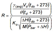
If the value of R is 1.0 ±0.05, the meter correction factor is acceptable for use in the following test series. Otherwise, the meter must be recalibrated before use.
7.0 References
- Environment Canada, Reference Method EPS 1/RM/8, Reference Methods for Source Testing: Measurement of Releases of Particulates from Stationary Sources, December, 1993.
- Ministry of Environment and Energy, Province of Ontario, Source Testing Code, Version 2, Report # ARB-66-80, November 1980.
- United States Environmental Protection Agency, Code of Federal Regulations, Title 40 Part 60, Appendix A, July 1. 1994.
Table 4-1: Field Sampling Report (Example)
Plant*:
Location*:
Date*:
Operators*:
Run No.*:
Pitot Coefficient*: 0.850
Dry Gas Meter (γ) Factor*: 0.991
Initial Leak Check (m3/min):
Final Leak Check (m3/min):
Ambient Temperature (°C): 23
Barometric Pressure (kPa)*: 100.5
Assumed Moisture Content (%):
Static Pressure (mmH2O)*: 10.9
Stack Diameter (m)*: 2.30
Nozzle Diameter (mm): 7.75
Probe Length (m):
Probe Liner:
Gas Stack Molecular Weight (kg/kgmol): 29.66
Schematic of Stack Cross-section
Traverse Number and Direction - 1, N-S
| Sampling Point Number* | Sampling Time (Min.) |
Stack Temp. TS (°C) |
Velocity Head ΔP (mm H2O) |
Orifice Pressure 'Drop ΔH' (cm H2O) |
Dry Gas Meter Reading (Litres) |
Dry Gas Meter Temp. Inlet Tm in (°C) |
Dry Gas Meter Temp. Outlet Tm out (°C) |
Sample Box Temp. (°C) |
Impinger Outlet Temp. (°C) |
Probe Temp. (°C) |
Vacuum mm Hg) |
|---|---|---|---|---|---|---|---|---|---|---|---|
| 1 | 0 | 234 | 1.09 | 3.56 | 000.000 | 19 | 19 | 120 | 18 | 118 | 76 |
| 3 | 236 | 1.09 | 3.56 | 062.90 | 22 | 19 | 120 | 18 | 118 | 76 | |
| 2 | 6 | 236 | 1.09 | 3.56 | 124.90 | 21 | 21 | 120 | 19 | 120 | 76 |
| 9 | 237 | 1.07 | 3.56 | 186.60 | 21 | 21 | 120 | 19 | 117 | 76 | |
| 3 | 12 | 237 | 1.17 | 3.81 | 247.80 | 23 | 22 | 120 | 20 | 125 | 76 |
| 15 | 237 | 1.14 | 3.81 | 312.70 | 24 | 22 | 120 | 19 | 120 | 76 | |
| 4 | 18 | 237 | 1.14 | 3.81 | 377.30 | 24 | 22 | 120 | 19 | 120 | 76 |
| 21 | 237 | 1.19 | 3.81 | 441.90 | 25 | 23 | 120 | 18 | 119 | 76 | |
| 5 | 24 | 237 | 1.02 | 3.05 | 506.50 | 27 | 23 | 120 | 19 | 120 | 76 |
| 27 | 238 | 1.02 | 3.30 | 564.60 | 27 | 24 | 120 | 20 | 118 | 76 | |
| 6 | 30 | 238 | 1.02 | 3.56 | 623.80 | 28 | 24 | 120 | 19 | 119 | 89 |
| 33 | 238 | 1.02 | 3.56 | 685.00 | 28 | 25 | 120 | 19 | 117 | 89 | |
| 7 | 36 | 238 | 1.02 | 3.56 | 745.90 | 28 | 26 | 120 | 20 | 120 | 89 |
| 39 | 238 | 0.99 | 3.43 | 806.80 | 29 | 27 | 120 | 19 | 121 | 89 | |
| 8 | 42 | 238 | 0.94 | 3.30 | 867.10 | 29 | 28 | 120 | 18 | 120 | 89 |
| 45 | 237 | 0.97 | 3.30 | 925.20 | 29 | 28 | 120 | 18 | 122 | 89 | |
| 48 | 983.50 | ||||||||||
| avg. 237 | avg. 1.06 | avg. 3.53 | avg. 26 | avg. 23 |
Table 4-2: Moisture Data (Example)
| Final Weight (g) | Tare Weight (g) | Weight of Moisture (g) | |
|---|---|---|---|
| Impinger #1: | 828.1 | 696.6 | 131.5 |
| Impinger #2: | 447.0 | 436.2 | 10.8 |
| Impinger #3: | 417.7 | 417.5 | 0.2 |
| Impinger #4: | 685.7 | 681.6 | 4.1 |
| Total | 146.6 |
Table 4-3: Field Sampling Report Template
Download Field Sampling Report Template
Figure 4-1: Moisture Sampling Train
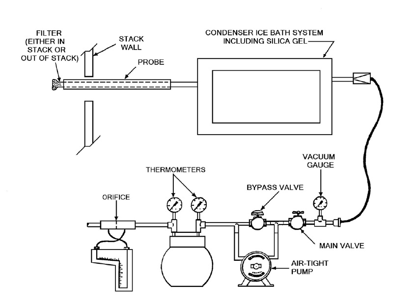
This image illustrates the assembly of a moisture sampling train which is comprised of nine main components. The first component is the probe which is inserted into the sampling port located in the stack wall. The probe includes a filter which may be in the stack or out of the stack. Following the probe is a condenser ice bath system which includes the use of silica gel. This condenser system is connected to a vacuum system. The vacuum system has six parts. The first part is a vacuum gauge followed by a main valve which is connected to a bypass valve. The bypass valve is in parallel with an air-tight pump. The bypass/pump assembly is followed by two thermometers and then an orifice.
Figure 4-2: Midget Impingers Moisture Sampling Train
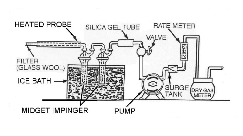
This image illustrates the assembly of a midget impingers moisture sampling train. There are ten parts organized in the following sequence. The first component is the heated probe which is equipped with a filter (glass wool) and inserted into the stack. The gas sample is then passed through two midget impingers which are immersed in an ice bath. Following this cooling step, the sample is passed through a silica gel tube which is connected to a valve that controls the flow of the pump. Following the pump is a surge tank, rate meter and dry gas meter.
Figure 4-3: Assembly for Calibration of Dry Gas Meter
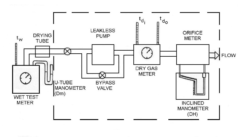
This image depicts the assembly of gas sampling devices for the purpose of calibrating a dry gas meter. The first component is a wet test meter that measures the reference temperature and pressure using a thermometer and u-tube manometer, respectively. The wet test meter is connected to a drying tube; leading to a leakless pump by a direct valve. It is also equipped with a bypass valve. Next is the dry gas meter that includes two thermometers for reference. Finally, the flow passes through orifice meter that measures the pressure using an inclined manometer.