Calibrating airblast sprayers
Learn a simple and effective method for calibrating an airblast sprayer, with clear terminology and reasons for calibrating regularly.
Introduction
Calibration is one of the most important aspects of spray application and yet it remains neglected and misunderstood by most operators. Common reasons for not calibrating are:
- difficulty
- length of time required to calibrate
- confusing terminology
- multiple methods for calibration
- the incorrect belief that calibration has very little impact
This fact sheet describes a simple and effective method for calibrating an airblast sprayer, with clear terminology and equally clear reasons for calibrating regularly.
Defining terminology
"Application rate" is a general term used to describe the amount of material that is placed on a treatment area. Depending on the publication, this term may refer to the total volume of spray mixture, the amount of formulated product or the amount of active ingredient. Therefore, for the purposes of explaining the calibration procedure, the term "Application Rate" will not be used in this fact sheet.
"Sprayer output" describes the total amount of material that is delivered by the sprayer to the treatment area (for example, 500 L/ha). This includes the formulated product as it is supplied from the manufacturer and the carrier used to make up the total spray mixture.
"Product rate" describes the label-recommended amount of formulated pesticide product, as it is supplied by the manufacturer, placed on the treatment area (for example, 1 kg/ha).
Why calibrate?
Calibration is essential because it:
- confirms that the sprayer output is accurate
- ensures that the correct product rate is applied
- reduces product wastage and environmental impact
- confirms that each nozzle is delivering the desired output
That final point is very important. A boom that has both worn and plugged nozzles can still deliver the calculated sprayer output, so every nozzle must be tested. Even brand new nozzles must be tested. It is not unheard of for new nozzles to deviate from the ideal rate by as much as 15%.
When to Calibrate
Product rates and sprayer output requirements change, depending on the crop type, the plant spacing and the crop and pest staging. Therefore, calibrate for each significantly different situation. Calibrate airblast sprayers:
- at the beginning of each season
- mid-way through the each season as crops grow and fill in
- after changes to application equipment or settings (for example, nozzles, operating pressure, pump, tractor or tractor wheels)
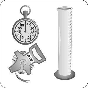
Figure 1. Typical calibration tools, including a stopwatch, a tape measure and a collection vessel of known volume.
Equipment and tools
When calibrating an airblast sprayer, wear coveralls, gloves, boots and possibly a face shield. You will also need (see Figure 1):
- a stopwatch
- a 50-m measuring tape or measuring wheel
- graduated cylinders (large-mouth, 1,000-mL capacity with raised graduations)
- a reliable, spare oil-filled pressure gauge
- lengths of hose to direct output into collection vessel
- a calculator
- two stakes or flags
- a pen and hard-covered notebook
- a proven calibration formula and technique
Where to calibrate
Calibrate sprayers in a vineyard, nursery or orchard that is representative of the vineyard, nursery or orchard to be sprayed. Calibrating a sprayer on a hard surface (such as pavement) can induce errors as high as 15% compared to calibrating in a tilled field. Calibrate away from buildings and wells.
How to calibrate
There is more than one way to calibrate an airblast sprayer. Essentially, every method requires you to determine:
- total spray output of the sprayer
- true ground speed of the sprayer
- product rate
- nozzle output and orientation
Use the checklist below to help with your calibration.
Calibration step-by-step
Perform a pre-calibration inspection
Fill the decontaminated sprayer half-full with clean water and:
- Ensure all hoses and fittings are sound.
- Ensure all screens and nozzles are clean.
- Ensure tire pressure (tractor and sprayer) is correct.
Start the pump and set the tractor engine speed to the desired rpm. Open the manifold valve to fill the lines and begin spraying. Adjust the pressure regulator, or set the main by-pass, to obtain the desired operating pressure. Perform the following steps:
- Check that each nozzle shut-off valve is working.
- Check that the agitation system is functioning properly.
- Search for and correct any leaks.
Adjust the air stream
The air stream created by the sprayer fan carries the spray mixture into the trees or vines and distributes it throughout the foliage. To reach all leaf surfaces and achieve adequate pesticide coverage, all the air around the foliage must be replaced by the spray-laden air stream.
Early-season airblast spraying generally requires very little air, unless competing with wind. Later in the season, larger, fuller canopies require a greater volume of air. In some cases, air volume can be varied by increasing or decreasing the power take-off speed (PTO rpm), engine rpm or the fan gear.
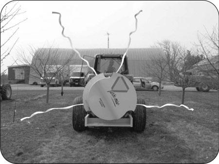
The air direction or angle of attack to the foliage is equally important:
- Tie lengths of ribbon to the nozzle bodies or deflectors and turn on the air (see Figure 2).
- Adjust outlets and/or deflectors to aim air into the canopy, not over or beneath it.
- Shut off upper or lower nozzles to optimize the spray pattern.
Confirm sprayer pressure
To confirm that the main pressure gauge is accurate, temporarily install a second oil-filled gauge in-line beside the main pressure gauge.
Pressure in the booms is often less than the desired operating pressure.
- Install an oil-filled pressure gauge in the last nozzle position of one of the two booms. If necessary, remove the nozzle body for this step. Get fittings to match the thread or nozzle body (see Figure 3 for examples). Use four wraps of plumber's tape to ensure a water-tight connection.
- Turn on the spray and compare boom pressure to desired pressure.
- Adjust the main pressure regulator until the desired boom operating pressure is reached.
Piston-operated sprayers and sprayers equipped with diaphragm pumps generally do not maintain the desired output when spraying from a single boom. Most units will experience a pressure increase, thereby increasing the sprayer output. Some sprayers compensate through an electric bypass valve that shunts extra volume and pressure back to the tank. The rate can be adjusted using a throttling valve to match the volume that would be spraying out through the closed boom. Ideally, the pressure should remain the same when a boom is shut off. To set the bypass:
- Set the desired pressure at the regulator with both booms running.
- Turn off one boom. Note the pressure change.
- If the pressure increased, open the throttling valve at the back of the tank until the pressure is the same as if both booms were running; if the pressure decreased, close the valve to achieve the proper pressure.
Centrifugal pumps generally do not have regulators but do have bypasses that offer limited control over operating pressure.
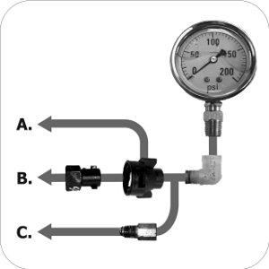
Figure 3. Three methods to attach a pressure gauge to an airblast boom:
A. Use an elbow and a quick-connect cap for sprayers with booms with quick-connect nozzle bodies.
B. Use an elbow, quick-connect cap and quick-connect adapter for male-threaded nozzle bodies such as FMC.
C. Use an elbow and a suppressor to replace an entire nozzle body.
Set forward speed
Forward speed must be slow enough to allow the air stream to completely replace the air in the canopy, but not so slow that excessive blow-through results. Generally, this will be no faster than 5 km/h (~3 mph). Forward speed also impacts the product rate. Measure the time for the sprayer to drive 50 m. This step corrects speedometer errors due to wheel slippage. It is important to perform this step in the field so it accounts for soil type, slope of terrain and the average weight of the sprayer.
- Measure out a distance of 50 m and mark the start and finish positions with stakes or flags.
- Fill the sprayer tank half full of clean water.
- Select the gear and engine speed in which you intend to spray. Be sure that the blower is going, without discharging spray.
- Bring the sprayer up to speed and begin timing as the front wheel passes the first flag.
- Stop the timer as the front wheel passes the second flag.
- Stay out of any ruts and run the course two more times.
- Determine the average time for the three runs (see example).
Calculate forward speed using one of the following formulae, depending on the units used:
Forward speed (km/h) = 50 m x 3.6 / Average drive time in seconds
Forward speed (mph) = 50 m x 2.2 / Average drive time in seconds
Calculate sprayer output for each side
Airblast disc-core, disc-whirl and moulded nozzles are sold based on their output per minute. A set of nozzles on one boom, when added together, should produce the required output per side. Use any of the following formulae, depending on the units used:
- Output per side (US gal/min/side) = (Target sprayer output (US gal/acre) x Forward speed (mph) x Row spacing (ft)) / 1000
- Output per side (L/min/side) = (Target sprayer output (L/acre) x Forward speed (km/h) x Row spacing (m) / 500
- Output per side (L/min/side) = (Target sprayer output (L/ha) x Forward speed (km/h) x Row spacing (m) / 1,220
Select a set of nozzles to produce the required sprayer output at the selected operating pressure. Choose nozzles that both give a correct total output and produce the desired spray pattern.
Based on the results of the ribbon test, place nozzles of different outputs in appropriate locations on the sprayer manifold to achieve the desired spray pattern. Usually, most of the spray volume is directed at the thickest foliage (see Figure 4).
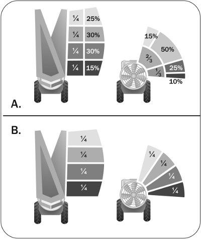
Figure 4. A. Suggested spray distribution for airblast sprayers on classic spindle apple trees. B. If the canopy is of uniform depth, such as with vines, spray distribution should also be uniform, where each nozzle sprays the same rate. Fractions represent the portion of the boom. Percentages represent the relative amount of sprayer output. These distributions may change depending on the location of the pest or when there is fruit to protect.
Confirm spray distribution and air settings by placing water-and-oil-sensitive paper in the hardest-to-reach portions of the canopy, then spraying the entire canopy with clean water. Make corrections to the set-up to achieve adequate coverage throughout the canopy.
As the canopy grows and fills, reconsider the spray distribution and output volume. For example, some apple growers choose to open another nozzle position lower on the boom to hit low-hanging branches, but this is not the best way to redistribute spray. The better approach is to turn on a lower nozzle position, then distribute a higher sprayer output over the entire boom; this way, the whole canopy gets more spray, not just the bottom of the target.
Measuring actual sprayer output
In theory, the sprayer has been set up to deliver a specific output per side. In fact, the output may be different than expected. This is true both of new nozzles, which can vary in output by as much as 15%, and of old ones, which may be worn through use. To calculate the total delivery rate, measure the actual output per minute of each nozzle. Use a diagram similar to Figure 5 to track nozzle rates:
- Position the sprayer on a level location and fill it approximately half full of water.
- Start the sprayer pump. Set the pressure to that used when selecting nozzles.
- Use a length of hose to direct spray from each nozzle into a graduated cylinder or collection vessel for 1 minute.
- Compare the nozzle output to the rated output in the manufacturer's catalogue.
- Replace any nozzles that are 10% more or less than the rated output; 5% is preferable, if possible. If two or more nozzles are worn, replace all nozzles.
- Calculate the total output of one boom and compare to the targeted total output.
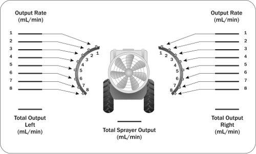
Figure 5. Example of a nozzle output record.
For more information
- Ontario Pesticide Education Program's Grower Pesticide Safety Course Manual
- OMAFRA Publication 360, Guide to Fruit Production
Pre-calibration checklist
Pre-calibration inspection
Pump and lines
- valves, diaphragms and/or plungers checked/replaced
- all hoses and fittings sound
- pump flushed and spray discharge clear
- pump lubricated
Strainers and nozzles
- all strainers from tank opening to nozzle strainers clean and unbroken
- all nozzles clean and unbroken
- each nozzle shut-off working
Regulators and gauges
- all gauges true
- regulator(s) and/or bypass valve(s) move easily
Belts and Power Take-Off (PTO)
- all belts have proper tension and no wear
- PTO greased, connection zones checked and guard in place
Propeller and agitation
- propeller has no nicks or cracks or residue and does not have any lateral play
- jets oriented to scrub bottom of tank or propellers secure, shaft greased and packing tight (no leaks)
Orientation and adjustment
Airflow and direction
- volutes or deflectors adjusted to steer air into canopy
- air reduced in early season through lower RPMs and low gear
- ribbons used to determine which nozzles should be active
Spray pressure adjustment
- sprayer pressure set to desired pressure
- each boom operating at desired pressure
Metric/imperial conversions
- 1.0 L=0.264 US gal (most common in catalogues)
- 1.0 L=0.22 Imperial gal
- 1.0 m=39.4 in.
- 1.0 ha=2.47 acres
- 1.0 km/h=0.62 mph
- 1.0 L/ha=0.106 US gal/acre
- 1.0 L/ha=0.09 Imperial gal/acre
This fact sheet was authored by Dr. Jason S.T. Deveau, Application Technology Specialist, OMAFRA, Simcoe, and reviewed by Helmut Spieser, Engineer, Field Crop Conditioning and Environment, OMAFRA, Ridgetown.