Compliance protocol for wind turbine noise
This guide is for assessing noise from wind turbines that have already been built. It is used by industry and ministry staff to monitor compliance.
Published: April 2017
The Ministry of the Environment and Climate Change (MOECC) is committed to ensuring that its policies and protocols regarding wind farms continue to reflect current science. Should new information come to light, the MOECC will review and amend its policies and protocols as required.
All requirements relating to Renewable Energy Approval (REA) applications and renewable energy projects are contained in Part V.0.1 of the Environmental Protection Act and O. Reg. 359/09, which can be found at Ontario’s e-Laws website or the official volumes printed by Publications Ontario for the authoritative text. Specific references to the Noise Guidelines for Wind Farms, Reference [4] as amended, are made throughout this protocol and readers are recommended to have access to a copy of the guideline itself to refer to the exact language when reading.
Ministry of the Environment and Climate Change
Public Information Centre:
E-mail: picemail.moe@ontario.ca
Website: Ministry of the Environment and Climate Change
Part A: General
A1 References
The following publications are referenced in this document:
- CAN/CSA-C61400-11-07, "Wind Turbine Generator Systems – Part 11: Acoustic Noise Measurement Techniques"
- ISO 1996-2, "Acoustics – Description, assessment and measurement of environmental noise – Part 2: Determination of environmental noise levels"
- ISO 9613-2, Acoustics – Attenuation of sound During Propagation Outdoors, Part 2: General Method of Calculation
- Noise Guidelines for Wind Farms – Interpretation for Applying MOECC NPC Publications to Wind Power Generating Facilities May 2016; PIBS number 9900e
- "Compliance Policy Applying Abatement and Enforcement Tools", May 2007, PIBS #6248, Ontario Ministry of the Environment, as amended
- CAN/CSA-IEC 61400-11:13, "Wind Turbines – Part 11: Acoustic Noise Measurement Techniques", Canadian Standards Association
- IEC 61672-1 (2002), "Electroacoustics – Sound level Meters, Part 1" Specifications
- IEC 60942: 2003, "Electroacoustics – Sound Calibrators"
A2 Definitions
For the purposes of this document, the following definitions apply:
- "Abatement"
- means voluntary or mandatory actions taken to achieve compliance.
- "Acoustic Assessment Report" or "Noise Assessment Report"
- means the report submitted in support of the Approval (and usually referenced in the Approval) that demonstrates through acoustic modelling the subject wind facility is in compliance with the applicable noise limits defined in the Noise Guidelines for Wind Farms, Reference [4].
- "Acoustic Audits"
- means E-Audits and/or I-Audits.
- "Acoustic Audit – Emission (E-Audit)"
-
means an investigative procedure that is compliant with:
- the Standard CAN/CSA-C61400-11-07, Reference [1], or
- the CAN/CSA-IEC 61400-11:13, Reference [6], or
- at the Director’s discretion, compliant with another equivalent standard.
It consists of measurements in close proximity to wind turbines. The E-Audit is used to determine compliance with the manufacturer’s acoustic equipment specifications and emission data for wind turbines included in the Acoustic Assessment Report.
- "Ambient sound level"
- means background sound level.
- "Approval"
- means a Certificate of Approval issued under section 9 of the Environmental Protection Act (EPA), a Renewable Energy Approval (REA) issued under section 47.5 of the EPA, or an Environmental Compliance Approval (ECA) issued under Part II.1 of the EPA.
- "A-weighting"
- means the frequency weighting characteristic as specified in the International Electrotechnical Commission (IEC) Standard 61672, Reference [7], and intended to approximate the relative sensitivity of the normal human ear to different frequencies (pitches) of sound. It is denoted as "A".
- "A-weighted sound pressure level"
- means the sound Pressure Level modified by application of an A-weighting network. It is measured in decibels, A-weighted, and denoted "dBA".
- "background sound level"
- means the sound level that is present in the environment, produced by noise sources other than the source under impact assessment. The background sound level is typically caused by sounds from nature for Receptors removed from urban areas, or by road traffic for Receptors in urban/suburban areas. Highly intrusive short duration noise caused by a source such as an aircraft fly-over or a train pass-by (including light rail transit, subways and streetcars) is normally excluded from the determination of the background sound level.
- "Binning"
-
with respect to Reference [1], I–Audits and RAM I-Audits, binning means the processing of measured sound level data by arranging the accumulated data in "bins" representing integer wind speeds, ±0.5 metres/second (m/s). Each "bin" is centered on the integer wind speed and spans 1 m/s. Open at the low end and closed at the high end. For example, the 7 m/s bin ranges from 6.50 m/s to 7.49 m/s (inclusive).
With respect to Reference [6], binning means the processing of measured sound level data by arranging the accumulated data in "bins" representing half-integer wind speeds, ±0.25 metres/second (m/s). Each "bin" is centered on the integer or half-integer wind speed and spans 0.5 m/s. Open at the low end and closed at the high end. For example, the 12 m/s bin ranges from 11.750 m/s to 12.249 m/s (inclusive).
Once binned, the mean (logarithmic average) of the Leq is computed for each wind speed bin.
- "Class 1 Area"
- means an area with an acoustical environment typical of a major population centre, where the background sound level is dominated by the activities of people, usually road traffic, often referred to as "urban hum".
- "Class 2 Area"
- means an area with an acoustical environment that has qualities representative of both Class 1 and Class 3 Areas:
- sound levels characteristic of Class 1 during daytime (07:00 to 19:00 or to 23:00 hours);
- low evening and night background sound level defined by natural environment and infrequent human activity starting as early as 19:00 hours (19:00 or 23:00 to 07:00 hours).
- "Class 3 Area"
- means a rural area with an acoustical environment that is dominated by natural sounds having little or no road traffic, such as the following:
- a small community with less than 1,000 population;
- agricultural area;
- a rural recreational area such as a cottage or a resort area; or
- a wilderness area.
- "Complete E-Audit"
-
means an audit report for a wind turbine based on the measurement protocol defined in:
- Reference [1], and conducted at the standardized wind speeds of 6, 7, 8, 9 and 10 m/s (10 m height), or
- Reference [6] or
- at the Director’s discretion, compliant with another equivalent standard.
As noted in References [1] and [6],
measurements of sound pressure levels and wind speeds are to be made simultaneously over
.short periods of time
(i.e. six weeks or approximately one season) - "Complete I-Audit"
- means an audit report for a wind facility that for each wind speed bin between four (4) and seven (7) m/s (inclusive), there is sufficient one (1) minute equivalent sound level data (Leq). Specifically, 120 data points for measurements when the turbines are operational and 60 data points for ambient measurements when the turbines are parked.
- "dBA"
- means the A-weighted sound pressure level.
- "Decibel"
- means a dimensionless measure of sound Level or sound Pressure Level, denoted as dB.
- "Director"
- means a person appointed by the Minister of the Environment and Climate Change pursuant to section 5 of the Environmental Protection Act (EPA) as a Director for the purposes of section 47.5 of the EPA.
- "District Manager"
- means the District Manager of the appropriate local district office of the Ministry where the wind facility is geographically located.
- "equivalent sound level, Leq (T)"
- means the A-weighted sound pressure level of a steady sound carrying the same total energy in the time period T as the observed fluctuating sound. The time period T is usually stated in hours. Leq without a specific time period means one hour Leq (1).
- "exclusion limit"
- means the lowest value of the sound level limit at a specific point of reception for the stationary source, i.e., the sound level limit when the background sound level is below this exclusion limit. For example, 40 dBA at 6 m/s (10m height).
- "Ministry"
- means the Ministry of the government of Ontario responsible for the EPA and includes all officials, employees or other persons acting on its behalf.
- "Noise Abatement Action Plan" or "NAAP"
- means the noise Abatement program developed by the owner/operator of the wind facility to achieve compliance with the sound level limits set out in section D6 of this document. The Abatement program must be reviewed and approved by the Ministry before it is incorporated into the wind facility.
- "Noise"
- means unwanted sound.
- "Non-compliance"
- is a state achieved when a person, who is bound by legal provision(s), does not act in accordance with the legal provision(s).
- "Participating receptor"
- has the same meaning as in the Noise Guidelines for Wind Farms and is subject to the same qualifications described in that document, Reference [4].
- "Point of reception"
- has the same meaning as in the Noise Guidelines for Wind Farms and is subject to the same qualifications described in that document, Reference [4], and must be listed in the Acoustic Assessment Report referenced in the Approval.
- "Qualified acoustical practitioner" or "Practitioner"
-
means a person trained and currently active in the field of environmental acoustics and noise/vibration control who is familiar with Ministry procedures and has a combination of formal university education, training and experience necessary to perform the wind turbine noise measurements. It is recommended that the Qualified acoustical practitioner be a Professional Engineer.
Through the Professional Engineers Act, Professional Engineers Ontario (PEO) governs licenses and certificate holders and regulates professional engineering in Ontario. PEO defines professional engineering to be:
- any act of planning, designing, composing, evaluating, advising, reporting, directing or supervising (or the managing of any such act);
- that requires the application of engineering principles; and
- concerns the safeguarding of life, health, property, economic interests, the public welfare or the environment, or the managing of any such act.
In Ontario, only those individuals who have demonstrated that they possess the necessary qualifications and have been licensed by PEO can use the title Professional Engineer, which is often abbreviated as "P.Eng."
- "RAM I–Audit"
-
means a Revised Assessment Methodology (RAM) for I-Audits conducted in accordance with section E5.5 of this document. Significant provisions of this methodology are as follows:
- requires downwind assessment between the closest turbines(s) and the assessment location;
- requires the closest turbine(s) to be operating at or within approximately 90% of its maximum sound power level;
- expands the measurement wind bins from four (4) (4 to 7 m/s) to seven (7) bins (1 to 7 m/s); and
- allows the assessment/analysis to be based on fewer measurements.
- "receptor"
- means a point of reception, or when applicable (refer to Appendix F3), a Participating receptor or an alternate measurement location used as part of an I–Audit.
- "setback"
- means the horizontal distance (plan-view) in metres separating the wind turbine coordinates and the coordinates of a receptor.
- "sound level"
- means the A-weighted sound pressure level.
- "sound level limit"
- means the limiting value described in terms of the one hour equivalent sound level, Leq. For example, 40 dBA at 6 m/s (10 m height).
- "sound power level" or "Lw"
- means the rating that, is given to a wind turbine by the manufacturer of the wind turbine, calculated in accordance with standard CAN/CSA-C61400-11, "Wind Turbine Generator Systems – Part 11: Acoustic Noise Measurement Techniques". In this document, the level may also refer to the value associated with a wind turbine at its origin, (fixed/stationary location).
- "sound pressure"
- means the instantaneous difference between the actual pressure and the average or barometric pressure at a given location. The unit of measurement is the micro Pascal (µPa).
- "sound pressure level"
-
means twenty times the logarithm to the base 10 of the ratio of the effective pressure (µPa) of a sound to the reference pressure of 20 µPa.
It is a value associated with a distance from a stationary noise source (wind turbine or transformer substation). In this document, the value may also refer to the sound received from a wind turbine at a measurement location.
- "tonality"
- means a pronounced audible tonal quality of the sound such as a whine, screech, buzz or hum.
- "urban hum"
- means aggregate sound of many unidentifiable noise sources due to the activities of people and primarily composed of road traffic related sound sources.
- "Wind Rose"
- means a diagram showing the wind directions and wind speed class (range of wind speeds) encountered at a measurement location during a measurement interval of interest. Using apolar coordinate system of gridding, the frequency of winds over a time period is plotted by wind direction, with color bands showing wind speed ranges. The direction of the longest spoke shows the wind direction with the greatest frequency (prevailing wind direction). Wind roses typically use 16 cardinal directions, such as north (N), NNE, NE, etc.
A3 Purpose
The document is comprised of the following five parts:
- Part A provides a general overview, including the definitions and references used in this document.
- Part B provides guidance to Ministry staff when investigating complaints concerning noise due to the operation of a wind turbine or a wind facility. The intent is to provide Ministry staff with the technical tools to determine if the noise complaints require additional investigation in the form of acoustic screening measurements as detailed in Part C of this document.
- Part C provides guidance to Ministry staff and/or Qualified acoustic practitioners to perform acoustic screening measurements to determine if a complaint warrants a detailed acoustic audit (I-Audit) as detailed in Part D of this document.
- Part D provides guidance to Qualified acoustic practitioners that undertake detailed Acoustic Audits or complaint investigations of wind facilities (I-Audits). This part of the document will be used to confirm compliance with Ministry sound level limits in section D6 of this document.
- Part E provides direction to Qualified acoustic practitioners when assessing the results of E-Audits and I-Audits against the applicable sound level limits. The guidance will allow Qualified acoustic practitioners to determine if the measured values are acceptable.
A4 Scope
The scope of the document aims to encompass the pertinent aspects of noise complaints, Approval audits and compliance assessments resulting from the operation of wind facilities. This involves a range of issues including turbine locations and distances, compliance with conditions of Approvals, screening of complaints and detailed measurements of the wind facilities sound levels.
The procedures included in this document primarily relate to large modern commercial/industrial wind facilities with rated electrical power in the megawatt (MW) range (i.e. Class 4 wind turbines as classified under Ontario Regulation 359/09), and the focus is mainly on Receptors in Class 3 areas. However; some of the information may also be applicable to smaller wind turbines, namely Class 2 and 3 wind turbines (as classified under Ontario Regulation 359/09), and the installation of wind facilities in urban areas.
Sound from wind turbines that satisfy the applicable sound level limits may be audible and result in complaints. This document will address complaints of this nature. However, wind turbine noise in the infrasound range or ultrasound ranges (i.e. outside the normal audio range; less than 20 hertz or greater than 20,000 hertz), transformer substation noise, and other issues such as shadow flicker or health effects are beyond the scope of this document.
A4.1 Qualitative screening process (Part B of this document)
The initial screening is a qualitative assessment to focus on compliance issues related to conditions and parameters used in the Approval process.
Based on the results from the qualitative screening, a decision can be made whether to perform a quantitative screening (Part C of this document), or carry out detailed acoustic measurements (Part D of this document), at the site of the complainant. In some cases, based on any screening result in this protocol, the wind facility operator may decide to voluntarily undertake actions to reduce the noise impact.
A4.2 Quantitative screening process (Part C of this document)
The quantitative screening involves short-term attended acoustic measurements and/or acoustic recording at a receptor to determine if detailed acoustic measurement(s) is required to assess compliance with noise limits in Reference [4].
A4.3 Detailed acoustic measurements (Part D of this document)
The detailed acoustic measurement procedure is intended to determine the sound levels produced by the operation of a wind facility at a receptor/measurement location, at all applicable wind speeds, to assess compliance with the Ministry’s sound level limits.
A4.4 Compliance evaluation and transition rules (Part E of this document)
A4.4.1 Compliance evaluation
Part E of this document addresses how the Ministry will review E-Audits and I-Audits and what steps (options) an owner / operator of a wind facility can take to address audits that are incomplete
Part E also outlines how the Ministry plans to verify and address compliance with the applicable sound level limits.
A4.4.2 Transition rules for I-Audits
This document replaces the previously applicable document, "Compliance Protocol for Wind Turbine Noise, Guideline for Acoustic Assessment and Measurement", January 2011. All Approvals, regardless of when they were issued, which include conditions requiring owners/operators of wind facilities to carry out two I-Audits in accordance with Part D of the Compliance Protocol, are now subject to Part D of this document.
However, for I-Audits submitted to the Ministry before the date on this document, the revised data filtering requirements in Part D, such as, but not limited to, the downwind data and the 85% power output of the closest wind turbine, do not apply. Any I-Audits submitted to the Ministry after the date on this document will be subject to all of the requirements in Part D of this document.
In addition, Part D of this document contains the following two options for carrying out an I-Audit:
- a standard I–Audit
- a revised assessment methodology (RAM) I–Audit
If incomplete I–Audits are submitted to the Ministry, Part E of this document contains the following three options for owners / operators of wind facilities to choose from to remedy the incomplete I-Audits:
- supplement the I-Audits with existing data and reassess using this document
- combine the two I-Audit measurements
footnote 3 and then conduct an additional I-Audit using this document - conduct two new I-Audits using this document
A4.4.3 Acceptable standards for E-Audits
Irrespective of the date on this document, any E-Audit required by an Approval or complaint investigation can be conducted in accordance with either of the following publications:
- Reference [1], CAN/CSA-C61400-11-07, "Wind Turbine Generator Systems – Part 11: Acoustic Noise Measurement Techniques"
- Reference [6], CAN/CSA-IEC 61400-11:13, "Wind Turbines – Part 11: Acoustic Noise Measurement Techniques", Canadian Standards Association
A5 Background sound levels
Unlike most industrial or commercial noise sources, the sound immissions from wind turbines occur during wind conditions that typically induce significant levels of background noise due to the wind itself.
The background sound levels during conditions when the wind turbines are in operation near their rated generating capacity are comparable to the sound levels emitted by the wind turbines themselves. Consequently, determination of compliance is challenging and it is necessary to have an accurate account of the contribution from each source (wind and wind facility). An additional challenge is that conventional acoustic instrumentation, normally used for the measurement of industrial noise sources, is prone to produce erroneous signals due to the interaction of wind blowing over the microphone (including a windscreen), particularly at winds speeds at 4 m/s and higher.
Consequently, in order to accurately measure the sound levels due to wind turbines alone, a specialized technique is necessary (described in Part D of this document).
Part B: Complaint assessment – qualitative screening
B1 Purpose
The qualitative screening is the initial step in the assessment of a noise complaint regarding a wind turbine or wind facility. It does not require detailed calculations or sophisticated measurements and uses conservative assumptions regarding the noise impact of a wind facility.
The qualitative screening assists in evaluating the complaint with respect to specific parameters used in the Approval. Following this initial screening, and if required, further quantitative screening may be performed.
B2 Qualitative screening
The following steps are recommended to be performed in sequence but can also be performed in parallel.
B2.1 Step 1 – initial screening
Determine the current setback from the receptor to the closest wind turbine. A receptor located within 1,500 m of a wind turbine may be considered to be potentially in a noise area ranging from about 30 dBA and greater depending on the distance and number of turbines (within approximately 3 kilometers (km) of the receptor). Outside of this 1,500 m distance any detectable sound levels from land based wind turbines will not exceed the Ministry’s sound level limits.
Therefore, further noise assessment would not be practical or necessary and this should be communicated to the complainant. However, the owner/operator of the wind facility will be required to verify that all wind turbines (and if applicable, transformers) within the facility are operating:
- within the manufacturer’s performance parameters (i.e. there are no maintenance issues)
- in the correct mode (not a de-rated mode)
- with the correct firmware (correct pitch of blades and torque of turbine)
Alternatively, if the closest wind turbine is within 1,500 m of the subject receptor then proceed to Step 2 (section B 2.2).
B2.2 Step 2 – site visit and interview
If the closest wind turbine is within 1,500 m, then obtain a full description of the nature of the complaint including specific details about the noise from the complainant. The purpose of obtaining the description is to identify from the complainant specific details about the noise issue that would assist in determining further action. A set of open-ended questions are included in the sample form in Part F (section F1) of this document.
The purpose of the site visit and interview is to identify noise sources and features that will have an impact on the background noise and possibly on acoustic measurements. Take note from site observations of any other noise sources within the complainant’s property and in the immediate vicinity (i.e. dryers, coolers, fans, generators, etc.). Also, take note of any unusual features such as trees, shrubbery, water features, hills, ancillary buildings, etc.
Examine the wind facility to ensure that the constructed facility is consistent with the Approval. For example, observe whether the blades of the wind turbines were modified during the project installation by the addition of vortex generators, dyno-tails, etc., such that the aerodynamics of the blades are no longer consistent with the Approval.
Determine the actual setback distance between the subject receptor and the closest wind turbine(s) and proceed to Step 3 (section B 2.3)
B2.3 Step 3 – check for setback reductions
Verify the locations of all wind turbines up to 1,500 m surrounding the property of the complaint site in order to determine if there has been a change in the layout of the wind facility relative to the layout that was approved.
Any significant discrepancies with respect to the Approval will require the owner/operator of the subject wind facility to apply for an amendment to the Approval, and may result in Abatement or enforcement action if warranted.
If it is found that the discrepancy in some wind turbine locations (within the 1,500 m radius) resulted in Setbacks from the complaint receptor reduced by more than 4% (tolerance value) from the approved layout, then the discrepancy will be considered as a major project design change. If the Approval specifies a lower tolerance value, (i.e. 2% or 10 m), this value is applicable in the distance setback reduction assessment.
Technically, a reduction in setback due to the closest wind turbine of 4% can result in an increase in sound level at the receptor of 0.35 dB. Although such an increase is not perceptible, it may result in an excess over the sound level limit at that location.
In this case, the assessment needs to be verified using the as-built layout affecting the complainant’s location and using the prediction model specified in the Approval. Specifically, the parameters to be used must reflect the worst-case noise impact by assuming the maximum acoustic immissions from the turbines against the lowest applicable sound level limit.
If the modelling calculations determine a level greater than the sound level limit, the owner/operator of the wind facility may be required to implement appropriate noise Abatement measures to achieve compliance with the sound level limits or follow the guidance in Part E of this document. However; further assessment may not be required if the owner/operator of the wind turbine is prepared to voluntarily reduce the sound levels.
If the reductions of setback distances are not greater than 4% then proceed to Step 4 (section B2.4). If the Approval specifies a lower tolerance value, (i.e. 2% or 10 m), this value is applicable in the distance setback reduction assessment.
Refer to Part F (section F2) of this document for a summary of the procedure and a partial sample assessment.
B2.4 Step 4 – check predicted noise impact
Check the calculated sound level corresponding to the receptor included in the Acoustic Assessment Report for the wind facility. If the results indicate compliance within a margin of at least 5 dB below the limit (i.e. 35 dBA or lower), further assessment at this site would be at the discretion of Ministry staff.
However; if the predicted level is less than 5 dB from the limit (i.e. above 35 dBA), then further assessment at the complaint location would be warranted. Proceed to Part C of this document or, alternatively, in the case of a significant oversight and in agreement with the owner/operator of the wind facility, Part D of this document.
Part C: Complaint assessment – quantitative screening
C1 Purpose
The quantitative screening process was designed to provide additional information to that obtained in the initial qualitative screening process. The quantitative screening involves use of instrumentation to obtain sound measurements.
The purpose of the quantitative screening process is to determine the need for further action in evaluating the complaint resulting from wind turbine or wind facility noise. Detailed long-term acoustic measurements at the site of the complainant may be appropriate as a result of the quantitative screening. This process is also applicable to owners/operators of wind facilities that are required to submit an E and/or I-Audit as a condition of Approval or by any other instrument under Ministry legislation. Valid complaints may be investigated, even if the subject facilities have demonstrated, or are required to demonstrate, compliance via an E and/or I-Audit.
In the case of several significantdetailed acoustic audit
to be completed for Ministry district staff to determine, in agreement with the owner/operator of the facility, that non-compliance is occurring.
The excess must only represent the wind facility’s sound levels, not the total noise, (i.e. the background sound level must be logarithmically subtracted from the measurements).
C2 Attended screening measurements
The measurement of sound levels at Points of Reception located at significant distances from the turbines require special instrumentation, specific testing conditions, and careful analysis of the data.
The objective is to determine the wind turbine’s or wind facility’s noise impact at a point of reception expressed as an equivalent sound level. It is recommended that the attended screening measurements be carried out at times when the background sound level is very low. To the extent possible, the measurements should be performed at times when wind turbines operate near their maximum output (maximum rotational speed) while wind speeds at ground elevation (height of 4.5 m or less) are low, optimally not exceeding 3 m/s with a 4 m/s maximum.
C2.1 sound level measuring instrumentation
The sound level measuring instrumentation consists of the following:
- Integrating sound level meter
- Acoustic calibrator
- Wind screen and cables
The sound level measuring instrumentation must meet the following requirements:
- sound level meter specifications according to the IEC 61672-1 (2002), "Electroacoustics – sound level Meters, Part 1": Specifications, Reference [7].
- Class 1 or Class 2 microphone systems. Should a Class 2 rather than a Class 1 microphone system be used, it is recommended that the noise floor of the microphone is at least 25 dBA.
- The instrumentation should have a constant frequency response between 20 Hz to 20,000 Hz.
C2.2 Acoustic calibrator
The complete sound measurement system, including any recording, data logging or computing systems, shall be calibrated immediately before and after the measurement session at one or more frequencies using an acoustic calibrator on the microphone.
The acoustic calibrator shall have an accuracy equal to or better than ±0.3 dB and fulfill the requirements of Class 1 according to IEC 60942:2003, Reference [8], in the temperature range where it is used.
C2.3 Anemometer
The anemometer shall have accuracy equal to or better than ±0.5 m/s and an output resolution of 0.2 m/s or less.
C2.4 Measurement procedure
C2.4.1 receptor location
Measurements for the purposes of complaint assessment should be performed at a point of reception. It should be noted that a measurement location at a two-storey building will be closer to the wind turbine than the modeled location which is at the centre of dwelling.
C2.4.2 Time of measurements
The noise measurements associated with the complaint assessment should be mindful of the complaint character. In addition, the measurements should consider predictable worst case parameters such as high wind shear and the downwind conditions from the closest wind turbine to the measurement location. It is recommended that the measurements be performed during lowest background noise conditions. This period of time is normally in the late evening or nighttime.
C2.4.3 Microphone height
The measurement position at a given receptor is outside the identified receptor dwelling. Preferably, the measurement height should be consistent with the receptor height modelled for Approval purposes.
C2.4.4 Microphone position
Appropriate judgment is expected to be used when positioning the microphone. Some general guidance is given below:
- The microphone position shall be sufficiently away from any large reflecting surfaces (minimum of 5 m recommended). This requirement does not apply if using a small vertical reflecting board attached to the building façade.
- The microphone should be located at a point near the receptor dwelling that is not shielded from the closest wind turbine noise (or wind facility). Wherever possible, the microphone should not be located near deciduous trees or foliage that may affect the noise.
C2.4.5 Anemometer location
The anemometer location (to measure wind speed) should be in the vicinity of the noise measurement location (within 15 m). Wherever possible, the measurement position should represent an area where the wind is not shielded by nearby buildings or objects.
The wind speed measurement should also be performed at the microphone height to comply with the maximum wind speed requirement specified in section C2.4.6.
Wind speed measurements should be carried out at the same time as the noise measurements.
C2.4.6 Acoustic measurements
The objective of the acoustic measurements is to determine the overall equivalent sound level Leq when the turbines are operational under the following conditions:
- The optimum range of wind speeds at the microphone location is up to 3 m/s
- The maximum wind speed at the microphone location does not exceed 4 m/s
C2.4.7 Extraneous noise sources
Measurements are to be inhibited when the sound level is affected by noise from extraneous sources such as vehicle noise, dogs barking and wind gusts (i.e. other than wind turbine sound).
The same result can also be achieved by digitally recording the sound level time history and later editing out the extraneous events and recalculating the descriptors such as Leq. This should address measurement situations where extraneous sounds were not inhibited.
C2.4.8 Duration of measurement
Noise measurements must be performed over a minimum period of one hour. The actual accumulated time of the measured Leq needs to be at least 20 minutes. This should represent the worst case equivalent sound level Leq during the one hour period, following the inhibition of the measurements due to extraneous sources.
C2.4.9 Tonality (tonal assessment)
If a tone is clearly audible and continuous, a 5 dB tonal adjustment should be applied to the measured sound level.
C2.4.10 background sound level
This procedure will require the background sound level to be logarithmically subtracted from the overall equivalent sound level Leq and therefore, will require a separate measurement of the background sound level. Note that the background sound level does not include the contribution from the wind turbine noise.
Where appropriate, the background sound level should be measured using the same instrumentation and for the same duration as the overall sound level described in this section.
C2.5 Documentation
The following information should be reported:
- Conditions during the measurement, including but not limited to:
- time and dates of the measurement
- temperature and humidity
- general weather conditions
- range of wind speeds encountered
- wind direction
- confirmation that the wind turbines were operating (i.e. rotational speed of the closest wind turbine)
- Statement noting whether or not Tonality was observed (qualitative assessment)
- Results of measurements in terms of the equivalent sound level Leq.
- Diagram and pictures showing the location of instrumentation, location of buildings and other local features, and the location of wind turbines.
C2.6 Compliance with limits
The Leq results of the attended measurements obtained during this screening process should be compared with the applicable limits contained in Reference [4] and given in the table below:
| Standardized Wind Speed at 10 m Height, m/s | sound Level Limit dBA |
|---|---|
| < 4 | 40.0 |
| 5 | 40.0 |
| 6 | 40.0 |
| 7 | 43.0 |
| 8 | 45.0 |
| 9 | 49.0 |
| 10 | 51.0 |
C3 Acoustic recording by resident/complainant
As mentioned earlier in section C1, the following procedure is a screening tool used to determine if a detailed acoustic audit as per Part D of this document is required. This procedure should indicate the potential for compliance or non-compliance at times when the resident/complainant finds the operation of a wind facility to be objectionable and when Ministry staff cannot attend the site.
If a Part C3 measurement is completed and the MOECC requires the owner / operator to complete a detailed acoustic audit outlined in Part D, upon request the MOECC may share the Part C3 report with the owner/operator.
C3.1 Scope
The method of measurement described in this section provides information on instrumentation requirement, measurement procedure, data analysis and documentation related to the measurement and recording of the wind turbine or wind facility noise initiated by the resident of the home where the complaint originated. The resident will only trigger the measurement cycle (10 minutes of measurements). The resident will not be involved in any aspect of the equipment setup, calibration or data retrieval and analysis.
The measurement and analysis procedure applies to sound in the audible frequency range, (20 Hz to 20,000 Hz), and includes the measurement of the equivalent sound level, Leq, at a receptor.
C3.2 Overview
A resident via a sound level meter (and/or an audio recording device) securely locked in a tamper proof case with an external trigger, initiates this acoustic screening measurement. Ministry staff or a Qualified Practitioner will set up and calibrate the instrumentation. The approach may be utilized when it is not possible for Ministry staff to make attended observations or measurements at a resident’s home during periods when a resident deems wind turbine or wind facility noise disturbing.
The procedure involves installing a sound recording system/device at a resident’s home to collect a minimum of twelve (12) high quality, 10 minute sound recordings of the offending noise at the exact time of the occurrence (refer to section C3.4.8 for more details regarding recording intervals).
The recording equipment must have the capability of being activated by a resident at any time from inside the resident’s home. It must automatically perform a recording of set duration (10 minutes), and store the audio recording along with the date and time of the recording. The recordings will be analyzed off site.
The off-site analysis will also require operational information of the wind facility such as turbine power output, wind speed, rotation speed of rotor/blades and wind direction at the time of the analysis. In addition, it will require details of atmospheric conditions at the resident’s home.
If the analysis, which includes background sound levels subtracted from the measured sound levels or portions of the measured sound levels that only include the wind facility, indicates that wind turbine noise is audible and that the majority of the 10 minute Leq s indicates that the wind facility sound levels exceed the applicable limits, additional assessment would be warranted. This additional work may consist of one or combination of the following:
- Additional C 3 acoustic recordings at the resident’s location;
- Attended screening measurements in accordance with section C2; or
- Detailed acoustic measurements in accordance with Part D of this document.
C3.3 Instrumentation
C3.3.1 Acoustic instrumentation
The instrumentation is intended for short-term noise measurements, typically seven to eight uninterrupted consecutive days. The recording device can be comprised of either a digital recorder or a sound level meter capable of recording sound files and Leq s simultaneously. The minimum requirements of both devices and the peripheral equipment are noted below:
Minimum requirements of the digital recorder and sound level meter
- Class 1 or Class 2 microphone systems.
footnote 5 It is noted that the Class 2 microphone may not strictly meet the requirements outlined in this section; however, the appropriateness of Class 2 microphones was demonstrated to the Ministry previously during field-testing. If Class 2 microphone systems are used, caution is advised to ensure that:- Noise floor of the microphones is below 25 dBA
- The frequency range is suitable between at least 20 Hz to 8,000 Hz, where the microphone response is effectively flat
- Ability to be triggered by a resident inside the residence.
- The instrumentation must have a constant frequency response over 20 Hz to 20,000 Hz.
- The filters meeting the requirements of IEC 61260 for Class 1 filters.
- Ability to record a 10 minute digital audio waveform file ("wav file"
footnote 6 or equivalent non compressed digital formats at a sampling rate of at least 8,000 Hz. Depending on the composition of the background sound levels, larger sampling rates (i.e. 44,000 Hz) may be required. The minimum sampling resolution should be at least 16 bit. The Ministry at its discretion may require the submission of the original and/or edited recordings. - In addition to the requirements above, appropriate software is also required to:
- determine the 10 minute Leq from the 10 minute sample
- analyze the files in 1/3rd octaves
C3.3.2 Narrowband spectra determination (both devices)
This equipment shall fulfill the relevant requirements for IEC 61672-1(2002), Reference [7], over the frequency range of 20 Hz to 20,000 Hz.
C3.3.3 Acoustic calibrator
The complete sound measurement system, including any recording, data logging or computing systems, shall be calibrated immediately before and after the measurement session at one or more frequencies using an acoustic calibrator on the microphone.
The acoustic calibrator shall have an accuracy equal to or better than ±0.3dB and fulfill the requirements of Class 1 according to IEC 60942:2003, Reference [8], and shall be used within its specified environmental conditions.
C3.3.4 Wind screens
For the measurement of wind turbine sound immission, a primary windscreen must be used. It is recommended that the primary windscreen consist of open cell foam with a diameter of approximately 90 mm centered on the diaphragm of the microphone. It is further recommended that a larger diameter secondary wind screen (approximately 450 mm) be used to reduce the noise from wind blowing over the microphone.
The specifications of the secondary wind screen are indicated in CAN/CSA-C61400-11-07, Reference [1] and CAN/CSA-IEC 61400-11:13 Reference [6] as follows:
…could, consist of a wire frame of approximate spherical shape, at least 450 mm in diameter, covered with a 13 mm to 25 mm layer of open cell foam with a porosity of 4 to 8 pores per 10 mm. This secondary spherical windscreen shall be placed symmetrically over the smaller primary windscreen.
C3.3.5 Anemometer
The anemometer and its signal processing equipment shall have a maximum deviation from the calibration value of ±0.5 m/s in the wind speed range from 0 m/s to 12 m/s. The anemometer itself shall have an accuracy equal to or better than ±0.3 m/s at 10 m/s and an output resolution of 0.2 m/s or less. Wind direction should be measured within 3 degrees. The data should be averaged over at least a 10-minute period.
C3.3.6 Calibration
The sound level meter and calibrator must have a valid calibration certificate traceable to a qualified laboratory. The maximum time from the last calibration shall be as stated by the manufacturer. If a maximum time is not stated, a time period of one year shall be assumed.
C3.3.7 Tamper proof case
The device shall be secured within a tamper proof case, preferably within the resident’s dwelling. With the exception of the device’s external triggering component, the resident should not have access to the controls of the recording device. It is noted that the microphone extension cable, microphone and external power supply may all protrude out of the tamper proof case.
C3.3.8 External trigger
The device should be capable of starting a 10 minute digital recording when activated via an external trigger.
C3.4 Measurement procedure
C3.4.1 Time of measurements
Measurements are to be taken at the discretion of the resident.
C3.4.2 Microphone height
The measurement position at a given receptor is outside the identified receptor dwelling and at a height of 1.5 m for single storey dwellings or 4.5 m for two-storey dwellings. Preferably, the measurement height should be consistent with the receptor height modelled for Approval purposes.
C3.4.3 Microphone position
Appropriate judgement is expected when positioning the microphone. Some general guidance is given below:
- The microphone position shall be sufficiently away from any large reflecting surfaces (minimum of 5 m is recommended).
- The microphone should be located at a point near the receptor dwelling that is not shielded from the closest wind turbine noise (or wind facility). Wherever possible, the microphone should not be located near deciduous trees or foliage, which may dominate the noise environment.
C3.4.4 Anemometer location
The anemometer location should be in the vicinity of the noise measurement location (within 15 m), at a height of 10 m above ground. Provided it is practical the anemometer location should represent an area where the wind is not shielded by nearby buildings or objects.
C3.4.5 Anemometer measurements
Wind speed and direction measurements are carried out simultaneously and synchronously with the noise measurements. For each ten (10) minute interval, the average wind speed, and wind direction should be recorded. The minimum sampling rate should be 1 second or less.
C3.4.6 Acoustic measurements
sound and acoustic recordings are initiated with the device’s external triggering component at the discretion of the resident. The audio sample (not compressed), is recommended to be recorded with a sampling rate between 8,000 Hz and 44,000 Hz depending on the composition of the background sound levels. The minimum sampling resolution should be at least 16 bit.
C3.4.7 Supplementary measurements
For the time frame of assessment (days/nights when recordings were activated by a resident), the wind facility operator must provide a detailed summary of the wind facility’s operation. This information will include as a minimum:
- Identification of the closest wind turbine to the resident.
- Output power generation and rotational speed of rotor/blades, of relevant turbines (turbines with predicted sound immissions greater than 30 dBA at the resident’s home).
- Wind speed and direction data at hub heights of all wind turbines within 1,500 m of the receptor, that are part of the wind facility (or facilities) under investigation.
The analysis of these recordings will consist of aural listening for identification of wind turbine noise relative to other background sources. Results will be used to identify segments of audible wind turbine sounds useful for possible data analysis of sound level (A-weighted Leq and L90 of segments or frequency analysis for Tonality).
C3.4.8 Number of measurement intervals
The resident will be requested to record at least:
- nine (9) 10-minute audio recordings of instances when sound from the wind facility is considered disturbing, and
- three (3) 10-minute audio recordings of instances when sound from the wind facility is not considered disturbing (Ambient measurements).
C3.4.9 Tonality (tonal assessment)
Should a tone be clearly audible and continuous, a 1/3rd octave band frequency analysis of the turbine noise can be performed. The Tonality assessment should be conducted in accordance with the procedure in Reference [1] or at the Director’s discretion compliant with another equivalent standard. The Tonality adjustment should be made in accordance with the procedure described in ISO 1996-2, Reference [2].
C3.5 Assessment of measurements
C3.5.1 Turbines not audible
If the wind turbine(s) or wind facility is not audible in any of the recordings, then additional analysis is not required. The recordings have indicated that the wind facility’s noise is in compliance with the limits noted in the Approval.
C3.5.2 Turbines audible
If the wind turbine(s) or wind facility is audible in a recording that does not include extraneous noise sources, then the following additional analysis is required for the subject recording:
- Determine the value of the 10 minute Leq via software or obtain it directly from the recording device. If applicable and if there is a concern, the transmission loss of the secondary wind screen in octave bands, should also be accounted for in the calculation of the 10 minute Leq.
- If there is a concern, determine if the wind turbine noise is tonal.
- Obtain the average wind speed at the microphone height (1.5 or 4.5 m) over the 10-minute recording session.
Results of the 10 minute Leq, (including tonal penalty if applicable), are to be compared against the applicable sound level limits contained in the Approval and shown in the following table:
| Standardized Wind Speed at 10 m Height, m/s | sound Level Limit dBA |
|---|---|
| ≤ 4 | 40.0 |
| 5 | 40.0 |
| 6 | 40.0 |
| 7 | 43.0 |
| 8 | 45.0 |
| 9 | 49.0 |
| 10 | 51.0 |
It is acknowledged that if the measured values (background sound levels + turbines / wind facility) exceed the Approval’s limits, it does not necessarily imply the turbines are not in compliance; even if the turbines are audible. The excess could be due to the background sound levels.
In addition, if the background sound levels are greater than the applicable exclusion limits then the applicable limits are the background sound levels without extraneous noise sources (i.e. farm equipment).
C3.5.3 Background sound level
This procedure will require the background sound level to be logarithmically subtracted from the overall equivalent sound level Leq. Note that the background sound level does not include the contribution from the wind turbine noise.
C3.6 Documentation
The following information should be reported:
- Conditions during the measurement, including but not limited to:
- time and dates of the measurement
- temperature and humidity range
- general weather conditions
- range of wind speeds encountered
- range of wind directions
- confirmation that the wind turbines were operating
- Statement concerning whether Tonality was observed during the acoustic recordings. If Tonality was observed, provide details on how it was assessed in accordance with section C3.4.9
- Results of measurements in terms of the equivalent sound level Leq.
- If applicable (i.e. turbines are audible in recordings), comparison of the wind facility’s Leq values are to be made against the applicable sound level limits in the Approval. A statement of whether the wind facility complies with those limits will also be required.
- Diagram/drawing and pictures showing the location of instrumentation, location of buildings and other local features, and location of wind turbines.
A sample summary of a resident triggered measurements is included in Part F, section F4 of this document.
Part D: Complaint assessment – detailed acoustic measurements
D1 General
Detailed acoustic immission measurements (I-Audits) are normally carried out subsequent to a qualitative and/or quantitative screening (Parts B and C of this document) that suggests that the wind turbine(s) may be out of compliance with Ministry sound level limits. A detailed acoustic measurement may also be a requirement of an Approval.
D1.1 Purpose
This section establishes a detailed measurement procedure for long term acoustic measurements of wind turbine or wind facility noise. The objective of the detailed measurements is to determine the sound level produced by the operation of wind turbines or wind facility, at all applicable wind speeds, for comparison with Ministry sound level limits.
This measurement procedure also applies to acoustic audit measurements that may be required as a condition of an Approval or any other instrument under Ministry legislation. The Ministry may also require, at its own discretion, that specific measurements or assessment additional to those described herein be carried out.
However, the data filtering requirements, such as, but not limited to, the downwind data and 85% power output described in Section D 5.2 (Data Reduction and Filtering) of this document, do not apply to I-Audits that were:
- submitted to the Ministry prior to the date on this document, and
- prepared in accordance with the previously applicable document, "Compliance Protocol for Wind Turbine Noise, Guideline for Acoustic Assessment and Measurement," January 2011.
In addition, the measurements and analysis in this section should only be carried out by a Qualified acoustical practitioner or someone under the supervision of a Qualified acoustical practitioner.
D1.2 Scope
The method of measurement described in this section provides information on instrumentation requirement, measurement procedure, data analysis and documentation.
The method applies to a single turbine, or a group of turbines. It has been developed primarily for large modern commercial/industrial wind turbines with rated electrical power in the megawatt (MW) range; however, it may also be applicable to smaller turbines. It should be noted that typical sound power levels of large modern commercial/industrial wind turbines are in the range of 100 – 107 dBA.
The measurement and analysis procedure applies to sound in the audible frequency range (20 Hz to 20,000 Hz) and is based on the measurement of the A-weighted equivalent sound level, Leq, at a receptor. The application of this procedure is recommended for Receptors located at a distance up to approximately 1,500 m from the nearest turbine. This distance recommendation is only approximate; for example, it may be further limited by the local Ambient sound levels.
D1.3 Overview
The principle of the procedure is to measure the overall equivalent sound level (Leq, dBA) at a point of reception at times when the relevant turbines are operational and when they are not operational (i.e. parked
). In both cases, the measurements are made by logging the equivalent sound level Leq in one-minute intervals along with 1/3rd octave band spectra within the 20 Hz to 20,000 Hz frequency range. Additionally, audio recordings of each interval are recorded for the purposes of post measurement listening and source verification. It is recommended that a minimum of 120 one-minute intervals when the turbines are operational be measured for each integer wind speed.
The ambient noise measurements are carried out with turbines in the vicinity of the point of reception parked. The parked turbines are those that, if operating, would contribute to or would likely contribute to the ambient equivalent sound level. In general, every effort should be made to park all of the turbines that would cause the cumulative predicted contribution at the receptor to rise above 30 dBA. It is recommended that a minimum of 60 one-minute intervals be measured for each integer wind speed when the turbines are parked.
If the wind direction at the measurement location has the potential to influence (30 dBA or greater) the ambient measurements (for instance a nearby roadway), then if appropriate, the measurements should be filtered accordingly. Please refer to Appendix F10 for more details.
Following the determination of the overall Leq and the ambient Leq at all applicable wind speeds and conditions, the ambient Leq is logarithmically subtracted from the overall Leq to determine the Leq produced by the wind facility.
Wind speed and direction measurements are carried out simultaneously and synchronously with the sound measurements for each one-minute interval.
In the event that the required data is not acquired within six (6) weeks of measurements, then on a case-by-case basis, the Ministry may permit appropriate (statistical) analysis on the data acquired, where necessary to derive valid conclusions, in accordance with good scientific data analysis techniques. In this case, all one-minute data (valid and excluded) should be submitted with the assessment.
D2 Instrumentation
D2.1 Acoustic instrumentation
The instrumentation is intended for long term, outdoor, unattended noise measurements.
D2.1.1 Sound level measurement
The sound level measuring instrumentation needs to meet the following requirements:
Additional filters can be considered, such as removal of individual events where the signal-to-noise ratio is low. This additional filtering should be discussed with Ministry staff to ensure that the data would be accepted.
D2.1.2 Narrowband spectra determination
This equipment shall fulfill the relevant requirements for IEC 61672, Reference [7], over the frequency range of 20 Hz to 20,000 Hz.
D2.1.3 Acoustic calibrator
The complete sound measurement system, including any recording, data logging or computing systems, shall be calibrated immediately before and after the measurement session at one or more frequencies using an acoustic calibrator on the microphone.
The acoustic calibrator shall have an accuracy equal to or better than ±0.3 dB and fulfill the requirements of Class 1 according to IEC 60942: 2003, Reference [8], and shall be used within its specified environmental conditions.
D2.1.4 Wind screens
For the measurement of wind turbine sound immission, a primary wind screen must be used. It is recommended that the primary wind screen consist of open cell foam with a diameter of approximately 90 mm centred on the diaphragm of the microphone. It is also recommended that a larger diameter secondary wind screen (approximately 450 mm) be used to reduce the noise from wind blowing over the microphone. The transmission loss of the secondary wind screen should be accounted for in the sound level calculation.
The specifications of the secondary wind screen are indicated in IEC 61400-11, Reference [6] as follows:
…could, for example, consist of a wire frame of approximate spherical shape, at least 450 mm in diameter, covered with a 13 mm to 25 mm layer of open cell foam with a porosity of 4 to 8 pores per 10 mm. This secondary spherical windscreen shall be placed symmetrically over the smaller primary windscreen.
D2.1.5 Additional measures
Although the use of the secondary wind screen is preferred, in an effort to increase the signal to noise ratio between the turbine noise and the ambient environment, Practitioners may use additional techniques such as more detailed analysis techniques making use of correlation, or vertical reflecting boards. The use of these boards shall adhere to the recommendations of the IEC 61400-11:07 standard, Reference [1]. If any of these additional measures are to be used, this should be disclosed and discussed with Ministry staff prior to conducting the measurements.
D2.2 Anemometer
The anemometer and its signal processing equipment shall have a maximum deviation from the calibration value of ±0.5 m/s in the wind speed range from 0 m/s to 12 m/s. The anemometer itself shall have an accuracy equal to or better than 0.3 m/s and an output resolution of 0.1 m/s or less. Wind direction should be measured within 3 degrees. This information may be required if a RAM I-Audit is undertaken. (RAM I-Audits are discussed in section E 5.5 of this document). The data should be averaged over at least a 5 to 10-minute period.
D2.3 Calibration
The sound level meter and calibrator must have a valid calibration certificate traceable to a qualified laboratory. The maximum time from the last calibration shall be as stated by the manufacturer. If a maximum time is not stated, a time period of one year shall be assumed.
D3 Measurement procedure
D3.1 receptor location
Measurements for the purposes of complaint assessment should be performed at a point of reception. Note that acoustic audit measurements should be performed at varying locations, including Points of Reception. The number of measurement locations for an acoustic audit is expected to vary from site to site. Some general recommendations to establish a minimum number of locations are given in the acoustic audit procedure section (section D4 of this document).
D3.2 Assessment considerations
The Ministry sound level limits, contained in Reference [4], and associated modelling parameters, were developed in the context of predictable worst case scenario.
Consequently, the complaint assessment should be mindful of the predictable worst case parameters such as high wind shear, sound power level of the turbine and wind direction toward the receptor. Naturally, the complaint assessment needs to consider issues such as timeliness of the assessment and input of the complainant.
D3.3 Microphone location
D3.3.1 Microphone height
The measurement position at a given receptor is outside the identified receptor dwelling and at a height of 1.5 m for single storey dwellings or 4.5 m for two-storey dwellings. Preferably, the measurement height should be consistent with the receptor height modelled for Approval purposes.
D3.3.2 Microphone position
As each site, may have its own constraints as to where the microphone may be placed, Qualified acoustical practitioners are expected to use appropriate judgement when locating the microphone. Some general guidance is outlined as follows:
- The microphone position shall be sufficiently away from any large reflecting surfaces, (minimum of 5 m recommended). This requirement does not apply if using a small vertical reflecting board attached to the building facade.
- The microphone should be located at a point near the receptor dwelling that is not shielded from the wind turbine noise.
- Wherever possible, the microphone should not be located near deciduous trees or foliage, which may dominate the noise environment.
- The audit report is required to include pictures of the microphone setup. (Reference item 9, Appendix F7).
D3.4 Anemometer location
The anemometer location should be in the vicinity of the noise measurement location (within 15 m), at a height of 10 m above ground. A separation distance of 15 m or less is acceptable. If justification is provided, a greater separation distance may also be acceptable. Provided it is practical, the anemometer location should represent an area where the wind is not shielded by nearby buildings or objects.
The audit report is also required to include pictures of the noise measurement setup. (Reference item 9, Appendix F7).
D3.5 Acoustic measurements
The objective of the measurements is to determine the overall equivalent sound level Leq when the relevant turbines are operational and the background equivalent sound level Leq when the relevant turbines are parked. Following the determination of the overall Leq and the background Leq at all applicable wind speeds and conditions, the ambient Leq is subtracted on an energy basis (logarithmically) from the overall Leq to determine the Leq produced by the wind turbines.
In addition, if the background sound levels are greater than the applicable exclusion limits then the applicable limits are the background sound levels without extraneous noise sources.
Wind speed and direction measurements are carried out simultaneously and synchronously with the noise measurements for each one-minute interval.
D3.5.1 Acoustic measurements with wind turbines operational (On – i.e. turbine rotor is turning)
Measurements are conducted at a point of reception with the turbines operational by logging the equivalent sound level in one-minute intervals, one-minute Leq, along with 1/3rdoctave band spectra within the 20 Hz to 20,000 Hz frequency range. Additionally, audio recordings of each interval are required to be recorded for the purposes of post measurement listening/analysis and source verification. The audio sample is recommended to be recorded with a sampling rate of 8,000 Hz or higher (the minimum sampling resolution should be at least 16 bit and not compressed), and which can then be used in the determination of Tonality. It should be noted that this limits the range of Tonality analysis to below 3 kilohertz. If analysis of tones at higher frequencies is desired, a higher sampling rate will be required.
D3.5.2 Acoustic measurements with wind turbines parked (off – i.e. turbine rotor is not turning)
Ambient noise measurements shall be carried out at a point of reception with all turbines in the vicinity of the point of reception parked. The prediction model will be used to determine the number of turbines that require parking in order for the predicted noise contribution of the wind facility to fall to 30 dBA or 10 dB less than the applicable criterion.
D3.6 Non-acoustic measurements
Wind speed and direction measurements are carried out simultaneously and synchronously with the noise measurements. For each one-minute interval, the average wind speed along with the minimum and maximum wind speeds are recorded, along with the wind direction. The minimum sampling rate for the wind speed should be at least 1 second.
The wind turbines' electrical power output and RPM is important to track as it will indicate whether the turbine is generating power. Subject to wind conditions, it is common for a wide disparity in electrical power production across a wind facility between individual wind turbines. The overall output could be low while an individual turbine output is high and vice versa. For this reason, the electrical power output and RPM of all wind turbines (of the subject wind facility) within approximately 1,500m of the measurement location must be reported and documented.
D3.7 Supplementary measurements / data
The following data should also be documented (10-minute interval data is acceptable):
- Wind speed at turbine hub height;
- Turbine RPM (revolution per minute) and electrical power output; and
- Temperature and humidity during the measurement campaign.
The following measurements, while not mandatory, are of benefit to the analysis:
- Wind speed at the noise measurement height (i.e. at 1.5 m, 4.5 m, etc.)
- Statistical noise indices during each interval (i.e. L10, L50 and L90.)
- Wind shear analysis.
It is understood that measuring and documenting the wind shear coefficient, m, may be of value. The wind shear coefficient should also be calculated and reported using the measured hub height and measured 10 m high location using the equation below. It is not recommended to use the equation below for determining the wind speed at other heights, or obtaining the wind shear using extrapolated points.
where:
m is the wind shear coefficient
vhub is the wind speed at turbine hub height
v10 is the wind speed at a height of 10 metres
hhub is the turbine hub height
h10 is the height of 10 metres.
D3.8 Number of measurement intervals
D3.8.1 Overall equivalent sound level – wind turbines operational (on – i.e. turbine rotor is turning)
No less than 120 one-minute intervals are required to be measured for each integer wind speed bin (within ±0.5 m/s) for the data set to be considered large enough to conduct the analysis. This total number applies to intervals which have not been omitted in the data reduction phase. In an audit scenario, this amount of data is required between 4 – 7 m/s integer wind speeds inclusively (10 m height).
At a minimum, all relevant turbines of the subject and adjacent wind facilities, typically within 3 km of the measurement location should be operational. In the event that an adjacent wind facility dominates the background sound levels, subsequent to approval by the Ministry, an alternative measurement location may be selected.
D3.8.2 Overall equivalent sound level – wind turbines parked (off – i.e. turbine rotor is not turning)
Ambient noise measurements should be performed with the turbines parked and conducted within the same general measurement period and with the same weather and wind shear conditions. Measurements of ambient noise obtained during other periods are not recommended and should only be used with great caution to ensure that they represent the “current” ambient noise. No less than 60 one-minute intervals are required to be measured for each integer wind speed bin (within ±0.5 m/s) for the ambient noise level to be determined.
Pre-construction ambient monitoring may be carried out in an acoustic audit scenario, provided that the location is specified as part of the Approval, and the same exact location is used post construction. The season of measurement should be sufficiently close to that of the turbine operational case in order that the same ambient vegetation and atmospheric patterns apply to both measurement sessions. For this scenario, it is recommended that the Qualified acoustical practitioner/wind facility operator provide an acoustic audit testing plan as part of the approvals process, which identifies the locations the audits are to be taken. The monitoring should be conducted for at least 48 continuous hours.
If a neighbouring wind facility produces significant immission levels at the receptor location under investigation while the subject wind facility’s turbines are parked, then on a case-by-case basis the Ministry may consider permitting measurements at an alternate location, (closer to the subject turbine(s)).
D3.8.3 Tonality (tonal assessment)
If there is a concern regarding the tonal nature of the turbine (or wind facility) noise, the requirements in this section will apply. Such analysis may be triggered if there is observed continuous tonal characteristic sound from the turbine (or wind facility) or if the turbine manufacturer’s noise test report shows tonal audibility (ΔLa,k) to be a positive value greater than 3 dB, see References [1] and [2].
In the event that Tonality measurements are to be carried out or analysed, for each integer wind speed, at least five one-minute intervals are required for wind turbine noise and background noise (wind turbines parked). These intervals shall be as close as possible to the integer wind speed.
The Tonality assessment should be conducted in accordance with the procedure in IEC61400-11: -07, Reference [1] or at the Director’s discretion compliant with another equivalent standard/procedure. The Tonality adjustment should be made in accordance with the procedure described in ISO 1996-2, Reference [2].
D4 Acoustic audit procedure
The acoustic audit measurement procedure is the same as the measurement procedure described in section D3 subject to the following additions or changes:
D4.1 Locations
As a general guideline, for new constructed wind facilities, the total number of Receptors which may require sound immission measurements should be the higher of the:
- Number of turbines divided by 10; or
- the number of receptor locations with noise levels predicted above 37 dBA divided by 5.
however, the maximum number of audits should not exceed five (5) measurement locations.
The locations chosen should represent worst case receptor locations. In case of non-integer ratios, the result should be rounded to the closest integer.
D4.2 Time of measurements
Due to weather constraints and instrument reliability, conducting measurements between December and February is not recommended. However; if measurements are conducted during this period, documentation will be required to demonstrate/verify that the measurement equipment satisfied the manufacturer’s environmental specifications.
D5 Data processing and analysis
D5.1 General
The accumulated sound level data must be processed before it can be used to determine compliance. This processing involves data reduction and filtering to allow for comparison with the sound level limits.
D5.2 Data reduction and filtering
In order for the data to be considered for the analysis, the following requirements must be met for each one (1) minute interval. Intervals that do not satisfy these requirements must be removed from the data set:
- Intervals must be measured between 22:00 and 05:00 (i.e. nighttime only).
- Rainfall must not have occurred within at least one hour of the measurement interval.
For the purposes of the following sections (D 5.2(3), D 5.2(4) and D 5.2(5)), "turbine" means the turbine which has the greatest predicted noise impact at the measurement location.
The following requirements ((D 5.2(3), D 5.2(4) and D 5.2(5))) are not applicable to the ambient measurements when the turbines are parked.
- The objective value for the standard deviation of the sound level in each relevant wind speed bin (comprised of the mean of the one (1) minute equivalent sound level measurements) is 2 dB.
If the standard deviation exceeds 2 dB, then an acceptable
footnote 8 explanation / justification should be documented in the audit report. - Only downwind data will be considered in the analysis. With reference to the turbine location, downwind directions are ±45 degrees from the line of sight between the turbine and measurement location. The downwind direction should be based on the yaw angle of the turbine.
- Only data when the turbine’s electrical output sound power level is approximately equal to or greater than 85% of its rated electrical power output should be included in the analysis. In addition, the turbine should also be operating at approximately 90% or more of its maximum sound power level; (percentage based on energy/logarithmic calculation).
D5.3 Effects of insects and fauna
The analysis shall identify the influence of any insects, fauna, or other extraneous but constant sources of noise and verify them through sound recordings. Noise from insects can be removed from the 1/3rd octave spectra of each measurement. It has to be shown, however, that the contribution of the wind turbine noise in those frequencies is minimal.
D5.4 Determination of turbine sound level
The measured sound levels when the wind facility is operating represent the overall sound levels, including the ambient noise. In order to determine the sound level produced by the wind facility, the Ambient sound level needs to be subtracted, on an energy basis (logarithmically), from the overall level.
Following the filtering and data reduction described above, the resulting equivalent sound levels (Leq) for all the remaining intervals should be plotted separately for both cases: turbines operating and turbines parked. The Leq levels should be plotted against the measured 10 m wind speed for those intervals.
D5.5 Data analysis
It is recommended that the "Binning method" be used for the analysis of the accumulated one-minute sound level data.
The accumulated sound levels, at one-minute interval levels, need to be binned by integer wind speed. Binning means arranging the sound level data within a “bin” representing an integer wind speed, ±0.5 m/s. Once binned, the mean (logarithmic average) and standard deviation of the Leq is computed for each wind speed bin. This is carried out for both the turbines operating and the turbines parked cases. Subsequently, for each integer wind speed the turbine noise contribution is computed by subtracting on an energy basis (logarithmically) the mean Leq of the turbines parked case from that of the turbines operating case.
The standard deviation of each wind speed bin must be reported. This added information may provide insight into the variation of the wind facility’s contribution and aid in understanding the wind turbine immission levels at the measurement point.
D5.6 Tonal assessment
The tonal audibility shall be determined for all valid data records. If a tone is identified at any of the wind speeds, the average tonal audibility correction shall be added to the final noise contribution of the wind turbine at those wind speeds.
At the discretion of the Ministry, an updated acoustic report may be required to account for this adjustment.
D6 Assessment of compliance
Results of measurements and analysis are to be compared against the applicable sound level limits contained in Reference [4] and shown in the following table:
| Wind speed (m/s) at 10 m height (agl) | 4 | 5 | 6 | 7 | 8 | 9 | 10 |
|---|---|---|---|---|---|---|---|
| Wind turbine sound level limits Class 3 area, dBA | 40.0 | 40.0 | 40.0 | 43.0 | 45.0 | 49.0 | 51.0 |
| Wind turbine sound level limits Class 1 and 2 areas, dBA | 45.0 | 45.0 | 45.0 | 45.0 | 45.0 | 49.0 | 51.0 |
Results shall be rounded to the nearest integer for comparison with the limit for each wind speed category.
In order to be deemed in compliance the numerical values of the results must not exceed the limit at each wind speed category.
However, if the background sound levels are greater than the applicable exclusion limits then the applicable limits are now the background sound levels without extraneous noise sources.
D7 Documentation
The following conditions during the measurement should be reported:
Part E: E and I-Audits – Compliance evaluation
E1 Purpose
The purpose of this section is to describe the Ministry’s risk-based approach to its review of Acoustic Audits (E and I-Audits) for wind turbines, including how the Ministry plans to assess them for compliance purposes.
E-Audits verify the validity of the sound power levels provided by manufacturers, and used in acoustic models to determine the noise impact of a wind facility at receptor locations.
I-Audits verify the validity of predicted sound pressure levels in Acoustic Assessment Reports, and verify compliance with applicable sound level limits at receptor locations.
The Ministry has relatively broad authority under the Environmental Protection Act (EPA) to take steps to address non-compliance. All noise-related issues will be considered in accordance with the Ministry’s compliance strategy so that wind facilities operate in compliance with Approvals. This includes options of voluntary Abatement or mandatory Abatement in accordance with the "Compliance Policy Applying Abatement and Enforcement Tools", Reference [5].
Abatement options (either voluntary or mandatory) may vary from site to site and may include continued noise monitoring, implementation of a Noise Abatement Action Plan (NAAP) or the shutting down of turbines. In appropriate cases, the matter may be referred to the Ministry’s Investigations and Enforcement Branch.
More specifically, this section is intended to outline how the Ministry plans to review and evaluate the potential for increased noise impacts at Receptors in cases where there are noted technical violations. This may occur where E-Audit results show that the measured sound power levels of wind turbines exceed the sound power levels identified in the Approval. In most cases, exceedances in sound power levels are insignificant and unlikely to result in potential adverse effects at receptor locations.
Where measured sound power levels are higher than what was set out in the Approval, the Ministry’s main objective will be to determine whether the wind facility continues to meet the Ministry’s sound level limits at the receptor locations. The Ministry may do this by requesting the owner/operator of the wind facility to voluntarily undertake the further assessment outlined in this document, and/or by using compliance methods available under the EPA to require this additional work to be undertaken.
If the owner/operator of the wind facility can demonstrate, through the additional assessment outlined in this document, that the applicable Ministry sound level limits continue to be met at the receptor locations, the Ministry does not anticipate taking further compliance action. However, if sound level limits are not being met at the receptor locations, the Ministry will take appropriate action to require the owner/operator of the wind facility to achieve compliance.
This section also addresses situations where the Ministry receives incomplete E-Audits and/or I-Audits and describes the additional steps, or additional information, that may be required by the Ministry from owners/operators of wind facilities to address such situations.
It should be noted that while this section provides a general overview of the Ministry’s expected approach to its review of Acoustic Audits including how it will respond to compliance issues, there may be situations that will be handled differently or that will require deviations from this section. The proposed approach set out in this section, although anticipated to apply in the majority of cases, may not be appropriate in all circumstances.
E2 Review processes for wind turbine acoustic audits
Throughout the review processes, the Director and staff of the Ministry’s district office where the facility is located will work together to ensure that wind facilities operate in accordance with the Ministry’s requirements.
On a case-by-case basis, the Ministry may impose restrictions on a wind facility’s operations if, for example:
E3 E-Audit review processes
E3.1 Complete Submission
The Ministry will review the E-Audit, and if the measured sound power levels are below the sound power levels in the Approval plus 0.5 dB, the Ministry will inform the owner/operator of the wind facility that no further action is required. The Ministry considers an increase of up to 0.5 dB from an approved sound power level to be acoustically insignificant and unlikely to result in any perceptible difference in sound levels at the Receptors.
However, if the E-Audit notes that the measured sound power levels exceed the sound power levels stated in the Approval by more than 0.5 dB, the owner/operator can follow one of the two options set out below (see Figure 1 in section E4 of this document).
Please refer to section F, Appendices F5 and F6, for items which must be submitted with the acoustic audit.
E3.1.1 Option 1: Re-modelling
The owner/operator may choose to remodel the wind facility based on the sound power levels in the E-Audit
The owner/operator will then be required to submit an updated Acoustic Assessment Report to the Ministry (see Figure 2 in section E4 of this document). For further direction, proceed to section E3.1.3 of this document.
E3.1.2 Option 2: I-Audit or RAM I-Audit
Alternatively, the owner/operator may choose to conduct an I-Audit at the point of reception with the greatest predicted noise impact from the wind turbine type/model under investigation (worst case receptor). If an I-Audit at the worst case point of reception was already conducted as part of a condition of an Approval, that I-Audit can be used to satisfy this requirement. If the conducted I-Audit is incomplete, the owner/operator will be required to follow one of the options outlined in section E5.2 of this document, which could include a RAM I-Audit.
See Figure 1 in section E4 of this document for a summary of the procedure.
E3.1.3 Sound levels that are acceptable to the Ministry
If, after following one of the two options, the owner/operator of the wind facility is able to show that the remodeled / measured sound levels meet the Ministry’s sound level limits at the Point(s) of reception/measurement location(s), the Ministry will confirm that:
E3.1.4 Sound levels that do not meet the Ministry’s sound level limits
If, after following one of the two options, the owner/operator of the wind facility cannot demonstrate that the remodeled/measured sound levels meets the Ministry’s sound level limits at the Point(s) of reception/measurement location(s), the owner/operator will be required to submit a NAAP to the Director and the District Manager. The owner/operator of the wind facility will usually be required to submit the NAAP within 60 days of submitting the results of one of the two options, or within a date agreed to by the Director and/or District Manager. The Ministry will review and approve the NAAP.
The Ministry will typically require that the NAAP outline proposed timelines and mitigation measures to:
Within 90 days after the implementation of the NAAP, the owner/operator of the wind facility will be required to complete and submit an E-Audit to the Ministry to verify compliance.
The Ministry will also require that all E-Audit reports
E3.1.5 Notes on compliance
For purposes of section E3.1 of this document, the Ministry will generally not take further compliance action if either of the following conditions are satisfied:
For example, if a turbine is approved at a sound power level of 103.2 dB, then an acceptable sound power level will be at or below 103.2 + 0.5 = 103.7 dB.
E3.2 Incomplete E-Audit submission
E3.2.1 Deviations from the standard
In general, it is not acceptable to deviate from Standard CAN/CSA-C61400-11 or another procedure approved by the Ministry unless the E-Audit report demonstrates that the procedure used in the assessment results in the measurement and/or calculation of conservative sound levels.
The Ministry expects E-Audit reports to include justifications for any deviations from the applicable standard or another procedure approved by the Director. If a method is not demonstrated to be more accurate/conservative than the approved methodology, the audit report will not be deemed acceptable.
Examples of deviations that the Ministry would not consider acceptable include the following:
Examples of deviations that the Ministry would consider acceptable include the following:
The Ministry will require additional supporting information from the owner/operator of the wind facility for any deviations from Standard CAN/CSA-C61400-11:07, Reference [1] or Standard CAN/CSA-IEC 61400-11:13, Reference [6], or another procedure approved by the Director. The rationale should be included in the report (if applicable, preferably via analytical analysis in the form of an Excel spreadsheet).
E3.2.2 Missing information
Where an E-Audit is missing data, such as, but not limited to:
the Ministry will require the owner/operator of the wind facility to obtain that missing data. The Ministry will typically require that the owner/operator provide this information within 60 days of the Ministry’s written request to do so.
E4 E-Audit flow chart
Figure 1: E-Audit overview (options 1 and 2): process flow chart
Download printer-friendly flowchart (PNG)
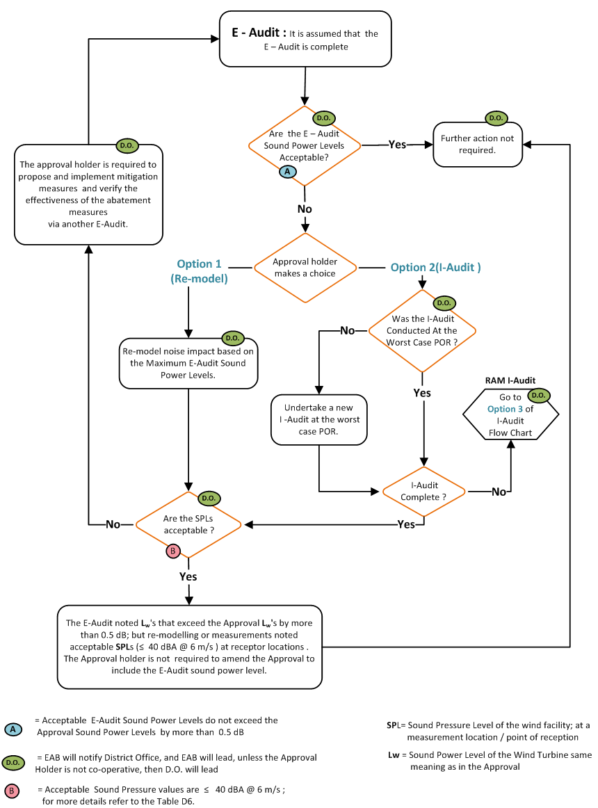
E5 I-Audit review process
E5.1 Complete submissions
If the I-Audit report is complete and demonstrates compliance with the Ministry’s sound level limits, the Director will inform the owner/operator of the wind facility, in writing, that the I-Audit report shows compliance with the Ministry’s sound level limits, and that no further action is required. Refer to section F, Appendix F7, for items which must be submitted with the audit.
The Ministry will also require that all Acoustic Audit reports
If a tonal assessment
If the I-Audit report is complete and demonstrates non-compliance with the Ministry’s sound level limits, the owner/operator of the wind facility will be required to submit a NAAP to the Director and the District Manager (please refer to Figure 2 in section E6 of this document). The owner/operator of the wind facility will usually be required to submit the NAAP within 60 days of receiving a written request from the Ministry to do so, or within a date agreed to by the Director and/or the District Manager. The Ministry will review and approve the NAAP.
The Ministry will typically require that the NAAP outline proposed mitigation measures (including timelines) to bring the wind facility into compliance with the Ministry’s applicable sound level limits. The NAAP will also be expected to include details about the completion and submission of a new I-Audit to the Ministry to verify that compliance has been achieved, following implementation of the mitigation measures.
E5.1.1 Notes on compliance
For the purposes of section E5.1 of this document, the Ministry will consider a wind facility to be in compliance if, for all point(s) of reception and/or measurement locations covered by the I-Audit, the measured sound level(s) is (are) less than or equal to the sound level limits as specified in section D6 of this document.
The Ministry will require that the I-Audit include a table summarizing the Point(s) of reception/measurement locations, as well as the rationale for why specific Point(s) of reception/measurement locations were chosen. Please refer to the table in section F, Appendix F3, for an example.
Where a NAAP is required, in the subsequent I-Audit report(s), the owner/operator of the wind facility will also be required to make a statement, with suitable rationale, indicating that the sound levels at all other Receptors identified in the Acoustic Assessment Report are in compliance with the applicable sound level limits.
E5.2 Incomplete submissions
If the I-Audit is incomplete, the owner/operator of the wind facility has the option to follow one of the three options set out below. Please also refer to Figure 2 in Section E6 of this document and Appendix F12. The options would allow the owner/operator to:
E5.3 Option 1: supplement audit results
Owner / operators of wind facilities may have measurement data that was not previously shared with the Ministry. The supplementary data may be sufficient to deem both I-Audits complete without further measurements. This option allows owners / operators to reassess the audit based on:
The revised audit can then be resubmitted to the Ministry.
E5.4 Option 2: combine audit results
If proceeding with this option, the Ministry will require the owner/operator of the wind facility to submit an interim report to the Ministry based on the partial information of the first I-Audit. This I-Audit will be required to include:
The Ministry will allow the owner/operator to combine the first I-Audit with the second I-Audit
Example 1
If the combination of the two I-Audits provides:
the Ministry will consider the I-Audit to be complete, and will apply the same compliance criteria and considerations as set out in section E5.1 above.
Example 2
If the combination of the two I-Audits does not provides sufficient data to fulfil the minimum data requirements as detailed in the Approval, the Ministry will require the owner/operator to submit two I-Audits using the revised assessment methodology for I-Audits (RAM I-Audit) specified in section E5.5 below.
E5.5 Option 3: analysis parameters for the RAM I-Audit
Revised assessment methodology for I-Audits
For this option, the Ministry will require the owner/operator of the wind facility to undertake an assessment based on Part D of this document, and as modified below. As noted in Part D of this document, the wind facility sound level is based on the logarithmic (energy) subtraction of the sound level when the turbines are operational and sound level when the turbines are parked.
In this section, “Turbine” means a turbine that has the greatest predicted noise impact at the subject receptor/measurement location.
The following items describe the assessment parameters that the Ministry will apply to the RAM I-Audit analysis:
E5.5.1 RAM I-Audit reporting requirements
E5.5.2 Notes on compliance
If a tonal assessment
Option 1: Supplement I-Audits with existing data
Owners/operators have the option of revisiting existing data that they may not have already shared with the Ministry, and supplementing their I-Audits with this data in an effort to complete the I-Audits.
Option 2: Combine audit results
As noted in section E5.4 of this document, if the combination of the two I-Audits provides sufficient data to fulfil the minimum data requirements as detailed in the Approval, the Ministry will consider the I-Audit to be complete. The same compliance criteria and considerations set out in section E5.1 of this document for the I-Audit Review Process for Complete Submissions would therefore be applicable.
Option 3: analysis parameters for the RAM I-Audit
The Ministry will consider a wind facility to be in compliance if, for all Point(s) of reception and/or measurement locations covered by the RAM I-Audit, the measured sound level(s) is (are) less than or equal to the sound level limits as specified in section D6 of this document.
The Ministry will require a table summarizing the point(s) of reception/measurement locations, as well as the rationale for why specific point(s) of reception/measurement locations were chosen to be included in the RAM I-Audit. Please refer to the table in section F, Appendix F3, for an example.
As part of the RAM I-Audit report, the owner/operator of the wind facility will also be required to make a statement, with suitable rationale, indicating that the sound levels at all other Receptors identified in the Acoustic Assessment Report are in compliance with the applicable sound level limits.
If the RAM I-Audit report demonstrates compliance with the Ministry’s sound level limits, the Director will inform the owner/operator of the wind facility, in writing, that the RAM I-Audit report shows compliance with the Ministry’s sound level limits, and that no further action is required.
If the RAM I-Audit report demonstrates non-compliance with the Ministry’s sound level limits, the owner/operator of the wind facility will be required to submit a NAAP to the district office and the Director. The owner/operator of the wind facility will usually be required to submit the NAAP within 60 days of receiving a written request from the Ministry to do so, or within a date agreed to by the Director and\or District Manager. The Ministry will review and approve the NAAP.
The Ministry will typically require that the NAAP outline proposed mitigation measures (including timelines) to bring the wind facility into compliance with the applicable sound level limits. The NAAP will also be expected to include details about the completion and submission of a new I-Audit to the Ministry to verify that compliance has been achieved, following implementation of the mitigation measures.
E6 I-Audit flow chart
Figure 2: I-Audit flow chart (with 3 options)
Note: Only for audits which were originally required to be based on the 2011 protocol.
Download printer-friendly flowchart (PNG)
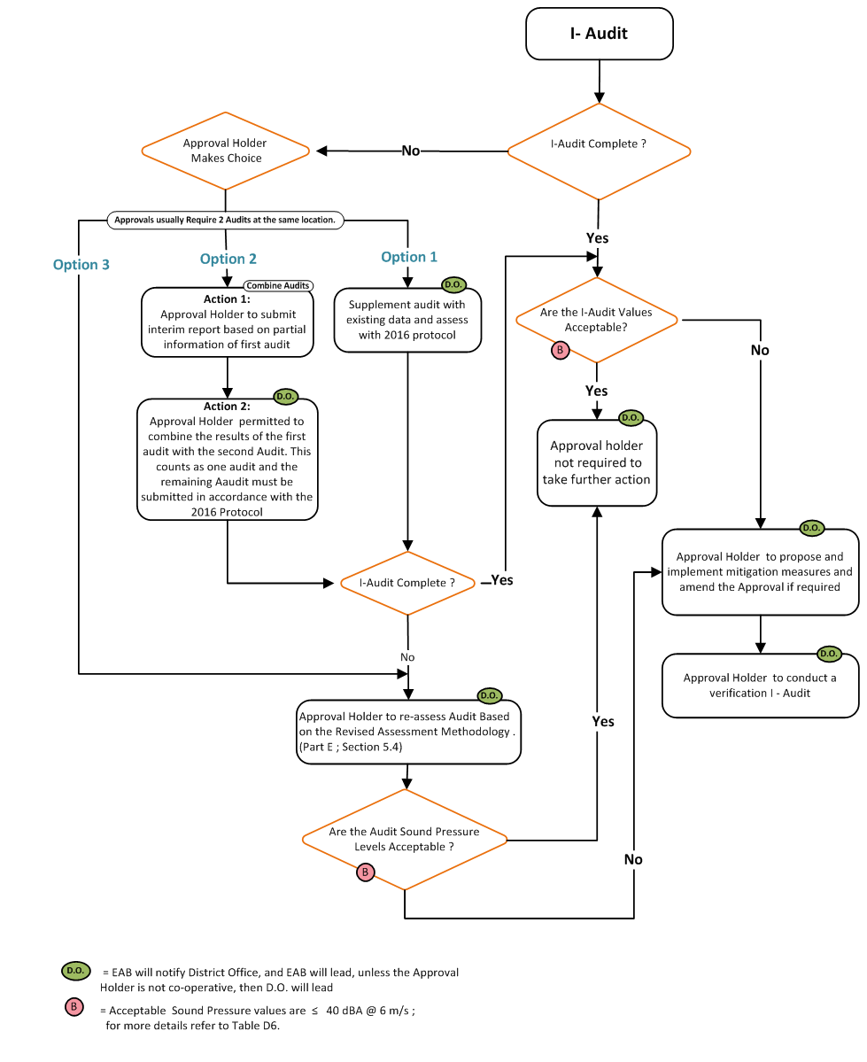
I-Audit complete
Are the I-Audit values acceptable? (Acceptable sound pressure values are ≤ 40 dBA at 6 m/s)
I-Audit not complete
Part F: Appendices
F1 Appendix A: Noise complaint form
Recommended interview questions:
Recommended complaint response procedures:
The following should be established:
Appendix F2: Overview of the qualitative assessment
The general steps identified in the qualitative assessment are included in the figure below:
Download printer-friendly flowchart (PNG)
Sample UTM analysis
SCB – corrected coordinates were adjusted 3 m in the Northing to adjust for the 1 m south setback and 2 m turbine base.
| ID | Noise assessment: Easting (m) Datum NAD 83 | Noise assessment: Northing (m) Datum NAD 83 | SCB – corrected coordinates : Easting (m) Datum NAD 83 | SCB – corrected coordinates : Northing (m) Adj Datum NAD 83 | Comparison: NA vs SCB |
|---|---|---|---|---|---|
| T45 | 391879 | 4678926 | 391877 | 4678930 | 4.47 |
| T46 | 384831 | 4668445 | 384836 | 4668446 | 5.10 |
| T47 | 384190 | 4669818 | 384193 | 4669820 | 3.61 |
| T48 | 382940 | 4670586 | 382945 | 4670570 | 5.39 |
| T49 | 382658 | 4670903 | 382662 | 4670907 | 5.66 |
| T50 | 382029 | 4671600 | 382034 | 4671604 | 6.40 |
| T51 | 387019 | 4667814 | 387025 | 4667818 | 7.21 |
| T52 | 386759 | 466811 | 386763 | 4668117 | 7.21 |
| T53 | 382926 | 4673818 | 382931 | 4673821 | 5.83 |
| T54 | 388889 | 4667532 | 388893 | 4667534 | 4.47 |
| T55 | 388653 | 4667799 | 388621 | 4667802 | 32.14 (this would require further follow-up to determine if it is a reduction > 4%) |
| T56 | 387925 | 4668258 | 387929 | 4668259 | 4.12 |
| T57 | 387354 | 4668709 | 387357 | 4668710 | 2.83 |
| T58 | 384720 | 4671289 | 384725 | 4671293 | 6.53 |
| T59 | 384248 | 4673243 | 384252 | 4673243 | 4.00 |
Appendix F3: Sample rationale summary for measurement locations
For I-Audit purposes the Points of Reception should be selected such that they represent the location of the greatest predicted noise impacts, i.e. the highest predicted sound levels; subject to the documented constraints imposed by the location of the Points of Reception:
If the owner / operator cannot access the site(s) of one or more of the preferred Points of Reception, the owner / operator must:
Refer to the table on the next page for an example of a sample rationale summary table for measurement locations.
An example of a sample rationale summary table for measurement locations
| Receptor ID | Description of receptor | Receptor Height (m) |
Distance to Closest Turbine (m) | Closest Turbine ID | Modelled sound level(dBA) |
Rationale |
|---|---|---|---|---|---|---|
| R3201 | Non-Participating receptor | 4.5 | 561 | T2 | 39.9 | Permission Not Granted |
| R3512 | Non-Participating receptor | 4.5 | 621 | T36 | 39.8 | Selected Monitoring Location |
| V6032 | Vacant Lot | 4.5 | 632 | T4 | 39.8 | Poor Monitoring Location (e.g. close to trees, roads) |
| V6028 | Vacant Lot | 4.5 | 661 | T6 | 39.7 | Selected Monitoring Location |
| R3456 | Non-Participating receptor | 4.5 | 703 | T3 | 39.5 | Not in Prevailing Wind Direction |
| R3698 | Non-Participating receptor | 1.5 | 612 | T8 | 39.4 | Poor Monitoring Location; farm noise prevalent |
| V6323 | Vacant Lot | 4.5 | 599 | T9 | 39.3 | Permission Not Granted |
| P3898 | Participating receptor | 4.5 | 761 | T20 | 38.9 | Selected Monitoring Location (PORs in the vicinity denied access to their property) |
| M1 |
Measurement Location (Not a point of reception or Participating receptor) | 4.5 | 550 | T15 | 38.8 | Selected Monitoring Location. Location chosen close to the turbine, as Ambient sound levels at other locations were high. |
Appendix F4: Resident triggered measurement form and example of results
Resident triggered measurement form
| # | Day | Date | Time | Noise Annoyance level, rated on a scale of 1-10 |
Comments; to be completed by home owner |
|---|---|---|---|---|---|
| 1 | Wednesday | July 20, 2016 | 9:04 AM | Not applicable | set up test |
| 2 | Wednesday | July 20, 2016 | 10:02 AM | 6 | audible sound from wind turbine (WTG6) and low background |
| 3 | Thursday | July 21, 2016 | 11:05 PM | 2 | high wind speed at ground level, wind turbine noise very low |
| 4 | Friday | July 22, 2016 | 8:09 AM | 5 | car passing by at 8:12 AM, wind turbine noise noticeable from 8:00 AM to 8:15 AM |
| 5 | Saturday | July 23, 2016 | 11:12 AM | 7 | Quiet background, audible noise from wind turbine (WTG2), continuous noise from 11:12 AM to 11:22 AM |
| 6 | |||||
| 7 | |||||
| 8 | |||||
| … | |||||
| 12 |
Example of results 1
Measurements
| # | Date | Audio recording activated | Wind turbines & background sound, 10 min Leq (dBA) | Wind turbines with exraneous noise, 10 min Leq (dBA) | Compliance indicated | Resident annoyance level | Ministry comments |
|---|---|---|---|---|---|---|---|
| 1 | March 26, 2016 | 5:18 PM | 43.0 | 33.1 | Yes | 5 | Door closing, people talking |
| 2 | March 26, 2016 | 10:20 PM | 36.0 | 36.0 | Yes | 6 | |
| 3 | March 27, 2016 | 7:57 AM | 38.8 | 36.1 | Yes | 3 | cow mooing |
| 4 | March 27, 2016 | 10:08 PM | 45.2 | 39.1 | Yes | 5 | wind gusts |
| 5 | March 28, 2016 | 12:03 AM | 43.7 | 38.2 | Yes | 7 | |
| 6 | March 28, 2016 | 2:51 AM | 44.1 | 39.8 | Yes | 8 | |
| 7 | March 28, 2016 | 2:23 PM | 43.9 | 39.2 | Yes | 8 | |
| 8 | March 28, 2016 | 2:46 PM | 49.4 | 39.8 | Yes | 8 | road traffic |
| 9 | March 29, 2016 | 3:44 AM | 41.2 | 39.2 | Yes | 7 | wind |
| 10 | March 31, 2016 | 10:02 PM | 45.3 | 40.1 | 7 | heavy rain | |
| 11 | March 31, 2016 | 10:29 PM | 45.5 | 35.6 | 9 | heavy rain | |
| 12 | April 1, 2016 | 4:03 AM | 44.1 | 33.8 | 7 | cat, strong wind |
Example of results 2
First weather station at 1.5 m height (optional)
| # | Temp. °C | Humidity (%) | Wind speed (m/s) | Wind direction (Clockwise; North is 0) | Environmental validity (Yes/No) |
|---|---|---|---|---|---|
| 1 | 2 | 72 | 2.2 | 243 | Yes |
| 2 | 4 | 84 | 4.3 | 264 | Yes |
| 3 | 6 | 64 | 4.6 | 266 | Yes |
| 4 | 5 | 65 | 4.9 | 12 | Yes |
| 5 | 4 | 71 | 6.1 | 254 | Yes |
| 6 | 6 | 72 | 1.2 | 302 | Yes |
| 7 | 10 | 74 | 2.6 | 18 | Yes |
| 8 | 11 | 78 | 4.2 | 304 | Yes |
| 9 | -6 | 82 | 0.5 | 44 | Yes |
| 10 | 11 | 95 | 1.7 | 265 | No, high humidity |
| 11 | 11 | 94 | 1.5 | 243 | No, high humidity |
| 12 | 4 | 90 | 0.1 | 0 | No, high humidity |
Second weather station at 4.5 m height (required for this receptor)
| # | Temp. °C | Humidity (%) | Wind speed (m/s) | Wind direction (Clockwise; North is 0) | Environmental validity (Yes/No) |
|---|---|---|---|---|---|
| 1 | 2 | 72 | 2.2 | 243 | Yes |
| 2 | 4 | 84 | 4.3 | 264 | Yes |
| 3 | 6 | 64 | 4.6 | 266 | Yes |
| 4 | 5 | 65 | 4.9 | 12 | Yes |
| 5 | 4 | 71 | 6.1 | 254 | Yes |
| 6 | 6 | 72 | 1.2 | 302 | Yes |
| 7 | 10 | 74 | 2.6 | 18 | Yes |
| 8 | 11 | 78 | 4.2 | 304 | Yes |
| 9 | -6 | 82 | 0.5 | 44 | Yes |
| 10 | 11 | 95 | 1.7 | 265.3 | No, high humidity |
| 11 | 11 | 94 | 1.5 | 243.2 | No, high humidity |
| 12 | 4 | 90 | 0.1 | 0 | No, high humidity |
Power and wind data at hub height for wind turbing T01 (the closest wind turbine)
| # | % Power (MW) | Average wind speed at hub height (m/s) | Wind direction – YAW direction | Tonal? (Y/N) only if there is a concern for tonality of the wind turbine |
|---|---|---|---|---|
| 1 | 4% | 4.2 | 12.1 | N |
| 2 | 30% | 7.2 | 90.1 | N |
| 3 | 20% | 4.5 | 114.2 | N |
| 4 | 100% | 12.6 | 106.5 | N |
| 5 | 98% | 11.9 | 108.0 | N |
| 6 | 96% | 12.8 | 112.1 | N |
| 7 | 98% | 12.1 | 157.4 | N |
| 8 | 99% | 12.5 | 160.7 | N |
| 9 | 100% | 12.5 | 216.0 | N |
| 10 | 99% | 13.4 | 17.2 | N |
| 11 | 99% | 13.1 | 22.8 | N |
| 12 | 97% | 11.9 | 84.4 | N |
Measurement at receptor for turbine, predicted level: dba, setback distance m
Download this sample chart (PNG)
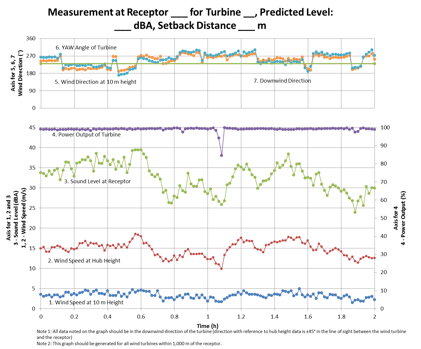
This chart is a sample illustration of what measured data would look like in graph form when using instrumentation and software typically used for this actitvity as described throughout this document. The receptor for which the measurement applies would need to be specified, as well as the turbine of interest, followed by the predicted noise level and setback distance in meters. This type of graph would be created for all wind turbines within 1,000 metres of the receptor.
Appendix F5: E-Audit checklist for IEC 61400-11:2002+A1:2006
Wind Energy Project – Screening Document – Acoustic Audit Report – Emission, IEC61400-11 Standard
Note 1: If conducting the Acoustic Audit – Emission using IEC61400-11:2013 standard, please use the Acoustic Audit Report – Emission, IEC61400-11:2013 standard screening document (not this document).
Note 2: Comments should include which section of the report the information can be found.
1. Characterization of the Wind Turbine
Items 1 to 26; IEC61400-11:2002+A1:2006, Section 9.1, Characterization of the wind turbine
Operating details:
Rotor details:
Gearbox details:
Generator details:
2. Physical environment
3. Measurement instrumentation
4. Acoustic data
Items 40 to 49; IEC61400-11:2002+A1:2006, Section 9.4, Acoustic Data
5. Non-acoustic data
6. Uncertainty
7. Additional information
Appendix F6: E-Audit checklist for IEC 61400-11:2013
Wind Energy Project – Screening Document – Acoustic Audit Report – Emission, IEC61400-11:2013 Standard
Information required in the Acoustic Audit Report – emission
Note 1: If conducting the Acoustic Audit – Emission using IEC61400-11:2002+A1:2006 standard, please use the Acoustic Audit Report – Emission, IEC61400-11:2002+A1:2006 standard screening document (not this document).
Note 2: Comments should include which section of the report the information can be found.
1. Characterization of the wind turbine
Items 1 to 26; IEC61400-11:2013, Section 10.2, Characterization of the wind turbine
Operating details:
Rotor details:
Gearbox details:
Generator details:
2. Physical environment
Items 27 to 33; IEC61400-11:2013, Section 10.3, Physical Environment
3. Measurement instrumentation
Items 34 to 39; IEC61400-11:2013, Section 10.4, Instrumentation
4. Acoustic data
Items 40 to 52; IEC61400-11:2013, Section 10.5, Acoustic Data
For each relevant wind speed (k):
5. Non-acoustic data
6. Uncertainty
Items 62 to 64; IEC61400-11:2013, Section 10.7, Uncertainty
The uncertainty of the following reported acoustic quantities shall be assessed and reported:
7. Additional information
Optional information for the Acoustic Audit Report – Emission
8. Acoustic data
Items 68 to 72; IEC61400-11:2013, Section 10.5, Acoustic Data
9. Non-acoustic data
Items 73 to 74 are from IEC61400-11:2013, Section 10.6, Non-Acoustic Data
Appendix F7: I-Audit checklist
Wind Energy Project – Screening Document – Acoustic Audit Report – Immission
Information Required in the Acoustic Audit Report – Immission
Appendix F8: Potential data illustrations and equipment set up
Download potential data illustration option 1 (PNG)
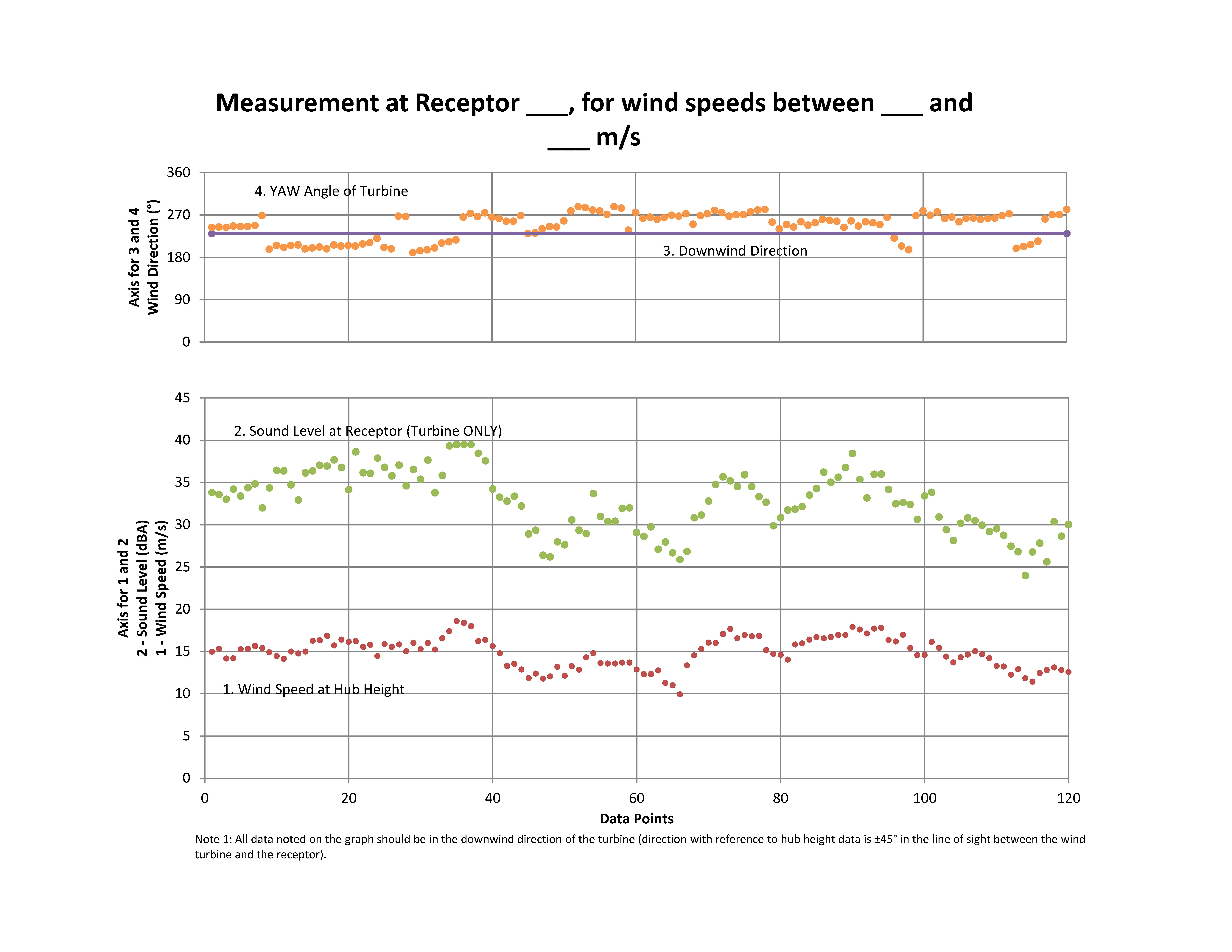
Please contact EAASIBGen@ontario.ca for a description of this figure.
Download potential data illustration option 2 (PNG)
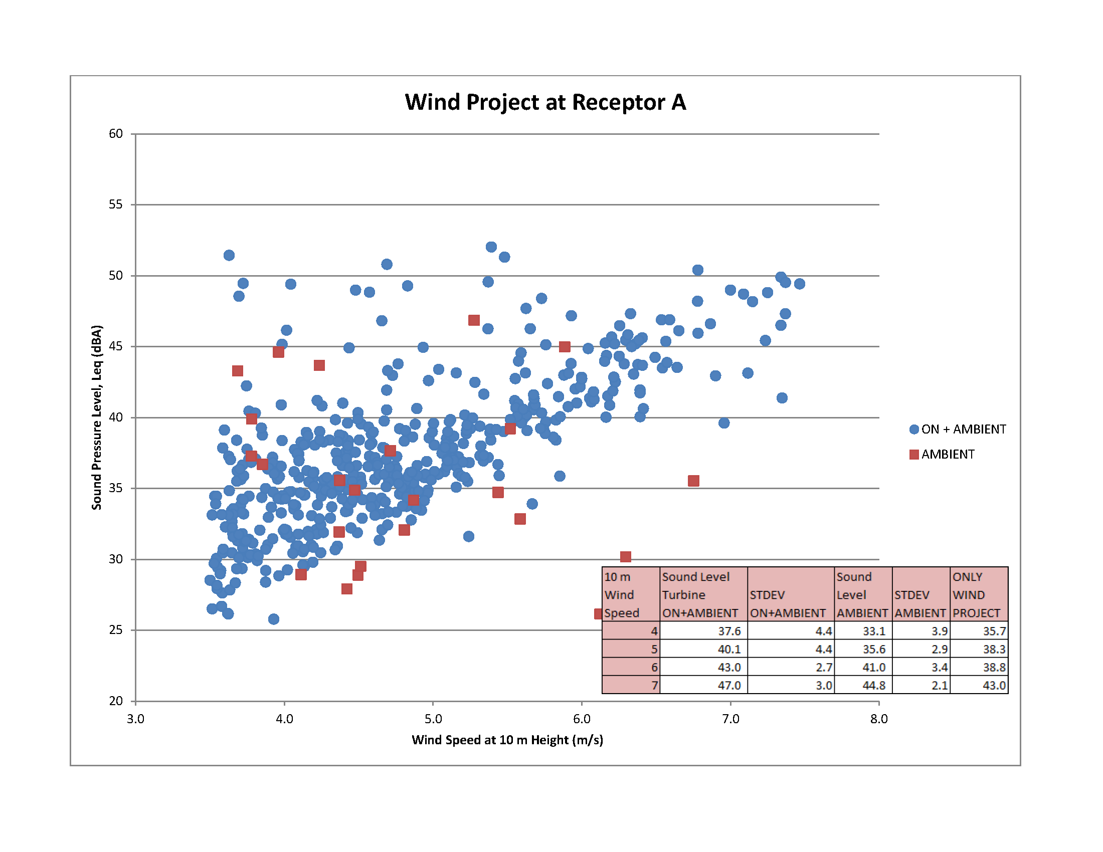
Please contact EAASIBGen@ontario.ca for a description of this figure.
Download potential data illustration option 3 (PNG)
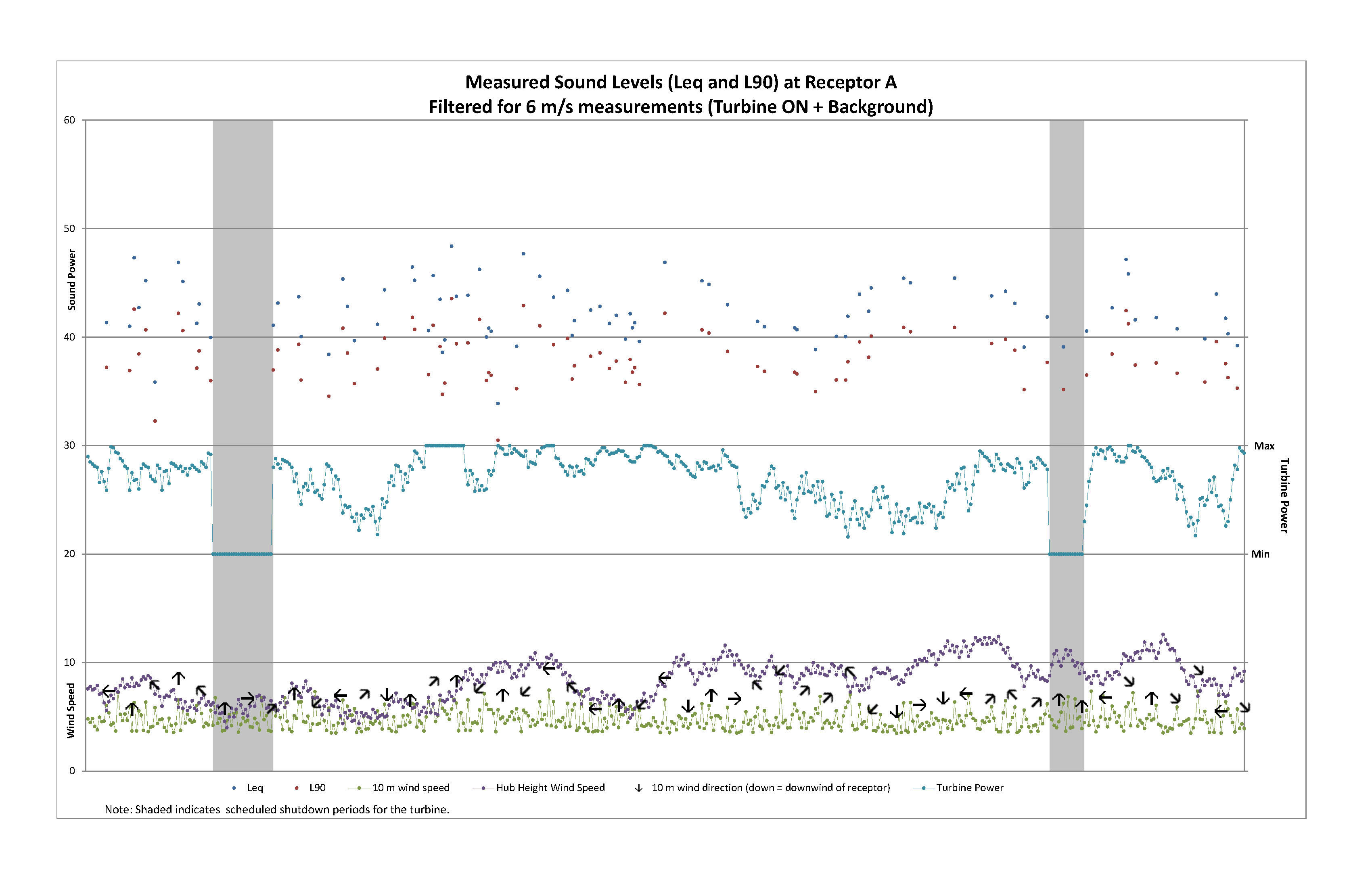
Please contact EAASIBGen@ontario.ca for a description of this figure.
Appendix F9: Illustration of equipment set up
These photographs show what the microphone set-up would look like in the field from three different vantage points once installed. The microphone position shall be sufficiently away from any large reflecting surfaces (minimum of 5 meters recommended). This requirement does not apply if using a small vertical reflecting board attached to the building facade. The microphone should be located at a point near the receptor dwelling that is not shielded from the closest wind turbine noise (or wind facility). Wherever possible, the microphone should not be located near deciduous trees or foliage.
Download illustration 1 (JPEG)
Download illustration 2 (JPEG)
Download illustration 3 (JPEG)
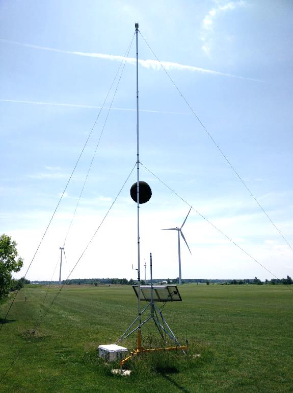
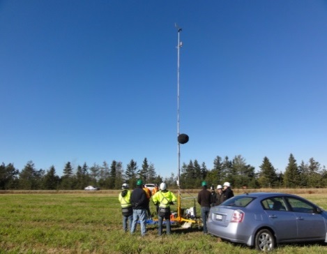
Appendix F10: Example for section D1.3
If the wind direction at the measurement location has the potential to influence (30 dBA or greater) the ambient measurements (for instance a nearby roadway), then if appropriate, the measurements should be filtered accordingly.
For example, if a roadway has the potential to influence the ambient measurements, the Practitioner will need to exercise judgment with respect to filtering wind direction during the ambient measurements, if the roadway will not influence the background sound level when the turbines will have the greatest noise impact at the measurement location.
See example below. Filtering the ambient to exclude measurements when wind is blowing from the west may be required.
Download example figure for section D1.3 (JPEG)
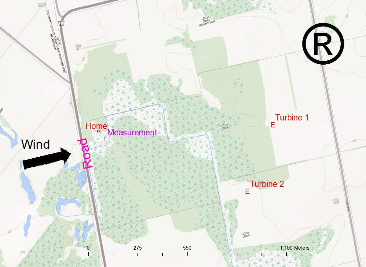
This figure is an illustration of a noise receptor in relation to two wind turbines, and a nearby roadway that contributes to ambient noise levels. In order to determine the ambient noise level, the ambient noise measurements are carried out with turbines in the vicinity of the noise receptor parked. The parked turbines are those that, if operating, would contribute to or would likely contribute to the ambient noise levels.
If the wind direction at the measurement location has the potential to influence the ambient measurements (for instance a nearby roadway), then if appropriate, the measurements should be filtered accordingly.
For example, suppose two turbines are situated about 950 meters to the east of the sound measuring instrumentation. Located about 130 meters to the west is a road. If wind is blowing from the west, filtering the ambient to exclude measurements from the wind or the road may be required.
Appendix F11: Example for Section E5.5.2(10)
In unique circumstances, the Ministry will consider not only the individual turbine with the highest predicted impact at the subject receptor, but a group of turbines that represent the greatest contribution at the receptor. Greatest contribution means turbines that have sound pressure levels that are up to two (2) dB lower at the receptor/measurement location than the turbine with the highest predicted impact at the receptor/measurement location.
With reference to the diagram below, the above condition would be satisfied if the turbines are located as noted in the diagram. The turbine (T1) with the highest predicted impact at the subject receptor is located to the east of the receptor and turbines T2 and T3 are located further to the east of the receptor. Turbines T2 and T3 also have an impact similar to, but at most 2 dB less, than the turbine T1. In this scenario, all three turbines (T1, T2 and T3) can be considered in the analysis. Consequently, the aggregate downwind angle can also be incorporated into the analysis.
The angle between the outer turbines, (turbine 1 and turbine 3 in this example) should not exceed 45 degrees.
In addition, downwind conditions now exist when any of the turbines are deemed to be downwind. In this example, the condition will exist when the wind direction is between -45 degrees of turbine 3 to +45 degrees of turbine 1.
Download example figure for section E5.5.2(10) (JPEG)
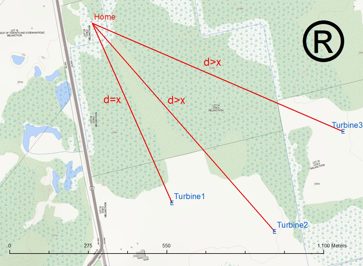
This figure illustrates the location of a home and three wind turbines to the southeast. The purpose of this illustration is the show a unique scenario where the Ministry will consider not only the individual turbine with the highest predicted impact at the subject receptor, but a group of turbines that represent the greatest contribution at the receptor. Greatest contribution means turbines that have Sound pressure levels that are up to two (2) dB lower at the Receptor location than the turbine with the highest predicted impact at the Receptor location.
The following table illustrates another interpretation of the concept using four scenarios. The bolded numbers indicate the turbines that would qualify to be included in the assessment.
Scenario 1
| Turbine ID | Turbine’s impact at the receptor location (dBA) | Total impact from all turbines at the receptor (dBA) |
|---|---|---|
| 1 | 38 | 39.8 |
| 2 | 31 | 39.8 |
| 3 | 31 | 39.8 |
| 4 | 25 | 39.8 |
| 5 | 25 | 39.8 |
Scenario 2
| Turbine ID | Turbine’s impact at the receptor location (dBA) | Total impact from all turbines at the receptor (dBA) |
|---|---|---|
| 1 | 36 | 39.9 |
| 2 | 35 | 39.9 |
| 3 | 31 | 39.9 |
| 4 | 30 | 39.9 |
| 5 | 25 | 39.9 |
Scenario 3
| Turbine ID | Turbine’s impact at the receptor location (dBA) | Total impact from all turbines at the receptor (dBA) |
|---|---|---|
| 1 | 35 | 39.4 |
| 2 | 34 | 39.4 |
| 3 | 34 | 39.4 |
| 4 | 25 | 39.4 |
| 5 | 22 | 39.4 |
Scenario 4
| Turbine ID | Turbine’s impact at the receptor location (dBA) | Total impact from all turbines at the receptor (dBA) |
|---|---|---|
| 1 | 34 | 39.9 |
| 2 | 33 | 39.9 |
| 3 | 33 |
39.9 |
| 4 | 32 | 39.9 |
| 5 | 32 | 39.9 |
With reference to the measurement location (vertex), only turbine configurations that are within an angle of 45 degrees can be considered in the assessment. The receptor building cannot shield the sound of the turbines.
Appendix F12: Summary of I-Audit Scenarios (Past, Present and Future Approvals)
All wind projects if required to conduct two (2) I-Audits at a location, must submit two I-Audits for that location.
| Scenario # | Status of project | Status of audits | Available option(s) |
|---|---|---|---|
| 1 | Operational | Both submitted and both incomplete | Option 1, 2 or 3 |
| 2 | Operational | One submitted | If the submitted audit is incomplete use Option 1, 2 or 3; If the submitted audit is complete, then second audit to be conducted as per this document. (variant of Option 3) |
| 3 | Operational | Audits not yet submitted | Option 1, 2 or 3 |
| 4 | Non-operational | Not due until 6-12 months after the facility is operational | Option 3 |
Option 1: Supplement Audits with Existing Data (and assess in accordance with this document).
Option 2: Combining Audit Measurements, and conduct an additional Audit based on this document.
Option 3: Conduct two Audits in accordance with this document.
- Type 1 sound level meter according to the IEC standard 61672-1 (2002), Reference [7].
- Class 1 or Class 2 microphone systems
footnote 7 It is noted that the Class 2 microphone may not strictly meet the requirements outlined in this section; however, the appropriateness of Class 2 microphones was demonstrated to the Ministry previously during field-testing. If Class 2 microphone systems are used, caution is advised to ensure that:- The noise floor of the microphones is below 25 dBA; and
- The frequency range is suitable between at least 20 Hz to 8,000 Hz, where the microphone response is effectively flat.
- Should the sound levels outside the range of such microphones be a concern, it is expected that more sensitive microphones be employed in those circumstances. .
- The instrumentation having a constant frequency response over the 20 Hz to 20,000 Hz frequency range.
- The filters meeting the requirements of IEC 61260 for Class 1 filters.
- The instrumentation being capable of measuring audio recordings continuously during the measurement campaign, at sampling rate of at least 8,000 Hz. Depending on the composition of the background sound levels, larger sampling rates (i.e. 44,000 Hz) may be required.
- This includes, but is not limited to:
- The dates of the measurement campaign
- The temperature range
- The general weather conditions
- The range of wind speeds encountered
- The Wind Rose
- A statement, signed by the operator of the wind facility, confirming that the wind turbines in question were:
- operating normally for the duration of the campaign (except during parked ambient noise measurements)
- when the turbines were parked (the turbine rotor was not rotating)
This statement should also be supported by electrical power output and rotational speed data for the relevant turbines.
- The result of the analysis outlined in section D5 should be presented both graphically and tabulated. (Refer to Section F of this document for examples illustrating the data). They should include:
- The total sound curve/levels
- The ambient sound curve/levels
- The turbine sound curve/levels
- Calculated standard deviation on all 3 sets, at each integer wind speed
The results must cover a wind speed range of at least 4-7 m/s (10 m height).
- Acknowledgement of whether Tonality was observed from the audio signals. If Tonality was observed, then details on how it was assessed should be provided as described in section D3.8.3.
- Comparison of the total contribution of the turbines (including Tonality) to the applicable sound level limit, and a statement of whether the wind facility is in compliance with those limits.
- the facility is unable to fulfill audit requirements in a timely manner (for example submitting the audit six (6) months after the due date of the audit in the Approval); or
- the facility delays the implementation of a NAAP (for example by six (6) months).
- the E-Audit shows that the measured sound power levels of the wind turbines (or wind facility) exceed the sound power levels set out in the Approval;
- the remodeled/measured sound levels demonstrate compliance with the Ministry’s sound level limits at the Points of Reception; and
- the Ministry will not take further action or require that the Approval be amended
footnote 10 .
- bring the wind facility into compliance with the applicable sound level limits, or
- mitigate time periods (i.e. night-time 7:00 pm to 7:00 am) when the noise levels are over the Ministry guidelines, (i.e. the operator has options such as de-rating turbines and/or curtailing the wind turbine operation under specific conditions, (wind speeds/direction)).
- The measured sound level at the point of reception with the greatest predicted noise level is less than or equal to the Ministry’s applicable sound level limit; or
- The measured/calculated sound power levels of subject turbines are less than or equal to the sound power level(s) in the Approval plus 0.5 dB.
- Slant distance R1 is defined in References [1] and [6] in Figure 4 as the "slant distance" from rotor centre to the actual measurement position "i". If this distance (R1) does not include the horizontal distance from rotor centre (hub) to the tower axis, then the value calculated for R1 is not acceptable.
- If the analysis is based on Reference [1], it is not acceptable to use the bin analysis of the acoustic energy (average of each bin) instead of the polynomial method to calculate the apparent sound power level, as long as the correlation coefficient is 0.8 or greater. Please refer to section 8.3 of Reference [1] for further clarification.
- The acquisition of E-Audit data over several measurement campaigns (for example different seasons: spring, summer or fall) is not acceptable. Measurement over several seasons is not considered to be a short period of time (six weeks is considered a short period of time).
Different seasons may have different ambient vegetation and atmospheric patterns, which could compromise the integrity of the results. Measurements of sound pressure levels and wind speeds should be made simultaneously over short periods of time and over the required range of wind speeds.
- During the sound level measurement campaign, the use of a ten (10) second averaging time in place of a one (1) minute averaging time is acceptable.
- The use of different methodologies to calculate the turbine wind speeds (turbine power curve and anemometer at 10 m height) when the power curve is a flat line (maximum electrical output is achieved) is acceptable if the results are conservative.
- sound data (e.g. sound data for higher wind speeds, such as 9 and 10 m/s), or
- supporting data to confirm that the background sound level was too high to measure the turbine sound,
- E-Audit: It is assumed that the E-Audit is complete.
- Are the E-Audit sound power levels acceptable? (Acceptable E-Audit sound power levels do not exceed the approval sound power levels by more than 0.5 dB) (EAB will notify District Office, and EAB will lead, unless the Approval Holder is not co-operative, then D.O. will lead). If yes, further action not required.
- If no, approval holder makes a choice:
- Option 1 (Re-model). Re-model noise impact based on the maximum E-Audit sound power levels. Are the SPLs acceptable? (Acceptable sound pressure values are ≤ 40 dBA at 6 m/s; for more details refer to the Table D6)
- If yes, the E-Audit noted Lw's that exceed the Approval Lw's by more than 0.5 dB; but re-modelling or measurements noted acceptable SPLs (≤ 40 dBA at 6 m/s) at receptor locations. The Approval holder is not required to amend the Approval to include the E-Audit sound power level. Further action is not required. (EAB will notify District Office, and EAB will lead, unless the Approval Holder is not co-operative, then D.O. will lead)
- If no, the approval holder is required to propose and implement mitigation measures and verify the effectiveness of the abatement measures via another E-Audit. Return to Step 1. (EAB will notify District Office, and EAB will lead, unless the Approval Holder is not co-operative, then D.O. will lead)
- Option 2 (I-Audit). Was the I-Audit conducted at the worst case POR?
- If no, undertake a new I-Audit at the worst case POR.
- If yes, is the I-Audit complete?
- If no, go to Option 3 of I-Audit flow chart (EAB will notify District Office, and EAB will lead, unless the Approval Holder is not co-operative, then D.O. will lead)
- If yes, are the SPLs acceptable? (Acceptable sound pressure values are ≤ 40 dBA at 6 m/s; for more details refer to the Table D6)
- If yes, the E-Audit noted Lw's that exceed the Approval Lw's by more than 0.5 dB; but re-modelling or measurements noted acceptable SPLs (≤ 40 dBA at 6 m/s) at receptor locations. The Approval holder is not required to amend the Approval to include the E-Audit sound power level. Further action is not required. (EAB will notify District Office, and EAB will lead, unless the Approval Holder is not co-operative, then D.O. will lead)
- If no, the approval holder is required to propose and implement mitigation measures and verify the effectiveness of the abatement measures via another E-Audit. Return to Step 1. (EAB will notify District Office, and EAB will lead, unless the Approval Holder is not co-operative, then D.O. will lead)
- Option 1 (Re-model). Re-model noise impact based on the maximum E-Audit sound power levels. Are the SPLs acceptable? (Acceptable sound pressure values are ≤ 40 dBA at 6 m/s; for more details refer to the Table D6)
- the measured sound levels at the measurement locations; or
- if applicable, the measured sound levels plus the tonal penalty at the measurement locations.
- supplement the audit results,
- combine the audit results of two measurement campaigns, or
- use a revised assessment methodology (RAM I-Audit described in section E5.5 of this document) to assess compliance.
- data previously collected, and
- on the parameters specified in this section E5.4 of this document.
- A measurement period of at least six (6) consecutive weeks
- The owner/operator’s initial (pre-construction) annual Wind Rose, wind speed and summer nighttime wind shear data for the site
- A cover letter noting what percentage of the measurement data was acquired
- sufficient data to fulfil the minimum data requirements as detailed in the Approval, and
- the background sound levels in both audits are consistent / similar,
- The objective of the RAM I-Audit is to assess the acoustic immission at the measurement location at wind speeds between 1 and 7 m/s (inclusive). At a minimum, data must be acquired to satisfy the requirements of at least one of the following:
- three (3) of the wind speed bins between 1 and 7 m/s (inclusive), or
- two (2) of the wind speed bins between 1 and 4 m/s (inclusive).
- The owner/operator of the wind facility will be required to verify that all wind turbines and transformers within the facility are operating within the manufacturer’s performance parameters (i.e. there are no maintenance issues).
- Only downwind data will be considered in the analysis. With reference to the Turbine location, downwind directions are ±45 degrees from the line of sight between the Turbine and receptor/measurement location. The downwind direction should be based on the yaw angle of the Turbine. In addition, the receptor anemometer wind direction and wind speed (at a 10 m height) should also be reported.
- The analysis should only be based on data when the Turbine’s sound power level is approximately equal to or greater than 85% of its rated electrical power output and at least 90%
footnote 15 of its maximum sound power level. - The Ministry may accept a reduced number of data points for each wind speed bin with appropriate justification (i.e. 60 data points in place of 120 for turbine operational measurements and 30 data points in place of 60 data points for ambient measurements). The acceptable number of data points will be influenced by the quality of the data (standard deviation).
- If the measurement campaign is unable to acquire the minimum number of ambient sound level data, the owner/operator of the wind facility will be permitted to use one of the provisions described below:
- use the ambient sound level data from a lower wind speed bin to represent a higher wind speed bin (i.e. if 6 m/s data is unavailable, the owner/operator is permitted to use 5 m/s data to represent the 6 m/s data bin), or
- use a value of 30 dBA.
- The Ministry, on a case-by-case basis, may also accept sound level measurements based on a shorter averaging time, for all data points in all wind speed bins, rather than the current one (1) minute averaging time (minimum interval 10 seconds). However, in such cases, the equivalent data set should be comprised of :
- a minimum of 120 minutes of data per wind speed bin for the turbine operational measurements, and
- 60 minutes of data per wind speed bin when the turbines are parked.
- The Ministry will permit the data filtering criterion as noted in section D5.2(3) of this document to be modified as noted below:
The objective value for the standard deviation of the sound level in each relevant wind speed bin (comprised of the mean of the one (1) minute equivalent sound level measurements) is 2 dB, with the exceptions of wind speed bins 6 and 7 m/s which should not exceed 2.5 dB.
- All measurements should be taken at least 5 m from any objects (e.g. trees, cars, trailers, etc.). Where impractical, documentation must be included in the report to support the chosen measurement location.
- In unique circumstances, the Ministry will consider not only the individual turbine with the highest predicted impact at the subject receptor, but a group of turbines that represent the greatest contribution at the receptor. Greatest contribution means turbines that have sound pressure levels that are up to two (2) dB lower at the receptor/measurement location than the turbine with the highest predicted impact at the receptor/measurement location.
In addition, with reference to the measurement location (vertex), only turbine configurations that are within an angle of 90 degrees can be considered in the assessment.
Refer to Appendix F11 for more details.
- At a minimum, the analysis should be based on six (6) weeks of measurements unless the required data is obtained in less time.
In the event that the required data is not acquired within six (6) weeks of measurements, then on a case-by-case basis, the Ministry may permit appropriate (statistical) data analysis, where necessary to derive valid conclusions (i.e. statement of compliance), in accordance with good scientific data analysis techniques.
- The Ministry will require the RAM I-Audit report to be submitted in hard and electronic form and to include the following information:
- The data used in the analysis (in an Excel spreadsheet), such as, but not limited to, the:
- Wind speed at the measurement location (10 m height)
- Wind speed at the hub height of the turbine
- sound pressure level at the measurement location
- Wind direction at hub height
- Wind direction at the measurement location
- The as built co-ordinates and approved UTM co-ordinates of all turbines and transformer substations in the wind facility (in an Excel spreadsheet).
- The measurement location identification nomenclature and UTM co-ordinates in the approved Acoustic Assessment Report : (i.e. POR 256; UTM (456,897: 4,678,897)).
- If the measurement location is not a Point of reception or Participating receptor, then a unique measurement location descriptor is required in addition to the predicted sound level at the measurement location.
- If applicable, all communication with the Ministry related to the choice of the measurement location.
- The data used in the analysis (in an Excel spreadsheet), such as, but not limited to, the:
- The Ministry will require the owner/operator of the wind facility to provide the following for all turbines within 1,500 m of the measurement location(s), and if possible, include data for adjacent wind facilities (10 minute interval data is acceptable):
- the electrical power output and RPM of turbines
- hub height wind direction, yaw angle
- hub height wind speed
- The Ministry will require the RAM I-Audit to include a map and at least three pictures taken at the measurement locations noted below:
- One picture should be taken at the measurement location in the direction of the Turbine
- One picture should be taken in close proximity to the Turbine in the direction of the measurement location
- Another picture should be taken at 90 degrees to the line between the Turbine and the measurement location. This picture should include the area in the vicinity of the microphone and the receptor.
- the measured sound at the measurement locations; or
- if applicable, the measured sound levels plus the tonal penalty at the measurement locations.
- If yes, approval holder not required to take further action. (EAB will notify District Office, and EAB will lead, unless the Approval Holder is not co-operative, then D.O. will lead)
- If no:
- Approval holder to propose and implement mitigation measures and amend the approval if required. (EAB will notify District Office, and EAB will lead, unless the Approval Holder is not co-operative, then D.O. will lead)
- Approval holder to conduct a verification I-Audit. (EAB will notify District Office, and EAB will lead, unless the Approval Holder is not co-operative, then D.O. will lead)
- Approval holder makes choice. Approvals usually require 2 audits at the same location.
- Option 1: Supplement audit with existing data and assess with 2016 protocol. Proceed to step 2. (EAB will notify District Office, and EAB will lead, unless the Approval Holder is not co-operative, then D.O. will lead)
- Option 2: Action 1: Approval Holder to submit interim report based on partial information of first audit. (Combine Audits) Action 2: Approval Holder permitted to combine the results of the first audit with the second Audit. This counts as one audit and the remaining Audit must be submitted in accordance with the 2016 protocol. Proceed to step 2. (EAB will notify District Office, and EAB will lead, unless the Approval Holder is not co-operative, then D.O. will lead)
- Option 3: Proceed to step 3.
- I-Audit complete?
- If yes, follow steps under the "I-Audit complete" heading.
- If no, proceed to step 3.
- Approval holder to re-assess audit based on the Revised Assessment Methodology (Part E; Section 5.5) (EAB will notify District Office, and EAB will lead, unless the Approval Holder is not co-operative, then D.O. will lead)
- Are the audit sound pressure levels acceptable? (Acceptable sound pressure values are ≤ 40 dBA at 6 m/s)
- If yes, approval holder not required to take any further action. (EAB will notify District Office, and EAB will lead, unless the Approval Holder is not co-operative, then D.O. will lead)
- If no:
- Approval holder to propose and implement mitigation measures and amend the approval if required. (EAB will notify District Office, and EAB will lead, unless the Approval Holder is not co-operative, then D.O. will lead)
- Approval holder to conduct a verification I-Audit. (EAB will notify District Office, and EAB will lead, unless the Approval Holder is not co-operative, then D.O. will lead)
- When did the noise become a problem?
- Where on the property is the noise a problem? (i.e. inside or outside the house).
- When is the noise a problem? (i.e. nighttime, weekdays, season, etc.)
- What is the duration of the noise issues? (This will help in deciding the approach for attended measurements)
- Describe the ambient conditions when noise is a problem (i.e. wind strength, wind general direction, approximate temperature, precipitation, other)
- What are the ambient conditions when the noise is not a problem? (What else is audible?)
- Compared to other noise sources in the area, why is this noise a problem? (i.e. louder, distinct pitch, other characteristics).
- A minimum timeline for contacting the individual making the complaint should be established. Two (2) business days from the time the Ministry is informed of the complaint would be adequate or provisions noted in the Approval. In this initial contact, a preliminary assessment of the situation should be provided and an action plan for follow-up including scheduling a time for a site visit;
- A timeline to either resolve the complaint or to provide the next update to the individual making the complaint; and
- A full description of activities undertaken to investigate the complaint and actions taken to address the cause of the incident(s) to which the complaint relates.
- < 1500 m? If no, no further action required. If yes, proceed to Step 2.
- Site visit questionnaire. Site visits are carried out by District staff.
- Setback reduced > 4%?
- If no, proceed to Step 4.
- If yes, remodel. If < 40 dBA, consider quantitative assessment tools. If not, abatement. No further action.
- Check predicted sound level (model result). If ≤ 35 dBA, no further action. If not, consider quantitative assessment tools.
- provide the Director and District Manager clear and substantiated evidence
footnote 17 why the site(s) cannot be accessed; - select one or more alternate measurement locations such that they represent the location of the greatest predicted noise impacts; and
- obtain the written consent of the Director before proceeding with the Acoustic Audit – Immission at the alternate measurement location(s).
- manufacturer
- model number
- serial number/turbine ID
- vertical or horizontal axis wind turbine
- upwind or downwind rotor
- hub height
- horizontal distance from rotor centre to tower axis
- diameter of rotor
- tower type (lattice or tube)
- passive stall, active stall, or pitch controlled turbine
- constant or variable speed
- power curve (if required for wind speed determination)
- rotational speed at each integer standardized wind speed from 6 to 10 m/s and at rated power
- pitch angle at each integer standardized wind speed from 6 to 10 m/s
- rated power output
- control software version
- rotor control devices
- presence of vortex generators, stall strips, serrated trailing edges
- blade type
- number of blades
- manufacturer
- model number
- fixed-parallel-shaft or planetary gearbox
- manufacturer
- model number
- rotational speed
- details of the site including location, site map and other relevant information
- type of topography/terrain (hilly, flat, cliffs, mountains, etc.) in surrounding area (nearest 1 km)
- surface characteristics (such as grass, sand, trees, bushes, water surfaces)
- nearby reflecting structures such as buildings or other structures, cliffs, trees, water surfaces
- other nearby sound sources possibly affecting background noise level, such as other wind turbines, highways, industrial complexes, airports
- two photos, one taken in the direction of the turbine from the reference microphone position, and one taken from the wind mast toward the turbine
- a photo of the microphone on the measurement board positioned on the ground and immediate surroundings, see Figure 2 of IEC61400-2002+A1:2006
- the manufacturer(s)
- the instrument name and type
- serial number(s)
- other relevant information (such as last calibration date, calibration certificate(s))
- anemometer position and measured height for each measurement series
- influence of secondary wind screen, if used
- the measured position of each microphone for each measurement series
- LWA,k, where LWA,k is the apparent sound power level, at each integer wind speed from 6 to 10 m/s and a graph of background corrected normalised values. The axes of the graph shall be linear, and scaled such that 1 m/s corresponds to 2 dB
- a plot showing all measured data pairs at position 1 of the wind turbine sound and background noise (with different symbols). On the plot, the axes of LAeq and Vs shall be linear, and scaled so that 1 m/s corresponds to 2 dB, where LAeq is the equivalent continuous A-weighted sound pressure level, and Vs is the standardized wind speed
- table and plot of sound pressure spectrum in third octaves for each integer wind speed from 6 to 10 m/s; coordinates plotted at 1 octave = 10 dB, and levels marked with an asterisk as appropriate. For each integer wind speed (k = 6, 7, 8, 9, 10):
- ΔLtn,j,k (for j = 1, 2, 3,…12) for each identified tone, where Ltn,j,k is the Tonality of the jth spectra at the kth wind speed
- ΔLk for each identified tone, where Lk is the Sound pressure level
- ΔLa,k for each identified tone, where La,k is the tonal audibility
- frequency of the tone(s)
- a typical 10 s energy averaged spectrum indicating the classification of spectral lines for each identified tone
- time and date of each measurement series
- Items 50 to 53, and 56; IEC61400-11:2002+A1:2006, Section 9.5, Non-Acoustic Data
- Items 54 and 55; NPC-233, Section 12.3, Acoustic Audit – Acoustical Data, bullet point number 8, All necessary and supporting calculations
- wind speed determination method
- air temperature
- atmospheric pressure
- roughness length
- the horizontal distance between the microphone measurement location and the turbine base, R0
- the slant distance, R1, or the differences in height between the microphone measurement location and the turbine base, hA
- the range of the wind direction during each measurement series (averages over 1 min periods)
- the apparent sound power level at integer wind speeds
- one-third octave band spectrum of the noise at the reference position at each integer wind speed
- the Tonality of the sound emissions of the wind turbine measured at the reference position
- Item 60; NPC-233, Section 10, Report Format, bullet point number 4, Conclusions and Recommendations
- Item 61; NPC-233, Section 12.3, Acoustic Audit – Acoustical Data, bullet point number 8, All necessary and supporting calculations
- Item 62; NPC-233, Section 12.3, Acoustic Audit – Acoustical Data, bullet point number 3, Details of measurement procedure
- Compliance statement
- All data included in an Excel spreadsheet
- If deviations from standard; was justification of the deviations provided
- manufacturer
- model number
- serial number/turbine ID
- vertical or horizontal axis wind turbine
- upwind or downwind rotor
- hub height
- horizontal distance from rotor centre to tower axis
- diameter of rotor
- tower type (lattice or tube)
- passive stall, active stall, or pitch controlled turbine
- constant or variable speed
- power curve (if required for wind speed determination)
- rotational speed at each integer wind bin
- rated power output
- control software version
- rotor control devices
- presence of vortex generators, stall strips, serrated trailing edges
- blade type
- serial number
- number of blades
- manufacturer
- model number
- serial number
- manufacturer
- model number
- serial number
- details of the site including location, site map and other relevant information;
- type of topography/terrain (hilly, flat, cliffs, mountains, etc.) in surrounding area (nearest 1 km);
- surface characteristics (such as grass, sand, trees, bushes, water surfaces);
- nearby reflecting structures such as buildings or other structures, cliffs, trees, water surfaces;
- other nearby sound sources possibly affecting background noise level, such as other wind turbines, highways, industrial complexes, airports;
- two photos, one taken in the direction of the turbine from the reference microphone position, and one taken from the wind mast toward the turbine;
- a photo of the microphone on the measurement board positioned on the ground and immediate surroundings, see Figure 2 of IEC61400-11:2013.
- the manufacturer(s);
- the instrument name and type;
- serial number(s);
- other relevant information (such as last calibration date, calibration certificate(s));
- met mast anemometer position and height for each measurement series;
- influence of secondary wind screen, if used.
- the measured position of each microphone for each measurement series;
- LWA,k, where LWA,k is the apparent sound power level, at bin centre wind speeds at hub height;
- LWA,k, where LWA,k is the apparent sound power level, at wind speeds at 10 m height;
- a plot showing all measured data pairs at position 1 of the wind turbine sound and background noise (with different symbols). On the plot, the axes of LAeq, and Vs shall be linear, and scaled so that 1 m/s corresponds to 2 dB, where LAeq is the equivalent continuous A-weighted sound pressure level, and Vs is the standardized wind speed;
- a plot showing all measured total noise versus electrical power data;
- table and plot of sound power spectrum in third octaves for each relevant wind speed; coordinates plotted at 1 octave = 10 dB, and levels bracketed as appropriate;
- table showing total noise and background noise, with values that are calculated as the energy sum of the average one-third octave band spectra for each bin. The corrected LAeq at bin centre values shall be calculated from the corrected one-third octave band spectrum at the bin centre can be included in the table. If the difference between total noise and background noise is between 3 and 6 dB, the result shall be marked with an asterisk. If the difference is three or less, the result shall not be used;
- ΔLtn,j,k (for j = 1, 2, 3,…12) for each identified tone, where Ltn,j,k is the Tonality of the jth spectra at the kth wind speed;
- ΔLk for each identified tone, where Lk is the sound pressure level;
- ΔLa,k for each identified tone, where La,k is the tonal audibility;
- frequency of the tone(s);
- narrowband spectra of total and background noise as an overlay plot per bin;
- time and date of each measurement series.
- Items 53 to 58, and 61; IEC61400-11:2013, Section 10.6, Non-Acoustic Data
- Items 59 and 60; NPC-233, Section 12.3, Acoustic Audit – Acoustical Data, bullet point number 8, All necessary and supporting calculations
- wind speed determination method;
- plots of wind speed from the power curve relative to measured nacelle wind speed and met mast measured wind speed;
- rotor rotational speed;
- air temperature;
- atmospheric pressure;
- roughness length (estimated);
- the horizontal distance between the microphone measurement location and the turbine base, R0;
- the slant distance, R1, or the differences in height between the microphone measurement location and the turbine base, hA;
- the range of the downwind direction during the measurement including the method used to ensure the yaw direction was within ±15° of the microphone position.
- description of type B uncertainties;
- apparent sound power levels at bin centre wind speeds;
- one-third octave band spectrum of the noise at the reference position at each integer wind speed.
- Item 65; NPC-233, Section 10, Report Format, bullet point number 4, Conclusions and Recommendations
- Item 66; NPC-233, Section 12.3, Acoustic Audit – Acoustical Data, bullet point number 8, All necessary and supporting calculations
- Item 67; NPC-233, Section 12.3, Acoustic Audit – Acoustical Data, bullet point number 3, Details of measurement procedure
- Compliance statement
- All data included in an Excel spreadsheet
- Deviation from standards and justification of deviation
- low frequency noise;
- infrasound;
- impulsivity;
- amplitude modulation;
- other noise characteristics, if any.
- estimates or measurements of the turbulence intensity during acoustic measurements;
- whether the turbulence intensity data were determined by measurement or by inference from meteorological conditions.
- Did the Sound level Meter meet the Type 1 Sound level meter requirements according to the IEC standard 61672-1 Sound level Meters, Part 1: Specifications? Section D2.1.1
- Was the complete sound measurement system, including any recording, data logging or computing systems calibrated immediately before and after the measurement session at one or more frequencies using an acoustic calibrator on the microphone (must not exceed ±0.5dB)? Section D2.1.3
- Are valid calibration certificate(s) of the noise monitoring equipment and calibration traceable to a qualified laboratory? Is the validity duration of the calibration stated for each item of equipment? Section D2.3
- Was the predictable worst case parameters such as high wind shear and wind direction toward the Receptor considered? Section D3.2
- Is there a Wind Rose showing the wind directions at the site? Section D7 (1e)
- Did the results cover a wind speed range of at least 4-7 m/s as outlined in section D 3.8.?
- Was the weather report during the measurement campaign included in the report? Section D7 (1c)
- Did the audit state there was compliance with the limits at each wind speed category? Section D6
- Are pictures of the noise measurement setup near Point of reception provided? Section D3.3.2 & D3.4
- Was there justification of the Receptor location choice(s) prior to commencement of the I-Audit? Section D4.1
- Was there sufficient valid data for different wind speeds? Section D5.2 # 3
- Was the turbine (operational) specific information during the measurement campaign in tabular form (i.e. wind speed at hub height, anemometer wind speed at 10 m height, air temperature and pressure and relative humidity) Section D3.7
- Were all the calculated standard deviations at all relevant integer wind speeds provided? Section D7 (2d)
- Compliance statement
- All data included in an Excel spreadsheet
- If deviations from standard; was justification of the deviations provided
Footnotes
- footnote[1] Back to paragraph Incomplete acoustic audits are those that deviate from the applicable guidance document without adequate justification, or audits that have not fulfilled the minimum data acquisition requirements.
- footnote[2] Back to paragraph When two I-audits are required and the first one is submitted before the date this document takes effect, the second I-audit will be subject to Part D of this document in its entirety (i.e. downwind data and 85% power output).
- footnote[3] Back to paragraph When two I-audits are required and the first one is submitted before the date this document takes effect, the second I-audit will be subject to Part D of this document in its entirety (i.e. downwind data and 85% power output).
- footnote[4] Back to paragraph In the context of this measurement campaign, the Ministry will not assign a decibel value to significant. If applicable, the value will be determined on a case-by-case basis.
- footnote[5] Back to paragraph Given the long term and outdoor nature of the measurements, along with special wind screen requirements (outlined in section C3.3.4), and with the understanding that Class 1 microphone systems are designed for indoor lab settings, some Class 2 microphone systems may be used.
- footnote[6] Back to paragraph A "wav file" is a Microsoft and IBM audio file format standard for storing an audio bit stream on a personal computer.
- footnote[8] Back to paragraph Acceptable means that the Ministry deemed the explanation / justification suitable for the particular measurement campaign under review.
- footnote[9] Back to paragraph The sound power level used in the remodelling should represent the worst-case scenario. For example, if more than one sound power value is available for a particular model of turbine (based on approved E-Audits) in a subject facility, the highest sound power level should be used when remodelling turbines which were not audited.
- footnote[11] Back to paragraph Summary documents are also acceptable but upon request, the complete audit should be made available.
- footnote[12] Back to paragraph Summary documents are also acceptable but upon request, the complete audit should be made available.
- footnote[13] Back to paragraph The tonal assessment should be conducted in accordance with the procedure in Reference [1], or at the Director’s discretion, compliant with another equivalent standard / procedure.
- footnote[14] Back to paragraph The combination of audits is acceptable provided the Background Sound levels in both audits are consistent / similar.
- footnote[16] Back to paragraph The tonal assessment should be conducted in accordance with the procedure in Reference [1], or at the Director’s discretion, compliant with another equivalent standard.
- footnote[18] Back to paragraph Receptor height should be either 4.5 or 1.5 m.
- footnote[19] Back to paragraph Table should be sorted by highest modelled sound level to lowest modelled sound level. Preferably, all receptors/measurement locations with predicted sound levels of 37 dBA and higher should be included.
- footnote[20] Back to paragraph Selected Monitoring Locations should be highlighted.
- footnote[21] Back to paragraph Registered letters were sent to the receptors and are documented (date of the registered letter and address of the recipient) and included in the audit report.
- footnote[22] Back to paragraph Registered letters were sent to the receptors and are documented (date of the registered letter and address of the recipient) and included in the audit report.
- footnote[23] Back to paragraph Registered letters were sent to the receptors and are documented (date of the registered letter and address of the recipient) and included in the audit report.
- footnote[24] Back to paragraph Subject to the Ministry’s written approval.
- footnote[25] Back to paragraph An annoyance level of 1 means the least amount of annoyance and an annoyance level of 10 means the greatest amount of annoyance.
- footnote[26] Back to paragraph In the above scenario it is assumed Turbine 3 is excluded as it does not fulfil the 45-degree criterion.
- footnote[7] Back to paragraph Given the long term and outdoor nature of the measurements, along with special wind screen requirements (outlined in section D 2.1.4), and with the understanding that Class 1 microphone systems are designed for indoor lab settings, some Class 2 microphone systems may be used.
- footnote[10] Back to paragraph This does not preclude the Ministry from requiring future acoustic audits, based on valid complaints from residents.
- footnote[15] Back to paragraph Percentage based on energy/logarithmic calculation.
- footnote[17] Back to paragraph Registered letters sent to the receptors that document (date of the registered letter and address of the recipient) efforts of communication with the owners of the dwelling. The correspondence should be included in the audit report.