Design, construction and maintenance of irrigation reservoirs
Learn about the design, construction and maintenance of pumped irrigation reservoirs. This information is for commercial crop producers in Ontario.
ISSN 1198-712X, Published May 2016
Introduction
This fact sheet provides general guidelines for the design, construction and maintenance of pumped irrigation reservoirs in Ontario.
An irrigation reservoir can provide a farm with the irrigation water supply needed. Having a secure, dependable irrigation water supply is important to maintaining production in dry years.
Combining an irrigation reservoir with a low yielding well can result in sufficient water supply. Pairing an irrigation reservoir with winter/spring pumping from a stream can result in sustainable farm water supplies while avoiding stream pumping during summer low flow periods.
Irrigation reservoirs store water pumped from an approved water source for use at a later date. A well-designed, constructed and maintained irrigation reservoir project should:
- provide adequate water storage for the projected irrigation needs
- provide an efficient and cost-effective operation of the irrigation system
- minimize water loss from storage
- minimize maintenance requirements
- minimize both maintenance and construction costs
- provide a safe and secure water storage system
Types of irrigation reservoirs
There are three types of irrigation reservoirs (Figure 1):
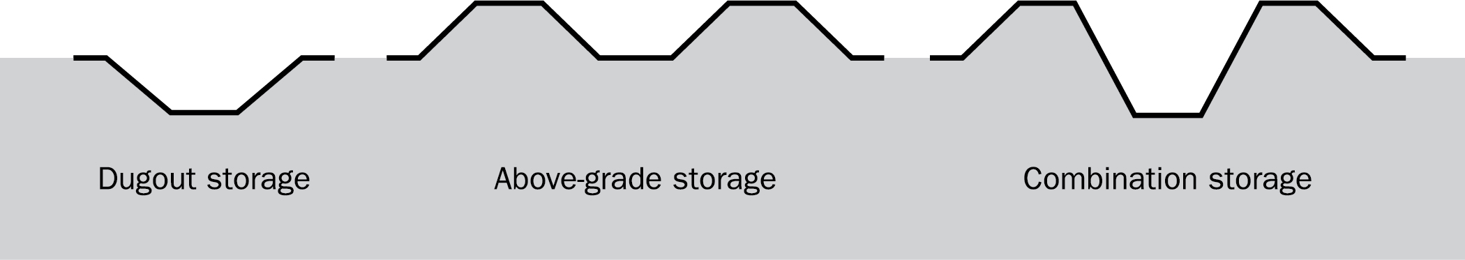
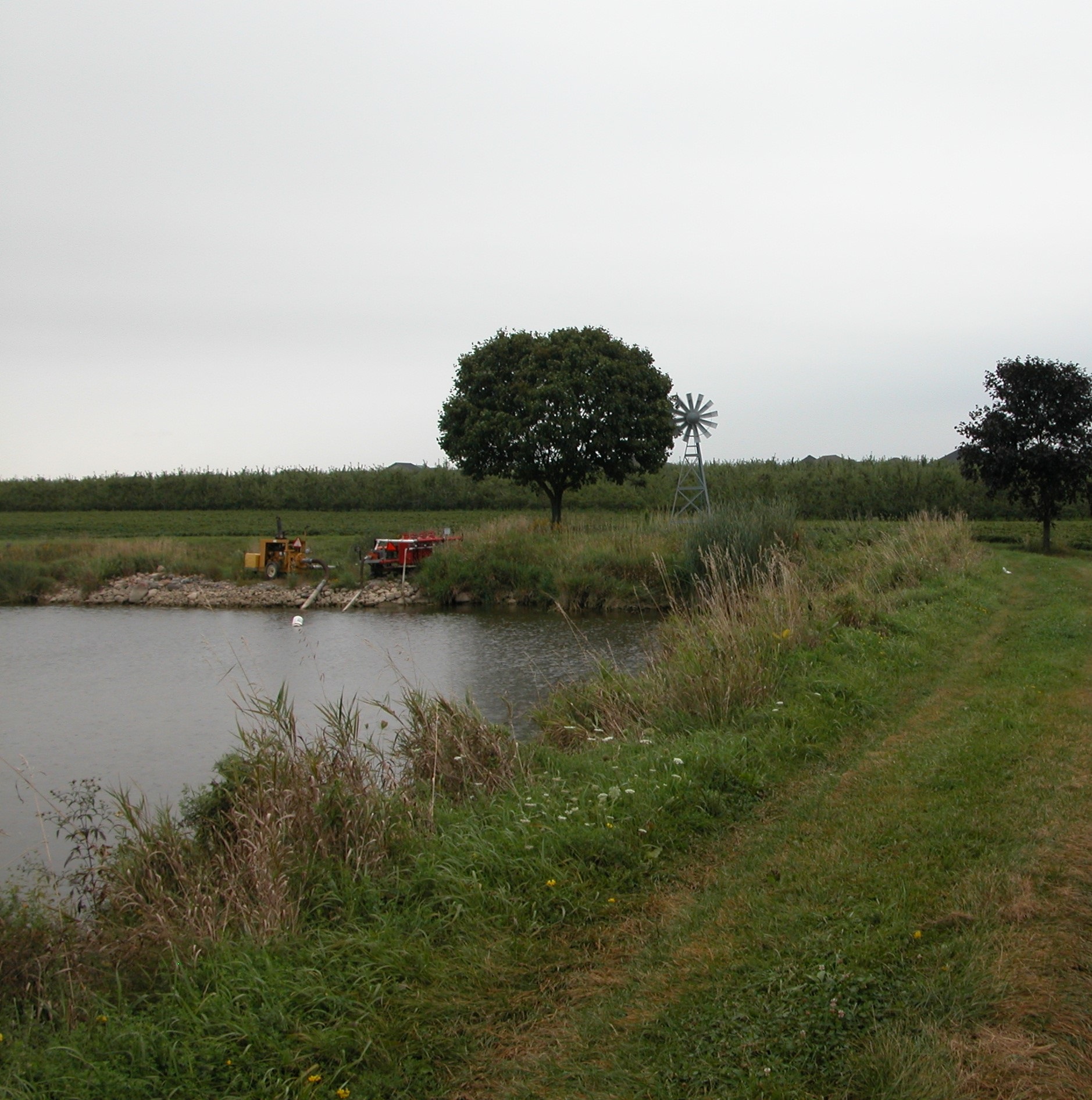
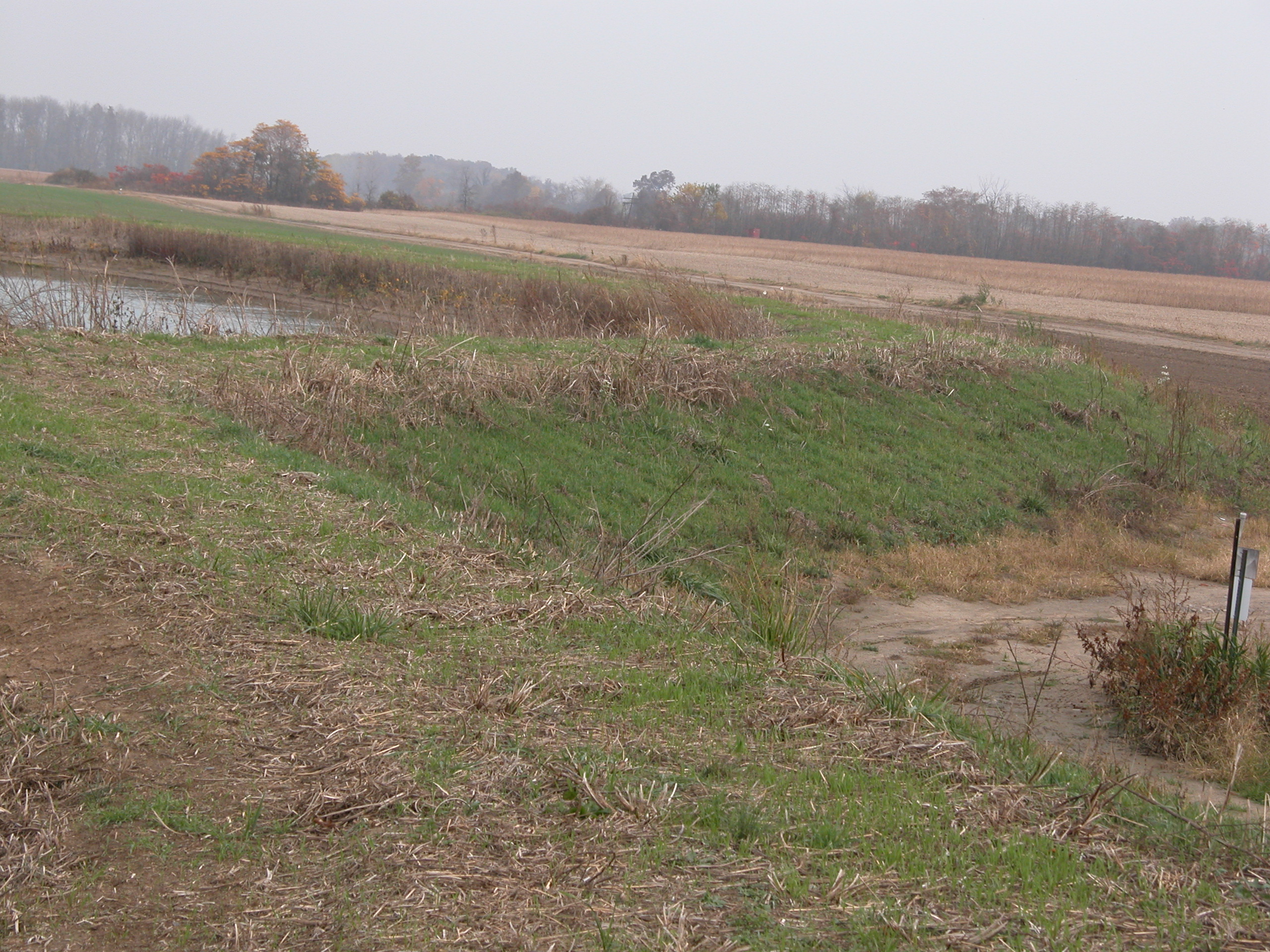
Dugout storage is below grade (normal ground level). Large amounts of soil is excavated and disposed of during construction (Figure 2).
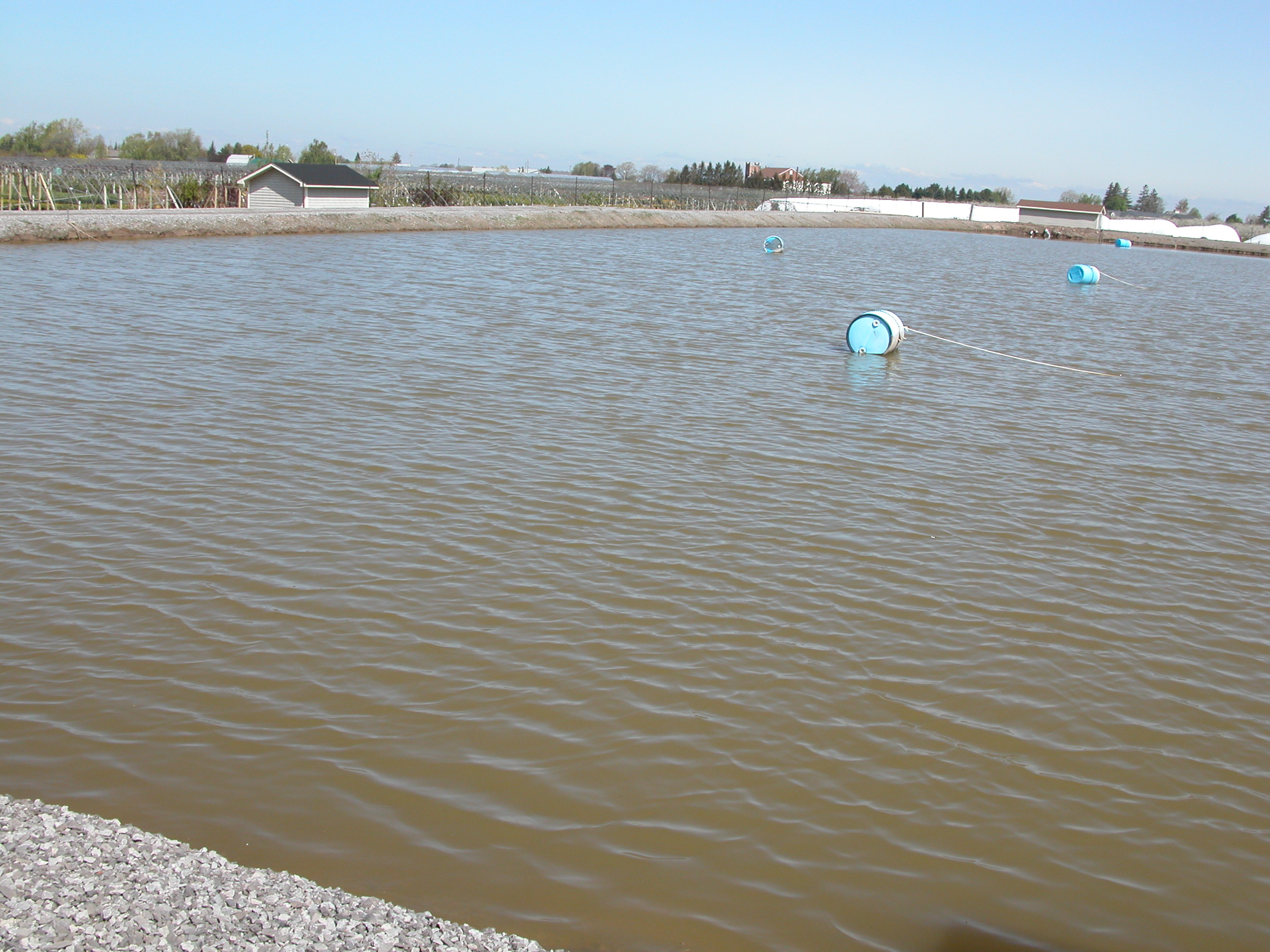
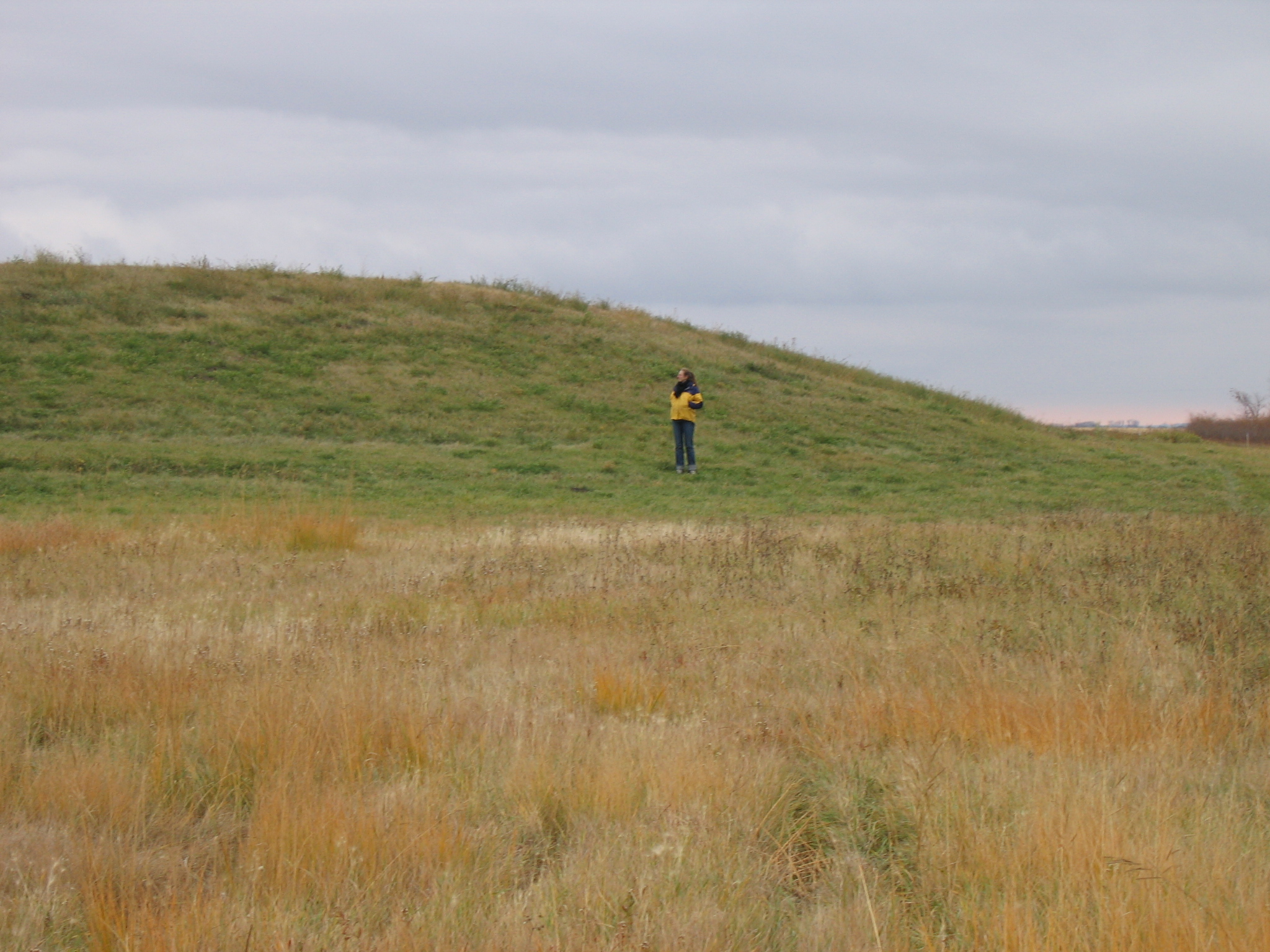
Above grade bermed storage consists of four-sided berms constructed completely above ground to retain water. A large quantity of clay (impermeable) soil is required to build the berms and construction is similar to the construction of dams (Figure 3). This reservoir type is primarily used in areas with poor subsoil conditions such as bedrock.
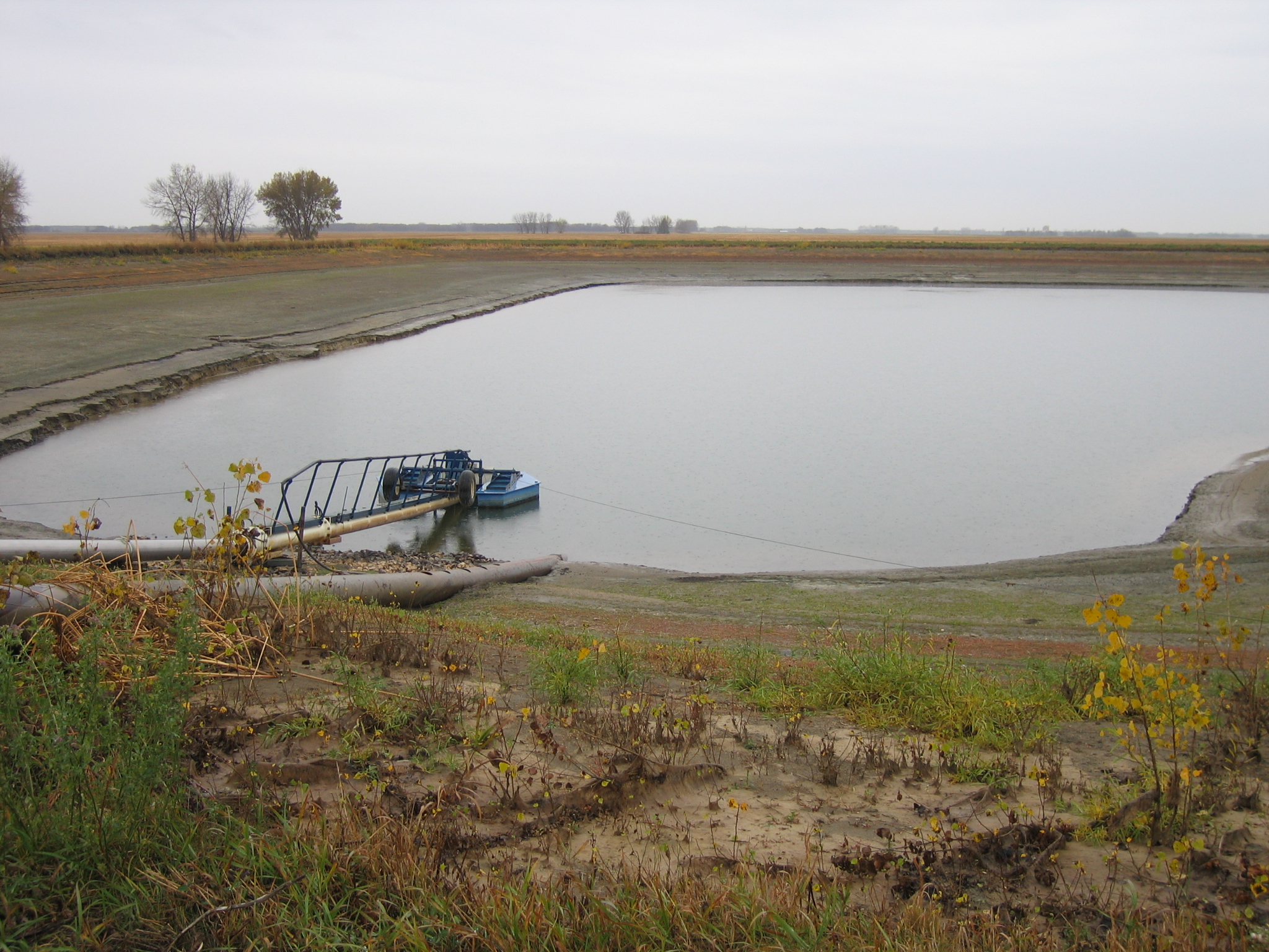
Combination storage is both below and above grade (Figure 4). The excavated soil is used to construct berms around the excavation for additional above-grade water storage. This type of construction is usually the most efficient use of the excavated material.
This Factsheet focuses on the construction of the combination storage type. However, the principles of design and construction also apply to the other two types of storage.
Storage size
Several factors affect the volume of storage required:
- area of the crop being irrigated
- type of crop being irrigated
- the expected number and frequency of irrigations
- how often the reservoir can be refilled
Once the required storage volume is determined, calculate various reservoir layouts based on a range of water surface areas and depths (Tables 1 and 2). Remember, the shallower the reservoir, the larger the surface area and the more land area used for the project.
| Length (m) | Width (m) | Berm Height (m) | Total Depth (m) | Reservoir Footprint (m2) | Reservoir Footprint (acres) | Water Volume (m3) | Water Volume (Acre-inches) |
|---|---|---|---|---|---|---|---|
| 100 | 100 | 3 | 8 | 15,376 | 3.8 | 40,122 | 390 |
| 100 | 50 | 3 | 8 | 9,176 | 2.3 | 13,626 | 133 |
| 50 | 50 | 3 | 8 | 5,476 | 1.4 | 5,130 | 50 |
| 50 | 50 | 1.5 | 5 | 4,225 | 1.0 | 5,324 | 52 |
| 50 | 30 | 1 | 4.5 | 2,604 | 0.6 | 2,356 | 23 |
| Length (m) | Width (m) | Berm Height (m) | Total Depth (m) | Interior Slopes | Exterior Slopes | Reservoir Footprint (m2) | Reservoir Footprint (acres) | Water Volume (m3) | Water Volume (Acre-inches) |
|---|---|---|---|---|---|---|---|---|---|
| 100 | 100 | 3 | 8 | 3:1 | 3:1 | 15,376 | 3.8 | 40,122 | 390 |
| 100 | 100 | 3 | 8 | 6:1 | 4:1 | 16,900 | 4.2 | 20,519 | 200 |
| 50 | 50 | 3 | 8 | 3:1 | 2.5:1 | 5,041 | 1.2 | 5,130 | 50 |
| 50 | 50 | 3 | 8 | 3:1 | 3:1 | 5,476 | 1.4 | 5,130 | 50 |
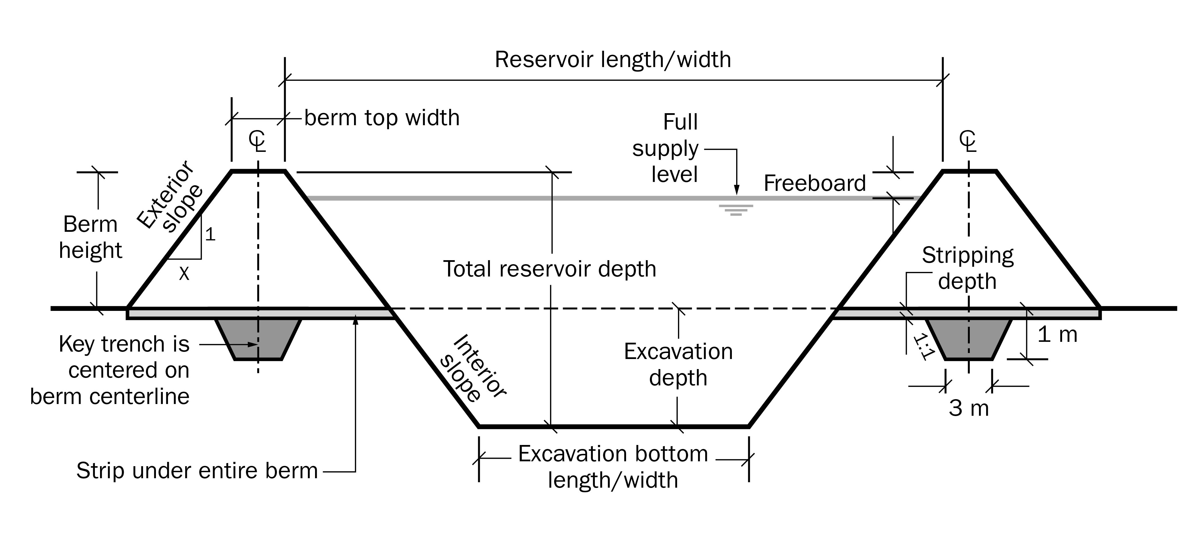
A reservoir with 3:1 inside slopes and 3:1 outside slopes; 3 m top of berm width; 10% of reservoir depth is reserved for freeboard.
A reservoir with 3 m top of berm width; 10% of reservoir depth is reserved for freeboard.
Alberta Agriculture provides a handy calculation tool to determine reservoir holding capacity from planned dimensions.
Location
Locate the reservoir:
- close to the water source that will be used to fill it, to minimize pumping costs
- in a central location to the fields being irrigated, to minimize piping and pumping costs
- away from homes, buildings and public roads so that public and local infrastructure is protected from damage in the case of a major failure
When selecting a site for the reservoir, consider the following:
- If feasible, ensure the availability of electrical power.
- Ensure proximity to access roads.
- Identify and avoid any areas with utilities, communication lines, pipelines, etc.
- Try to select a site with low-productivity land.
- Do not interfere with existing crop and field management practices.
- Identify any subsurface drainage and alterations that would need to be completed if a reservoir were to be constructed there.
- Select a location with clayey subsoil to allow for the construction of the reservoir from on-site water-holding materials. Importing clay from another site or using synthetic liners substantially adds to the project cost.
It is difficult to find a site that incorporates all of these requirements. Options and decisions will be influenced by cost and operational preferences. The goal is to choose the site that best incorporates all of the factors.
Site investigation
A site investigation of the soil is extremely important to determine suitability for the construction of a water reservoir. Conduct an initial site assessment by checking existing soil information on available soil maps followed by a more detailed site investigation under the direction of an experienced soil professional. These professionals are usually found working in engineering consulting firms.
Required soil texture
Adequate clay content will minimize or eliminate water seepage through the bottom and sides of the reservoir. The ideal site would have subsoil with a minimum of 15% clay content, uniformly distributed throughout, to a depth greater than that of the proposed excavation.
With suitable clay content, the portion of the reservoir below the normal ground grade will retain water. Also, the excavated clay is used to construct the berms for the portion of the reservoir storage above the normal ground grade. Otherwise, clay needs to be found at another site to line the reservoir.
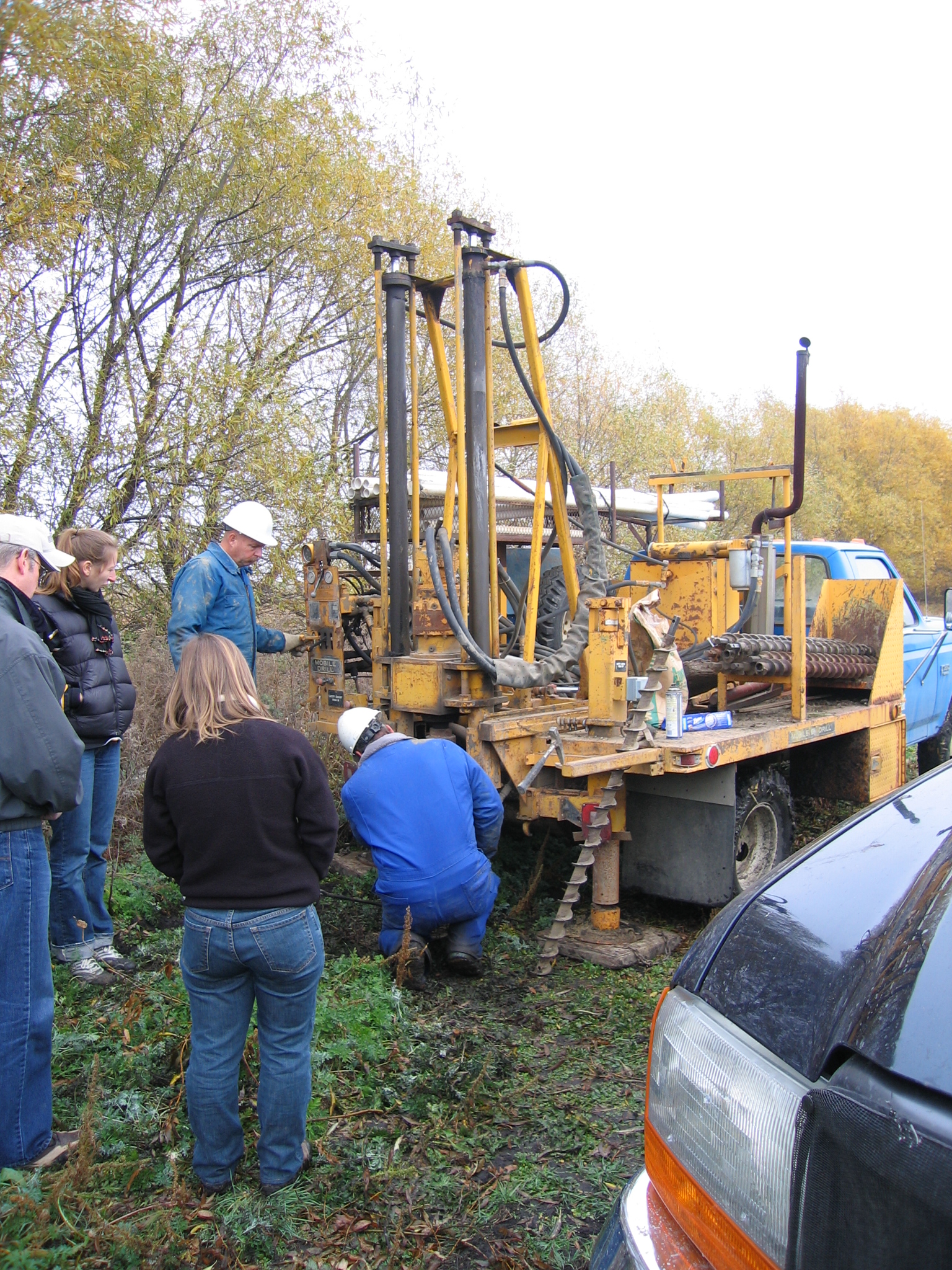
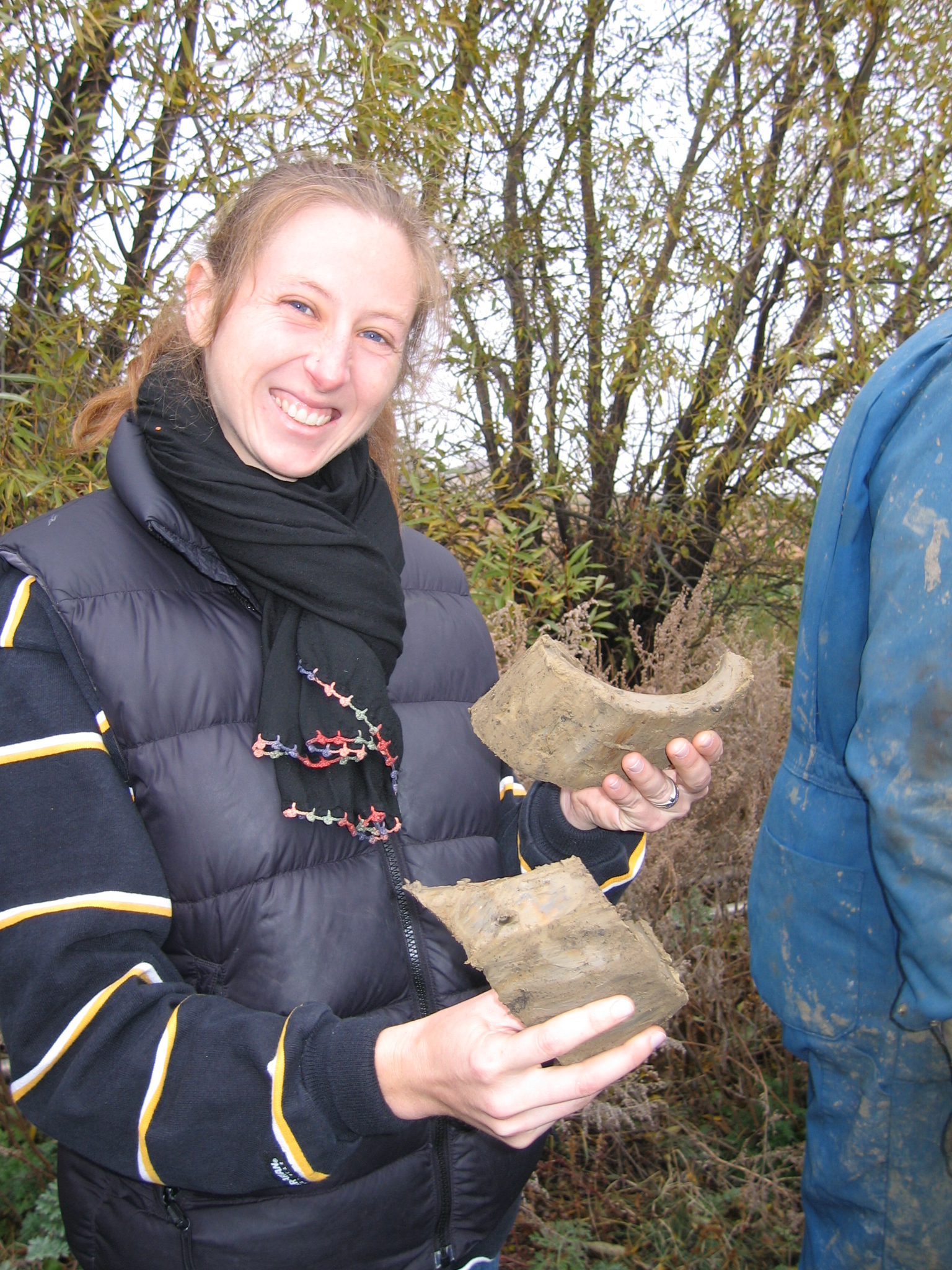
Investigation process
A good site investigation includes taking test holes using backhoes, drills, augers or specialized boring machines so the soil samples can be assessed for their clay content, suitability for water retention, lining material and berm construction (Figure 5). Record the test holes locations, including GPS coordinates, along with descriptions of the soil profiles (called a drilling log).
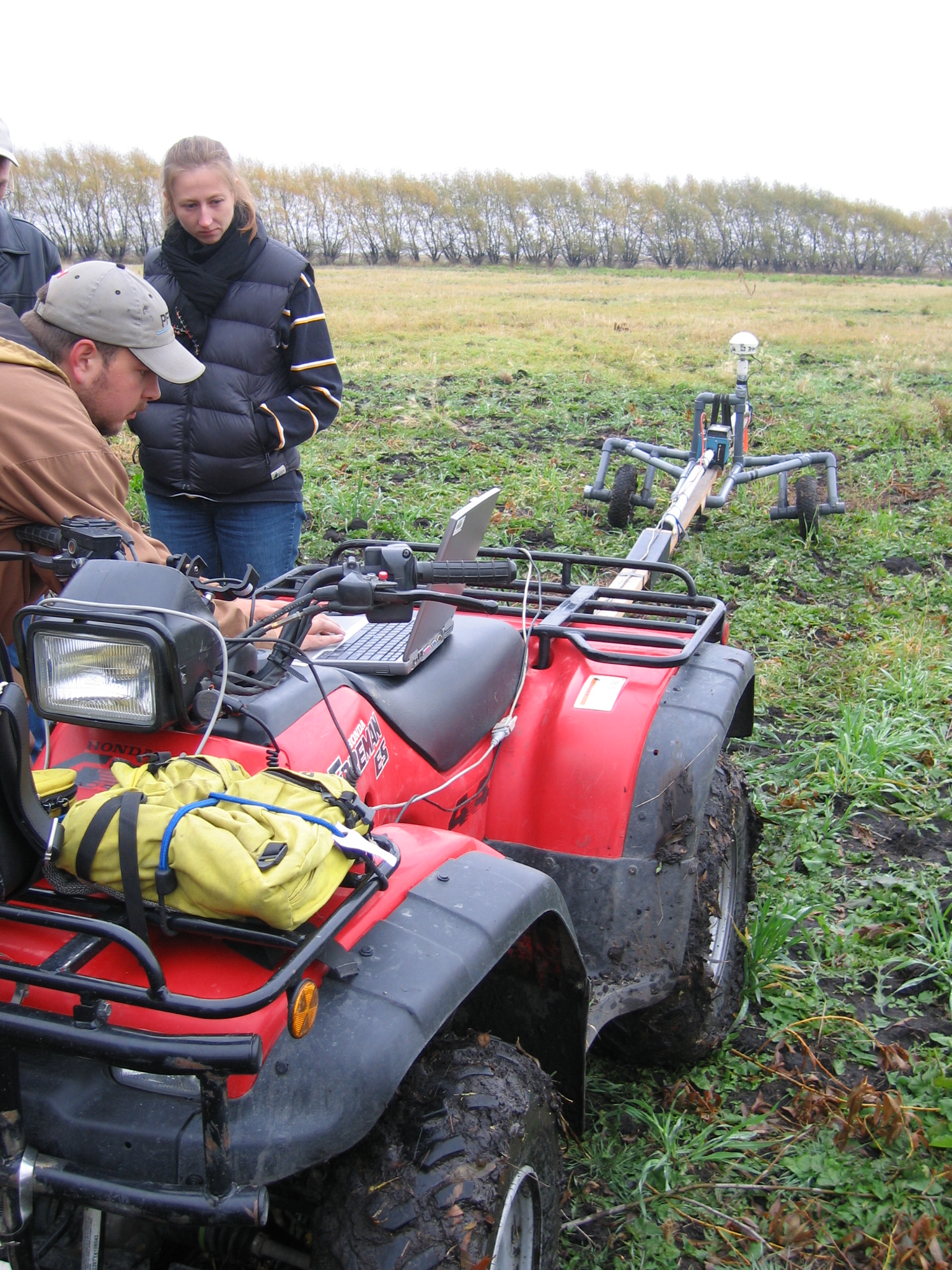
More advanced technology is also available to help with soil investigations. An electromagnetic (EM) survey is a technique which, without any excavation, can indicate where clay may be concentrated on the farm (Figure 6). The EM survey is a very useful tool for effectively targeting where to start the site investigation (excavations) in order to maximize knowledge of clay locations and minimize costs.
Note: It is critical to determine if there are any pipelines or utilities present that need to be avoided before beginning any excavations. Think before you dig! Call
Implications of findings
If the clay content is not suitable or there is not enough clay to line the reservoir and construct the berms, the site location for the reservoir may need to be moved, or another site may need to be investigated as a potential source of clay known as a “borrow pit.”
If a reservoir needs to be lined, a 1 m layer of compacted clay is recommended (Figure 7). Adjust the reservoir depth and surface size depending on the quality and quantity of clay soil found.
The test holes will also identify if groundwater may be an issue during the construction of berms, or when excavating the below-grade portion of the reservoir.
Design
When choosing a reservoir designer, select someone who is experienced and trained in berm, dyke or dam design. A professional engineer should do the design if the depth of water in the reservoir above normal ground grade is:
- more than 3 m. Reservoirs above grade pose a potential risk if the reservoir breaks and water is suddenly released.
- more than 1.5 m and the reservoir is close to buildings, infrastructure (roads, railway tracks, utilities) or places where people work, live or play. Consider that reservoir failure may be a risk to any infrastructure within a radius of three times the reservoir length.
A good design and plan are important for the long-term successful operation of a water reservoir. The reservoir design should take the following into account:
selection of the reservoir depth and the berm height for:
- water volume requirements
- a favourable earth balance of soil excavated versus soil required for berm construction — otherwise, excess soil will need to be dealt with and any material that must be double-handled or hauled away adds to the cost to the project
- allowance for settlement after construction
- the berm height allowance for freeboard needed to avoid overtopping by wave action or large rainfall (freeboard is the additional height above normal water level)
- the adequate top width for the proposed uses on the berm:
- minimum width is usually 3 m
- a larger top width may be needed for the placement of pumps, maintenance access or other activities
- the appropriate and safe interior and exterior slope selection (steeper slopes will use less land, decreasing cost, but are more prone to erosion and failure requiring increased maintenance costs)
- a key trench (≥1 m deep, 3 m wide) is dug first into the subsoil along the centre line of the berm. This is repacked with compacted fill and serves to anchor the berm and prevent seepage below the berm.
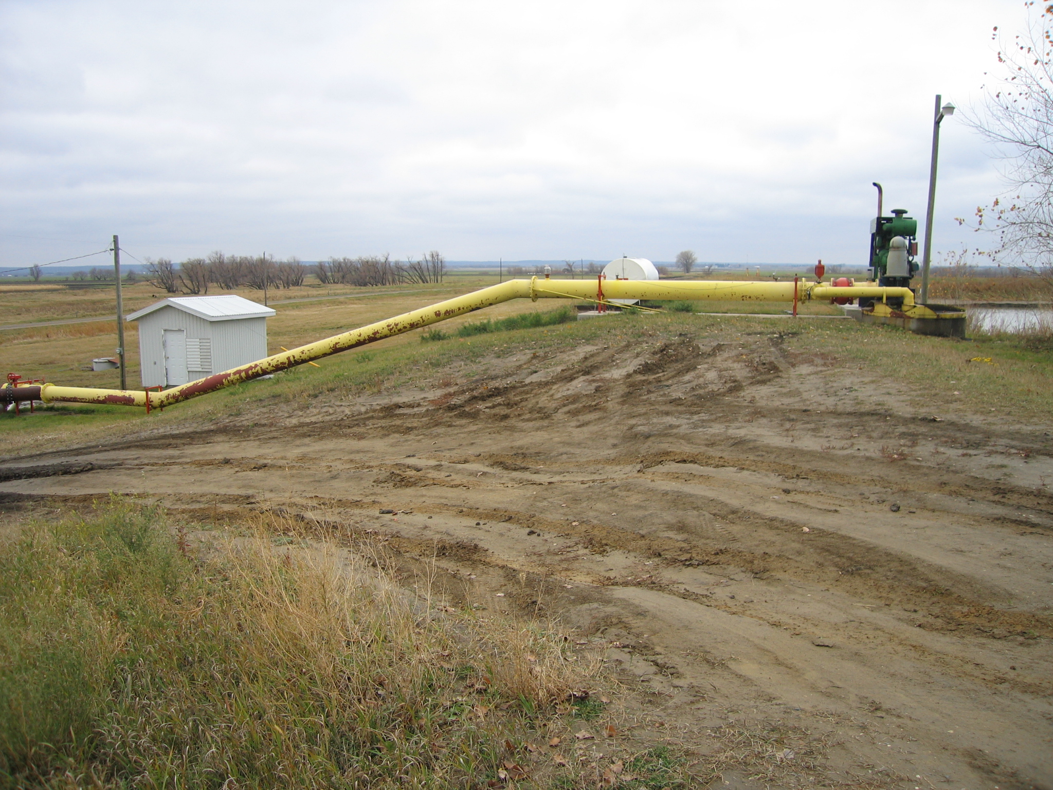
- pipes for filling and emptying the reservoir are placed over top of the berms (Figure 8). If the pipes need to be buried into the berms, place them well above the high-water level of the reservoir, otherwise they create a potential seepage path. Pipes through the berm and below the high-water mark are possible but should be designed by a professional engineer.
Design variables for a combination storage type reservoir (Figures 9 and 10) include:
- a reservoir depth that is 3–6 m below normal ground level (excavated depth)
- a berm height that is 4–6 m above normal ground level (>3 m should be designed by a professional engineer)
- an interior slope inclination from 6:1 (for lower maintenance) to 3:1 (may require riprap or other face protection to resist wave action, especially in larger water surfaces)
- gentle slopes reduce erosion potential due to wave action and allow for better trafficability during construction
- wave action potential increases as the surface area of reservoir gets bigger
- an exterior slope from 4:1 for easier slope maintenance to 2.5:1 for minimum land usage
Construction
Even the best design is only as good as the construction practices used when building the water reservoir. Request quotes from at least three contractors, view their work and get referrals. Consider the contractors experience, professional qualifications and specialized equipment. Place value on companies who have an engineering technician who supervises/inspects the construction. The following are key factors in the successful construction of a water reservoir (Figure 11).
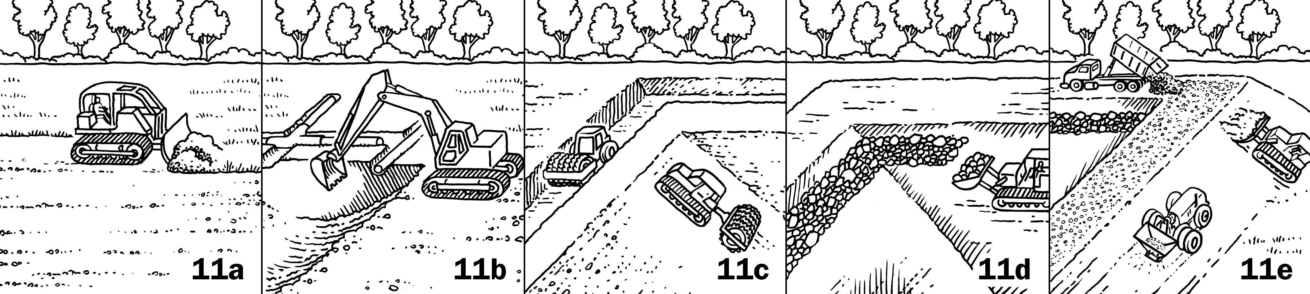
Site preparation — All of the topsoil must be removed (Figure 11a) and stockpiled for later use. It is especially important to remove the topsoil at the location of the berm. Otherwise, a seepage line could easily develop and weaken the structural integrity of the berm and potentially cause full failure. It is beneficial to save all the topsoil, as it is a valuable product and will be used to dress the top and slopes of berms. This allows for the establishment of erosion-resistant grass.
Subsurface drainage — Locate, remove and reroute all subsurface drainpipes around the reservoir site, especially from under the location of the berms (Figure 11b).
Equipment — Using proper equipment is important as large amounts of soil need to be excavated, moved, layered and properly compacted. Select a contractor who demonstrates experience and expertise in this type of reservoir construction and can implement the design, especially the berms.
Compaction — Starting with the key trench, place clay soil in layers 150–300 mm thick. Individually compact each layer (Figure 11c). The clay must have the optimum moisture; this is confirmed by in-situ or laboratory tests done by the contractor, technician or engineer. The objective is to compact and smear the soil structure to create a relatively impervious soil to avoid any potential for seepage.
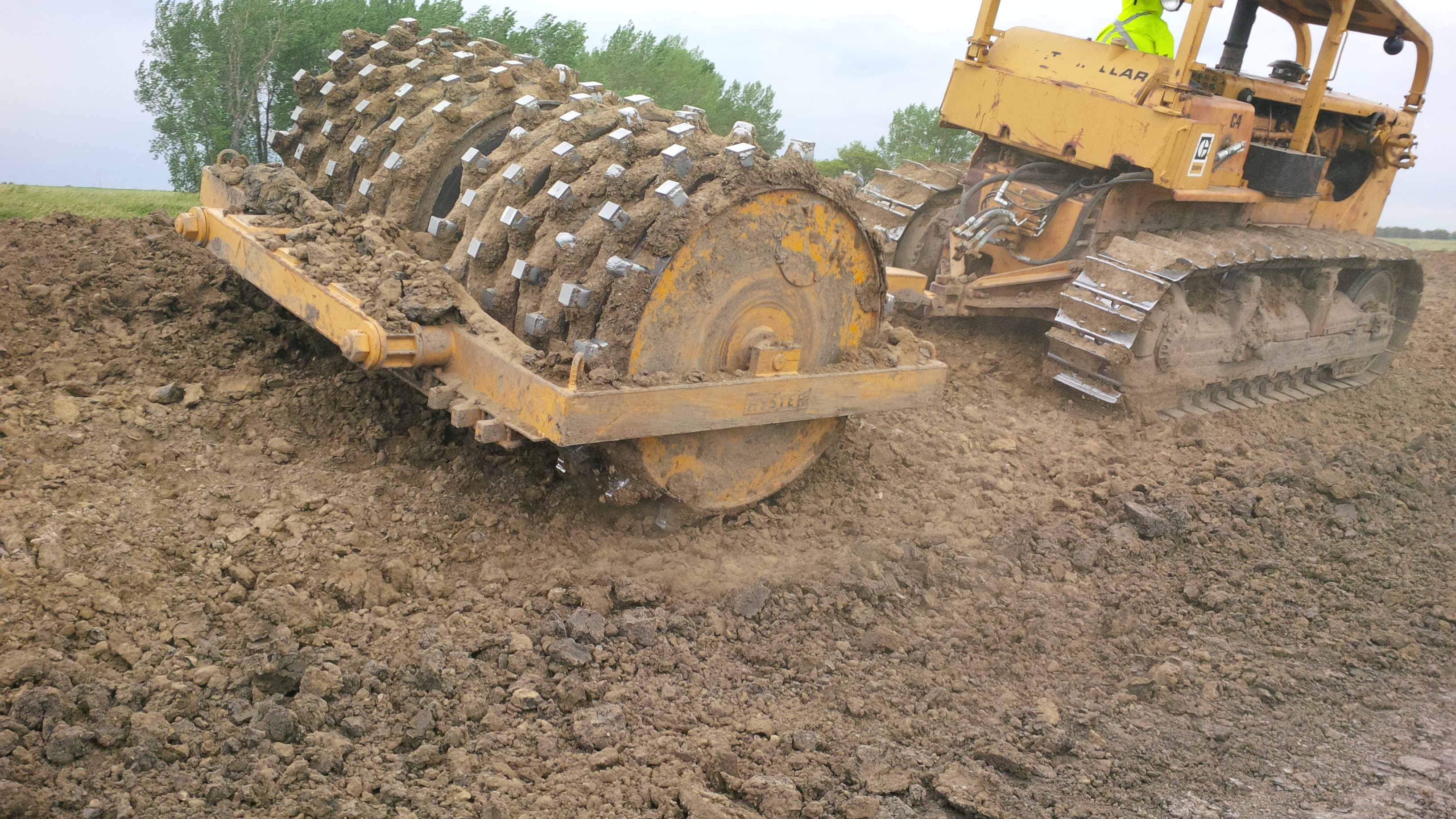
Compaction is achieved with specialized equipment, such as a “sheepsfoot” or “footed drum” (Figure 12). Simply tracking with a bulldozer is not efficient and does not provide enough compaction. As the soil layers are built up and compressed, testing equipment can measure the density to ensure that compaction achieves the desired strength according to the design. Usually, 10 or more passes over the entire surface of each layer with the mechanical compactors, when the soil is at optimum moisture, will achieve the desired soil density.
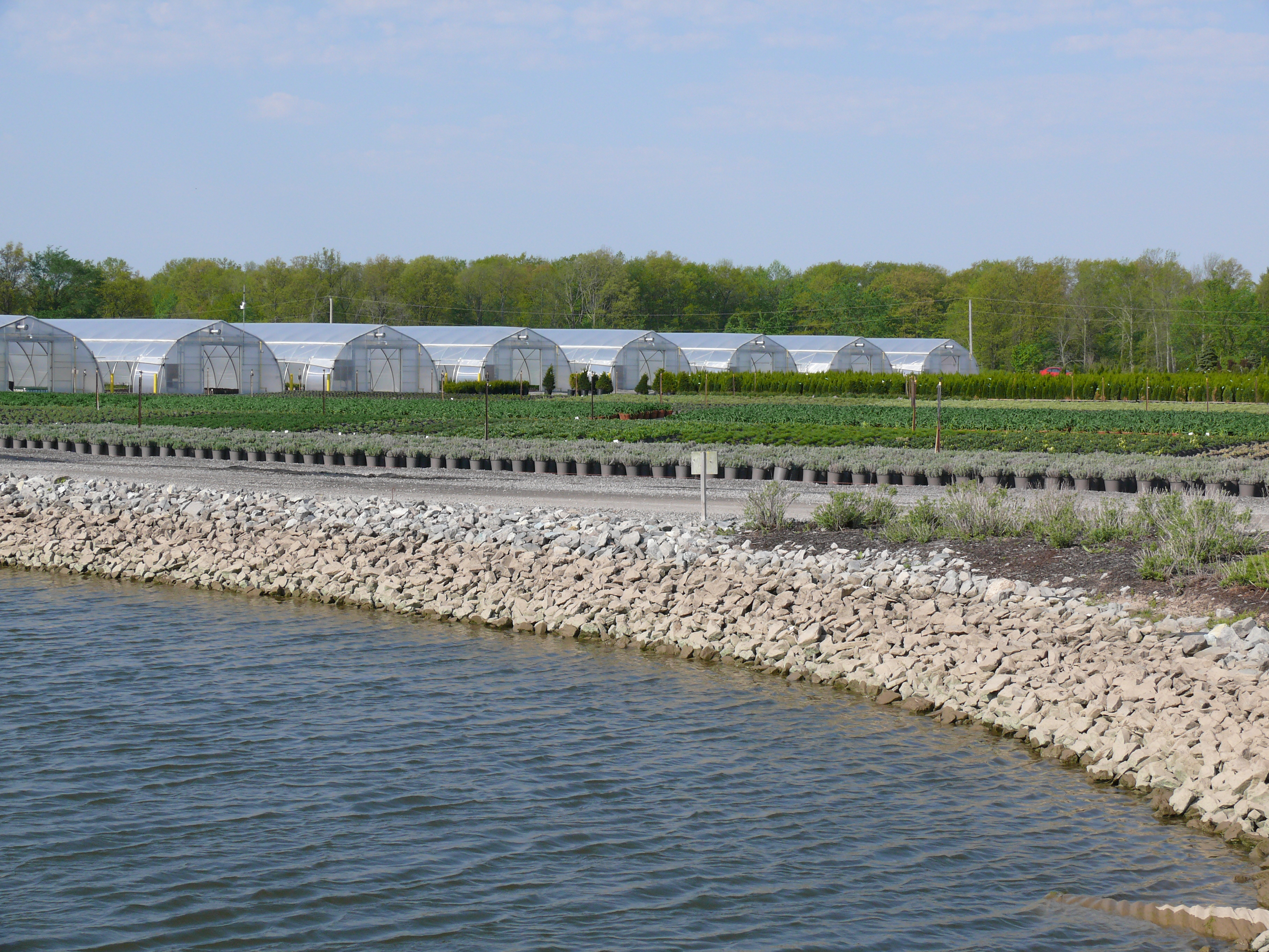
Erosion control — The need for erosion protection at the waterline is not always clear. Flatter slopes do not always need protection with rock riprap. Protection is needed when the reservoir is kept full for most of the year. Since the main purpose is to provide a water supply for irrigation, the reservoir may not be full for long stretches of time, which could reduce the need for additional erosion protection. If rock riprap is used, it should always be underlain with a geotextile filter cloth (Figure 11d). The filter cloth keeps the soil in place, and the rock riprap keeps the filter cloth in place while also providing protection from ice and waves (Figures 13 and 14).
Groundwater — If groundwater is a problem near the berms, it should have been identified by the soil tests and provided for in the design. A perimeter drainpipe is often used to correct this situation.
Seeding — Once the berms are completed, top-dress the top and side slopes with a layer of topsoil and seed with a grass mixture within 24 hours, before the soil dries out (Figure 11e and Figure 15). Choose a seed mixture that is drought tolerant and does not require mowing such as tall or creeping red fescue. Straw mulch, lightly spread, may help with early seedling establishment.
Traffic — The top of the berm is often graveled to provide an all-weather access road (Figure 11e).
Inspection and maintenance
Inspect the reservoir on a regular schedule. Inspection in the spring (full) and fall (low) is a minimum. More frequent inspections should be done if there is any indication of damage or seepage.
Develop an inspection checklist and record of maintenance activities that will provide a historical record for review (Table 3). A checklist will also demonstrate due diligence on the part of the operator. Timely maintenance, based on regular inspections, can address concerns in a cost-effective manner, before they develop into serious problems (Figure 16).
Inspection and Maintenance Checklist
- Cracking or settling of the berms
- Wet or soggy conditions at the berm toe
- Stability of interior and exterior side slopes
- Excessive erosion or sedimentation in or near the reservoir
- Woody vegetation in or on the berms
- Animal holes
- Obstructions of the inlet or outlet devices by trash and debris
- Deterioration of irrigation intake or pipes
Soil cracking
Soil cracking is often the result of the soil settling due to inadequate compaction or foundation compression. Soil cracking parallel to the crest of the berm reduces soil strength and the slope factor of safety, which could result in a slope failure depending on site-specific conditions. Soil cracking perpendicular to the crest of the berm may allow for seepage along the crack, again resulting in slope failure.
It is not easy to repair cracks. Although filling in the crack with clay helps to prevent water from entering or traveling along the crack, the effectiveness is limited. The water level in the reservoir may have to be reduced and/or the berm may need to be rebuilt.
Seepage
Water seepage reduces the safety factor of the slope and may cause slope failure. Seepage areas are identified by the presence of standing water, continuous wet conditions, water-loving vegetation and sometimes soil slumping.
Measures to lessen seepage problems post-construction are generally costly and are best prevented with proper initial design and construction techniques.
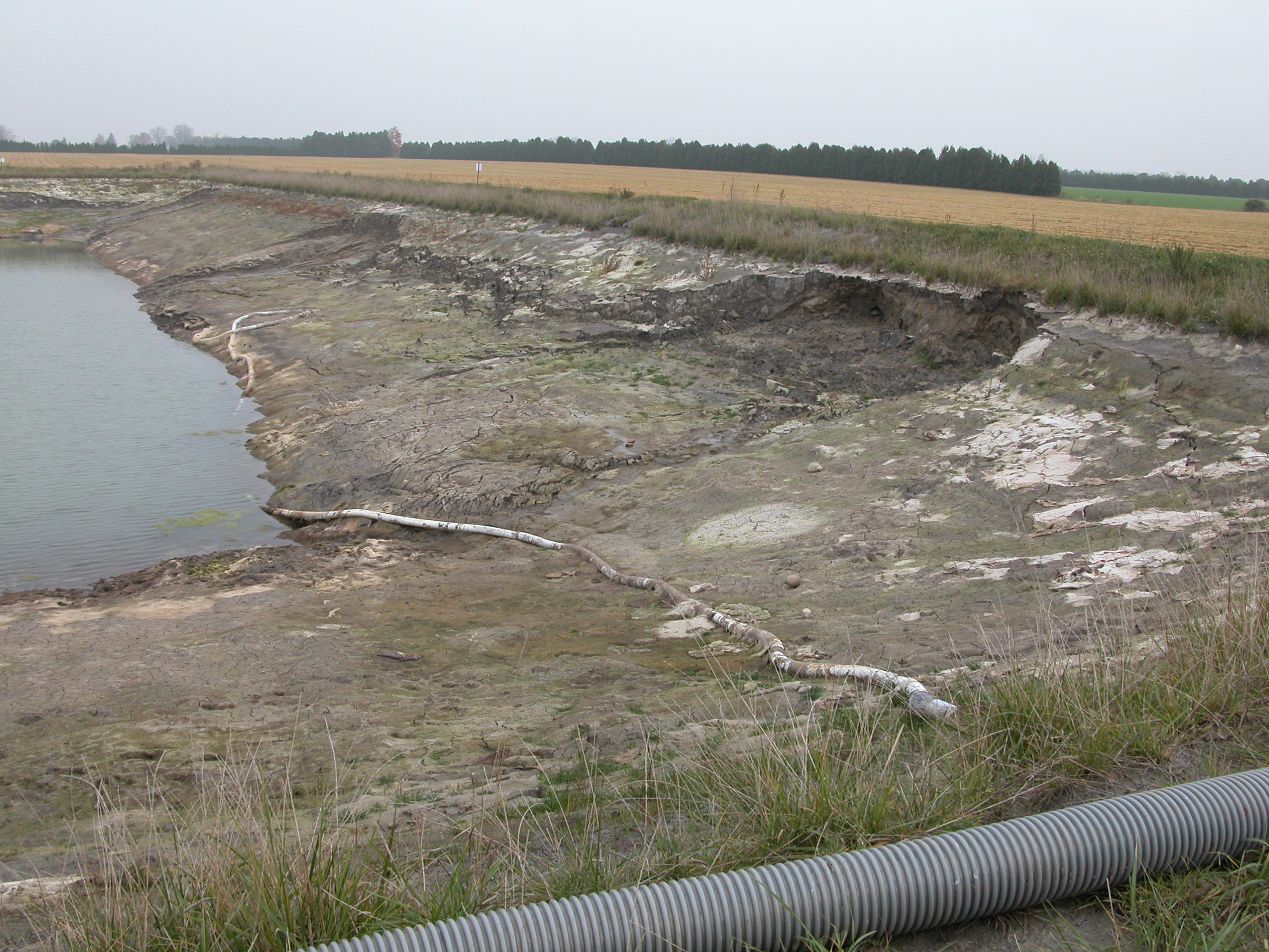
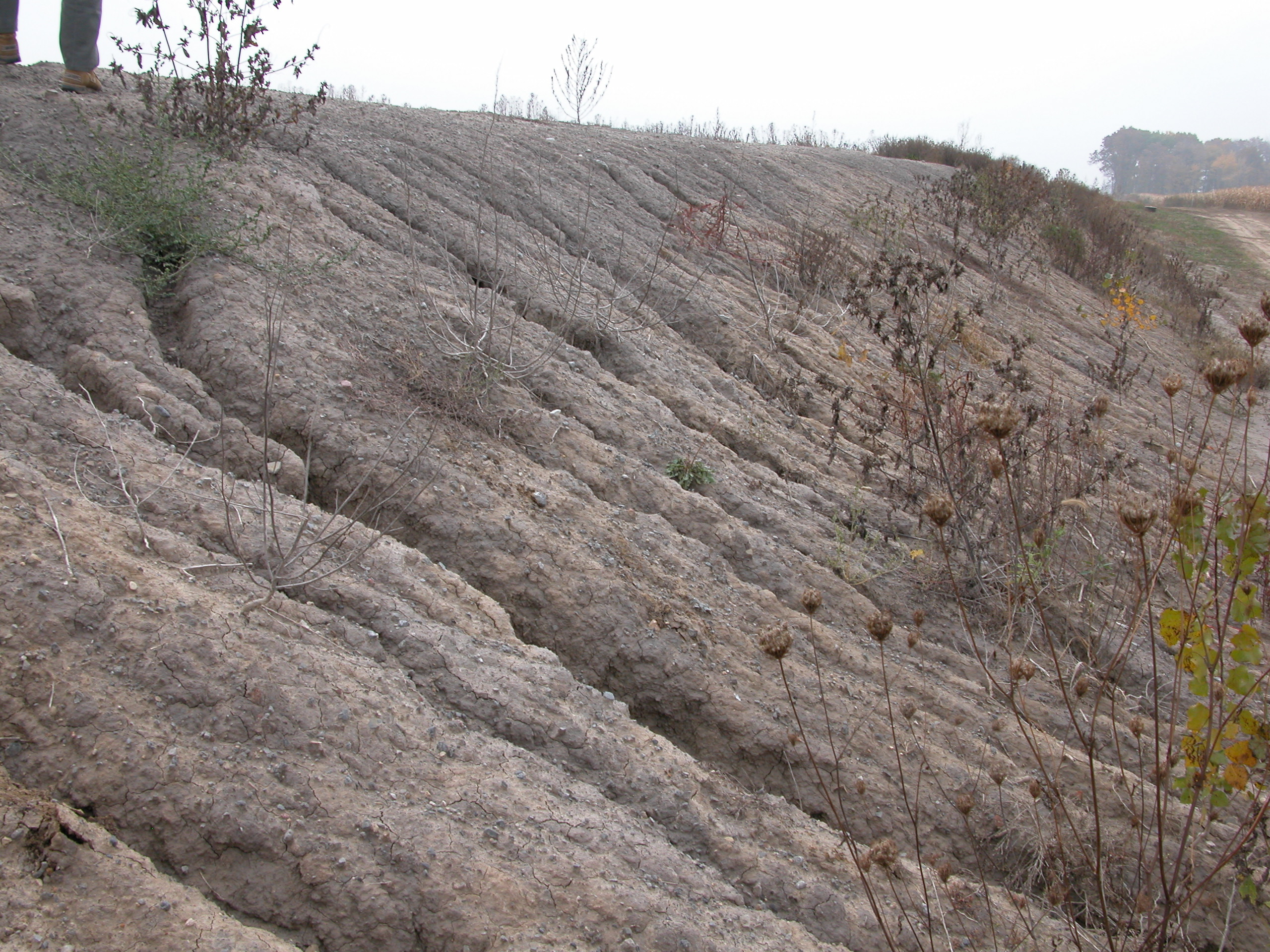
Erosion
Erosion can threaten the integrity of the berm. Seeding exposed slopes with a low-maintenance grass mixture is a normal part of construction to help prevent erosion before it begins. Repair eroded areas promptly as a normal part of maintenance, before they develop into a serious problem (Figure 17).
Organic material
Sediment accumulation in the reservoir will depend on the type of material, the side slopes and the deposition of organic material such as leaves. Organic material entering the reservoir will build up over time and, as it breaks down, can impair the quality of the water. Eventually, if enough organics get into a reservoir, a cleanout may be required.
Unwanted vegetation and animals
Do not allow woody vegetation to grow on berms as, over time, roots can weaken the berm.
Discourage burrowing animals from developing homes on the berm slopes. Fill any holes.
Mowing
Mow exterior slopes regularly unless a short grass has been seeded.
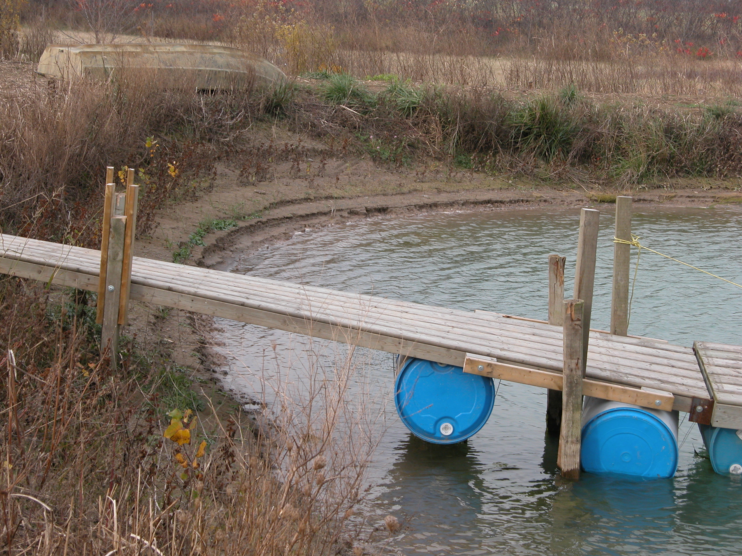
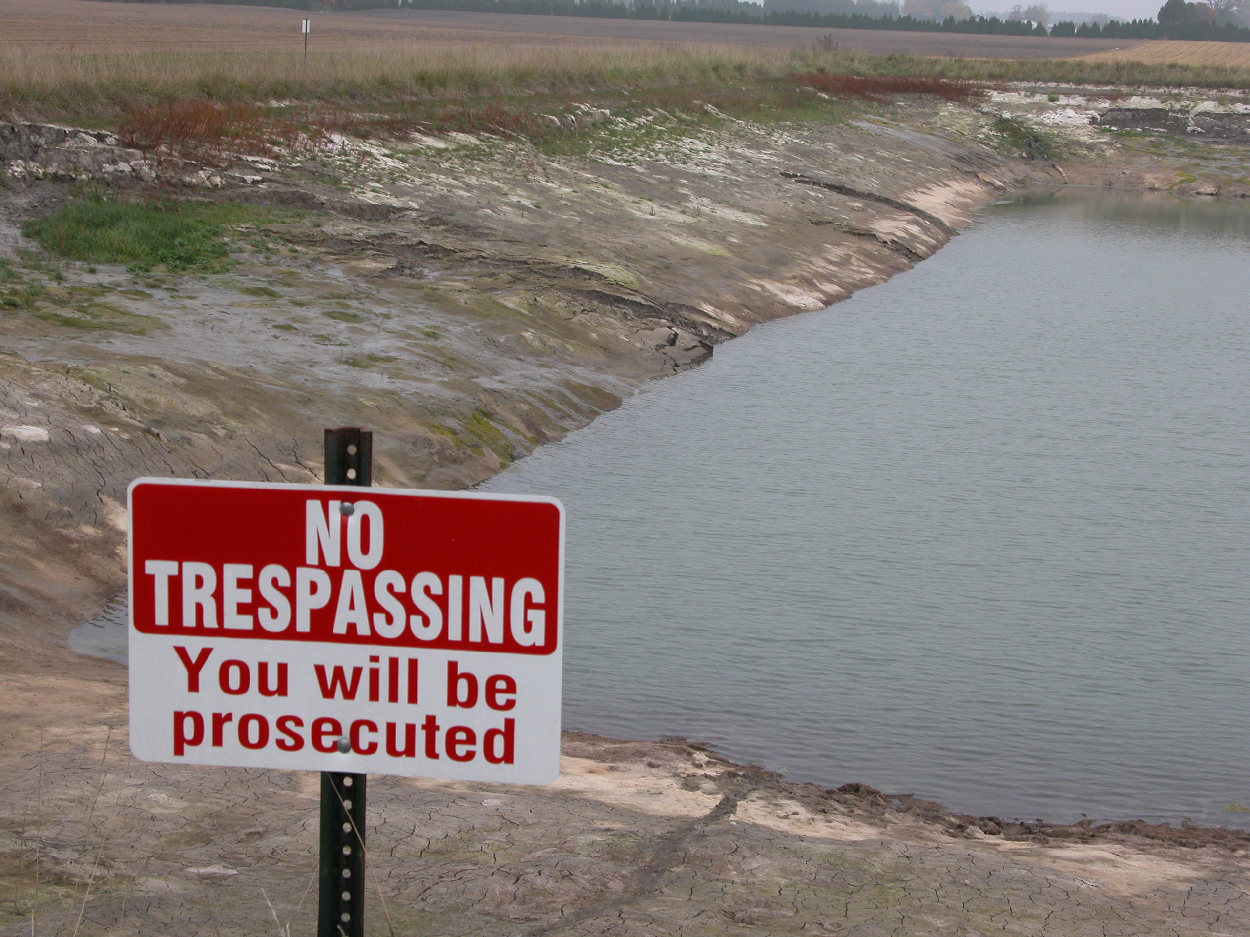
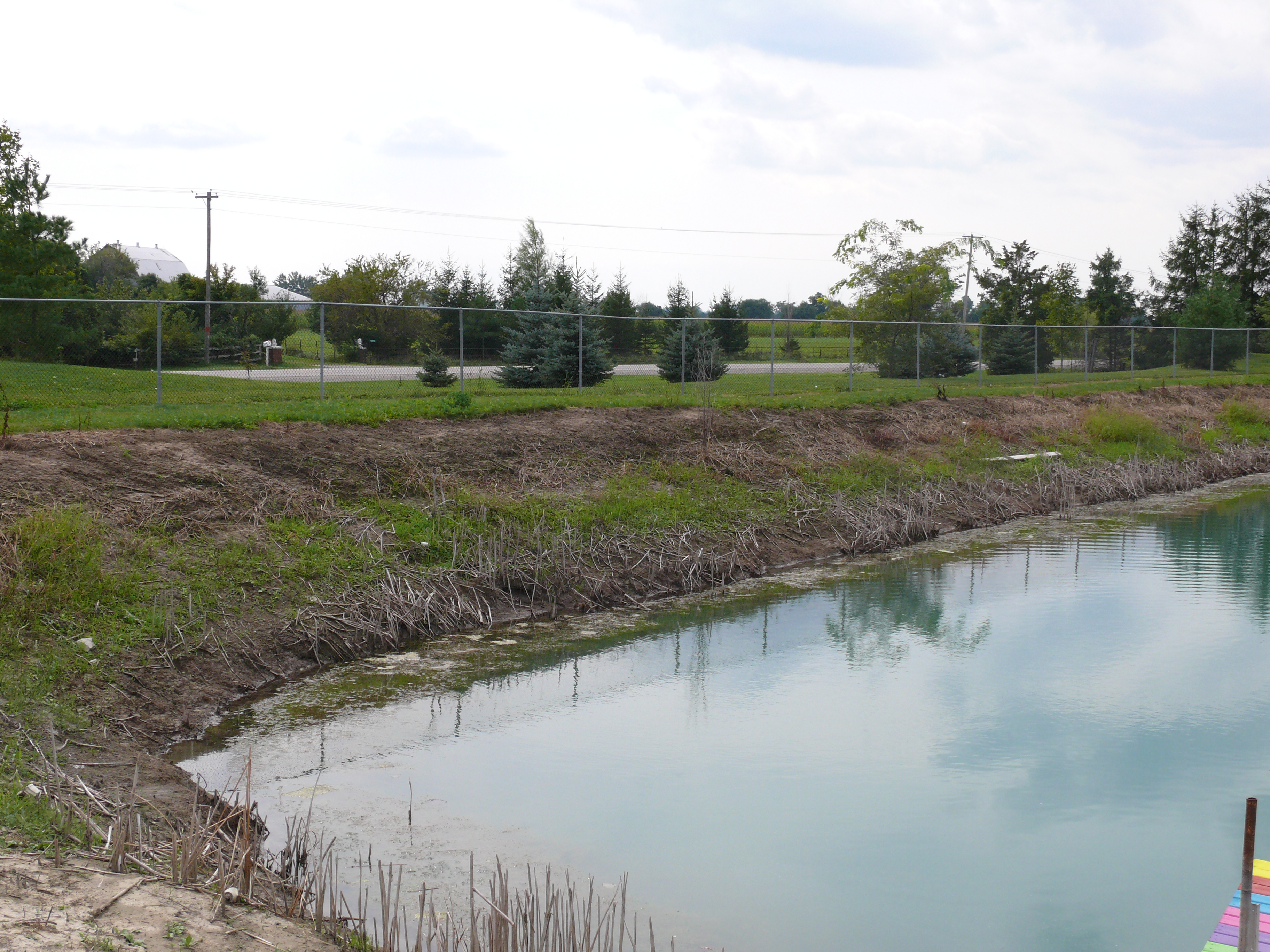
Safety
Each reservoir site location is unique and should be assessed for safety considerations. Remember that ponds are intriguing structures to children. Equip the site with the basic signage warnings and rescue equipment, such as a rope, a life buoy, a flotation device, etc. (Figure 18). Consider installing a safety fence around the entire reservoir (Figure 19). Check with the local municipality about reservoir safety requirements (fencing, etc.) and by-laws.
Regulations
Plan ahead — at least 12 months — to ensure that all the necessary permits are obtained prior to the construction of the reservoir. First, contact the local Conservation Authority (CA) as they can advise which permits are needed for the proposed location and where to get them.
The following permits may be required:
- Construction in a designated floodplain, near a river, creek or stream, requires a permit for construction from the local CA. The CA can advise whether the proposed reservoir site is in a designated area.
- A Permit to Take Water will be needed, both for filling the reservoir from an outside source and for pumping water from the reservoir during irrigation. Any time water is used from any source, including a river, creek, water well, pond, tile drain or other source, at a rate greater than 50,000 litres per day, a permit is required. Application is made to the Ontario Ministry of Environment, Conservation and Parks (MOECP). Contact an MOECC office.
In some reservoir construction projects, there is excess fill. To remove excavated fill from the property, a permit is required from the Ministry of Natural Resources (MNR) under the Aggregate Resources Act, 1990. In some cases, a letter from the Ontario Ministry of Agriculture, Food and Rural Affairs confirming the agricultural use of the reservoir may be required. Contact the local MNR office for more information.
Conclusion
Design and construction according to sound engineering principles and guidelines will minimize seepage and provide a stable, long-lasting, safe water reservoir. Irrigation reservoirs can provide the water supply needed for farm irrigation. Farm production systems and the environment will benefit from a irrigation reservoir combined with a small water source (such as a low yielding well or winter/spring pumping of a stream or drainage system).
This factsheet was written by Rebecca Shortt, P.Eng., water quantity engineer, OMAFRA, Simcoe, Shelby Jones, EIT, agricultural technician, OMAFRA, Simcoe, Patrick Handyside, P.Eng., water management engineer, AAFC, Sonja Fransen, P.Eng., water management engineer, AAFC with contributions from Vic Klassen, P.Eng., AAFC, Wade Morrison, P.Eng., AAFC and Jim Myslik, P.Eng. (retired).