Evaluating Construction Activities Impacting on Water Resources Part III B - Handbook for Dredging
The aim of this Ministry of Environment handbook is to provide an overview of the management options for the handling of dredged material in the Province of Ontario. These guidelines were developed to protect the receiving environment according to the physical, chemical and biological quality of the material being dredged
Report prepared by:
Standards Development Branch
Ontario Ministry of the Environment
February 1991
Revised February 1994
Updated January 2011
Foreword
In 1976, the Ontario Ministry of Environment (OMOE) published the guideline “Evaluating Construction Activities Impacting on Water Resources” as an aid in the assessment of the environmental impact of construction activities. The document was subsequently updated in 1984 and 1995.
The revised guidelines have been divided into five parts, as follows:
- Part I: Guidelines for construction of hydrocarbon transmission and distribution pipelines crossing water courses (March 1984)
- Part II: Guidelines for construction of highways and bridges (March 1984)
- Part III: Handbook for dredging and dredged material disposal in Ontario A, B, C
- Legislation, Policies, Sediment Classification & Disposal
- Dredging, Transport and Monitoring
- Sediment Sampling and Laboratory Analysis
- Part IV: Guidelines for marine construction projects (April 1986)
- Part V: Guidelines for small-scale waterfront projects (April 1986)
In 1995, Parts I, II, IV and V were revised again to reflect more recent approaches to sediment and erosion control and were consolidated into one document entitled “Guidelines for Evaluation Construction Activities Impacting on Water Resources” (1995). Part III continues to be available separately.
In 2011, minor modifications were made to this handbook to update sections with current information (e.g. update references to legislation, policies, agencies, etc.). However, no changes were made to direction or guidance provided in this document.
This handbook (Dredging and Dredged Material Disposal - Part III) has been prepared to assist dredging project proponents, OMOE staff and staff of other regulatory agencies in the selection of safe and appropriate management methods based on dredged material characteristics and current OMOE legislation. This document is intended to be a reference handbook of dredging-disposal activities, the details of which may not be required on a routine basis. The current revision incorporates the new sediment evaluation procedures from the ministry document entitled, “Guidelines for Identifying, Assessing and Managing Contaminated Sediments in Ontario: An Integrated Approach” (OMOE, 2008) which replaces the Provincial Sediment Quality Guidelines (Persaud et al. 1992).
Mention of trade names and commercial products in this handbook does not constitute endorsement.
Acknowledgements
The preliminary report was originally prepared under contract by Beak Consultants and Ocean Chem Group.
This report underwent review and consequently many modifications were made based on valuable comments from the following people: Dredged Material Management Working Group, Steve Maude, Gerry Myslik, Archie McLarty, Duncan Boyd, Deo Persaud, Wolfgang Scheider, John Ralston, Tammy Lomas, Don King, Ian Carter and Elizabeth Pastorek from the Ontario Ministry of the Environment, and Ian Orchard, Laurie Sarazin, John Marsden, Susan Humphrey, Simon Llewllyn, Alfred Chau, Peter Fowlie and Bill Lee from Environment Canada.
Tammy Lomas and Stephen Petro of the Water Resources Branch, Ontario Ministry of the Environment coordinated editorial revisions to the report.
Special thanks to Rose-Marie Gonsalves of the Water Resources Branch, Ontario Ministry of the Environment for her endurance in typing the many editorial revisions.
Volume III of the Ontario Ministry of Environment’s Report-Evaluating Construction Activities Impacting on Water Resources was supported in part by funds received from Environment Canada under terms of the Canada-Ontario Agreement (COA) on Great Lakes Water Quality. Activities are coordinated with those of the Federal Government under the guidance of the COA Polluted Sediments Committee.
The revisions made to this document in 2011 were coordinated by staff in the Ontario Ministry of the Environment’s Eastern Region with the assistance and expertise from staff from the Ontario Ministry of the Environment’s Environmental Monitoring and Reporting Branch, Standards Development Branch, Operations Division (Technical Support Section), and Legal Services Branch.
Introduction
Environmentally sound marine construction practice requires that every effort be made to preserve the physical and biological integrity of Ontario’s waterbodies in accordance with the provincial goals - “To ensure that the surface waters of the Province are of a quality which is satisfactory for aquatic life and recreation” (Ontario Ministry of the Environment, 1994).
The aim of this Ministry of Environment handbook is to provide an overview of the management options for the handling of dredged material in the Province of Ontario. These guidelines were developed to protect the receiving environment according to the physical, chemical and biological quality of the material being dredged. Recognition is given, where appropriate, to the potential re-use of certain materials.
This document is not intended to provide legal advice and it should not be construed as such. The relevant and applicable legislation should be reviewed and considered before proceeding with a project. Updates and amendments to legislation can be accessed through the e-Laws web site.
Dredging for the purposes of this handbook is identified as the planned, mechanical movement of material located below the surface of a waterbody, or at the land/water interface. These guidelines apply to all forms of dredging.
The following sections review the use of a variety of dredges, transport of dredged material and monitoring of dredging operations. The following sections are not exhaustive and are intended for informational purposes only. Additional information is available through a variety of sources such as the US Army Corps of Engineers web site and the Great Lakes Commission (Great Lakes Dredging Team web site).
Dredging and Transport of Dredged Material (1.0)
Dredges and Their Operation (1.1)
Dredges may be grouped into two broad categories, mechanical and hydraulic. Mechanical dredges use one or more buckets of various designs to pick up the material to be dredged. The material is typically placed in a scow or barge and transported to a disposal site. Hydraulic dredges act like a large vacuum cleaner. They may or may not employ a cutter head at the suction inlet to loosen the material. A pump and pipeline system is normally used to move the dredged material as a slurry.
Mechanical Dredges (1.1.1)
Mechanical dredges are similar in operation to their dry land counterparts. Material is picked up in the dredge bucket and either placed in the disposal area or may be transported. The latter by trucks, scows/barges or occasionally conveyor belts. In some instances, the dredge and transport scow are combined as one vessel, particularly where it is necessary to mechanically off-load the scow. Differences in operation of the various dredges are dictated by the physical nature of the material to be dredged.
Ladder bucket dredges (Figure 1.1) are derived from some of the earliest known dredges and are still commonly used in some European harbours and mining operations.
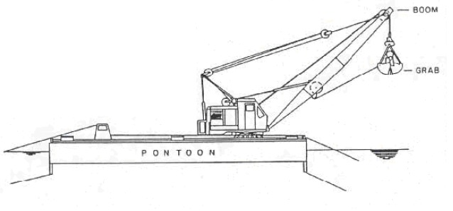
Clamshell dredges (Figure 1.2) are among the most versatile dredge buckets in that they are able to work in all types of material including blasted rock, and maneuverable enough to work in restricted areas. Clamshell dredges have been typically used in both capital and maintenance projects in Small Craft Harbour facilities. The downward digging force that can be exerted by the bucket is limited by its static or dropping weight. Various bucket and jaw designs are available to cope with a variety of bottom materials from soft mud to blasted rock. Dredging depth is limited only by the amount of wire rope on the winch drums. Clamshell dredges leave a somewhat irregular bottom profile such that dredging is often necessary to ensure high spots are not left above the desired depth.
The dragline dredge, (Figure 1.3) using wire ropes from the top and base of the boom to the bucket, casts the bucket forward and then pulls the bucket back through the material to be excavated. Digging force is a function of the bucket weight, the winching force and the relative slope of the excavation face to the bucket. The bucket is merely a scoop with no moving parts so that it cannot close around the load. When working with non- cohesive materials or in substantial water depths, this becomes a disadvantage due to washout. It is frequently used in small scale dredging operations of coarse sand or cobble which can be performed from shore, and where the materials will be disposed in the near-shore area.
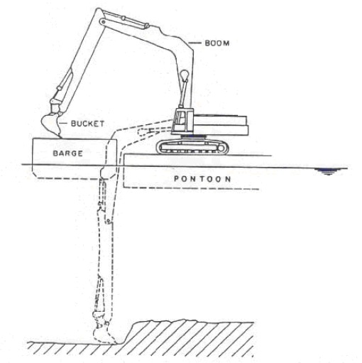
Backhoe or dipper dredges (Figure 1.4) combine the agility of the clamshell and the digging force of the power shovel. The load is scooped back and up into the digging face with a semi-open bucket on an articulating boom. The excavation depth is limited by the reach of the boom. More control over the bucket is possible than with a dragline, and spillage is typically less. Backhoes are now used more commonly because of their greater digging force compared to clamshells and draglines.
The various mechanical dredges pick up bottom sediments without substantially affecting their in-place density, i.e., without entraining excess water. The dredged materials may be deposited by the dredge directly at an aquatic or on-land disposal site within reach of the boom. More often than not, the disposal site is farther away and an intermediate transport mode is required. For dredges working close to a dock or shoreline, it may be possible to load directly into trucks. This would normally be appropriate only for relatively small quantities of sediment destined for up-land disposal. Sealed truck bodies are required to avoid material loss/leakage along the haulage route. Transport from a mechanical dredge working in open water is typically undertaken by tug-powered or self-propelled barges. Most such barges are designed to dump their load at an open water disposal site through bottom doors or by splitting open along a longitudinal hinge line.
Figure 1.1: Ladder Bucket Dredge
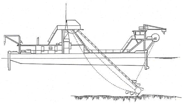
Figure 1.2: Clamshell Dredge
Tug and barge combinations and self-propelled barges are typically restricted in their operations because of sea state (i.e., wave conditions). Placement of material from barges into a confined disposal facility requires re-handling. Special dredging equipment has been developed for specific uses. One example is the use of a modified scow to precisely place dredged granular material as backfill over a deep water pipeline through a pipe suspended vertically from the ship to the bottom and guided by a computer-controlled dynamic positioning system.
Hydraulic Dredges (1.1.2)
Hydraulic dredges pump sediment as a slurry, typically with 5-20% solids content. Dredged material is transported from the suction dredge via a pipeline directly to the disposal area.
Booster pumps can be added to the pipeline to extend the operating distance between the dredge site and the disposal site. Transport distances of 1 to 10 km have been reported.
In a cutter suction dredge (Figure 1.5), the use of a cutter head augments the efficiency and usability (broader sediment classification) of the suction-only dredge. Sizes (given by the diameter of the pump discharge line) vary from small 6inches (152 mm) models up to 36 inches (914 mm) dredges with the capacity to excavate 3,000 cubic metres per hour.
In operation, the cutter suction dredge has anchors placed ahead to either side and a lowered spud at the stern. Winches to the anchors pivot the dredge on the rear spud describing an arc-shaped cut. At the end of the cut, the alternate spud is lowered, the first spud raised and the dredge is swung back in the opposite direction “walking” forward as it makes the next cut. These dredges typically rely on the skill of the operator to maximize production without plugging the pipeline. Mobilization and demobilization take some time (and expense) so that the equipment is seldom appropriate for small scale projects.
The power driven cutter head allows a cutter suction dredge to work in practically any type of material but rock. Very large dredges may have 1,500 horse power (1,118 kw) on the cutter and 5,000 horse power (3,724 kw) on the pump.
For smaller projects, such as lake restoration, dredging of canals/ channels or removal of weed infestations, small truck-transportable dredges are used. An example of this type of dredge is the Mud Cat (Figure 1.6).
Figure 1.3: Dragline Dredge
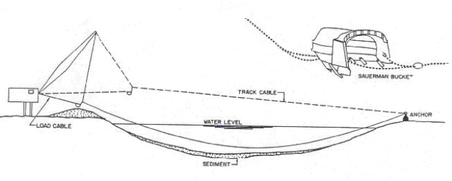
Figure 1.4: Backhoe Dredge
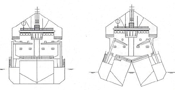
The trailing suction hopper dredge is particularly useful for the removal of unconsolidated sand or mud in channels (Figure 1.7). These self-contained ships pump the dredged material aboard through a trailing suction pipe (or pipes) equipped with a draghead which loosens the material and directs it into the suction inlet as the vessel moves ahead. In normal operation, the hoppers are surcharged until an economic load is obtained (perhaps 50% solids) with excess water and fines being discharged overboard. (Additional discussion on “overflow” can be found in Section 2.0). Typically, these vessels are self- contained and combine the dredging and transport functions. Modern dredges are equipped with swell compensators on the suction pipe which allow operation even in 35 knot winds. The distance to the disposal site is limited only by the economics of vessel turnaround time, not by physical constraints or weather considerations. Hopper dredges are able to discharge their load by dumping through hopper doors, using the split hull version (Figure 1.8), or by pumping into a confined shoreline disposal facility.
The dustpan dredge is a hydraulic suction dredge with a special suction head shaped like a dustpan developed to quickly remove shoals. Across the opening are arranged vertical pipes which jet water to loosen sand and silt. Dustpan dredges operate by winching themselves upstream into the shoal to be removed. The wide head and the high pressure water jets make it possible to obtain higher solids content in freely flowing materials than with other hydraulic suction dredges. This type of dredge has been successfully tested on removal of Kepone-contaminated sediments from the James River (Vann, 1981).
Rather than the centrifugal pump powering the suction hopper and cutter suction dredges, the Pneuma dredge (Figure 1.9) pump body comprises two or three pressure cylinders acting as a piston pump with compressed air taking the place of the piston. The unit is compact and portable, lending itself to mobile operations from a small barge or a land-based crane. In free flowing sediments, the pump inlets are simply lowered into the deposit. In more cohesive materials, scoops (if required, incorporating a cutter head) are mounted to the pump body to feed loosened material to the suction inlet and the assembly is winched through the deposit. Material is pumped as a high solids slurry through the discharge line to a disposal facility. For short distances, the system is claimed to have a high solids delivery (up to 70%).
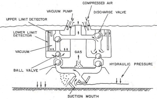
The Oozer system (Figure 1.10) is a special purpose dredge developed in Japan to remove highly contaminated soft or “soupy” sediment without losses to the water column. The unit is reportedly difficult and expensive to use. The volume dredged per unit time is relatively low. Sediment is lifted with compressed air and vacuum pumps.
Figure 1.5: Cutter Suction Dredge
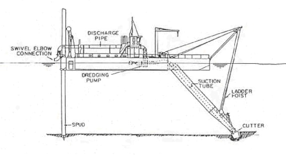
Figure 1.6: Mud Cat Dredge
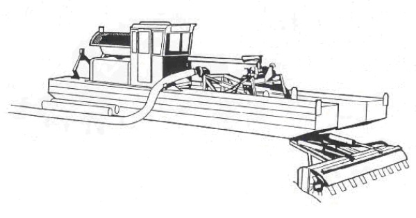
Figure 1.7: Trailing Suction Hopper Dredge
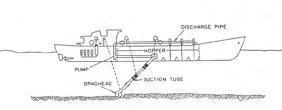
Figure 1.8: Operation of a Split-Hull Trailing Suction Hopper Dredge
Disposal Operations and Equipment Choice (1.2)
Selection of a disposal alternative is determined by project purpose, economics and the physical, chemical and biological properties of the dredged material.
Economics favour unconfined open water disposal. This can be accomplished by any of the dredge types previously described. The mechanical dredges place the sediment within reach of their booms or load barges for hauls to more distant disposal sites. Cutter suction dredges can pump material through a floating pipeline. Trailing suction hopper dredges have the greatest range for transporting materials to a remote open water site. A variation of the trailing suction dredge discharges the material directly overboard at the dredge site via a long boom (side-casting). For small scale projects, particularly where the dredging is being done by a land-based dragline or clamshell, economics favour local on-land disposal directly or via trucks.
On-shore or near-shore disposal may be dictated by the desire to improve or create additional land for industrial, commercial, residential, recreational or habitat purposes. The land use will determine the disposal location and configuration. Unless the area to be filled is within reach of the dredge site, mechanical dredges require a re-handling operation to move material into upland disposal sites from the transport barge. Cutter suction dredges have the advantage of being able to pump material directly to shoreline or upland sites within the range of their pumps (which can be extended by booster pumps). Most hopper dredges also can now pump material ashore.
Environmental Impacts of Dredging and Transport of Dredged Materials to the Disposal Site (1.3)
Dredging operations may be divided into three steps: dredging, transport and disposal. The impacts at each step will be a function of the existing environment affected, the nature of the material being dredged and the type of equipment selected to do the work.
Capital dredging is defined as “new” work; that is, the removal of material from an area that has not been previously dredged, e.g., deepening and widening a navigational channel. Maintenance dredging is dredging required to maintain navigational access or depth. Typically, maintenance dredging involves removal of recently deposited sediment brought into the site by long-shore transport or by rivers. Because contaminants are preferentially associated with fine-grained sediments, maintenance dredging typically involves the removal of more contaminated sediments than capital dredging.
Figure 1.9: Operating Principle of the Pneuma Dredge System
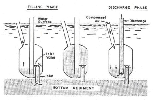
Figure 1.10: Oozer Pump Operation (From Koba and Shiba, 1981)
The degree to which environmental problems occur at a given site is primarily a function of the disturbance and sediment loss created by the operation of the dredge. Although it is often beyond the control of the environmental manager, skilled operation of the correct equipment for the conditions encountered will reduce environmental impact as well as increase efficiency.
As illustrated in Figure 1.11, sediment re-suspension is lowest with cutter suction dredges or suction hopper dredges operated without overflow. In unconsolidated fine- grained sediments, clamshell dredges generate turbidity levels comparable to overflowing hopper dredges. Figure 1.12 schematically presents the two extremes of turbidity encountered in a water body. Natural conditions refer to the minimum disturbance that can occur while storm conditions refer to the maximum turbidity that can be expected. The different dredges have been placed on this schematic to indicate the amount of turbidity generated by each dredge type. With a cutter suction dredge the sediment losses occur predominantly at the cutter head and may not appear in the surface waters. Hopper dredges lose some material at the trailing drag head, but a significant source of fines is the overflow at or near the surface. Propeller scour from a hopper dredge may result in re-suspension in shallow channels which may be comparable to that generated by ships of similar size. With a clamshell dredge, losses occur as the bucket cuts into the bottom material; as washout while the bucket is raised through the water column; and, as spillage when the bucket breaks the water surface and is swung to the dump scow. The disturbance from a backhoe dredge is comparable to that from the clamshell dredge. Dragline and bucket dredges are normally operated in coarse-grained material, where loss of fines is not a significant concern. In softer material, washout from the bucket would be comparable to that from a clamshell operation.
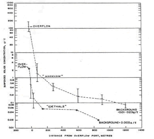
The areal extent of the impact at the dredge site will be strongly influenced by the presence or absence of currents. Bohlen et al. (1979) reported that the solids suspended during a river dredging operation typically re-settle within 500 to 1,000 m of the dredge. Koba and Shiba (1981) reported similar results for harbour dredging in Japan. In calm water the impact of stationary dredges will be restricted to a relatively small area. Suction hopper dredges will influence a larger area because of the distance it has to travel in loading the hoppers and especially the distance travelled during hopper overflow. Figure 1.13 illustrates the decrease in turbidity with distance from an overflow operation on a trailing suction hopper dredge.
Of the three steps - dredging, transport and disposal - transport of dredged sediment to the disposal site will have the lowest impact. Impacts of dredged material on the environment at this stage come about only through leaks or spills, whether the transport medium is a pipeline, scow, hopper dredge or truck. There may be impacts from secondary construction such as the construction of a haul road or re-handling facility or the dredging of an access channel for scows.
Figure 1.11: Areas of Sediment Re-suspension During Dredging (From USCE, San Francisco, 1977)
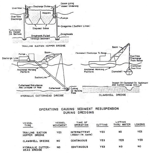
Figure 1.12: Relative Turbidity Caused by Different Types of Dredges (From Wakeman et al., 1975)
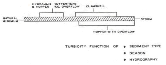
Figure 1.13: Relation Between Concentration of Suspended Solids in the Near-surface Overflow Plume and the Distance (in metres) Downstream of the Overflow Ports (From Barnard, 1978)
Mitigation Measures (1.4)
Successful application of mitigation measures depends on a thorough analysis of the dredge and dredged material disposal sites and an assessment of the proposed dredging operation. The following considerations should be included during this evaluation of potential impacts:
- proposed timing and duration of dredging;
- proposed methodology for dredging and dredge material disposal;
- the physical, chemical and biological properties of the sediment at both the dredge and disposal sites; physical characteristics of the watercourse, notably depth, currents and wave climate;
- quantity to be dredged;
- biotic environment (flora and fauna) at both sites including fish, bird and (where applicable) mammal habitat considerations;
- land and water use in the area, e.g. beach or industrial, presence of water intakes, riparian and waterlot rights;
- existing water quality at both sites; and
- past history of dredging and dredge material disposal in the area.
Scheduling can be an effective mitigation measure to avoid impacts on fish spawning, recreational use and water supplies. When possible, dredging should be carried out at periods of low biological activity and low streamflow (or lake currents).
Selection of the type and size of a dredge may be an appropriate mitigation measure. For lake restoration projects, hydraulic dredges have been selected for their ability to work without creating turbidity levels that would interfere with existing fish populations. By using too small a dredge, the project duration, with its attendant impacts, can be needlessly extended. The size of a hydraulic dredge must not exceed the capability of the disposal area to provide adequate retention. Typically, trailing suction hopper dredges “overflow” during operations to improve the density of the final load. In some cases or in consideration of the nature of the sediments, hopper overflow may not be permitted.
For highly contaminated sediments, where toxic materials could be transported off site via re-suspended sediment, it may be necessary to modify conventional dredges or employ special purpose equipment. The conventional clamshell bucket can be modified so that it is sealed upon closing to eliminate the spillage that normally occurs. Some experiments have been made with shrouds to enclose the clam shell (Raymond, 1983). The Mud Cat dredge (Figure 1.6), with its shrouded auger cutterhead, reportedly generates less turbidity than conventional cutterheads (Sherman, 1984).
The Pneuma (Figure 1.9) and Oozer (Figure 1.10) dredging systems are both reported to operate with minimal sediment re-suspension, and have been recommended for use with very fine-grained highly contaminated sediments.
To confine turbid surface water, silt curtains have been successfully deployed at both the dredging and the disposal area (Huston and Huston, 1976; JBF Scientific, 1978). The silt curtain is typically made of low permeability fabric suspended from a floating boom and weighted at the bottom. To be effective, the bottom of the curtain must rest on the sediment. Its effectiveness is also limited to areas with low currents (less than 1 knot) and limited wave action (generally less than 1 metre).
Management of Dredging Slurries (1.5)
Slurries, in the context of this guideline, are associated with hydraulic dredging operations. Hydraulic dredging in Ontario includes dredging for the purpose of removing excess sediments and for the extraction of mineral resources.
The hydraulic dredging procedure involves pumping the sediments in the form of a slurry. Within the context of the legislation administered by the Ontario Ministry of the Environment, hydraulic dredging is viewed as a process which takes water, contaminates it and then returns the water back to the watercourse. Both the taking of water and the treatment process required to remove the sediments from the slurry fall under the provisions of the Ontario Water Resources Act (OWRA). Accordingly, the Ontario Ministry of the Environment will regulate the taking of water and its release back to the natural environment.
Projects are divided into the following categories:
1. Resource Recovery Dredging
Hydraulic dredging operations being undertaken for the purpose of resource recovery under the Aggregate Resources Act are regulated by the Ontario Ministry of Natural Resources. For these projects, the concerns of the Ontario Ministry of the Environment are identified to the Ontario Ministry of Natural Resources.
2. Beach Nourishment
Use of hydraulically dredged sand for beach nourishment will be recognized by the Ontario Ministry of the Environment as a beneficial use of sediment providing that bulk chemical analyses results show that the sediment is acceptable for open water disposal. If such projects result in the taking of more than 50,000 litres per day of water, then an OWRA, Section 34 approval will be required for the water taking. The Permit to Take Water will specify the quantity and any conditions considered necessary and appropriate by the issuing Director. These projects may also require a Sewage Works Approval under section 53 of the OWRA which will specify any conditions considered necessary and appropriate by the issuing Director.
3. Private and Public Sector Hydraulic Dredging Projects
Hydraulic dredging projects undertaken by the private or public sectors may require an OWRA, Section 34 approval if the water taking exceeds 50,000 litre per day of water. The Permit to Take Water will specify the quantity and any conditions considered necessary and appropriate by the issuing Director.
These projects may also require a Sewage Works Approval under section 53 of the OWRA which will specify any conditions considered necessary and appropriate by the issuing Director.
Where a Sewage Works Approval is required, ultimate disposal of sediment will be in accordance with the classification process presented in Part III A of this report series.
Where the dredged material is not put to any specific use, the common procedure is to pump the slurry to a confined settling pond where the sediments are removed from the slurry by settling before the excess water is discharged back to the watercourse. Waste slurries from maintenance dredging of fine-grained sediments can contain suspended solids concentrations well in excess of 20,000 mg/l. At concentrations of this magnitude, an extremely efficient settling process is necessary to reduce the suspended solids to a level acceptable for discharge to the receiving waters.
Confined disposal facilities for dredged materials must provide sufficient capacity to retain the total volume of sediments being dredged, as well as adequate detention time for the sedimentation process to achieve an acceptable effluent quality.
Monitoring (2.0)
The following discussion covers points that might be required as part of the approval for dredging and disposal. Not all requirements may be implemented for every project (proponent should discuss with OMOE).
Dredging Operation (2.1)
There are three components of concern:
- turbidity generated during the operation;
- interference with navigation or other uses of the waterways; and
- interference with fish migrations or movements.
The type of dredging equipment used (see Section 1) and the nature of the material dredged are the determining factors in the generation of turbidity. The proponent may be required to monitor turbidity around the dredge during active dredging. This will require knowledge of pre-construction turbidity levels over a range of site conditions (e.g., Spring run-off at a river mouth will have a higher turbidity than late summer low water periods, and storms will also generate turbidity). Measurement of suspended solids may be used in place of measurement of turbidity.
If the project is located in a lake or large harbour, then monitoring sites should be established in a uniform pattern around the equipment and at select distances in a radial pattern out from the equipment. If in a river or harbour at a stream mouth, monitoring sites should be positioned both up and down river and to both sides of the project with the major emphasis on downstream areas. It is recommended that river or stream currents be measured to assist in station location.
Interference with navigational or other uses of the waterway or harbour can be minimized by discussions with the harbour authority or the Canadian Coast Guard. It may be necessary to publish information regarding the activity and perhaps have special channel markers installed. The latter are especially important if major changes to the waterway are to be undertaken. Consideration under this category must also be given to transport of dredged material to the disposal facility. Transit by barge or self-dumping dredge will cause less interference than disposal via pipeline. Interference with fish migrations or fish spawning may lead to seasonal limitations being imposed on dredging activities. These limitations may require that dredging only take place during certain months or that it not occur at certain times. Information relating to fish migrations or spawning can be obtained from the Ontario Ministry of Natural Resources or the federal Department of Fisheries and Oceans. Although the actual dredging operation may not interfere with the fishery, transit to the disposal facility may create an impact, not only from the actual movement of traffic, but also propeller wash stirring up the bottom sediment. Careful review of the transit route should be undertaken as part of the pre- project evaluation.
Open Water Disposal Site (2.2)
Disposal of dredged sediments that meet the criteria for open water disposal as described in Part III A will also require consideration of methods to mitigate negative impacts and enhance positive impacts. The disposal site selected should have sediments with similar physical characteristics to the dredged sediments. The best location for littoral drift sands dredged from a harbour entrance is usually the downdrift beach in order to maintain littoral transport. Silty muds should not be disposed of in open water sandy areas, since the coarser sandy sediment provides a good indication that the finer material will ultimately be transported out of the area. Conversely, sandy sediments placed over a silty bottom may adversely affect a previously diverse and productive benthic habitat. Disposal of rock, rubble or stiff clay could change local habitat conditions. This may result in better or worse habitat conditions depending on the original conditions. Random dumping of such material can ruin fishing with bottom trawls, but a carefully designed disposal could enhance fish habitat by creating spawning, feeding and shelter areas. Any disposal operation with the potential to generate turbidity should be located away from water users (domestic, agricultural, industrial and recreational) to the extent necessary to prevent interference with that use. The extent of the area affected by disposal will be influenced by the equipment used.
The discharge at an open water site falls as a mass through the water column with some generation of turbidity as material at the outside of the mass is entrained or material is left behind in the water column as it encounters the thermocline. On contact with the bottom, the mass flattens and, depending on the relative densities of the spoil and disposal sediments, may mushroom up and out a considerable distance from the point of impact. Turbidity from the impact is normally much greater than that generated by the material falling through the water column even through it may not be apparent on the surface. It is desirable to avoid dumping in an area during periods of high currents which may extend the zone of turbidity. Spreading on the bottom may be limited by dumping into natural depressions or troughs. In shallow water, it may be possible to restrict the water column turbidity by deploying silt curtains. The area affected can be minimized by dumping at a fixed site from a stationery bottom dumping barge.
Four factors may need to be considered in the monitoring of open water disposal sites:
- transportation of material to the designated site;
- turbidity generated by the disposal;
- smothering of disposal site benthos and the ability of the benthic community to recover; and
- erosion and off-site transport of the disposed material.
A major concern with open water disposal is “short dumping”; that is, the disposal of materials on the route to the disposal site to save on transit time and costs. Thus, material is spread over a large area rather than at the designated site. The proponent may be required to obtain an inspector to ensure that his contractor is disposing the material in the designated site. Proper positioning to establish the site and buoying to assist the contractor will also be required.
Turbidity generated by the disposal operation can be minimized by dumping during calm periods and with disposal equipment which places most of the material in the water as fast as possible and as one batch.
Use of a silt curtain or other temporary containment device may be required, although such devices can only be effectively used in limited circumstances.
Part of the open water disposal site designation includes assessment of the benthic community, its range, biomass and potential for recovery or re-colonization. The site chosen from a matrix-type evaluation will ideally be relatively impoverished with regards to benthic community. Monitoring of re-colonization may be required. This could include benthic surveys by diver or remote camera and/or collection, sorting and identification of benthic grab samples, both over short and long-term.
Shoreline and Upland Confined Disposal Facilities (CDFs) (2.3)
Six factors may have to be addressed through a monitoring program:
- infiltration of the surrounding ground and surface waters;
- maintenance of the integrity of the berms;
- quality of the dewatering effluent;
- quality of the receiving waters;
- maintenance of site accessibility; and
- impact on public and adjacent land owners/users.
Material is placed in containment facilities because it is contaminated. Therefore the facility must be designed and operated so as to prevent infiltration of surrounding groundwater and surface waters. Monitoring of surface waters can be accomplished by collecting water samples; monitoring of groundwaters will require the installation of piezometer wells and the pumping of groundwater samples. Infiltration can only be detected by comparing the quality of waters with those before installation of the disposal facility. Maintenance of berm integrity includes preventing infiltration of water from both sides of the berm and ensuring that the berms remain structurally sound. This will represent minimal effort if the facility has been properly designed and the necessary geotechnical investigations undertaken. Shoreline facilities may be more susceptible to faulting through destabilization of berm foundations as a result of infiltration by outside water, over-topping during storms and high-water periods, or by erosion from storms or shoreline currents. Most faults can be prevented by adequate design.
Because the material disposed of in the facility is contaminated, the site can only be dewatered if the dewatering effluent can meet specific requirements. These requirements are set on a case-by-case basis, but generally require that the effluent meet a suspended solids criteria, as it has been well established that most contaminants are preferentially associated with finer grained sediments. The effluent criteria may also be based on receiving water quality. As it may be very important to maintain dewatering during the disposal operation in order to minimize the size of the facility, the monitoring operation may require rapid analysis of the effluent quality to maintain dredging schedules. Such analyses may include total suspended solids and determination of a contaminant(s) in both the dissolved and particulate phases of the effluent. The proponent should consult with the analytical laboratory selected to analyze samples regarding time requirements imposed by various chemical analyses to assist in CDF design and capacity requirements.
Because many dewatering effluent criteria are devised on the basis of the quality of the receiving waters, monitoring of the latter will also likely be required. This sampling will be of the water column and include total suspended solids and the concentrations of various contaminants in both the particulate and dissolved phases.
Since the material placed in the facility is contaminated and has a high water content the proponent must secure the site from entry by the public as the site could be both a short-term (e.g., drowning) and long-term (e.g., uptake of contaminants) hazard. Closure of the site will require that the dredged material be capped to reduce public hazard.
During the disposal operation, care must be taken to ensure that there is minimal impact on the local public and the adjacent landowners/users. Timing of the operation may have to be restricted to periods when adjacent properties are not being used for shoreline recreation (e.g., summer swimming) and to reduce the impact of noise, odour and dust from the operation. Although the former are unavoidable, they must be minimized and dust controls may have to be implemented through vegetative covers or slow dewatering. Excessive dust problems may lead to a requirement for off-site dustfall monitoring through the use of dustfall jars. A site manager who can immediately respond to complaints and correct problems can significantly improve public acceptance of a project.
References
Bohlen, W.F., D.F. Lundy and J.M. Tramontane. 1979. Suspended sediment distributions in the wake of estuarine channel dredging operations. Est. Coast. Mar. Sci. 9, 699-711.
Huston, J.W. and W.C. Huston. 1976. Techniques for reducing turbidity associated with dredging procedures and operations. Dredged Material Res. Pgm. Tech. Rept. D-76-4 U.S. Army Corps Engineers, Waterways Experiment Station. Vicksburg, Miss.
JBF Scientific Corp. 1978. An Analysis of the Functional Capabilities and Performance of Silt Curtains. Dredged Material Research PGM. Tech. Rept. D-78-39. U.S. Army Corps of Engineers Waterways Experiment Station, Vicksburg, Miss.
Koba, H.Y. and T. Shiba. 1981. Test Dredging of Bottom Sediments in Osaka Bay. Paper presented at the 7th U.S./Japan Experts Meeting on the Management of Bottom Sediments Containing Toxic Substances. New York, U.S.A. Nov. 2-5.
OMOE. 1994. Water Management, Goals, Policies, Objectives and Implementation Procedures of the Ministry of Environment. Ontario Ministry of Environment, Toronto, Ontario.
OMOE. 2008. Guidelines for Identifying, Assessing and Managing Contaminated Sediments in Ontario: An Integrated Approach. Ontario Ministry of the Environment, Toronto, Ontario
Persaud, D., R. Jaagumagi and A. Hayton. 1992. Guidelines for the Protection and Management of Aquatic Sediment Quality in Ontario. OMOE, Toronto. 30pp. Raymond, G.L., 1983. Sediment re-suspension during clamshell dredging. Dredged Material Research News, Vol. D-83-1 (Jan. 1983).
Sherman, L.E. 1984. Low turbidity dredging technique in lake restoration. (pg. 745-749) in, Dredging and Dredged Material Disposal (R.L. Montgomery and J.W. Leach, eds.) Amer. Soc. Civil Eng.
Vann, R. 1981. Kepone Removal from the James River. Paper presented at the 7th U.S./Japan Experts Meeting on the Management of Bottom Sediments Containing Toxic Substances, New York, U.S.A., Nov. 2-5.
PIBS 8318e01