Guide: Greenhouse Gas Emissions Reporting
A guide for Greenhouse Gas Emissions reporting on Section 4(1) of Ontario Regulation 452/09.
Guideline Version May 16, 2016. This Guideline is only available in English
Cette publication hautement spécialisée n’est disponible qu’en anglais en vertu du règlement 441/97, qui en exempte l’application de la Loi sur les services en français. Pour obtenir de l’aide en français, veuillez communiquer avec le Ministère de l’Environnement et de l’Action en matière de changement climatique au Catherine How, 416 314-3923.
PIBS 9606e
© Queen’s Printer for Ontario, 2016
1. Introduction
Where the Regulation requires the use of standard quantification methods to quantify greenhouse gas emissions from an activity those standard quantification methods are set out in the chart in Section 4 of this Guideline.
The Regulation also provides for the use of best alternative quantification methods for reports submitted in certain years. Section 3 of the Guideline sets out these best alternative quantification methods.
Section 5 of the Guideline lists of the technical reference documents referred to within the standard quantification methods.
2. Definitions
For the purposes of this Guideline:
- Act
- means the Climate Change Mitigation and Low-Carbon Economy Act 2016.
- Associated gas
- has the same meaning as in the Regulation.
- Barrel (bbl)
- means a volume equal to 42 US gallons.
- Beer
- means any beverage containing alcohol in excess of 0.1% obtained by the fermentation of an infusion or decoction of barley, malt and hops or of any similar products in drinkable water.
- Biogenic emissions
- means the emissions from the combustion of biomass.
- BOF steel
- means steel produced from a basic oxygen furnace.
- Bottoming cycle plant
- means a cogeneration plant in which the energy input to the system is first applied to a useful thermal energy application or process, and at least some of the reject heat emerging from the application or process is then used for electricity production.
- Calcined byproduct/waste type
- means lime kiln dust and other partially calcined materials and co-products generated during the production of quicklime.
- CAN-CWB
- means direct Canadian Complexity Weight Barrel (CAN-CWB) excluding hydrogen production and cogeneration.
- Cap and trade regulation
- means O.Reg. 144/16 made under the Act
- Capped participant
- has the same meaning as in the cap and trade regulation.
- Carbon black
- means carbon pellets, powders or other products produced by the pyrolysis of hydrocarbon feedstock.
- CAS number
- means the Chemical Abstracts Service Registry number.
- Catalytic cracking
- means the process of breaking down larger, heavier, and more complex hydrocarbon molecules into simpler and lighter molecules through the use of a catalyst.
- Catalytic reforming
- means the process of using controlled heat and pressure with catalysts to rearrange certain hydrocarbon molecules.
- Cement kiln dust (CKD)
- means the fine-grained, solid, highly alkaline waste consisting of partly calcined kiln feed material, dust from cement kilns and bypass systems, including bottom ash and bypass dust removed from cement kiln exhaust gas by air pollution control devices,.
- Clinker
- means the mass of fused material produced in a cement kiln from which finished cement is manufactured by milling and grinding.
- Coal tar feedstock processed
- means the coal tar feedstock that is blended and distilled to obtain distillation fractions to produce coal tar products such as oils, pitch, or oil/pitch blends, expressed in tonnes.
- Cogeneration unit
- means a stationary fuel combustion device which simultaneously generates multiple forms of useful energy (usually electrical and thermal) that is (i) used by the person where the cogeneration unit is located; or (ii) transferred to another facility for use by that facility.
- Cogeneration system
- means individual cogeneration components including the prime mover (heat engine), generator, heat recovery, and electrical interconnection, configured into an integrated system that provides sequential generation of multiple forms of useful energy (usually electrical and thermal), at least one form of which the facility consumes on-site or makes available to other users for an end-use other than electricity generation.
- Coke
- means coke produced by a coke oven at an iron and steel facility.
- Coke burn-off
- means the removal of coke from the surface of a catalyst through combustion during catalyst regeneration.
- Combustion emissions
- means greenhouse gas emissions occurring during the exothermic reaction of a fuel with oxygen.
- Consensus Based Standards Organization
- means ASTM International, the American Gas Association (AGA), the American Petroleum Institute (API), the CSA Group, the Gas Processors Association (GPA),the Canadian General Standards Board, the Gas Processors Suppliers Association (GPSA), the American National Standards Institute (ANSI), the American Society of Mechanical Engineers (ASME), the American Petroleum Institute (API), and the North American Energy Standards Board (NAESB), International Organization for Standardization (ISO), Environment Canada, United State Environmental Protection Agency, British Standard Institution, or Measurement Canada.
- Continuous emissions monitoring system (CEMS)
- means the total equipment required to obtain a continuous measurement of a gas concentration or emission rate from combustion or industrial processes.
- Director
- means a Director appointed by the Minister for the Regulation.
- Distillate fuel oil
- means fuels oils No. 1, 2 and 4 and diesel fuel.
- Dolomite used
- means dolomite added to a blast furnace at a facility.
- dSm3
- means dry standard cubic metre – the amount of gas that would occupy a volume of one cubic metre if free of combined water at standard conditions.
- EAF steel
- means steel produced from the electric arc furnace.
- Emergency generator
- means a stationary combustion device, such as a reciprocating internal combustion engine or turbine:
- That serves solely as a secondary source of mechanical or electrical power whenever the primary energy supply is disrupted or discontinued during power outages or natural disasters that are beyond the control of the person of a facility.
- That operates only during emergency situations, for training of personnel under simulated emergency conditions, as part of emergency demand response procedures, or for standard performance testing procedures as required by law or by the generator manufacturer.
- And does not include a stationary combustion device that serves as a back-up power source under conditions of load shedding, peak shaving, power interruptions pursuant to an interruptible power service agreement, or scheduled facility maintenance.
- Emergency equipment
- has the same meaning as in the Regulation.
- Emission factors (EF)
- means the rate at which a pollutant is released into the atmosphere (or captured) as a result of some process activity or unit throughput.
- Engineering estimates
- means estimating emissions from engineering principles and judgment, using knowledge of the chemical and physical processes involved, the design features of the activity, and an understanding of the applicable physical and chemical laws.
- Equipment leak
- means fugitive greenhouse gas emissions from equipment including valves, pump seals, flanges, compressors, sampling connections, and open-ended lines and excluding storage tank emissions.
- Ethylene
- means the ethylene produced from the processing of natural gas liquids or feedstock from the refining of crude oil and its derivatives.
- Flexigas
- means a low heat content gaseous fuel produced through the gasification of coke.
- Fluid catalytic cracking unit (FCCU)
- means a process unit in a refinery in which crude oil or a crude oil-derived feedstock is charged and fractured into smaller molecules in the presence of a catalyst, or reacts with a contact material to improve feedstock quality for additional processing, and in which the catalyst or contact material is regenerated by burning off coke and other deposits. FCCUs includes, but are not limited to, the riser, reactor, regenerator, air blowers, spent catalyst, and all equipment for controlling air pollutant emissions and recovering heat.
- Fluid coking
- means a thermal cracking process utilizing the fluidized-solids technique to remove carbon (coke) for continuous conversion of heavy, low-grade oils into lighter products.
- Fuel analytical data
- means any data collected about the mass, volume, flow rate, heat content, or carbon content of a fuel.
- Fuel ethanol
- means ethyl alcohol used as automotive fuel that is biomass derived from a grain, starch or cellulosic material feedstock and denatured in accordance with Canadian Excise Tax Act or, where it originates in the United States denatured in accordance with the criteria specified in ASTM D4806.
- Fuel gas system
- means a system of compressors, piping, knock-out pots, mix drums, sulphur removal units and flaring units that collects fuel gas from one or more sources for treatment, and transports it to a stationary combustion unit.
- Iron coated dolime
- is less than 1 centimeter dolomitic lime impregnated with a hard layer of iron oxide as a flux in steel making.
- Glass bottles and jars
- means bottles and jars produced through the glass production activity.
- GJ
- means gigajoules or billion joules.
- Guideline
- means the “Guideline for Quantification, Reporting and Verification of Greenhouse Gas Emissions” as incorporated into the Regulation.
- Gypsum panels
- means panels made of gypsum plaster pressed between sheets of paper or fibreglass mat.
- High heat value (HHV)
- means the amount of heat energy released by the combustion of a unit quantity of a fuel, including the latent heat of vaporization of water embedded in the fuel.
- Hot rolled steel
- means hot rolled steel produced from the reheat furnace at the facility.
- Hydrogen plant
- means a plant that produces hydrogen with steam hydrocarbon reforming, partial oxidation of hydrocarbons, or other processes.
- Industrial ethanol
- means all distilled ethyl alcohol (C2H5OH) other than fuel ethanol, produced and distributed in the form of pure ethyl alcohol, beverage grade alcohol, completely denatured alcohol, specially denatured alcohol and proprietary solvent blends.
- Iron coated lime
- is less than one centimeter dolomitic lime impregnated with a hard layer of iron oxide as a flux in steel making
- Kiln
- means thermally insulated chambers, or ovens, in which controlled temperature regimes are produced, used in the production of clinker, lime and other products, and which includes any associated preheater or precalciner devices.
- Lime kiln dust (LKD)
- means lime dust produced in the course of production of quick lime.
- Lime type
means the following types of quicklime derived from limestone containing varying percentages of magnesium carbonate:
- High calcium quicklime, which is derived from limestone containing 0 to 5 per cent magnesium carbonate.
- Magnesium quicklime, which is derived from limestone containing 5 to 35 per cent magnesium carbonate.
- Dolomitic quicklime, which is derived from limestone containing 35 to 46 per cent magnesium carbonate.
- Limestone used
- means limestone added to the blast furnace.
- Liquefied petroleum gas (LPG)
- means a group of gaseous hydrocarbons derived from crude oil refining or natural gas fractionation, and includes propane, propylene, normal butane, butane, butylene, isobutene and isobutylene.
- Liquid iron
- means liquid iron produced by a blast furnace.
- Load shedding
- means the process engaged in by power system operators whereby the power load of pre-selected customers is deliberately removed from a power system in response to an abnormal condition in order to maintain the integrity of the system and minimize customer outages.
- Low heat content gas
- means gases recovered from casing vents, vapor recovery systems, storage tanks and other components within the production process of crude oil, natural gas and petroleum products.
- Low Heat Value (LHV)
- means the heat energy released through the combustion of a unit quantity of fuel, excluding the latent heat of vaporization of water embedded in the fuel.
- Mass balance
- means the application of the law of conservation of mass to a facility, process or piece of equipment to determine emissions based on the difference in the input and output of a unit operation, where the accumulation and depletion of a substance are included in the calculations.
- Magnesium alloy
- means melted magnesium alloy produced.
- Measurement uncertainty
- means the scientific uncertainty associated with measuring of GHG emissions due to limitations of monitoring equipment or quantification methodologies.
- MJ
- means mega joules or one million joules.
- Nameplate generating capacity
- means the maximum rated electrical power output of a generator under specific conditions designated by the manufacturer, expressed in megawatts (MW) or kilowatts (kW).
- Net power generated
- means the gross electricity generation minus station service or unit service electricity requirements, expressed in megawatt hours (MWh) per year. In the case of cogeneration, this value includes:
- internal consumption of electricity for the purposes of a production process, and
- power put on the grid.
- Nitric acid
- means nitric acid produced by the nitric acid production activity set out in Schedule 2 of the Regulation.
- Non-calcined calcium oxide
- means calcium oxide that remains in the clinker or CKD in the form of CaCO3 and calcium oxide in the clinker or CKD that entered the kiln as a non-carbonate species.
- Non-calcined magnesium oxide
- means magnesium oxide that remains in the clinker or CKD in the form of MgCO3 and magnesium oxide in the clinker or CKD that entered the kiln as a non-carbonate species.
- Peak shaving
- means using on-site generation during periods of maximum electricity consumption expressly with the intention of lowering the energy demand component of a given billing period.
- Petroleum Coke
- means a solid residue consisting mainly of carbon which is derived either from the cracking of petroleum hydrocarbons in a refinery coker unit (petroleum coke) or from the destructive distillation of low-ash, low-sulphur bituminous coal (coal coke).
- Pipeline quality natural gas
- means natural gas having a high heat value equal to or greater than 36.3 MJ/m3 or less than 40.98 MJ/m3, and which is at least ninety per cent methane by volume, and which is less than five per cent carbon dioxide by volume.
- Polyethylene
- means polyethylene made from polymerization of ethylene at the facility, including all saleable prime and off-grade polyethylene but excluding scrap ethylene.
- Previous Reporting Regulation
- means Ontario Regulation 452/09 (Greenhouse Gas Emissions Reporting) made under the Environmental Protection Act
- Prime mover
- means equipment such as an engine or water wheel that drives an electric generator and includes, but is not limited to, reciprocating engines, combustion or gas turbines, steam turbines, microturbines, and fuel cells.
- Process emissions
- means the GHG emissions from industrial processes other than fuel combustion.
- Process vent
- means an opening where a gas stream is continuously or periodically discharged during normal operation.
- Pulp
- means market pulp produced from chemical recovery, semi-chemical recovery or thermal mechanical processes,
- Paper
- means paper products including newsprint, paperboard products and converted paper products.
- Purge gas
- means nitrogen, carbon dioxide, liquefied petroleum gas, or natural gas used to maintain a non-explosive mixture of gases in a flare header or used to provide sufficient exit velocity to prevent regressive flame travel back into the flare header.
- Quicklime
- means a substance that consists of oxides of calcium and magnesium resulting from the calcination of limestone or other highly calcareous materials such as aragonite, chalk, coral, marble and shell.
- Raw sugar
- means sugar whose content of sucrose by weight, in the dry state, corresponds to a polarimeter reading of less than 99.5°.
- Refinery fuel gas
- has the same meaning as in the Regulation.
- Rm³ or reference cubic metre
- means the amount of gas that would occupy a volume of one cubic metre under reference temperature and pressure conditions.
- Regulation
- means O.Reg. 143/16 made under the Act.
- Sinter machine
- means equipment that is composed of a continuous traveling grate that conveys a bed of ore fines and other finely divided iron-bearing material and fuel (typically coke breeze), a burner at the feed end of the grate for ignition, and a series of downdraft windboxes along the length of the strand to support downdraft combustion and heat sufficient to produce a fused sinter product.
- Sinter production
- means a process that uses a sinter machine to produce a fused aggregate of fine iron-bearing materials suited for use in a blast furnace.
- Standard conditions
- means either a temperature of 15 degrees Celsius and a pressure of 101.325 kPa unless otherwise stated in the standard quantification methods or an applicable Technical Reference Document.
- Standard Temperature and Pressure or STP
- has the same meaning as standard conditions.
- Sm³ or standard cubic meter
- means the amount of gas that would occupy a volume of one cubic metre under standard conditions.
- Steam reforming
- means the process by which methane and other hydrocarbons in natural gas are converted into hydrogen and carbon monoxide by reaction with steam over a catalyst.
- Styrene
- means styrene produced using a two-step catalytic process which involves the alkylation of benzene with ethylene to produce ethylbenzene followed by dehydrogenation of the ethylbenzene to produce styrene.
- Sulphur recovery unit (SRU)
- means a process unit that recovers elemental sulphur from gases that contain reduced sulphur compounds and other pollutants, usually by a vapor-phase catalytic reaction of sulphur dioxide and hydrogen sulfide.
- Supplemental firing
- means an energy input to the cogeneration facility used only in the thermal process of a topping cycle plant.
- Topping cycle plant
- means a cogeneration plant in which the energy input to the plant is first used to produce electricity, and some of the reject heat from the electricity production process is then used to provide useful thermal output.
- Unstabilized crude oil
- means crude oil that has a true vapour pressure of 5 pounds per square inch absolute (pisa) or greater and is pumped from the well to a pipeline or pressurized storage vessel for transport to the refinery without intermediate storage in a storage tank at atmospheric pressures.
- Useful thermal output
- means the thermal energy made available in a cogeneration system for use in applications other than electrical generation.
- Waste derived fuel
- has the same meaning as in Regulation 347 of the Revised Regulations of Ontario (General – Waste Management).
- Wastewater separator
- means equipment used to separate oils and water from locations downstream of process drains.
3. Best Alternative Quantification Methods
Where the Regulation provides for the use of a best alternative quantification method, the person required to report pursuant to the regulation shall use one of the following methods as amended from time to time.
Best Alternative Quantification Method:
- US EPA, 40 CFR Part 98, Mandatory Greenhouse Gas Reporting, Subparts A to Subpart PP
- 2006 IPCC Guidelines for National Greenhouse Gas Inventories - Volume 3 -Industrial Processes and Product Use
- Environment Canada, Sector Specific Protocols and Guidance Manuals, posted on the Environment Canada website.
- CO2 Emissions Calculation Protocol for the Lime Industry—English Units Version, February 5, 2008 Revision— National Lime Association
- Methodology Manual – Estimation of Air Emissions from the Canadian Natural Gas Transmission, Storage and Distribution System, Prepared for Canadian Energy Partnership for Environmental Innovation (CEPEI), by Clearstone Engineering,.
- American Petroleum Institute (API) Compendium of GHG Emission Methodology for the Oil and Gas Industry, August 2009
- CO2 Accounting and Reporting Standard for the Cement Industry, June 2005, Version 2.0, World Business Council for Sustainable Development
- Calculation tools for Estimating Greenhouse Gas Emissions from Pulp and Paper Mills – Version 1.1, ICFPA/NCASI
4. Standard Quantification Methods
Where the Regulation requires the use of a standard quantification method, the methods listed in the following table shall be used. Emissions from mobile equipment operation are not required to be reported pursuant to the Regulation and the method contained in the table for that activity is included for reference purposes only.
| Source of Greenhouse Gas | Standard Quantification Method | Appendix |
|---|---|---|
| Adipic acid production | ON.50 - ON.55 | 1 |
| Ammonia production | ON.80 – ON.85 | 2 |
| Carbonate use | ON.180 –ON.185 | 3 |
| Cement production | ON.90 – ON.95 | 4 |
| Coal storage | ON.100 – ON.105 | 5 |
| Copper and nickel production | ON.260 – ON.265 | 6 |
| Electricity generation | ON.40 – ON.45 | 7 |
| Electricity importation | ON.60 – ON.65 | 8 |
| Ferroalloy production | ON.270 – ON.275 | 9 |
| General stationary combustion | ON.20 – ON.26 | 10 |
| Glass production | ON.140 – ON.145 | 11 |
| HCFC-22 production and HFC-23 destruction | ON.120 – ON.125 | 12 |
| Hydrogen production | ON.130 – ON.135 | 13 |
| Iron and Steel production | ON.150 – ON.155 | 14 |
| Lead production | ON.160 – ON.165 | 15 |
| Lime production | ON.170 – ON.175 | 16 |
| Magnesium production | ON.290 – ON.295 | 17 |
| Mobile equipment operation (for reference purposes only) | ON.280 – ON.285 | 18 |
| Natural gas distribution | ON.400 – ON.406 | 19 |
| Nitric acid production | ON.310 – ON.315 | 20 |
| Operation of equipment for a transmission system or a distribution system (electricity) | ON.230 – ON.235 | 21 |
| Operation of equipment related to natural gas | ON.350 – ON.357 | 22 |
| Petrochemical production | ON.300 - ON.305 | 23 |
| Petroleum product supply | ON.390 – ON.395 | 24 |
| Petroleum refining | ON.200 – ON.205 | 25 |
| Phosphoric acid production | ON.340 – ON.345 | 26 |
| Primary aluminum production | ON.70 – ON.75 | 27 |
| Pulp and paper production | ON.210 – ON.215 | 28 |
| Refinery fuel gas use within a petroleum refinery | ON.30 – ON.35 | 29 |
| Soda ash production | ON.220 – ON.225 | 30 |
| Zinc production | ON.240 – ON.245 | 31 |
5. Technical Reference Documents
All of the methods listed in the “Reference Title” column of the following table are incorporated into the Guideline as amended from time to time and where the Guideline requires the use of one of these methods, the most current version shall be used.
Where the analysis or other measurements specified by the methods in the “Reference Title” column or in any of the methods in the Appendices are not offered by any supplier in Ontario, the person:
- Shall use the most appropriate method published by a consensus-based standards organization; or
- Where no appropriate method is published by a consensus-based standards organization, the person shall use an industry standard method, noting where such methods are used and what methods are used.
Reference Title
- Analytical Methods section of the National Lime Association ‘CO2 Emissions Calculation Protocol for the Lime Industry English Units Version’
- ASM CS-104 UNS No. G10460 “Carbon Steel of Medium Carbon Content”.
- ASME Performance Test Codes
- ASTM C25 - Standard Test Method for Chemical Analysis of Limestone, quicklime, and Hydrated Lime
- ASTM D70 - Standard Test Method for Density of Semi-Solid Bituminous Materials (Pycnometer Method)
- ASTM C114 - Standard Test Methods for Chemical Analysis of Hydraulic Cement
- ASTM D240 - Standard Test Method for Heat of Combustion of Liquid Hydrocarbon Fuels by Bomb Calorimetre
- ASTM D1298 - Standard Test Method for Density, Relative Density, or API Gravity of Crude Petroleum and Liquid Petroleum Products by Hydrometer Method
- ASTM D1826 - Standard Test Method for Calorific (Heating) Value of Gases in Natural Gas Range by Continuous Recording Calorimetre
- ASTM D1945 - Standard Test Method for Analysis of Natural Gas by Gas Chromatography
- ASTM D1946 - Standard Practice for Analysis of Reformed Gas by Gas Chromatography
- ASTM D2013 - Standard Practice of Preparing Coal Samples for Analysis.
- ASTM D2163 - Standard Test Method for Determination of Hydrocarbons in Liquefied Petroleum (LP) Gases and Propane/Propene Mixtures by Gas Chromatography
- ASTM D2234/D2234M - Standard Practice for Collection of a Gross Sample of Coal
- ASTM D2502 - Standard Test Method for Estimation of Molecular Weight (Relative Molecular Mass) of Petroleum Oils from Viscosity Measurements
- ASTM D2503 - Standard Test Method for Estimation of Mean Relative Molecular Mass of Petroleum Oils from Viscosity Measurements
- ASTM D2597 - Standard Test Method for Analysis of Demethanized Hydrocarbon Liquid Mixtures Containing Nitrogen and Carbon Dioxide by Gas Chromatography.
- ASTM D3176 - Standard Practice for Ultimate Analysis of Coal and Coke.
- ASTM D3238 - Standard Test Method for Calculation of Carbon Distribution and Structural Group Analysis of Petroleum Oils by the n-d-M Method
- ASTM D3588 - Standard Practice for Calculating Heat Value, Compressibility Factor, and Relative Density of Gaseous Fuels
- ASTM D3682 - Standard Test Method for Major and Minor Elements in Combustion Residues from Coal Utilization Processes.
- ASTM D4057 - Standard Practice for Manual Sampling of Petroleum and Petroleum Products
- ASTM D4177 - Standard Practice for Automatic Sampling of Petroleum and Petroleum Products.
- ASTM D4806 - Standard Specification for Denatured Fuel Ethanol for Blending with Gasolines for Use as Automotive Spark-Ignition Engine Fuel.
- ASTM D4809 - Standard Test Method for Heat of Combustion of Liquid Hydrocarbon Fuels by Bomb Calorimeter (Precision Method)
- ASTM D4891 - Standard Test Method for Heating Value of Gases in Natural Gas Range by Stoichiometric Combustion
- ASTM D5142 - Standard Test Methods for Proximate Analysis of the Analysis Sample of Coal and Coke by Instrumental Procedures, for petroleum liquid based fuels and liquid waste-derived fuels
- ASTM D5291 - Standard Test Methods for Instrumental Determination of Carbon, Hydrogen, and Nitrogen in Petroleum Products and Lubricants
- ASTM D5373 - Standard Test Methods for Determination of Carbon, Hydrogen and Nitrogen in Analysis Samples of Coal and Carbon in Analysis Samples of Coal and Coke
- ASTM D5468 - Standard Test Method for Gross Calorific and Ash Value of Waste Materials
- ASTM D5580 - Standard Test Method for Determination of Benzene, Toluene, Ethylbenzene, p/m-Xylene, o-Xylene, C9 and Heavier Aromatics, and Total Aromatics in Finished Gasoline by Gas Chromatography
- ASTM D5865 - Standard Test Method for Gross Calorific Value of Coal and Coke
- ASTM D6348 - Standard Test Method for Determination of Gaseous Compounds by Extractive Direct Interface Fourier Transform Infrared (FTIR) Spectroscopy
- ASTM D6609 - Standard Guide for Part-Stream Sampling of Coal.
- ASTM D6866 - Standard Test Methods for Determining the Biobased Content of Solid, Liquid, and Gaseous Samples Using Radiocarbon Analysis
- ASTM D6883 - Standard Practice for Manual Sampling of Stationary Coal from Railroad Cars, Barges, Trucks, or Stockpiles
- ASTM D7430 - Standard Practice for Mechanical Sampling of Coal
- ASTM D7459 - Standard Practice for Collection of Integrated Samples for the Speciation of Biomass (Biogenic) and Fossil-Derived Carbon Dioxide Emitted from Stationary Emissions Sources
- ASTM D7633 - Standard Test Method for Carbon Black Carbon Content
- ASTM D7662 - Standard Test Method for Carbon Content in Carbon Black Feedstock Oils
- ASTM E415 - Standard Test Method for Analysis of Carbon and Low-Alloy Steel by Spark Atomic Emission Spectrometry
- ASTM E1019 - Standard Test Methods for Determination of Carbon, Sulfur, Nitrogen, and Oxygen in Steel, Iron, Nickel, and Cobalt Alloys by Various Combustion and Fusion Techniques
- ASTM E1915 - Standard Test Methods for Analysis of Metal Bearing Ores and Related Materials for Carbon, Sulfur, and Acid-Base Characteristics
- ASTM E1941 - Standard Test Method for Determination of Carbon in Refractory and Reactive Metals and Their Alloys by Combustion Analysis
- ASTM UOP539 - Refinery Gas Analysis by Gas Chromatography
- CCME EPC-73E: Environmental Code of Practice for the Measurement and Control of Fugitive VOC Emissions from Equipment Leaks (1993)
- Environment Canada, “Protocols and Performance specifications for Continuous Monitoring of Gaseous Emissions from Thermal Power Generation - Report EPS 1/PG/7 (“EPS 1/PG/7”)
- Gas Processors Association (GPA) 2261–00, Revised 2000 - Analysis for Natural Gas and Similar Gaseous Mixtures by Gas Chromatography.
- Gas Processors Association (GPA) 2172:1996, Calculation of Gross Heating Value, Relative Density and Compressibility For Natural Gas Mixtures From Compositional Analysis
- ISO 13909 - All Parts: Hard coal and coke -- Mechanical sampling
- ISO/TR 15349-1: 1998 - Unalloyed steel – Determination of low carbon content, Part 1: Infrared absorption method after combustion in an electric resistance furnace (by peak separation)
- ISO/TR 15349-3: 1998 - Unalloyed steel – Determination of low carbon content, Part 3: Infrared absorption method after combustion in an electric resistance furnace (with preheating)
- ISO 3170: Petroleum Liquids — Manual sampling.
- ISO 3171: Petroleum Liquids — Automatic pipeline sampling.
- Ontario Ministry of Energy, “Default Emissions Factors for Ontario’s Cap and Trade Program”.
- Technical Association of the Pulp and Paper Industry (TAPPI) T684 “Gross High Heating Value of Black Liquor”
- Technical Association of the Pulp and Paper Industry (TAPPI) T650 “Solids Content of Black Liquor”
- Solomon Associates, “The CAN-CWB Methodology for: Regulatory Support: Public Report”, January 2014.
- US EPA Method 320 (40 CFR part 63, Appendix A)
- US EPA TANKS Version 4.09D, US Environmental Protection Agency, October 2005
- US EPA AP-42, Fifth Edition, Compilation of Air Pollutant Emission Factors, Volume 1: Stationary Point and Area Sources
6. Applicability and Transition
A person required by the Regulation to use a standard quantification method to quantify GHG emissions for an activity engaged in in 2017 or later shall use this version of the Guideline.
If a person is required to submit a revised report in respect of emissions from an activity at the facility because of a requirement in Section 7.2 of the Regulationpursuant to s.10(4) of the Act, the person shall, for each activity required to be addressed in the revised report, use the standard quantification method contained in the version of the Guideline or the Guideline for Greenhouse Gas Emissions Reporting as incorporated into the Previous Reporting Regulation that was in effect for the year that was the subject of the original report.
Appendices
ON.50 Adipic Acid Manufacturing
ON.51 Activity Definition
For the purposes of this standard quantification method:
- Adipic acid production
- has the same meaning as in the Regulation.
- Person
- means a person that engages in adipic acid production.
ON.52 Greenhouse Gas Reporting Requirements
A person shall set out the following information, calculated for the calendar year using standard quantification methods ON.50 – ON.55, in an emission report prepared for a calendar year in respect of adipic acid production at a facility:
- Annual process N2O emissions from adipic acid production (tonnes).
- Annual adipic acid production (tonnes).
ON.53 Calculation of N2O Emissions
- The person shall determine annual N2O emissions from adipic acid production according to paragraphs (a)(1) or (a)(2) of this section:
- Using a site-specific emission factor and production data according to paragraphs (b) through (g) of this section.
- Using a continuous emissions monitoring system (CEMS).
- The person shall conduct an annual performance test or use continuous monitors according to paragraphs (b)(1) through (b)(3) of this section.
- The person shall either conduct the test on the waste gas stream from the nitric acid oxidation step of the process using the methods specified in ON.54 (b) through (d) or use a continuous monitoring system.
- The person shall either conduct the performance test under normal process operating conditions and without using N2O abatement technology or use a continuous monitoring system.
- The person shall measure the adipic acid production during the test and calculate the production rate for the test period; or measure the adipic acid production during the continuous monitoring period in tonnes per hour.
- The person shall determine an N2O emissions factor to use in Equation 50-2 of this section according to paragraphs (c)(1) or (c)(2) of this section.
- The person may use CEMS to determine N2O concentration according to the procedures in paragraphs (a)(2) of this section.
Using the results of the test or continuous process monitors in paragraph (b) of this section, the person shall calculate a facility-specific emissions factor according to Equation 50-1 for performance test and 50-1a for continuous monitors of this section:
Equation 50-1:
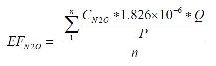
Equation 50-1a:
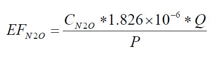
Where:
- EFN2O
- Average facility-specific N2O emissions factor without using N2O abatement technology (kg N2O generated/tonne adipic acid produced).
- CN2O
- average N2O concentration during the performance test or average hourly concentrations for continuous process monitors (ppm N2O).
- 1.826 × 10⁻⁶
- Conversion factor (kg/dSm3-ppm N2O).
- Q
- average volumetric flow rate of effluent gas per test run during the performance test or average hourly readings for continuous monitor (dSm³/hr).
- P
- average production rate during the performance test or the average hourly production rate for continuous monitors during the period (tonnes adipic acid produced per hour).
- n
- Number of test runs.
- If applicable, the person shall determine the destruction efficiency for each N2O abatement technology used at the facility according to paragraphs (d)(1), (d)(2), (d)(3) or (d)(4)of this section.
- Use the manufacturer’s specified destruction efficiency.
- Estimate the destruction efficiency through process knowledge. Examples of information that could constitute process knowledge include calculations based on material balances, process stoichiometry, or previous test results provided the results are still relevant to the current vent stream conditions. The person shall document how process knowledge was used to determine the destruction efficiency.
- Calculate the destruction efficiency by conducting an additional performance test on the emissions stream following the N2O abatement technology.
- Calculate the destruction efficiency by the use of continuous monitors on the controlled and uncontrolled emissions.
If applicable, the person shall determine the abatement factor for each N2O abatement technology used at the facility. The abatement factor is calculated for each adipic acid facility according to Equation 50-2 of this section.
Equation 50-2:
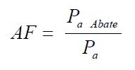
Where:
- AF
- Abatement factor of N2O abatement technology (fraction of production in the testing period that abatement technology is operating).
- Pa Abate
- adipic acid production in the testing period during which N2O abatement was used (tonne acid produced).
- Pa
- Total adipic acid production in the testing period (tonne acid produced).
- The person shall determine the annual amount of adipic acid produced and the annual adipic acid production during which N2O abatement is operating.
The person shall calculate annual adipic acid production process emissions of N2O by multiplying the emissions factor (determined using Equation 50-1 or 50-1a of this section) by the adipic acid production for each period and accounting for N2O abatement, according to Equation 50-3 of this section:
Equation 50-3:
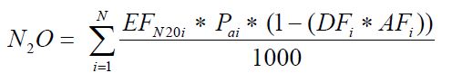
Where:
- N2O
- Annual N2O mass emissions from adipic acid production (tonnes).
- EFN2Oi
- Facility-specific N2O emissions factor for the period without abatement technology (kg N2O generated/tonne adipic acid produced).
- Pai
- Adipic acid produced in the period (tonnes).
- DFi
- Destruction efficiency of N2O abatement technology in the period (abatement device destruction efficiency, per cent of N2O removed from air stream).
- AFi
- Abatement factor of N2O abatement technology in the period (fraction of period that is production abatement technology is operating).
- 1000
- Conversion factor (kg/tonne).
- N
- Number of different periods in the year. For performance test, the period would be the time between each test (e.g., N is 1 year if performance test conducted annually). For continuous monitors, N would be the number of months in the year (or more), with Pai, EFN2Oi, DFi and AFi to be calculated for each month.
ON.54 Sampling, Analysis, and Measurement Requirements
- The person shall conduct a new performance test and calculate a new facility-specific emissions factor according to the frequency specified in paragraphs (a)(1) of this section, or use continuous monitors to calculate a facility-specific emissions factor and destruction efficiency according to paragraphs (a)(2) of this section.
- Performance Test
- Conduct the performance test annually or
- Conduct the performance test when the adipic acid production process is changed either by altering the ratio of cyclohexanone to cyclohexanol or by installing abatement equipment.
- Continuous Monitors
- Continuous process monitors shall be used to determine the uncontrolled emissions and the controlled N2O emissions to derive an N2O emission factor and abatement system destruction factor.
- The continuous process monitors shall be operated in accordance with quality assurance and quality control programs.
- Performance Test
- The person shall measure the N2O concentration during the performance test using one of the following methods:
- Any of the applicable analytical methods listed in the Technical Reference Document section of this Guideline (section 5),
- The most appropriate method published by a consensus-based standards organization, if such a method exists. If no appropriate method is published by a consensus-based standards organization, use industry standard methods, noting where such methods are used and what methods are used
- The person shall determine the production rate(s) during the performance test and the annual adipic acid production according to either of the following methods:
- Direct measurement (such as using flow meters or weigh scales).
- Existing plant procedures used for accounting purposes (such as sales records).
- The person shall conduct all required performance tests according to the methods in ON.54(b). For each test, the facility shall prepare an emissions factor determination report that shall include the following items.
- Analysis of samples, determination of emissions, and raw data.
- All information and data used to derive the emissions factor.
- The production rate(s) during the performance test and how each production rate was determined.
- The person shall determine the monthly adipic acid production quantity and the monthly adipic acid production during which N2O abatement technology is operating according to the methods in paragraphs (c)(1) or (c)(2) of this section.
- The person shall determine the annual adipic acid production quantity and the annual adipic production quantity during which N2O abatement technology is operating by summing the respective monthly adipic acid production quantities. The equipment used to measure the production quantity shall:
- be calibrated according to the manufacturer’s instructions; and
- be maintained to achieve an accuracy of plus or minus 5%.
ON.55 Procedures for Estimating Missing Data
Unavailable analytical Data
- Whenever analytical data relating to sampling is unavailable, the person shall, using the methods prescribed in ON.54, re-analyze the original sample, a backup sample or a replacement sample for the same measurement and sampling period.
Determination of quantity
- Whenever sampling and measurement data required by ON.54 for the calculation of emissions is missing the person shall ensure that the data is replaced using the following missing data procedures:
- When data determined on the basis of a performance test required by ON.54 is missing, conduct a new performance test;
- When the missing data is not data prescribed in a performance test and concerns carbon content, temperature, pressure or gas concentration, the person shall:,
Determine the sampling or measurement rate that was used using the following Equation 50-4:
Equation 50-4:
R = QSAct ⁄ QSRequired
Where:
- R
- Sampling or measurement rate that was used, expressed as a percentage
- QSAct
- Quantity of actual samples or measurements obtained by the person
- QSRequired
- Quantity of samples or measurements required under ON.54
- Replace the missing data as follows`
- If R ≥ 0.9: replace the missing data by the arithmetic mean of the sampling or measurement data from immediately before and after the missing data period. If no data is available from before the missing data period, the person shall use the first available data from after the missing data period;
- If 0.75 ≤ R < 0.9: replace the missing data by the highest data value sampled or analyzed during the reporting period for which the calculation is made;
- If R < 0.75: replace the missing data by the highest data value sampled or analyzed during the 3 preceding years;
- When the missing data concerns adipic acid production or gas flow rate, the replacement data shall be generated from best estimates based on all of the data relating to the processes.
- For all units subject to the requirements of ON.20 that monitor and report emissions using a CEMS, the missing data backfilling procedures in EPS 1/PG/7 shall be followed for CO2 concentration, stack gas flow rate, fuel flow rate, high heating value, and fuel carbon content.
ON.80 Ammonia Production
ON.81 Activity Definition
For the purposes of this standard quantification method:
- Ammonia production
- has the same meaning as in the Regulation.
- Person
- means a person that engages in ammonia production.
ON.82 Greenhouse Gas Reporting Requirements
A person shall set out the following information, calculated for the calendar year using standard quantification methods ON.80 – ON.85, in an emission report prepared for a calendar year in respect of ammonia production at a facility:
- CO2 process emissions from steam reforming of a hydrocarbon or the gasification of solid and liquid raw material following the requirements in this section (tonnes).
- Annual quantity of each type of feedstock consumed for ammonia manufacturing (expressed in Sm3 for liquid feedstock or kilolitres for liquid feedstock or tonnes for solid feedstock).
- If a CEMS is not used to measure emissions, report the following information:
- Whether carbon content for each feedstock is based on reports from the supplier or analysis of carbon content.
- If a facility uses gaseous feedstock, the annual weighted average carbon content of each type of gaseous feedstock (kg C per kg of feedstock).
- If a facility uses liquid feedstock, the annual weighted average carbon content of each type of liquid feedstock (kg C per kilolitre of feedstock).
- If a facility uses solid feedstock, the annual weighted average carbon content of each type of solid feedstock (kg C per kg of feedstock).
- Annual urea production (tonnes)
- Annual ammonia production (tonnes)
ON.83 Calculating GHG emissions
The person shall calculate and report the annual process CO2 emissions from each ammonia manufacturing process unit using the procedures in either paragraph (a) or (b) of this section.
- Calculate and report the process CO2 emissions by operating and maintaining CEMS according to Calculation Methodology 4 specified in ON.23 and all associated requirements for methodology 4 in ON.20.
- Calculate and report process CO2 emissions using the procedures in paragraphs (b)(1) through (b)(6) of this section for gaseous feedstock, liquid feedstock, or solid feedstock, as applicable.
Gaseous feedstock. The person shall calculate the CO2 process emissions from gaseous feedstock according to Equation 80-1 of this section:
Equation 80-1:
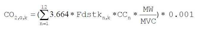
Where:
- CO2,G,k
- Annual CO2 emissions arising from feedstock consumption (tonnes).
- Fdstkn,k
- Volume of the gaseous' feedstock used in month n (Rm3 of feedstock) at reference temperature and pressure conditions as used by the facility. If a mass flow meter is used, measure the feedstock used in the month n as kg feedstock and replace the term “MW⁄MVC” with “1”.
- CCn
- Carbon content of the gaseous feedstock, for month n, (kg C per kg of feedstock), determined according to ON.84(c).
- MW
- Molecular weight of the gaseous feedstock (kg/kg-mole).
- MVC
- Molar volume conversion factor at the same reference conditions as the above Fdstkn,k (Rm3/kg-mole).
- 8.3145 × [273.16 + reference temperature in °C] ⁄ [reference pressure in kilopascal]
- 3.664
- Ratio of molecular weights, CO2 to carbon.
- 0.001
- Conversion factor from kg to tonnes.
- k
- Processing unit.
- n
- Number of month
Liquid feedstock. The person shall calculate, from each ammonia manufacturing unit, the CO2 process emissions from liquid feedstock according to Equation 80-2 of this section:
Equation 80-2:
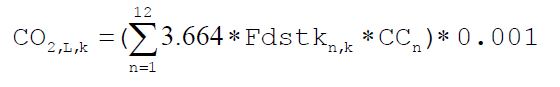
Where:
- CO2,L,k
- Annual CO2 emissions arising from feedstock consumption (tonnes).
- Fdstkn,k
- Volume of the liquid feedstock used in month n (kilolitres of feedstock). If a mass flow meter is used, measure the feedstock used in month n as kg of feedstock and measure the carbon content of feedstock in kg C per kg of feedstock.
- CCn
- Carbon content of the liquid feedstock, for month n as determined according to ON.84(c). (kg of C per kilolitre of feedstock when feedstock consumption is measured in kilolitres or kg of C per kg of feedstock when feedstock consumption is measured in kg.
- 3.664
- Ratio of molecular weights, CO2 to carbon.
- 0.001
- Conversion factor from kg to tonnes.
- k
- Processing unit.
- n
- Number of months
Solid feedstock. The person shall calculate, from each ammonia manufacturing unit, the CO2 process emissions from solid feedstock according to Equation 80-3 of this section:
Equation 80-3:
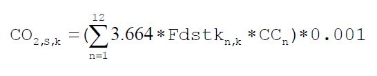
Where:
- CO2,S,k
- Annual CO2 emissions arising from feedstock consumption (tonnes).
- Fdstkn,k
- Mass of the solid feedstock used in month n (kg of feedstock).
- CCn
- Carbon content of the solid feedstock, for month n, (kg C per kg of feedstock), determined according to ON.84(c).
- 3.664
- Ratio of molecular weights, CO2 to carbon.
- 0.001
- Conversion factor from kg to tonnes.
- k
- Processing unit.
- n
- Number of months
The person shall calculate the annual process CO2 emissions from each ammonia processing unit k at the facility summing emissions, as applicable from Equations 80-1, 80-2, and 80-3 of this section using Equation 80-4.
Equation 80-4:
ECO2k = CO2,G,k + CO2,S,k + CO2,L,k
Where:
- ECO2k
- Annual CO2 emissions from each ammonia processing unit k (tonnes).
- k
- Processing unit.
The person shall determine the combined CO2 emissions from all ammonia processing units at the facility using Equation 80-5 of this section.
Equation 80-5:
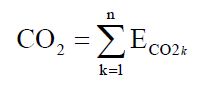
Where:
- CO2
- Annual combined CO2 emissions from all ammonia processing units (tonnes).
- ECO2k
- Annual CO2 emissions from each ammonia processing unit (tonnes).
- k
- Processing unit.
- n
- Total number of ammonia processing units.
- If GHG emissions from an ammonia manufacturing unit are vented through the same stack as any combustion unit or process equipment that reports CO2 emissions using a CEMS that complies with Calculation Methodology 4 in ON.23, then the calculation methodology in paragraph (b) of this section shall not be used to calculate process emissions. The person shall report under this section the combined stack emissions according to Calculation Methodology 4 in ON.23 and all associated requirements for Calculation Methodology 4 in ON.20.
ON.84 Sampling, Analysis, and Measurement Requirements
- The person shall continuously measure the quantity of gaseous or liquid feedstock consumed using a flow meter. The quantity of solid feedstock consumed can be obtained from company records and aggregated on a monthly basis.
- The person shall document the procedures used to ensure the accuracy of the estimates of feedstock consumption.
- The person shall determine monthly carbon contents and the average molecular weight of each feedstock consumed from reports from the supplier. As an alternative to using supplier information on carbon contents, the person can also collect a sample of each feedstock on a monthly basis and analyze the carbon content and molecular weight of the fuel using any of the following methods.
- Any of the applicable analytical methods listed in the Technical Reference Document section of this Guideline (section 5),
- The most appropriate method published by a consensus-based standards organization, if such a method exists. If no appropriate method is published by a consensus-based standards organization, use industry standard methods, noting where such methods are used and what methods are used.
- Calibrate all oil and gas flow meters (except for gas billing meters) and perform oil tank measurements according to the monitoring and QA/QC requirements specified in section ON.25(b)(3).
- If CO2 from ammonia production is used to produce urea at the same facility, the person shall determine the quantity of urea produced using methods or plant instruments used for accounting purposes (such as sales records). The person shall document the procedures used to ensure the accuracy of the estimates of urea produced.
- The person shall measure the ammonia produced. The equipment used to measure the production shall be:
- calibrated according to the manufacturer’s instructions and
- maintained an accuracy of plus or minus 5%.
ON.85 Procedures for Estimating Missing Data
Unavailable analytical Data
- Whenever analytical data relating to sampling is unavailable, the person shall, using the methods prescribed in ON.84, re-analyze the original sample, a backup sample or a replacement sample for the same measurement and sampling period.
Determination of quantity
- Whenever sampling and measurement data required by ON.84 for the calculation of emissions is missing the person shall ensure that the data is replaced using the following missing data procedures:
- When data determined on the basis of a performance test required by ON.84 is missing, conduct a new performance test;
- When the missing data concerns carbon content, temperature, pressure or gas concentration, the person shall:,
Determine the sampling or measurement rate using the following Equation 80-6:
Equation 80-6:
R = QSAct ⁄ QSRequiredWhere:
- R
- Sampling or measurement rate that was used, expressed as a percentage
- QSAct
- Quantity of actual samples or measurements obtained by the person
- QSRequired
- Quantity of samples or measurements required under ON.84
- Replace the missing data as follows,
- If R ≥ 0.9: replace the missing data by the arithmetic mean of the sampling or measurement data from immediately before and after the missing data period. If no data is available from before the missing data period, the person shall use the first available data from after the missing data period;
- If 0.75 ≤ R < 0.9: replace the missing data by the highest data value sampled or analyzed during the reporting period for which the calculation is made;
- If R < 0.75: replace the missing data by the highest data value sampled or analyzed during the 3 preceding years;
- When the missing data concerns raw material quantity, ammonia production or waste gas consumption, the replacement data shall be generated from best estimates based on all of the data relating to the processes.
- For all units subject to the requirements of ON.20 that monitor and report emissions using a CEMS, the missing data backfilling procedures in EPS 1/PG/7 shall be followed for CO2 concentration, stack gas flow rate, fuel flow rate, high heating value, and fuel carbon content.
ON.180 Carbonate Use
ON.181 Activity Definition
For the purposes of this standard quantification method:
- Carbonate use
- has the same meaning as in the Regulation.
- Person
- means a person that engages in carbonate use.
ON.182 Greenhouse Gas Reporting Requirements
A person shall set out the following information, calculated for the calendar year using standard quantification methods ON.180 – ON.185, in an emission report prepared for a calendar year in respect of carbonate use at a facility:
- Annual CO2 emissions from miscellaneous carbonate use (tonnes).
- If the person followed the calculation methodology contained in ON.183(a), the person shall report the following information:
- Annual carbonate consumption by carbonate type (tonnes).
- Annual calcination fractions used in calculations.
- If the person followed the calculation methodology contained in ON.183(b), the person shall report the following information:
- Annual carbonate input by carbonate type (tonnes).
- Annual carbonate output by carbonate type (tonnes).
ON.183 Calculating GHG emissions
The person shall determine CO2 process emissions from carbonate use in accordance with the procedures specified in either paragraph (a) or (b) of this section.
Calculate the process emissions of CO2 using calcination fractions with Equation 180-1 of this section.
Equation 180-1:
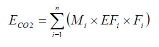
Where:
- ECO2
- Annual CO2 mass emissions from consumption of carbonates (tonnes).
- Mi
- Annual mass of carbonate type i consumed (tonnes).
- EFi
- Emission factor for the carbonate type i, as specified in Table 180-1 to this section, tonnes CO2/tonne carbonate consumed.
- Fi
- Fraction calcination achieved for each particular carbonate type i (weight fraction). As an alternative to measuring the calcination fraction, a value of 1.0 can be used.
- n
- Number of carbonate types.
Calculate the process emissions of CO2 using actual mass of output carbonates with Equation 180-2 of this section.
Equation 180-2:
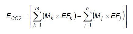
Where:
- ECO2
- Annual CO2 mass emissions from consumption of carbonates (tonnes).
- Mk
- Annual mass of input carbonate type k (tonnes).
- EFk
- Emission factor for the input carbonate type k, as specified in Table 180-1 of this section (tonnes CO2/tonne carbonate).
- Mj
- Annual mass of output carbonate type j (tonnes).
- EFj
- Emission factor for the output carbonate type j, as specified in Table 180-1 of this section (tonnes CO2/tonne carbonate).
- m
- Number of input carbonate types.
- n
- Number of output carbonate types.
ON.184 Sampling, Analysis, and Measurement Requirements
- The annual mass of carbonate consumed (for Equation 180-1 of this section) or carbonate inputs (for Equation 180-2 of this section) shall be determined annually from monthly measurements using the same plant instruments used for accounting purposes including purchase records or direct measurement, such as weigh hoppers or weigh belt feeders.
- The annual mass of carbonate outputs (for Equation 180-2 of this section) shall be determined annually from monthly measurements using the same plant instruments used for accounting purposes including purchase records or direct measurement, such as weigh hoppers or belt weigh feeders.
- If the person followed the procedures of ON.183(a), rather than assuming a calcination fraction of 1.0, the person may determine, on an annual basis, the calcination fraction for each carbonate consumed using one of the following:
- Any of the applicable analytical methods listed in the Technical Reference Document section of this Guideline (section 5);
- The most appropriate method published by a consensus-based standards organization, if such a method exists. If no appropriate method is published by a consensus-based standards organization, use industry standard methods, noting where such methods are used and what methods are used.
ON.185 Procedures for Estimating Missing Data
Unavailable analytical Data
- Whenever analytical data relating to sampling is unavailable, the person shall, using the methods prescribed in ON.184, re-analyze the original sample, a backup sample or a replacement sample for the same measurement and sampling period.
Determination of quantity
- Whenever sampling and measurement data required by ON.184 for the calculation of emissions is missing the person shall ensure that the data is replaced using the following missing data procedures:
- When the missing data concerns carbon content, temperature, pressure or gas concentration, the person shall:
Determine the sampling or measurement rate using the following Equation 180-3:
Equation 180-3:
R = QS Act ⁄ QS RequiredWhere:
- When the missing data concerns carbon content, temperature, pressure or gas concentration, the person shall:
- R
- Sampling or measurement rate that was used, expressed as a percentage
- QSAct
- Quantity of actual samples or measurements obtained by the person
- QSRequired
- Quantity of samples or measurements required under ON.184
- Replace the missing data as follows,
- If R ≥ 0.9: replace the missing data by the arithmetic mean of the sampling or measurement data from immediately before and after the missing data period. If no data is available from before the missing data period, the person shall use the first available data from after the missing data period;
- If 0.75 ≤ R < 0.9: replace the missing data by the highest data value sampled or analyzed during the reporting period for which the calculation is made;
- If R < 0.75: replace the missing data by the highest data value sampled or analyzed during the 3 preceding years;
- When the missing data concerns raw material consumption or carbonate consumption, the replacement data shall be generated from best estimates based on all of the data relating to the processes.
- For all units subject to the requirements of ON.20 that monitor and report emissions using a CEMS, the missing data backfilling procedures in EPS 1/PG/7 shall be followed for CO2 concentration, stack gas flow rate, fuel flow rate, high heating value, and fuel carbon content.
| Mineral Name - Carbonate | CO2 Emission Factor (tonnes CO2/tonne carbonate) |
|---|---|
| Limestone - CaCO3 | 0.43971 |
| Magnesite - MgCO3 | 0.52197 |
| Dolomite - CaMg(CO3)2 | 0.47732 |
| Siderite - FeCO3 | 0.37987 |
| Ankerite - Ca(Fe,Mg,Mn)(CO3)2 | 0.47572 |
| Rhodochrosite - MnCO3 | 0.38286 |
| Sodium Carbonate/Soda Ash Na2CO3 | 0.41492 |
| Others | Facility specific factor to be determined through analysis or supplier information or using stoichiometric ratio |
ON.90 Cement Production
ON.91 Activity Definition
For the purposes of this standard quantification method:
- cement production
- has the same meaning as in the Regulation.
- Person
- means a person that engages in cement production.
ON.92 Greenhouse Gas Reporting Requirements
A person shall set out the following information, calculated for the calendar year using standard quantification methods ON.90 – ON.95, in an emission report prepared for a calendar year in respect of cement production at a facility:
- Annual CO2 process emissions (excluding emissions from fuel combustion) in tonnes.
- Report the following information if the process CO2 emissions are calculated according to the procedures specified in ON.93(b)(1):
- Monthly plant specific clinker emission factors (tonnes CO2/tonnes clinker).
- Monthly quantities of clinker produced (tonnes).
- Monthly total calcium content of clinker, expressed as calcium oxide (CaO) (weight fraction, tonne CaO/tonne clinker).
- Monthly total magnesium content of clinker, expressed as magnesium oxide (MgO) (weight fraction, tonne MgO/tonne clinker).
- Monthly non-calcined calcium oxide content of clinker, expressed as CaO (weight fraction, tonne CaO/tonne clinker).
- Monthly non-calcined magnesium oxide content of clinker, expressed as MgO (weight fraction, tonne MgO/tonne clinker).
- Monthly quantity of non-carbonate raw materials entering the kiln (tonnes).
- Quarterly cement kiln dust (CKD) emission factor (tonne CO2/tonne CKD not recycled back to kilns).
- Quarterly quantity of CKD not recycled back to kilns (tonnes).
- Monthly plant specific clinker emission factors (tonnes CO2/tonnes clinker).
- Annual CO2 process emissions from organic carbon oxidation (tonnes) and the following information if the process CO2 emissions are calculated according to the procedures specified in ON.93(b)(2):
- Amount of raw material consumed in the report year (tonnes).
- Annual organic carbon content of raw material (weight. fraction).
- Annual CO2, CH4, and N2O emissions from fuel combustion in all kilns combined, following the calculation methodology and reporting requirements specified in ON.93(c) (tonnes).
- Annual clinker production, and quantity of gypsum and limestone added as mineral additives to the clinker at the facility (tonnes)
ON.93 Calculation of GHG Emissions from Kilns
- Determine CO2 emissions as specified under either paragraph (a)(1) or (a)(2) of this section.
- Calculate the total process and combustion CO2 emissions from all the kilns using a continuous emissions monitoring system (CEMS) as specified in Calculation Methodology 4 in ON.23 and combustion CO2 emissions from all the kilns using the calculation methodologies specified in paragraph (c) of this section.
- Calculate the sum of CO2 process emissions from kilns and CO2 fuel combustion emissions from kilns using the calculation methodologies specified in paragraphs (b) and (c) of this section.
Process CO2 Emissions Calculation Methodology. Calculate total CO2 process emissions as the sum of emissions from calcination, using the method specified in paragraph (b)(1) of this section; and from organic carbon oxidation, using the method specified in paragraph (b)(2) of this section (Equation 90-1).
Equation 90-1:
ECO2-P = ECO2-C + ECO2-F
Where:
- ECO2-P
- Annual process CO2 emissions, tonnes/year.
- ECO2-C
- Annual process CO2 emissions from calcination, tonnes/year.
- ECO2-F
- Annual process CO2 emissions from feed oxidation, tonnes/year.
Calcination Emissions. Calculate CO2 process emissions from calcination using Equation 90-2 and a plant-specific clinker emission factor and a plant-specific cement kiln dust (CKD) emission factor as specified in this section.
Equation 90-2:
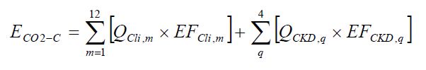
Where:
- ECO2-C
- Annual process CO2 emissions from calcination, tonnes.
- QCli,m
- Quantity of clinker produced in month m, tonnes.
- EFCli,m
- CO2 emission factor for clinker in month m, computed as specified in paragraph (b)(1)(i) of this section, tonnes CO2/tonne clinker.
- QCKD,q
- Quantity CKD not recycled to kilns in quarter q, tonnes.
- EFCKD,q
- CO2 emission factor for CKD not recycled to the kilns, computed as specified in paragraph (b)(1)(ii) of this section, tonnes CO2/tonne CKD.
Clinker Emission Factor. Calculate a plant-specific clinker emission factor (EFCli) for each month based on monthly measurements of the weight fractions of calcium (as CaO) and magnesium (as MgO) content in the clinker and in the non-carbonate raw materials entering the kiln, using Equation 90-3,.
Equation 90-3:
EFCli = (CaOCli − CaOf) × 0.785 + (MgOCli − MgOf) × 1.092
Where:
- EFCli
- Monthly CO2 emission factor for clinker, tonne CO2/tonne clinker
- CaOCli
- Monthly total calcium content of clinker expressed as calcium oxide, tonne CaO/tonne clinker.
- CaOf
- Monthly non-calcined calcium oxide content of clinker, tonne CaO/tonne clinker.
- MgOCli
- Monthly total magnesium content of clinker expressed as magnesium oxide, tonne MgO/tonne clinker.
- MgOf
- Monthly non-calcined magnesium oxide content of clinker, tonne MgO/tonne clinker.
- 0.785
- Ratio of molecular weights of CO2 to CaO
- 1.092
- Ratio of molecular weights of CO2 to MgO
CKD Emission Factor. If CKD is generated and not recycled back to the kilns, then calculate a plant-specific CKD emission factor based on quarterly sampling. The CKD emission factor shall be calculated using Equation 90-4.
Equation 90-4:
EFCKD = (CaOCKD − CaOf) × 0.785 + (MgOCKD − MgOf) × 1.092
Where:
- EFCKD
- Quarterly CO2 emission factor for CKD not recycled to the kilns, tonne CO2/tonne CKD.
- CaOCKD
- Quarterly total calcium oxide content of CKD not recycled to the kilns, tonne CaO/tonne CKD.
- CaOf
- Quarterly non-calcined calcium oxide content of CKD not recycled to the kilns, tonne CaO/tonne CKD.
- MgOCKD
- Quarterly total magnesium oxide content of CKD not recycled to the kilns, tonne MgO/tonne CKD.
- MgOf
- Quarterly non-calcined magnesium oxide content of CKD not recycled to the kilns, tonne MgO/tonne CKD.
- 0.785
- Ratio of molecular weights of CO2 to CaO
- 1.092
- Ratio of molecular weights of CO2 to MgO
Organic Carbon Oxidation Emissions. Calculate CO2 process emissions from the total organic content in raw materials by using Equation 90-5.
Equation 90-5:
ECO2-RM = TOCRM × RM × 3.664
Where:
- ECO2-RM
- Annual process CO2 emissions from raw material oxidation, tonnes.
- TOCRM
- Total organic carbon content in raw material (weight. fraction), measured using the method in ON.94(b) or using a default of 0.002 (0.2%).
- RM
- Amount of raw material consumed (tonnes/year).
- 3.664
- Ratio of molecular weights of carbon dioxide to carbon.
Fuel Combustion Emissions in Kilns. Calculate CO2, CH4, and N2O emissions from stationary fuel combustion in accordance with the calculation methodologies specified in ON.20. Cement plants that combust pure biomass-derived fuels and combust fossil fuels only during periods of start-up, shut-down, or malfunction may report CO2 emissions from fossil fuels using Calculation Methodology 1in ON.23. “Pure” means that the biomass-derived fuels account for at least 97 per cent of the total amount of carbon in the fuels burned.
Cement plants that report CO2 emissions from kilns using continuous emissions monitoring system under ON.93(a)(1) may report:
- Fuel combustion CO2 emissions in kilns by subtracting the total emissions calculated using ON.93(a)(1) from the process CO2 emissions calculated using ON.93(b); or
- Fuel combustion CO2 emissions in kilns using Calculation Methodology 1 in ON.23 and fuel sampling based on the same plant techniques used for accounting purposes.
ON.94 Sampling, Analysis, and Measurement Requirements
- Determine the monthly plant-specific weight fractions of total calcium (as CaO) and total magnesium (as MgO) in clinker using one of the following:
- Any of the applicable analytical methods listed in the Technical Reference Document section of this Guideline (section 5);
- The most appropriate method published by a consensus-based standards organization, if such a method exists. If no appropriate method is published by a consensus-based standards organization, use industry standard methods, noting where such methods are used and what methods are used.
Determine quarterly the plant-specific weight fractions of total calcium (as CaO) and total magnesium (as MgO) in CKD using one of the following:
- Any of the analytical methods listed in the Technical Reference Document section of this Guideline (section 5);
- The most appropriate method published by a consensus-based standards organization, if such a method exists. If no appropriate method is published by a consensus-based standards organization, use industry standard methods, noting where such methods are used and what methods are used.
The monitoring shall be conducted either daily from CKD samples drawn from the exit of the kiln or quarterly from CKD samples drawn from bulk storage.
- Determine monthly the plant-specific weight fractions of calcium oxide (CaO) and magnesium oxide (MgO) that enters the kiln as a non-carbonate species to clinker by chemical analysis of feed material using documented analytical method or the appropriate industrial standard practice, or use a value of 0.0.
- Determine quarterly the plant-specific weight fractions of calcium oxide (CaO) and magnesium oxide (MgO) that enters the kiln as a non-carbonate species to CKD by chemical analysis of feed material using documented analytical method or the appropriate industrial standard practice, or use a value of 0.0.
- Determine monthly the plant-specific weight fractions of calcium oxide (CaO) and magnesium oxide (MgO) that remains in clinker by chemical analysis of feed material using documented analytical method or the appropriate industrial standard practice, or use a value of 0.0.
- Determine quarterly the plant-specific weight fractions of calcium oxide (CaO) and magnesium oxide (MgO) that remains in CKD by chemical analysis of feed material using documented analytical method or the appropriate industrial standard practice, or use a value of 0.0.
- Determine annually the total organic carbon contents of raw materials using ASTM C114, an equivalent industry method for total organic carbon determination in raw mineral material, or use a default value of 0.002. The analysis shall be conducted on sample material drawn from bulk raw material storage for each category of raw material.
- The quantity of clinker produced shall be determined monthly by either:
- Direct weight measurement using the same plant techniques used for accounting purposes, such as reconciling weigh hoppers or belt weigh feeders measurements against inventory measurements, or
- Direct measurement of raw kiln feed and application of a kiln-specific feed-to-clinker factor. Facilities that opt to use a feed to clinker factor shall verify the accuracy of this factor on a monthly basis.
- The quantity of CKD not recycled back to the kiln shall be determined quarterly by either using the same plant techniques used for accounting purposes, such as direct weight measurement using weigh hoppers or belt weigh feeders, and/or material balances.
- The quantity of raw materials consumed (i.e. limestone, sand, shale, iron oxide, alumina, and non-carbonate raw material) shall be determined monthly by direct weight measurement using the same plant instruments used for accounting purposes, such as weigh hoppers or belt weigh feeders.
- The quantity of limestone and gypsum blended with the clinker shall be determined monthly by direct weight measurement using the same plant instruments used for accounting purposes.
- Equipment used to measure the clinker, limestone and gypsum shall be:
- calibrated according to the manufacturer’s instructions and
- maintained to achieve an accuracy of plus or minus 5%.
ON.95 Procedures for Estimating Missing Data
Unavailable analytical Data
- Whenever analytical data relating to sampling is unavailable, the person shall using the methods prescribed in ON.94, re-analyze the original sample, a backup sample or a replacement sample for the same measurement and sampling period.
Determination of quantity
- Whenever sampling and measurement data required by ON.94 for the calculation of emissions is missing the person shall ensure that the data is replaced using the following missing data procedures:
- When the missing data concerns carbon content, temperature, pressure or gas concentration, the person shall:
Determine the sampling or measurement rate using the following Equation 90-4:
Equation 90-4:
R = QSAct⁄QSRequired
- When the missing data concerns carbon content, temperature, pressure or gas concentration, the person shall:
- R
- Sampling or measurement rate that was used, expressed as a percentage
- QSAct
- Quantity of actual samples or measurements obtained by the person
- QSRequired
- Quantity of samples or measurements required under ON.94
- Replace the missing data as follows,
- If R ≥ 0.9: replace the missing data by the arithmetic mean of the sampling or measurement data from immediately before and after the missing data period. If no data is available from before the missing data period, the person shall use the first available data from after the missing data period;
- If 0.75 ≤ R < 0.9: replace the missing data by the highest data value sampled or analyzed during the reporting period for which the calculation is made;
- If R < 0.75: replace the missing data by the highest data value sampled or analyzed during the 3 preceding years;
- When the missing data concerns clinker production, the person shall use the first data estimated after the period for which the data is missing or use the maximum daily production capacity and multiply it by the number of days in the month;
- When the missing data concerns raw material consumption, the person shall use the first data estimated after the period for which the data is missing or use the maximum rate of raw materials entering the kiln and multiply by the number of days in the month;
- When the missing data concerns the quantity of dust, the quantity of gypsum or the quantity of limestone, the replacement data shall be generated from best estimates based on all of the data relating to the processes.
- For all units subject to the requirements of ON.20 that monitor and report emissions using a CEMS, the missing data backfilling procedures in EPS 1/PG/7 shall be followed for CO2 concentration, stack gas flow rate, fuel flow rate, high heating value, and fuel carbon content.
ON.100 Coal Storage
ON.101 Activity Definition
For the purposes of this standard quantification method:
- Coal storage
- has the same meaning as in the Regulation.
- Person
- means a person that engages in coal storage.
ON.102 Greenhouse Gas Reporting Requirements
A person shall set out the following information, calculated for the calendar year using standard quantification methods ON.100 – ON.105, in an emission report prepared for a calendar year in respect of coal storage at a facility:
- Annual greenhouse gas emissions in tonnes, reported as follows:
- Total CH4 emissions.
- Annual coal purchases (tons for US; tonnes for Canada).
- Source of coal purchases:
- Coal basin.
- State/province.
- Coal mine type (surface or underground).
ON.103 Calculation of CH4 Emissions
Calculate fugitive CH4 emissions from coal storage piles as specified under paragraph (a), (b), or (c) of this section.
- For coal purchased from US sources, calculate fugitive CH4 emissions using Equation 100-1 and Table 100-1.
- For coal purchased from Canadian sources, calculate fugitive CH4 emissions using Equation 100-1 and Table 100-2.
For coal purchased from non-US and non-Canadian sources, the person shall use either ON.103(a) or ON.103(b), whichever is the most applicable.
Equation 100-1:
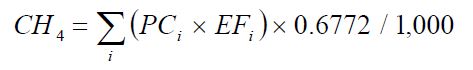
Where:
- CH4
- Fugitive emissions from coal storage piles for each coal category i, (tonnes CH4 per year);
- PCi
- Purchased coal for each coal category i (tonnes per year);
- EFi
- Default CH4 emission factor for each coal category i specified by location and mine type that coal originated from, provided in Table 100-2 (m3 CH4 per tonne of coal);
- 0.6772
- Methane conversion factor to convert m3 to kg;
- 1,000
- Factor to convert kg to tonnes.
ON.104 Sampling, Analysis, and Measurement Requirements
Coal Purchase Monitoring Requirements
Facilities may determine the quantity of coal purchased either using records provided by the coal supplier(s) or monitoring coal purchase quantities using the same plant instruments used for accounting purposes, such as weigh hoppers or belt weigh feeders.
ON.105 Procedures for Estimating Missing Data
When the missing data is relating to the total quantity of coal purchased, the replacement data shall be generated from best estimates based on all of the data relating to the processes.
| Coal Origin: Coal Basin | Coal Origin: States | Coal Mine Type: Surface Post-Mining Factors | Coal Mine Type: Underground Post-Mining Factors |
|---|---|---|---|
| Northern Appalachia | Maryland, Ohio, Pennsylvania, West Virginia North | 0.6025 | 1.4048 |
| Central Appalachia (WV) | Tennessee, West Virginia South | 0.2529 | 1.3892 |
| Central Appalachia (VA) | Virginia | 0.2529 | 4.0490 |
| Central Appalachia (E KY) | East Kentucky | 0.2529 | 0.6244 |
| Warrior | Alabama, Mississippi | 0.3122 | 2.7066 |
| Illinois | Illinois, Indiana, Kentucky West | 0.3465 | 0.6525 |
| Rockies (Piceance Basin) | Arizona, California, Colorado, New Mexico, Utah | 0.3372 | 1.9917 |
| Rockies (Uinta Basin) | Arizona, California, Colorado, New Mexico, Utah | 0.1623 | 1.0083 |
| Rockies (San Juan Basin) | Arizona, California, Colorado, New Mexico, Utah | 0.0749 | 1.0645 |
| Rockies (Green River Basin) | Arizona, California, Colorado, New Mexico, Utah | 0.3372 | 2.5068 |
| Rockies (Raton Basin) | Arizona, California, Colorado, New Mexico, Utah | 0.3372 | 1.2987 |
| N. Great Plains | Montana, North Dakota, Wyoming | 0.0562 | 0.1592 |
| West Interior (Forest City, Cherokee Basins) | Arkansas, Iowa, Kansas, Louisiana, Missouri, Oklahoma, Texas | 0.3465 | 0.6525 |
| West Interior (Arkoma Basin) | Arkansas, Iowa, Kansas, Louisiana, Missouri, Oklahoma, Texas | 0.7555 | 3.3591 |
| West Interior (Gulf Coast Basin) | Arkansas, Iowa, Kansas, Louisiana, Missouri, Oklahoma, Texas | 0.3372 | 1.2987 |
| Northwest (AK) | Alaska | 0.0562 | 1.6233 |
| Northwest (WA) | Washington | 0.0562 | 0.5900 |
Source: Inventory of US Greenhouse Gas Emissions and Sinks:1990 – 2005.
April 15, 2007, US Environmental Protection Agency. Annex 3, Methodological Descriptions for Additional Source or Sink Categories, Section 3.3, Table A-115, Coal Surface and Post-Mining CH4 Emission Factors (ft3 per Short Ton; converted to m3 per tonne). (Only Post-Mining EFs used from Table). State assignments shown from Table 113 of Annex 3.
| Coal Origin: Province | Coal Origin: Coalfield | Coal Mine Type: Surface Post-Mining Factors | Coal Mine Type: Underground Post-Mining Factors |
|---|---|---|---|
| British Columbia | Comox | 0.500 | n/a |
| British Columbia | Crowness | 0.169 | n/a |
| British Columbia | Elk Valley | 0.900 | n/a |
| British Columbia | Peace River | 0.361 | n/a |
| British Columbia | Province Average | 0.521 | n/a |
| Alberta | Battle River | 0.067 | n/a |
| Alberta | Cadomin-Luscar | 0.709 | n/a |
| Alberta | Coalspur | 0.314 | n/a |
| Alberta | Obed Mountain | 0.238 | n/a |
| Alberta | Sheerness | 0.048 | n/a |
| Alberta | Smokey River | 0.125 | 0.067 |
| Alberta | Wabamun | 0.176 | n/a |
| Alberta | Province Average | 0.263 | 0.067 |
| Saskatchewan | Estavan | 0.055 | n/a |
| Saskatchewan | Willow Bunch | 0.053 | n/a |
| Saskatchewan | Province Average | 0.054 | n/a |
| New Brunswick | Province Average | 0.060 | n/a |
| Nova Scotia | Province Average | n/a | 2.923 |
Source: Management of Methane Emissions from Coal Mines: Environmental, Engineering, Economic and Institutional Implications of Options. Prepared by Brian G. King, Neill and Gunter (Nova Scotia) Limited, Darmouth, Nova Scotia for Environment Canada. Contract Number K2031-3-7062. March 1994. This document is cited by Environment Canada in the NIR 1990-2007 (Final Submission, April 2009), but post-mining emission factors are not provided, so they were developed for WCI purposes by Province. Surface emission factors were derived from Table 3.1 (Coal production statistics [Column A] and post-mining emissions [Column F]). Underground emission factors were derived from Table 3.2 (Coal production statistics and post-mining emissions).
ON.260 Copper and Nickel Production
ON.261 Activity Definition
For the purposes of this standard quantification method:
- Copper and nickel production
- has the same meaning as in the Regulation.
- Person
- means a person that engages in copper and nickel production.
ON.262 Greenhouse Gas Reporting Requirements
A person shall set out the following information, calculated for the calendar year using standard quantification methods ON.260 – ON.265, in an emission report prepared for a calendar year in respect of copper and nickel production at a facility:
- Annual emissions of CO2 at the facility level (tonnes).
- Annual quantities of each carbonate flux reagent used (tonnes).
- Fractional purity of each carbonate flux reagent used (tonnes carbonate/tonnes reagent).
- Annual quantities of other reducing agents used (tonnes).
- Carbon content of other reducing agent used or material used for slag cleaning (tonnes C/tonne reducing agent or material for slag cleaning).
- Annual quantity of ore processed (tonnes).
- Carbon content of ore processed (tonnes C/tonne ore).
ON.263 Calculation of CO2 Emissions
Calculate total CO2 emissions as specified under paragraph (a) through (d) of this section.
Calculate CO2 emissions from carbonate flux reagents using Equation 260-1.
Equation 260-1:
Ecf = Qls × fls × (44 ⁄ 100) + Qd × fd × (88 ⁄ 184)Where:
- Ecf
- Annual CO2 emissions from carbonate flux reagents (tonnes);
- Qls
- Annual quantity of limestone consumed (tonnes);
- fls
- Fractional purity of limestone (tonnes CaCO3/tonnes of material);
- 44/100
- Stoichiometric conversion factor from CaCO3 to CO2;
- Qd
- Annual quantity of dolomite consumed (tonnes);
- fd
- Fractional purity of dolomite (tonnes CaCO3 · MgCO3/tonnes of material);
- 88 ⁄ 184
- Stoichiometric conversion factor from CaCO3 · MgCO3 to CO2.
Calculate CO2 emissions from other reducing agents or material used in slag cleaning using Equation 260-2.
Equation 260-2:
Era = Qa × Ca × 3.664Where:
- Era
- Annual CO2 emissions from other reducing agents or material used for slag cleaning (tonnes);
- Qa
- Annual quantity of other reducing agents or material used for slag cleaning (tonnes);
- Ca
- Carbon content of other reducing agents or material used for slag cleaning (tonnes C/tonne of reducing agent or material used for slag cleaning);
- 3.664
- ratio of molecular weights, carbon dioxide to carbon.
Calculate CO2 emissions from release of carbon from metal ores (including releases from solvent extraction) using Equation 260-3.
Equation 260-3:
Eore = Qore × Core × 3.664Where:
- Eore
- Annual process CO2 emissions from metal ore, tonnes
- Qore
- Annual quantity of nickel or copper metal ore consumed (tonnes);
- Core
- Carbon content of nickel or copper metal ore (tonnes C/tonne of nickel or copper ore);
- 3.664
- ratio of molecular weights, carbon dioxide to carbon.
Calculate CO2 emissions from carbon electrode consumption in electric arc furnaces (EAFs) using Equation 260-4.
Equation 260-4:
Ece = Qce × Cce × 3.664Where:
- Ece
- Annual CO2 emissions from carbon electrode consumption in EAFs (tonnes);
- Qce
- Quantity of carbon electrodes consumed (tonnes);
- Cce
- Carbon content of carbon electrodes (tonnes C/tonne carbon electrodes);
- 3.664
- ratio of molecular weights, carbon dioxide to carbon.
ON.264 Sampling, Analysis, and Measurement Requirements
The annual mass of each solid carbon-containing input material consumed shall be determined using facility instruments, procedures, or records used for accounting purposes, including either direct measurement of the quantity of the material consumed or by calculations using process operating information.
The average carbon content of each material consumed shall be determined as specified under paragraph (a) or (b) of this section.
- Obtain carbon content by collecting and analyzing at least three representative samples of the material each year using one of the following:
- Any of the applicable analytical methods listed in the Technical Reference Document section of this Guideline (section 5);
- The most appropriate method published by a consensus-based standards organization, if such a method exists. If no appropriate method is published by a consensus-based standards organization, use industry standard methods, noting where such methods are used and what methods are used.
- Obtain carbon content of the materials, including carbon electrodes, from the vendor or supplier.
ON.265 Procedures for Estimating Missing Data
Unavailable analytical Data
- Whenever analytical data relating to sampling is unavailable, the person shall, using the methods prescribed in ON.264, re-analyze the original sample, a backup sample or a replacement sample for the same measurement and sampling period.
Determination of quantity
- Whenever sampling and measurement data required by ON.264 for the calculation of emissions is missing the person shall ensure that the data is replaced using the following missing data procedures:
- When the missing data concerns carbon content, temperature, pressure or gas concentration, the person shall:
Determine the sampling or measurement rate using the following Equation 260-5:
Equation 260-5:
R = QSAct ⁄ QSRequired
Where:
- When the missing data concerns carbon content, temperature, pressure or gas concentration, the person shall:
- R
- Sampling or measurement rate that was used, expressed as a percentage
- QSAct
- Quantity of actual samples or measurements obtained by the person
- QSRequired
- Quantity of samples or measurements required under ON.264
- Replace the missing data as follows,
- If R ≥ 0.9: replace the missing data by the arithmetic mean of the sampling or measurement data from immediately before and after the missing data period. If no data is available from before the missing data period, the person shall use the first available data from after the missing data period;
- If 0.75 ≤ R < 0.9: replace the missing data by the highest data value sampled or analyzed during the reporting period for which the calculation is made;
- If R < 0.75: replace the missing data by the highest data value sampled or analyzed during the 3 preceding years;
- When the missing data concerns raw material consumption, carbonate consumption, reducing agent consumption, carbon electrode consumption, recycled material consumption or copper production, the replacement data shall be generated from best estimates based on all of the data relating to the processes.
- For all units subject to the requirements of ON.20 that monitor and report emissions using a CEMS, the missing data backfilling procedures in EPS 1/PG/7 shall be followed for CO2 concentration, stack gas flow rate, fuel flow rate, high heating value, and fuel carbon content.
ON.40 Electricity Generation
ON.41 Activity Definition
For the purposes of this standard quantification method:
- Electricity generation
- has the same meaning as in the Regulation.
- Person
- means a person that engages in electricity generation.
ON.42 Greenhouse Gas Reporting Requirements
A person shall set out the following information, calculated for the calendar year using standard quantification methods ON.40 – ON.45, in an emission report prepared for a calendar year in respect of electricity generation at a facility:
- Annual greenhouse gas emissions in tonnes, reported as follows:
- Total CO2 emissions for fossil fuels, reported by fuel type.
- Total CO2 emissions for all biomass fuels combined.
- Total CH4 emissions for all fuels combined.
- Total N2O emissions for all fuels combined.
- Annual fuel consumption:
- For gases, report in units of standard cubic meters.
- For liquids, report in units of kilolitres.
- For non-biomass solids, report in units of tonnes.
- For biomass-derived solid fuels, report in units of bone dry tonnes.
- Annual weighted average carbon content of each fuel, if used to compute CO2 emissions as specified in ON.43.
- Annual weighted average high heating value of each fuel, if used to compute CO2 emissions as specified ON.43.
- The nameplate generating capacity in megawatts (MW) and net power generated in the calendar year in megawatt hours (MWh).
- For each cogeneration unit,
- indicate whether topping or bottoming cycle,
- total thermal output including any output used for electricity generation, in MJ;
- useful thermal output excluding any energy used for electricity generation, in MJ,
- Where useful thermal output is acquired from another facility for the generation of electricity, report the provider and amount of acquired steam or heat in MJ.
- Where supplemental firing has been applied to support electricity generation, report this purpose and fuel consumption by fuel type using the units in ON.42(b).
- Process CO2 emissions from acid gas scrubbers and acid gas reagent.
- Fugitive emissions of each of the HFCs in Schedule 1 of the Regulation from cooling units that support power generation.
- Fugitive CO2 emissions from geothermal facilities.
- Fugitive CH4 emissions from coal storage at coal-fired electricity generating facilities shall be reported as specified in section ON.100.
- An attestation signed by the person or, where the person is not a natural person, an individual that is authorized to sign on behalf of the person confirming the total quantity of petroleum products received at the facility in the year from each supplier that supplied petroleum to the facility during the year.
ON.43 Calculation of Greenhouse Gas Emissions
- Calculation of CO2 Emissions. The person shall use CEMS to measure CO2 emissions if required to operate a CO2 CEMS with flow monitors by any other federal or provincial regulation. A person not required to operate a CEMS by another regulation may use either CEMS or the calculation methodologies specified in paragraphs (a)(1) through (a)(7). The person using CEMS to determine CO2 emissions shall comply with the provisions in Calculation Methodology 4 of ON.23.
- Natural Gas, and fuels in Table 20-1a. For electricity generating units combusting natural gas or the fuels listed in Table 20-1a, use methods in accordance with ON.23.
- Coal or Petroleum Coke. For electricity generating units combusting coal or petroleum coke, use the measured carbon content of the fuel and Calculation Methodology 3 in section ON.23.
- Middle Distillates, Gasoline, Residual Oil, or Liquid Petroleum Gases that are not listed in Table 20-1a. For electricity generating units combusting middle distillates, gasoline, use Calculation Methodology 2 or 3 in accordance with ON.23.
- Refinery Fuel Gas, Flexigas, or Associated Gas. For electricity generating units combusting refinery fuel gas, flexigas, or associated gas, use the methods specified in ON.30.
- Landfill Gas, Biogas, or Biomass. For electricity generating units combusting landfill gas, biogas, or biomass, use methods in accordance with ON.23.
- Municipal Solid Waste. Electricity generating units combusting municipal solid waste, may use the measured steam generated, the default emission factor in ON.20 Table 20-7, and the Calculation Methodology 2 in section ON.23 provided the facility is not subject to the Regulation. If the facility is subject to the Regulation, the person shall use CEMS to measure CO2 emissions in accordance with Calculation Methodology 4 of ON.23, or calculate emissions using steam flow and a CO2 emission factor according to the provisions of ON.23.
- Start-up Fuels. The persons of generating facilities that primarily combust biomass-derived fuels but combust fossil fuels during start-up, shut-down, or malfunction operating periods only, shall calculate CO2 emissions from fossil fuel combustion using one of the following methods. Malfunction means the unplanned outage of equipment; breakdown of equipment; or failure of equipment to operate normally, associated with the operation of a combustion device for an electricity generation unit(s). It does not include normal changes in operation conditions such as variations in combustion temperature, oxygen levels or moisture content of the fuel.
- The default emission factors from Tables 20-1a, 20-2, 20-3, 20-5 or 20-7, and default HHV from Tables 20-1 or 20-1a, as applicable, and Calculation Methodology 1 provided in section ON.23;
- The measured heat content of the fuel and Calculation Methodology 2 provided in section ON.23;
- The measured carbon content of the fuel and Calculation Methodology 3 provided in section ON.23; or
- For combustion of refinery fuel gas, the measured heat content and carbon content of the fuel, and the calculation methodology provided in section ON.30.
- Co-fired Electricity Generating Units. For electricity generating units that combust more than one type of fuel, the person shall calculate CO2 emissions as follows.
- For co-fired electricity generators that burn only fossil fuels, CO2 emissions shall be determined using one of the following methods:
- A continuous emission monitoring system in accordance with Calculation Methodology 4 in section ON.23. The person using this method needs not report emissions separately for each fossil fuel.
- For units not equipped with a continuous emission system, calculate the CO2 emissions separately for each fuel type using the methods specified in paragraphs (a)(1) through (a)(4) of this section.
- For co-fired electricity generators that burn biomass-derived fuel with a fossil fuel, CO2 emissions shall be determined using one of the following methods:
- A continuous emission monitoring system in accordance with Calculation Methodology 4 in section ON.23. The person using this method shall determine the portion of the total CO2 emissions attributable to the biomass-derived fuel and portion of the total CO2 emissions attributable to the fossil fuel using the methods specified in Calculation Methodology 4 of ON.23.
- For units not equipped with a continuous emission system, calculate the CO2 emissions separately for each fuel type using the methods specified in paragraphs (a)(1) through (a)(7) of section ON.43(a).
- For co-fired electricity generators that burn only fossil fuels, CO2 emissions shall be determined using one of the following methods:
- Calculation of CH4 and N2O Emissions. The person shall use the methods specified in section ON.24 to calculate the annual CH4 and N2O emissions. For coal combustion, use the default CH and N2O emission factor(s) in Table 20-6.
Calculation of CO2 Emissions from Acid Gas Scrubbing. The person that uses acid gas scrubbers or adds an acid gas reagent to the combustion unit shall calculate the annual CO2 emissions from these processes using Equation 40-1 if these emissions are not already captured in CO2 emissions determined using a continuous emissions monitoring system.
Equation 40-1:
CO2 = S × R × (CO2MW ⁄ SorbentMW)Where:
- CO2
- CO2 emitted from sorbent for the report year, tonnes;
- S
- Limestone or other sorbent used in the report year, tonnes;
- R
- Ratio of moles of CO2 released upon capture of one mole of acid gas;
- CO2 MW
- Molecular weight of carbon dioxide (44);
- SorbentMW
- Molecular weight of sorbent (if calcium carbonate, 100).
- Calculating Fugitive HFC Emissions from Cooling Units. The persons shall calculate fugitive HFC emissions for each HFC compound used in cooling units that support power generation or are used in heat transfers to cool stack gases using either the methodology in paragraph (d)(1) or (d)(2). The person is not required to report GHG emissions from air or water cooling systems or condensers that do not contain HFCs, or from heating ventilation and air conditioning systems used for cooling of control rooms, offices and buildings at the facility.
Use Equation 40-2 to calculate annual HFC emissions:
Equation 40-2:
HFC = HFCinventory + HFCpurchases ⁄ acquisitions − HFCsales ⁄ disbursements + HFCΔcapacity
Where:
- HFC
- Annual fugitive HFC emission, tonnes;
- HFCinventory
- The difference between the quantity of HFC in storage at the beginning of the year and the quantity in storage at the end of the year. Stored HFC includes HFC contained in cylinders (such as 115-pound storage cylinders), gas carts, and other storage containers. It does not include HFC gas held in operating equipment. The change in inventory will be negative if the quantity of HFC in storage increases over the course of the year.
- HFCpurchases ⁄ acquisitions
- The sum of all HFC acquired from other entities during the year either in storage containers or in equipment.
- HFCsales ⁄ disbursements
- The sum of all the HFC sold or otherwise transferred offsite to other entities during the year either in storage containers or in equipment.
- HFCΔ capacity
- The net change in the total nameplate capacity (i.e. the full and proper charge) of the cooling equipment. The net change in capacity will be negative if the total nameplate capacity at the end of the year is less than the total nameplate capacity at the beginning of the year.
Use service logs to document HFC usage and emissions from each cooling unit. Service logs should document all maintenance and service performed on the unit during the report year, including the quantity of HFCs added to or removed from the unit, and include a record at the beginning and end of each report year. The person may use service log information along with the following simplified material balance equations to quantify fugitive HFCs from unit installation, servicing, and retirement, as applicable. The person shall include the sum of HFC emissions from the applicable equations in the greenhouse gas emissions data report.
Equation 40-2a:
HFCService = Rrecharge − RRecoverEquation 40-2b:
HFCInstall = Rnew − CnewEquation 40-2c:
HFCRetire = Cretire − RretireWhere:
- HFCInstall
- HFC emitted during initial charging/installation of the unit, kilograms;
- HFCService
- HFC emitted during use and servicing of the unit for the report year, kilograms;
- HFCRetire
- HFC emitted during the removal from service/retirement of the unit, kilograms;
- Rnew
- HFC used to fill new unit (omit if unit was pre-charged by the manufacturer), kilograms;
- Cnew
- Nameplate capacity of new unit (omit if unit was pre-charged by the manufacturer), kilograms;
- Rrecharge
- HFC used to recharge the unit during maintenance and service, kilograms;
- Rrecover
- HFC recovered from the unit during maintenance and service, kilograms;
- Cretire
- Nameplate capacity of the retired unit, kilograms; and
- Rretire
- HFC recovered from the retired unit, kilograms.
- Fugitive CO2 Emissions from Geothermal Facilities. The person that operates geothermal electricity generating facilities shall calculate the fugitive CO2 emissions using one of the following methods:
Calculate the fugitive CO2 emissions using Equation 40-3:
Equation 40-3:
CO2 = 7.14 × Heat × 0.001
Where:
- CO2
- CO2 emissions, tonnes per year;
- 7.14
- Default fugitive CO2 emission factor for geothermal facilities, kg per GJ
- Heat
- Heat taken from geothermal steam and/or fluid, GJ per year.
- 0.001
- Conversion factor from kilograms to tonnes.
- Calculate CO2 emissions using source specific emission factor derived from measurements of carbon dioxide emissions and heat from geothermal steam.
ON.44 Sampling, Analysis, and Measurement Requirements
- CO2, CH4 and N2O Emissions from Fuel Combustion. Persons using CEMS to estimate CO2 emissions from fuel combustion shall comply with the requirements in Calculation Methodology 4 of ON.23. Persons using methods other than CEMS shall comply with the applicable fuel sampling, fuel consumption monitoring, heat content monitoring, carbon content monitoring, and calculation methodologies specified in section ON.25.
- CO2 Emissions from Acid Gas Scrubbing. Persons that use acid gas scrubbers or add an acid gas reagent to the combustion unit shall measure the amount of limestone or other sorbent used during the calendar year.
- CO2 Emissions from Geothermal Facilities. Persons that operate geothermal facilities shall measure the heat recovered from geothermal steam. If using a source specific emission factor instead of the default factor, the person shall update the source specific emission factors annually.
ON.45 Procedures for Estimating Missing Data
Unavailable analytical Data
- Whenever analytical data relating to sampling is unavailable, the person shall, using the methods prescribed in ON.44, re-analyze the original sample, a backup sample or a replacement sample for the same measurement and sampling period.
Determination of quantity
- For all other missing parameters used to calculate GHG emissions, follow the missing data procedures in section ON.26(b).
- When the missing data concerns sampled data, the person shall:
Determine the sampling or measurement rate using the following Equation 40-4:
Equation 40-4:
R = QSAct ⁄ QSRequired
Where:
- When the missing data concerns sampled data, the person shall:
- R
- Sampling or measurement rate that was used, expressed as a percentage
- QSAct
- Quantity of actual samples or measurements obtained by the person
- QSRequired
- Quantity of samples or measurements required under ON.44
- Replace the missing data as follows,
- If R ≥ 0.9: replace the missing data by the arithmetic mean of the sampling or measurement data from immediately before and after the missing data period. If no data is available from before the missing data period, the person shall use the first available data from after the missing data period;
- If 0.75 ≤ R < 0.9: replace the missing data by the highest data value sampled or analyzed during the reporting period for which the calculation is made;
- If R < 0.75: replace the missing data by the highest data value sampled or analyzed during the 3 preceding years;
- When the missing data concerns the quantity of energy transferred or a quantity of HFC, the replacement data shall be generated from best estimates based on all of the data relating to the processes.
- For all units subject to the requirements of ON.20 that monitor and report emissions using a CEMS, the missing data backfilling procedures in EPS 1/PG/7 shall be followed for CO2 concentration, stack gas flow rate, fuel flow rate, high heating value, and fuel carbon content.
ON.60 Electricity Importation
ON.61 Activity Definitions
- Balancing authority area
- means the metered boundaries of the collection of generation, transmission, and loads of a balancing authority.
- Balancing authority
- means an entity that integrates resource plans ahead of time, maintains load-interchange-generation balance within a balancing authority area, and supports frequency in real time.
- Electricity generating facility
- means a facility that generates electricity and includes one or more electricity generating units at the same location.
- Electricity generation unit
- is the physically connected equipment that operate together to produce electricity at the same location.
- Electricity importer
- means a person to whom section 9(3) paragraph 1 of the Act applies.
- Electricity transaction
- means the purchase, sale, import, export or exchange of electric power.
- e-tag
- means North American Energy Standards Board (NAESB) energy tag.
- Frequency in real time
- means maintaining interconnection frequency at 60 hertz (Hz).
- Load interchange generation balance
- means the balance between electricity demand and supply from resources within the Balancing Authority Area, and the flow of electricity into or out of the Balancing Authority Area on tie lines.
- Market participant
- has the same meaning as in subsection 2(1) of the Electricity Act, 1998.
- Megawatt hour or MWh
- means the electrical energy unit of measure equal to one million watts of power supplied to, or taken from, an electric circuit steadily for one hour.
- Metered boundaries
- means boundaries between adjacent balancing authority areas as defined by tie line meters that record the flow of energy between the balancing authority areas.
- Power contract
- means an arrangement for the purchase of electricity including but not limited to power purchase agreements and tariff provisions.
- Resource plans
- means long-term plans for the resource adequacy of specific loads based on customer demand and energy requirements.
- Scheduled
- means electricity that is scheduled to flow between the IESO-controlled grid and a neighbouring balancing area.
- Scheduled quantity
- means the final amount listed in the e-tag that is approved by all balancing authority areas on the transmission path specified on the e-tag.
- Sink balancing authority area
- means the balancing authority area that is the final destination of electricity on an e-tag.
- Sink
- when used in a reference to electricity importation means imported electricity that is consumed in a given jurisdiction.
- Specified electricity generator
- means an electricity generation unit, facility or new additional capacity outside of Ontario that started generation on or after January 1, 2017.
- Specified imported electricity
- means electricity imported from a specified electricity generator which:
- Is generated by that generator;
- Is transmitted to Ontario; and
- Can be matched to a specific reported electricity transaction by:
- Full or partial ownership by the electricity importer; or
- Its identification in a power contract with the electricity importer.
- Station service
- does not include electrical power produced by a cogeneration unit for the purposes of a production process that is not an electricity power production process.
- Unspecified imported electricity
- means imported electricity that is not specified imported electricity.
- Wheeled electricity
- is imported electricity that is identified in the e-tag of a transaction that shows Ontario as an intermediate balancing authority on the transmission path and does not show Ontario as the sink balancing authority area.
ON.62 Greenhouse Gas Reporting Requirements
- The electricity importer shall set out the following information, calculated for the calendar year using standard quantification methods ON.60– ON.65, in the report prepared for a calendar year in respect of electricity importation:
- Total annual amount of greenhouse gas emissions in tonnes of CO2e, calculated using the methods in ON.63 and ON.64.
- Annual quantity of specified and unspecified imported electricity used in the calculations contained in ON.63 and ON.64, expressed in MWh.
- The following information for each specified electricity generating facility from which the electricity importer imports electricity:
- The facility name;
- The facility ID;
- If applicable, the electricity generating unit ID.
- Annual scheduled quantity of specified imported electricity used in ON.63, expressed in MWh.
- Annual quantity of specified imported electricity wheeled through Ontario, expressed in MWh.
- Total annual amount of greenhouse gas emissions in tonnes of CO2e, from the specified electricity generator.
- Report the following information for each balancing authority area from which unspecified electricity originated:
- The name of the balancing authority area;
- Annual scheduled quantity of unspecified imported electricity used in ON.64, expressed in MWh; and
- Annual quantity of unspecified imported electricity wheeled through Ontario, expressed in MWh.
- Total annual amount of greenhouse gas emissions in tonnes of CO2e, from unspecified electricity generation by balancing authority area.
ON.63 Calculation of Specified Imported Electricity
The electricity importer shall use the following equations, as applicable to calculate the emissions from specified imported electricity.
Calculation Methodology 1. Use Equation 60-1 to calculate the total annual emissions of specified imported electricity.
Equation 60-1:
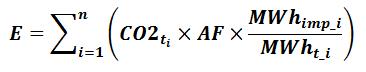
Where:
- E
- Total annual emissions of specified imported electricity from specified electricity generators that report GHG emissions to the Climate Registry, the US EPA using 40 CFR Part 75 or to Environment Canada under Section 46 of the Canadian Environmental Protection Act, 1999 S.C. 1999, c. 33 expressed in tonnes CO2e.
- CO2ti
- Total annual emissions from specified electricity generator i during the calendar year, expressed in tonnes CO2e as reported to The Climate Registry, US EPA, US Energy Information Administration or Environment Canada and where provided to the person.
- AF
- Adjustment factor calculated in accordance with ON.66.
- MWhimp_i
- Scheduled quantity of specified imported electricity imported from specified electricity generator i, recorded in all the e-tags from the specified electricity generator i, expressed in MWh. calculated in accordance with ON.65
- MWht_i
- Total annual megawatt-hours of net power generated by specified electricity generator i, expressed in MWh.
- n
- the number of specified electricity generators
- Calculation Methodology 2. Use Equation 60-2 to calculate the total annual emissions from specified imported electricity where
the specified electricity generator from which the specified imported electricity is received has not reported emissions to The Climate Registry, the US EPA using 40 CFR Part 75, US Energy Information Administration or to Environment Canada under Section 46 of the Canadian Environmental Protection Act, 1999 S.C. 1999, c. 33:
Equation 60-2:
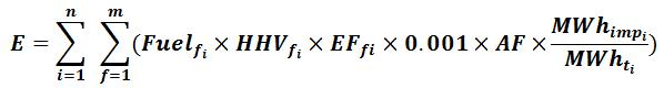
Where:
- E
- Total annual emissions from specified imported electricity from specified electricity generators that have not reported GHG emissions to the Climate Registry, the US EPA using 40 CFR Part 75 or to Environment Canada under Section 46 of the Canadian Environmental Protection Act, 1999 S.C. 1999, c. 33 expressed in tonnes CO2e.
- Fuelfi
- Total annual mass or volume of fuel “f” combusted by specified electricity generator “i” expressed in tonnes for solid fuel, volume in standard cubic meters for gaseous fuel, and volume in kilolitre for liquid fuel.
- HHVfi
- Higher heating value of fuel “f” consumed for electricity production in GJ per unit of fuel, or measured in accordance with ON.25 for specified electricity generating facility “i”.
- EFfi
- Fuel-specific default CO2e emission factor for fuel “f” from ON.20 expressed in kg CO2/GJ for specified electricity generating facility “i”.
- 0.001
- Conversion factor from kilograms to tonnes.
- AF
- Adjustment factor calculated in accordance with ON.66.
- MWhimpi
- Scheduled quantity of specified imported electricity from specified electricity generator i, recorded in all the e-tags from specified electricity generator i, expressed in MWh calculated in accordance with ON.65.
- MWhti
- Total annual megawatt-hours of net power generated by specified electricity generator “i”.
- n
- the number of specified electricity generators
- m
- the number of fuels
ON.64 Calculation of Unspecified Imported Electricity
The electricity importer shall use Equation 60-3 to calculate the emissions from unspecified imported electricity from each balancing authority area that sinks in Ontario:
Equation 60-3: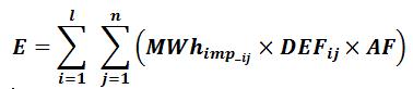
Where:
- E
- Total annual emissions of unspecified imported electricity expressed in tonnes CO2e.
- MWhimp_ij
- Annual scheduled quantity of unspecified imported electricity sinking in Ontario from each balancing authority area “i” in period “j”, based on the e-tag expressed in MWh calculated in accordance with ON.65.
- DEFij
- The default emission factor period “j” from each balancing authority “i” published by the Ontario Ministry of Energy in the document entitled “Default Emissions Factors for Ontario’s Cap and Trade Program”.
- i
- The balancing authority areas.
- j
- the peak or off peak period as the case may be.
- l
- The number of balancing authority areas.
- n
- The number of periods.
ON.65 Calculation of Imported Electricity
Equation 60-4:
MWhimp_i = ∑(MWhtotal_i − MWhwheel_i)
Equation 60-5:
MWhimp_ij = ∑∑(MWhtotal_ij − MWhwheel_ij)
Where:
- MWhimp_i
- Annual Scheduled quantity of specified imported electricity imported into Ontario by the electricity importer, expressed in MWh.
- MWhimp_ij
- Annual Scheduled quantity of unspecified imported electricity imported into Ontario by the electricity importer, expressed in MWh.
- MWhTotal_i
- Quantity of scheduled specified imported electricity recorded in each e-tag “i” that is imported into Ontario by the electricity importer, expressed in MWh.
- MWhwheel_i
- Scheduled quantity of specified imported electricity recorded in each e-tag “i” that is imported into Ontario by the electricity importer that is wheeled through Ontario, expressed in MWh.
- MWhTotal_ij
- Quantity of scheduled unspecified imported electricity recorded in each e-tag for balancing authority “i” and peak/off period “j” that is imported into Ontario by the electricity importer, expressed in MWh.
- MWhwheel_ij
- Scheduled quantity of unspecified imported electricity recorded in each e-tag for balancing authority “i” and peak/off period “j” that is imported into Ontario by the electricity importer that is wheeled through Ontario, expressed in MWh.
ON.66 Calculation of adjustment factor
An electricity importer that imports electricity from a designated jurisdiction or from a US State that is a member of and offered allowances for sale in an auction carried out by the Regional Greenhouse Gas Initiative in the calendar year, shall calculate the adjustment factor (AF) as follows.
Equation 60-5:
AF = 1 − (Pjurisdiction ⁄ POnt)Where:
- AF
- Adjustment factor
- Pjurisdiction
- Average sale price of emission allowances at auctions held during the calendar year by a designated jurisdiction where the import is from a US State that is a member of and offered allowances for sale in an auction carried out by the Regional Greenhouse Gas Initiative in the calendar year (in US dollar).
- POnt
- Average sale price of emission allowances at auctions held during the year by Ontario (in U.S. dollar).
- If a calculation for AF under paragraph (a) of ON.66 is less than zero, then the value of AF shall be equal to zero.
ON.270 Ferroalloy Production
ON.271 Activity Definition
For the purposes of this standard quantification method:
- Ferroalloy production
- has the same meaning as in the Regulation.
- Person
- means a person that engages in ferroalloy production.
ON.272 Greenhouse Gas Reporting Requirements
A person shall set out the following information, calculated for the calendar year using standard quantification methods ON.270 – ON.275, in an emission report prepared for a calendar year in respect of ferroalloy production at a facility:
- Process CO2 emissions from each electric arc furnace (EAF) used for the production of any ferroalloy listed in ON.271.
- Annual ferroalloy production (tonnes).
ON.273 Calculation of GHG Emissions
Quantify emissions in accordance with US EPA 40 CFR 98 Subpart K Section 98.113.
ON.274 Sampling, Analysis, and Measurement Requirements
Sampling, analysis and measurement requirements for this activity shall be done in accordance with US EPA 40 CFR 98 Subpart K Section 98.114.
ON.275 Procedures for Estimating Missing Data
Missing data requirements for this activity shall be estimated in accordance with US EPA 40 CFR 98 Subpart K Section 98.115.
ON.20 General Stationary Combustion
ON.21 Activity Definition
For the purposes of this standard quantification method:
- General stationary combustion
- has the same meaning as in the Regulation.
- Person
- means a person that engages in general stationary combustion.
ON.22 Greenhouse Gas Reporting Requirements
A person shall set out the following information, calculated for the calendar year using standard quantification methods ON.20 – ON.26, in an emission report prepared for a calendar year in respect of general stationary combustion at a facility:
- Annual greenhouse gas emissions from combustion of fuels, expressed in tonnes, reported as follows:
- Total CO2 emissions from the combustion of fossil fuels, reported by fuel type calculated in accordance with ON.23.
- Total CO2 emissions from the combustion of biomass, reported by fuel type calculated in accordance with ON.23.
- Total CH4 emissions, from the combustion of all fuels reported by fuel type calculated in accordance with ON.24.
- Total N2O emissions, from the combustion of all fuels reported by fuel type calculated in accordance with ON.24.
- Annual CO2 emissions from the use of sorbent calculated in accordance with ON.23(i).
- Annual quantity of fuel consumed, reported as follows:
- or gases, expressed in Sm3.
- For liquids, expressed in kilolitres.
- For non-biomass solids, expressed in tonnes.
- For biomass-derived solid fuels, expressed in bone dry tonnes.
- Annual weighted average carbon content of each fuel where carbon content is required to be measured for use in an equation.
- Annual weighted average high heat value of each fuel where high heat value is required to be measured for use in an equation.
- Annual amount of steam generated expressed in kilograms where equation 20-3 or 20-5 is used.
- Total Energy Input from the combustion of all non-biomass fuels, expressed in giga-joules.
- Total energy input from the combustion of all biomass fuels expressed in giga-joules.
- An attestation signed by the person or, where the person is not a natural person, an individual that is authorized to sign on behalf of the person confirming the total quantity of petroleum products received at the facility in the year from each supplier that supplied petroleum to the facility during the year.
- If electricity generation or cogeneration units are reporting under this Standard Quantification Method, report the cogeneration information required under ON.42(e) and ON.42(f).
- The annual production of the following products if applicable:
- Beer, in hundred litres.
- Coal tar feedstock processed, in tonnes.
- Fuel ethanol, in litres of absolute alcohol (excluding water, additives and denaturants).
- Gypsum panels, in thousand square feet.
- Hot rolled steel, in tonnes.
- Industrial ethanol, in litres absolute alcohol (excluding water, additives and denaturants).
- Polyethylene products, in tonnes.
- Raw sugar processed, in tonnes.
- Pulp products, in air dried tonnes.
- Paper products, in air dried tonnes.
ON.23 Calculation of CO2 Emissions
Choice of Method
- The person shall calculate CO2 emissions from the combustion of each fuel in the calendar year at an entire facility or on a unit by unit basis, as applicable, using one of the methodologies set out in (b) subject to the following rules:
- Calculation Methodology 1, contained in ON.23(b) may be used to calculate emissions from a facility that has:
- less than 25,000 tonnes of total CO2e emissions in respect of all Schedule 2 activities engaged in at the facility in the calendar year; or
- 25,000 tonnes or more of total CO2e emissions in respect of all Schedule 2 activities at the facility in the calendar year and the calculation is for emissions from the combustion of one of the following fuels:
- Natural gas with a high heat value of at least 36.3 and not greater than 40.98 MJ per cubic meter;
- Any of the fuels listed in Table 20-1a;
- Municipal solid waste combusted in a general stationary combustion unit that does not generate steam; or
- Any biomass fuel listed in Table 20-2 where the emissions associated with the combustion of that biomass are not required to be reported pursuant to any other standard quantification method for the calculation of emissions from Schedule 2 activities in the Regulation that would apply to the person for the calendar year in regards to which the report is being prepared.
- Notwithstanding ON.23(a)(1)(ii), a person mentioned in ON 23(a)(1)(ii) shall not use calculation methodology 1 to calculate emissions from:
- The combustion of a fuel for which the person:
- Routinely performs fuel sampling and analysis for the fuel high heat value; or
- Can obtain the results of fuel sampling and analysis for the fuel high heat value from the fuel supplier at the minimum frequency specified in ON.25(a), or at a greater frequency.
- The combustion of natural gas in a general stationary combustion unit with a rated heat input capacity greater than 264 GJ/hr (250 mmBtu/hr) that has operated for more than 1,000 hours in any of the three years prior to the calendar year that is the subject of the report.
- The combustion of a fuel for which the person:
- Calculation Methodology 2 contained in ON.23(c) may be used to calculate emissions by a person in the calendar year where the calculation is for emissions from the combustion of one of the following fuels:
- Natural gas with a high heat value of at least 36.3 and not greater than 40.98 MJ per cubic meter;
- Any of the fuels listed in Table 20-1a; and
- Any biomass fuel or municipal solid waste where the emissions associated with that combustion are not required to be reported pursuant to any other standard quantification method for the calculation of emissions from Table 2 activities that would apply to the person for the calendar year in regards to which the report is being prepared.
- Subject to (5) Calculation Methodologies 3 and 4 may be used to calculate emissions from the combustion of any type of fuel by a person in the calendar year in any general stationary combustion unit.
- Notwithstanding ON.23(a)(1) through (4) Calculation Methodology 4 shall be used to calculate all CO2 emissions from any general stationary combustion unit for which a CEMS that includes a flow monitor subsystem and CO2 concentration monitor is installed and:
- Is required by any applicable federal or provincial regulation; or
- Where not required by federal or provincial regulation, is the means by which the person elects to calculate CO2 emissions from any general stationary combustion unit.
- Calculation Methodology 1, contained in ON.23(b) may be used to calculate emissions from a facility that has:
Methods
Calculation Methodology 1. Use Equation 20-1 or 20-1a to calculate the annual CO2 emissions from the combustion of each type of fuel:
Equation 20-1:
CO2 = Fuel × (HHV × EF) × 0.001Equation 20-1a:
CO2 = Fuel × EFc × 0.001Where:
- CO2
- Annual CO2 emissions from the combustion of the specific fuel type, expressed in tonnes.
- Fuel
- Quantity of the fuel combusted in the calendar year, expressed in tonnes for solid fuels, standard cubic meters for gaseous fuels, and kilolitres for liquid fuels as measured in accordance with ON.25(b).
- HHV
- Default high heat value of the fuel contained in Table 20-1 or Table 20-1a, expressed in GJ per tonne of solid fuel, GJ per kilolitre of liquid fuel, or GJ per cubic meter of gaseous fuel.
- EF
- Fuel-specific default CO2 emission factor contained in Tables 20-1a, 20-2, 20-3, 20-5, or 20-7, expressed in kg of CO2 per GJ.
- EFc
- Fuel specific CO2 default emission factor from Tables 20-2, 20-3, or 20-5, expressed in kg of CO2 per tonne of solid fuel, kg of CO2 per kilolitre of liquid fuel, or kg of CO2 per cubic meter of gaseous fuel.
- 0.001
- Conversion factor from kilograms to tonnes.
Calculation Methodology 2: Calculate the annual CO2 mass emissions using Equation 20-2 and using a default fuel-specific CO2 emission factor and a high heat value provided by the supplier or measured by the person. For emissions from the combustion of biomass fuels and municipal solid waste, the person may instead elect to use the method shown in Equation 20-3.
Equation 20-2:
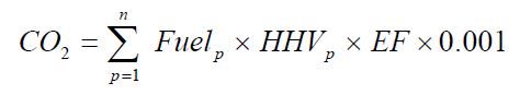
Where:
- CO2
- Annual CO2 emissions from the combustion of the specific fuel type, expressed in tonnes.
- n
- Number of required heat content measurements for the year as specified in ON.25.
- Fuelp
- Quantity of the fuel combusted during the measurement period “p”, expressed in tonnes for solid fuels, standard cubic meters for gaseous fuels, and kilolitres for liquid fuels as measured in accordance with ON.25(b).
- HHVp
- High heat value of the fuel for measurement period “p” calculated in accordance with ON.25(d) and (e), expressed in GJ per tonne of solid fuel, GJ per bone-dry tonne of biomass solid fuel, GJ per kilolitre of liquid fuel, or GJ per cubic meter for gaseous fuels.
- EF
- Fuel-specific default CO2 emission factor contained in Tables 20-1a, 20-2, 20-3, 20-5, or 20-7 expressed in kg of CO2 per GJ.
- 0.001
- Conversion factor from kilograms to tonnes.
Equation 20-3:
CO2 = Stream × B × EF × 0.001Where:
- CO2
- Annual CO2 emissions from solid biomass fuel or municipal solid waste combustion, expressed in tonnes.
- Steam
- Quantity of steam generated by biomass solid fuel or municipal solid waste combustion in the general stationary unit during the calendar year, expressed in tonnes.
- B
- Ratio of the boiler’s design rated heat input capacity to its design rated steam output capacity, expressed in GJ per tonne of steam.
- EF
- Default emission factor for solid biomass fuel or municipal solid waste, contained in Table 20-2 or Table 20-7 or a facility-specific emission factor determined in accordance with ON.25(a)(3)(ii), expressed in kg of CO2 per GJ.
- 0.001
- Conversion factor from kilograms to tonnes.
- Calculation Methodology 3. Use Equation 20-4, 20-5, 20-6 or 20-7 as applicable to calculate the annual CO2 emissions from the combustion of each type of fuel:
For a solid fuel, use Equation 20-4:
Equation 20-4:
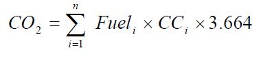
Where:
- CO2
- Annual CO2 emissions from the combustion of the specific solid fuel, expressed in tonnes.
- n
- Number of carbon content determinations for the year as specified in ON 25(a) and (j).
- Fueli
- Quantity of the solid fuel combusted in measurement period “i”, expressed in tonnes as measured in accordance with ON.25(b).
- CCi
- Carbon content of the solid fuel, from the fuel analysis results for measurement period “i” calculated in accordance with ON.25(j), expressed in tonnes of C per tonne of fuel.
- 3.664
- Ratio of molecular weights, CO2 to carbon.
For solid biomass fuels or municipal solid waste in a general stationary combustion unit that produces steam, use Equation 20-3 or 20-5:
Equation 20-5:
CO2 = Steam × EF × 0.001Where:
- CO2
- Annual CO2 emissions from the combustion of solid biomass fuel or municipal solid waste, expressed in tonnes.
- Steam
- Quantity of steam generated by solid biomass fuel or municipal solid waste combustion during the calendar year, expressed in tonnes.
- EF
- Measured emission factor for solid biomass fuel or municipal solid waste, expressed in kg of CO2 per tonne of steam calculated in accordance with ON.25(a) and (j).
- 0.001
- Conversion factor from kilograms to tonnes.
For a liquid fuel, use Equation 20-6:
Equation 20-6:
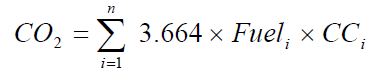
Where:
- CO2
- Annual CO2 emissions from the combustion of the specific liquid fuel, expressed in tonnes.
- n
- Number of required carbon content determinations for the calendar year, as specified in ON.25(a).
- Fueli
- Volume of the liquid fuel combusted in measurement period “i” as specified in ON.25(b), expressed in kilolitres.
- CCi
- Carbon content of the liquid fuel, from the fuel analysis results for measurement period “i” calculated in accordance with ON.25(j), expressed in tonnes of C per kilolitre of fuel.
- 3.664
- Ratio of molecular weights, CO2 to carbon.
For a gaseous fuel, use Equation 20-7:
Equation 20-7:
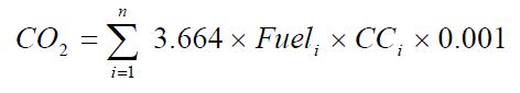
Where:
- CO2
- Annual CO2 mass emissions from combustion of the specific gaseous fuel, expressed in tonnes.
- n
- Number of carbon content determinations for the calendar year, as specified in ON.25(a).
- Fueli
- Volume of fuel combusted in period “i”, expressed in Rm3 at reference temperature and pressure conditions as used by the facility, or expressed in kg if a mass flow meter is used as measured in accordance with ON.25(b).
- CCi
- Carbon content of the gaseous fuel, from the fuel analysis results for the period “i” calculated in accordance with ON.25(i), expressed in kg of C per Rm3 of fuel or kg of C per kg of fuel if a mass flow meter is used.
- 3.664
- Ratio of molecular weights, CO2 to carbon.
- 0.001
- Conversion factor from kg to tonnes.
- Calculation Methodology 4: Calculate the annual CO2 emissions from the combustion of each type of fuel combusted in a general stationary combustion unit, by using data from CEMS calibrated and operated in accordance with ON.25(n) through (p) and the following rules:
- The person shall report CO2 emissions for the calendar year, expressed in tonnes based on the sum of hourly CO2 emissions over the year.
- Where another standard quantification method requires the quantification of process emissions using data from CEMS in accordance with this standard quantification method, unless the other method specifies otherwise, the person shall not be required to quantify:
- Process emission separately from combustion emissions for a unit where the data from CEMS is used to quantify both process and combustion emissions; or
- Emissions from different fossil fuels separately in a unit where only fossil fuels are co-fired, though the fuel types used still need to be included in the report.
- Notwithstanding ON.23(a)(4) emissions from the combustion of any fuel not listed in Tables 20-1 through 20-7; or in Table C-1 or C-2 in US EPA 40 CFR Part 98, Subpart C are not required to be reported if the emissions from the combustion of the fuel does not exceed 0.5% of total facility emissions.
- Notwithstanding ON.23(a) through (f) the person may calculate emissions from the combustion of volatile organic compounds in thermal destruction systems using engineering methods.
- CO2 emissions from combustion of mixtures of biomass or biomass fuel and fossil fuel. For the purposes of calculating biomass-related CO2 emissions from general stationary combustion units mentioned in ON.23(a)(1) through (4) that combust a mixture of biomass fuels with another type of fuel or a fuel containing biomass the person shall use one of Calculation Methodologies 1, 2, 3 or 4 substituting relevant information from the following:
- Determine the mass of biomass combusted by:
- Using company records and Calculation Methodologies 1, 2 or 3; or
- Where the fuel is a premixed fuel that contains biomass and fossil fuels, using the best available information to determine the mass of biomass fuels and documenting the information and procedure used.
- Where calculation methodology 4 is used and the unit combusts biomass fuels that do not include waste-derived fuels, use Calculation Methodologies 1, 2, or 3 to calculate the annual CO2 mass emissions from the combustion of fossil fuels and then calculate biomass fuel emissions by subtracting the fossil fuel-related emissions from the total CO2 emissions determined using Calculation Methodology 4.
- Where the person combusts fuels or fuel mixtures for which the biomass fraction is unknown or cannot be documented, or a biomass fuel for which a CO2 emission factor is not provided in Table 20-2, the person shall use ASTM D6866 in accordance with ON.25(m).
- Notwithstanding ON.25(h)(1) through (3) a person is not required to calculate biomass-related CO2 emissions from the combustion of fuels that contain less than 5 per cent biomass by weight or waste-derived fuels that are less than 30 per cent by weight of total fuels combusted in calendar year.
Where a person uses Calculation Methodology 1 to calculate CO2 emissions from solid biomass fuel, the person may elect to use Equation 20-8 to calculate the biomass-related emissions from the combustion of that fuel:
Equation 20-8:
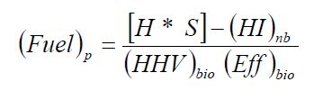
Where:
- Determine the mass of biomass combusted by:
- (Fuel)p
- Quantity of biomass consumed during the measurement period “p”, expressed in tonnes per year or tonnes per month, as applicable.
- H
- Average enthalpy of the boiler steam for the measurement period, expressed in GJ per tonne.
- S
- Quantity of boiler steam produced for measurement period “p”, expressed in tonnes/month or tonnes/year, as applicable.
- (HI)nb
- Heat input from co-fired fossil fuels and non-biomass-derived fuels for the measurement period, based on company records of fuel usage and HHV values contained in ON.20 or measured HHV values, expressed in GJ per month or GJ per year, as applicable.
- (HHV)bio
- HHV values contained in Table 20-1 or measured HHV of the biomass fuel, expressed in GJ per tonne.
- (Eff)bio
- Efficiency of biomass-to-energy conversion, expressed as a decimal fraction.
- Calculation of CO2 from the use of sorbent.
- Where a person operates a fluidized bed boiler that is equipped with a wet flue gas desulphurization system, or uses other acid gas emission controls with sorbent injection, the person shall calculate CO2 emissions using:
- Data from CEMS; or
Where CEMS are not required to be used, using Equation 20-9:
Equation 20-9:
CO2 = S × R × (MWCO2 ⁄ MWS)
- Where a person operates a fluidized bed boiler that is equipped with a wet flue gas desulphurization system, or uses other acid gas emission controls with sorbent injection, the person shall calculate CO2 emissions using:
- CO2
- Annual CO2 emissions from the use of sorbent, expressed in tonnes.
- S
- Quantity of limestone or other sorbent used in the calendar year, from company records, expressed in tonnes.
- R
- The calcium-to-sulphur stoichiometric ratio which has a value of 1.00, or is determined based on actual sorbent used.
- MWCO2
- Molecular weight of carbon dioxide.
- MWS
- Molecular weight of sorbent.
- The annual CO2 emissions for all units shall be the sum of the CO2 emissions for each type of fuel from the calculations under paragraphs (b), (c), (d), (e) and (i) of ON.23
ON.24 Calculation of CH4 and N2O Emissions
Choice of Method
- The person shall calculate CH4 and N2O emissions from the combustion of any fuel listed in Tables 20-2, 20-3, 20-4 and 20-6 in the calendar year using one or more of the following calculation methodologies as applicable:
- Calculation Methodology 5 contained in ON.24(c) may only be used to calculate emissions from a facility that combusts:
- Natural gas with a high heat value of at least 36.3 and not greater than 40.98 MJ per cubic meter;
- Any fuel listed in Table 20-1a; or
- Any biomass fuel listed in Table 20-2.
- Calculation Methodology 6 contained in ON.24(d) may be used to calculate emissions from any general stationary combustion unit that combusts any type of fuel.
- Calculation Methodology 7 contained in ON.24(e) may only be used to calculate emissions from a general stationary combustion unit that calculates CO2 emissions using Equations 20-3 and 20-5.
- Notwithstanding ON.24(a)(1) through (3) Calculation Methodology 8 ON.24(f) shall be used to calculate all CH4 and N2O emissions from any general stationary combustion unit for which Calculation Methodology 4 is used and heat input is monitored on a year round basis.
- Notwithstanding the above, a person at a facility that has total reported CO2e emissions below 25,000 tonnes per year from all Table 2 activities at the facility may elect to use any of the above methods to calculate emission from the combustion of any fuel listed in Tables 20-2, 20-3, 20-4 and 20-6.
- Calculation Methodology 5 contained in ON.24(c) may only be used to calculate emissions from a facility that combusts:
- The person may elect to use engineering estimates to calculate the annual CH4 and N2O emissions for fuels that are not listed in Tables 20-2, 20-3, 20-4 and 20-6.
Methods
Calculation Methodology 5. Use Equations 20-10 or 20-11 as applicable to calculate the annual CH4 and N2O emissions from the combustion of each fuel.
For non-coal fuel, use Equation 20-10:
Equation 20-10:
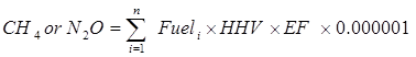
For coal, use Equation 20-11:
Equation 20-11:
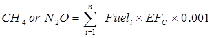
Where:
- E
- Annual CH4 or N2O emissions from a specific fuel type, expressed in tonnes.
- Fueli
- Quantity of the fuel combusted during measurement period “i”, expressed in tonnes for solid fuels, standard cubic meters for gaseous fuels, and kilolitres for liquid fuels.
- HHV
- Default high heat value for fuel type “i” contained in Table 20-1 or 20-1a expressed in GJ per tonne of solid fuel, GJ per kilolitre of liquid fuel, or GJ per cubic meter of gaseous fuel.
- EF
- Default CH4 or N2O emission factor for fuel type contained in Tables 20-2 or 20-4, as applicable, expressed in grams CH4 or N2O per GJ or an equipment-specific emission factor contained in US EPA AP-42 as appropriate.
- EFc
- Default CH4 or N2O emission factor for each coal type contained in Table 20-6, expressed in grams CH4 or N2O per kg of coal or an equipment-specific emission factor
- 0.000001
- Conversion factor from grams to tonnes.
- 0.001
- Conversion factor from g/kg to tonnes/tonne.
Calculation Methodology 6. Use Equation 20-12 or 20-13 as applicable to calculate the annual CH4 and N2O emissions from the combustion of each fuel.
For non-coal fuel, use Equation 20-12:
Equation 20-12:
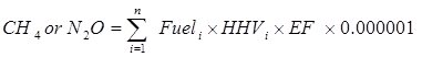
For coal, use Equation 20-13:
Equation 20-13:
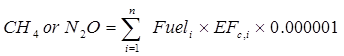
Where:
- CH4 or N2O
- Annual CH4 or N2O emissions from a specific fuel type, expressed in tonnes.
- Fueli
- Quantity of fuel combusted during measurement period “i”, expressed in tonnes for solid fuels, standard cubic meters for gaseous fuels, and kilolitres for liquid fuels.
- HHVi
- High heat value measured directly or provided by the fuel supplier for the specified fuel type, expressed as GJ per tonne of solid fuel, GJ per kilolitre of liquid fuel, or GJ per cubic meter of gaseous fuel in accordance with ON.25(d) and (e).
- EFi
- Default CH4 or N2O emission factor for each fuel type contained in Table 20-2 or 20-4, as applicable, expressed in grams CH4 or N2O per GJ or an equipment-specific emission factor contained in US EPA AP-42 as appropriate.
- EFc
- CH4 or N2O emission factor for each coal type either measured directly or provided by the fuel supplier, expressed in grams CH4 or N2O per tonne of coal.
- 0.000001
- Conversion factor from grams to tonnes.
Calculation Methodology 7. Use Equation 20-15 to calculate the annual CH4 and N2O emissions from the combustion of biomass fuel or municipal solid waste.
Equation 20-14:
CH4 or N2O = Steam × B × EF × 0.000001Where:
- CH4 or N2O
- Annual CH4 or N2O emissions from the combustion of biomass fuel or municipal solid waste, expressed in tonnes.
- Steam
- Quantity of steam generated by biomass or municipal solid waste combustion during the calendar year, expressed in tonnes.
- B
- Ratio of the boiler’s design rated heat input capacity to its design rated steam output, expressed in GJ per tonne of steam.
- EF
- Default emission factor for CH4 or N2O, contained in Tables 20-2, 20-4, 20-6 or 20-7, as applicable, expressed in grams per GJ.
- 0.000001
- Conversion factor from grams to tonnes.
Calculation Methodology 8. Use Equation 20-15.
Equation 20-15:
CH4 or N2O = 0.000001 × HIA × EFWhere:
- CH4 or N2O
- Annual CH4 or N2O emissions from the combustion of a specific type of fuel, expressed in tonnes.
- HIA
- Cumulative annual heat input from each type of fuel, expressed in GJ in accordance with ON.25(g).
- EF
- Default fuel-specific emission factor for CH4 or N2O, contained in Tables 20-2, 20-4 or 20-6, as applicable, expressed in grams per GJ, grams per kilogram of solid fuel, grams of kiloliter for liquid fuel and grams per cubic meter of gaseous fuel.
- 0.000001
- Conversion factor from grams to tonnes.
- Where Calculation Methodologies 5 to 8 require the use of an emissions factor the person may elect to use facility-specific emission factors derived from source tests conducted annually to calculate CH4 or N2O emissions using Equation 20-11.
- When multiple fuels are combusted during the calendar year, sum the fuel-specific results from the Equations in ON.24 to obtain the total annual CH4 and N2O emissions, expressed in tonnes.
ON.25 Sampling, Analysis, and Measurement Requirements
Fuel Sampling Frequency Requirements
- The person required to obtain fuel samples pursuant to this standard quantification method shall do so by conducting fuel sampling or obtaining fuel sampling results from the fuel supplier in accordance with the following rules:
- Fuel samples shall be taken at a location in the fuel handling system that provides a representative sample of the fuel combusted.
- Fuel samples shall be obtained and analysis performed at the following minimum frequencies:
- Once for each shipment or delivery of coal.
- Once for each new fuel shipment or delivery, or quarterly for each of the fuels listed in Table 20-1a.
- Semiannually for natural gas.
- Quarterly for liquid fuels other than fuels listed in Table 20-1a.
- Quarterly for gases derived from biomass including landfill gas and biogas from wastewater treatment or agricultural processes.
- Daily for gaseous fuels other than natural gas, gases derived from biomass, and biogas in order to determine the carbon content and molecular weight of the fuel if the necessary equipment is in place to make these measurements.
- Weekly for gaseous fuels other than natural gas, gases derived from biomass, and biogas, where the necessary equipment is not in place to make daily measurements.
- Monthly composite samples of solid fuels other than coal and waste-derived fuels shall be taken in accordance with the following:
- The sample shall be a composite sample of weekly samples of equal mass taken during the month.
- Sampling shall be done at a location after all fuel treatment operations but before fuel combustion.
- Samples shall be representative of the fuel chemical and physical characteristics immediately prior to combustion.
- Sub-samples shall be collected at a day and time when the fuel consumption rate is representative and unbiased.
- The monthly composite sample shall be homogenized and well mixed prior to withdrawal of a sample for analysis.
- One in every twelve composite samples shall be randomly selected for additional analysis of its discrete constituent samples.
- Where the fuel being sampled is a biomass or waste-derived fuel, the following sampling frequencies may apply in lieu of those contained in ON.25(a)(2)(iv), (v) and (viii):
- If CO2 emissions are calculated using Equation 20-2 or 20-4, the facility-specific high heat value or carbon content is determined annually.
- If CO2 emissions from the combustion of biomass fuels or municipal solid waste are calculated using Equation 20-5 , the person shall:
- Adjust the emission factor no less frequently than every third year, through a stack test measurement of CO2; and
- Use the applicable ASME Performance Test Code to determine heat input from all heat outputs, including the steam, flue gases, ash and losses.
Fuel Consumption Monitoring Requirements
- The person required to monitor fuel consumption pursuant to this standard quantification method shall do so by monitoring in accordance with the following rules:
Fuel consumption shall be determined using:
- Direct measurement; or
- Measured stock changes in fuel calculated in accordance with Equation 20-16 expressed in MJ, litres, million standard cubic meters, tonnes or bone dry tonnes as appropriate.
Equation 20-16:
Fuel Consumption in the Report Year = Total Fuel Purchases − Total Fuel Sales + Amount Stored at Beginning of Year − Amount Stored at Year End- For the purposes of calculating total fuel purchases of natural gas, the calculation can be based on the recorded fuel purchases or sales invoices in the calendar year for which the report is being prepared without accounting for fuel recorded in those recorded purchases or invoices that may be used in the previous or subsequent year.
- Where fuel consumption is measured in MJ, the person shall convert to mass or volume using heat content values that are either provided by the supplier, measured by the facility, or contained in Table 20-1.
- For fuel oil, tank drop measurements may also be used to calculate fuel consumption.
- A person required to determine quantities of liquid fuel pursuant to this method may elect to use a volumetric flow meter or a fuel flow meter that measures mass flow rates and is used in accordance with the following:
- Fuel density shall be used to convert the readings to volumetric flow rates; and
- Density shall be measured at the same frequency as the carbon content, using one of the following methods:
- Any applicable method listed in the Technical Reference Document section of this Guideline;
- The most appropriate method published by a consensus-based standards organization; or
- Where no appropriate method is published by a consensus-based standards organization, using industry standard methods, noting where such methods are used and what methods are used.
Notwithstanding ON.25(b)(5)(ii), a person that uses Calculation Methodologies 1 or 2 may elect to use the following default density values for fuel oil:
Fuel Oil Default Density Values Fuel Oil No.1 Oil No.2 Oil No.6 Oil Default Density, kg/L 0.81 0.86 0.97
- Calibration requirements
- A person required to determine quantities of fuel in accordance with this method shall calibrate all fuel oil and gas flow meters except for meters on the natural gas delivery system (including gas billing meters) prior to the first calendar year for which GHG emissions are required to be reported pursuant to this method using calibration or verification procedures specified by the flow meter manufacturer or Measurement Canada.
- A person required to determine quantities of fuel in accordance with this method shall recalibrate all fuel flow meters:
- At least once every three years;
- Upon replacement of a previously calibrated meter; or
- At the minimum frequency specified by the manufacturer or under the laws and regulations of Measurement Canada.
- A person required to determine quantities of fuel in accordance with this method shall calibrate orifice, nozzle, and venturi flow meters using in-situ calibration of the differential pressure (delta-P), total pressure, and temperature transmitters.
Fuel Heat Content Monitoring Requirements
- A person required to monitor heat content of gaseous fuels in accordance with this method shall do so in accordance with the following rules:
- Using any applicable analytical methods listed in the Technical Reference Document section of this Guideline;
- Using the most appropriate method published by a consensus-based standards organization; or
- Where no appropriate method is published by a consensus-based standards organization, using industry standard methods, noting where such methods are used and what methods are used.
- For natural gas, using methods and requirements in accordance with the requirements under the laws and regulation of Measurement Canada for electricity and gas.
- Using on-line instrumentation that determines heating value accurate to within ± 5.0 per cent and, where such instrumentation provides only low heat value, the person shall convert the value to high heat value using Equation 20-17 in accordance with the following:
- When the heating value of natural gas is being measured the value of CF shall be 1.11.
- Where the heating value of refinery fuel gas or mixtures of refinery fuel gas is being measured, the CF shall be determined as a fuel-specific weekly average CF using the following:
- Concurrent LHV and HHV measurements determined by on-line instrumentation or laboratory analysis as part of the daily carbon content determination; or
The HHV/LHV ratio obtained from the laboratory analysis of the daily samples.
Equation 20-17:
HHV = LHV × CFWhere:
- HHV
- Fuel or fuel mixture high heat value, expressed in MJ per Sm3.
- LHV
- Fuel or fuel mixture low heat value, expressed in MJ per Sm3.
- CF
- Conversion factor.
- The person shall conduct fuel heat content monitoring of all solid and liquid fuel, including biomass and waste derived fuels, in accordance with the following:
- Using any applicable analytical methods listed in the Technical Reference Document section of this Guideline;
- Using the most appropriate method published by a consensus-based standards organization; or
- Where no appropriate method is published by a consensus-based standards organization, using industry standard methods, noting where such methods are used and what methods are used.
- The person required to use Equation 20-15 shall derive the cumulative annual heat input (HIa): estimated from the best available information such as fuel feed rate measurements, fuel heating values, engineering analysis, or information used for accounting purposes.
Use Equation 20-18 to calculate the weighted annual average heat content of the fuel, if the measured heat content is used to calculate CO2 emissions.
Equation 20-18:
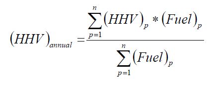
Where:
- (HHV)annual
- Weighted annual average high heat value of the fuel, expressed in GJ per tonne of solid fuel, GJ per kilolitre of liquid fuel, or GJ per cubic meter of gaseous fuel.
- (HHV)p
- High heat value of the fuel, for measurement period “p”, expressed in GJ per tonne of solid fuel, GJ per kilolitre of liquid fuel, or GJ per cubic meter of gaseous fuel.
- (Fuel)p
- Quantity of the fuel combusted during measurement period “p”, expressed in tonnes for solid fuels, standard cubic meters for gaseous fuels, and kilolitres for liquid fuels.
- n
- Number of measurement periods in the calendar year that fuel is combusted in the unit.
Fuel Carbon Content Monitoring Requirements
- The person required to determine fuel carbon content and either molecular weight or molar fraction for gaseous fuels shall use the results of fuel sampling and analysis received from the fuel supplier or results determined by the person using the following:
- Any applicable analytical methods listed in the Technical Reference Document section of this Guideline;
- The most appropriate method published by a consensus-based standards organization;
- Where no appropriate method is published by a consensus-based standards organization, using industry standard methods, noting where such methods are used and what methods are used; or
- For natural gas, using methods and requirements in accordance with the requirements under the laws and regulation of Measurement Canada for electricity and gas.
- The person required to determine the carbon content of solid or liquid fuel including biomass and waste derived fuels shall use the results of fuel sampling and analysis received from the fuel supplier or results determined by the person using the following.
- Any applicable analytical methods listed in the Technical Reference Document section of this Guideline;
- The most appropriate method published by a consensus-based standards organization; or
- Where no appropriate method is published by a consensus-based standards organization, using industry standard methods, noting where such methods are used and what methods are used.
- If on-line instrumentation is used, the equipment necessary to perform daily sampling and analysis of carbon content and molecular weight shall determine fuel carbon content accurate to ± 5 per cent.
The person required to calculate the weighted annual average carbon content of fuel pursuant to this method shall do so using Equation 20-19 if measured carbon content is used to calculate CO2 emissions.
Equation 20-19:
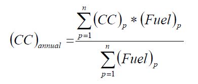
Where:
- (CC)annual
- Weighted annual average carbon content of the fuel, expressed in tonnes of C per tonne of solid fuel, tonnes of C per kilolitre of liquid fuel, or kg of C per kg of gaseous fuel.
- (CC)p
- Carbon content of the fuel, for measurement period “p” (expressed in tonnes of C per tonne of solid fuel, tonnes of C per kilolitre of liquid fuel, or kg of C per kg of gaseous fuel.
- (Fuel)p
- Quantity of the fuel combusted during measurement period “p”, expressed in tonnes for solid fuels, standard cubic meters for gaseous fuels, and kilolitres for liquid fuels.
- n
- Number of measurement periods in the calendar year that fuel is combusted in the unit.
- The person required to use ASTM D6866 under ON.23(h)(3) shall use the following to determine the biomass carbon fraction of the fuel or fuel mixture.
- Conduct ASTM D6866 analysis on a representative fuel sample at least once every three months.
- Conduct ASTM D6866 analysis on a representative exhaust gas sample at least once every three months. The exhaust gas samples shall be collected over at least 24 consecutive hours following the standard practice specified by ASTM D7459.
- If municipal solid waste is combusted, the ASTM D6866 analysis shall be performed on the exhaust gas stream.
- If there is a common fuel source to multiple units at the facility, the person may elect to conduct ASTM D6866 testing for only one of the units sharing the common fuel source.
Continuous Emissions Monitors and Source Testing
- The person that uses Calculation Methodology 4 under ON.23(e) shall select and operate the CEMS in accordance with EPS 1/PG/7.
- Notwithstanding the requirement in EPS 1/PG/7 to use a CO2 concentration monitor, a person using Calculation Methodology 4 may use an oxygen (O2) concentration monitor in lieu of a CO2 concentration monitor in a CEMS installed before January 1, 2017, to determine hourly CO2 concentrations, if:
- The effluent gas stream monitored by the CEMS consists solely of combustion products;
- Only one or more of the following fuels are combusted in the unit: coal, biomass, petroleum coke, oil, natural gas, propane, butane, wood bark, or wood residue;
- The unit does not combust waste derived fuels other than wood bark or wood residue; and
- where the CEMS is used to monitor emissions from the combustion of biomass fuel other than wood bark or wood residue, annual source testing demonstrates that the use of O2 concentrations to calculate CO2 concentrations meets all the requirements of EPS 1/PG/7 including the Relative Accuracy Test Audit (RATA).
- The person required to conduct source or performance testing shall do so as follows:
- Where a facility-specific emission factor for CH4 and N2O is used it shall be updated annually.
- Where a facility-specific emission factor determined in accordance with Equation 20-3 or 20-5 is used, the factor shall be updated at least every third year.
- Fuel Analytical Data Capture. Where a person is required to collect fuel analytical data, the data capture rate shall be 80 per cent or more. The person shall measure the quantity of products identified in ON.22(k). Equipment used to measure the production quantity shall be:
- calibrated according to the manufacturer’s instructions and
- maintained an accuracy of plus or minus 5%.
ON.26 Procedures for Estimating Missing Data
Unavailable analytical Data
- Whenever analytical data relating to sampling is unavailable, the person shall, using the methods prescribed in ON.25, re-analyze the original sample, a backup sample or a replacement sample for the same measurement and sampling period.
Determination of quantity
- Whenever sampling and measurement data required by ON.23 (a), (b) and (c) and ON.24 (a), (b) and (c) for the calculation of emissions is missing the person shall ensure that the data is replaced using the following missing data procedures:
- When the missing data concerns high heat value, carbon content, molecular mass, CO2 concentration, water content or any other data sampled, the person shall:
Determine the sampling or measurement rate using Equation 20-20:
Equation 20-20:
R = QSAct ⁄ QSRequired
Where:
- When the missing data concerns high heat value, carbon content, molecular mass, CO2 concentration, water content or any other data sampled, the person shall:
- R
- Sampling or measurement rate that was used, expressed as a percentage
- QSAct
- Quantity of actual samples or measurements obtained by the person
- QSRequired
- Quantity of samples or measurements required under ON.25
- Replace the missing data as follows,
- If R ≥ 0.9: replace the missing data by the arithmetic mean of the sampling or measurement data from immediately before and after the missing data period. If no data is available from before the missing data period, the person shall use the first available data from after the missing data period.
- If 0.75 ≤ R < 0.9: replace the missing data by the highest data value sampled or analyzed during the calendar year for which the calculation is made.
- If R < 0.75: replace the missing data by the highest data value sampled or analyzed during the 3 preceding years.
- When the missing data concerns stack gas flow rate, fuel consumption or the quantity of sorbent used, the replacement data shall be generated from best estimates based on all of the data relating to the processes.
- A person who uses CEMS shall determine the replacement data using the procedure in EPS 1/PG/7 or the following method:
- When the missing data is data measured by the CEMS;
Determine the sampling or measurement rate using Equation 20-21:
Equation 20-21:
R = HSAct ⁄ HSRequired
Where:
- When the missing data is data measured by the CEMS;
- R
- Sampling or measurement rate, that was used, expressed as a percentage
- HSAct
- Quantity of actual samples or measurements obtained by the person
- HSRequired
- Quantity of samples or measurements required under ON.25
- Replace the missing data as follows,
- If R ≥ 0.9: replace the missing data by the arithmetic mean of the sampling or measurement data from immediately before and after the missing data period. If no data is available from before the missing data period, the person shall use the first available data from after the missing data period.
- If 0.75 ≤ R < 0.9: replace the missing data by the highest data value sampled or analyzed during the calendar year for which the calculation is made.
- If R < 0.75: replace the missing data by the highest data value sampled or analyzed during the 3 preceding years.
| Liquid Fuels | High Heat Value (GJ/kl) |
|---|---|
| Asphalt & Road Oil | 44.46 |
| Aviation Gasoline | 33.52 |
| Diesel | 38.3 |
| Aviation Turbo Fuel | 37.4 |
| Kerosene | 37.68 |
| Propane¹ | (see Table 20-2) |
| Ethane | (see Table 20-2) |
| Butane | (see Table 20-2) |
| Lubricants | 39.16 |
| Motor Gasoline - Off-Road | 35 |
| Light Fuel Oil | 38.8 |
| Residual Fuel Oil (#5 & 6) | 42.5 |
| Crude Oil | 38.32 |
| Naphtha | 35.17 |
| Petrochemical Feedstocks | 35.17 |
| Petroleum Coke - Refinery Use | 46.35 |
| Petroleum Coke - Upgrader Use | 40.57 |
| Ethanol (100%) | 21.04 |
| Biodiesel (100%) | 32.06 |
| Rendered Animal Fat | 31.05 |
| Vegetable Oil | 30.05 |
| Solid Fuels | High Heat Value (GJ/tonne) |
|---|---|
| Anthracite Coal | 27.7 |
| Bituminous Coal | 26.33 |
| Foreign Bituminous Coal | 29.82 |
| Sub-Bituminous Coal | 19.15 |
| Lignite | 15 |
| Coal Coke | 28.83 |
| Solid Wood Waste (dry, 0% moisture) | 19.2 |
| Spent Pulping Liquor | 14 |
| Municipal Solid Waste | 11.57 |
| Tires | 31.18 |
| Agricultural byproducts | 8.6 |
| Solid byproducts | 26.93 |
| Gaseous Fuels | High Heat Value (GJ/m³) |
|---|---|
| Natural Gas | 0.038 |
| Coke Oven Gas | 0.01914 |
| Still Gas - Refineries | 0.03608 |
| Still Gas - Upgraders | 0.04324 |
| Landfill Gas (captured methane) | 0.0359 |
| Other Biogas (captured methane) | 0.0359 |
¹ The default high heat value for propane is only for the pure gas species. For the product commercially sold as propane, the value for liquefied petroleum gas in Table 20-1a should be used instead.
| Fuel Type: Petroleum Products | Default High Heat Value: GJ/kilolitre | Default CO2 Emission Factor: kg CO2⁄GJ |
|---|---|---|
| Distillate Fuel Oil No. 1 | 38.78 | 69.16 |
| Distillate Fuel Oil No. 2 | 38.5 | 70.18 |
| Distillate Fuel Oil No. 4 | 40.73 | 71.10 |
| Kerosene | 37.68 | 71.18 |
| Propane or Liquefied petroleum gases (LPG) | 25.66 | 59.65 |
| Propane (pure, not mixtures of LPGs)¹ | 25.48 | 59.59 |
| Propylene | 25.39 | 62.46 |
| Ethane | 18.91 | 56.49 |
| Ethylene | 27.9 | 56.49 |
| Isobutane | 27.61 | 61.55 |
| Isobutylene | 28.73 | 64.16 |
| Butane | 28.80 | 60.83 |
| Butylene | 28.73 | 61.39 |
| Natural Gasoline | 30.69 | 63.29 |
| Motor Gasoline | 34.87 | 65.4 |
| Aviation Gasoline | 33.52 | 65.49 |
| Kerosene-Type Jet Fuel | 37.66 | 71.22 |
¹ The default factors for “propane” are only for the pure gas species. For the product commercially sold as propane, the values for LPG should be used instead.
| Fuel Type: Liquid Fuels | CO2 Emission Factor (kg/kL) | CO2 Emission Factor (kg/GJ) | CH4 Emission Factor (g/L) | CH4 Emission Factor (g/GJ) | N20 Emission Factor (g/L) | N20 Emission Factor (g/GJ) |
|---|---|---|---|---|---|---|
| Aviation Gasoline | 2342 | see Table 20-1a | 2.2 | 65.63 | 0.23 | 6.862 |
| Diesel | 2663 | 69.53 | 0.133 | 3.473 | 0.4 | 10.44 |
| Aviation Turbo Fuel | 2534 | see Table 20-1a | 0.08 | 2.139 | 0.23 | 6.15 |
| Kerosene - Electric Utilities | 2534 | see Table 20-1a | 0.006 | 0.159 | 0.031 | 0.823 |
| Kerosene - Industrial | 2534 | see Table 20-1a | 0.006 | 0.159 | 0.031 | 0.823 |
| Kerosene - Producer Consumption | 2534 | see Table 20-1a | 0.006 | 0.159 | 0.031 | 0.823 |
| Kerosene - Forestry, Construction, and Commercial/Institutional | 2534 | see Table 20-1a | 0.026 | 0.69 | 0.031 | 0.823 |
| Propane - Residential | 1510 | see Table 20-1a | 0.027 | 1.067 | 0.108 | 4.267 |
| Propane - All other uses | 1510 | see Table 20-1a | 0.024 | 0.948 | 0.108 | 4.267 |
| Ethane | 976 | see Table 20-1a | N/A | N/A | N/A | N/A |
| Butane | 1730 | see Table 20-1a | 0.024 | 0.844 | 0.108 | 3.797 |
| Lubricants | 1410 | 36.01 | N/A | N/A | N/A | N/A |
| Motor Gasoline – Off-Road | 2289 | 65.4 | 2.7 | 77.14 | 0.05 | 1.429 |
| Light Fuel Oil - Electric Utilities | 2725 | 70.23 | 0.18 | 4.639 | 0.031 | 0.799 |
| Light Fuel Oil - Industrial | 2725 | 70.23 | 0.006 | 0.155 | 0.031 | 0.799 |
| Light Fuel Oil - Producer Consumption | 2643 | 68.12 | 0.006 | 0.155 | 0.031 | 0.799 |
| Light Fuel Oil - Forestry, Construction, and Commercial/Institutional | 2725 | 70.23 | 0.026 | 0.67 | 0.031 | 0.799 |
| Residual Fuel Oil (#5 & 6) - Electric Utilities | 3124 | N/A | 0.034 | 0.8 | 0.064 | 1.506 |
| Residual Fuel Oil (#5 & 6) - Industrial | 3124 | N/A | 0.12 | 2.824 | 0.064 | 1.506 |
| Residual Fuel Oil (#5 & 6) - Producer Consumption | 3158 | N/A | 0.12 | 2.824 | 0.064 | 1.506 |
| Residual Fuel Oil (#5 & 6) - Forestry, Construction, and Commercial/Institutional | 3124 | N/A | 0.057 | 1.341 | 0.064 | 1.82 |
| Naphtha | 625 | 17.77 | N/A | N/A | N/A | N/A |
| Petrochemical Feedstocks | 500 | 14.22 | N/A | N/A | N/A | N/A |
| Petroleum Coke - Refinery Use | 3826 | 82.55 | 0.12 | 2.589 | 0.0265 | 0.572 |
| Petroleum Coke - Upgrader Use | 3494 | 86.12 | 0.12 | 2.958 | 0.0231 | 0.569 |
| Biomass | CO2 Emission Factor (kg/tonne) | CO2 Emission Factor (kg/GJ) | CH4 Emission Factor (g/kg) | CH4 Emission Factor (g/GJ) | N20 Emission Factor (g/kg) | N20 Emission Factor (g/GJ) |
|---|---|---|---|---|---|---|
| Landfill Gas | 2989 | 54.6 | 0.6 | 1 | 0.06 | 0.1 |
| Wood Waste (dry, 0% moisture) | 1800¹ | 93.7¹ | 0.576 | 30² | 0.077 | 4² |
| Spent Pulping Liquor (at 0% moisture) | 1239 | 91.8¹ | 0.039 | 2.9³ | 0.026 | 1.9³ |
| Agricultural byproducts | N/A | 112 | N/A | N/A | N/A | N/A |
| Solid byproducts | N/A | 100 | N/A | N/A | N/A | N/A |
| Biogas (capture methane) | N/A | 49.4 | N/A | N/A | N/A | N/A |
| Ethanol (100%) | N/A | 64.9 | N/A | N/A | N/A | N/A |
| Biodiesel (100%) | N/A | 70 | N/A | N/A | N/A | N/A |
| Rendered Animal Fat | N/A | 67.4 | N/A | N/A | N/A | N/A |
| Vegetable Oil | N/A | 77.3 | N/A | N/A | N/A | N/A |
| Other Solid Fuels - Coal Coke | 0.00248 | 86.02 | 0.03 | 1.041 | 0.02 | 0.694 |
| Other Solid Fuels - Tires | N/A | 85 | N/A | N/A | N/A | N/A |
| Gaseous Fuels | CO2 Emission Factor (kg/m³) | CO2 Emission Factor (kg/GJ) | CH4 Emission Factor (g/m³) | CH4 Emission Factor (g/GJ) | N20 Emission Factor (g/m³) | N20 Emission Factor (g/GJ) |
|---|---|---|---|---|---|---|
| Coke Oven Gas | 1.6 | 83.6 | 0.037 | 1.933 | 0.035 | 1.829 |
| Still Gas – Refineries | 1.75 | 48.5 | N/A | N/A | 0.0222 | 0.615 |
| Still Gas – Upgraders | 2.14 | 49.49 | N/A | N/A | 0.0222 | 0.513 |
Source: Environment Canada National Inventory Report on Greenhouse Gases and Sinks, 1990-2009, unless otherwise stated
¹ A Review of Biomass Emissions Factors (2011). Clarity Works Ltd. Prepared for BC Government Ministry of Environment.
² US EPA (2009). US Environmental Protection Agency. Mandatory reporting of greenhouse gases, final rule. Washington, DC, 2009.
³ IPCC (2006). Intergovernmental Panel on Climate Change. 2006 IPCC Guidelines for National Greenhouse Gas Inventories. Japan, 2006.
| Province | Marketable Gas (kg/m³) | Marketable Gas (kg/GJ) | Non-Marketable Gas (kg/m³) | Non-Marketable Gas (kg/GJ) |
|---|---|---|---|---|
| Quebec | 1.878 | 49.01 | Not occurring | Not occurring |
| Ontario | 1.863 | 49.03 | Not occurring | Not occurring |
| Manitoba | 1.877 | 48.98 | Not occurring | Not occurring |
| British Columbia | 1.916 | 50 | 2.151 | 56.13 |
Source: Environment Canada National Inventory Report on Greenhouse Gases and Sinks, 1990-2007
| CH4 (g/m³) | CH4 (g/GJ) | N2O (g/m³) | N2O (g/GJ) | |
|---|---|---|---|---|
| Electric Utilities | 0.49 | 12.79 | 0.049 | 1.279 |
| Industrial | 0.037 | 0.966 | 0.033 | 0.861 |
| Producer Consumption (Non-marketable) | 6.5 | 169.6 | 0.06 | 1.566 |
| Pipelines | 1.9 | 49.58 | 0.05 | 1.305 |
| Cement | 0.037 | 0.966 | 0.034 | 0.887 |
| Manufacturing Industries | 0.037 | 0.966 | 0.033 | 0.861 |
| Residential, Construction, Commercial/Institutional, Agriculture | 0.037 | 0.966 | 0.035 | 0.913 |
Source: Environment Canada National Inventory Report on Greenhouse Gases and Sinks, 1990-2009
| Emission Factor (kg CO2/tonne coal) | Emission Factor (kg CO2/GJ) | |
|---|---|---|
| Quebec - Canadian Bituminous | 2250 | 85.5 |
| Quebec - US Bituminous | 2340 | 88.9 |
| Quebec - Anthracite | 2390 | 86.3 |
| Ontario - Canadian Bituminous | 2250 | 85.5 |
| Ontario - US Bituminous | 2430 | 81.5 |
| Ontario - Sub-bituminous | 1730 | 90.3 |
| Ontario - Lignite | 1480 | 98.7 |
| Ontario - Anthracite | 2390 | 86.3 |
| Manitoba - Canadian Bituminous | 2250 | 85.5 |
| Manitoba - US Bituminous | 2430 | 81.5 |
| Manitoba - Sub-bituminous | 1730 | 90.3 |
| Manitoba - Lignite | 1420 | 94.7 |
| Manitoba - Anthracite | 2390 | 86.3 |
| British Columbia - Canadian Bituminous | 2070 | 78.6 |
| British Columbia - US Bituminous | 2430 | 81.5 |
| British Columbia - Sub-bituminous | 1770 | 92.4 |
Source: Environment Canada National Inventory Report on Greenhouse Gases and Sinks, 1990-2009
| CH4 Emission Factor (g/kg) | N2O Emission Factor (g/kg) | |
|---|---|---|
| Electric Utilities | 0.022 | 0.032 |
| Industry and Heat and Steam Plants | 0.03 | 0.02 |
| Residential, Public Administration | 4 | 0.02 |
Source: Environment Canada National Inventory Report on Greenhouse Gases and Sinks, 1990-2009
| CO2 Emission Factor (kg/GJ) | CH4 Emission Factor (g/GJ) | N2O Emission Factor (g/GJ) | |
|---|---|---|---|
| Municipal Solid Waste | 85.6 | 30 | 4 |
| Peat | 103 | 1 | 1.5 |
Source: 2006 IPCC Guidelines for National Greenhouse Gas Inventories, except the CO2 emission factor for municipal solid waste is from the US EPA from table C-1 of 40 CFR 98 subpart C.
ON.140 Glass Production
ON.141 Activity Definition
For the purposes of this standard quantification method:
- Glass production
- has the same meaning as in the Regulation.
- Person
- means a person that engages in glass production.
ON.142 Greenhouse Gas Reporting Requirements
A person shall set out the following information, calculated for the calendar year using standard quantification methods ON.140 – ON.145, in an emission report prepared for a calendar year in respect of glass production at a facility:
- Total CO2 process emissions from all glass melting furnaces (tonnes).
- Total CO2, CH4 and N2O combustion emissions from all glass melting furnaces (tonnes). The person shall calculate and report these emissions by following the requirements of ON.20.
- If a CEMS is used to measure CO2 emissions, report under this method the relevant information required under ON.23 for Calculation Methodology 4 and the following information:
- Annual quantity of glass produced (tonnes).
- If a CEMS is not used to determine CO2 emissions from glass melting furnaces, and process CO2 emissions are calculated according to the procedures specified in ON.143(b), report the following information:
- Annual quantity of each carbonate-based raw material charged (tonnes) for all furnaces combined.
- Annual quantity of glass bottles, glass jars or other glass products produced (tonnes) from all furnaces combined.
- Total number of glass melting furnaces.
ON.143 Calculation of CO2 Emissions
The person shall calculate the annual process CO2 emissions from each glass melting furnace using the procedure in paragraphs (a) and (b) of this section.
- For each glass melting furnace that meets the conditions specified in ON.23, the person shall calculate the combined process and combustion CO2 emissions by operating and maintaining a CEMS to measure CO2 emissions according to Calculation Methodology 4 specified in ON.23 and all associated requirements in ON.20.
- For each glass melting furnace that is not subject to the requirements in paragraph (a) of this section, use either the procedure in paragraph (b)(1) of this section or the procedure in paragraphs (b)(2) through (b)(7) of this section, except as specified in paragraph (c) of this section.
- Calculate the combined process and combustion CO2 emissions by operating and maintaining a CEMS to measure CO2 emissions according to Calculation Methodology 4 specified in ON.23.
- Calculate the process and combustion CO2 emissions separately using the procedures specified in paragraphs (b)(2)(i) through (b)(2)(iv) of this section.
- For each carbonate-based raw material charged to the furnace, obtain from the supplier of the raw material the carbonate-based mineral mass fraction.
- Determine the quantity of each carbonate-based raw material charged to the furnace.
- Apply the appropriate emission factor for each carbonate-based raw material charged to the furnace, as shown in Table 140-1 to this method.
Use Equation 140-1 of this section to calculate process mass emissions of CO2 for each furnace:
Equation 140-1:
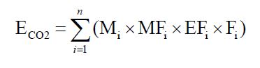
Where:
- ECO2
- Process emissions of CO2 from the furnace (tonnes).
- n
- Number of carbonate-based raw materials charged to furnace.
- MFi
- Annual average mass fraction of carbonate-based mineral i in carbonate-based raw material i (weight fraction).
- Mi
- Annual amount of carbonate-based raw material i charged to furnace (tonnes).
- EFi
- Emission factor for carbonate-based mineral i (tonnes CO2 per tonne carbonate-based mineral as shown in Table 140-1.
- Fi
- Fraction of calcination achieved for carbonate-based mineral i, 1.0 for completed calcination(weight fraction).
The person shall calculate and report the total process CO2 emissions from glass melting furnaces at the facility using Equation 140-2 of this section:
Equation 140-2:
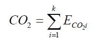
Where:
- CO2
- Annual process CO2 emissions from glass manufacturing facility (tonnes).
- ECO2i
- Annual CO2 emissions from glass melting furnace i (tonnes).
- k
- Number of glass melting furnaces.
- Calculate and report under ON.20 the combustion CO2 emissions in the glass furnace according to the applicable requirements in ON.20.
ON.144 Sampling, Analysis, and Measurement Requirements
- The person shall measure annual amounts of carbonate-based raw materials charged to each glass melting furnace from monthly measurements using plant instruments used for accounting purposes, such as calibrated scales or weigh hoppers. Total annual mass charged to glass melting furnaces at the facility shall be compared to records of raw material purchases for the year.
- The person shall measure carbonate-based mineral mass fractions at least annually to verify the mass fraction data provided by the supplier of the raw material; such measurements shall be based on sampling and chemical analysis conducted by a laboratory using ASTM D3682 or any of the other analytical methods listed in the Technical Reference Document section of this Guideline (section 5), or the most appropriate method published by a consensus-based standards organization. If no appropriate method is published by a consensus-based standards organization, use industry standard methods, noting where such methods are used and what methods are used.
- The person shall determine the annual average mass fraction for the carbonate-based mineral in each carbonate-based raw material by calculating an arithmetic average of the monthly data obtained from raw material suppliers or sampling and chemical analysis.
- As an alternative to data provided by the raw material supplier, a value of 1.0 can be used for the monthly mass fraction (MFi) of carbonate-based mineral i in Equation 140-1 of this section.
- The person shall determine on an annual basis the calcination fraction for each carbonate consumed based on sampling and chemical analysis using an industry consensus standard, or use a value of 1.0 for the calcination fraction. This chemical analysis shall be conducted using an x-ray fluorescence test or other enhanced testing method published by an industry consensus-based standards organization. If no appropriate method is published by a consensus-based standards organization, use industry standard methods, noting where such methods are used and what methods are used.
- The person shall measure the quantity of glass production. Equipment used to measure the production quantity shall be:
- calibrated according to the manufacturer’s instructions and
- maintained to achieve an accuracy of plus or minus 5%.
ON.145 Procedures for Estimating Missing Data
Unavailable analytical Data
- Whenever analytical data relating to sampling is unavailable, the person shall, using the methods prescribed in ON.144, re-analyze the original sample, a backup sample or a replacement sample for the same measurement and sampling period.
Determination of quantity
- Whenever sampling and measurement data required by ON.144 for the calculation of emissions is missing the person shall ensure that the data is replaced using the following missing data procedures:
- When the missing data concerns carbon content, temperature, pressure or gas concentration, the person shall,
Determine the sampling or measurement rate using the following Equation 140-3:
Equation 140-3:
R = QSAct ⁄ QSRequiredWhere:
- When the missing data concerns carbon content, temperature, pressure or gas concentration, the person shall,
- R
- Sampling or measurement rate that was used, expressed as a percentage
- QSAct
- Quantity of actual samples or measurements obtained by the person
- QSRequired
- Quantity of samples or measurements required under ON.144
- Replace the missing data as follows,
- If R ≥ 0.9: replace the missing data by the arithmetic mean of the sampling or measurement data from immediately before and after the missing data period. If no data is available from before the missing data period, the person shall use the first available data from after the missing data period;
- If 0.75 ≤ R < 0.9: replace the missing data by the highest data value sampled or analyzed during the reporting period for which the calculation is made;
- If R < 0.75: replace the missing data by the highest data value sampled or analyzed during the 3 preceding years;
- When the missing data concerns raw material consumption, glass production or carbonate consumption, the replacement data shall be generated from best estimates based on all of the data relating to the processes.
- For all units subject to the requirements of ON.20 that monitor and report emissions using a CEMS, the missing data backfilling procedures in EPS 1/PG/7 shall be followed for CO2 concentration, stack gas flow rate, fuel flow rate, high heating value, and fuel carbon content.
| Carbonate-Based Raw Material – Mineral | CO2 Emission Factora |
|---|---|
| Limestone – CaCO3 | 0.43971 |
| Dolomite – CaMg(CO3)2 | 0.47732 |
| Sodium carbonate/soda ash – Na2CO3 | 0.41492 |
a Emission factors in units of tonnes of CO2 emitted per tonne of carbonate-based mineral charged to the furnace.
ON.120 HCFC-22 Production and HFC-23 Destruction
ON.121 Activity Definition
For the purposes of this standard quantification method:
- HCFC-22 production and HFC-23 destruction
- has the same meaning as in the Regulation.
- Person
- means a person that engages in HCFC-22 Production or HFC-23 destruction.
ON.122 Greenhouse Gas Reporting Requirements
A person shall set out the following information, calculated for the calendar year using standard quantification methods ON.120 – ON.125, in an emission report prepared for a calendar year in respect of HCFC-22 production and HFC-23 destruction at a facility:
- HFC-23 emissions from HCFC-22 production processes and HFC-23 destruction processes.
ON.123 Calculation of GHG Emissions
Quantify emissions in accordance with US EPA 40 CFR 98 Subpart O Section 98.153.
ON.124 Sampling, Analysis, and Measurement Requirements
Sampling, analysis and measurement requirements for this activity shall be done in accordance with US EPA 40 CFR 98 Subpart O Section 98.154.
ON.125 Procedures for Estimating Missing Data
Missing data requirements for this activity shall be estimated in accordance with US EPA 40 CFR 98 Subpart O Section 98.155.
ON.130 Hydrogen Production
ON.131 Activity Definition
For the purposes of this standard quantification method:
- Hydrogen production
- has the same meaning as in the Regulation.
- Person
- means a person that engages in hydrogen production.
ON.132 Greenhouse Gas Reporting Requirements
A person shall set out the following information, calculated for the calendar year using standard quantification methods ON.130 – ON.135, in an emission report prepared for a calendar year in respect of hydrogen production at a facility:
- Process CO2 Emissions. The CO2 process emissions from the hydrogen production process (tonnes).
- Feedstock Consumption (if estimating emissions using mass balance approach in ON.133(b)). Annual feedstock consumption by feedstock type (including petroleum coke) reported in units of million standard cubic metres for gases, kilolitres for liquids, tonnes for non-biomass solids, and bone dry tonnes for biomass-derived solid fuels.
- Production. Annual hydrogen produced (tonnes), excluding any molecular hydrogen that is in the feedstock used in a steam methane reformer.
ON.133 Calculation of Greenhouse Gas Emissions
The person shall calculate and report CO2 process emissions using the methods in paragraphs (a) or (b) of this section.
- Continuous Emission Monitoring Systems. The person may calculate CO2 process emissions using CEMS. The person shall comply with the requirements in section ON.20.
- Feedstock Material Balance. The person may calculate CO2 process emissions using the following method.
Gaseous fuel and feedstock. The person shall calculate the annual CO2 process emissions from gaseous fuel and feedstock according to Equation 130-1 of this section:
Equation 130-1:
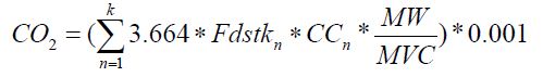
Where:
- CO2
- Annual CO2 process emissions arising from fuel and feedstock consumption (tonnes/year).
- Fdstkn
- Volume of the gaseous fuel and feedstock used in month n at reference temperature and pressure conditions (Rm3). If a mass flow meter is used, measure the gaseous product produced in month “n” in kg and replace the term “MW⁄MVC” with “1”.
- CCn
- Weighted average carbon content of the gaseous fuel and feedstock, from the results of one or more analyses for month n (Rm3 at reference temperature and pressure conditions as used by the facility). If a mass flow meter is used, measure the feedstock used in month n in kg and replace the term “MW⁄MVC” with “1”.
- MW
- Molecular weight of the gaseous fuel and feedstock (kg/kg-mole).
- MVC
- Molar volume conversion factor at the same reference conditions as the above Fdstkn (Rm3/kg-mole). MVC can be
- 8.3145 × [273.16 + reference temperature in °C] ⁄ [reference pressure in kilopascal].
- k
- Months in the year.
- 3.664
- Ratio of molecular weights, CO2 to carbon.
- 0.001
- Conversion factor from kg to tonnes.
Liquid fuel and feedstock. The person shall calculate the annual CO2 process emissions from liquid fuel and feedstock according to Equation 130-2 of this section:
Equation 130-2:
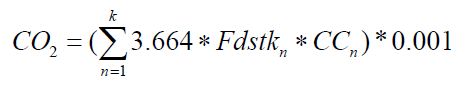
Where:
- CO2
- Annual CO2 emissions arising from fuel and feedstock consumption (tonnes/year).
- Fdstkn
- Volume of the liquid fuel and feedstock used in month n (m3 of fuel and feedstock). If a mass flow meter is used, measure the fuel and feedstock used in month n in kg and measure the carbon content of feedstock in kg C per kg of feedstock.
- CCn
- Weighted average carbon content of the liquid fuel and feedstock, from the results of daily analyses for month n (kg of C per m3 of fuel and feedstock when the usage is measured in m3, or kg of C per kg of feedstock and fuel when the usage is measured in kg).
- k
- Months in the year.
- 3.664
- Ratio of molecular weights, CO2 to carbon.
- 0.001
- Conversion factor from kg to tonnes.
Solid fuel and feedstock. The person shall calculate the annual CO2 process emissions from solid fuel and feedstock according to Equation 130-3 of this section:
Equation 130-3:
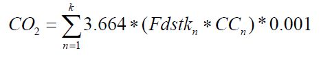
Where:
- CO2
- Annual CO2 emissions from fuel and feedstock consumption in tonnes per year month (tonnes/year).
- Fdstkn
- Mass of solid fuel and feedstock used in month n (kg of fuel and feedstock).
- CCn
- Weighted average carbon content of the solid fuel and feedstock, from the results of daily analyses for month n (kg carbon per kg of fuel and feedstock).
- k
- Months in the year.
- 3.664
- Ratio of molecular weights, CO2 to carbon.
- 0.001
- Conversion factor from kg to tonnes.
- If GHG emissions from a hydrogen production process unit are vented through the same stack as any combustion unit or process equipment that reports CO2 emissions using a CEMS that complies with ON.23, then the calculation methodology in paragraph (b) of this section shall not be used to calculate process emissions. The person shall report the combined stack emissions according to the CEMS methodology in ON.23.
ON.134 Sampling, Analysis, and Measurement Requirements
- Persons using CEMS to estimate CO2 emissions shall comply with the monitoring requirements in Calculation Methodology 4 of ON.23.
- Persons using the methods in section ON.133 (b) or paragraph (c) of this section shall perform the following monitoring:
- The person shall measure the feedstock consumption rate daily.
- The person shall collect samples of each feedstock consumed and analyze each sample for carbon content using the methods specified in paragraph (c) of this section. For natural gas feedstock not mixed with another feedstock prior to consumption, samples shall be collected and analyzed once per month. For all other feedstocks, samples shall be collected and analyzed daily and a weighted average established for month n. Daily samples may be combined to generate a monthly composite sample for carbon analysis. The samples shall be collected from a location in the feedstock handling system that provides samples representative of the feedstock consumed in the hydrogen production process.
- Persons shall quantify the hydrogen produced daily. Equipment used to measure the production quantity shall be:
- calibrated according to the manufacturer’s instructions and
- maintained to achieve an accuracy of plus or minus 5%.
- The calibration requirements under paragraph (c) do not apply to meters that are used for financial transactions if the supplier and purchaser do not have common owners and are not owned by subsidiaries or affiliates of the same company.
- Persons shall quantify the CO2 and CO collected and transferred off-site quarterly.
- The person shall use the following methods, as applicable, to determine the carbon content of the feedstocks:
- Any of the applicable analytical methods listed in the Technical Reference Document section of this Guideline (section 5).
- The most appropriate method published by a consensus-based standards organization to determine the carbon content of the feedstocks. If no appropriate method is published by a consensus-based standards organization, use industry standard methods, noting where such methods are used and what methods are used.
ON.135 Procedures for Estimating Missing Data
Unavailable analytical Data
- Whenever analytical data relating to sampling is unavailable, the person shall, using the methods prescribed in ON.134, re-analyze the original sample, a backup sample or a replacement sample for the same measurement and sampling period.
Determination of quantity
- Whenever sampling and measurement data required by ON.134 for the calculation of emissions is missing the person shall ensure that the data is replaced using the following missing data procedures:
- When the missing data concerns carbon content, temperature, pressure or gas concentration, the person shall:
Determine the sampling or measurement rate using the following Equation 130-4:
Equation 130-4:
R = QSAct ⁄ QSRequired
Where:
- When the missing data concerns carbon content, temperature, pressure or gas concentration, the person shall:
- R
- Sampling or measurement rate that was used, expressed as a percentage
- QSAct
- Quantity of actual samples or measurements obtained by the person
- QSRequired
- Quantity of samples or measurements required under ON.134
- Replace the missing data as follows,
- If R ≥ 0.9: replace the missing data by the arithmetic mean of the sampling or measurement data from immediately before and after the missing data period. If no data is available from before the missing data period, the person shall use the first available data from after the missing data period;
- If 0.75 ≤ R < 0.9: replace the missing data by the highest data value sampled or analyzed during the reporting period for which the calculation is made;
- If R < 0.75: replace the missing data by the highest data value sampled or analyzed during the 3 preceding years;
- When the missing data concerns raw material consumption or hydrogen production, the replacement data shall be generated from best estimates based on all of the data relating to the processes.
- For all units subject to the requirements of ON.20 that monitor and report emissions using a CEMS, the missing data backfilling procedures in EPS 1/PG/7 shall be followed for CO2 concentration, stack gas flow rate, fuel flow rate, high heating value, and fuel carbon content.
ON.150 Iron and Steel Production
ON.151 Activity Definition
For the purposes of this standard quantification method:
- Iron and steel production
- has the same meaning as in the Regulation.
- Person
- means a person that engages in iron and steel production.
ON.152 Greenhouse Gas Reporting Requirements
A person shall set out the following information, calculated for the calendar year using standard quantification methods ON.150 – ON.155, in an emission report prepared for a calendar year in respect of iron and steel production at a facility:
- Annual process CO2 emissions (tonnes) for the following processes:
- Taconite indurating furnace
- Basic oxygen furnace (BOF)
- Coke making operation
- Sinter process
- Electric arc furnace (EAF)
- Argon-oxygen decarburization vessel
- Direct reduction furnace
- Blast furnace
- Annual production/usage quantities (tonnes) for the following processes:
- Taconite indurating furnace - fired pellets produced on-site
- BOF steel produced on-site
- Coke making operation - coke produced and coal charged
- Sinter process - sinter produced
- EAF steel produced on-site
- Argon-oxygen decarburization vessel - molten steel charged
- Direct reduction furnace - iron produced
- Liquid iron produced in the blast furnace.
- Limestone used in the blast furnace
- Dolomite used in the blast furnace
- CO2, N2O, and CH4 emissions, not accounted for elsewhere in ON.150, from stationary combustion units using the methods specified in ON.20 (tonnes). Report these emissions from stationary combustion for each of the following devices:
- Taconite indurating furnace
- BOF
- Coke oven batteries
- Sintering furnace
- EAF
- Argon-oxygen decarburization vessel
- Direct reduction furnace
- Blast furnace
- Any other stoves, boiler, process heaters, reheat furnaces and other combustion sources.
ON.153 Calculation of CO2 Emissions
- Process CO2 emissions. Determine process CO2 emissions as specified under either paragraph (1) or (2) of this section.
- Continuous emissions monitoring systems (CEMS) as specified in Calculation Methodology 4 of ON.23.
- Calculation methodologies specified in paragraph (b) of this section.
- Process CO2 Emissions Calculation Methodology. Calculate CO2 process emissions for each taconite indurating furnace, basic oxygen furnace, non-recovery coke oven battery, sinter process, EAF, argon-oxygen decarburization vessel, blast furnace, and direct reduction furnace using the following mass balance approaches specified in paragraphs (b)(1) through (b)(8). Specific process inputs or outputs that contribute less than 1 per cent of the total mass of carbon into or out of the process do not have to be included in the paragraphs (b)(1) through (b)(8) mass balances.
Calculate taconite indurating furnace CO2 emissions using Equation 150-1:
Equation 150-1:
ET = [(T × CT) − (P × CP) − (R × CR)] × 3.664
Where:
- ET
- Annual CO2 emissions from taconite indurating furnace (tonnes);
- T
- Annual mass of greenball (taconite) pellets fed to furnace (tonnes);
- CT
- Carbon content of greenball (taconite) pellets (tonnes C/tonnes taconite pellets);
- P
- Annual mass of fired pellets produced by the furnace (tonnes);
- CP
- Carbon content of fired pellets (tonnes C/tonnes fired pellets);
- R
- Annual mass of air pollution control residue collected (tonnes);
- CR
- Carbon content of air pollution control residue (tonnes C/tonnes residue);
- 3.664
- Conversion factor from tonnes of C to tonnes of CO2.
Calculate basic oxygen process furnace CO2 emissions using Equation 150-2:
Equation 150-2:
EBOF = [(I × CI) + (SC × CSC) + (FL × CFL) + (CAR × CCAR) − (ST × CST) − (SL × CSL) − (BOG × CBOG) − (R × CR)] × 3.664
Where:
- EBOF
- Annual CO2 emissions from basic oxygen furnaces (tonnes);
- I
- Annual mass of molten iron charged to furnace (tonnes);
- CI
- Carbon content of molten iron (tonnes C/tonnes molten iron);
- SC
- Annual mass of ferrous scrap charged to furnace (tonnes);
- CSC
- Carbon content of ferrous scrap (tonnes C/tonnes ferrous scrap);
- FL
- Annual mass for flux materials (e.g., limestone, dolomite, etc.) charged to furnace (tonnes);
- CFL
- Carbon content of non-biomass flux materials (tonnes C/tonnes flux material);
- CAR
- Annual mass of carbonaceous material (e.g., coal, coke, etc.) charged to furnace (tonnes);
- CCAR
- Carbon content of non-biomass carbonaceous material (tonnes C/tonnes carbonaceous material);
- ST
- Annual mass of molten raw steel produced by furnace (tonnes);
- CST
- Carbon content of steel (tonnes C/tonnes steel);
- SL
- Annual mass of slag produced by furnace (tonnes);
- CSL
- Carbon content of slag (tonnes C/tonnes slag);
- BOG
- Annual mass of basic oxygen furnace gas transferred off site (tonnes);
- CBOG
- Carbon content of non-biomass basic oxygen furnace gas transferred off site (tonnes C/tonnes basic oxygen furnace gas);
- R
- Annual mass of air pollution control residue collected (tonnes);
- CR
- Carbon content of air pollution control residue (tonnes C/tonnes residue);
Calculate coke oven battery CO2 emissions using Equation 150-3:
Equation 150-3:
Ecoke = [(CC × CCC) − (CO × CCO) − (BY × CBY) − (R × CR) − (COG × CCOG)] × 3.664
Where:
- Ecoke
- Annual CO2 emissions from coke production (tonnes);
- CC
- Annual mass of coking coal and nonfuel carbonaceous material charged to battery (tonnes);
- CCC
- Non-biomass carbon content of coking coal and nonfuel carbonaceous material (tonnes C/tonnes coking coal and nonfuel carbonaceous material);
- CO
- Annual mass of coke produced (tonnes);
- CCO
- Carbon content of coke (tonnes C/tonnes coke);
- BY
- Annual mass of by-product from by-product coke oven battery (tonnes);
- CBY
- Non-biomass carbon content of by-product (tonnes C/tonnes by-product);
- R
- Quantity of air pollution control residue collected (tonnes);
- CR
- Carbon content of air pollution control residue (tonnes C/tonnes residue);
- COG
- Annual mass of coke oven gas transferred off site (tonnes);
- CCOG
- Non-biomass carbon content of coke oven gas transferred off site (tonnes C/tonnes coke oven gas);
- 3.664
- Conversion factor from tonnes of C to tonnes of CO2.
Calculate sinter process CO2 emissions using Equation 150-4:
Equation 150-4:
Esinter = [(CAR × CCAR) + (FE × CFE) − (S × CS) − (R × CR)] × 3.664
Where:
- Esinter
- Annual CO2 emissions from sinter process (tonnes);
- CAR
- Annual mass of carbonaceous material (e.g., coal, coke, etc.) charged to furnace (tonnes);
- CCAR
- Carbon content of non-biomass carbonaceous material (tonnes C/tonnes carbonaceous material);
- FE
- Annual mass of sinter feed material (tonnes);
- CFE
- Carbon content of sinter feed material (tonnes C/tonnes sinter feed material);
- S
- Annual mass of sinter produced (tonnes);
- CS
- Carbon content of sinter produced (tonnes C/tonnes sinter);
- R
- Quantity of air pollution control residue collected (tonnes);
- CR
- Carbon content of air pollution control residue (tonnes C/tonnes residue);
- 3.664
- Conversion factor from tonnes of C to tonnes of CO2.
Calculate electric arc furnace (EAF) CO2 emissions using Equation 150-5:
Equation 150-5:
EEAF = [(I × CI) + (SC × CSC) + (FL × CFL) + (EL × CEL) + (CAR × CCAR) − (ST × CST) − (SL × CSL) − (R × CR)] × 3.664
Where:
- EEAF
- Annual CO2 emissions from EAF (tonnes);
- I
- Annual mass of direct reduced iron (if any) charged to furnace (tonnes);
- CI
- Carbon content of direct reduced iron (tonnes C/tonnes direct reduced iron);
- SC
- Annual mass of ferrous scrap charged to furnace (tonnes);
- CSC
- Carbon content of ferrous scrap (tonnes C/tonnes ferrous scrap);
- FL
- Annual mass for flux materials (e.g., limestone, dolomite, etc.) charged to furnace (tonnes);
- CFL
- Carbon content of non-biomass flux materials (tonnes C/tonnes flux material);
- EL
- Annual mass for carbon electrodes consumed (tonnes);
- CEL
- Carbon content of non-biomass carbon electrodes (tonnes C/tonnes carbon electrode);
- CAR
- Annual mass of carbonaceous material (e.g., coal, coke, etc.) charged to furnace (tonnes);
- CCAR
- Non-biomass carbon content of carbonaceous material (tonnes C/tonnes carbonaceous material);
- ST
- Annual mass of molten raw steel produced by furnace (tonnes);
- CST
- Carbon content of steel (tonnes C/tonnes steel);
- SL
- Annual mass of slag produced by furnace (tonnes);
- CSL
- Carbon content of slag (tonnes C/tonnes slag);
- R
- Annual mass of air pollution control residue collected (tonnes);
- CR
- Carbon content of air pollution control residue (tonnes C/tonnes residue);
- 3.664
- Conversion factor from tonnes of C to tonnes of CO2.
Calculate argon-oxygen decarburization vessel CO2 emissions using Equation 150-6:
Equation 150-6:
EAOD = [Steel × (Cin − Cout) − (R × CR)] × 3.664
Where:
- EAOD
- Annual CO2 emissions from argon-oxygen decarburization vessels (tonnes);
- Steel
- Annual mass of molten steel charged to vessel (tonnes);
- Cin
- Carbon content of molten steel before decarburization (tonnes C/tonnes molten steel);
- Cout
- Carbon content of molten steel after decarburization (tonnes C/tonnes molten steel);
- R
- Annual mass of air pollution control residue collected (tonnes);
- CR
- Carbon content of air pollution control residue (tonnes C/tonnes residue);
- 3.664
- Conversion factor from tonnes of C to tonnes of CO2.
Calculate direct reduction furnace CO2 emissions using Equation 150-7:
Equation 150-7:
EDR = [(Ore × COre) + ∑(CAR × CCAR) + ∑(OT × COT) − (I × CI) − (NM × CNM) − (R × CR)] × 3.664
Where:
- EDR
- Annual CO2 emissions from direct reduction furnace (tonnes);
- Ore
- Annual mass of iron ore or iron ore pellets fed to the furnace (tonnes);
- COre
- Carbon content of iron ore or iron ore pellets (tonnes C/tonnes iron ore or iron ore pellets);
- CAR
- Annual mass of non-fuel carbonaceous materials (e.g., coal, coke, by-products, etc.) charged to furnace (tonnes);
- CCAR
- non-biomass carbon content of non-fuel carbonaceous materials (tonnes C/tonnes non-fuel carbonaceous material);
- OT
- Annual mass of other materials charged to furnace (tonnes);
- COT
- non-biomass carbon content of other materials (tonnes C/tonnes other materials);
- I
- Annual mass of iron produced (tonnes);
- CI
- Carbon content of iron (tonnes C/tonnes iron);
- NM
- Annual mass for non-metallic materials produced (tonnes);
- CNM
- Carbon content of non-metallic materials (tonnes C/tonnes non-metallic minerals);
- R
- Annual mass of air pollution control residue collected (tonnes);
- CR
- Carbon content of air pollution control residue (tonnes C/tonnes residue);
- 3.664
- Conversion factor from tonnes of C to tonnes of CO2.
Calculate blast furnace CO2 emissions using Equation 150-8:
Equation 150-8:
EBF = [(Ore × COre) + ∑(CAR × CCAR) + ∑(F × CF) + ∑(OT × COT) − (I × CI) − (NM × CNM) − (BG × CBG) − (R × CR)] × 3.664
Where:
- EBF
- Annual CO2 emissions from blast furnace (tonnes);
- Ore
- Annual mass of iron ore or iron ore pellets fed to the furnace (tonnes);
- COre
- Carbon content of iron ore or iron ore pellets (tonnes C/tonnes iron ore or iron ore pellets);
- CAR
- Annual mass of non-fuel carbonaceous materials (e.g., coal, coke, by-products, etc.) charged to furnace (tonnes);
- CCAR
- Non-biomass carbon content of non-fuel carbonaceous materials (tonnes C/tonnes non-fuel carbonaceous material);
- F
- Annual mass for flux materials (e.g., limestone, dolomite, etc.) charged to furnace (tonnes);
- CF
- Non-biomass carbon content of flux materials (tonnes C/tonnes flux material);
- OT
- Annual mass of other materials charged to furnace (tonnes);
- COT
- Non-biomass carbon content of other materials (tonnes C/tonnes other materials);
- I
- Annual mass of iron produced (tonnes);
- CI
- Carbon content of iron (tonnes C/tonnes iron);
- NM
- Annual mass for non-metallic materials produced (tonnes);
- CNM
- Carbon content of non-metallic materials (tonnes C/tonnes non-metallic minerals);
- BG
- Annual mass for blast furnace gas transferred off-site (tonnes);
- CBG
- Non-biomass carbon content of blast furnace gas (tonnes C/tonnes blast furnace gas);
- R
- Annual mass of air pollution control residue collected (tonnes);
- CR
- Carbon content of air pollution control residue (tonnes C/tonnes residue);
- 3.664
- Conversion factor from tonnes of C to tonnes of CO2.
Calculate total CO2 emissions using Equation 150-9:
Equation 150-9:
ECO2 = ET + EBOF + Ecoke + Esinter + EEAF + EAOD + EDR + EBF
Where:
- ECO2
- Total CO2 emissions (tonnes);
- ET
- Emissions from taconite indurating furnace (tonnes);
- EBOF
- Emissions from basic oxygen furnace (BOF) (tonnes);
- Ecoke
- Emissions from coke production (tonnes);
- Esinter
- Emissions from sinter production (tonnes);
- EEAF
- Emissions from electric arc furnace (EAF) (tonnes);
- EAOD
- Emissions from argon-oxygen decarburization vessels (tonnes);
- EDR
- Emissions from direct reduction furnace (tonnes);
- EBF
- Emissions from blast furnace (tonnes);
- Calculate CO2, N2O, and CH4 emissions, not accounted for elsewhere in ON.150, from stationary combustion units using the methods specified in ON.23 and ON.24 for each of the processes identified in ON.152(c).
ON.154 Sampling, Analysis, and Measurement Requirements
The annual mass of each material used in the ON.153 mass balance methodologies shall be determined using plant instruments used for accounting purposes, including either direct measurement of the quantity of material used in the process or by calculations using process operating information.
The average carbon content of each material used shall be determined as specified under paragraph (a) or (b) of this section.
- Obtain carbon content by collecting and analyzing at least three representative samples of the material each year using one of the following methods:
- For iron ore, taconite pellets, and other iron-bearing materials, use ASTM E1915.
- For iron and ferrous scrap, use ASTM E1019.
- For coal, coke, and other carbonaceous materials (e.g., electrodes, etc.), use ASTM D5373 or ASTM D5142.
- For petroleum liquid based fuels and liquid waste-derived fuels, use ASTM D5291 and either ASTM D2502 or ASTM D2503.
- For steel, use one of the methods described in subparagraph (i) through (iv):
- ASM CS-104 UNS No. G10460.
- ISO/TR 15349-1: 1998.
- ISO/TR 15349-3: 1998.
- ASTM E415.
- ASTM E1019.
- For flux (i.e., limestone or dolomite) and slag, use ASTM C25.
- For fuels, determine carbon content and molecular weight (if applicable) using the applicable methods listed in ON.20.
- For steel production by-products (e.g., blast furnace gas, coke oven gas, coal tar, light oil, sinter off gas, slag dust, etc.); use an online instrument that determines carbon content to ±5%; or use sampling and analysis listed in ON.25; or any of the other analytical methods listed in this subsection or Technical Reference Document section of this Guideline (section 5); or methodologies using plant instruments used for accounting purposes.
- If a person is unable to use the methods listed in (1) – (8) above, the person shall use
- Any of the other analytical methods listed in the Technical Reference Document section of this Guideline (section 5). or
- The most appropriate method published by a consensus-based standards organization. If no appropriate method is published by a consensus-based standards organization, use industry standard methods, noting where such methods are used and what methods are used.
- Obtain carbon content from material vendor or supplier.
- The person shall measure the quantity ofproduction and material usage required to be reported in ON.152(b).
- Equipment used to measure the production quantity and material usage under ON.152(b) shall be:
- calibrated according to the manufacturer’s instructions where available; or, where not available calibrated according to practices used for accounting purposes;
- maintained to achieve an accuracy of plus or minus 5%.
- The person may use engineering estimates, mass balance along with measurements to determine the amount of coke produced.
- Equipment used to measure the production quantity and material usage under ON.152(b) shall be:
ON.155 Procedures for Estimating Missing Data
Unavailable analytical Data
- Whenever analytical data relating to sampling is unavailable, the person shall, using the methods prescribed in ON.154, re-analyze the original sample, a backup sample or a replacement sample for the same measurement and sampling period.
Determination of quantity
- Whenever sampling and measurement data required by ON.154 for the calculation of emissions is missing the person shall ensure that the data is replaced using the following missing data procedures:
- When the missing data concerns carbon content, temperature, pressure or gas concentration, the person shall:
Determine the sampling or measurement rate using the following Equation 150-10:
Equation 150-10:
R = QSAct ⁄ QSRequired
Where:
- When the missing data concerns carbon content, temperature, pressure or gas concentration, the person shall:
- R
- Sampling or measurement rate that was used, expressed as a percentage
- QSAct
- Quantity of actual samples or measurements obtained by the person
- QSRequired
- Quantity of samples or measurements required under ON.154
- Replace the missing data as follows,
- If R ≥ 0.9: replace the missing data by the arithmetic mean of the sampling or measurement data from immediately before and after the missing data period. If no data is available from before the missing data period, the person shall use the first available data from after the missing data period;
- If 0.75 ≤ R < 0.9: replace the missing data by the highest data value sampled or analyzed during the reporting period for which the calculation is made;
- If R < 0.75: replace the missing data by the highest data value sampled or analyzed during the 3 preceding years;
- When the missing data concerns the consumption of carbon-containing raw material, consumption of ferrous scrap, annual consumption of molten iron, consumption of coking coal, consumption of flux material, consumption of direct reduced iron pellets, consumption of carbon electrodes, consumption of ore, quantity of slag produced, consumption of greenball pellets, production of fired pellets, production of coke oven gas, production of metallurgical coke, quantity of air pollution control residue collected, quantity of other coke oven by-products, the quantity of steel processed or produced, quantity of gas from basic oxygen furnaces transferred, the production of sinter, the production of iron or the quantity of non-metallic by-products, the replacement data shall be generated from best estimates based on all of the data relating to the processes.
- For all units subject to the requirements of ON.20 that monitor and report emissions using a CEMS, the missing data backfilling procedures in EPS 1/PG/7 shall be followed for CO2 concentration, stack gas flow rate, fuel flow rate, high heating value, and fuel carbon content.
ON.160 Lead production
ON.161 Activity Definition
For the purposes of this standard quantification method:
- Lead production
- has the same meaning as in the Regulation.
- Person
- means a person that engages in lead production.
ON.162 Greenhouse Gas Reporting Requirements
A person shall set out the following information, calculated for the calendar year using standard quantification methods ON.160 – ON.165, in an emission report prepared for a calendar year in respect of lead production at a facility:
- Annual emissions of CO2 at the facility level (tonnes).
- Annual quantities of each carbon-containing input material used (tonnes).
- Carbon content of each carbon-containing input material used (tonnes C/tonne input material.
- Inferred waste-based carbon-containing material emission factor (if waste-based reducing agent quantification method used)
- Annual lead production (tonnes)
ON.163 Calculation of CO2 Emissions
Calculate total CO2 emissions as specified under paragraph (a) or (b) of this section.
- Determine facility CO2 emissions using continuous emissions monitoring systems (CEMS) as specified in Calculation Methodology 4 of ON.23.
Calculate total CO2 emissions using Equation 160-1. Specific materials that contribute less than 1 per cent of the total carbon into the process do not have to be included in the calculation using Equation 160-1.
Equation 160-1:
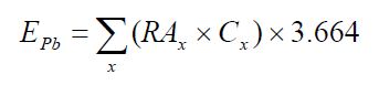
Where:
- EPb
- Annual CO2 emissions from lead production (tonnes);
- RAx
- Annual quantity of material x used (tonnes);
- Cx
- Carbon content of material x (tonnes C/tonnes of x);
- 3.664
- Conversion factor from tonnes of C to tonnes of CO2.
ON.164 Sampling, Analysis, and Measurement Requirements
The annual mass of each material introduced into the smelting furnace shall be determined using plant instruments used for accounting purposes, including either direct measurement of the quantity of the material placed in the unit or by calculations using process operating information.
The average carbon content of each material introduced into the smelting furnace shall be determined as specified under paragraph (a), (b), or (c) of this section.
- Obtain carbon content by collecting and analyzing at least three representative samples of the material each year using one of the following methods:
- For solid carbonaceous reducing agents and carbon electrodes, use ASTM D5373.
- For liquid reducing agents, use one of the methods described in subparagraph (i) through (iv):
- ASTM D2502.
- ASTM D2503.
- ASTM D3238.
- ASTM D5291.
- For gaseous reducing agents, use one of the methods described in subparagraph (i) or (ii):
- ASTM D1945.
- ASTM D1946.
- For waste-based carbon-containing material, determine carbon content by:
- Operating the smelting furnace both with and without the waste-reducing agents while keeping the composition of other material introduced constant; or
- Using engineering estimates to derive the carbon content of the waste-based carbon containing material.
- Obtain carbon content from material vendor or supplier.
- The person shall measure the lead production quantity. Equipment used to measure the production quantity shall be:
- calibrated according to the manufacturer’s instructions and
- maintained to achieve an accuracy of plus or minus 5%.
ON.165 Procedures for Estimating Missing Data
Unavailable analytical Data
- Whenever analytical data relating to sampling is unavailable, the person shall, using the methods prescribed in ON.164, re-analyze the original sample, a backup sample or a replacement sample for the same measurement and sampling period.
Determination of quantity
- Whenever sampling and measurement data required by ON.164 for the calculation of emissions is missing the person shall ensure that the data is replaced using the following missing data procedures:
- When the missing data concerns carbon content, temperature, pressure or gas concentration, the person shall:
Determine the sampling or measurement rate using the following Equation 160-2:
Equation 160-2:
R = QS Act ⁄ QS Required
Where:
- When the missing data concerns carbon content, temperature, pressure or gas concentration, the person shall:
- R
- Sampling or measurement rate that was used, expressed as a percentage
- QSAct
- Quantity of actual samples or measurements obtained by the person
- QSRequired
- Quantity of samples or measurements required under ON.164
- Replace the missing data as follows,
- If R ≥ 0.9: replace the missing data by the arithmetic mean of the sampling or measurement data from immediately before and after the missing data period. If no data is available from before the missing data period, the person shall use the first available data from after the missing data period;
- If 0.75 ≤ R < 0.9: replace the missing data by the highest data value sampled or analyzed during the reporting period for which the calculation is made;
- If R < 0.75: replace the missing data by the highest data value sampled or analyzed during the 3 preceding years;
- When the missing data concerns the consumption of carbon-containing raw material, consumption of ferrous scrap, annual consumption of molten iron, consumption of coking coal, consumption of flux material, consumption of direct reduced iron pellets, consumption of carbon electrodes, consumption of ore, quantity of slag produced, consumption of greenball pellets, production of fired pellets, production of coke oven gas, production of metallurgical coke, quantity of air pollution control residue collected, quantity of other coke oven by-products, the quantity of steel processed or produced, quantity of gas from basic oxygen furnaces transferred, the production of sinter, the production of iron or the quantity of non-metallic by-products, the replacement data shall be generated from best estimates based on all of the data relating to the processes.
- For all units subject to the requirements of ON.20 that monitor and report emissions using a CEMS, the missing data backfilling procedures in EPS 1/PG/7 shall be followed for CO2 concentration, stack gas flow rate, fuel flow rate, high heating value, and fuel carbon content.
ON.170 Lime Production
ON.171 Activity Definition
For the purposes of this standard quantification method:
- Lime production
- has the same meaning as in the Regulation.
- Person
- means a person that engages in lime production.
ON.172 Greenhouse Gas Reporting Requirements
A person shall set out the following information, calculated for the calendar year using standard quantification methods ON.170 – ON.175, in an emission report prepared for a calendar year in respect of lime production at a facility:
- CO2 process emission from lime production for all kilns (excluding emissions from fuel combustion) in tonnes.
- CO2 process emissions from lime production (tonnes) for all kilns combined and the following information if the process CO2 emissions are calculated according to the procedures specified in ON.173(b):
- For lime production:
- The emission factor (tonne CO2/tonne) for each lime type for each month.
- The quantity of each type of lime produced (tonnes) each month.
- The calcium oxide (CaO) content (weight fraction) of each lime type for each month.
- The magnesium oxide (MgO) content (weight fraction) of each lime type for each month.
- For the production of calcined byproducts and wastes:
- The emission factor (tonne CO2/tonne) for each calcined byproduct/waste type for each quarter.
- The quantity of each type of calcined byproduct/waste type produced each quarter.
- The calcium oxide (CaO) content (weight fraction) of each calcined byproduct/waste type for each quarter.
- The magnesium oxide (MgO) content (weight fraction) of each calcined byproduct/waste type for each quarter.
- For lime production:
- CO2, CH4, and N2O emissions from fuel combustion in all kilns combined, following the calculation methodologies and reporting requirements specified in ON.173(c) (tonnes).
- The annual quantity of each type of lime produced (tonnes).
- The annual emissions from the production of iron coated lime.
- CO2, CH4 and N2O emissions from fuel combustion from the production of iron coated lime.
- Process CO2 emissions from the production of iron coated lime calculated using ON.173(b).
ON.173 Calculation of Greenhouse Gas Emissions from Kilns
- Determine process CO2 emissions as specified under either paragraph (a)(1) or (a)(2) of this section.
- Continuous emissions monitoring systems (CEMS) as specified in Calculation Methodology 4 of ON.23.
- Calculate the sum of CO2 process emissions from kilns and CO2 fuel combustion emissions from kilns using the calculation methodologies specified in paragraph (b) and (c) of this section.
- Process CO2 Emissions Calculation Methodology. Calculate total CO2 process emissions as the sum of emissions from lime production, using the method specified in paragraph (b)(1) of this section.
CO2 Process Emissions. Calculate CO2 emissions from the production of each type of lime using Equation 170-1 and a plant-specific lime emission factor and a plant-specific calcined byproduct/waste emission factor as specified in this section.
Equation 170-1:
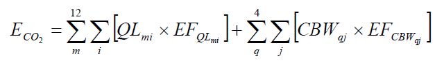
Where:
- ECO2
- Annual process CO2 emissions in tonnes/year.
- QLmi
- Quantity of lime type i produced in month m, tonnes.
- EFQLmi
- Emission factor of lime type i produced in month m, computed as specified in paragraph (b)(2) of this section, tonnes CO2/tonne lime.
- CBWqj
- Quantity of calcined byproduct and waste type j produced in quarter q, tonnes.
- EFCBW,qj
- Emission factor of calcined byproduct/waste type j produced in quarter q, computed as specified in paragraph (b)(3) of this section, tonnes CO2/tonne byproduct and waste.
Monthly Lime Emission Factor. Calculate a plant-specific lime emission factor (EFQL) for each type of lime and month based on the per cent of measured CaO and MgO content in lime and using Equation 170-2.
Equation 170-2:
EFQL = (ƒCaO × 0.785) + (ƒMgO × 1.092)
Where:
- EFQL
- Process CO2 emission factor for lime produced, tonnes CO2/tonne lime.
- ƒCaO
- CaO content of lime, calculated by subtracting CaO content of lime in uncalcined CaCO3 remaining in lime from total CaO content of lime, tonnes CaO/tonne lime
- 0.785
- Ratio of molecular weights of CO2 to CaO.
- ƒMgO
- MgO content of lime, calculated by subtracting MgO content of lime in uncalcined MgCO3 remaining in lime from total MgO content of lime, tonnes MgO/tonne lime.
- 1.092
- Ratio of molecular weights of CO2 to MgO
Quarterly Calcined Byproduct/Waste Emission Factor. The calcined byproduct/waste emission factor shall be calculated using Equation 170-3.
Equation 170-3:
EFCBW = (ƒCaO × 0.785) + (ƒMgO × 1.092)
Where:
- EFCBW
- Process CO2 Emission factor for calcined byproduct and waste, tonnes CO2/tonne calcined byproduct and waste.
- ƒCaO
- CaO content of byproduct and waste, calculated by subtracting CaO content of byproduct and waste in uncalcined CaCO3 remaining in calcined byproduct and waste from total CaO content of byproduct and waste, tonnes CaO/tonne byproduct and waste.
- 0.785
- Ratio of molecular weights of CO2 to CaO.
- ƒMgO
- MgO content of byproduct and waste, calculated by subtracting MgO content of byproduct and waste in uncalcined MgCO3 remaining in byproduct and waste from total MgO content of byproduct and waste, tonnes MgO/tonne byproduct and waste.
- 1.092
- Ratio of molecular weights of CO2 to MgO
Fuel Combustion Emissions in Kilns. Calculate CO2, CH4, and N2O emissions from stationary fuel combustion emissions following the calculation methodologies specified in ON.20. The person that primarily combusts biomass-derived fuels; and combusts fossil fuels only during periods of start-up, shut-down, or malfunction; may report CO2 emissions from fossil fuels using the Calculation methodology 1 in ON.23.“Pure” means that the biomass-derived fuels account for 97 per cent of the total amount of carbon in the fuels burned.
The person that reports CO2 emissions from kilns using continuous emissions monitoring systems pursuant to ON.173(a)(1) may report:
- Fuel combustion CO2 emissions in kilns by subtracting the total emissions calculated using ON.173(a)(1) from the process CO2 emissions calculated using ON.173(b); or
- Fuel combustion CO2 emissions in kilns using the Calculation Methodology 1 in ON.23 and fuel sampling based on the same plant techniques used for accounting purposes.
ON.174 Sampling, Analysis, and Measurement Requirements
- The person shall determine the chemical composition (CaO and MgO contents) of each type of lime and each type of calcined byproduct/waste according to the relevant methods and protocols contained in of this section. Samples for analysis of the calcium oxide and magnesium oxide content of each lime type and each calcined byproduct/waste type should be collected during the same month or quarter as the production data. At least one sample shall be collected monthly for each lime type produced during the month and quarterly for each calcined byproduct/waste type produced.
- ASTM C25.
- The National Lime Association’s CO2 Emissions Calculation Protocol for the Lime Industry English Units.
- Any of the other analytical methods listed in the Technical Reference Document section of this Guideline (section 5).
- The most appropriate method published by a consensus-based standards organization. If no appropriate method is published by a consensus-based standards organization, use industry standard methods, noting where such methods are used and what methods are used.
- The quantity of lime produced and sold is to be estimated monthly using direct measurements (such as rail and truck scales) of lime sales for each lime type, and adjusted to take into account the difference in beginning- and end-of-period inventories of each lime type. The inventory period shall be annual at a minimum. Equipment used to measure the production quantity shall be:
- calibrated according to the manufacturer’s instructions and
- maintained to achieve an accuracy of plus or minus 5%.
- The quantity of calcined byproduct/waste sold is to be estimated monthly using direct measurements (such as rail and truck scales) of calcined byproduct/waste sales for each calcined byproduct/waste type, and adjusted to take into account the difference in beginning- and end-of-period inventories of each calcined byproduct/waste type. The inventory period shall be annual at a minimum. The quantity of calcined byproduct/waste not sold is to be determined no less often than annually for each calcined/byproduct waste type using direct measurements (such as rail and truck scales), or a calcined byproduct/waste generation rate (i.e. calcined byproduct produced as a factor of lime production).
- The person shall follow the quality assurance/quality control procedures (including documentation) in National Lime Association’s CO2 Emissions Calculation Protocol for the Lime Industry English Units Version, February 5, 2008 Revision – National Lime Association.
ON.175 Procedures for Estimating Missing Data
Unavailable analytical Data
- Whenever analytical data relating to sampling is unavailable, the person shall, using the methods prescribed in ON.174, re-analyze the original sample, a backup sample or a replacement sample for the same measurement and sampling period.
Determination of quantity
- Whenever sampling and measurement data required by ON.174 for the calculation of emissions is missing the person shall ensure that the data is replaced using the following missing data procedures:
- When the missing data concerns carbon content, temperature, pressure or gas concentration, the person shall:
Determine the sampling or measurement rate using the following Equation 170-4:
Equation 170-4:
R = QSAct ⁄ QSRequired
Where:
- When the missing data concerns carbon content, temperature, pressure or gas concentration, the person shall:
- R
- Sampling or measurement rate that was used, expressed as a percentage
- QSAct
- Quantity of actual samples or measurements obtained by the person
- QSRequired
- Quantity of samples or measurements required under ON.174
- Replace the missing data as follows,
- If R ≥ 0.9: replace the missing data by the arithmetic mean of the sampling or measurement data from immediately before and after the missing data period. If no data is available from before the missing data period, the person shall use the first available data from after the missing data period;
- If 0.75 ≤ R < 0.9: replace the missing data by the highest data value sampled or analyzed during the reporting period for which the calculation is made;
- If R < 0.75: replace the missing data by the highest data value sampled or analyzed during the 3 preceding years;
- When the missing data concerns the consumption of carbon-containing raw material, consumption of ferrous scrap, annual consumption of molten iron, consumption of coking coal, consumption of flux material, consumption of direct reduced iron pellets, consumption of carbon electrodes, consumption of ore, quantity of slag produced, consumption of greenball pellets, production of fired pellets, production of coke oven gas, production of metallurgical coke, quantity of air pollution control residue collected, quantity of other coke oven by-products, the quantity of steel processed or produced, quantity of gas from basic oxygen furnaces transferred, the production of sinter, the production of iron or the quantity of non-metallic by-products, the replacement data shall be generated from best estimates based on all of the data relating to the processes.
- For all units subject to the requirements of ON.20 that monitor and report emissions using a CEMS, the missing data backfilling procedures in EPS 1/PG/7 shall be followed for CO2 concentration, stack gas flow rate, fuel flow rate, high heating value, and fuel carbon content.
ON.290 Magnesium Production
ON. 291 Activity Definition
For the purpose of this method, the following definitions apply:
- Cover gas
- means a greenhouse gas used to protect the surface of molten magnesium from rapid oxidation and burning in the presence of air and includes but is not limited to SF6 and HFC–134a.
- Carrier gas
- means a gas mixed with a cover gas to transport and dilute the cover gas.
- Heels
- means any material remaining in a tank following unloading, delivery, or discharge of the transported cargo.
- Magnesium producer
- means a person who engages in magnesium production
- Magnesium production
- has the same meaning as in the Regulation
ON.292 Greenhouse Gas Reporting Requirements
- A magnesium producer shall set out the following information, calculated for the calendar year using standard quantification methods ON.290- – ON.295, in an emission report prepared for a calendar year in respect of magnesium production:
- The total annual emissions of each greenhouse gas listed in Table 1 of the Regulation resulting from the use of the greenhouse gas as a cover or carrier gas in magnesium production expressed in tonnes of CO2e per year calculated using the methods in ON.293.
- the total annual quantity of magnesium produced or processed, by process type, in tonnes;
- An explanation of any change greater than 30 per cent in the facility’s cover gas usage rate from the previous calendar year.
- A description of any new melt protection technologies adopted to account for reduced or increased greenhouse gas emissions in the previous reporting period.
ON.293 Calculation of GHG Emissions
- A magnesium producer shall use Equation 290-1 or 290-2 to calculate the mass of GHG emissions from the consumption of cover or carrier gases expressed in tonnes,
Monitoring changes in container masses and inventories:
Equation 290-1:
Ex = (IB,x − IE,x + Ax − Dx) × 0.001Where:
- Ex
- Total GHG emissions from the consumption of cover or carrier gases expressed in tonnes
- IB,x
- Inventory of cover gas or carrier gas x stored in cylinders or other containers at the beginning of the reporting period, including heels expressed in kg;
- IE,x
- Inventory of each cover gas or carrier gas x stored in cylinders or other containers at the end of the reporting period, including heels expressed in kg;
- Ax
- Acquisitions of cover gas or carrier gas x during the reporting period, including heels in cylinders or other containers returned to the magnesium production or processing facility expressed in kg;.
- Dx
- Transfers of cover gas or carrier gas x off-site during the reporting period, including heels in cylinders or other containers returned by the magnesium production or processing facility to the gas supplier expressed in kg;
- 0.001
- Conversion factor from kg to tonnes; and
- x
- Each cover gas or carrier gas that is a GHG contained in Schedule 1 of the Regulation.
Monitoring changes in masses of individual containers as contents are used:
Equation 290-2:
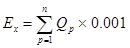
Where:
- Ex
- Total GHG emissions from the consumption of cover or carrier gases expressed in tonnes
- QP
- Mass of the cover or carrier gas consumed calculated in accordance with Equation 290-3 expressed in kg;
- n
- Number of cylinders or other containers in period p,;
- 0.001
- Conversion factor from kg to tonnes; and
For the purposes of Equation 290-2, the mass of the cover or carrier gas consumed over the period p for an individual container shall be estimated by using Equation 290-3:
Equation 290-3:
Qp = MB − ME
Where:
- Qp
- Mass of cover or carrier gas consumed over the period p
- MB
- Mass of the cylinder or container’s contents expressed in kg at the beginning of period p; and
- ME
- Mass of the cylinder or container’s contents expressed in kg at the end of period p.
- Notwithstandng (b) above, if a facility has mass flow controllers (MFC) and the capacity to track and record MFC measurements to estimate total gas usage, the mass of each cover or carrier gas monitored may be used as the value for Qp in Equation 290-2 expressed in kg.
ON.294 Sampling, Analysis, and Measurement Requirements
Determination of quantities of cover and carrier gases and mass flows
- The magnesium producer required to determine quantities of cover and carrier gases for the purposes of using this method shall determine changes in cylinder or container weights and inventories as follows:
- Using scales or load cells with an accuracy of 1 per cent of full scale or better, accounting for the tare weights of the cylinders or other containers or
- Using gas masses or weights provided by the gas supplier (e.g., for the contents of containers containing new gas or for the heels remaining in cylinders or other containers returned to the gas supplier) if the supplier provides documentation verifying that accuracy standards in (c) are met.
- The magnesium producer required to determine quantities of cover and carrier gases for the purposes of using Equations 290-2 and 290-3 shall monitor and record cylinder and other container identities and masses as follows:
- Track the identities and masses of cylinders and other containers leaving and entering storage with check-out and check-in sheets and procedures.
- Measure masses of cylinders and other containers returning to storage immediately before the cylinders or other containers are put back into storage.
- The magnesium producer required to monitor the mass flows of the cover or carrier gas into the gas distribution system for the purposes of ON.293(c) shall use gas flow meters or mass flow controllers, with an accuracy of 1 per cent of full scale or better.
Equipment Calibration
- The magnesium producer required to determine quantities of cover and carrier gases pursuant to this method shall calibrate all flow meters, scales, and load cells prior to its first use for the purposes of this method using calibration procedures specified by the equipment manufacturer.
- The magnesium producer required to determine quantities of cover and carrier gases pursuant to this method shall recalibrate equipment mentioned in (d) at the minimum frequency specified by the manufacturer.
- The person shall measure the magnesium production quantity. Equipment used to measure the production quantity shall be:
- calibrated according to the manufacturer’s instructions and
- maintained an accuracy of plus or minus 5%.
ON.295 Procedures for Missing Data
Determination of quantity
- Whenever sampling and measurement data required by ON.293 for the calculation of emissions is unavailable, the person shall ensure that the data is substituted using the following missing data procedures:
Replace missing data on the emissions of cover or carrier gases by multiplying magnesium production during the missing data period by the average cover or carrier gas usage rate calculated using Equation 290-4.
Equation 290-4:
Rx = (Cx ⁄ Mg) × 0.001Where:
- Rx
- Usage rate of a particular cover gas or carrier gas x over the period of comparable operation expressed in tonnes gas/tonne Mg;
- Cx
- Consumption of a particular cover gas or carrier gas x over the period of comparable operation expressed in kg;
- Mg
- Magnesium produced or fed into the process over the period of comparable operation expressed in tonnes;
- 0.001
- Conversion factor from kg to tonnes; and
- x
- Each cover gas or carrier gas that is a GHG listed in Schedule 1 of the Regulation.
- Unavailable weights: Where the calculation of the before and after weight of a cylinder or other container is required, and a precise weight is not available, the magnesium producer shall assume that the cylinder or other container, except for the heel, was emptied.
- Records for missing data: The magnesium producer shall ensure that where data is missing, the following information is recorded;
- the length of time the data was missing for each cover gas or carrier gas,
- the method used to estimate emissions in the absence of the data, and
- the quantity of emissions estimated using that method.
ON.280 Mobile Equipment Operation (for reference purposes only)
ON.281 Activity Definition
For the purposes of this standard quantification method:
- Mobile equipment operation
- means the operation, related to production as part of the normal operations of a facility, of mobile industrial equipment used for transportation or movement of substances, materials and products at the facility, including tractors, mobile cranes, log transfer equipment, mining machinery, graders, backhoes and bulldozers and excluding on-road vehicles within the meaning of the On-Road Vehicle and Engine Emission Regulations (Canada), aircraft and marine vessels.
- Person
- means a person that engages in mobile equipment operation.
- Mobile equipment operator
- means an owner and operator of a facility that has mobile equipment and who is required to report under s. 2(1) of the regulation.
- Mobile equipment
- means mobile industrial equipment used for on-site transportation or movement of substances, materials and products at the facility including tractors, mobile cranes, log transfer equipment, mining machinery, graders, backhoes and bulldozers but does not include on-road vehicles, aircrafts or marine vessel.
- On-road vehicle
- has the same meaning as in the On-Road Vehicle and Engine Emission Regulations (Canada)
ON.282 Greenhouse Gas Reporting Requirements
This standard quantification method is included for reference purposes only and the use of mandatory language, such as “shall”, throughout this method is also included for reference purpsoes only and is not intended to create any substantive obligatons.
- A person shall set out the following information, calculated for the calendar year using standard quantification methods ON.280 – ON.286, in an emission report prepared for a calendar year in respect of mobile equipment operation at a facility:
- The total annual CO2, CO2 from biomass, CH4 and N2O emissions that would result from the complete combustion of each fuel type used by all mobile sources at the facility calculated in accordance with ON.283 and ON 284 expressed in tonnes.
- The total annual quantity of each type of fuel used by all mobile equipment at the facility expressed in kilolitres calculated in accordance with ON.285.
ON.283 Calculation of CO2 Emissions
- The person shall use one of the following calculation methodologies to calculate the total annual CO2 emissions, including total annual CO2 emissions from biomass:
Calculation Methodology 1- Fossil Fuel Usage:
Equation 280-1:
EtotalCO2 = Qi × EFiWhere:
- EtotalCO2
- total annual CO2 emissions that would result from the complete combustion of each fuel type used by all mobile equipment at the facility expressed in tonnes;
- Qi
- total annual quantity of fuel i used in mobile equipment expressed in litres;
- EFi
- Emission factor for fuel i expressed in tonnes of CO2/litre
Calculation Methodology 2 – Hours of operation:
Step 1: Equation 280-2:
Ei,k CO2 = (hi,k × hpi,k × LFi,k × BSFCi,k) × EFi,CO2Step 2: Equation 280-3:
ETotal,i,CO2 = ∑kEi,k,CO2Where:
- Ei,k CO2
- Total annual CO2 emissions from mobile equipment k for fuel i expressed in tonnes;
- hi,k
- Total annual hours of operation for mobile equipment k for fuel i expressed in hours;
- hpi,k
- Rated equipment horsepower for mobile equipment k for fuel i expressed in horsepower;
- LFi,k
- Load factor for mobile equipment k for fuel i expressed in a range between 0 and 1;
- BSFCi,k
- Brake-specific fuel consumption for mobile equipment k for fuel i expressed in litres/horsepower-per hour;
- EFi,
- Emission factor for fuel i expressed in tonnes of CO2/litre.
- ETotal,i,CO2
- Total annual CO2 emissions that would result from the complete combustion of each fuel type used by all mobile equipment at the facility expressed in tonnes;
Calculation Methodology 3 - Environment Canada Reporting:
Determine the total annual CO2 emissions reported to Environment Canada’s Greenhouse Gas Emissions Reporting Program pursuant to any submissions that the person was required to make to the Federal government under section 46 or 71 of the Canadian Environmental Protection Act, 1999 for each fuel type used by all mobile sources at the facility expressed in tonnes.
ON.284 Calculation of CH4 and N2O Emissions
- The person shall use one of the following calculation methodologies to calculate the annual CH4 and N2O emissions:
Calculation Methodology 1- Fossil Fuel Usage:
Equation 280-4:
Etotal i,g = Qi × EFi,g × (1 ⁄ 106)Where:
- Etotal i,g
- Total annual emissions of greenhouse gas g (i.e. CH4 or N2O) from mobile equipment for fuel i expressed in tonnes;
- Qi
- Total annual quantity of fuel i expressed in litres;
- EFi,g
- Emission factor for CH4 or N2O for fuel i expressed in grams/litre;
- (1 ⁄ 106)
- Conversion factor from grams to tonnes.
Calculation Methodology 2 – Hours of Operation:
Step 1: Equation 280-5:
Ei,k,g = (hi,k × hp,i,k × LFi,k × BSFCi,k) × EFi,g × (1 ⁄ 106)Step 2: Equation 280-6:
ETotal, i, g = ∑kEi,g,kWhere:
- Ei,k,g
- Total annual greenhouse gas g (CH4 or N2O) emissions from mobile equipment k for fuel i expressed in tonnes;
- hi,k
- Total annual hours of operation for mobile equipment k for fuel i expressed in hours;
- hp,i,k
- Rated equipment horsepower for mobile equipment k for fuel i expressed in horsepower;
- LFi,k
- Load factor for mobile equipment k for fuel i expressed in a range between 0 and 1;
- BSFCi,k
- Brake-specific fuel consumption for mobile equipment k for fuel i expressed in litres/horsepower-per hour;
- EFi,g
- Emission factor for greenhouse gas g (i.e. CH4 or N2O) for fuel i as listed in ON.20 expressed in grams/litre;
- (1 ⁄ 106)
- Conversion factor from grams to metric tons;
- ETotal, i, g
- Total Annual emissions greenhouse gas g (CH4 or N2O) for fuel i expressed in tonnes.
Calculation Methodology 3 – Environment Canada Reporting:
Determine the total annual CH4 and N2O emissions reported to Environment Canada’s Greenhouse Gas Emissions Reporting Program pursuant to any submissions that the person was required to make to the Federal government under section 46 or 71 of the Canadian Environmental Protection Act, 1999 for each fuel type used by all mobile sources at the facility expressed in tonnes.
ON.285 Sampling, Analysis, and Measurement Requirements
Emission Factors:
- The person shall use one of the following emissions factors when using Methodology 1 and 2 in ON.283 and ON.284:
- The emission factor for the fuel type listed in ON.20, or
- A mobile-operator-specific emissions factor
Fuel Quantities:
- The person shall, on an annual basis, determine the fuel volume required in Methodology 1 in ON.283 and ON.284 by using vendor receipts in the calendar year, dipstick measurement, or other means.
- The person may use engineering estimates when determining the portion of the biofuel in a mixture of biofuel and fossil fuel for the purpose of Methodology 1 in ON.283 and ON.284.
Hours of Operation:
- The person shall use the records kept by the facility setting out the hours of operation for the mobile equipment subject to the report when using Methodology 2 in ON.283 and ON.284.
ON.286 Procedures for estimating missing data
- Where the missing data concerns fuel quantity, the person shall generate the replacement data from best estimates based on all of the data relating to the mobile equipment.
ON.400 Natural Gas Distribution
ON.401 Activity Definitions
For the purpose of this method, the following definitions apply:
- Custody transfer station
- means a location in Ontario at which natural gas ownership or control passes from one party to another, neither of which is the ultimate consumer.
- Distributor
- means a person who engages in natural gas distribution as defined in the Regulation.
- Rm3
- means cubic meters at a reference temperature of 15 degrees Celsius and at a pressure of 101.325 kilopascal.
ON.402 Greenhouse Gas Reporting Requirements
- The distributor shall set out the following information, calculated for the calendar year using standard quantification methods ON.400– ON.406, in an emission report prepared for a calendar year in respect of natural gas distribution:
- Annual CO2 emissions, expressed in tonnes, that would result from the complete combustion or oxidation of the quantities of natural gas provided to end-users, calculated in accordance with ON.403.
- Annual CH4 and N2O emissions, expressed in tonnes, that would result from the complete combustion or oxidation of the quantities of natural gas provided to end-users, calculated in accordance with ON.404.
- Annual quantity of natural gas, excluding any natural gas derived from biomass, received by the distributor at its custody transfer stations, expressed in Rm3.
- Annual quantity of natural gas, excluding any natural gas derived from biomass, that is placed into storage, expressed in Rm3.
- Annual quantity of natural gas, excluding any natural gas derived from biomass, that is withdrawn from storage, expressed in Rm3.
- Annual quantity of natural gas delivered to another distributor or exported out of Ontario, expressed in Rm3.
- Report the following information for each capped participant to which the person has supplied natural gas, including the distributor’s own operations for the purpose of engaging in general stationary combustion, during the calendar year:
- Organization name;
- Facility location;
- Annual quantity of natural gas delivered, expressed in Rm3.
ON.403 Calculation of CO2 Emissions
Natural Gas received at custody transfer stations
- A distributor shall use one of the following methods to calculate annual CO2 emissions that would result from the complete combustion or oxidation of the natural gas received at the custody transfer station “i” in the calendar year, expressed in tonnes.
Calculation Methodology 1. Use Equation 400-1 to calculate the annual CO2 emissions that would result from the complete combustion or oxidation of the natural gas received at the custody transfer station:
Equation 400-1:
CO2i = 0.001 × ∑NGh × HHVh × EFhWhere:
- CO2i
- Annual CO2 emissions from the complete combustion or oxidation of the natural gas received by the distributor at its custody transfer stations, expressed in tonnes.
- NGh
- Annual quantity of natural gas received, excluding any natural gas derived from biomass or gas that does not contain any carbon, at the custody transfer station in period “h”, expressed in Rm3.
- HHVh
- Default high heat value contained in Table 400-1 or a distributor-specific higher heating value determined in accordance with ON.405, expressed in GJ per Rm3 or GJ per litre.
- EFh
- Default CO2 emission factor contained in Table 400-1 or a distributor-specific CO2 emission factor determined in accordance with ON.405, expressed in kg of CO2 per GJ.
- 0.001
- Conversion factor from kilograms to tonnes.
Calculation Methodology 2. Use Equation 400-2 to calculate the annual CO2 emissions that would result from the complete combustion or oxidation of the natural gas received at the custody transfer station:
Equation 400-2:
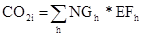
Where:
- CO2i
- Annual CO2 emissions from the complete combustion of the natural gas received by the distributor at its custody transfer stations, expressed in tonnes.
- NGh
- Annual quantity of natural gas received, excluding any natural gas derived from biomass or gas that does not contain any carbon, at the custody transfer station in period “h” , expressed in Rm3.
- EFh
- Default CO2 emission factor contained in Table 400-2 or a distributor-specific CO2 emission factor determined in accordance with ON.405, expressed in kg of CO2 per Rm3.
- In addition to the requirements in (a) above, each distributor shall calculate the following CO2 emissions, expressed in tonnes:
Use Equation 400-3 to calculate the annual CO2 emissions that would result from the complete combustion or oxidation of natural gas that is distributed to another distributor “j” or exported out of Ontario:
Equation 400-3:
CO2j = NGj × EFWhere:
- CO2j
- Annual CO2 emissions from the complete combustion of the natural gas that is distributed to another distributor or exported out of Ontario, expressed in tonnes.
- NGj
- Annual quantity of natural gas, excluding any natural gas derived from biomass or gas that does not contain any carbon, distributed to another distributor “j” or exported out of Ontario, expressed in Rm3.
- EF
- Default CO2 emission factor contained in Table 400-2 or a distributor-specific CO2 emission factor determined in accordance with ON.405, expressed in tonnes of CO2 per Rm3.
Use Equation 400-4 to calculate the annual CO2 emissions that would result from the complete combustion or oxidation of natural gas, excluding any natural gas derived from biomass, that is distributed to capped partcipants “k”
Equation 400-4:
CO2k = NGk × EFWhere:
- CO2k
- Annual CO2 emissions that would result from the complete combustion of the natural gas that is distributed to other persons required to report and verify emissions under the Regulation, expressed in tonnes.
- NGk
- Annual quantity of natural gas, excluding any natural gas derived from biomass or gas that does not contain any carbon, distributed to capped participant “k”.
- EF
- Default CO2 emission factor contained in Table 400-2 or a distributor-specific CO2 emission factor determined in accordance with ON.405, expressed in tonnes of CO2 per Rm3.
Use Equation 400-5 to calculate the annual CO2 emissions that would result from the complete combustion or oxidation of the quantity of natural gas that represents the net change in natural gas stored during the calendar year:
Equation 400-5:
CO2l = [Fuel1 − Fuel2] × EFWhere:
- CO2l
- Annual CO2 emissions that would result from the complete combustion of natural gas that represents the net change in natural gas stored within the calendar year, expressed in tonnes.
- Fuel1
- Annual quantity of natural gas, excluding any natural gas derived from biomass or gas that does not contain any carbon, put into storage after the custody transfer station during the calendar year, expressed in Rm3
- Fuel2
- Annual quantity of natural gas, excluding any natural gas derived from biomass or gas that does not contain any carbon, that is taken out of storage after the custody transfer station during the calendar year, expressed in Rm3.
- EF
- Default CO2 emission factor contained in Table 400-2 or a distributor-specific CO2 emission factor determined in accordance with ON.405 expressed in tonnes of CO2 per Rm3.
Use Equation 400-6 to calculate the total annual CO2 emissions.
Equation 400-6:
CO2ƒ = ∑CO2i − ∑CO2j − ∑CO2k − ∑CO2l
ON.404 Calculation of CH4 and N2O Emissions
A distributor shall use Equation 400-7 to calculate annual CH4 emissions and Equation 400-8 to calculate annual N2O emissions that would result from the complete combustion or oxidation of natural gas received at the custody transfer station, expressed in tonnes.
Equation 400-7:
CH4 = CO2f × EFCH4 × 0.000001 ÷ EFhEquation 400-8:
N2O = CO2f × EFN2O × 0.000001 ÷ EFhWhere:
- CH4
- Annual CH4 emissions, expressed in tonnes.
- N2O
- Annual N2O emissions, expressed in tonnes.
- EFh
- CO2 emission factor used to calculate CO2 emissions in ON.403(a), expressed in tonnes of CO2 per Rm3.
- EFCH4
- Default CH4 emisions factor contained in Table 20-4 using the value for “Residential, Construction, Commercial/Institutional, Agriculture”, expressed in grams of CH4 per Rm3.
- EFN2O
- Default N2O emisions factor contained in Table 20-4 using the value for “Residential, Construction, Commercial/Institutional, Agriculture”, expressed in grams of N2O per Rm3.
ON.405 Sampling, Analysis, and Measurement Requirements
- Determination of quantity of natural gas
- The distributor required to determine quantites of natural gas pursuant to this method shall determine those quantities using standard quantification practices used for:
- Billing purposes in the natural gas industry; or
- Non-billing purposes in the natural gas industry.
- If the distributor determines the quantities of natural gas using 1(ii), the minimum frequency of measurement shall be the same as the one used in the quantification practices under 1(i).
- The distributor required to determine quantities of natural gas for the purposes of using Equations 400-1, 400-2 or 400-3 of this method shall use the volume of natural gas measured at the custody transfer meter(s).
- The distributor refered to in (3) may use measurements or records of deliveries inplace of the the volume of natural gas measured at the custody transfer meter(s).
- The distributor required to determine quantities of natural gas for the purposes of using Equation 400-4 of this method shall measure the volume of natural gas at all customer meter(s) at the facility .
- The distributor required to determine quantities of natural gas for the purposes of using Equation 400-5 of this section shall measure natural gas as follows:
- Fuel1 shall be measured at the on-system storage injection meters and at the meters measuring natural gas to be liquefied.
- Fuel2 shall be measured at the meters used for measuring on-system storage withdrawals or LNG vaporization injection.
- The distributor required to determine quantites of natural gas pursuant to this method shall determine those quantities using standard quantification practices used for:
- Determination of high heating values (HHV).
- The distributor required to use Equation 400-1 shall, when using a distributor-specific HHV, calculate the HHV in accordance with an appropriate standard test published by a consensus-based standards organization using one of the following measurements:
- If the distributor takes its own HHV measurements in accordance with established business practices, then its own measurements shall be used.
- If the distributor does not make its own measurements according to established business practices, it shall use its delivering pipeline measurements.
- The distributor required to use Equation 400-1 shall, when using a distributor-specific HHV, calculate the HHV in accordance with an appropriate standard test published by a consensus-based standards organization using one of the following measurements:
- Determination of distributor-specific emission factors.
- A distributor using a distributor-specific emission factor in accodance with this method shall conduct compositional analysis using an appropriate standard method published by a consensus-based standards organization to determine the CO2 emission factor.
- Equipment Calibration (which may also be referred to as Equipment verification).
- A distributor required to determine quantities of natural gas in accordance with this method shall calibrate orifice, nozzle, and venturi flow meters:
- Prior to its first use for the purposes of this method; and
- Using in-situ calibration of the differential pressure (delta-P), total pressure and temperature transmitters.
- For flow meters used for natural gas, the distributor may follow the requirements under the laws and regulations of Measurement Canada for electricity and gas or as specified by the equipment manufacturer.
- A distributor required to determine quantities of natural gas pursuant to this method shall recalibrate equipment mentioned in (1)or (2) at the frequency specified by:
- Any applicable method listed in the Technical Reference Document section of this Guideline;
- The most appropriate method published by a consensus-based standards organization;
- Using methods and requirements in accordance with the requirements under the laws and regulation of Measurement Canada for electricity and gas; or
- The manufacturer’s directions.
- A distributor required to determine quantities of natural gas in accordance with this method shall calibrate orifice, nozzle, and venturi flow meters:
ON.406 Procedures for Estimating Missing Data
- Whenever a value for natural gas, HHV or EF is required by this method and is unavailable during a calendar year or part thereof, the distributor shall substitute a value for the missing data in accordance with the following:
- Substitute the missing quantity of natural gas with quantities derived from:
- The delivering pipeline metered deliveries at the custody transfer station or
- Nominations and scheduled delivery quantities.
- Substitute the missing HHV value with:
- Delivering pipeline measurements;
- The default HHV provided in Table 400-1; or,
- Where values relating to a distributor-specific emission factor are unavailable, substitute the missing EF value with the value from Table 400-1 or 400-2 as applicable.
- Substitute the missing quantity of natural gas with quantities derived from:
| Fuel | Default High Heating Value Factor | Default CO2 Emission Factor (kg CO2 /GJ) |
|---|---|---|
| Natural Gas | 0.038 GJ/m3 | 49.03 |
| Fuel | Unit | Default CO2 Emission Value (tonnes CO2/Unit) |
|---|---|---|
| Natural Gas | reference cubic metres (Rm3) | 0.001863 |
ON.310 Nitric Acid Production
ON.311 Activity Definition
For the purposes of this standard quantification method:
- Nitric acid production
- has the same meaning as in the Regulation.
- Person
- means a person that engages in nitric acid production.
ON.312 Greenhouse Gas Reporting Requirements
A person shall set out the following information, calculated for the calendar year using standard quantification methods ON.310 – ON.315, in an emission report prepared for a calendar year in respect of nitric acid production at a facility:
- Total N2O process emissions as required by this method (tonnes)
- Total CO2 emissions from the reducing agents used in the non-selective catalytic reduction units (tonnes CO2), calculated using ON.313(i).
- Total CH4 emissions from unreacted methane in reducing agents used in the non-selective catalytic reductionunit (tonnes CH4), calculate using ON.313(i).
- Annual nitric acid production from the nitric acid facility (tonnes, 100 per cent acid basis).
ON.313 Calculation of GHG emissions
- The person shall determine annual N2O process emissions from each nitric acid train according to paragraphs (a)(1) or (a)(2) of this section.
- Use a site-specific emission factor and production data according to paragraphs (b) through (h) of this section.
- Use a continuous monitoring system (CEMS).
- The person shall conduct an annual performance test according to paragraphs (b)(1) through (b)(2) of this section.
- The person is required to measure N2O emissions from the absorber tail gas vent for each nitric acid train or after the gas vent of the N2O abatement technology, using the methods specified in ON.314(b) through (d),.
- The person shall measure the production rate during the performance test and calculate the production rate for the test period in tonnes (100 per cent acid basis) per hour.
- The person shall determine an N2O emissions factor to use in Equation 310-3a or 310-3b of this section according to the following:
Using the results of the performance test in paragraph (b) of this section, the person shall calculate an average site-specific emission factor for each nitric acid train “t” according to Equation 310-1 of this section:
Equation 310-1:
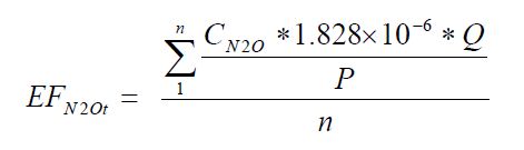
Where:
- EFN2Ot
- Average site-specific N2O emissions factor for nitric acid train “t” (kg N2O generated/tonne nitric acid produced, 100 per cent acid basis).
- CN2O
- N2O concentration for each test run during the performance test (ppm N2O).
- 1.828×10⁻⁶
- Conversion factor (kg/dSm3-ppm N2O).
- Q
- Volumetric flow rate of effluent gas for each test run during the performance test (dSm3/hr).
- P
- Production rate for each test run during the performance test (tonnes nitric acid produced per hour, 100 per cent acid basis).
- n
- Number of test runs.
- If applicable, the person is required to determine the destruction efficiency for each N2O abatement technology according to paragraphs (d)(1), (d)(2), or (d)(3) of this section.
- Use the manufacturer’s specified destruction efficiency.
- Estimate the destruction efficiency through process knowledge. Examples of information that could constitute process knowledge include calculations based on material balances, process stoichiometry, or previous test results provided the results are still relevant to the current vent stream conditions. The person shall document how process knowledge (if applicable) was used to determine the destruction efficiency.
- Calculate the destruction efficiency by conducting an additional performance test on the emissions stream following the N2O abatement technology.
If applicable, the person is required to determine the abatement factor for each N2O abatement technology. The abatement factor is calculated for each nitric acid train according to Equation 310-2 of this section.
Equation 310-2:
AFN t = Pa t Abate ⁄ Pa tWhere:
- AFN t
- Abatement factor of N2O abatement technology at nitric acid train “t” (fraction of annual production that abatement technology is operating).
- Pa t
- Total annual nitric acid production from nitric acid train “t” (tonne acid produced, 100 per cent acid basis).
- Pa t Abate
- Annual nitric acid production from nitric acid train “t” during which N2O abatement was used (tonne acid produced, 100 per cent acid basis).
- The person shall determine the annual amount of nitric acid produced and the annual amount of nitric acid produced while each N2O abatement technology is operating from each nitric acid train (100 per cent basis).
The person shall calculate N2O emissions for each nitric acid train by multiplying the emissions factor (determined in Equation 310-1 of this section) by the annual nitric acid production and accounting for N2O abatement, according to Equation 310-3a (for measurements before the abatement technology) or 310-3b (for measurements after the abatement technology) of this section:
Equation 310-3a:
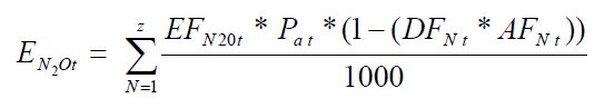
Equation 310-3b:
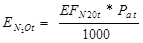
Where:
- EN2Ot
- N2O mass emissions per year for nitric acid train “t” (tonnes).
- EFN2Ot
- Average site-specific N2O emissions factor for nitric acid train ”t” (kg N2O generated/tonne acid produced, 100 per cent acid basis).
- Pa t
- Annual nitric acid production from the train “t” (tonne acid produced, 100 per cent acid basis).
- DFN t
- Destruction efficiency of N2O abatement technology N that is used on nitric acid train “t” (per cent of N2O removed from air stream).
- AFN t
- Abatement factor of N2O abatement technology for nitric acid train “t” (fraction of annual production that abatement technology is operating).
- 1000
- Conversion factor (kg/tonne).
- z
- Number of different N2O abatement technologies.
The person shall determine the annual nitric acid production emissions combined from all nitric acid trains at the facility using Equation 310-4 of this section:
Equation 310-4:
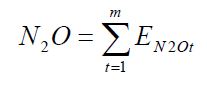
Where:
- N2O
- Annual process N2O emissions from nitric acid production facility (tonnes)
- EN2Ot
- N2O mass emissions per year for nitric acid train “t” (tonnes).
- m
- Number of nitric acid trains.
The person shall determine the annual emissions of CO2 and CH4 from reducing agents used in the non-selective catalytic reduction (NSCR) unit using Equations 310-5 and 310-6 of this section.
Equation 310-5:
Era_CO2 = Qa × (1 − Ms) × Ca × 3.664Equation 310-6:
Era_CH4 = Qa × (Ms) × CCH4Where:
- Era_CO2
- Annual CO2 emissions from other reducing agents or material used (tonnes);
- Era_CH4
- Annual CH4 emissions from unreacted methane in the reducing agent (tonnes)
- Qa
- Annual quantity of reducing agents or material used in the NSCR unit expressed in tonnes if it is a solid, Rm3 at reference temperature and pressure conditions as used by the facility if it is a gas, or kilolitres if it is a liquid;
- Ms
- Fraction of reducing agents or materials that did not react in the NSCR unit based on engineering estimates or design;
- Ca
- Carbon content of reducing agents or material used expressed in tonnes carbon per tonne of solid, tonnes carbon per Rm3 of gas, or tonnes carbon per kilolitre of liquid.;
- CCH4
- methane content of the reducing agent or material used expressed in tonnes methane per tonne of solid, tonnes of methane per Rm3 of gas, or tonnes methane per kiloliter of liquid;
- 3.664
- ratio of molecular weights, carbon dioxide to carbon.
ON.314 Sampling, Analysis, and Measurement Requirements
- The person shall conduct a new performance test and calculate a new site-specific emissions factor as specified in the following paragraphs.
- Conduct the performance test at least once per year.
- Conduct the performance test when the nitric acid production process is changed, specifically when abatement equipment is installed.
- The person shall measure the N2O concentration during the performance test using one of the following methods.
- EPA Method 320 at 40 CFR part 63, appendix A, Measurement of Vapor Phase Organic and Inorganic Emissions by Extractive Fourier Transform Infrared (FTIR) Spectroscopy.
- ASTM D6348.
- A method based on the use of non-dispersive infrared (NDIR) analyzer within a stack monitoring system where the method is equivalent to EPA method 320, any equivalent method published by Environment Canada or other Provinces.
- The most appropriate method published by a consensus-based standards organization, if such a method exists.
- If no appropriate method is published by a consensus-based standards organization, use industry standard methods, noting where such methods are used and what methods are used.
- The person shall determine the production rate(s) (100 per cent basis) from each nitric acid train during the performance test according to one of the following methods.
- Direct measurement of production and concentration (such as using flow meters, weigh scales, for production and concentration measurements).
- Existing plant procedures used for accounting purposes (i.e. dedicated tank-level and acid concentration measurements).
- The person shall conduct all performance tests in conjunction with the applicable methods. For each test, the facility shall prepare an emission factor determination report that shall include the following items.
- Analysis of samples, determination of emissions, and raw data.
- All information and data used to derive the emissions factor(s).
- The production rate during each test and how it was determined.
- The person shall determine the monthly nitric acid production quanity and the monthly nitric acid production quantity during which N2O abatement technology is operating from each nitric acid train according to the methods in paragraphs (c)(1) or (c)(2) of this section. Equipment used to measure the production quantity shall be:
- calibrated according to the manufacturer’s instructions and
- maintained to achieve an accuracy of plus or minus 5%.
- The person shall determine the annual nitric acid production quantity and the annual nitric acid production quantity during which N2O abatement technology is operating for each train by summing the respective monthly nitric acid production quantities. Equipment used to measure the production quantity shall be:
- calibrated according to the manufacturer’s instructions and
- maintained to achieve an accuracy of plus or minus 5%.
ON.315 Procedures for Estimating Missing Data
Unavailable analytical Data
- Whenever analytical data relating to sampling is unavailable, the person shall, using the methods prescribed in ON.314, re-analyze the original sample, a backup sample or a replacement sample for the same measurement and sampling period.
Determination of quantity
- Whenever sampling and measurement data required by ON.314 for the calculation of emissions is missing the person shall ensure that the data is replaced using the following missing data procedures:
- When data determined on the basis of the performance test provided for in ON.314 is missing, conduct a new performance test;
- When the missing data concerns carbon content, temperature, pressure or gas concentration, other than data prescribed in the performance test the person shall:
Determine the sampling or measurement rate using the following Equation 310-7:
Equation 310-7:
R = QSAct ⁄ QSRequired
Where:
- R
- Sampling or measurement rate that was used, expressed as a percentage
- QSAct
- Quantity of actual samples or measurements obtained by the person
- QSRequired
- Quantity of samples or measurements required under ON.314
- Replace the missing data as follows,
- If R ≥ 0.9: replace the missing data by the arithmetic mean of the sampling or measurement data from immediately before and after the missing data period. If no data is available from before the missing data period, the person shall use the first available data from after the missing data period;
- If 0.75 ≤ R < 0.9: replace the missing data by the highest data value sampled or analyzed during the reporting period for which the calculation is made;
- If R < 0.75: replace the missing data by the highest data value sampled or analyzed during the 3 preceding years;
- When the missing data concerns the consumption of carbon-containing raw material, consumption of ferrous scrap, annual consumption of molten iron, consumption of coking coal, consumption of flux material, consumption of direct reduced iron pellets, consumption of carbon electrodes, consumption of ore, quantity of slag produced, consumption of greenball pellets, production of fired pellets, production of coke oven gas, production of metallurgical coke, quantity of air pollution control residue collected, quantity of other coke oven by-products, the quantity of steel processed or produced, quantity of gas from basic oxygen furnaces transferred, the production of sinter, the production of iron or the quantity of non-metallic by-products, the replacement data shall be generated from best estimates based on all of the data relating to the processes.
- For all units subject to the requirements of ON.20 that monitor and report emissions using a CEMS, the missing data backfilling procedures in EPS 1/PG/7 shall be followed for CO2 concentration, stack gas flow rate, fuel flow rate, high heating value, and fuel carbon content.
ON.230 Operation of Equipment for a Transmission System or a Distribution System (Electricity)
ON.231 Activity Definition
For the purposes of this standard quantification method:
- Automated mass-flow measurement
- means the use of mass-flow meters attached to electrical power distribution equipment to directly measure the amount of SF6 added to equipment.
- Electricity transmission and distribution
- has the same meaning as “operation of equipment for a transmission system or a distribution system (electricity)” in the Regulation.
- Person
- means a person that engages in electricity transmission or distribution.
- PFC
- means perfluoroethane, perfluoropropane, perfluorobutane, perfluorocyclobutane, perfluoropentane, perfluorohexane.
- Storage containers
- includes cylinders, gas carts, and other storage containers, but does not include electrical power distribution equipment.
- Total nameplate capacity
- means the full and proper charge of electrical power distribution equipment.
- Weigh-scale measurement
- means measuring the SF6 or PFC in a storage container before and after its contents are added to electrical power distribution equipment with the difference being equal to the SF6 or PFC added to the equipment.
ON.232 Greenhouse Gas Reporting Requirements
A person shall set out the following information, calculated for the calendar year using standard quantification methods ON.230 – ON.235, in an emission report prepared for a calendar year in respect of electricity transmission and distribution at a facility:
- The SF6 and PFC emissions from electricity transmission and distribution and distribution calculated in accordance with ON.233(a) and (b).
ON.233 Calculation of SF6 and PFC Emissions
- A person shall use one of the following calculation methodologies to calculate SF6 emissions
- Mass Balance Methodology.
Calculate the change in inventory of SF6 in storage using Equation 230-1:
Equation 230-1:
ΔSInv = SInv-Begin − SInv-End
Where:
- Mass Balance Methodology.
- ΔSInv
- Change in inventory of SF6 in storage expressed in kilograms
- SInv-Begin
- Quantity of SF6 in storage at the beginning of the reporting period expressed in kilograms;
- SInv-End
- Quantity of SF6 in storage at the end of the reporting period expressed in kilograms
Calculate the amount of all SF6 acquired during the year that is contained either in storage containers or in electrical power distribution equipment using Equation 230-2:
Equation 230-2:
SPA = SCyl + SEquip + SRecyc-ret
Where:
- SPA
- Sum of all SF6 acquired during the year that is contained either in storage containers or in electrical power distribution equipment expressed in kilograms;
- SCyl
- Quantity of SF6 in storage containers obtained from producers or distributors expressed in kilograms;
- SEquip
- Quantity of SF6 stored or contained inside equipment provided by electrical power distribution equipment manufacturers expressed in kilograms;
- SRecyc-ret
- Quantity of SF6 returned to site after off-site recycling expressed in kilograms.
Calculate the sum of all SF6 transferred out of the facility during the year either in storage containers or in electrical power distribution equipment using Equation 230-3:
Equation 230-3:
SSD = SSales + SReturns + SDestruct + SRecyc-off
Where:
- SSD
- Sum of all SF6 transferred out of the facility during the year either in storage containers or in electrical power distribution equipment expressed in kilograms;
- SSales
- Quantity of SF6 sold or transferred to other facilities including SF6 that is left in electrical power distribution equipment that is sold expressed in kilograms;
- SReturns
- Quantity of SF6 returned to suppliers expressed in kilograms;
- SDestruct
- Quantity of SF6 sent to destruction facilities expressed in kilograms;
- SRecyc-off
- Quantity of SF6 sent off-site for recycling expressed in kilograms.
Calculate the net increase in total nameplate capacity of electrical power distribution equipment that uses SF6 using Equation 230-4.
Equation 230-4:
ΔSCap = SCap-new − SCap-retire
Where:
- ΔSCap
- Net increase in total nameplate capacity of electrical power distribution equipment that uses SF6 expressed in kilograms
- SCap-new
- Total nameplate capacity of new electrical power distribution equipment at proper full charge expressed in kilograms;
- SCap-retire
- Total nameplate capacity of electrical power distribution equipment that has been retired, sold or transferred at proper full charge expressed in kilograms.
Calculate total emissions for the reporting period using Equation 230-5:
Equation 230-5:
S = (ΔSInv + SPA − SSD − ΔSCap) ⁄ 1000
Where:
- S
- Total annual SF6 emissions expressed in tonnes;
- ΔSInv
- Change in inventory of SF6 in storage expressed in kilograms calculated in accordance with Equation 230-1;
- SPA
- Sum of all SF6 acquired that is contained either in storage containers or in electrical power distribution equipment expressed in kilograms, calculated in accordance with Equation 230-2;
- SSD
- Sum of all SF6 transferred out of the facility during the year that is contained either in storage containers or in electrical power distribution equipment expressed in kilograms calculated in accordance with Equation 230-3;
- ΔSCap
- Net increase in total nameplate capacity of electrical power distribution equipment using SF6 expressed in kilograms calculated in accordance with Equation 230-4
- 1000
- Factor to convert kilograms to tonnes.
- Direct Measurement Methodology.
SF6 emissions from the operations phase shall be calculated by directly measuring the mass of SF6 added to electrical power distribution equipment during the operation phase using automated mass-flow measurement or weigh-scale measurement in accordance with Equation 230-6:
Equation 230-6:

Where:
- SO
- Annual SF6 emissions during the operation phase expressed in kilograms;
- N
- Number of SF6 additions in a given year;
- Si
- SF6 added to electrical power distribution equipment during addition i, expressed in kilograms
SF6 emissions from the decommissioning phase shall be calculated by directly measuring the amount of SF6 collected from any decommissioned electrical power distribution equipment calculated in accordance with Equation 230-7:
Equation 230-7:
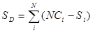
Where:
- SO
- Annual SF6 emissions during decommissioning phase expressed in kilograms;
- N
- Number of units of electrical power distribution equipment decommissioned in a given year;
- NCi
- Nameplate capacity of decommissioned electrical power distribution equipment i, expressed in kilograms;
- Si
- SF6 collected from decommissioned electrical power distribution equipment i, expressed in kilograms.
Total annual SF6 emissions are calculated according to Equation 230-8:
Equation 230-8:

Where:
- S
- Annual SF6 emissions expressed in tonnes;
- SO
- Annual SF6 emissions during operation phase expressed in kilograms;
- SD
- Annual SF6 emissions during decommissioning phase expressed in kilograms.
- A person shall use the methods in (a) to calculate the emissions from PFCs, substituting PFCs for SF6 and making all other necessary substitutions in Equations 230-1 through 230-8.
ON.234 Sampling, Analysis, and Measurement Requirements
- When using the calculation methodology in ON.233(a)(1), the person shall determine changes in cylinder or container weights and inventories as follows:
- Using scales or load cells with an accuracy of 1 per cent of full scale or better, accounting for the tare weights of the cylinders or other containers; or
- Using gas masses or weights provided by the gas supplier (e.g., for the contents of containers containing new gas or for the heels remaining in cylinders or other containers returned to the gas supplier) if the supplier provides documentation verifying that accuracy standards in (c) are met.
- When using the calculation methodology in ON.233(a)(1), a person shall monitor and record cylinder and other container identities and masses as follows:
- Track the identities and masses of cylinders and other containers leaving and entering storage with check-out and check-in sheets and procedures.
- Measure masses of cylinders and other containers returning to storage immediately before the cylinders or other containers are put back into storage.
- When using the calculation methodologies in ON.233(a)(2) or the corresponding method required by ON.233 (b), a person shall measure additions of SF6 or PFCs during the operation phase using a measuring instrument such as a flowmeter or weigh scale.
- When using the calculation methodologies in ON.233(a)(2) or the corresponding method required by ON.233 (b), a person shall calibrate equipment used to measure the mass of SF6 or PFCs as follows.
- For automated mass-flow measurement, equipment shall be calibrated according to the calibration procedure specified by manufacturer.
- For weigh-scale measurement, equipment shall be calibrated every 6 months by weighing objects of pre-determined mass and zeroing the weigh scale accordingly.
ON.235 Procedures for Estimating Missing Data
Unavailable analytical Data
- Whenever analytical data relating to sampling is unavailable, the person shall, using the methods prescribed in ON.234, re-analyze the original sample, a backup sample or a replacement sample for the same measurement and sampling period.
Determination of quantity
- Whenever sampling and measurement data required by ON.234 for the calculation of emissions is unavailable the person shall ensure that the data is substituted using the following missing data procedures:
Determine the sampling or measurement rate that was used using Equation 230-9:
Equation 230-9:
R = QSAct ⁄ QSRequired
Where:
- R
- Sampling or measurement rate that was used, expressed as a percentage
- QSAct
- Quantity of actual samples or measurements obtained by the person
- QSRequired
- Quantity of samples or measurements required under ON.230
- Replace the missing data as follows,
- If R ≥ 0.9: replace the missing data by the arithmetic mean of the sampling or measurement data from immediately before and after the missing data period. If no data is available from before the missing data period, the person shall use the first available data from after the missing data period;
- If 0.75 ≤ R < 0.9: replace the missing data by the highest data value sampled or analyzed during the reporting period for which the calculation is made;
- If R < 0.75: replace the missing data by the highest data value sampled or analyzed during the 3 preceding years;
- When the missing data concerns gas quantity, the person shall generate the replacement data from best estimates based on all of the data relating to the processes.
- When the missing data relates to electrical power distribution equipment capacity, the person shall estimate the replacement data on the basis of an equivalent nominal SF6 and PFC gas capacity, and on repair, replacement and maintenance data for similar pieces of equipment.
ON.350 Operation of Equipment Related to Natural Gas
ON.351 Activity Definition
For the purposes of this standard quantification method:
- Blowdown vent stack emissions
- mean natural gas and/or CO2 released due to maintenance and/or blowdown operations including compressor blowdown and emergency shut-down (ESD) system testing.
- Calibrated bag
- means a flexible, non-elastic, anti-static bag of a calibrated volume that can be affixed to a emitting source such that the emissions inflate the bag to its calibrated volume.
- Centrifugal compressor
- means any equipment that increases the pressure of a process natural gas or CO2 by centrifugal action, employing rotating movement of the driven shaft.
- Centrifugal compressor dry seals
- mean a series of rings around the compressor shaft where it exits the compressor case that operates mechanically under the opposing forces to prevent natural gas or CO2 from escaping to the atmosphere.
- Centrifugal compressor dry seals emissions
- mean natural gas or CO2 released from a dry seal vent pipe and/or the seal face around the rotating shaft where it exits one or both ends of the compressor case.
- Centrifugal compressor wet seal degassing venting emissions
- mean emissions that occur when the high-pressure oil barriers for centrifugal compressors are depressurized to release absorbed natural gas or CO2. High-pressure oil is used as a barrier against escaping gas in centrifugal compressor shafts. Very little gas escapes through the oil barrier, but under high pressure, considerably more gas is absorbed by the oil. The seal oil is purged of the absorbed gas (using heaters, flash tanks, and degassing techniques) and recirculated. The separated gas is commonly vented to the atmosphere.
- Component
- means each metal to metal joint or seal of non-welded connection separated by a compression gasket, screwed thread (with or without thread sealing compound), metal to metal compression, or fluid barrier through which natural gas or liquid can escape to the atmosphere.
- Compressor
- means any machine for raising the pressure of a natural gas by drawing in low pressure natural gas and discharging significantly higher pressure natural gas.
- Continuous bleed
- means a continuous flow of pneumatic supply gas to the process measurement device (e.g. level control, temperature control, pressure control) where the supply gas pressure is modulated by the process condition, and then flows to the valve controller where the signal is compared with the process set-point to adjust gas pressure in the valve actuator.
- Custody-transfer
- means the transfer of product from one gas company to another gas company, excluding transfers between companies who have same parent company.
- Damage events
- means damages to gas pipelines and surface facilities resulting from natural causes or third party incidents. Natural causes include corrosion, abrasion, rock damage, frost heaving or settling. Third party damages may include hits on surface facilities and dig-ins. Specific examples of dig-ins include grader/dozer/scraper excavation, demolition/breakout, general agriculture, driving bars/stakes/posts/anchors, backhoe/trackhoe excavation, ditch shaping, snow removal, landscaping/tree planting, hand excavation, bobcat/loader excavation, saw cutting, cable/pipe plowing, vertical augering/drilling, trencher excavation, blasting/vibrosis, deep tillage, horizontal augering/boring, and other such anthropogenic ground disturbances.
- De-methanizer
- means the natural gas processing unit that separates methane-rich residue gas from the heavier hydrocarbons (e.g., ethane, propane, butane, pentane-plus) in feed natural gas stream.
- Equipment leak detection
- means the process of identifying emissions from equipment, components, and other point sources.
- Farm taps
- mean pressure regulation stations that deliver gas directly from transmission pipelines to generally rural customers.
- Field gas
- means natural gas extracted from a production well prior to its entering the first stage of processing, such as dehydration.
- Flare
- for the purposes of ON.350, means a combustion device, whether at ground level or elevated, that uses an open or closed flame to combust waste gases without energy recovery.
- Flare combustion efficiency
- means the fraction of natural gas, on a volume or mole basis, that is combusted at the flare burner tip.
- Fugitive emissions
- means the unintended or incidental emissions of greenhouse gases from the transmission, processing, storage, use or transportation of fossil fuels, greenhouse gases, or other liquids or gases.
- Fugitive equipment leaks
- means those fugitive emissions which could not reasonably pass through a stack, chimney, vent, or other functionally-equivalent opening.
- Gas conditions
- mean the actual temperature, volume, and pressure of a gas sample.
- High-bleed pneumatic devices
- means automated continuous bleed control devices powered by pressurized natural gas and used for maintaining a process condition such as liquid level, pressure, delta-pressure and temperature. Part of the gas power stream which is regulated by the process condition flows to a valve actuator controller where it vents (bleeds) to the atmosphere at a rate in excess of 0.17 standard cubic meters per hour.
- Intermittent-bleed pneumatic devices
- mean automated flow control devices powered by pressurized natural gas and used for maintaining a process condition such as liquid level, pressure, delta-pressure and temperature. These are snap-acting or throttling devices that discharge the full volume of the actuator intermittently when control action is necessary, but not bleed continuously.
- Liquefied natural gas (LNG)
- means natural gas that has been liquefied by reducing its temperature to -162 degrees Celsius at atmospheric pressure.
- Liquefied natural gas (LNG) storage
- means LNG storage means onshore LNG storage vessels located above ground, equipment for liquefying natural gas, compressors to capture and re- liquefy boil-off-gas, re-condensers, and vapourization units for re-gasification of the liquefied natural gas.
- LNG boiloff gas
- means natural gas in the gaseous phase that vents from LNG storage tanks due to ambient heat leakage through the tank insulation and heat energy dissipated in the LNG by internal pumps.
- LNG import and export equipment
- means LNG import equipment means all onshore or offshore equipment that receives imported LNG via ocean transport, stores LNG, re-gasifies LNG, and delivers re-gasified natural gas to a natural gas transmission or distribution system. LNG export equipment means all onshore or offshore equipment that receives natural gas, liquefies natural gas, stores LNG, and transfers the LNG via ocean transportation to any location, including locations in Canada.
- Low-bleed pneumatic devices
- mean automated control devices powered by pressurized natural gas and used for maintaining a process condition such as liquid level, pressure, delta- pressure and temperature. Part of the gas power stream which is regulated by the process condition flows to a valve actuator controller where it vents (bleeds) to the atmosphere at a rate equal to or less than 0.17 standard cubic meters per hour.
- Meter-regulating station
- means a station that meters the flow rate, regulates the pressure, or both, of natural gas in a natural gas distribution system. This does not include customer meters, customer regulators, or farm taps.
- Natural gas distribution
- means natural gas distribution means of all natural gas equipment downstream of gate station inlet valves where pressure reduction and/or measuring occurs for eventual delivery of natural gas to consumers. Some natural gas distribution systems receive gas from gas batteries rather than from transmission pipelines and typically transport odourized natural gas.
- Natural gas pneumatic pump
- means a pump that uses pressurized natural gas to move a piston or diaphragm, which pumps liquids on the opposite side of the piston or diaphragm.
- Natural gas transmission pipelines
- means natural gas transmission pipelines means a high pressure pipeline (and associated equipment) transporting sellable quality natural gas from production or natural gas processing to natural gas distribution systems before delivery to customers. In some cases natural gas is delivered directly from natural gas transmission pipelines to farms and industrial end users along the pipeline route.
- Onshore natural gas transmission compression
- means onshore natural gas transmission compression means any stationary combination of compressors that move natural gas at elevated pressure from production fields or natural gas processing facilities in transmission pipelines to natural gas distribution pipelines, into storage or at times directly to industrial customers or farms located along the pipeline route. In addition, transmission compressor station may include equipment for liquids separation, natural gas dehydration, and tanks for the storage of water and hydrocarbon liquids. Residue (sales) gas compression operated by natural gas processing facilities are included in the onshore natural gas processing segment and are excluded from this segment.
- Operation of equiment related to natural gas
- has the same meaning as in the Regulation.
- Operating pressure
- means the containment pressure that characterizes the normal state of gas or liquid inside a particular process, pipeline, vessel or tank.
- Person
- means a person that engages in operation of equipment relatedto natural gas.
- Pump means
- a device used to raise pressure, drive, or increase flow of liquid streams in closed or open conduits.
- Pump seals
- means any seal on a pump drive shaft used to keep methane and/or carbon dioxide containing light liquids from escaping the inside of a pump case to the atmosphere.
- Pump seal emissions
- means hydrocarbon gas released from the seal face between the pump internal chamber and the atmosphere.
- Reciprocating compressor
- means a piece of equipment that increases the pressure of a gas stream by positive displacement, employing linear movement of a shaft driving a piston in a cylinder.
- Reciprocating compressor rod packing
- means a series of flexible rings in machined metal cups that fit around the reciprocating compressor piston rod to create a seal limiting the amount of the compressed gas stream that escapes to the atmosphere.
- Re-condenser
- means heat exchangers that cool compressed boil-off gas to a temperature that will condense natural gas to a liquid.
- Reservoir
- means a porous and permeable underground natural formation containing significant quantities of hydrocarbon liquids and/or gases.
- Underground natural gas storage
- means underground natural gas storage means subsurface storage, including depleted gas or oil reservoirs and salt dome caverns that store natural gas that has been transferred from its original location for the primary purpose of load balancing (the process of equalizing the receipt and delivery of natural gas); natural gas underground storage processes and operations (including compression, dehydration and flow measurement, and excluding transmission pipelines); and all the wellheads connected to the compression units located at the facility that inject and recover natural gas into and from the underground reservoirs.
- Vapour recovery system
- means any equipment located at the source of potential gas emissions to the atmosphere or to a flare, that is composed of piping, connections, and, if necessary, flow-inducing devices, and that is used for routing the gas back into the process as a product and/or fuel.
- Vapourization unit
- means a process unit that performs controlled heat input to vapourize LNG to supply transmission and distribution pipelines or consumers with natural gas.
ON.352 Greenhouse Gas Reporting Requirements
- A person shall set out the following information, calculated for the calendar year using standard quantification methods ON.350 – ON.355, in an emission report prepared for a calendar year in respect of Operation of equipment related to natural gas:
- CO2 and CH4 (and N2O, if applicable) emissions (in tonnes) from each industry segment specified in paragraph (b) through (f) of this section.
- For onshore natural gas transmission compression and natural gas transmission pipelines, report CO2, CH4 and N2O emissions from the following sources:
- Compressor venting (from the following sources):
- Reciprocating compressors in accordance with ON.353(a)(9).
- Centrifugal compressors in accordance with ON.353(a)(8).
- Blowdown vent stacks in accordance with ON.353(a)(5).
- Natural gas continuous high-bleed pneumatic devices in accordance with ON.353(a)(1).
- Natural gas pneumatic pumps in accordance with ON.353(a)(2).
- Natural gas continuous low-bleed pneumatic device venting in accordance with ON.353(a)(3).
- Natural gas intermittent (low and high) bleed pneumatic device (including compressor starters) venting in accordance with ON.353(a)(4).
- Other venting emission sources in accordance with ON.353(a)(15).
- Compressor fugitive equipment leaks from valves, connectors, open ended lines, pressure relief valves and meters in accordance with ON.353(a)(10) or ON.353(a)(11).
- Compressor station flaring in accordance with ON.353(a)(7).
- Compressor other fugitive emission sources in accordance with ON.353(a)(15).
- Pipeline flaring in accordance with ON.353(a)(7).
- Pipeline below grade meters and regulators and valve fugitives in accordance with ON.353(a)(11).
- Pipeline other fugitive emission sources not covered in (b)(5), (b)(6), or (b)(10) (including, but not limited to, farm taps <=700 kPa, pipe leaks, and customer meter sets)** in accordance with ON.353(a)(15).
- Pipeline other venting emission sources in accordance with ON.353(a)(15).
- Transmission storage tanks in accordance with ON.353(a)(16).
- Damage events in accordance with ON.353(a)(6).
- Compressor venting (from the following sources):
- For underground natural gas storage, report CO2, CH4 and N2O emissions from the following sources:
- Venting (from the following sources):
- Reciprocating compressors in accordance with ON.353(a)(9).
- Centrifugal compressors in accordance with ON.353(a)(8).
- Natural gas continuous high-bleed pneumatic devices in accordance with ON.353(a)(1).
- Natural gas pneumatic pumps in accordance with ON.353(a)(2).
- Natural gas continuous low-bleed pneumatic device venting in accordance with ON.353(a)(3).
- Natural gas intermittent (low and high) bleed pneumatic device (including compressor starters) venting in accordance with ON.353(a)(4).
- Other venting emission sources in accordance with ON.353(a)(15).
- Fugitive equipment leaks from valves, connectors, open ended lines, pressure relief valves and meters in accordance with ON.353(a)(10), ON.353(a)(11).
- Flares in accordance with ON.353(a)(7).
- Other fugitive emission sources. ON.353(a)(15).
- Venting (from the following sources):
- For LNG storage, report CO2, CH4 and N2O emissions from the following sources:
- Venting (from the following sources):
- Reciprocating compressors in accordance with ON.353(a)(9).
- Centrifugal compressors in accordance with ON.353(a)(8).
- Other venting emission sources in accordance with ON.353(a)(15).
- Fugitive equipment leaks from valves, pump seals, connectors, vapour recovery compressors, and other equipment leak sources in accordance with ON.353(a)(10), ON.353(a)(11).
- Flares in accordance with ON.353(a)(7).
- Other fugitive emission sources in accordance with ON.353(a)(15).
- Venting (from the following sources):
- LNG import and export equipment, report CO2, CH4 and N2O emissions from the following sources:
- Venting (from the following sources):
- Reciprocating compressors in accordance with ON.353(a)(9).
- Centrifugal compressors in accordance with ON.353(a)(8).
- Blowdown vent stacks (including damage events) in accordance with ON.353(a)(5).
- Other venting emission sources in accordance with ON.353(a)(15).
- Fugitive equipment leaks from valves, pump seals, connectors, vapour recovery compressors, and other equipment leak sources in accordance with ON.353(a)(10), ON.353(a)(11).
- Flares in accordance with ON.353(a)(7).
- Other fugitive emission sources in accordance with ON.353(a)(15).
- Venting (from the following sources):
- For natural gas distribution, report CO2, CH4 and N2O emissions from the following sources:
- Equipment leaks from equipment at above grade metering- regulating stations, including fugitive equipment leaks from connectors, block valves, control valves, pressure relief valves, orifice meters, regulators, and open- ended lines in accordance with ON.353(a)(11).
- Equipment leaks from vaults at below grade metering-regulating stations in accordance with ON.353(a)(11).
- Pipeline main fugitive equipment leaks in accordance with ON.353(a)(11).
- Service line fugitive equipment leaks in accordance with ON.353(a)(11).
- Pipeline flaring in accordance with ON.353(a)(7).
- Flares in accordance with ON.353(a)(7).
- Damage events in accordance with ON.353(a)(6).
- Other fugitive emission sources (including, but not limited to, farm taps, and customer meter sets)** in accordance with ON.353(a)(15).
- Venting (from the following sources):
- Natural gas continuous high-bleed pneumatic devices in accordance with ON.353(a)(1).
- Natural gas pneumatic pumps in accordance with ON.353(a)(2).
- Natural gas continuous low-bleed pneumatic device venting in accordance with ON.353(a)(3).
- Natural gas intermittent (low and high) bleed pneumatic device (including compressor starters) venting in accordance with ON.353(a)(4).
- Other venting emission sources in accordance with ON.353(a)(15).
ON.353 Calculation of Greenhouse Gas Emissions
- A person shall use the following calculation methodologies.to calculate CO2, CH4 and N2O emissions:
Natural gas continuous high-bleed pneumatic device venting A person required to report pursuant to this quantification method shall calculate emissions from a natural gas pneumatic continuous high-bleed flow control device venting using the method specified in paragraph (a)(1)(i) below when the device is metered.
If a transmission or distribution company has less than 25 continuous high bleed pneumatic devices in Ontario, then the method in paragraph (a)(1)(ii) may be used for all high bleed pneumatic devices.
For unmetered devices the person shall use the method specified in paragraph (a)(1)(ii).
Calculate vented emissions for metered high-bleed pneumatic devices using the following equation:
Equation 350-1:
Es = QjWhere:
- Es
- Annual natural gas volumetric emissions for pneumatic continuous high-bleed devices where gas is metered (Sm3/yr).
- Qj
- Natural gas consumption for meter j (Sm3/yr).
Calculate vented emissions for unmetered continuous high-bleed pneumatic devices using the following equation:
Equation 350-2:
Es = EFj × tjWhere:
- Es
- Annual natural gas volumetric emissions for pneumatic continuous high-bleed devices where gas is unmetered (Sm3/yr).
- EFj
- Natural gas-drive pneumatic device (or equivalent device), j, bleed rate volume in Table 350-6 or in the CEPEI Methodology Manual) (Sm3/h/device).
- tj
- Total time that the pneumatic device, j, has been in service (i.e. the time that the gas flows to the device) through the reporting period (h).
The EFj parameter may be calculated using Equation 350-2a:
Equation 350-2a:
EFj = m × SPj
Where:
- m
- the supply pressure coefficient in Table 350-6
- SPj
- the supply pressure (kPa) of controller j
- If the device or equivalent device, is not listed in Table 350-6 or the CEPEI Methodology Manual, use the generic high bleed emission factor for all continuous high bleed controllers.
- Both CH4 and CO2 volumetric and mass emissions shall be calculated from volumetric natural gas emissions using calculations in paragraphs (a)(13) and (a)(14) of this section
Natural gas pneumatic pump venting. A person required to report pursuant to this quantification method shall calculate emissions from natural gas-driven pneumatic pump venting using the method specified in paragraph (a)(1) (i)above when the pump is metered.
For unmetered pumps use the methods specified in this section).
Natural gas-driven pneumatic pumps used in dehydrator systems do not have to report emissions under paragraph of this section.
Calculate vented emissions for unmetered pneumatic pumps using Equation 350-3 or in the case of odourant injection pumps, the method specified in paragraph (C) below.
Equation 350-3:
Es = EFj × tjWhere:
- Es
- Annual natural gas volumetric emissions for high-bleed pneumatic devices where gas is unmetered (Sm3/yr).
- EFj
- Natural gas-drive pneumatic device (or equivalent device), j bleed rate volume in Table 350-6 (Sm3/h/device).
- tj
- Total time that the pump, j, has been in service (i.e. the time that the gas flows to the device) through the reporting period (h)
- For pumps, except as noted in subparagraphs 1 and 2 below use the pump (or equivalent pump) specific emission factor provided in Table 350-6.
The EFj parameter for pumps may be calculated using Equation 350-3a1:
Equation 350-3a:
EFj = (g × SPj) + (n × DPj) = (p × SPMj)
Where:
- EFj
- bleed rate, the volume of natural gas bled per hour for pneumatic pump (or equivalent pump),j (Sm3NG/h).
- g
- The supply pressure coefficient provided in Table 350-6
- SPj
- The fuel supply pressure for the pump (or equivalent pump) j(kPa)n = The discharge pressure coefficient provided in Table 350-6
- DPj
- The discharge pressure of pump (or equivalent pump) j(kPa)
- SPMj
- the pump strokes per minute of pump “j” or equivalent pump.
- p
- The strokes per minute coefficient provided in Table 350-6
The EFj parameter maybe be calculated using Equation 350-3b:
Equation 350-3b:
EFj = Qj × Rj
Where:
- Qj
- The volume rate of chemical injection for pump j (l/h)
- Rj
- The pump specific factor expressed as the volume of gas vented per litre of chemical injected. The factor takes into account fuel supply pressure, piston size, and discharge pressure based on chart published by the pump j manufacturer (Sm3NG/L)
- If the pump, or equivalent pump is not listed in Table 350-6 use the generic piston or diaphragm pump type emission factor, as appropriate
- Calculate vented emissions from pneumatic pumps used for odourant injection using engineering estimates or emission factors as provided in the CEPEI Methodology Manual.
- Both CH4 and CO2 volumetric and mass emissions shall be calculated from volumetric natural gas emissions using calculations in paragraphs (a)(13) and (a)(14) of this section.
- Natural gas continuous low-bleed pneumatic device venting. A person required to report pursuant to this quantification method shall calculate emissions from natural gas continuous low-bleed pneumatic device venting as follows:
Calculate emissions from natural gas continuous low-bleed pneumatic device venting using Equation 350-4.
Equation 350-4:
Es = EFj × tj
Where:
- Es
- Annual natural gas volumetric emissions for continuous low-bleed bleed pneumatic devices (Sm3/yr).
- EFj
- Population emission factor for natural gas-driven continuous low-bleed pneumatic device, j, as provided in Tables 350-1 and 350-2 or in the CEPEI Methodology Manual (Sm3/h/device).
- tj
- Total time that the pneumatic device, j, has been in service (i.e. the time that the gas flows to the device) through the reporting period (h).
- Both CH4 and CO2 volumetric and mass emissions shall be calculated from volumetric natural gas emissions using calculations in paragraphs (a)(13) and (a)(14) of this section.
- Natural gas intermittent (low and high) bleed pneumatic device venting. A person required to report pursuant to this quantification method shall calculate emissions from natural gas intermittent (low and high) bleed pneumatic device venting as follows.
Calculate vented emissions for intermittent (low and high) bleed pneumatic devices used to maintain a process condition such as liquid level, pressure, delta pressure or temperature using Equation 350-5:
Equation 350-5:
Es = EFj × tj
Where:
- Es
- Annual natural gas volumetric emissions for intermittent (low and high) bleed pneumatic devices (Sm3/yr).
- EFj
- Natural gas-drive pneumatic device (or equivalent device), j bleed rate volume in Table 350-6 (data within Table as revised from time to time and provided by the regulation) (Sm3/h/device).
- tj
- Total time that the pneumatic device, j, has been in service (i.e. the time that the gas flows to the device) through the reporting period (h).
For individual intermittent pneumatic devices, except as noted below, use the device (or equivalent device) – specific emission factor provided in Table 350-6, or the EFj parameter may be calculated using Equation 350-5a:
Equation 350-5a:
EFj = m × SPj
Where:
- m
- The supply pressure coefficient in Table 350-6
- SPj
- The supply pressure (kPa) of the pneumatic device.
- If the device (or equivalent device) is not present in Table 350-6 use the generic intermittent (high or low as appropriate) bleed factor in Table 350-1 or 350-2 or in the CEPEI Methodology Manual.
A person required to report pursuant to this quantification method shall calculate vented emissions for intermittent (high) bleed pneumatic devices, used to drive compressor starters, using Equation 350-6:
Equation 350-6:
Es = EFj × tj
Where:
- Es
- Annual natural gas volumetric emissions for intermittent (high) bleed pneumatic devices (Sm3/yr).
- EFj
- Emission factor for natural gas-driven pneumatic compressor starter, j, as provided by the manufacturer for the operating condition (Sm3/min/device). If an emission factor is not available from the manufacturer, an emission factor for a similar compressor starter may be used in its place.
- tj
- Total time that the pneumatic device, j, has been in service (i.e. the time that the gas flows to the device) through the reporting period (min).
- Note: The volume of gas per start provided by the manufacturer may be used in place of the EFj and tj variables.
- Both CH4 and CO2 volumetric and mass emissions shall be calculated from volumetric natural gas emissions using calculations in paragraphs (a)(13) and (a)(14) of this section.
- Blowdown vent stacks. A person required to report pursuant to this quantification method shall calculate blowdown vent stack emissions from depressurizing equipment to reduce system pressure for planned or emergency shutdowns or to take equipment out of service for maintenance (excluding depressurizing to a flare, over-pressure relief, operating pressure control venting and blowdown of non GHG gases) as follows:
- Calculate the total physical volume (including, but not limited to, pipes, compressor case or cylinders, manifolds, suction and discharge bottles and vessels) between isolation valves determined by engineering estimates based on best available data.
- If the total physical volume between isolation valves is greater than or equal to 1.42 m3, retain logs of the number of blowdowns for each equipment system (including, but not limited to pipes, compressors and vessels). Physical volumes smaller than 1.42 m3 are exempt from reporting under paragraph (iii) below.
Calculate the venting emissions for each equipment system j using Equation 350-7 of this section:
Equation 350-7:
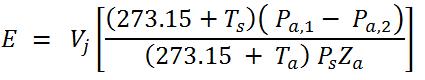
Where:
- Es
- Natural gas venting volumetric emissions from blowdown of equipment system (Sm3).
- Vj
- Total physical volume of blowdown equipment chambers (including, but not limited to, pipes, compressors and vessels) between isolation valves for the equipment system (m3).
- Ts
- Temperature at standard conditions (°C).
- Ta
- Temperature at actual conditions in the equipment system (°C).
- Ps
- Absolute pressure at standard conditions (kPa).
- Pa,1
- Absolute pressure at actual conditions in the equipment system (kPa) prior to depressurization.
- Pa,2
- Absolute pressure at actual conditions in the equipment system after depressurization; 0 if equipment is purged using non-GHG gases (kPa).
- Za
- Compressibility factor at actual conditions for natural gas. Use a default compressibility factor of 1, or a site-specific compressibility factor based on actual temperature and pressure conditions.
- Calculate both CH4 and CO2 volumetric and mass emissions from volumetric natural gas emissions using calculations in paragraphs (a)(13) and (a)(14) of this section.
- Blowdowns that are directed to flares use the Flare stacks calculation method under (a)(7) rather than the Blowdown vent stacks calculation method under this paragraph.
- Damage Events: A person required to report pursuant to this quantification method shall calculate fugitive emissions from damage events as follows:
- For Transmission (ON.350) systems only. Use company gas release data used for regulatory purposes if available. If this data is not available, then for each dig-in incident (i.e., line hit) which results in gas release ≥ 1.416 Sm3, calculate volumetric flow rate prior to pipeline isolation for both catastrophic pipeline ruptures and pipeline puncture incidents using the appropriate methodology below.
For catastrophic pipeline ruptures where the pipeline is severed use the following methodology:
Equation 350-8:
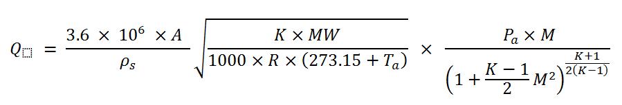
Equation 350-9:
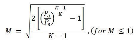
M = 1, (for all other cases)
Where:
- For Transmission (ON.350) systems only. Use company gas release data used for regulatory purposes if available. If this data is not available, then for each dig-in incident (i.e., line hit) which results in gas release ≥ 1.416 Sm3, calculate volumetric flow rate prior to pipeline isolation for both catastrophic pipeline ruptures and pipeline puncture incidents using the appropriate methodology below.
- Q
- natural gas venting volumetric flow rate (Sm3/h)
- A
- cross-sectional flow area of the pipe (m2, A = πD2⁄4,000,000)
- D
- inside diameter of the pipe (mm)
- K
- specific heat ratio of the gas (dimensionless – 1.299 for methane)
- M
- Mach number of the flow
- MW
- molecular weight of the gas (kg/mole, 16.043 kg/mole for methane)
- Pe
- pressure at the damage point (local atmospheric pressure, kPa)
- Pa
- pressure inside the pipe at supply (kPa) (usually taken at the point where the damaged main branches off a larger main). The supply pressure values should represent a stable supply pressure; however, it is important to account for the lower pressure which will occur because of the flow of gas from the break.
- R
- universal gas constant (8.3145 kPam3/kmol/K)
- Ta
- temperature inside pipe at the supply (°C)
- ρs
- gas density at standard conditions (kg/m3) (0.6785 kg/m3 for CH4)
For pipeline punctures where (PAtm⁄Pa) ≥ (PAtm⁄Pa)choked, use the following methodology, either individually per puncture, or in aggregate (using weighted averages) for multiple punctures of pipes of a given pressure and pipe type.
Equation 350-10:
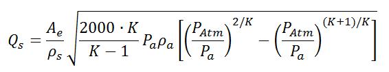
And:
Equation 350-11:
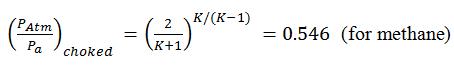
Where:
- Qs
- natural gas venting volumetric flow rate (Sm3/h)
- Ae
- size of the hole in the pipe (as either measured or estimated using engineering estimation techniques) (m2)
- ρs
- gas density at standard conditions (kg/m3) (0.6785 kg/m3 for CH4)
- K
- specific heat ratio of the gas (dimensionless – 1.299 for methane)
- Pa
- pressure inside the pipe (as either measured or estimated using engineering estimation techniques) at the puncture location (kPa)
- ρa
- gas density inside the pipe at the puncture location (kg/m3)
- PAtm
- atmospheric pressure outside the pipe (kPa)
- MW
- molecular weight of the natural gas (16.043 for methane)
- (PAtm/Pa)choked
- 0.546 - upper limit for choked flow
- For pipeline punctures where (PAtm/Pa) < (PAtm/Pa)choked, the person shall use the equations in section 6(i)(A) above, with the value of A being set to the size of the hole rather than the cross-sectional flow area of the pipe.
- Calculate volumetric natural gas emissions by multiplying Q or Qs for each pipeline rupture and puncture by the total elapsed time from pipeline rupture or puncture until isolation and final bleed-down to atmospheric pressure.
- Calculate both CH4 and CO2 mass emissions from volumetric natural gas emissions using the calculation in paragraphs (a)(13) and (a)(14) of this section.
- For Distribution systems only: Use emission factors and quantification methods in the CEPEI Methodology Manual.
- Flare stacks. A person required to report pursuant to this quantification method shall calculate CO2, CH4, and N2O emissions from a flare stack as follows:
- If there is a continuous flow measurement device on the flare, measured flow volumes can be used to calculate the flare gas emissions. If all of the flare gas is not measured by the existing flow measurement device, then the flow not measured can be estimated using engineering calculations based on best available data or company records. If there is not a continuous flow measurement device on the flare, a flow measuring device can be installed on the flare or use engineering calculations based on process knowledge, company records, and best available data.
- If there is a continuous gas composition analyzer on the gas stream to the flare, these compositions shall be used in calculating emissions. If there is no continuous gas composition analyzer on the gas stream to the flare, use the gas compositions for each stream of hydrocarbons going to the flare.
- Determine flare combustion efficiency from manufacturer. If not available, assume that flare combustion efficiency is 98 percent.
Calculate GHG volumetric emissions at actual conditions using Equations 350-12, 350-13, 350-14, and 350-15 of this section.
Equation 350-12:
Es,CH4(noncombusted) = Qs × (1 - η) × YCH4Equation 350-13:
Es,CO2(noncombusted) = Qs × YCO2Equation 350-14:
Es,CO2(combusted) = ∑iη × Qs × Yi × niEquation 350-15:
Es,CO2(total) = Es,CO2(combusted) + Es,CO2(noncombusted)Where:
- Es,CH4(noncombusted)
- Contribution of annual noncombusted volumetric CH4 emissions from flare stack (Sm3).
- Es,CO2(noncombusted)
- Contribution of annual volumetric CO2 emissions from CO2 in the inlet gas passing through the flare noncombusted (Sm3).
- Es,CO2(combusted)
- Contribution of annual volumetric CO2 emissions from combustion from flare stack (Sm3).
- Qs
- Volume of natural gas sent to flare during the year (Sm3).
- η
- Fraction of natural gas combusted by flare (default combustion efficiency is 0.98). For gas sent to an unlit flare, η is zero.
- YCH4
- Mole fraction of CH4 in gas to the flare.
- YCO2
- Mole fraction of CO2 in gas to the flare.
- Yi
- Mole fraction of hydrocarbon constituents i (i.e., methane, ethane, propane, butane, pentanes,hexane, and pentane plus) in natural gas to the flare.
- ni
- Number of carbon atoms in the hydrocarbon constituent i; (e.g., 1 for methane, 2 for ethane, 3 for propane, 4 for butane, 5 for pentanes, 6 for hexanes and 7 for pentanes plus) in natural gas to the flare.
- Calculate both CH4 and CO2 mass emissions from volumetric CH4 and CO2 emissions as determined in paragraph (7)(iv) of this section using the calculation in paragraph (a)(14) of this section.
Calculate N2O emissions using Equation 350-16:
Equation 350-16:
EN20 = Qs × HHV × EF × 0.001
Where:
- EN20
- Annual N2O mass emissions from flaring (tonnes/year).
- Qs
- Volume of gas combusted by the flare in the reporting period (Sm3/yr).
- HHV
- High heat value of the flared gas from paragraph (7)(ii)
- EF
- N2O emission factor. Use 9.52 × 10⁻⁵ kg N2O/GJ.
- 0.001
- Conversion factor from kilograms to tonnes.
- To avoid double-counting, this emissions source excludes any emissions calculated under other emissions sources in this section. Where gas to be flared is manifolded from multiple sources in ON.353 to a common flare, report all flaring emissions under ON.355(a)(7).
Centrifugal compressor venting. A person required to report pursuant to this quantification method shall calculate emissions from all centrifugal compressor vents as follows. Where venting emissions are sent to a common flare, calculate emissions using ON.353(a)(7).
Dry seal and wet seal centrifugal compressors can enter the following operating modes: “operating, pressurized”, “stand-by, pressurized” or “not-operating, depressurized”.
- The person shall calculate CO2, and CH4, and N2O (when flared) emissions from both wet seal and dry seal centrifugal compressor vents (including wet seal oil degassing vent lines, but excluding dry deal gas vent lines) for all compressors using a temporary or permanent flow measurement meter such as, but not limited to, portable utility grade meter (bellows meter), high-flow sampler or vane anemometer according to methods set forth in ON.354(a(2) and (4).
Estimate annual emissions using flow meter measurement using Equation 350-17 of this section.
Equation 350-17:
Es,i = ∑mQs,m × tm × Yi × (1 − CF)Where:
- Es,i
- Annual GHG i (either CH4 or CO2) volumetric emissions from all compressor venting modes (Sm3).
- Qs,m
- Measured volumetric gas emissions during operating mode m described in paragraph (8)(v) of this section (Sm3/h).
- tm
- Total time the compressor is in operational mode m during the calendar year (h)
- Yi
- Annual average mole fraction of GHG i in the degassing vent gas; use the appropriate gas compositions in paragraph (13)(ii) of this section.
- CF
- Fraction of centrifugal compressor vent gas sent to vapour recovery or fuel gas or other beneficial use as determined by keeping logs of vent gas that is directed to the fuel gas system.
- m
- The operational mode of a centrifugal compressor.
To ensure that emissions for modes not found during the annual measurement are included in reported estimates, Equation 350-17a shall be used to calculate total emissions
Equation 350-17a:
Es,i,c = Es,i + Em,nfWhere:
- Es,i,c
- Total estimate of emissions from all operating modes
- Es,i
- Output of Equation 350-17
- Em,nf
- Estimate of emissions for the modes not found during the annual measurement as calculated from emissions for mode not found for the compressor during previous years and prorated for the time in the year for the mode not found. If the mode not found did not occur in previous years, estimates from a similar compressor or manufacturer emission factors may be used, in order of preference.
- An engineering estimate approach based on similar equipment specifications and operating conditions may be used to determine the Qs,m variable in place of actual measured values for centrifugal compressors that are operated for no more than 200 hours in a calendar year in place of metered gas volumes if an applicable meter is not present on the compressor. Alternatively, a source-specific emissions factor can be established by measuring the emissions from relevant sources during each operational mode.
- Conduct an annual measurement for each compressor in the mode in which it is found (see below) during the annual measurement starting in the year 2018. By the start of the 2018 calendar year (January 1, 2018), each compressor shall be measured at least once. As applicable, measure emissions from (including emissions manifolded to common vents) degassing vents, unit isolation-valve vents and blowdown-valve vents. If there is a safety risk that cannot be (reasonably) mitigated with measuring emissions from a specific vent line, the person may use an emission factor approach instead. Winter safety is not a valid safety risk unless the site can only be accessed during the winter. The operational modes are:
- Operating pressurized mode, blowdown vent leakage through the blowdown vent stack and wet seal oil degassing vent (if applicable); for wet seal and dry seal compressors.
- Standby pressurized mode.
Not operating, depressurized mode, unit isolation-valve leakage through the blowdown vent stack.
(C.1) Not withstanding paragraph (v) above, for the not operating, depressurized mode, each compressor shall be measured at least once in any three consecutive calendar years if this mode is not found in the annual measurement (if the compressor enters the not operating depressurized mode during normal service (i.e. excluding maintenance).
(C.2) A compressor is exempt from this requirement to measure in the not operating, depressurized mode if,
- During normal service, it remains pressurized and the only time the unit is depressurized is for maintenance or as a result of an emergency shutdown; or
- The compressor has blind flanges in place.
(C.3) If a compressor unit is exempt from the 3 year measurement requirement in C.1, use Equation 350-17a to calculate emissions for that unit for the not-operating depressurized mode.
- Calculate both CH4 and CO2 mass emissions from volumetric CH4 and CO2 emissions as determined in paragraphs (8)(i) through (iv) of this section using calculations in paragraph (a)(14) of this section.
- Calculate emissions from degassing vent vapours to flares as follows:
- Use the degassing vent vapour volume and gas composition as determined in paragraphs (8)(i) through (iv) of this section.
- Use the calculation methodology of flare stacks in paragraph (7) of this section to determine degassing vent vapour emissions from the flare.
- Emissions from centrifugal compressor dry seal gas vent lines may be determined following the procedures set forth in paragraphs (a)(5) and (a)(7), engineering estimates or other industry standard method, as appropriate.
Reciprocating compressor venting. A person required to report pursuant to this quantification method shall calculate annual CH4 and CO2 emissions from all reciprocating compressor vents as follows.
Where venting emissions are sent to a common flare, calculate emissions using ON.353(7).
A reciprocating compressor’s operational modes include “operating, pressurized”, “standby, pressurized mode” and “not operating, depressurized
Calculate annual emissions using the flow measurement in (9)(iii) or (iv) below and Equation 350-18:
Equation 350-18:
Es,i = ∑mQs,m × tm × Yi(1 − CF)
Where:
- Es,i
- Annual volumetric emissions of GHG i (either CH4 or CO2) from all compressor venting modes (Sm3/yr).
- Qs,m
- Measured volumetric gas emissions during operating mode m described in paragraph (9)(v) (Sm3/h).
- tm
- Total time the compressor is in operational mode m during the calendar year (h).
- Yi
- Annual average mole fraction of GHG i in the vent gas; use the appropriate gas compositions in paragraph (13)(ii) of this section.
- CF
- Fraction of reciprocating compressor vent gas sent to vapour recovery or fuel gas or other beneficial use as determined by keeping logs of the vent gas that is directed to the fuel gas system.
- m
- The operational mode of a reciprocating compressor.
Calculate total emissions, including modes not found during the annual measurement, using Equation 350-18a:
Equation 350-18a:
Es,i,c = Es,i + Em,nf
Where:
- Es,i,c
- Total estimate of emissions from all operating modes
- Es,i
- Output of Equation 350-18
- Em,nf
- Estimate of emissions for the modes not found during the annual measurement as calculated from emissions for operational mode not found for the compressor during previous years and prorated for the time in the year for the mode not found. If the operational mode not found did not occur in previous years, estimates from a similar compressor or manufacturer emission factors may be used.
- If the reciprocating rod packing and blowdown vent is connected to an open-ended vent line then use one of the following two methods to calculate emissions.
- Measure emissions from all vents (including emissions manifolded to common vents) including rod packing, unit isolation valves, and blowdown vents using either calibrated bagging or High-flow Sampler according to methods set forth in ON.354(a)(3) and (4).
- Use a temporary meter such as a portable utility grade meter (bellows meter) a vane anemometer or a permanent meter such as an orifice meter to measure emissions from all vents (including emissions manifolded to a common vent) including rod packing vents, unit isolation valves, and blowdown valves according to methods set forth in ON.354(a)(2). If you do not have a permanent flow meter, you may install a temporary meter or a permanent flow meter on the vents. For through-valve leakage to open-ended vents, such as unit isolation valves on not-operating, depressurized compressors and blowdown valves on pressurized compressors, you may use an acoustic detection device according to methods set forth in ON.354(a).
- If the rod packing case is not equipped with a vent line, use the following method to estimate emissions:
- Use the methods described in ON.354(a)(1) to conduct a progressive leak detection of fugitive equipment leaks from the packing case into an open distance piece, or from the compressor crank case breather cap or vent with a closed distance piece.
- Measure emissions using a High-flow Sampler, or calibrated bag, or appropriate meter according to methods set forth in ON.354(a)(2), (3), or (4).
Conduct an annual measurement for each compressor in the operational mode in which it is found during the annual measurement starting in 2018. Measure emissions from (including emissions manifolded to common vents) reciprocating rod-packing vents, unit isolation-valve vents, and blowdown-valve vents. If there is a safety risk that cannot be reasonably mitigated with measuring emissions from a specific vent line, the Person may use an emission factor approach instead. Given that there is not a requirement to measure in the winter months, winter safety is not an applicable safety risk unless the site is only accessible in the winter.
The operational modes are:
- Operating pressurized mode, blowdown vent leakage through the blowdown vent stack and reciprocating rod packing emissions.
- Standby pressurized mode.
Not operating, depressurized mode, unit isolation-valve leakage through the blowdown vent stack.
(C.1) Not withstanding paragraph (v) above, for the not operating, depressurized mode, each compressor shall be measured at least once in any three consecutive calendar years if this mode is not found in the annual measurement (if the compressor enters the not operating depressurized mode during normal service (i.e. excluding maintenance)).
(C.2) A compressor is exempt from this requirement to measure in the not operating, depressurized mode if,
- During normal service, it remains pressurized and the only time the unit is depressurized is for maintenance or as a result of an emergency shutdown; or
- The compressor has blind flanges in place.
(C.3) If a compressor unit is exempt from the 3 year measurement requirement identified in the first paragraph, use Equation 350-18a in paragraph (9)(ii) to calculate emissions for that unit for the not-operating depressurized mode.
- Estimate CH4 and CO2 volumetric and mass emissions from volumetric natural gas emissions using the calculations in paragraphs (a)(13) and (a)(14) of this section.
- Adjust the emissions from reciprocating compressor vent vapors as follows if they are sent to a vapor recovery system.
- Adjust the emissions estimated in paragraphs (9)(i) of this section for the emissions recovered using a vapor recovery system as determined by using engineering estimate based on best available data, equipment or design specifications, manufacturer’s data, operating data.
- An engineering estimate approach based on similar equipment specifications and operating conditions or manufacturer’s data may be used to determine the Qs,m variable in place of actual measured values for reciprocating compressors that are operated for no more than 200 hours in a calendar year.
Leak detection and leaker emission factors. A person required to report pursuant to this calculation method shall use sampling methods (described in ON.354(a)) to conduct a leak detection survey of fugitive equipment leaks from all sources listed in ON.352(b)(2), (c)(2), (d)(2), (e)(2) where total emissions for the station are 10,000 tonnes CO2e or greater. If the total emissions from the station is less than 10,000 tonnes CO2e, the person may use this calculation method or the calculation method in ON.353(a)(11).
The calculation in paragraph (10) applies to emissions sources in streams with gas containing greater than 10 percent CH4 plus CO2 by weight. Emissions sources in streams with gas containing less than 10 percent CH4 plus CO2 by weight need to be reported instead under paragraph (l) of this section.
If fugitive equipment leaks are detected for sources listed in this paragraph, calculate equipment leak emissions per source using Equation 350-19 (for volumetric emission factor [Sm3/h/component]) or Equation 350-20 (for mass emission factors [t/h/component]) of this section, as appropriate, for each source with fugitive equipment leaks.
Equation 350-19:
Ei = EFs × Yi × t × ρs,i × 0.001Equation 350-20:
Es,j = EFs × Yi × tWhere:
- Es,i or Es,j
- Annual total mass emissions of GHGi (CH4 or CO2) from each fugitive equipment leak source (tonnes/year).
- EFs
- Leaker emission factor for specific sources listed in Table 350-1 through Table 350-5 of this section or facility/company-specific emission factors* used in place of Tables 350-1 to 350-5 (Sm3/component/year for Equation 350-19 and tonnes/component/year for Equation 350-20).
- Yi
- For volumetric emissions in Equation 350-19, use 0.975 for CH4 for natural gas transmission, compression and underground natural gas storage and 1.1 × 10⁻² for CO2; for LNG storage and LNG import and export equipment, Yi equals 1 for CH4 and 0 for CO2; or use the experimentally determined gas composition for CO2 and CH4. For mass emissions in Equation 350-20, use mass fractions of CH4 and CO2 from each unit of a distribution or transmission company within a jurisdiction that has similar gas composition or the CEPEI Methodology Manual.
- t
- Total time the component was found leaking and operational, in hours. If one leak detection survey is conducted, assume the component was leaking from the start of the year or the date of the last survey until the leak was repaired and then zero for the remainder of the interval between leak surveys. If the leak was not repaired, assume the component was leaking for the entire year or the entire leak survey interval. If multiple leak detection surveys are conducted, assume that the component found to be leaking has been leaking since the last survey during which it was determined to be not leaking, or the beginning of the calendar year. For the last leak detection survey in the calendar year or leak survey interval, assume that all leaking components continue to leak until the end of the calendar year or leak survey interval and until the component was repaired and then zero until the end of the year or leak survey interval.
- ρs,i
- Density of GHG i (1.861 kg/m3 for CO2 and 0.678 kg/m3 for CH4 at standard conditions of 15 °C and 1 atmosphere).
- 0.001
- Conversion factor from kilograms to tonnes.
- Onshore natural gas transmission compression stations shall use the appropriate default leaker emission factors listed in Table 350-1 of this section for fugitive equipment leaks detected from connectors, valves, pressure relief valves, meters, and open ended lines.
- Underground natural gas storage stations shall use the appropriate default leaker emission factors listed in Table 350-2 of this section for fugitive equipment leaks detected from connectors, valves, pressure relief valves, meters, and open-ended lines.
- LNG storage stations shall use the appropriate default leaker emission factors listed in Table 350-3 of this section for fugitive equipment leaks detected from valves, pump seals, connectors, and other equipment.
- LNG import and export stations shall use the appropriate default leaker emission factors listed in Table 350-4 of this section for fugitive equipment leaks detected from valves; pump seals; connectors; and other.
Population count and emission factors. A person required to report pursuant to this quantification method shall use the following calculation for stations with total emissions that are less than 10,000 tonnes per year, for sources listed in ON.352 (b)(2), (b)(6), (c)(2), (d)(2), (e)(2), (f)(1), f(2), f(3) and (f)(4) on streams with gas containing greater than 10 percent CH4 plus CO2 by weight.
Emissions sources in streams with gas containing less than 10 percent CH4 plus CO2 by weight do not need to be reported. In addition, emission sources at which a leak detection has been conducted and reported under ON.353(a)(10) (either voluntarily or required under Section 353(a)(10)) are exempt from the following requirements.
Calculate emissions from all sources listed in this paragraph using Equation 350-21 (for volumetric emission factor [m3/h/component]) or Equation 350-22 (for mass emission factors [kg/h/component]) of this section, as appropriate.
Equation 350-21:
Ei = N × EFs × Yi × t × ps,i × 0.001Equation 350-22:
Ei = N × EFs × Xi × t × 0.001Where:
- Ei
- Annual total mass emissions of GHG i (CH4 or CO2) from each fugitive source (tonnes/year).
- N
- Total number of this type of emission source at the station. The average component counts by major equipment pieces from the CEPEI Methodology Manual, other relevant Canadian Gas Association (CGA), or Canadian Association of Petroleum Producers documentation, may be used for 2017 and 2018 calendar year emissions as appropriate for operations and required by (i) through (v), below. For 2019 calendar year emissions and onwards component counts for individual facilities is to be used except for sources listed in ON.352 (f)(1). If station or company-specific major equipment count data that meet or exceed the quality of the relevant default count data are available, they shall be used in its place. Current processing and instrumentation drawings (P&ID) may be used for the source of component (or major equipment) counts for all years. For sources listed in ON.352 (f)(1), the average component counts used in 2017 and 2018 may also be used for 2019 onwards.
- EFs
- Population emission factor for specific sources listed in Table 350-1 through Table 350-5 of this section (Sm3/component/hour for Equation 350-21 and tonnes/component/hour for Equation 350-22). Direction on the use of Tables 350-1 through 350-5, provided prior to the tables, shall be followed and indicates that if facility specific emission factors are available these facility specific emission factors shall be used**.
- Yi
- For volumetric emissions in Equation 350-21, use 0.975 for CH4 for natural gas transmission, compression and underground natural gas storage and 1.1 × 10⁻² for CO2; for LNG storage and LNG import and export equipment, Yi equals 1 for CH4 and 0 for CO2; and for natural gas distribution, Yi equals 1 for CH4 and 1.1 × 10⁻² for CO2 or use the experimentally determined gas composition for CO2 and CH4.
- Xi
- For mass emissions in Equation 350-22, use mass fractions of CH4 and CO2 from operation/facility-specific data or the 2012 CEPEI methodology manual.
- t
- Total time the specific source associated with the fugitive equipment leak was operational in the calendar year (hours).
- ps,i
- Density of GHG i (1.861 kg/m3 for CO2 and 0.678 kg/m3 for CH4 at standard conditions of 15 °C and 1 atmosphere).
- 0.001
- Conversion factor from kilograms to tonnes.
- Transmission stations shall use the appropriate default population emission factors listed in Table 350-1 of this section for fugitive equipment leaks from connectors, valves, pressure relief valves, and open-ended lines.
- Underground natural gas storage stations shall use the appropriate default population emission factors listed in Table 350-2 of this section for fugitive equipment leaks from connectors, valves, pressure relief valves, and open-ended lines.
- LNG storage stations shall use the appropriate default population emission factors listed in Table 350-3 of this section for fugitive equipment leaks from vapour recovery compressors.(except storage at LNG import and export facilities which is covered in ON.353(a)(11)(iv)).
- LNG import and export stations shall use the appropriate default population emission factor listed in Table 350-4 of this section for fugitive equipment leaks from vapour recovery compressors.
- Natural gas distribution facilities shall use the appropriate emission factors as follows.
- Below grade metering-regulating stations; distribution mains; and distribution services, shall use the appropriate default population emission factors listed in Table 350-5 of this section.
- Above grade meter-regulating stations and all other above-grade stations including customer meters shall be estimated using the CEPEI Methodology Manual methods and component emission factors.
- For buried pipeline-main and service line leaks, Equations 350-21 and 350-22 and their inputs may be modified as outlined in the CEPEI Methodology Manual.
- Volumetric emissions. A person required to report pursuant to this quantification method shall calculate volumetric emissions at standard conditions as specified in paragraphs (12)(i) or (12)(ii), with actual pressure and temperature of this section determined by engineering estimate based on best available data unless otherwise specified.
Calculate natural gas volumetric emissions at standard conditions by converting actual temperature and pressure to standard temperature and pressure (15 °C and 1 atmosphere) using Equation 350-23 of this section.
Equation 350-23:

Where:
- Es
- Natural gas volumetric emissions at standard temperature and pressure (STP) conditions (Sm3).
- Ea
- Natural gas volumetric emissions at actual conditions (m3).
- Ts
- Temperature at standard conditions (15 °C).
- Ta
- Temperature at actual emission conditions (°C).
- Ps
- Absolute pressure at standard conditions (101.325 kPa).
- Pa
- Absolute pressure at actual conditions (kPa).
Calculate GHG volumetric emissions at standard conditions by converting actual temperature and pressure of GHG emissions to standard temperature and pressure using Equation 350-24 this section.
Equation 350-24:

Where:
- Es,i
- GHGi volumetric emissions at standard temperature and pressure (STP) conditions (Sm3).
- Ea,i
- GHGi volumetric emissions at actual conditions (m3).
- Ts
- Temperature at standard conditions. (15°C).
- Ta
- Temperature at actual emission conditions. (°C).
- Ps
- Absolute pressure at standard conditions (101.325 kPa).
- Pa
- Absolute pressure at actual conditions (kPa).
GHG volumetric emissions. A person required to report pursuant to this quantification method shall calculate the volumetric emission using the following calculations.
If the GHG volumetric emissions at actual conditions are known, follow the method in paragraph (13)(ii) to calculate their emissions at standard conditions.
If the GHG volumetric emissions are not yet known, use engineering estimate based on best available data unless otherwise specified and the methods below to calculate GHG volumetric emissions at standard conditions as specified in paragraphs (13)(i) and (ii) of this section determined by.
Estimate CH4 and CO2 emissions from natural gas emissions using Equation 350-25 of this section
Equation 350-25:
Es,i = Es × YiWhere:
- Es,i
- GHG i (either CH4 or CO2) volumetric emissions at standard conditions.
- Es
- Natural gas volumetric emissions at standard conditions.
- Yi
- Mole fraction of GHG i in the natural gas.
- For Equation 350-25 of this section, the mole fraction, Yi, shall be the annual average mole fraction for each unit of a natural gas distribution, natural gas transmission, LNG storage, LNG import or export, or underground natural gas storage company within a jurisdiction that has similar gas composition as sampled within the current (required if available) or previous (if current data not available) reporting period, using the methods set forth in ON.354(a(2)), and specified in paragraphs below.
- GHG mole fraction in transmission pipeline natural gas that passes through the facility for onshore natural gas transmission compression facilities.
- GHG mole fraction in natural gas stored in underground natural gas storage facilities.
- GHG mole fraction in natural gas stored in LNG storage facilities.
- GHG mole fraction in natural gas stored in LNG import and export facilities.
- GHG mole fraction in local distribution pipeline natural gas that passes through the facility for natural gas distribution facilities.
GHG mass emissions. A person required to report pursuant to this quantification method shall Calculate GHG mass emissions in tonnes of carbon dioxide equivalent by converting the GHG volumetric emissions at standard conditions into mass emissions using Equation 350-26 of this section.
Equation 350-26:
Ei = Es,i × ρs,i × 0.001Where:
- Ei
- GHG i (either CH4, CO2, or N20) mass emissions (tonnes CO2e).
- Es,i
- GHG i (either CH4, CO2 or N2O) volumetric emissions at standard conditions (Sm3).
- ρs,i
- Density of GHG i (1.861 kg/m3 for CO2 and 0.678 kg/m3 for CH4 at standard conditions of TS = 15°C and PS = 101.325 kPa).

- MWi
- Molecular weight for GHGi (kg/kmole).
- Ru
- Universal gas constant (8.31434 kJ/kmole K)
- 0.001
- Conversion factor from kilograms to tonnes
- Other venting or fugitive emissions. A person required to report pursuant to this quantification method shall determine all venting or fugitive emissions not covered by quantification methods in ON.353 using methodologies consistent with those presented in the CEPEI Methodology Manual, or in other relevant documents published by the Canadian Gas Association or any other industry association.
Transmission storage tanks. A person required to report pursuant to this quantification method shall by 2019 determine emissions from transmissions storage tanks using the following.
For condensate storage tanks, either water or hydrocarbon, without vapour recovery or thermal control devices in onshore natural gas transmission compression facilities the operator shall calculate CH4, CO2 and N2O (when flared) annual emissions from compressor scrubber dump valve leakage as follows.
- Monitor the tank vapour vent stack annually for emissions using an optical gas imaging instrument according to methods set forth in ON.354(a)(1) or by directly measuring the tank vent using a flow meter, calibrated bag, or High-flow Sampler according to methods in ON.354(a)(2) through (4) for a duration of 5 minutes. Or the person may annually monitor leakage through compressor scrubber dump valve(s) into the tank using an acoustic leak detection device according to methods set forth in ON.354(a)(1)(D).
- If the tank vapours are continuous for 5 minutes, or the acoustic leak detection device detects a leak, then use one of the following two methods.
- Use a meter, such as a turbine meter, calibrated bag, or High-flow Sampler to estimate tank vapour volumes according to methods set forth in ON.354(a)(2) through (4). If the vent is directly measured for five minutes under paragraph (16)(1) of this section to detect continuous leakage, this serves as the measurement.
- Use an acoustic leak detection device on each scrubber dump valve connected to the tank according to the method set forth in ON.354(a).
- Use the appropriate gas composition in paragraph (13) of this section.
- If the leaking dump valve(s) is fixed following leak detection, the annual emissions shall be calculated from the beginning of the calendar year to the time the valve(s) is repaired. If the leak is not repaired, assume the dump valve is leaking for the entire year or until the dump valve is repaired.
- Calculate annual emissions from storage tanks to flares as follows:
- Use the storage tank emissions volume and gas composition as determined in paragraphs (13)(i) through (13)(iii) of this section.
- Use the calculation methodology of flare stacks in paragraph (7) of this section to determine storage tank emissions sent to a flare.
ON.354 Sampling, Analysis, and Measurement Requirements
- A person required to report pursuant to this quantification method shall ensure instruments used for sampling, analysis and measurement shall be operated and calibrated according to regulatory, manufacturer’s, or other written specifications or requirements. All sampling, analysis and measurement shall be conducted only by, or under the direct supervision of personnel or individuals with demonstrated understanding and experience in the application (and principles related) of the specific sampling, analysis and measurement technique in use.
- A person required to report pursuant to this quantification method shall undertake the following Leak Detection program
- If a documented leak detection or integrity management standard or requirement that is required by Ontario or federal legislation or regulation (e.g.,. CSA Z662-07 Oil & Gas Pipeline Systems) or by a standard or method from Canadian Gas Association, the documented standard or requirement shall be followed – including service schedules for different components and/or facilities - with reporting as required for input to the calculation methods herein. A maximum of 36 months is allowed between leak detection surveys.
If there is no such legal requirement (as specified in the previous paragraph), then representative sampling is required using one of the methods outlined below in combination with best industry practices for use of the method– including service schedules for different components - to determine the count of leaks (and time leaking) required in ON.353 (a)(10), as applicable. Representative sampling means establishing the most valid or credible sample of leaks that accurately characterizes the number of fugitive equipment leaks required per sample interval, under operating conditions. A baseline representative sample of leaks shall be established under normal operating conditions for the 2017 calendar years or upon acquisition of previously operated equipment or within the first year of operation of newly constructed or acquired equipment. Subsequent representative sampling shall be based on random or stratified sampling, modeling, detection or measurement of leaks under normal operating conditions. After establishing the baseline representative sample of leaks per sample interval, a maximum of 36 months is allowed between sampling. The interval is determined based on whether there are leaks. If a leak is found and immediately repaired, the existing schedule may be maintained. If a leak is found and not repaired the maximum interval between sampling is 18 months and the leak shall be monitored (and optionally measured) on a regular basis until repaired. If the equipment is replaced the maximum sampling interval is 18 months until a baseline representative sample of leaks has been established under normal operating conditions.
Leak detection for fugitive equipment leaks shall be performed for all identified equipment in operation or on standby mode using one of the following.
Optical gas imaging instrument. Use an optical gas imaging instrument for fugitive equipment leaks detection in accordance with 40 CFR part 60, subpart A, §60.18(i)(1) and (2) Alternative work practice for monitoring equipment leaks. In addition, the optical gas imaging instrument shall be operated to image the source types required by this proposed reporting rule in accordance with the instrument manufacturer’s operating parameters. The optical gas imaging instrument shall comply with the following requirements:
(A.1) Provide the person with an image of the potential leak points for each piece of equipment at both the detection sensitivity level and within the distance used in the daily instrument inspection described in the relevant best practices. The detection sensitivity level depends upon the frequency at which leak monitoring is to be performed.
(A.2) Provide a date and time stamp for video records of every monitoring event.
- Bubble tests. Uses soap or other types of bubbles on equipment to visually detect the leak of gases from the equipment.
- Portable organic vapour analyzer. Use a portable organic vapour analyzer in accordance with US EPA Method 21 or as outlined in standard Canadian Gas Association methodologies or the CAPP Best Management Practices for Fugitive Emissions
- Other methods as outlined in standard Canadian Gas Association methodologies or the CAPP Best Management Practices for Fugitive Emissions (as amended from time to time) may be used as necessary for operational circumstances. Other methods based on an engineering assessment may also be used as necessary for operational circumstances provided there is documentation on the method used, results of tests, and the method’s reliability and accuracy is maintained and updated at regular intervals.
- All flow meters, composition analyzers and pressure gauges that are used to provide data for the GHG emissions calculations shall use appropriate QA/QC procedures, including measurement methods, maintenance practices, and calibration methods by 2018 and in each subsequent calendar year according to an appropriate standard published by a consensus standards organization. If a consensus based standard is not available, industry standard practices such as manufacturer instructions shall be used.
- Use calibrated bags (also known as vent bags) only where the emissions are at or near atmospheric pressures and hydrogen sulphide levels are such that it is safe to handle and can capture all the emissions, below the maximum temperature specified by the vent bag manufacturer, and the entire emissions volume can be encompassed for measurement.
- Hold the bag in place enclosing the emissions source to capture the entire emissions and record the time required for completely filling the bag. If the bag inflates in less than one second, assume one second inflation time.
- Perform three measurements of the time required to fill the bag, report the emissions as the average of the three readings.
- Correct the natural gas volumetric emissions to standard conditions using the calculations in ON.353(a)(12).
- Estimate CH4 and CO2 volumetric and mass emissions from volumetric natural gas emissions using the calculations in ON.353(a)(13) and (14).
- Use a high-flow sampler to measure emissions within the capacity of the instrument.
- Calibrate the instrument at 2.5 percent methane with 97.5 percent air and 100 percent CH4 by using calibrated gas samples and by following manufacturer’s instructions for calibration.
- Conduct measurements, using equipment manufacturer operating procedures and relevant measurement methodologies, by positioning the instrument for complete capture of the fugitive equipment leaks without creating backpressure on the source.
- If the High-flow Sampler, along with all attachments available from the manufacturer, is not able to capture all the emissions from the source then you shall use anti-static wraps or other aids to capture all emissions without violating operating requirements as provided in the instrument manufacturer’s manual.
- Estimate CH4 and CO2 volumetric and mass emissions from volumetric natural gas emissions using the calculations in ON.353(a)(13) and (14).
- A person required to report pursuant to this quantification method shall undertake the following Leak Detection program
ON.355 Procedures for Estimating Missing Data
- A person required to report pursuant to this quantification method shall retain a complete record of all estimated and/or measured parameters used in the GHG emissions calculations.
- If data are lost or an error occurs during annual emissions estimation or measurements, the estimation or measurement activity for those sources shall be repeated as soon as possible, including in the subsequent calendar year if missing data are not discovered until after December 31 of the calendar year, until valid data for reporting is obtained.
- Data developed and/or collected in a subsequent calendar year to substitute for missing data cannot be used for that subsequent year’s emissions estimation.
- Where missing data procedures are used for the previous year, at least 30 days shall separate emissions estimation or measurements for the previous year and emissions estimation or measurements for the current year of data collection.
- For missing data that are continuously monitored or measured (for example flow meters), or for missing temperature and pressure data, the person may use best available data for use in emissions determinations. The person shall record and report the basis for the best available data in these cases.
ON.356 Tables
Directions for the use of Tables 350-1 to 350-5:
- For each component listed in the Tables 350-1 to 350-5 or otherwise required by the quantification method referencing Tables 350-1 and 350-2:
- If statistically valid company specific emission factors for a component type are available they shall be used. If statistically valid company specific emission factors can be reasonably developed using existing company leak detection data then they shall be used.
- If company specific emissions factors for a component type are not available, a person shall use statistically valid company specific emission factors if they are available. If statistically valid company-specific emission factors can be reasonably developed using existing company leak detection data then they shall be used.
- If statistically valid facility or company-specific emission factors for a specific component are not available, emission factors in the default Tables 350-1 to 350-5 may be used,
- A person may use the default factors specified below, company specific emissions factors (if such emission factors are available).
- If an emission factor required by the quantification method referencing Tables 350-1 through 350-5 is not provided in the tables, emission factors from the CEPEI Methodology Manual or US EPA 40 CFR Part 98.230 Tables W-3 through W-7 (in order of preference), may be used (as converted for use in the relevant equation).
- Documentation on the method used to update the emission factors, input data, sampling methodology and other relevant information shall be kept by the person and provided to the jurisdiction or verifier upon request.
- Updated emission factors can only be incorporated for reporting purposes at the start of a reporting period and not during a calendar year.
- All emission factors or data collection for emission factors shall be developed using the CEPEI Methodology Manual, or other methods if the CEPEI Methodology Manual methods are not available or applicable. Company-specific emission factors that have been developed using existing company leak detection data shall be updated at a minimum on a three year cycle, with the first update to the original facility and company- specific emission factors for the 2020 reporting period, at the latest.
| All Components, Natural Gas Service | Population Emission Factor1a (tonnes/hour/component) | Leaker Emission Factor1b (tonnes/hour/component) |
|---|---|---|
| Connector | 4.471E-7 | 4.848E-5 |
| Block valve | 4.131E-6 | 1.275E-4 |
| Control valve | 1.650E-5 | 8.205E-5 |
| Station or pressurized compressor blowdown valve | 3.405E-3 | 5.691E-3 |
| Pressure relief valve | 1.620E-4 | 5.177E-4 |
| Orifice meter | 4.863E-5 | 2.076E-4 |
| Other flow meter | 9.942E-9 | 3.493E-7 |
| Regulator | 7.945E-6 | 1.125E-4 |
| Open-ended line | 9.183E-5 | 1.580E-4 |
| Other Components, Natural Gas Service | Population Emission Factor (Sm3/hour/component)2 |
|---|---|
| Low-bleed pneumatic device vents | 3.88 E-2 |
| High continuous bleed pneumatic device vents | 2.605 E-1 |
| Intermittent high bleed pneumatic device vents | 2.476 E-1 |
| Intermittent low bleed pneumatic device vents | 6.65 E-2 |
| Diaphragm Pumps | 1.0542 E-0 |
| Piston Pumps | 5.917 E-1 |
1 Clearstone Engineering Ltd. Methodology Manual: Estimation of Air Emissions from the Canadian Natural Gas Transmission, Storage and Distribution System. Prepared for Canadian Energy Partnership for Environmental Innovation (CEPEI). 2012. As these emission factors are updated from time to time, the intention is to incorporate such updates here as well as permit use of the most recent values published.
- Table 9, p50 b.
- Table 12, p80.
2 Prasino Final Pneumatic Field Sampling Report or Direct conversion of EFs in 2011 EPA Subpart W Table W (scf to SM3). Source : US EPA, Mandatory Reporting of greenhouse Gases – Rules and Regulations, Subpart W Table 7, Dec 23, 2012.
| Underground Storage | Emission Factor (Sm3/hour/component) Prasino Final Pneumatic Field Sampling Report* Direct conversion of EFs in EPA Subpart W Table* W-4 (scf to Sm3) |
|---|---|
| Leaker Emission Factors - Storage Station, Gas Service -Valve1 | 4.268 E-1 |
| Leaker Emission Factors - Storage Station, Gas Service - Connector | 1.60 E-1 |
| Leaker Emission Factors - Storage Station, Gas Service - Open-ended line | 4.967 E-1 |
| Leaker Emission Factors - Storage Station, Gas Service - Pressure relief valve | 1.140 |
| Leaker Emission Factors - Storage Station, Gas Service - Meter | 5.560 E-1 |
| Population Emission Factors - Storage Wellheads, Gas Service - Connector | 2.8 E-4 |
| Population Emission Factors - Storage Wellheads, Gas Service - Valve | 2.8 E-3 |
| Population Emission Factors - Storage Wellheads, Gas Service - Pressure relief valve | 4.8 E-3 |
| Population Emission Factors - Storage Wellheads, Gas Service - Open-ended line | 8.5 E-4 |
| Population Emission Factors - Other Components, Gas Service - Low-bleed pneumatic device vents | 3.88 E-2 |
| Population Emission Factors - Other Components, Gas Service - High continuous bleed pneumatic device vents | 2.605 E-1 |
| Population Emission Factors - Other Components, Gas Service - Intermittent high bleed pneumatic device vents | 2.476 E-1 |
| Population Emission Factors - Other Components, Gas Service - Intermittent (low) bleed pneumatic device vents | 56.65 E-12 |
| Population Emission Factors - Other Components, Gas Service - Diaphragm Pumps | 1.0542 E-0 |
| Population Emission Factors - Other Components, Gas Service - Piston Pumps | 5.917 E-1 |
* Emission factors are conversions of those contained in the U.S. EPA Subpart W Table W-4.
1 Valves include control valves, block valves and regulator valves
| LNG Storage | Emission Factor (Sm3/hour/component) Direct conversion of EFs in EPA Subpart W Table W-5 (scf to Sm3) |
|---|---|
| Leaker Emission Factors - LNG Storage Components, LNG Service - Valve | 3.43 E-2 |
| Leaker Emission Factors - LNG Storage Components, LNG Service - Pump seal | 1.15 E-1 |
| Leaker Emission Factors - LNG Storage Components, LNG Service - Connector | 9.9 E-3 |
| Leaker Emission Factors - LNG Storage Components, LNG Service - Other1 | 5.10 E-2 |
| Population Emission Factors - LNG Storage Compressor, Gas Service - Vapour Recovery Compressor | 1.20 E-1 |
* Emission factors are conversions of those contained in the US EPA Subpart W Table W-5.
1 The “other” equipment type should be applied for any equipment type other than connectors, pumps, or valves.
| LNG Terminals | Emission Factor (Sm3/hour/component) Direct conversion of EFs in EPA Subpart W Table W-6 (scf to Sm3) |
|---|---|
| Leaker Emission Factors - LNG Terminals Components, LNG Service - Valve | 3.43 E-2 |
| Leaker Emission Factors - LNG Terminals Components, LNG Service - Pump seal | 1.15 E-1 |
| Leaker Emission Factors - LNG Terminals Components, LNG Service - Connector | 9.9 E-3 |
| Leaker Emission Factors - LNG Terminals Components, LNG Service - Other | 5.10 E-2c |
| Population Emission Factors - LNG Terminals Compressor, Gas Service - Vapour recovery compressor | 1.20 E-1 |
* Emission factors are conversions of those contained in the US EPA Subpart W Table W-6.
| Components | CEPEI: Population Emission Factor*a (tonnes/hour/source) | CEPEI1: Leaker Emission Factor*b tonnes/hour/source |
|---|---|---|
| Connector | 8.227E-8 | 6.875E-6 b |
| Block valve | 5.607E-7 | 1.410E-5 b |
| Control valve | 1.949E-5 | 7.881E-5 b |
| Pressure relief valve | 3.944E-6 | 3.524E-5 b |
| Orifice meter | 3.011E-6 | 8.091E-6 b |
| Other flow meters | 7.777E-9 | 2.064E-7 b |
| Regulator | 6.549E-7 | 2.849E-5 b |
| Open-ended line | 6.077E-5 | 1.216E-4 b |
| Below Grade M&R Station Components, Natural Gas Service | Population Emission Factor (Sm3/hr/Station) |
|---|---|
| Below grade M&R station, inlet pressure > 300 psig | 3.681E-2 or value from CEPEI Manual |
| Below grade M&R station, inlet pressure 100 to 300 psig | 5.663E-3 or value from CEPEI Manual |
| Below grade M&R station, inlet pressure < 100 psig | 2.832E-3 or value from CEPEI Manual |
| Distribution Mains, Natural Gas Service | Population Emission Factor (Sm3/hr/km) |
|---|---|
| Unprotected steel | 2.427E-1 or value from CEPEI Manual |
| Protected steel | 6.829E-3 or value from CEPEI Manual |
| Plastic | 7.969E-3 or value from CEPEI Manual |
| Distribution Services, Natural Gas Service | Population Emission Factor (Sm3/hr/service) |
|---|---|
| Unprotected steel | 5.953E-3 or value from CEPEI Manual |
| Protected steel | 6.270E-4 or value from CEPEI Manual |
| Plastic | 4.036E-5 or value from CEPEI Manual |
| Copper | 8.829E-4 or value from CEPEI Manual |
1 CEPEI Methodology Manual. (2013), amended from time to time. A typical natural gas density is considered to be 0.70772 kg/m3.
- Table 9 Average emission factors for estimating fugitive equipment leaks at gas transmission and distribution facilities.
- Table 12 leaker emission factors for estimating fugitive equipment leaks at Canadian natural gas transmission and distribution facilities,.
2 US EPA, Mandatory Reporting of greenhouse Gases – Rules and Regulations, Subpart W Table 7, Dec 23, 2012.
* The distribution emission factors in Table 350-5 should be used for equipment in odourized service and the transmission factors in Table 350-1 should be used for equipment in unodourized service, regardless of the actual classification or functionality of the facility.
| Pneumatic Device | Average Bleed Rate (m3/hr) | Coefficients (supply pressure, injection pressure, strokes per minute) | Equivalent Device |
|---|---|---|---|
| Generic High Bleed Controller | 0.2605 | 0.0012 | - |
| Generic High Bleed Intermittent Controller | 0.2476 | 0.0012 | - |
| Pressure Controllers - Fisher 4150 | 0.4209 | 0.0019 | 4150 |
| Pressure Controllers - Fisher C1 | 0.0649 | - | - |
| Pressure Controllers - Fisher 4660 | 0.0151 | 0.0003 | 4660A |
| Level Controllers Fisher 2500 | 0.3967 | 0.0011 | 2500S, 2503, L3 |
| Level Controllers Fisher 2680 | 0.2679 | 0.0014 | 2680A |
| Level Controllers Fisher 2900 | 0.1447 | - | 2900A, 2901, 2901A |
| Level Controllers Fisher L2 | 0.2641 | 0.0012 | - |
| Level Controllers Murphy LS1200 | 0.2619 | 0.0012 | LS1100, LS1200N, LS1200DVO |
| Level Controllers Norriseal 1001 | 0.1868 | - | 1001A, 1001XL |
| Level Controllers SOR 1530 | 0.0531 | - | - |
| Positioners - Fisher Fieldvue DVC6000 | 0.2649 | 0.0011 | 6030, 6020, 6010 |
| Temperature Controllers - Kimray HT-12 | 0.0351 | - | - |
| Transducers - Fairchild TXI7800 | 0.1543 | 0.0009 | TXI7850 |
| Transducers - Fisher 546 | 0.3547 | 0.0017 | 546S |
| Transducers - Fisher i2P-100 | 0.2157 | 0.0009 | - |
| Generic Piston Pump | 0.5917 | 0.00202, 0.000059, 0.0167 | - |
| Generic Diaphragm Pump | 1.0542 | 0.0005, 0.000027, 0.0091 | - |
| Pumps - Morgan HD312 | 1.1292 | 0.00418, 0.000034, 0.0073 | HD312-3K, HD312-5K |
| Pumps - Texsteam 5100 | 0.9670 | 0.0003,0.000034, 0.0207 | 5100LP, 5100H |
| Pumps - Williams P125 | 0.4098 | 0.00019, 0.000024, 0.0076 | - |
| Pumps - Williams P250 | 0.8022 | 0.00096, 0.000042, 0.0079 | - |
| Pumps - Williams P500 | 0.6969 | 0.00224, -0.000031, 0.0046 | - |
- this table provides a list of equivalent pneumatic controllers. If a controller is listed in the equivalents column, then the emission factor or coefficient(s) for the equivalent manufacturer and model provided shall be used
- Controllers that do not have a coefficient should use the mean bleed rate instead of the bleed rate equation
- All data in Table 350-6 from Final Report – For Determining Bleed Rates for Pneumatic Devices in British Columbia. The Prasino Group. December 2013.
| Variable Name | Description |
|---|---|
| A | Variable – Area |
| a | Subscript – Actual condition for temperature and pressure |
| CF | Variable – Control factor (fractional) |
| D | Variable – Diameter |
| E | Variable – Greenhouse Gas release rate |
| e | Subscript – exit point |
| EF | Variable – Emission factor |
| GOR | Variable – Gas to oil ratio |
| GWP | Variable – Global warming potential |
| HHV | Variable – Higher (gross) heating value |
| i | Subscript - Chemical compound |
| j | Subscript - Individual device, equipment, meter or well |
| K | Variable – Specific heat ratio for gases |
| k | Subscript - Service type (e.g., fuel gas, process gas, liquid, etc.) |
| L | Variable - Length |
| l | Subscript - Individual equipment components |
| M | Variable – Mach number |
| MW | Variable – Molecular weight |
| m | Subscript – Operating mode |
| N | Variable – Count of devices, equipment, meters, wells, events, etc. |
| n | Variable – Number of carbon atoms in a molecule of a specified |
| P | Variable – Pressure |
| R | Variable – Universal Gas Constant |
| s | Subscript – Standard condition for temperature (15 oC) and pressure (101.325 kPa) |
| t | Variable – Time duration of event |
| T | Variable – Temperature (°C) |
| Q | Variable – Volumetric flow rate |
| V | Variable - Volume |
| X | Variable - Mass fraction |
| Y | Variable - Mole fraction |
| ρ | Variable - density |
| η | Variable – efficiency (fractional) |
ON.300 Petrochemical Production
ON.301 Activity Definition
For the purposes of this standard quantification method:
- Petrochemical production
- has the same meaning as in the Regulation.
- Person
- means a person that engages in petrochemical production.
ON.302 Greenhouse Gas Reporting Requirements
A person shall set out the following information, calculated for the calendar year using standard quantification methods ON.300 – ON.305, in an emission report prepared for a calendar year in respect of petrochemical production at a facility:
- CO2, N2O, and CH4 emissions from flares or other combustion devices in tonnes using methods ON.303(a)(1), ON.303(a)(2) or ON.303(c).
- CO2, N2O, and CH4 process emissions from vents in tonnes using method ON.303(a)(3).
- CO2, N2O, and CH4 process emissions from equipment leaks in tonnes using method ON.303(a)(4).
- CO2 process emissions in tonnes using method ON.303(b).
- CO2, N2O, and CH4 process emissions from ethylene production facilities in tonnes using method ON.303(c).
- Annual consumption of feedstock by type for all feedstocks that result in GHG emissions in standard cubic meters for gases; kilolitres for and liquids and tonnes for solid fuels.
- The annual production of the following products, where applicable:
- Carbon black, in tonnes;
- Styrene, in tonnes;
- Ethylene, and all chemicals (including hydrogen) from the ethylene cracker process in tonnes;
- All other chemicals that are not from the ethylene cracker at a facility with an ethylene cracker, in tonnes.
ON.303 Calculation of GHG Emissions
Calculate GHG emissions using one of the calculation methodologies in paragraphs (a), (b), or (c):
- Calculation Methodology 1: Calculate the GHG emissions from petrochemical production processes using the methods specific in paragraphs (a)(1) through (a)(3) of this section.
- For flares, calculate CO2, CH4 and N2O emissions using the methods specified in ON.200.
- For combustion devices other than flares, calculate CO2, CH4 and N2O emissions resulting from the combustion of fuels and process off-gas as specified in paragraphs (a)(2)(i) through (a)(2)(iii):
- Calculate CO2 emissions from fuels and process off-gas in accordance with the methods in specified in ON.23.
- Calculate CH4 and N2O emissions from combustion of fuels using the applicable methods in ON.24. Use the appropriate default emission factors for CH4 and N2O from Tables 20-2, 20-4, 20-6, and 20-7.
- Calculate CH4 and N2O emissions from process off-gas using the applicable Equation 20-12 in ON.24 and the default emission factors of 2.8 × 10⁻³ kg/GJ for CH4 and 5.7 × 10⁻⁴ kg/GJ for N2O.
- Calculate the emissions from process vents using the method specified in ON.203(b) for each process vent that can be reasonably expected to contain greater than 2 per cent by volume CO2 or greater than 0.5 per cent by volume of CH4 or greater than 0.01 per cent by volume (100 parts per million) of N2O.
- Calculate the emissions from equipment leaks using the method specified in ON.203(h)(1).
- Calculation Methodology 2: Calculate the emissions of CO2 from each process unit, for each calendar month as described in paragraphs (b)(1) through (b)(5) of this section.
- For each gaseous and liquid feedstock and product, measure the volume or mass used or produced each calendar month with a flow meter. Alternatively, for liquids, the person may calculate the volume used or collected in each month based on measurements of the liquid level in a storage tank at least once per month (and just prior to each change in direction of the level of the liquid). Fuels used for combustion purposes are not considered to be feedstocks. The emissions from the combustion of fuels (other than process off-gas) shall be calculated in accordance with the methods specified in ON.23 for CO2 and the methods specified in ON.24 for CH4 and N2O.
- For each solid feedstock and product, measure the mass used or produced each calendar month.
- Collect a sample of each feedstock and product at least once per month and determine the carbon content of each sample. Alternatively, the person may use the results of analyses conducted by a fuel or feedstock supplier, provided the sampling and analysis is conducted at least once per month. If multiple valid carbon content measurements are made during the monthly measurement period, average them arithmetically.
- If the person determines that the monthly average concentration of a specific compound in a feedstock or product is greater than 99.5 per cent by volume (or mass for liquids and solids), then as an alternative to the sampling and analysis specified in paragraph (b)(3) of this section, the person may calculate the carbon content assuming 100 per cent of that feedstock or product is the specific compound during periods of normal operation. The person shall maintain records of any determination made in accordance with this paragraph (b)(4) along with all supporting data, calculations, and other information. This alternative may not be used for products during periods of operation when off-specification product is produced. The person shall reevaluate determinations made under this paragraph (b)(4) after any process change that affects the feedstock or product composition. The person shall keep records of the process change and the corresponding composition determinations. If the feedstock or product composition changes so that the average monthly concentration falls below 99.5 per cent, the person is no longer permitted to use this alternative method.
- Calculate the CO2 mass emissions for each petrochemical process unit using Equations 300-2 through 300-5 of this section.
Gaseous feedstocks and products. Use Equation 300-1 of this section to calculate the net annual carbon input or output from gaseous feedstocks and products. Note that the result will be a negative value if there are no gaseous feedstocks in the process but there are gaseous products.
Equation 300-1:

Where:
- Cg
- Annual net contribution to calculated emissions from carbon (C) in gaseous materials (kg/yr).
- (Fgf)i,n
- Volume of gaseous feedstock i introduced in month “n” (Rm3) at reference temperature and pressure conditions as used by the facility. If a mass flow meter is used, measure the feedstock introduced in month n in kg and replace the term “(MWf)i⁄MVC” with “1”.
- (CCgf)i,n
- Average carbon content of the gaseous feedstock i for month “n” (kg C per kg of feedstock).
- (MWf)i
- Molecular weight of gaseous feedstock i (kg/kg-mole).
- MVC
- Molar volume conversion factor at the same reference conditions as the above (Fgf)i,n (Rm3/kg-mole).
8.3145 × [273.16 + reference temperature in °C] ⁄ [reference pressure in kilopascal]
- (Pgp)i,n
- Volume of gaseous product i produced in month “n” (Rm3) at the same reference conditions as the above (Fgf)i,n. If a mass flow meter is used, measure the gaseous product produced in month “n” in kg and replace the term “(MWp)i⁄MVC” with “1”.
- (CCgp)i,n
- Average carbon content of gaseous product i, including streams containing CO2 recovered for sale or use in another process, for month “n” (kg C per kg of product).
- (MWp)i
- Molecular weight of gaseous product i (kg/kg-mole).
- j
- Number of feedstocks.
- k
- Number of products.
Liquid feedstocks and products. Use Equation 300-2 of this section to calculate the net carbon input or output from liquid feedstocks and products. Note that the result will be a negative value if there are no liquid feedstocks in the process but there are liquid products.
Equation 300-2:
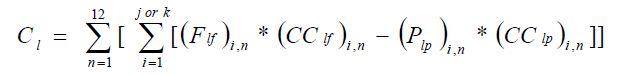
Where:
- Cl
- Annual net contribution to calculated emissions from carbon in liquid materials, including liquid organic wastes (kg/yr).
- (Flf)i,n
- Volume or mass of liquid feedstock i introduced in month “n” (m3 of feedstock). If a mass flow meter is used, measure the liquid feedstock in month “n” introduced in kg and measure the carbon content of feedstock in kg of C per kg of feedstock.
- (CClf)i,n
- Average carbon content of liquid feedstock i for month “n” (kg of C per m3 of feedstock when feedstock usage is measured in m3 , or kg of C per kg of feedstock when feedstock usage is measured in kg).
- (Plp)i,n
- Volume or mass of liquid product i produced in month “n” (m3). If a mass flow meter is used, measure the liquid product produced in kg and measure the carbon content of liquid product in kg of C per kg of product.
- (CClp)i,n
- Average carbon content of liquid product i, including organic liquid wastes, for month “n” (kg of C per m3 of product when liquid product is measured in m3, or kg of C per kg of product when product is measured in kg)
- j
- Number of feedstocks.
- k
- Number of products.
Solid feedstocks and products. Use Equation 300-3 of this section to calculate the net annual carbon input or output from solid feedstocks and products. Note that the result will be a negative value if there are no solid feedstocks in the process but there are solid products.
Equation 300-3:
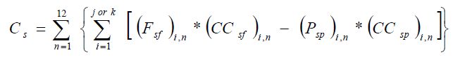
Where:
- Cs
- Annual net contribution to calculated emissions from carbon in solid materials (kg/yr).
- (Fsf)i,n
- Mass of solid feedstock i introduced in month “n” (kg).
- (CCsf)i,n
- Average carbon content of solid feedstock i for month “n” (kg C per kg of feedstock).
- (Psp)i,n
- Mass of solid product i produced in month “n” (kg).
- (CCsp)i,n
- Average carbon content of solid product i in month “n” (kg C per kg of product).
- j
- Number of feedstocks.
- k
- Number of products.
Annual emissions. Use the results from Equations 300-1 through 300-3 of this section, as applicable, in Equation 300-4 of this section to calculate annual CO2 emissions.
Equation 300-4:
CO2 = 0.001 × 3.664 × (Cg + Cl + Cs)Where:
- CO2
- Annual CO2 mass emissions from process operations and process off-gas combustion (tonnes/year).
- 0.001
- Conversion factor from kg to tonnes.
- 3.664
- Ratio of molecular weight, carbon dioxide to carbon.
- Calculation Methodology 3: (Optional combustion methodology for ethylene production processes) For ethylene production processes, calculate CO2, CH4, and N2O emissions as specified in paragraphs (c)(1) and (c)(2):
- For each flare, calculate CO2, CH4, and N2O emissions using the methodology for flares specified in ON.203(e).
- For all other combustion units, calculate the CO2 emissions from combustion of fuel that contains ethylene process off-gas using either Calculation Methodologies 3 or 4 in ON.23, respectively. Calculate CH4 and N2O emissions using the applicable method in ON.24 and the emission factors of 2.8 × 10⁻³ kg/GJ for CH4 and 5.7 × 10⁻⁴ kg/GJ for N2O. The person is not required to use the same calculation methodology for each stationary combustion unit that burns ethylene process off-gas.
ON.304 Sampling, Analysis, and Measurement Requirements
- If the person calculate emissions using the method specified in ON.303(a):
- Flares. The person shall comply with the monitoring requirements for flares specified in ON.204(e). The person may monitor the carbon content or the high heat value of the flares gas of flares in a petrochemical production facility on a quarterly basis.
- Process Vents. The person shall comply with the monitoring requirements for process vents specified in ON.204(b).
- If the person calculates emissions using the method specified in ON.303(b):
- Feedstock Consumption. The person shall measure the feedstock consumption using the same plant instruments used for accounting purposes, such as weigh hoppers, belt weigh feeders, or flow meters.
- Product Production. The person shall measure the amount of product produced using the same plant instruments used for accounting purposes. Equipment used to measure the production quantity shall be:
- calibrated according to the manufacturer’s instructions and
- maintained an accuracy of plus or minus 5%.
- Carbon Content. Except as allowed by ON.303(b)(4), the carbon content of each feedstock and product shall be measured at least once per month using one or more of the methods in Section 5 of this Guideline.
ON.305 Procedures for Estimating Missing Data
Unavailable analytical Data
- Whenever analytical data relating to sampling is unavailable, the person shall, using the methods prescribed in ON.304, re-analyze the original sample, a backup sample or a replacement sample for the same measurement and sampling period.
Determination of quantity
- Whenever sampling and measurement data required by ON.304 for the calculation of emissions is missing the person shall ensure that the data is replaced using the following missing data procedures:
- When the missing data concerns carbon content, temperature, pressure or gas concentration, the person shall,
Determine the sampling or measurement rate using the following Equation 300-5:
Equation 300-5:
R = QSAct ⁄ QSRequired
Where:
- When the missing data concerns carbon content, temperature, pressure or gas concentration, the person shall,
- R
- Sampling or measurement rate that was used, expressed as a percentage
- QSAct
- Quantity of actual samples or measurements obtained by the person
- QSRequired
- Quantity of samples or measurements required under ON.304
- Replace the missing data as follows,
- If R ≥ 0.9: replace the missing data by the arithmetic mean of the sampling or measurement data from immediately before and after the missing data period. If no data is available from before the missing data period, the person shall use the first available data from after the missing data period;
- If 0.75 ≤ R < 0.9: replace the missing data by the highest data value sampled or analyzed during the reporting period for which the calculation is made;
- If R < 0.75: replace the missing data by the highest data value sampled or analyzed during the 3 preceding years;
- When the missing da generated from best estimates based on all of the data relating to the processes ta concerns coke burn, volumetric gas flow, gas volume, number of hours of operation, quantity of raw materials, quantity of product, quantity of steam or quantity of wastewater treated, the replacement data shall be estimated on the basis of all the data relating to the processes used.
- For all units subject to the requirements of ON.20 that monitor and report emissions using a CEMS, the missing data backfilling procedures in EPS 1/PG/7 shall be followed for CO2 concentration, stack gas flow rate, fuel flow rate, high heating value, and fuel carbon content.
ON.390 Petroleum Product Supply
ON.391 Activity Definitions
For the purposes of this method, the following definitions apply:
- Co-process
- means processing biomass feedstock material together with petroleum crude oil or petroleum based feedstock in a refinery to produce one or more petroleum products.
- Fractionator
- means the owner and operator of a fractionation facility.
- Refiner
- means the owner and operator of a petroleum refinery.
- Petroleum product
- means a product listed in Table 390-1.
- Petroleum product supply
- has the same meaning as in the Regulation.
- Propane
- means propane used for fuel purposes as defined in Canadian General Standards Board standard CGSB 3.14 – Propane for Fuel Purposes,.
- Reference condition
- means 15 degress Celsius and 101.325 kilopascal.
- Supplier
- means a person who engages in petroleum product supply
ON.392 Greenhouse Gas Reporting Requirements
- A supplier shall set out the following information, calculated for the calendar year using standard quantification methods ON.390 - ON.395, in an emission report prepared for a calendar year in respect of petroleum product supply:
- The total greenhouse gas emissions calculated using Equation 390-4 and 390-5 expressed as tonnes of CO2e
- The annual quantity in tonnes or kilolitres of each product in Equation 390-1 that is first placed into the Ontario market.
- The volume of biomass-based fuel blended with each petroleum producti reported in (a)(2) of this section calculated in accordance with Equation 390-8.
- The total annual greenhouse gas emissions, expressed in tonnes of CO2e, that would result from the complete combustion or oxidation of each petroleum product reported in section (a)(1) above, calculated in accordance with ON.393(a).
- The organization name and facility location of each capped participant to which the person has supplied petroleum products during the year, along with the volume of petroleum products that are not automotive gasoline or diesels delivered to each facility, calculated in accordance with ON.393(c).
- A copy of any attestation received by the supplier from capped participants to which fuel was supplied by the supplier either directly or through a series of transactions that originated with the supplier for the purposes of the calculation in Equation 390-3. In order to be used for the purposes of Equation 390-3 the attestations must:
- be signed by the capped participant and
- confirm the total quantity of petroleum products received at the capped participant’s facility in the year from the supplier that supplied the petroleum product either directly or though a chain of transactions that originated with the supplier.
- In addition to the requirements in ON.390.(a), refiners and fractionators shall include the following information in the annual report prepared pursuant to the reguation:
- The volume of each type of biomass that was co-processed with petroleum feedstock to produce a petroleum product listed in Table 390-1 expressed in tonnes or kilolitres.
- The CO2 emissions, expressed in tonnes that would result from the complete combustion or oxidation of each type of biomass feedstock co-processed with petroleum feedstocks reported in ON.392(a)(3) above, calculated in accordance with ON.393(b).
ON.393 Calculating CO2 emissions
A supplier shall calculate CO2 emissions for each petroleum product supplied using Equation 390-1.
Equation 390-1:
CO2i = Producti × EFi
Where:
- CO2i
- Total annual CO2e emissions that would result from the complete combustion or oxidation of each petroleum product “i” expressed in tonnes.
- Producti
- Total annual quantity of petroleum product “i” calculated in accordance with paragraph (g) of this section that is first placed into the Ontario market by the supplier expressed in kilolitres for liquid petroleum products or tonnes for solid petroleum products.
- EFi
- Product-specific CO2e emission factor calculated in accordance with ON 393(f) expressed in tonnes of CO2e per kilolitre or per tonne of petroleum product.
A supplier shall use Equation 390-2 to calculate CO2 emissions for each type of biomass that enters a manufacturing or fractionating facility and is co-processed.
Equation 390-2:
CO2m_i = Producti × EFi × %Biomassm × 0.01Where:
- CO2m
- Total annual CO2e emissions that would result from the complete combustion or oxidation of petroleum product “i” produced from biomass “m” expressed in tonnes.
- Producti
- Total annual volume of petroleum product “i” first placed into the Ontario market by the supplier expressed in kilolitres.
- EFi
- Product-specific CO2e emission factor calculated in accordance with ON.393(f) expressed in tonnes of CO2e per kilolitre.
- %Biomassm
- Annual per cent of biomassm that enters the manufacturing or fractionating facility that is co-processed with petroleum or natural gas liquid feedstocks to produce a petroleum product reported under paragraph (a) of this section expressed in per cent volume for liquids and per cent weight for solid biomass.
A supplier shall use Equation 390-3 to calculate CO2 emissions from petroleum products that are supplied to a capped participant.
Equation 390-3:
CO2_le_i = Productle_i × EFiWhere:
- CO2_le_i
- Total annual CO2e emissions that would result from the complete combustion or oxidation of petroleum product “i” supplied to a capped participant, expressed in tonnes.
- Productle_i
- Total annual volume of petroleum products that are not automotive gasoline or diesels first placed into the Ontario market that are supplied to a capped participant and recorded in the attestation or attestations provided pursuant to in 392(a)(6).
- EFi
- Product-specific CO2e emission factor calculated in accordance with ON 393(f) expressed in tonnes of CO2e per kilolitre or per tonne of petroleum product.
Manufacturers and fractionators shall calculate the total CO2e emissions from all petroleum products supplied using Equation 390-4:
Equation 390-4:
CO2r = ∑(CO2i) − ∑(CO2m_i) − ∑(CO2_le_i)
Importers shall calculate the total CO2e emissions from all petroleum products imported using Equation 390-5:
Equation 390-5:
CO2x = ∑(CO2i) − ∑(CO2m_i) − ∑(CO2_le_i)
- Suppliers shall determine the emission factors (EFi) for each petroleum product using one of the following calculation methodologies. The same calculation methodology shall be used for the entire quantity of the petroleum product for the calendar year.
- Calculation Methodology 1. Use the default CO2e emission factor listed for the petroleum product in Table 390-1
- Calculation Methodology 2. Use Equation 390-6 with the following values
- For solid petroleum products, develop emission factors according to Equation 390-6 using direct measurements of carbon share according to methods set out in ON.394(c).
For non-solid petroleum products, develop emission factors according to Equation 390-6 using direct measurements of density and carbon share according to methods set out in ON.394(c).
Equation 390-6:
EFi = (Density × carbon share × 44⁄12) + 0.01 × (21 × EFCH4 + 310 × EFN2O)Where:
- EFi
- Emission factor of the petroleum product expressed in tonnes of CO2e per kilolitre or per tonne of petroleum product.
- Density
- Density of the petroleum product or natural gas liquid expressed in tonnes per kilolitre for non-solid petroleum products or having a value of 1 for solid petroleum products.
- Carbon share
- weight per cent of carbon in the petroleum product, expressed as a fraction such as expressing 75% as 0.75.
- 44/12
- Conversion factor for carbon to carbon dioxide.
- EFCH4
- CH4 Emisions factor of the petroleum product expressed in grams of CH4 per litre from the relevant table in ON.20.
- EFN2O
- N2O Emisions factor of the petroleum product expressed grams of N2O per litre from the relevant table in ON.20.
- The supplier that produces a petroleum product by blending a petroleum-based product with a biomass-based fuel shall calculate the volume of the petroleum product according to the following methodology.
Use Equation 390-8 to calculate productb for use in Equation 390-9:
Equation 390-8:
Productb = Productt × %Voli × 0.01Where:
- Productb
- Total volume of petroleum products that is biomass-based fuels in kilolitres
- Productt
- Total volume of petroleum products and blended biomass-based fuels that is used as a fuel in kilolitres.
- %Voli
- Percent volume of productt that is biomass.
Use Equation 390-9 to calculate producti
Equation 390-9:
Producti = Productt − Productb
ON.394 Sampling, Analysis, and Measurement Requirements
- Determination of quantity of petroleum products.
- The supplier required to determine the quantities of petroleum products pursuant to this method shall determine those quantities using the following:
- Appropriate standard methods published by a consensus-based standards organization; or,
- Where no such methods exist, industry standard practices.
- The supplier required to determine the quantities of petroleum products pursuant to this method shall determine those quantities using the following:
- Equipment Calibration.
- The supplier required to determine quantities of petroleum products pursuant to this method shall calibrate all measurement equipment prior to its first use for the purposes of this method using a standard method published by a consensus based standards organization or according to the calibration or verification procedures specified by the equipment manufacturer.
- The supplier required to determine quantities of petroleum products pursuant to this method shall recalibrate equipment mentioned in (1) at the minimum frequency specified by the standard method or by the equipment manufacturer.
- Sections (1) and (2) above do not apply to any equipment used for financial transactions.
- Procedures for determining emissions factors using direct measurements under Calculation Methodology 2 of ON.393(f)(2).
- A supplier required to determine emissions factors using direct measurements pursuant to ON.393(e)(2) shall collect at least one sample of each petroleum product using an appropriate standard method published by a consensus-based standards organization for each calendar month of the calendar year in which the petroleum product is supplied in Ontario.
- A supplier required to determine emissions factors shall ensure the mixing and handling of samples is performed using an appropriate standard method published by a consensus-based standards organization.
- A supplier required to determine density measurements shall use the following for each sample collected under (1).
- For all non-solid petroleum products, the supplier shall test for density using an appropriate standard method published by a consensus-based standards organization.
- The density value for each petroleum product shall be generated by a single composite sample or an average of multiple samples.
- All measurements of density shall be temperature-adjusted and pressure-adjusted to the reference conditions contained in this method.
- For each sample collected under (1) the supplier required to determine the carbon share measurement shall do the following:
- Test for carbon share using an appropriate standard method published by a consensus-based standards organization.
If the supplier uses a standard method that involves gas chromatography to determine the per cent mass of each component in a petroleum product the supplier shall calculate the petroleum product’s carbon share using Equation 390-7:
Equation 390-7:
Carbon Share = ∑(%Compositioni…n × %Massi…n)
Where:
- %Compositioni…n
- Per cent of total mass of each molecular component in the petroleum product
- %Massi…n
- Per cent of total mass that carbon represents in each molecular component of the petroleum product.
- The carbon share for each petroleum product shall be generated by a single composite sample or an average of multiple samples.
ON.395 Procedures for estimating missing data
Determination of quantity.
The supplier shall ensure that whenever the quantity of one or more petroleum products or types of biomass during any period is not measured the following missing data procedures are used:
- For quantities of a petroleum product that are purchased or sold, the missing data shall be substituted using the supplier’s established procedures for billing purposes.
- For quantities of a petroleum product that are not purchased or sold but for which the custody is transferred, the missing data shall be substituted using the supplier’s established procedures for tracking purposes.
Determination of emission factor.
Where any of the procedures in ON.393(f)(2) cannot be followed to develop an emission factor for any reason, the supplier shall use ON.393(f)(1) for the entire calendar year.
| Petroleum Products | Emission Factor (tonnes CO2e/kL) |
|---|---|
| Automotive Gasoline | 2.361 |
| Diesels | 3.007 |
| Light fuel oils (No. 1,2) | 2.735 |
| Heavy fuel oils (No. 3, 4, 5, 6) | 3.146 |
| Petroleum Coke | 3.837 |
| Propane* | 1.544 |
* The emission factors for propane are based on a reference condition of 15 degrees Celsius and saturation pressure.
ON.200 Petroleum Refining
ON.201 Activity Definition
For the purposes of this standard quantification method:
- Petroleum refining
- has the same meaning as in the Regulation.
- Person
- means a person that engages in petroleum refining.
- CAN-CWB Methodology
- means the calculation methodology described in “The CAN-CWB Methodology for Regulatory Support: Public Report” dated January 2014, prepared by Solomon Associates.
ON.202 Greenhouse Gas Reporting Requirements
A person shall set out the following information, calculated for the calendar year using standard quantification methods ON.200 – ON.205, in an emission report prepared for a calendar year in respect of petroleum refining at a facility:
- Catalyst Regeneration. Report CO2, CH4, and N2O emissions.
- Process Vents. Report CO2, N2O, and CH4 emissions.
- Asphalt Production. Report CO2 and CH4 emissions.
- Sulphur Recovery. Report CO2 emissions.
- Flares and Other Control Devices. Report CO2, N2O, and CH4 emissions.
- Above-Ground Storage Tanks. Report CH4 emissions.
- Wastewater Treatment. Report CH4 and N2O emissions from anaerobic treatment.
- Oil-water Separators. Report CH4 emissions from oil-water separators.
- Equipment Leaks. Report CH4 emissions.
- Petroleum Coke calcining units. Report CO2, N2O, and CH4 emissions.
- Uncontrolled blowdown systems. Report CH4 emissions.
- Loading Operations. Report CH4 emissions.
- Delayed Coking Units. Report CH4 emissions.
- The following Complexity weighted barrel (CWB) parameters:
- The Direct Only CAN-CWB(without hydrogen and cogeneration), in units of complexity weight barrel per calendar day (CWB/CD).
- The throughput for each of the Standard Refining Process units identified in the CAN-CWB Methodology.
- The Total CO2e emissions associated with the petroleum refinery, including emissions associated with Hydrogen Generation units (listed in Appendix B of the CAN-CWB Methodology), indirect emissions but excluding cogeneration emissions.
- The Direct-only CO2 emissions from the petroleum refinery including HydrogenGeneration units emissions but excluding cogeneration emissions.
- The Direct-only CO2 emissions from the petroleum refinery excluding Hydrogen Generation units and cogeneration emissions.
- The Total Input Barrels described in the CAN-CWB Methodology.
- The Non-Crude Input Barrels described in the CAN-CWB Methodology.
- The Imported Steam to the refinery, including steam originating from a cogeneration unit located inside the refinery.
- The Imported Electricity to the refinery, including electricity originating from a cogeneration unit located inside the refinery.
- The Exported Steam from the refinery, net of steam originating from a cogeneration unit located inside the refinery.
- The Exported Electricity from the refinery, net of electricity originating from a cogeneration unit located inside the refinery.
ON.203 Calculation of Greenhouse Gas Emissions
The person shall calculate emissions for the following sources at petroleum refineries: catalytic cracking units; fluid coking units; delayed coking units; catalytic reforming units; petroleum coke calcining units; asphalt blowing operations; blowdown systems; storage tanks; process equipment components (compressors, pumps, valves, pressure relief devices, flanges, and connectors) in gas service; marine vessel, barge, tanker truck, and similar loading operations; flares; and sulphur recovery plants. The person must report emissions from hydrogen production under the hydrogen production method.
The person shall calculate GHG emissions using the methods in paragraphs (a) through (i) of this section. If a continuous emissions monitor is used to measure CO2 emissions from process vents, asphalt production, sulphur recovery, or other control devices then the person shall calculate the CO2 emissions from these processes using a continuous emissions monitoring system (CEMS) as specified in Calculation Methodology 4 of ON.23. When the flue gas from two or more processes or stationary combustion sources are discharged through a common stack or duct before exiting to the atmosphere and if CEMS as specified in Calculation Methodology 4 of ON.23 are used to continuously monitor the CO2 emissions, a person may report the combined emissions from the processes or stationary combustion sources sharing the common stack or duct instead of separately reporting the GHG emission from individual processes or stationary combustion sources.
- Catalyst Regeneration. The person shall calculate the CO2, CH4, and N2O process emissions resulting from catalyst regeneration using the methods in paragraph (a)(1), (a)(2) and (a)(3), respectively.
- For units equipped with CEMS, the person shall calculate CO2 process emissions resulting from catalyst regeneration using CEMS in accordance with Calculation Methodology 4 of ON.23. In the absence of CEMS data, the person shall use the methods in paragraphs (a)(1)(A) through (a)(1)(C).
The person shall calculate process CO2 emissions from the continuous regeneration of catalyst material in fluid catalytic cracking units (FCCU) and fluid cokers using Equations 200-1, 200-1b, 200-2, and 200-3 in section (a)(1)(A)(ii) below.
Equation 200-1:
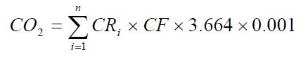
Where:
- CO2
- CO2 emissions (tonnes/year)
- n
- number of hours of operation in the report year
- CRi
- hourly coke burn rate in kg/hr
- CF
- carbon fraction in coke burned
- 3.664
- ratio of molecular weights, carbon dioxide to carbon
- 0.001
- conversion factor from kg to tonnes
Alternatively, the person may calculate process CO2 emissions from the continuous regeneration of catalyst material in fluid catalytic cracking units (FCCU) and fluid cokers using Equations 200-1b and 200-2.
Equation 200-1b:
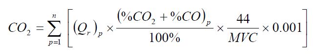
Where:
- CO2
- CO2 emissions (tonnes/year)
- Qr
- volumetric flow rate of exhaust gas before entering the emission control system using equation 200-2 and at reference temperature and pressure conditions as used by the facility (dRm3/hr)
- %CO2
- average hourly CO2 concentration in regenerator exhaust, per cent by volume – dry basis
- %CO
- average hourly CO concentration in regenerator exhaust, per cent by volume – dry basis. When there is no post-combustion device, assume %CO to be zero.
- 44
- molecular weight of CO2 (kg/kg-mole)
- MVC
- molar volume conversion factor at the same reference conditions as the above Qr (Rm3/kg-mole)
8.3145 × [273.16 + reference temperature in °C] ⁄ [reference pressure in kilopascal]
- 0.001
- conversion factor from kg to tonnes
- n
- number of hours of operation in the report year
Either continuously monitor the volumetric flow rate of exhaust gas from the fluid catalytic cracking unit regenerator or fluid coking unit burner prior to the combustion of other fossil fuels or calculate the volumetric flow rate of this exhaust gas stream using Equation 200-2 of this section.
Equation 200-2:
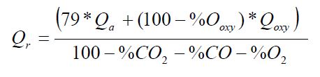
Where:
- Qr
- volumetric flow rate of exhaust gas from regenerator before entering the emission control system at reference temperature and pressure conditions as used by the facility (dRm3/min)
- Qa
- volumetric flow rate of air to regenerator, as determined from control room instrumentation at reference temperature and pressure conditions used for Qr (dRm3/min)
- %Qxy
- oxygen concentration in oxygen enriched air stream, per cent by volume – dry basis
- Qoxy
- volumetric flow rate of O2 enriched air to regenerator as determined from catalytic cracking unit control room instrumentation at reference temperature and pressure conditions used for Qr (dRm3/min)
- %CO2
- carbon dioxide concentration in regenerator exhaust, per cent by volume – dry basis
- %CO
- CO concentration in regenerator exhaust, per cent by volume – dry basis. When no auxiliary fuel is burned and a continuous CO monitor is not required, assume %CO to be zero
- %O2
- O2 concentration in regenerator exhaust, per cent by volume – dry basis
Calculate the hourly coke burn rate using Equation 200-3 or from facility measurement or engineering estimate:
Equation 200-3:
CRi = K1Qr × (%CO2 + %CO) + K2Qa − K3Qr × [%CO ⁄ 2 + %CO2 + %O2] + K3Qoxy × (%Ooxy)Where:
- CRi
- hourly coke burn rate in kg/hr
- K1, K2, K3
- material balance and conversion factors (K1, K2, and K3 from Table 200-1 or from facility measurement or engineering estimate
- Qr
- volumetric flow rate of exhaust gas before entering the emission control system from Equation 200-2 (dRm3/min)
- Qa
- volumetric flow rate of air to regenerator as determined from control room instrumentation at reference temperature and pressure conditions used in Qr (dRm3/min)
- %CO2
- CO2 concentration in regenerator exhaust, per cent by volume – dry basis
- %CO
- CO concentration in regenerator exhaust, per cent by volume – dry basis
- %O2
- O2 concentration in regenerator exhaust, per cent by volume – dry basis
- Qoxy
- volumetric flow rate of O2 enriched air to regenerator as determined from control room instrumentation at reference temperature and pressure conditions used in Qr (dRm3/min)
- %Oxy
- O2 concentration in O2 enriched air stream inlet to regenerator, per cent by volume – dry basis
The person shall calculate process CO2 emissions resulting from continuous catalyst regeneration in operations other than FCCUs and fluid cokers (e.g. catalytic reforming) using Equation 200-4:
Equation 200-4:
CO2 = CCirc × (CFspent − CFregen) × H × 3.664
Where:
- CO2
- CO2 emissions (tonnes/year)
- CCirc
- average catalyst regeneration rate (tonnes/hour)
- CFspent
- weight carbon fraction on spent catalyst
- CFregen
- weight carbon fraction on regenerated catalyst (default = 0)
- H
- hours regenerator was operational (hr/yr)
- 3.664
- ratio of molecular weights, CO2 to carbon
The person shall calculate process CO2 emissions resulting from periodic catalyst regeneration using Equations 200-5:
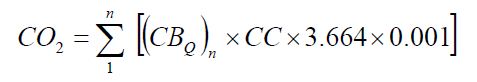
Where:
- CO2
- Annual CO2 emissions (tonnes/year).
- CBQ
- Coke burn-off quantity per regeneration cycle from engineering estimates (kg coke/cycle).
- n
- Number of regeneration cycles in the calendar year.
- CC
- Carbon content of coke based on measurement or engineering estimate (kg C per kg coke); default = 0.94.
- 3.664
- ratio of molecular weights, carbon dioxide to carbon
- 0.001
- Conversion factor (tonne/kg).
Calculate CH4 emissions using either unit specific measurement data, a unit-specific emission factor based on a source test of the unit, or Equation 200-6 of this section.
Equation 200-6:
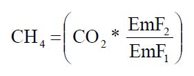
Where:
- CH4
- Annual methane emissions from coke burn-off (tonnes CH4/year).
- CO2
- Emission rate of CO2 from coke burn-off calculated in paragraph (a)(1) of this section, as applicable (tonnes/year).
- EmF1
- Default CO2 emission factor for petroleum coke of 97 kg CO2/GJ
- EmF2
- Default CH4 emission factor of 2.8 × 10⁻³ kg CH4/GJ.
Calculate N2O emissions using either unit specific measurement data, a unit-specific emission factor based on a source test of the unit, or Equation 200-7 of this section.
Equation 200-7:
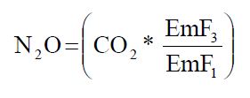
Where:
- N2O
- Annual nitrous oxide emissions from coke burn-off (tonne N2O/year).
- CO2
- Emission rate of CO2 from coke burn-off calculated in paragraphs (a)(1) of this section, as applicable (tonnes/year).
- EmF1
- Default CO2 emission factor for petroleum coke of 97 kg CO2/GJ.
- EmF3
- Default N2O emission factor of 5.7 × 10⁻⁴ kg N2O/GJ
Process Vents. Except for process emissions reported under other requirements of this Regulation, the person shall calculate process emissions of CO2, CH4, and N2O from process vents using Equation 200-8 for each process vent that can be reasonably expected to contain greater than 2 per cent by volume CO2 or greater than 0.5 per cent by volume of CH4 or greater than 0.01 per cent by volume (100 parts per million) of N2O.
Equation 200-8:
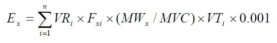
Where:
- Ex
- Annual emissions of x (tonnes/yr), where x = CO2, N2O, or CH4
- VRi
- Average volumetric flow rate for venting event i from measurement data, process knowledge or engineering estimates at reference temperature and pressure conditions as used by the facility (Rm3/unit time). If a mass flow meter is used, measure the flow rate in kg/unit time and replace the term “MWx⁄MVC” with “1”.
- Fxi
- Molar fraction of x in vent gas stream during event i from measurement data, process knowledge or engineering estimates.
- MWx
- molecular weight of x (kg/kg-mole)
- MVC
- molar volume conversion factor at the same reference conditions as the above VRi (Rm3/kg-mole).
- 8.3145 × [273.16 + reference temperature in °C] ⁄ [reference pressure in kilopascal]
- VTi
- time duration of venting event i, in same units of time as VRi
- n
- number of venting events in report year
- 0.001
- conversion factor from kg to tonnes
- Asphalt Production. The person shall calculate CO2 and CH4 process emissions from asphalt blowing activities using either process vent method specified in paragraph (b) or according to the applicable provisions in paragraphs (c)(1) and (c)(2) of this section.
For uncontrolled asphalt blowing operations or asphalt blowing operations controlled by vapor scrubbing, calculate CO2 and CH4 emissions using Equations 200-9 and 200-10 of this section, respectively.
Equation 200-9:
CO2 = (QAB × EFAB, CO2)Where:
- CO2
- Annual CO2 emissions from uncontrolled asphalt blowing (tonnes CO2/year).
- QAB
- Quantity of asphalt blown (MMbbl/year).
- EFAB, CO2
- Emission factor for CO2 from uncontrolled asphalt blowing from facility-specific test data (tonnes CO2/MMbbl asphalt blown); default = 1,100.
Equation 200-10:
CH4 = (QAB × EFAB, CH4)Where:
- CH4
- Annual methane emissions from uncontrolled asphalt blowing (tonnes CH4/year).
- QAB
- Quantity of asphalt blown (MMbbl/year).
- EFAB, CH4
- Emission factor for CH4 from uncontrolled asphalt blowing from facility-specific test data (tonnes CH4/MMbbl asphalt blown); default = 580.
For asphalt blowing operations controlled by thermal oxidizer or flare, calculate CO2 and CH4 emissions using Equations 200-11 and 200-12 of this section, respectively, provided these emissions are not already included in the flare emissions calculated in paragraph (e) of this section or in the stationary combustion unit emissions required under ON.20.
Equation 200-11:
CO2 = 0.98 × (QAB × CEFAB × 3.664)Where:
- CO2
- Annual CO2 emissions from controlled asphalt blowing (tonnes CO2/year).
- 0.98
- Assumed combustion efficiency of thermal oxidizer or flare.
- QAB
- Quantity of asphalt blown (MMbbl/year).
- CEFAB
- Carbon emission factor from asphalt blowing from facility-specific test data (tonnes C/MMbbl asphalt blown); default = 2,750.
- 3.664
- ratio of molecular weights, carbon dioxide to carbon
Equation 200-12:
CH4 = 0.02 × (QAB × EFAB, CH4)Where:
- CH4
- Annual methane emissions from controlled asphalt blowing (tonnes CH4/year).
- 0.02
- Fraction of methane uncombusted in thermal oxidizer or flare based on assumed 98% combustion efficiency.
- QAB
- Quantity of asphalt blown (MMbbl/yr).
- EFAB, CH4
- Emission factor for CH4 from uncontrolled asphalt blowing from facility-specific test data (tonnes CH4/MMbbl asphalt blown); default = 580.
Sulphur Recovery. The person shall calculate CO2 process emissions from sulphur recovery units (SRUs) using Equation 200-13. For the molar fraction (MF) of CO2 in the sour gas, use either a default factor of 0.20, engineering estimates or a source specific molar fraction value derived from source tests conducted at least once per calendar year The source test shall be repeated in each future year to update the source specific emission factors annually.
Equation 200-13:
CO2 = FR × MWCO2 ⁄ MVC × MF × 0.001Where:
- CO2
- emissions of CO2 (tonnes/year)
- FR
- volumetric flow rate of acid gas to SRU at reference temperature and pressure conditions as used by the facility (Rm3/year). If a mass flow meter is used, measure the acid gas flow in kg per year and replace the term “MWCO2⁄MVC” with “1”
- MWCO2
- molecular weight of CO2 (44 kg/kg-mole)
- MVC
- molar volume conversion factor at the same reference conditions as the above FR (Rm3/kg-mole).
- 8.3145 × [273.16 + reference temperature in °C] ⁄ [reference pressure in kilopascal]
- MF
- molar fraction (%) of CO2 in sour gas based on measurement or engineering estimate (default MF = 20% expressed as 0.20)
- 0.001
- conversion factor from kg to tonnes
- Flares and Other Control Devices.
- The person shall calculate and report CO2, CH4 and N2O emissions resulting from the combustion of flare pilot gas using the appropriate method(s) specified in section ON.23 or ON.24.
- The person shall calculate and report CO2 emissions resulting from the combustion of hydrocarbons routed to flares for destruction as follows:
- Heat value or carbon content measurement. If the person has a continuous high heat value monitor or gas composition monitor on the flare or if the person monitors these parameters at least weekly, the person shall use the measured heat value or carbon content value in calculating the CO2 emissions from the flare using the applicable methods in paragraphs (e)(2)(i)(A) and (e)(2)(i)(B).
If the person monitors gas composition, calculate the CO2 emissions from the flare using Equation 200-14 of this section. If daily or more frequent measurement data is available, the person shall use daily values when using Equation 200-14 of this section; otherwise, use weekly values.
Equation 200-14:
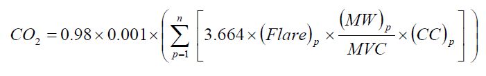
Where:
- Heat value or carbon content measurement. If the person has a continuous high heat value monitor or gas composition monitor on the flare or if the person monitors these parameters at least weekly, the person shall use the measured heat value or carbon content value in calculating the CO2 emissions from the flare using the applicable methods in paragraphs (e)(2)(i)(A) and (e)(2)(i)(B).
- CO2
- Annual CO2 emissions for a specific fuel type (tonnes/year).
- 0.98
- Assumed combustion efficiency of a flare.
- 0.001
- Conversion factor from kg to tonnes.
- n
- Number of measurement periods. The minimum value for n is 52 (for weekly measurements); the maximum value for n is 366 (for daily measurements during a leap year).
- p
- Measurement period index.
- 3.664
- Ratio of molecular weights, carbon dioxide to carbon
- (Flare)p
- Volume of flare gas combusted during measurement period at reference temperature and pressure conditions as used by the facility (Rm3/period). If a mass flow meter is used, measure flare gas flow rate in kg/period and replace the term “(MW)p⁄MVC” with “1”.
- (MW)p
- Average molecular weight of the flare gas combusted during measurement period (kg/kg-mole). If measurements are taken more frequently than daily, use the arithmetic average of measurement values within the day to calculate a daily average.
- MVC
- Molar volume conversion factor at the same reference conditions as the above (Flare)p (Rm3/kg-mole).
- 8.3145 × [273.16 + reference temperature in °C] ⁄ [reference pressure in kilopascal]
- (CC)p
- Average carbon content of the flare gas combusted during measurement period (kg C per kg flare gas). If measurements are taken more frequently than daily, use the arithmetic average of measurement values within the day to calculate a daily average.
If the person monitors heat content but do not monitor gas composition, calculate the CO2 emissions from the flare using Equation 200-15 of this section. If daily or more frequent measurement data is available, the person shall use daily values when using Equation 200-15 of this section; otherwise, use weekly values.
Equation 200-15:
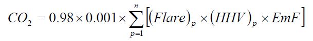
Where:
- CO2
- Annual CO2 emissions for a specific fuel type (tonnes/year).
- 0.98
- Assumed combustion efficiency of a flare.
- 0.001
- Conversion factor from kg to tonnes.
- n
- Number of measurement periods. The minimum value for n is 52 (for weekly measurements); the maximum value for n is 366 (for daily measurements during a leap year).
- p
- Measurement period index.
- (Flare)p
- Volume of flare gas combusted during measurement period at reference temperature and pressure conditions as used by the facility (Rm3/period). If a mass flow meter is used, the person shall also measure molecular weight and convert the mass flow to a volumetric flow as follows: Flare[m3] = Flare [kg] × MVC⁄(MW)p, where MVC is the molar volume conversion factor at the same reference conditions as (Flare)p (Rm3/kg-mole) and (MW)p is the average molecular weight of the flare gas combusted during measurement period (kg/kg-mole).
8.3145 × [273.16 + reference temperature in °C] / [reference pressure in kilopascal])
- (HHV)p
- High heat value for the flare gas combusted during measurement period (GJ per Rm3,). If measurements are taken more frequently than daily, use the arithmetic average of measurement values within the day to calculate a daily average.
- EmF
- Default CO2 emission factor of 57 kilograms CO2/GJ (HHV basis).
- Alternative Method. For startup, shutdown, and malfunctions during which the person were unable to measure the parameters required by Equations 200-14 and 200-15 of this section, the person shall determine the quantity of gas discharged to the flare separately for each start-up, shutdown, or malfunction, and calculate the CO2 emissions as specified in paragraphs (e)(2)(ii)(A) of this section.
- For periods of start-up, shutdown, or malfunction, use engineering calculations and process knowledge to estimate the carbon content of the flared gas for each start-up, shutdown, or malfunction event.
- For the reporting of emissions from normal operation flares in the year 2011, the person may use the average heating value measured for the fuel gas for the heating value of the flare gas. If heating value is not measured, the heating value may be estimated from historic data or engineering calculation. If the person is unable to use the methods in ON.203(e)(2)(i) for the reporting of emissions from normal operation of flares in the year 2012 due to health or safety reasons, the person may use the alternate method in the subsection for the reporting of emissions from normal operation of flares in the year 2012 if it is consented to in writing by the Director.
Calculate the CO2 emissions using Equation 200-16 of this section.
Equation 200-16:
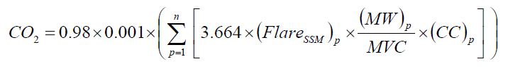
Where:
- CO2
- Annual CO2 emissions for a specific fuel type (tonnes/year).
- 0.98
- Assumed combustion efficiency of a flare.
- 0.001
- Conversion factor from kg to tonnes.
- n
- Number of start-up, shutdown, and malfunction events during the calendar year.
- p
- Start-up, shutdown, malfunction and other measurement period index.
- (FlareSSM)p
- Volume of flare gas combusted during indexed start-up, shutdown, or malfunction event from engineering calculations, at reference temperature and pressure conditions as used by the facility (Rm3/event). If a mass flow meter is used, measure the flare gas combusted in kg per event and replace the term “(MW)p⁄MVC” with “1”.
- (MW)p
- Average molecular weight of the flare gas, from the analysis results or engineering calculations for the event (kg/kg-mole).
- MVC
- Molar volume conversion factor at the same reference conditions as the above (FlareSSM)p (Rm3/kg-mole).
- 8.3145 × [273.16 + reference temperature in °C] ⁄ [reference pressure in kilopascal]
- (CC)p
- Average carbon content of the flare gas, from analysis results or engineering calculations for the event (kg C per kg flare gas).
- 3.664
- Ratio of molecular weights, carbon dioxide to carbon
- The person shall calculate and report CH4 and N2O emissions resulting from the combustion of hydrocarbons routed to flares for destruction using the methods specified in paragraphs (e)(3)(A) and (e)(3)(B):
Calculate CH4 using Equation 200-17 of this section.
Equation 200-17:

Where:
- CH4
- Annual methane emissions from flared gas (tonnes CH4/year).
- CO2
- Emission rate of CO2 from flared gas calculated in paragraph (e)(1) and (e)(2) of this section (tonnes/year).
- EmFCH4
- Default CH4 emission factor for Petroleum Products of 2.8 × 10⁻³ kg/GJ
- EmF
- Default CO2 emission factor for flare gas of 57 kilograms CO2/GJ (HHV basis).
- 0.02⁄0.98
- correction factor for flare combustion efficiency.
- 16⁄44
- correction factor ratio of the molecular weight of CH4 to CO2
- fCH4
- Weight fraction of carbon in the flare gas prior to combustion that is contributed by methane from measurement values or engineering calculations (kg C in methane in flare gas/kg C in flare gas); default is 0.4.
Calculate N2O emissions using Equation 200-18 of this section.
Equation 200-18:
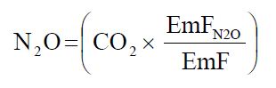
Where:
- N2O
- Annual nitrous oxide emissions from flared gas (tonnes N2O/year).
- CO2
- Emission rate of CO2 from flared gas calculated in paragraph (e)(1) and (e)(2) of this section (tonnes/year).
- EmFN2O
- Default N2O emission factor for petroleum products of 5.7 × 10⁻⁴ kg/GJ.
- EmF
- Default CO2 emission factor for flare gas of 57 kilograms CO2/GJ (HHV basis).
The person who uses methods other than flares (e.g. incineration, combustion as a supplemental fuel in heaters or boilers) to destroy low Btu gases (e.g. coker flue gas, gases from vapor recovery systems, casing vents and product storage tanks) shall calculate CO2 emissions using Equation 200-19. The person shall determine CCA and MWA quarterly using methods specified in ON.20 and use the annual average values of CCA and MWA to calculate CO2 emissions.
Equation 200-19:
CO2 = GVA × CCA × MWA ⁄ MVC × 3.664 × 0.001Where:
- CO2
- CO2 emissions (tonnes/year)
- GVA
- volume of gas A destroyed annually at reference temperature and pressure conditions as used by the facility (Rm3/year). If a mass flow meter is used, measure the gas destroyed in kg and replace the term “MWA⁄MVC” with “1”.
- CCA
- carbon content of gas A (kg C/kg fuel)
- MWA
- molecular weight of gas A
- MVC
- molar volume conversion factor at the same reference conditions as the above GVA (Rm3/kg-mole).
- 8.3145 × [273.16 + reference temperature in °C] ⁄ [reference pressure in kilopascal]
- 3.664
- ratio of molecular weights, carbon dioxide to carbon
- 0.001
- conversion factor from kg to tonnes
- Storage Tanks. For storage tanks other than those processing unstabilized crude oil except as provided in paragraph (f)(3) of this section, calculate CH4 emissions using the applicable methods in paragraphs (f)(1) and (f)(2) of this section.
For storage tanks other than those processing unstabilized crude oil, the person shall either calculate CH4 emissions from storage tanks that have a vapor-phase methane concentration of 0.5 volume per cent or more using tank-specific methane composition data (from measurement data or product knowledge) and the AP-42 emission estimation methods provided in Section 7.1 of the AP-42: “Compilation of Air Pollutant Emission Factors, Volume 1: Stationary Point and Area Sources”, including TANKS Model (Version 4.09D) or similar programs, or estimate CH4 emissions from storage tanks using Equation 200-20 of this section.
Equation 200-20:
CH4 = (0.1 × QReƒ)Where:
- CH4
- Annual methane emissions from storage tanks (tonnes/year).
- 0.1
- Default emission factor for storage tanks (tonne CH4/MMbbl).
- QReƒ
- Quantity of crude oil plus the quantity of intermediate products received from off site that are processed at the facility (MMbbl/year).
For storage tanks that process unstabilized crude oil, calculate CH4 emissions from the storage of unstabilized crude oil using either tank-specific methane composition data (from measurement data or product knowledge) and direct measurement of the gas generation rate or by using Equation 200-21 of this section.
Equation 200-21:
CH4 = (995000 × Qun × ΔP) × MFCH4 × (16 ⁄ MVC) × 0.001Where:
- CH4
- Annual methane emissions from storage tanks (tonnes/year).
- Qun
- Quantity of unstabilized crude oil received at the facility (MMbbl/year).
- ΔP
- Pressure differential from the previous storage pressure to atmospheric pressure (psi).
- MFCH4
- Mole fraction of CH4 in vent gas from the unstabilized crude oil storage tank from facility measurements (kg-mole CH4/kg-mole gas); use 0.27 as a default if measurement data is not available.
- 995,000
- Correlation Equation factor (cubic feet gas per MMbbl per psi)
- 16
- Molecular weight of CH4 (kg/kg-mole).
- MVC
- Molar volume conversion (849.5 cubic feet/kg-mole).
- 0.001
- Conversion factor (tonne/kg).
- The person does not need to calculate CH4 emissions from storage tanks that meet any of the following descriptions:
- Units permanently attached to conveyances such as trucks, trailers, rail cars, barges, or ships;
- Pressure vessels designed to operate in excess of 204.9 kilopascals and without emissions to the atmosphere;
- Bottoms receivers or sumps;
- Vessels storing wastewater; or
- Reactor vessels associated with a manufacturing process unit.
- Industrial Wastewater Processing
The person shall calculate CH4 emissions from anaerobic wastewater treatment (such as anaerobic reactor, digester, or lagoon) using Equation 200-22 or Equation 200-23.
Equation 200-22:
CH4 = Q × CODqave × B × MCF × 0.001Equation 200-23:
CH4 = Q × BOD5qave × B × MCF × 0.001Where:
- CH4
- emission of methane (tonnes/year)
- Q
- volume of wastewater treated (m³/yr)
- CODqave
- average of quarterly determinations of chemical oxygen demand of the wastewater (kg/m3)
- BOD5qave
- average of quarterly determinations of five-day biochemical oxygen demand of the wastewater (kg/m3)
- B
- methane generation capacity (B = 0.25 kg CH4/kg COD and 0.06 kg CH4/kg BOD5)
- MCF
- methane correction factor for anaerobic decay (0 1.0) from Table 200-2
- 0.001
- conversion factor from kg to tonnes
- For anaerobic processes from which biogas is recovered and not emitted, the person shall adjust the CH4 emissions calculated in paragraph (g)(1) by the amount of CH4 collected.
The person shall calculate N2O emissions from wastewater treatment using Equation 200-24:
Equation 200-24:
N2O = Q × Nqave × EFN2O × 1.571 × 0.001
Where:
- N2O
- emissions of N2O (tonnes/year)
- Q
- volume of wastewater treated (m³/yr)
- Nqave
- average of quarterly determinations of N in effluent (kg N/m³)
- EFN2O
- emission factor for N2O from discharged wastewater (0.005 kg N2O-N/kg N)
- 1.571
- conversion factor - kg N2O-N to kg N2O
- 0.001
- conversion factor from kg to tonnes
Oil-Water Separators. The person shall calculate CH4 emissions from oil-water separators using Equation 200-25. For the CFNMHC conversion factor, the person shall use either a default factor of 0.6 or species specific conversion factors determined by sampling and analysis.
Equation 200-25:
CH4 = EFsep × Vwater × CFNMHC × 0.001Where:
- CH4
- emission of methane (tonnes/year)
- EFsep
- NMHC (non methane hydrocarbon) emission factor (kg/m³) from Table 200-3.
- Vwater
- volume of waste water treated by the separator (m³/yr)
- CFNMHC
- NMHC to CH4 conversion factor
- 0.001
- conversion factor from kg to tonnes
- Equipment leaks. Calculate CH4 emissions using the method specified in either paragraph (i)(1) or (i)(2) of this section.
- Use process-specific methane composition data (from measurement data or process knowledge) and any of the emission estimation procedures provided in the Protocol for Equipment Leak Emissions Estimates (EPA-453/R-95-017, NTIS PB96-175401).
Use Equation 200-26 of this section.
Equation 200-26:
CH4 = (0.4 × NCD + 0.2 × NPU1 + 0.1 × NPU2 + 4.3 × NH2 + 6 × NFGS)Where:
- CH4
- Annual methane emissions from equipment leaks (tonnes/year)
- NCD
- Number of atmospheric crude oil distillation columns at the facility.
- NPU1
- Cumulative number of catalytic cracking units, coking units (delayed or fluid), hydrocracking, and full-range distillation columns (including depropanizer and debutanizer distillation columns) at the facility.
- NPU2
- Cumulative number of hydrotreating/hydrorefining units, catalytic reforming units, and visbreaking units at the facility.
- NH2
- Total number of hydrogen plants at the facility.
- NFGS
- Total number of fuel gas systems at the facility.
- Petroleum Coke Calcining. The person shall calculate GHG emissions according to the applicable provisions in paragraphs (j)(1) through (j)(3) of this section.
- If the person operates and maintains a CEMS that measures CO2 emissions according to ON.23, the person shall calculate and report CO2 emissions for coke calcining by following the CEMS Calculation Methodology 4 specified in ON.23. If the coke calcining unit is not equipped with CEMS shall either install a CEMS that complies with the CEMS requirements in ON.20, or follow the requirements of paragraph (j)(2) of this section.
Calculate the CO2 emissions from the coke calcining unit using Equation 200-27 of this section.
Equation 200-27:
CO2 = 3.664 × (Min × CCGC − (Mout + Mdust) × CCMPC)Where:
- CO2
- Annual CO2 emissions (tonnes/year).
- Min
- Annual mass of green coke fed to the coke calcining unit from facility records (tonnes/year).
- CCGC
- Average mass fraction carbon content of green coke from facility measurement data (tonne carbon/tonne green coke).
- Mout
- Annual mass of marketable petroleum coke produced by the coke calcining unit from facility records (tonnes petroleum coke/year).
- Mdust
- Annual mass of petroleum coke dust collected in the dust collection system of the coke calcining unit from facility records (tonne petroleum coke dust/year)
- CCMPC
- Average mass fraction carbon content of marketable petroleum coke produced by the coke calcining unit from facility measurement data (tonne carbon/tonne petroleum coke).
- 3.664
- ratio of molecular weights, carbon dioxide to carbon
- For all Petroleum coke calcining units, use the CO2 emissions from the coke calcining unit calculated in paragraphs (j)(1) or (j)(2), as applicable, and calculate CH4 and N2O using the following methods:
Calculate CH4 emissions using either unit specific measurement data, a unit-specific emission factor based on a source test of the unit, or Equation 200-28 of this section.
Equation 200-28:
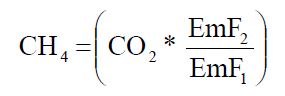
Where:
- CH4
- Annual methane emissions (tonnes CH4/year).
- CO2
- Emission rate of CO2 calculated in paragraphs (i)(1) and (i)(2) of this section, as applicable (tonnes/year).
- EmF1
- Default CO2 emission factor for petroleum coke (97.12 kg CO2/GJ).
- EmF2
- Default CH4 emission factor of 2.8 × 10⁻³ kg CH4/GJ.
Calculate N2O emissions using either unit specific measurement data, a unit-specific emission factor based on a source test of the unit, or Equation 200-29 of this section.
Equation 200-29:
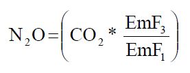
Where:
- N2O
- Annual nitrous oxide emissions (tonnes N2O/year).
- CO2
- Emission rate of CO2 from paragraphs (i)(1) and (i)(2) of this section, as applicable (tonnes/year).
- EmF1
- Default CO2 emission factor for petroleum coke (97 kg CO2/GJ)
- EmF3
- Default N2O emission factor of 5.7 × 10⁻⁴ kg N2O/GJ).
- Uncontrolled Blowdown Systems. For uncontrolled blowdown systems, the person shall use the methods for process vents in paragraph (b) of this section.
- Loading Operations. For crude oil, intermediate, or product loading operations for which the equilibrium vapor-phase concentration of methane is 0.5 volume per cent or more, calculate CH4 emissions from loading operations using product-specific, vapor-phase methane composition data (from measurement data or process knowledge) and the emission estimation procedures provided in Section 5.2 of the AP-42: “Compilation of Air Pollutant Emission Factors, Volume 1: Stationary Point and Area Sources.” For loading operations in which the equilibrium vapor-phase concentration of methane is less than 0.5 volume per cent, the person may assume zero methane emissions.
- Delayed coking units. Calculate the CH4 emissions from the depressurization of the coking unit vessel (i.e., the “coke drum”) to atmosphere using either of the methods provided in paragraphs (m)(1) or (m)(2), provided no water or steam is added to the vessel once it is vented to the atmosphere. The person shall use the method in paragraph (m)(1) of this section if the person adds water or steam to the vessel after it is vented to the atmosphere.
Use the process vent method in paragraph (b) of this section and also calculate the CH4 emissions from the subsequent opening of the vessel for coke cutting operations using Equation 200-30 of this section. If the person has coke drums or vessels of different dimensions, use Equation 200-30 for each set of coke drums or vessels of the same size and sum the resultant emissions across each set of coke drums or vessels to calculate the CH4 emissions for all delayed coking units.
Equation 200-30:
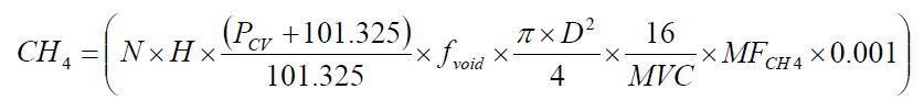
Where:
- CH4
- Annual methane emissions from the delayed coking unit vessel opening (tonnes/year).
- N
- Cumulative number of vessel openings for all delayed coking unit vessels of the same dimensions during the year.
- H
- Height of coking unit vessel (metres).
- PCV
- Gauge pressure of the coking vessel when opened to the atmosphere prior to coke cutting or, if the alternative method provided in paragraph (l)(2) of this section is used, gauge pressure of the coking vessel when depressurization gases are first routed to the atmosphere (kilopascals)
- 101.325
- Assumed atmospheric pressure (kPa)
- fvoid
- Volumetric void fraction of coking vessel prior to steaming based on engineering judgment at reference temperature and pressure conditions as used by the facility (m3 gas/m3 of vessel);
- D
- Diameter of coking unit vessel (metres).
- 16
- Molecular weight of CH4 (kg/kg-mole).
- MVC
- Molar volume conversion factor at the same reference conditions as the cooking vessel (Rm3/kg-mole).
- 8.3145 × [273.16 + reference temperature in °C] ⁄ [reference pressure in kilopascal]
- MFCH4
- Average mole fraction of methane in coking vessel gas based on the analysis of at least two samples per year, collected at least four months apart (kg-mole CH4/kg-mole gas, wet basis);
- 0.001
- Conversion factor from kg to tonne.
- Calculate the CH4 emissions from the depressurization vent and subsequent opening of the vessel for coke cutting operations using Equation 200-30 of this section and the pressure of the coking vessel when the depressurization gases are first routed to the atmosphere. If the person has coke drums or vessels of different dimensions, use Equation 200-30 for each set of coke drums or vessels of the same size and sum the resultant emissions across each set of coke drums or vessels to calculate the CH4 emissions for all delayed coking units.
CAN-CWB(without H2 and cogeneration)
Calculate CAN-CWB(without H2 and cogeneration) using the following steps. This value excludes hydrogen production from Hydrogen Generation units and excludes steam and electricity generation from a cogeneration unit located inside the refinery.
- Calculate the CWBref using the CAN-CWB Methodology for all Standard Refining Process Units, including the hydrogen generated via Hydrogen Generation units, if present. Exclude CAN-CWB adjustments associated with Sales and Exports of steam and electricity resulting from the presence of a cogeneration unit inside the refinery.
- Calculate the Petroleum Refinery ‘direct-only emissions’ including Hydrogen Generation units emissions (reported under ON.132), if that process unit is present. Exclude from these emissions the cogeneration unit emissions, if present inside the refinery.
- Calculate the Petroleum Refinery ‘indirect emissions’ using the CAN-CWB Methodology. Use an emission factor of 0.521 tonnes CO2e per MWh for calculating indirect emissions from electricity obtained from outside the refinery and from a cogeneration unit located inside the refinery. Use an emission factor of 0.0125 tonne CO2e per kBtu/d for calculating indirect emissions from steam imported from outside the refinery and from a cogeneration unit located inside the refinery.
- If a Hydrogen Generation unit is present, calculate the Petroleum Refinery ‘direct-only emissions’ excluding the Hydrogen Generation unit emissions. As per (2) above, exclude from these emissions the cogeneration unit emissions, if present inside the refinery.
- Calculate the Direct Only CAN-CWB(with H2, no Cogen) for the refinery as per the CAN-CWB Methodology using the values from (1), (2) and (3) above.
- Calculate the Direct Only CAN-CWB(without H2 and cogeneration) by multiplying (5) and (4), divided by (2).
ON.204 Sampling, Analysis, and Measurement Requirements
- Catalyst Regeneration.
- For FCCUs and fluid coking units, the person shall measure the following parameters:
- The daily oxygen concentration in the oxygen enriched air stream inlet to the regenerator.
- Continuous measurements of the volumetric flow rate of air and oxygen enriched air entering the regenerator.
- Weekly periodic measurements of the CO2, CO and O2 concentrations in the regenerator exhaust gas (or continuous measurements if the equipment necessary to make continuous measurements is already in place).
- Daily determinations of the carbon content of the coke burned.
- The number of hours of operation.
- The measured daily or weekly values can be used to derive the minute or hourly parameters as required by the corresponding equations.
- For periodic catalyst regeneration, the person shall measure the following parameters.
- The mass of catalyst regenerated in each regeneration cycle.
- The weight fraction of carbon on the catalyst prior to and after catalyst regeneration.
For continuous catalyst regeneration in operations other than FCCUs and fluid cokers, the person shall measure the following parameters.
The hourly catalyst regeneration rate.
- The weight fraction of carbon on the catalyst prior to and after catalyst regeneration.
- The number of hours of operation.
- For FCCUs and fluid coking units, the person shall measure the following parameters:
- Process vents. The person shall measure the following parameters for each process vent.
- The vent flow rate for each venting event from measurement data, process knowledge or engineering estimates.
- The molar fraction of CO2, N2O, and CH4 in the vent gas stream during each venting event from measurement data, process knowledge or engineering estimates.
- The duration of each venting event.
- Asphalt Production. The person shall measure the mass of asphalt blown.
- Sulphur Recovery. The person shall measure the volumetric flow rate of acid gas to the SRU. If using source specific molar fraction that is based on measurements instead of the default factor or engineering estimates, the person shall conduct an annual test of the molar fraction value.
- Flares and Other Control Devices. The person shall measure the following:
- If the person has a continuous flow monitor on the flare, the person shall use the measured flow rates when the monitor is operational and the flow rate is within the calibrated range of the measurement device to calculate the flare gas flow. If the person does not have a continuous flow monitor on the flare and for periods when the monitor is not operational or the flow rate is outside the calibrated range of the measurement device, the person shall use engineering calculations, company records, or similar estimates of volumetric flare gas flow.
- If using the method specified in ON.203(e)(2)(i)(A), monitor the carbon content of the flare gas daily if the flare is already equipped with the necessary measurement devices (at least weekly if not).
- If using the method specified in ON.203(e)(2)(i)(B), monitor the high heat value of the flare gas daily if the flare is already equipped with the necessary measurement devices (at least weekly if not).
- Storage Tanks. The person shall determine the annual throughput of crude oil, naphtha, distillate oil, asphalt, and gas oil for each storage tank using company record or applicable plant instruments.
- Wastewater Treatment. The person shall measure the following parameters.
- The person shall collect samples representing wastewater influent to the anaerobic wastewater treatment process, following all preliminary and primary treatment steps (e.g., after grit removal, primary clarification, oil-water separation, dissolved air flotation, or similar solids and oil separation processes). The person shall collect and analyze samples for COD or BOD5 concentration once each calendar week.
- The person shall measure the flow rate of wastewater entering anaerobic wastewater treatment process once each calendar week. The flow measurement location shall correspond to the location used to collect samples analyzed for COD or BOD5 concentration.
- The quarterly nitrogen content of the wastewater.
- Oil-Water Separators. The person shall measure the daily volume of waste water treated by the oil-water separators.
- Petroleum Coke Calcining. Determine the mass of petroleum coke as required using measurement equipment used for accounting purposes including purchase records or direct measurement. Determine the carbon content of petroleum coke as using any one of the following methods.
- ASTM D3176.
- ASTM D5291.
- ASTM D5373.
- Any of the other analytical methods listed in the Technical Reference Document section of this Guideline (section 5).
- The most appropriate method published by a consensus-based standards organization If no appropriate method is published by a consensus-based standards organization, use industry standard methods, noting where such methods are used and what methods are used.
- CAN-CWB. Determine the following parameters through measurements.
- “Throughput” for each of the Standard Refining Process Units identified in Appendix B of the CAN-CWB Methodology.
- “Total Input Barrels” described in Section 2.4.2 of the CAN-CWB Methodology.
- “Non-Crude Input Barrels” described in Section 2.4.3 of the CAN-CWB Methodology.
- “Exported Steam” from the refinery, net of steam originating from a cogeneration unit located inside the refinery.
- “Exported Electricity” from the refinery, net of electricity originating from a cogeneration unit located inside the refinery.
- “Imported steam” to the refinery, including steam originating from a cogeneration unit located inside the refinery.
- “Imported Electricity” to the refinery, including electricity originating from an outside source or from a cogeneration unit located inside the refinery.
- Equipment used to measure the CAN-CWB parameters shall be:
- calibrated according to the manufacturer’s instructions and
- maintained to achieve an accuracy of plus or minus 5%.
ON.205 Procedures for Estimating Missing Data
Unavailable analytical Data
- Whenever analytical data relating to sampling is unavailable, the person shall, using the methods prescribed in ON.204, re-analyze the original sample, a backup sample or a replacement sample for the same measurement and sampling period.
Determination of quantity
- Whenever sampling and measurement data required by ON.204 for the calculation of emissions is missing the person shall ensure that the data is replaced using the following missing data procedures:
- When the missing data concerns carbon content, temperature, pressure or gas concentration, the person shall:
Determine the sampling or measurement rate using the following Equation 200-31:
Equation 200-31:
R = QSAct ⁄ QSRequired
Where:
- When the missing data concerns carbon content, temperature, pressure or gas concentration, the person shall:
- R
- Sampling or measurement rate that was used, expressed as a percentage
- QSAct
- Quantity of actual samples or measurements obtained by the person
- QSRequired
- Quantity of samples or measurements required under ON.204
- Replace the missing data as follows,
- If R ≥ 0.9: replace the missing data by the arithmetic mean of the sampling or measurement data from immediately before and after the missing data period. If no data is available from before the missing data period, the person shall use the first available data from after the missing data period;
- If 0.75 ≤ R < 0.9: replace the missing data by the highest data value sampled or analyzed during the reporting period for which the calculation is made;
- If R < 0.75: replace the missing data by the highest data value sampled or analyzed during the 3 preceding years;
- When the missing data concerns coke burn, volumetric gas flow, gas volume, number of hours of operation, quantity of bituminous product blown, quantity of crude oil and intermediate products, quantity of wastewater treated, quantity of coke, quantity of coke dust or number of vessels openings in a coking unit, the replacement data shall be generated from best estimates based on all of the data relating to the processes.
- For all units subject to the requirements of ON.20 that monitor and report emissions using a CEMS, the missing data backfilling procedures in EPS 1/PG/7 shall be followed for CO2 concentration, stack gas flow rate, fuel flow rate, high heating value, and fuel carbon content.
| (kg min)/(hr dRm³%) | (lb min)/(hr dscf %) | |
|---|---|---|
| K1: Carbon burn term | 0.2982 | 0.0186 |
| K2: Hydrogen burn term from O2 in Air | 2.088 | 0.1303 |
| K3: Hydrogen burn equivalent in excess O2 and carbon oxides | 0.0994 | 0.0062 |
| Type of Treatment and Discharge Pathway or System | Comments | MCF | Range |
|---|---|---|---|
| Sea, river and lake discharge | Untreated, rivers with high organic loading may turn anaerobic, however this is not considered here | 0.1 | 0 - 0.2 |
| Aerobic treatment plant | Treated, well maintained, some CH4 may be emitted from settling basins | 0 | 0 - 0.1 |
| Aerobic treatment plant | Treated, not well maintained, overloaded | 0.3 | 0.2 - 0.4 |
| Anaerobic digester for sludge | Treated, CH4 recovery not considered here | 0.8 | 0.8 - 1.0 |
| Anaerobic reactor | Treated, CH4 recovery not considered here | 0.8 | 0.8 - 1.0 |
| Anaerobic shallow lagoon | Treated, depth less than 2 metres | 0.2 | 0 - 0.3 |
| Anaerobic deep lagoon | Treated, depth more than 2 metres | 0.8 | 0.8 - 1.0 |
For CH4 generation capacity (B) in kg CH4/kg COD, use default factor of 0.25 kg CH4/kg COD.
The emission factor for N2O from discharged wastewater (EFN2O) is 0.005 kg N2O-N/kg-N.
- MCF
- methane conversion factor (the fraction of waste treated anaerobically).
- COD
- chemical oxygen demand (kg COD/m3).
| Separator Type | Emission factor (EFsep)a kg NMHC/m3 wastewater treated |
|---|---|
| Gravity type – uncovered | 1.11e-01 |
| Gravity type – covered | 3.30e-03 |
| Gravity type – covered and connected to destruction device | 0 |
| DAFb of IAFc – uncovered | 4.00e-03d |
| DAF or IAF – covered | 1.20e-04d |
| DAF or IAF – covered and connected to a destruction device | 0 |
a EFs do not include ethane
b DAF = dissolved air flotation type
c IAF = induced air flotation device
d EFs for these types of separators apply where they are installed as secondary treatment systems
ON.340 Phosphoric acid Production
ON.341 Activity Definition
For the purposes of this standard quantification method:
- Phosphoric acid production
- has the same meaning as in the Regulation.
- Person
- means a person that engages in phosphoric acid production.
ON.342 Greenhouse Gas Reporting Requirements
A person shall set out the following information, calculated for the calendar year using standard quantification methods ON.340 – ON.345, in an emission report prepared for a calendar year in respect of phosphoric acid production at a facility:
- CO2 process emissions from each wet-process phosphoric acid process line (tonnes).
- Annual phosphoric acid production (tonnes)
ON.343 Calculation of GHG Emissions
Quantify emissions in accordance with US EPA 40 CFR 98 Subpart Z Section 98.263.
ON.344 Sampling, Analysis, and Measurement Requirements
Sampling, analysis and measurement requirements for this activity shall be done in accordance with US EPA 40 CFR 98 Subpart Z Section 98.264.
ON.345 Procedures for Estimating Missing Data
Missing data requirements for this activity shall be estimated in accordance with US EPA 40 CFR 98 Subpart Z Section 98.265.
ON.70 Primary Aluminum Production
ON.71 Activity Definition
For the purposes of this standard quantification method:
- Primary aluminum production
- has the same meaning as in the Regulation.
- Person
- means a person that engages in primary aluminum production.
ON.72 Greenhouse Gas Reporting Requirements
A person shall set out the following information, calculated for the calendar year using standard quantification methods ON.70 – ON.75, in an emission report prepared for a calendar year in respect of primary aluminum production at a facility:
- Perfluoromethane (CF4), and perfluoroethane (C2F6) emissions from anode effects in all prebake and Søderberg electrolysis cells (tones).
- CO2 emissions from anode consumption during electrolysis in all prebake and Søderberg electrolysis cells (tonnes).
- CO2 emissions from on-site anode baking (tonnes).
- Annual aluminum production (tonnes)
ON.73 Calculation of GHG Emissions
Quantify emissions in accordance with US EPA 40 CFR 98 Subpart F Section 98.63.
ON.74 Sampling, Analysis, and Measurement Requirements
Sampling, analysis and measurement requirements for this activity shall be done in accordance with US EPA 40 CFR 98 Subpart F Section 98.64.
ON.75 Procedures for Estimating Missing Data
Missing data requirements for this activity shall be estimated in accordance with US EPA 40 CFR 98 Subpart F Section 98.65.
ON.210 Pulp and Paper Production
ON.211 Activity Definition
For the purposes of this standard quantification method:
- Pulp and paper production
- has the same meaning as in the Regulation.
- Person
- means a person that engages in pulp and paper production.
ON.212 Greenhouse Gas Reporting Requirements
A person shall set out the following information, calculated for the calendar year using standard quantification methods ON.210 – ON.215, in an emission report prepared for a calendar year in respect of pulp and paper production at a facility:
- Annual CO2, biogenic CO2, CH4, and N2O process emissions from all recovery units and kilns combined in tonnes, as specified in ON.213.
- Annual CO2 emissions from addition of makeup chemicals (CaCO3, Na2CO3) in the chemical recovery areas of chemical pulp mills.
- Annual consumption of carbonate in tonnes.
- Annual black liquor production in tonnes.
- Annual pulp production in tonnes air dried pulp.
ON.213 Calculation of GHG Emissions
Calculate emissions from each unit (i.e., kraft or soda chemical recovery furnace, sulfite chemical recovery combustion unit, stand-alone semichemical recovery combustion unit, or kraft or soda pulp mill lime kiln) as specified under paragraphs (a) through (d) of this section. CH4 and N2O emissions shall be calculated as the sum of emissions from combustion of fossil fuels and combustion of biomass in spent liquor solids.
- For kraft or soda pulp mill lime kilns, calculate fossil-fuel based CO2 emissions from direct measurement of fossil fuels consumed and the methodology for stationary combustion sources specified by ON.20.
- For kraft or soda pulp mill lime kilns, calculate fossil-fuel based CH4 and N2O emissions from direct measurement of fossil fuels consumed, default HHV, and default emission factors according to the methodology specified by ON.20.
- Calculate biogenic CO2 emissions and emissions of CH4 and N2O from biomass as specified under subparagraphs (1) through (3).
For kraft or soda chemical recovery furnaces, calculate emissions using Equation 210-1:
Equation 210-1:
Emissions = Solids × HHV × EF
Where:
- Emissions
- Biogenic CO2 emissions and emissions of CH4 and N2O from biomass (spent liquor solids) combustion (tonnes/year).
- Solids
- Mass of spent liquor solids combusted (tonnes/year).
- HHV
- Annual high heat value of spent liquor solids (mmBtu/kg).
- EF
- Default emission factor for CO2, CH4, and N2O from Table 210-1 (kg/mmBtu)
For sulfite or stand-alone semi-chemical or chemical recovery combustion units, calculate CO2 emissions using Equation 210-2:
Equation 210-2:
ECO2 = 3.664 × Solids × CC
Where:
- ECO2
- Biogenic CO2 emissions from spent liquor solids combustion (tonnes/year).
- 3.664
- Ratio of molecular weights, CO2 to carbon.
- Solids
- Mass of spent liquor solids combusted (tonnes/year).
- CC
- Annual carbon content of spent liquor solids (per cent by weight, expressed as a decimal fraction).
- For sulfite or stand-alone semi-chemical or chemical recovery combustion units, calculate emissions of CH4 and N2O from biomass using Equation 210-1.
For make-up chemical use, calculate CO2 emissions by using direct or indirect measurement of the quantity of chemicals added and ratios of the molecular weights of CO2 and make-up chemicals using Equation 210-3:
Equation 210-3:
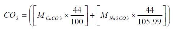
Where:
- CO2
- CO2 emissions from make-up chemicals (tonnes/year).
- MCaCO3
- Make-up quantity of CaCO3 used for calendar year (tonnes/year).
- MNa2CO3
- Make-up quantity of Na2CO3 used for calendar year (tonnes/year).
- 44
- Molecular weight of CO2.
- 100
- Molecular weight of CaCO3.
- 106
- Molecular weight of Na2CO3.
ON.214 Sampling, Analysis, and Measurement Requirements
At least annually, determine the high heat value, annual mass and carbon content of spent liquor solids using any of the following methods. If measurements are performed more frequently than annually, then fuel properties shall be based on the average of the representative measurements made during the year.
- Determine high heat values of black liquor using Technical Association of the Pulp and Paper Industry (TAPPI) T684 om-06 “Gross High Heating Value of Black Liquor”.
- Determine annual mass of spent liquor solids using one of the methods specified in subparagraph (1) or (2).
- Measure mass of annual spent liquor solids using TAPPI T650 om-05 “Solids Content of Black Liquor”.
- Determine mass of annual spent liquor solids based on records of measurements made with an online measurement system that determines the mass of spent liquor solids fired in a chemical recovery furnace or chemical recovery combustion unit. Measure the quantity of black liquor produced each month.
- Determine carbon content using one of the following methods:
- ASTM D5373;
- ASTM 5291;
- Any of the other analytical methods listed in the Technical Reference Document section of this Guideline (section 5);
- The most appropriate method published by a consensus-based standards organization; or
- If no appropriate method is published by a consensus-based standards organization, use industry standard methods, noting where such methods are used and what methods are used.
ON.215 Procedures for Estimating Missing Data
Unavailable analytical Data
- Whenever analytical data relating to sampling is unavailable, the person shall, using the methods prescribed in ON.214, re-analyze the original sample, a backup sample or a replacement sample for the same measurement and sampling period.
Determination of quantity
- Whenever sampling and measurement data required by ON.214 for the calculation of emissions is missing the person shall ensure that the data is replaced using the following missing data procedures:
- When the missing data concerns carbon content, temperature, pressure or gas concentration, the person shall:
Determine the sampling or measurement rate using the following Equation 214-4:
Equation 214-4:
R = QSAct ⁄ QSRequiredWhere:
- When the missing data concerns carbon content, temperature, pressure or gas concentration, the person shall:
- R
- Sampling or measurement rate that was used, expressed as a percentage
- QSAct
- Quantity of actual samples or measurements obtained by the person
- QSRequired
- Quantity of samples or measurements required under ON.214
- Replace the missing data as follows,
- If R ≥ 0.9: replace the missing data by the arithmetic mean of the sampling or measurement data from immediately before and after the missing data period. If no data is available from before the missing data period, the person shall use the first available data from after the missing data period;
- If 0.75 ≤ R < 0.9: replace the missing data by the highest data value sampled or analyzed during the reporting period for which the calculation is made;
- If R < 0.75: replace the missing data by the highest data value sampled or analyzed during the 3 preceding years;
- When the missing data concerns the quantity of spent pulping liquor, the mass flow of spent pulping liquor, the annual production of each pulp and paper product manufactured or the quantity of carbonate material, the replacement data shall be estimated on the basis of all the data relating to the processes used.
- For all units subject to the requirements of ON.20 that monitor and report emissions using a CEMS, the missing data backfilling procedures in EPS 1/PG/7 shall be followed for CO2 concentration, stack gas flow rate, fuel flow rate, high heating value, and fuel carbon content.
| Wood Furnish | CO2a | CH4 | N2O |
|---|---|---|---|
| North American Softwood | 94.4 | 0.030 | 0.005 |
| North American Hardwood | 93.7 | 0.030 | 0.005 |
| Bagasse | 95.5 | 0.030 | 0.005 |
| Bamboo | 93.7 | 0.030 | 0.005 |
| Straw | 95.1 | 0.030 | 0.005 |
a Includes emissions from both the recovery furnace and pulp mill lime kiln.
ON.30 Refinery Fuel Gas Use within a Petroleum Refinery
ON.31 Activity Definition
For the purposes of this standard quantification method:
- Refinery fuel gas use
- has the same meaning as in the Regulation.
- Person
- means a person that engages in refinery fuel gas use.
ON.32 Greenhouse Gas Reporting Requirements
A person shall set out the following information, calculated for the calendar year using standard quantification methods ON.30 – ON.35, in an emission report prepared for a calendar year in respect of refinery fuel gas use within a petroleum refinery at a facility:
- Annual CO2, CH4, and N2O emissions from refinery fuel gas combustion in tonnes.
- Annual fuel consumption in units of standard cubic meters.
- Average carbon content of each fuel used to compute CO2 emissions.
ON.33 Calculation of Greenhouse Gas Emissions
- Calculation of CO2 Emissions. The person shall calculate daily CO2 emissions for each fuel gas system using any of the methods specified in paragraphs (a)(1) through (a)(4) of this section. Calculate the total annual CO2 emissions from combustion of all fuel gas by summing the CO2 emissions from each fuel gas system.
- Use a CEMS that complies with the provisions in Calculation Methodology 4 of ON.23.
Calculate CO2 emissions from each refinery fuel gas system and flexigas system using measured carbon content and molecular weight of the gas and Equation 30-1:
Equation 30-1:
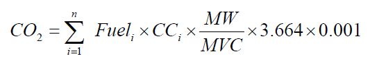
Where:
- CO2
- Carbon dioxide emissions, tonnes/year.
- Fueli
- Daily refinery fuel or flexigas combusted (Rm3) at reference temperature and pressure conditions as used by the facility. If a mass flow meter is used, measure the daily fuel combusted in kg and replace the term “MW⁄MVC” with “1”.
- CCi
- Daily sample of carbon content of the fuel (kg C/kg fuel).
- MW
- Daily sample of molecular weight of fuel (kg/kg-mole).
- MVC
- Molar volume conversion factor at the same reference conditions as the above Fueli (Rm3/kg-mole).
- 8.3145 × [273.16 + reference temperature in °C] ⁄ [reference pressure in kilopascal].
- 3.664
- Ratio of molecular weights, carbon dioxide to carbon.
- 0.001
- Conversion factor for kg to tonnes.
- n
- Number of days in a year.
- For associated gas, low heat content gas, or other fossil fuels; follow the requirements for general stationary combustion in Calculation Methodologies 3 or 4 of ON.23, as appropriate for each fuel.
- Where individual fuels are mixed prior to combustion, the person may choose to calculate CO2 emissions for each fuel prior to mixing instead of using the methods in paragraphs (a)(1) or (a)(2) of this section. In this case, the person shall determine the fuel flow rate and appropriate fuel specific parameters (e.g. carbon content, HHV) of each fuel stream prior to mixing, calculate CO2 emissions for each fuel stream, and sum the emissions of the individual fuel streams to determine total CO2 emissions from the mixture. CO2 emissions for each fuel stream shall be estimated using the following methods:
- For natural gas and associated gas, use the appropriate methodology specified in Calculation Methodologies 2 or 3 of ON.23.
- For refinery fuel gas, flexigas, and low heat content gas, use the methodology in paragraph (a)(2) of this section.
- Calculation of CH4 and N2O Emissions. The person shall use the methods specified in section ON.24 to calculate the annual CH4 and N2O emissions.
ON.34 Sampling, Analysis, and Measurement Requirements
- Measure the fuel consumption rate daily using methods specified in ON.25(b).
- Daily sampling and analysis to determine the carbon content and molecular weight of the fuel is required if there is sampling at a frequency of daily or more currently or if there is online instruments in place to monitor carbon content. Otherwise, weekly sampling and analysis of carbon content and molecular weight shall be performed. The equipment necessary to perform daily sampling and analysis of carbon content and molecular weight for refinery fuel gas shall be installed no later than January 1, 2012
Measure the carbon content for fuel gas and flexigas using either ASTM D1945 or ASTM D1946, or any of the other analytical methods listed in the Technical Reference Document section of this Guideline (section 5), or the most appropriate method published by a consensus-based standards organization. If no appropriate method is published by a consensus-based standards organization, use industry standard methods, noting where such methods are used and what methods are used.
Alternatively, the results of chromatographic analysis of the fuel gas may be used, provided that the gas chromatograph is operated, maintained, and calibrated according to the manufacturer’s instructions; and the methods used for operation, maintenance, and calibration of the gas chromatograph are documented in a plan.
ON.35 Procedures for Estimating Missing Data
Unavailable analytical Data
- Whenever analytical data relating to sampling is unavailable, the person shall, using the methods prescribed in ON.34, re-analyze the original sample, a backup sample or a replacement sample for the same measurement and sampling period.
Determination of quantity
- Whenever sampling and measurement data required by ON.34 for the calculation of emissions is missing the person shall ensure that the data is replaced using the following missing data procedures:
- When the missing data concerns carbon content, temperature, pressure or gas concentration, the person shall:
Determine the sampling or measurement rate using the following Equation 30-2:
Equation 30-2:
R = QSAct ⁄ QSRequiredWhere:
- When the missing data concerns carbon content, temperature, pressure or gas concentration, the person shall:
- R
- Sampling or measurement rate that was used, expressed as a percentage
- QSAct
- Quantity of actual samples or measurements obtained by the person
- QSRequired
- Quantity of samples or measurements required under ON.34
- Replace the missing data as follows,
- If R ≥ 0.9: replace the missing data by the arithmetic mean of the sampling or measurement data from immediately before and after the missing data period. If no data is available from before the missing data period, the person shall use the first available data from after the missing data period;
- If 0.75 ≤ R < 0.9: replace the missing data by the highest data value sampled or analyzed during the reporting period for which the calculation is made;
- If R < 0.75: replace the missing data by the highest data value sampled or analyzed during the 3 preceding years;
- When the missing data concerns gas consumption, the replacement data shall be generated from best estimates based on all of the data relating to the processes.
- For all units subject to the requirements of ON.20 that monitor and report emissions using a CEMS, the missing data backfilling procedures in EPS 1/PG/7 shall be followed for CO2 concentration, stack gas flow rate, fuel flow rate, high heating value, and fuel carbon content.
ON.220 Soda Ash Production
ON.221 Activity Definition
For the purposes of this standard quantification method:
- Soda ash production
- has the same meaning as in the Regulation.
- Person
- means a person that engages in soda ash production.
ON.222 Greenhouse Gas Reporting Requirements
A person shall set out the following information, calculated for the calendar year using standard quantification methods ON.220 – ON.225, in an emission report prepared for a calendar year in respect of soda ash production at a facility:
- CO2 process emissions from soda ash manufacturing line (tonnes).
- Annual soda ash production (tonnes)
ON.223 Calculation of GHG Emissions
Quantify emissions in accordance with EPA 40 CFR part 98.293.
ON.224 Sampling, Analysis, and Measurement Requirements
Sampling, analysis and measurement requirements for this activity shall be done in accordance with US EPA 40 CFR 98 Subpart CC Section 98.294.
ON.225 Procedures for Estimating Missing Data
Missing data requirements for this activity shall be estimated in accordance with US EPA 40 CFR 98 Subpart CC Section 98.295.
ON.240 Zinc Production
ON.241 Activity Definition
For the purposes of this standard quantification method:
- Zinc production
- has the same meaning as in the Regulation.
- Person
- means a person that engages in zinc production.
ON.242 Greenhouse Gas Reporting Requirements
A person shall set out the following information, calculated for the calendar year using standard quantification methods ON.240 – ON.245, in an emission report prepared for a calendar year in respect of zinc production at a facility:
- Annual emissions of CO2 at the facility level (tonnes).
- Annual quantities of each carbon-containing input material used (tonnes).
- Carbon content of each carbon-containing input material used (tonnes C/tonne reducing agent).
- Inferred waste-based carbon-containing material emission factor (if waste-based reducing agent quantification method used).
- Annual zinc production (tonnes)
ON.243 Calculation of CO2 Emissions
Calculate total CO2 emissions as specified under paragraph (a) or (b) of this section.
- Determine facility CO2 emissions using continuous emissions monitoring systems (CEMS) as specified in Calculation Methodology 4 of ON.23.
Calculate total CO2 emissions using Equation 240-1. Specific materials that contribute less than 1 per cent of the total carbon into the process do not have to be included in the calculation using Equation 240-1:
Equation 240-1:
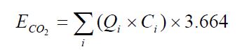
Where:
- ECO2
- Annual CO2 emissions from carbon-containing materials (tonnes);
- Qi
- Annual quantity of carbon-containing material i (tonnes);
- Ci
- Carbon content of carbon-containing material i (tonnes C/tonne process input);
- 3.664
- Stoichiometric conversion factor from C to CO2.
ON.244 Sampling, Analysis, and Measurement Requirements
The annual mass of each solid carbon-containing input material consumed shall be determined using facility instruments, procedures, or records used for accounting purposes, including either direct measurement of the quantity of the material consumed or by calculations using process operating information.
The average carbon content of each material consumed shall be determined as specified under paragraph (a) or (b) of this section.
- Obtain carbon content by collecting and analyzing at least three representative samples of the material each year using one of the following methods, or any of the other analytical methods listed in the Technical Reference Document section of this Guideline (section 5), or the most appropriate method published by a consensus-based standards organization. If no appropriate method is published by a consensus-based standards organization, use industry standard methods, noting where such methods are used and what methods are used.
- For zinc-bearing materials, use ASTM E1941.
- For carbonaceous reducing agents and carbon electrodes, use ASTM D5373.
- For flux materials (i.e., limestone or dolomite), use ASTM C25.
- For waste-based carbon-containing material, determine carbon content by operating the smelting furnace both with and without the waste-reducing agents while keeping the composition of other material introduced constant.
- Use an average carbon content value from samples analyzed for per cent carbon, based on monthly composites of e-waste that is riffled, ground to no less than 2 mm, split and then analyzed.
- Obtain carbon content from material vendor or supplier.
- The person shall measure the zinc production. Equipment used to measure the production shall be:
- calibrated according to the manufacturer’s instructions and
- maintained an accuracy of plus or minus 5%.
ON.245 Procedures for Estimating Missing Data
Unavailable analytical Data
- Whenever analytical data relating to sampling is unavailable, the person shall, using the methods prescribed in ON.244, re-analyze the original sample, a backup sample or a replacement sample for the same measurement and sampling period.
Determination of quantity
- Whenever sampling and measurement data required by ON.244 for the calculation of emissions is missing the person shall ensure that the data is replaced using the following missing data procedures:
- When the missing data concerns carbon content, temperature, pressure or gas concentration, the person shall:
Determine the sampling or measurement rate using the following Equation 240-2:
Equation 240-2:
R = QSAct ⁄ QSRequiredWhere:
- When the missing data concerns carbon content, temperature, pressure or gas concentration, the person shall:
- R
- Sampling or measurement rate that was used, expressed as a percentage
- QSAct
- Quantity of actual samples or measurements obtained by the person
- QSRequired
- Quantity of samples or measurements required under ON.244
- Replace the missing data as follows,
- If R ≥ 0.9: replace the missing data by the arithmetic mean of the sampling or measurement data from immediately before and after the missing data period. If no data is available from before the missing data period, the person shall use the first available data from after the missing data period;
- If 0.75 ≤ R < 0.9: replace the missing data by the highest data value sampled or analyzed during the reporting period for which the calculation is made;
- If R < 0.75: replace the missing data by the highest data value sampled or analyzed during the 3 preceding years;
- When the missing data concerns raw material consumption, zinc production or by-product production, the replacement data shall be generated from best estimates based on all of the data relating to the processes.
- For all units subject to the requirements of ON.20 that monitor and report emissions using a CEMS, the missing data backfilling procedures in EPS 1/PG/7 shall be followed for CO2 concentration, stack gas flow rate, fuel flow rate, high heating value, and fuel carbon content.
1 If the pump is operating at less than five strokes per minute, this equation is not applicable and the mean bleed rate or volume of chemical equation should be used instead.
* person may use component-specific emission factors quantified using ON.354(a)(3) or (a)(4) during leak detection surveys.
** facility-specific emission factors may be developed based on leak rates quantified, following ON.354(3) or (4), during leak detection surveys or those emission factors calculated for the purposes of ON.356 – Directions for the use of Tables 350-1 to 350-5.