Air Supply Subsystem
Air brake systems are made up of several subsystems. This chapter explains the operation and function of the air-supply subsystem, which produces, stores and manages the compressed air used by the brake system.
Note: There is a circuit diagram of the air-supply subsystem here.
Air compressor
An air compressor produces air for the brake system. Powered by the vehicle’s engine, the air compressor draws in air at normal pressure and forces it into a much smaller space, causing the pressure of the air to increase. This compressed air is a form of stored energy.
Air pressure is usually measured in kiloPascals (kPa) or pounds per square inch (psi). The normal pressure range of an air brake system is determined by the points where the air compressor is turned on (cut-in pressure) and turned off (cut-out pressure).
Note: Cut-out pressure is normally 138 to 173 kPa (20 to 25 psi) above the cut-in pressure. Normal air brake system pressure range is around 690 to 828 kPa (100 to 120 psi). Drivers should know the normal pressure range of the vehicle they operate and should report any abnormal condition. Abnormal pressure readings should always be verified by a technician using an accurate gauge. The actual air brake system pressure range must never be lower than 552 kPa (80 psi) or higher than 1000 kPa (145 psi).
Air compressors are generally powered directly by the vehicle’s engine or by using belts and pulleys and can be mounted either directly on the engine or by brackets and fasteners. The brackets and fasteners must be kept secure so that the air compressor can work properly. All components used to attach and power the air compressor must be kept in good condition to ensure a constant supply of compressed air.
Governor
Air compressors are designed to run whenever the engine is running. As a result, they are able to produce much more air than is needed by the brake system. To prevent the compressor from producing too much compressed air and to reduce the load on the engine, a governor is used in the air brake system. When air-pressure is high enough in the system, the governor causes the compressor to stop pumping air (cut-out). When the air-pressure drops to a certain point, the governor will cause the compressor to start pumping air again (cut-in).
Normal pressure range
The normal pressure range of an air brake system is determined by the cut-in and cut-out pressures. Cut-out pressure is normally 138 to 173 kPa (20 to 25 psi) above the cut-in pressure (See Diagram 2-1).
Cut-out and cut-in pressures should remain within the range specified by the vehicle manufacturer, and any change in these pressures, should be reported. Actual cut-out pressure must never be higher than 1000 kPa (145 psi). Actual cut-in pressure must never be less than 552 kPa (80 psi).
Important: A vehicle should only be driven when air pressure is in the normal operating range. A drop in air pressure below the normal cut-in setting is a sign that the air brake system is malfunctioning or that an abnormal demand is being placed on the system. Bring the vehicle to a safe stop as soon as possible. Proceed only when air pressure returns to its normal operating range and all other air brake system functions are normal.
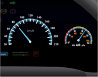
Diagram 2-1: Air pressure gauge
Air tanks
Air tanks Air from the compressor is stored in air tanks. Located under or around the frame of the vehicle, these tanks are usually made of steel and shaped like cylinders with domed ends. One, two, three or more tanks may be used, depending on the specific needs of the vehicle. In some cases, two tanks are housed within one cylinder using an internal separator that is not visible from the outside.
The air that is drawn in by the air compressor contains moisture or humidity. As the air is compressed and passed into the tanks, the moisture condenses or “drops out” of the air and settles to the bottom of the tank. Oil used to lubricate the air compressor may also mix with the air that passes through the compressor and settle at the bottom of the tank.
Supply or "wet" tank
The first tank that the compressed air enters is called the supply tank. Since it collects most of the moisture and oil that drops out of the air, it is also called a “wet” tank. If the mixture of moisture and oil that collects in the supply tank passes into the rest of the air brake system, it can damage brake components and interfere with the operation of the system. The following are some of the problems that can occur.
- The collected moisture and oil mixture can form a sludge that can pass from the tank into other components of the air brake system, damaging seals and causing brake valves to stick.
- The mixture of moisture and oil can become corrosive and damage the Air-tank and other system components.
- Moisture in the brake system can freeze in cold temperatures and may cause brake failure.
- Too much moisture and oil collecting in the Air-tanks can reduce the volume of air and may cause brake failure.
Air-tank drain valve
Moisture and oil must be drained from the tanks on a regular basis. Many vehicle manufacturers recommend that the vehicle’s air-tanks be drained daily. This is done through the air-tank drain valve, located at the bottom of each air-tank (See Diagram 2-2). Remember to check each tank to be sure it is fully drained and watch for anything abnormal about the discharge from the tank. When draining the tanks, the supply tank should always be drained first to prevent accumulated moisture flowing into the next tank being drained. When the supply tank is drained first, any accumulated moisture is removed before it can pass further into the system.
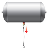
Diagram 2-2: Air tank and drain valve
One-way check valve
When air flows out of the supply tank, it is prevented from returning by one-way check valves.
Dual-service (primary and secondary) tanks
When air leaves the supply tank, it splits into two circuits, passing into primary and secondary air tanks called dual-service tanks. These are also called “dry” tanks because they collect less moisture than the supply or “wet” tank. Having two delivery circuits is a safety feature that ensures if one circuit fails, the other circuit will provide enough brake function to stop the vehicle. The two circuits are referred to as the primary circuit and the secondary circuit.
Air dryer
Vehicles may use an air dryer to reduce the amount of moisture that passes into the air brake system. An air dryer is located between the air compressor and the supply tank. Air that is pumped by the air compressor passes through the air dryer where it cools and passes through a drying material. This removes moisture from the air before it enters the supply tank. Moisture collected in the air dryer is expelled with high-pressure air when the compressor reaches cut-out pressure.
Vehicles using air dryers must still have the air tanks drained regularly.
Alcohol evaporator
In cold climates, moisture in the air brake system can freeze and may cause brake failure. Even tiny ice particles can cause problems. An alcohol evaporator adds an alcohol vapor to the air that will mix with any moisture or ice present and reduce its tendency to freeze. Only products specifically designed for this use may be put into an alcohol evaporator.
Air pressure gauge
All vehicles equipped with air brakes must have air pressure gauges that work. Located on the vehicle’s instrument panel, the air pressure gauges let you know how much air pressure is in the air brake system to ensure the system is operating normally. Vehicles may use two separate gauges that show primary and secondary air-tank pressure (See Diagram 2-3) or they may be combined in one gauge with two needles. Labelling of air pressure gauges varies, and some vehicles have additional air pressure gauges for other systems. Gauges may use metric (kPa) or imperial (psi) measurements on their displays.
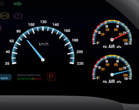
Diagram 2-3: Air pressure gauges showing primary and secondary tank pressure.
Safety valve
The supply tank and air dryer (if present) usually have safety valves to prevent over-pressure of the system. If the governor fails to signal the compressor to cut-out and too much pressure builds up, the safety valves will open to allow the excess air pressure to escape. Safety valves normally open at 1035 kPa (150 psi).
Important: A safety valve that is venting air means there is too much pressure building in the system, requiring immediate repair.
Low air-pressure warning devices
When air pressure in either the primary or secondary tank falls below the minimum amount required to bring the vehicle to a safe stop, a warning device on the instrument panel will alert the driver to the danger (See Diagram 2-4). The warning device must activate before pressure in either tank falls to 380 kPa (55 psi), although most warning devices activate at 414 kPa (60 psi) or even higher. Low air-pressure warning devices must give a visual warning such as a light and may also use a warning buzzer, bell or alarm.
Some vehicles have a warning device called a wig wag. When air-pressure is too low, the arm drops into the driver’s view.
Important: A low air-pressure warning means there is a serious air brake system safety hazard. Bring your vehicle to a safe stop as soon as possible.
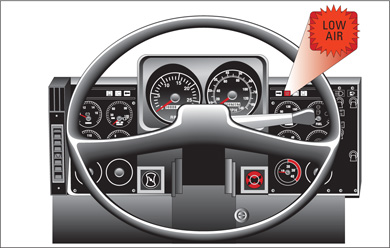
Diagram 2-4: Low air-pressure warning device
Compressed air can be hazardous
It is important to know that the compressed air that is used in air brake systems can be hazardous if you get near it when it is being exhausted from the vehicle. Compressed air leaving the vehicle travels at a very high speed and will carry moisture, oil, dirt and dust. This can be harmful to the eyes and hearing of anyone in its direct path. Dust, dirt, debris or moisture will spray back up from the ground when the compressed air hits it.
To avoid being in the direct path of air exhausting from the air brake system, you should be familiar with all the places where the compressed air exhausts. These include:
- exhaust ports of brake valves,
- on or near the vehicle’s axles,
- air-dryer exhaust port, and
- air-tank drain valves when tanks are being drained.
Never attempt to dismantle, remove, repair or tamper with any brake system component.
Key points to remember
- Compressed air is a form of stored energy that can be hazardous.
- Air compressors compress air by forcing it into a smaller space.
- Air compressors are powered directly by the engine or by using belts and pulleys.
- Air compressors are mounted directly on the engine or by brackets and fasteners.
- The governor controls the air compressor cut-in and cut-out pressure.
- The operating pressure range for vehicle air brake systems must be between 552 kPa and 1000 kPa (80 psi and 145 psi).
- It is unsafe to drive a vehicle when the air pressure is outside the normal operating range.
- Compressed air is stored in the vehicle’s supply or "wet" tank and the dual service (primary and secondary) air tanks.
- To prevent too much moisture and oil from collecting, the air tanks must be drained regularly.
- Air pressure gauges indicate air pressure in the vehicle’s dual service (primary and secondary) air tanks.
- Safety valves prevent over-pressure of the air brake system.
- Low air pressure warning devices give drivers a visual, and sometimes audible, warning that air-pressure is dangerously low.
- An air dryer removes moisture from the air brake system and expels it when the compressor reaches cut-out pressure.
- An alcohol evaporator adds alcohol vapor to the air brake system to help prevent moisture in the system from freezing.