Service Brake Subsystem
Vehicles with air brakes must have separate brake systems for normal stopping and for parking and emergency braking. These systems are controlled independently. The brakes that are used for normal stopping are called service brakes. This chapter explains the operation and function of the service brake subsystem.
Note: There are circuit diagrams showing service brake system components here.
Brake pedal operation
Pressing the brake pedal operates the brakes used for normal stopping. The brake pedal controls the air pressure applied to the service brakes. As the pedal is pressed downward, compressed air passes through a valve attached to the brake pedal and is delivered to the brakes at the wheels. As the brake pedal is pressed harder, the valve opens farther, delivering higher air pressure to the service brakes and increasing the braking force at the wheels.
Since most brake-system designs use dual circuits, air is drawn from both the primary and secondary tanks and is directed to specific wheels on the vehicle. The wheels that receive air through the primary or secondary circuits vary, depending on the vehicle manufacturer. The dual-circuit design means that if one circuit fails, the brakes will still operate on the wheels connected to the other circuit.
Brake hoses and tubes
The delivery of compressed air to all components of the air brake system requires a variety of flexible brake hoses and tubes. These are made from a wide range of natural and synthetic materials in various colours, sizes and styles. Each hose and tube must be the correct size and type. Manufacturers currently follow an industry colour code, but this is not the case with older vehicles.
Air brake chambers
Air brake chambers are round metal containers, located at each wheel, where compressed air is converted into mechanical force to apply the brakes and stop the vehicle. There are two kinds of air brake chambers - service and spring brake chambers. A service brake chamber contains a flexible rubber disc called a diaphragm, a metal rod called a pushrod and a return spring. When you press the brake pedal, compressed air fills the service brake chamber, causing the diaphragm to move and push out the pushrod to apply the brakes (Diagram 3-1). When air pressure is released, the pushrod is returned to its original position by the spring inside the chamber (Diagram 3-2).
The pushrod and a lever - called a slack adjuster - link the brake chamber to the brake assembly (which contains the brake drum or disc). When you press the brake pedal, the pushrod extends farther from the brake chamber, moving the slack adjuster forward. The motion of the slack adjuster transfers to the brake assembly, causing the brake shoes or pads to make contact with the brake drum or disc.
This action of the pushrod extending from the brake chamber is called pushrod stroke, and stroke length is the distance that the pushrod travels out of the chamber. In the most common brake designs, some of the brake linkage - the components linking the brake chamber to the brake assembly - is exposed. As a result, the length of pushrod stroke can be measured and compared to the prescribed adjustment limits for that size, type and style of brake chamber.
The pushrod stroke is dependent on the pressure of the compressed air that enters the brake chamber. For example, when application pressure increases from 69 kPa (10 psi) to 552 kPa (80 psi), the stroke increases noticeably.
Due to the design of brake chambers, each has a limited pushrod stroke-length capacity, beyond which no brake force is produced. The brake linkage includes a device to adjust the position of the brake chamber in relation to the position of the brake shoes. As brakes wear, the linkage must be re-adjusted to ensure the pushrod stroke is always within its normal operating range. This type of brake re-adjustment is required at regular intervals.
Since the drop in brake force can be significant when stroke exceeds the adjustment limits of a brake chamber, it is critical that brakes are correctly adjusted to ensure function is retained. The Ontario Highway Traffic Act and regulations strictly regulate brake-chamber pushrod stroke. Any brake exceeding the adjustment limit is a defect that requires prompt attention.
Note: Only certified technicians may perform brake re-adjustments on manual and automatic slack adjusters. For more information, see Chapter 11, Inspecting Air Brake Adjustment.
Brake chambers are made in a variety of styles, types and sizes, so it is important to correctly identify the brake type and the chamber size to determine the corresponding brake adjustment limit.
Almost all commercial vehicles use a type of brake chamber that is held together by a clamp assembly. These are called clamp-type brake chambers. There is an adjustment chart for these types of chambers on page 85. However, some vehicles may use other types of brake chambers. For adjustment limits for other types of chambers, refer to the Ontario Highway Traffic Act and regulations.
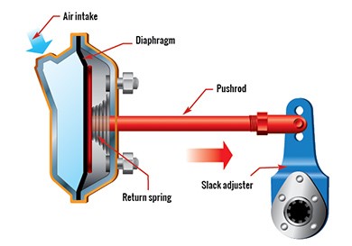
Diagram 3-1: Service brake chamber - Brake applied
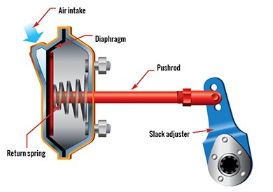
Diagram 3-2: Service brake chamber - Brake not applied
Key points to remember
- The brake pedal is used to apply the service brakes.
- Front wheel-limiting valves reduce the force of the service brakes on the front steering axle.
- Pushrod stroke is produced by compressed air entering the brake chamber.
- Each brake-chamber style, type and size has a specific pushrod stroke-adjustment limit.
- You must not let the pushrod stroke exceed the adjustment limit.