Stormwater management plan and SWMP design
Stormwater management plan and SWMP design (4.0)
4.1 General
The stormwater management plan is the means by which water resource concerns are addressed during development. It will provide the size and location of SWMPs and will demonstrate (through modelling and other techniques) that when integrated, the SWMPs will meet the criteria established to ensure that:
- groundwater and baseflow characteristics are preserved;
- water quality will be protected;
- the watercourse will not undergo undesirable and costly geomorphic change;
- there will not be any increase in flood damage potential; and ultimately,
- that an appropriate diversity of aquatic life and opportunities for human uses will be maintained.
Ideally, planning for stormwater management will have begun early in the environmental planning process (Section 2.3) and will have been integrated with subdivision/site planning (Appendix A). The stormwater management plan and SWMP design can then incorporate opportunities which have been identified and designs which have been developed.
If a subwatershed plan has not been completed, the stormwater management plan will include much of the information that otherwise would be included in the larger scale plan.
The recommended strategy for stormwater management is to provide an integrated treatment train approach to water management that is premised on providing control at the lot level and in conveyance (to the extent feasible) followed by end-of-pipe controls. This combination of controls is the only means of meeting the multiple criteria for water balance, water quality, erosion control and water quantity.
Stormwater management strategies that employ a combination of SWMPs are desirable because they yield the following benefits:
- more effective stormwater management;
- reduction in land area required to implement end-of-pipe solutions;
- enhanced opportunities to integrate SWMPs effectively as amenities;
- decreased total cost when land value is factored in; and
- increased level of public awareness and involvement in the implementation and management of stormwater management initiatives.
To meet water quality objectives, a multi-component approach, in which there is a series of stormwater quality measures, may be used. If in a given situation no single measure is considered sufficient, then two or more controls in series may be expected to provide a higher level of water quality improvement. SWMPs used in a multi-component approach often include oil/grit separators, soakaway pits, sand and bioretention filters, vegetated filter strips, and grassed swales. If special concerns such as recreational activities involving water contact have been identified, additional water quality controls such as ultra violet disinfection units may be required.
Modelling techniques which may be used to develop the system of stormwater management practices are discussed in Section 4.9. The stormwater management plan will also include designs for the major and minor systems that convey the runoff from infrequent and frequent storm events, respectively (Section 4.8).
4.1.1 Lot level and conveyance controls
Lot level and conveyance controls include those that are applied at the individual lot level, those which form part of the conveyance system, and controls which typically serve multiple lots but are only suitable for small drainage areas (< 2 hectares). They can be divided into two categories according to their primary function: storage controls and infiltration controls. Storage controls include:
- rooftop storage – restricting the discharge rate from roof drains to provide rooftop detention of stormwater
- parking lot storage – implementing catchbasin restrictors or orifices in the storm sewer to detain stormwater on parking lots
- superpipe storage – oversizing storm sewers and implementing orifices in the sewer to create pipe storage
- rear yard storage – implementing catchbasin restrictors in rear yard catchbasins to create rear yard storage
All of these measures were designed to detain stormwater to reduce peak runoff rates. In some cases there may be increased opportunity for evapotranspiration. However, detention times are typically short and these measures are not intended to reduce the volume of stormwater runoff. Further, they do not address water balance, erosion, or water quality issues. In addition, there are devices such as oil/grit separators which are suitable as lot level controls but which are also potentially suitable as end-of-pipe controls for small drainage areas with physical constraints. These devices are described in section 4.6.
Infiltration-based controls include:
- reduced grading to allow greater ponding of stormwater and natural infiltration;
- directing roof leaders to rear yard ponding areas, soakaway pits, or to cisterns or rain barrels;
- sump pumping foundation drains to rear yard ponding areas;
- infiltration trenches;
- grassed swales;
- pervious pipe systems;
- vegetated filter strips; and
- stream and valley corridor buffer strips.
The primary function of infiltration controls is to mitigate the impacts that urbanization normally has on the water balance (i.e., increased surface runoff, reduced soil moisture replenishment and groundwater recharge). Concentrated infiltration of stormwater collected from larger areas (e.g., infiltration basins, an end-of-pipe infiltration type control) will not match the characteristics of distributed infiltration which occurred under pre-development conditions. The natural hydrologic cycle can be maintained to the greatest extent possible by lot level infiltration controls.
Infiltration technologies can achieve water quality enhancement; however, stormwater containing high concentrations of suspended solids will tend to clog these controls. Further, infiltration of contaminated water can impair groundwater quality. Therefore, these measures are ideally suited to the infiltration of relatively clear stormwater, such as stormwater from rooftops which contains only atmospheric contaminants (i.e., contaminants deposited on the rooftop by precipitation or dryfall) or foundation drainage.
If the quality of the stormwater is such that there may be a problem with clogging in the system or degradation of groundwater quality, pre-treatment is required. Infiltration controls are not appropriate for applications with the potential for highly contaminated stormwater (e.g., industrial land uses).
By reducing the size of storm sewer infrastructure and end-of-pipe facilities, lot level and conveyance controls provide economic benefits. Section 4.8 provides guidance with respect to the reductions in end-of-pipe storage requirements which various lot level and conveyance controls allow.
The successful implementation of many lot level and conveyance measures require innovative subdivision design. In addition to the measures which are the focus of this manual, there are complementary controls which can be undertaken by home owners. For example, cisterns or rain barrels may be used in combination with bioretention gardens. Lot grading can be used to direct runoff to garden areas. Trickle irrigation systems may be used to make use of captured runoff in soils with lower infiltration capacities. Public education programs within municipalities can help to educate the public on the role they can play in the application of complementary measures.
A significant challenge in designing and implementing a stormwater management strategy which incorporates lot level techniques and other source controls is that many of these initiatives will be implemented on lands held in private ownership. Consequently, maintenance and the long-term effectiveness of the system is contingent on the actions of the landowner. Landowner education is the key to ensuring that systems remain effective over time. The successful application of lot level landscape solutions therefore requires the commitment of the municipality and the establishment of creative partnerships between the developer, municipality and landowner to realize consistent benefits over the long term.
4.1.2 End-of-pipe controls
End-of-pipe stormwater management facilities receive stormwater from a conveyance system (ditches, sewers) and discharge the treated water to the receiving waters. The purpose of end-of-pipe SWMPs is to control the impacts of urbanization which remain after lot level and conveyance controls have been applied. In most cases, new urban developments (unless they are small or of very low density) will require some sort of end-of-pipe SWMP. Some SWMPs that have been applied as end-of-pipe SWM facilities include:
- wet ponds;
- wetlands;
- dry ponds; and
- infiltration basins.
Other SWMPs applied in some cases as end-of-pipe facilities for smaller areas include filters and oil/grit separators.
Designs are possible which form a continuum from wetland to wet pond. The main criteria for differentiating between the types of facilities are the proportions of deep (> 0.5 m) and shallow areas (< 0.5 m). A wet pond has the greatest percentage of its volume provided in deep water zones. Aquatic plants are concentrated on shallow shelves around the perimeter. These shallow zones typically comprise less than 20% of the surface area of the facility. In contrast, wetlands are dominated by shallow zones (typically > 70% of the volume). Hybrid wet pond-wetland systems combine the two types in series with a minimum of 50% of the volume being provided in deep water areas.
Virtually all new wet facilities (i.e., those having a permanent pool) designed in Ontario have an extended detention storage component, in part due to the guidance provided in this document and its predecessor, but largely because of their multi-purpose design (i.e., water quality, quantity and erosion control). Extended detention storage refers to the active storage which is used during and after a runoff event, but which subsequently drains. The extent to which the active storage is filled by an event depends upon the volume of runoff. Section 3.3 provides a more detailed description of the functions of the permanent pool and active storage elements of ponds and wetlands.
Other jurisdictions draw a distinction between "wet ponds" and "extended detention wet ponds." In the former, water is discharged at the same rate as water is received, while in the latter, water is released more slowly.
Concerns are sometimes expressed regarding the ancillary aviary, terrestrial, and aquatic habitat provided by ponds and wetlands. While the design of these stormwater facilities does not specifically seek to create habitat conditions, habitat is usually created (as a natural consequence). Hence, there are often concerns relating to bio-accumulation of stormwater contaminants and the destruction of habitat during maintenance.
The loss of natural wetlands is, in itself, a major issue which has led to a provincial wetland policy. Some view stormwater wetlands as a replacement for lost natural wetlands; however, stormwater facilities will not have the same attributes as natural systems. It must be recognized that stormwater ponds and wetlands are first and foremost stormwater management facilities that must be maintained. They should not be considered as significant natural areas which require environmental protection. Equally important is that the use of natural wetlands for stormwater quality enhancement is not allowed since the introduction of stormwater may alter the hydrologic regime and chemical/biological composition of the wetland.
4.2 Siting of stormwater management facilities
Site conditions must be addressed in the development of a stormwater management plan. Physical factors may suggest the use of particular SWMPs and preclude the use of others, or they may point to special design requirements (e.g., lining a pond). Factors which should be considered in the evaluation of the physical feasibility of SWMPs include:
- topography;
- soil type;
- depth to bedrock;
- depth to seasonally high water table; and
- drainage area.
Table 4.1 summarizes the physical constraints which could limit the use of lot level, conveyance, and end-of-pipe controls, and further detail is provided in the subsequent sections.
End-of-pipe SWMPs should normally be located outside of the floodplain (above the 100 year elevation). If the facility is multi-purpose in nature (e.g., providing quantity control in addition to quality and erosion control) it must be located above the highest design flood level. In some site- specific instances, SWMPs may be allowed in the floodplain if there is sufficient technical or economic justification and if they meet certain requirements:
- The cumulative effects resulting from changes in floodplain storage and balancing cut and fill do not adversely impact existing or future development;
- Effects on corridor requirements and functional valleyland values must be assessed. SWMPs would not be allowed in the floodplain if detrimental impacts could occur to the valleyland values or corridor processes;
- The SWMPs must not affect the fluvial processes in the floodplain; and
- The outlet invert elevation of the SWMP should be higher than the 2 year floodline and the overflow elevation must be above the 25 year floodline.
| SWMP | Topography | Soil | Bedrock | Groundwater | Area |
|---|---|---|---|---|---|
| wet pond | none | none | none | none | > 5 ha |
| dry pond | none | none | none | none | > 5 ha |
| wetland | none | none | none | none | > 5 ha |
| infiltration basin | none | loam (min. inf. rate ≥ 60 mm/h) | > 1 m below bottom | > 1 m below bottom | < 5 ha |
| infiltration trench | none | loam (min. inf. rate ≥ 15 mm/h) | > 1 m below bottom | > 1 m below bottom | < 2 ha |
| reduced lot grading | < 5% | loam (min. inf. rate ≥ 15 mm/h) | none | none | none |
| soakaway pit | none | loam (min. inf. rate ≥ 15 mm/h) | > 1 m below bottom | > 1 m below bottom | < 0.5 ha |
| rear yard ponding | < 2% | loam (min. inf. rate ≥ 15 mm/h) | > 1 m below bottom | > 1 m below bottom | < 0.5 ha |
| grassed swales | < 5% | none | none | none | < 2 ha |
| pervious pipes | none | loam (min. inf. rate ≥ 15 mm/h) | > 1 m below bottom | > 1 m below bottom | none |
| vegetated filter strips | < 10% | none | none | > 0.5 m below bottom | < 2 ha |
| sand filters | none | none | none | > 0.5 m below bottom | < 5 ha |
| oil/grit separators | none | none | none | none | < 2 ha |
In most cases, online facilities (those located within a watercourse) are discouraged because of concerns for wildlife movement, fish passage and disruption of energy inputs. On-line stormwater quantity facilities may be acceptable if designed such that the bank full flow, and hence fish movement, is not impeded/obstructed, and provided the foregoing requirements are met. On-line quality ponds can only be approved if issues of aquatic habitat can be resolved. An on-line facility can only be proposed in the context of a subwatershed plan.
In all development submissions, there should be a concerted effort to preserve the existing watercourse in its natural state. In cases where watercourse alterations are deemed necessary, the alterations should be designed using natural channel design techniques. This will require that the current stream reach be assessed using a stream classification system and that any alterations must account for hydrologic and hydraulic changes as a result of urbanization and the preferred stream function/morphology. Guidance on natural channel design techniques is provided in "Natural Channel Systems: An Approach to Management and Design" (Ministry of Natural Resources, 1994). Alterations to watercourses will, in most cases, require authorization under Section 35 (2) of the federal Fisheries Act.
The location of end-of-pipe stormwater management facilities is a contentious issue since the use of tableland reduces the overall area available for development. In an effort to minimize the loss of developable land, some municipalities allow the use of parkland dedication for SWMPs which offer recreational opportunities such as trails and playing fields. By offsetting the potential loss of land area available for development, the stormwater management facility, designed in whole or in part as usable parkland, may be considered acceptable.
4.3 Design modifications for cold climates
An extensive review of cold climate design considerations was undertaken by the Centre for Watershed Protection (1997). Much of the information contained in the document is based on the results of a survey conducted among practitioners operating in cold climates. The major recommendations relating to cold climate design include:
- Increased storage volumes to account for volume reductions due to ice and effects of multi-day spring melt;
- Sizing and location of inlets and outlets to avoid ice clogging and freeze-up; and
- Prohibition of early spring drawdown for maintenance (avoid discharge of water with low oxygen or high chloride levels).
Many of the study’s recommendations address depth of cover and backfilling practices which are standard in Ontario. However, the recommendations regarding storage volume increases and designs to limit problems due to freezing warrant consideration and are discussed further below.
4.3.1 Volume modifications
A number of factors combine to make water quality treatment of winter runoff more difficult. Typically, a finer range of particles is washed off in winter due to the lower flow rates associated with melt events. Finer particles require longer to settle and so the relative removal efficiency may be expected to drop in winter. In many situations, ice formation will reduce the effective volume of a permanent pool (causing more frequent overflows or reduced event capture). Ice formation may eliminate a permanent pool entirely so that only active storage is available for treatment.
The Centre for Watershed Protection (CWP) design supplement suggests increasing the water quality volume provided in order to accommodate multi-day snowmelt events. This is not necessary for the volumes recommended in Table 3.2 of this manual because they were derived using a continuous modelling approach which accounts for snow accumulation and melt.
CWP also suggests adding compensatory volume to account for the expected maximum ice thickness and setting the minimum active storage volume to 25% of the total volume (active and permanent pool). The latter measure ensures that some treatment will continue to occur when the pool is completely frozen over. In most cases where water quality and erosion control storage are provided in the same facility, the minimum active storage volume for water quality will be met without the need for additional volume.
The former measure may be particularly important in more northern portions of the province where temperature regimes are such that ice cover may persist into the spring when runoff rates and contaminant washoff are more of a concern than they typically are during the winter. In these areas of the province, it is recommended that the permanent pool volume be increased by an amount equal to the expected volume of the ice cover.
The thickness of ice can be estimated using Stefan’s Equation (Ashton, 1986):
Equation 4.1: Stefan’s Equation
h = α(Df)0.5
where:
- h
- ice thinkness in millimeters
- α
- coefficient of ice growth
- Df
- the sum of freezing degree-days
Table 4.2 indicates values for the coefficient of ice growth. Work done at a pond in Kingston, Ontario, indicated that a coefficient value of 15 produced results close to measured values (Marsalek, 1997). The pond operated with a constant subsurface inflow, which tended to limit the build-up of ice. In general, it is expected that most ponds will be small enough and will receive sufficient inflow to behave more like a river (in terms of ice build-up) than a lake. Where possible, however, the designer should consult with the local municipality or conservation authority concerning local knowledge on ice depths.
| Condition | α(mm°C-0.5d-0.5) |
|---|---|
| Theoretical Maximum | 34 |
| Windy lakes with no snow | 27 |
| Average lake with snow | 17-24 |
| Average river with snow | 14-17 |
| Shelter river with rapid flow | 7-14 |
4.3.2 Modifications to inlet and outlet design
A number of the recommendations of the Centre for Watershed Protection (1997) study regarding inlets and outlets should also be considered:
- Slopes of inlet and outlet pipes should be > 1%;
- Minimum diameter of inlet and outlet pipes should be 450 mm;
- Submerged or partially submerged inlets should be avoided where possible; where a submerged inlet is required, its obvert should be located 150 mm below the expected maximum ice depth;
- Where a submerged berm is used to separate the forebay from the remainder of the pond, the crest of the berm should be set to ensure that there is adequate capacity to pass the design flow (accounting for the expected maximum ice depth);
- Submerged outlet configurations (reverse sloped pipe, baffle plate) should be set 150 mm below the expected maximum ice depth; reverse sloped pipes should have a minimum diameter of 150 mm; and
- Where a very small orifice (e.g., 75-100 mm) is required for discharge control, the design should provide for overflow caused by freezing (i.e., provide a secondary high-level orifice of larger diameter or other appropriate design feature.)
Specific recommendations for cold climate design are provided in the subsequent sections describing each SWMP.
4.4 Mitigation measures for increased temperature
There are a number of reports which indicate that urban development end-of-pipe SWM facilities increase the temperature of water before it is discharged to the receiving waters (Beland, 1991, Galli, 1990, Schueler, 1992). Galli (1990) found that there is an increase in water temperature with all types of urban development SWMPs. These reports also stress, however, that an increase in water temperature is inevitable if an area is developed (i.e., urbanization causes stormwater temperature increases). This observation is based on current development practices. It is anticipated that employing the integrated approach to stormwater management described in Section 2.3 and Appendix A, and incorporating some of the techniques presented, will minimize the temperature increase associated with urbanization.
Literature values of temperature increases with different types of end-of-pipe stormwater management facilities have been recorded (Galli, 1990) and are provided in Table 4.3.
| SWMP Type | Temperature Increase |
|---|---|
| Infiltration Basin | 1.4°C |
| Wetland (extended detention) | 3.4°C** |
| Dry Pond (extended detention) | 2.9°C |
| Wet Pond (extended detention) | 5.1°C |
* Guideline based on monitoring – detailed calculations supersede this table.
** Original report value modified since the wetland design permanent pool was undersized resulting in a low ΔT
Wet ponds and wetlands can compound the temperature increase due to urbanization by maintaining water in the facility between storms and allowing it to acclimate to the air temperature. There are several techniques that can be used to reduce thermal impacts.
Pond configuration
The configuration of a pond will affect its temperature. The length-to-width ratio should be maximized to prevent the occurrence of large open areas of water which cannot be shaded by riparian vegetation. Planted berms and islands can be used in ponds that have a poor configuration due to site specific topography/land availability.
Riparian planting strategy
Planting in the shoreline fringe and flood fringe zones of a wet pond help to shade the pond and minimize temperature increases during inter-event periods. The planting strategy should incorporate designs which shade open water areas when the vegetation reaches maturity.
Bottom-draw outlet
There are temperature benefits from a bottom-draw facility, although this is dependent on the size of the permanent pool and the release depth. There is a minimal difference in water temperature within the top metre of a permanent pool. Lower temperatures (in the order of several degrees Celsius) occur several metres below the permanent pool surface. Ponds with permanent pool depths greater than 3 metres, however, are likely to become thermally stratified during the summer months. The water at depth can become anoxic, and there is a potential for metals and nutrients to be remobilized. Although the oxygen deprivation can be solved by re-aeration at the outlet (e.g., discharge over rocks), the discharge of the polluted water would be undesirable. Accordingly, ponds with a very deep release (> 3 m) should consider re-aeration in the pond itself to prevent thermal stratification from occurring. However, this may reduce sedimentation and resuspend sediment collected at the pond bottom.
Subsurface trench outlet
Treatment of water, by routing the discharge through a subsurface trench filled with clear stone, has also been suggested to reduce temperature. As the water flows through the trench, heat is transferred to the stone. It is purely a conveyance system which does not rely on infiltration; however, there is relatively little knowledge with respect to the success of these systems.
The dimensions of the system depend on the intended range of release rates, and the proximity of the pond to the watercourse. The length of the trench should be maximized to increase the opportunity for heat transfer. The cross-sectional area of the trench should be sized based on the design conveyance flow which does not necessarily have to match the design release rate from the pond (especially if the pond will accommodate the runoff from relatively large storms; i.e., > 25 mm). The trench should be designed to accommodate frequent events (i.e., ≤ 10 mm) which will have a greater effect on the thermal regime of the receiving water.
The trench should be wrapped with non-woven filter fabric to prevent the native material from blocking the pore space in the stone/rock. The stone should be relatively small (13 mm - 25 mm) since smaller stones will have a greater total surface area available for heat transfer.
Night time release
Monitoring evidence (Beland, 1990 unpublished) suggests that the water in stormwater ponds cool during the night as a result of ambient temperature fluctuations that can be up to 5°C. Generally, the lowest pond temperatures were recorded during the early morning (5 A.M. - 7 A.M.) indicating that very early morning releases should be targeted for facilities which are designed with real time controls.
Outlet channel design
In cases where there is a lengthy outlet channel from the end-of-pipe SWM facility to the receiving waters, natural channel design techniques can be employed. Guidance on natural channel design techniques is provided in "Natural Channel Systems: An Approach to Channel Management and Design" (Ministry of Natural Resources, 1994). The outlet channel from an end-of-pipe SWM facility to the receiving waters should be shaded by plantings to minimize the temperature of the water discharged to the receiver.
4.5 Lot level and conveyance controls
4.5.1 Rooftop storage
Flat building roofs can be used to store runoff to reduce peak flow rates to storm sewer systems. Rooftop storage is economical and requires little extra cost during construction. It is generally applicable to large flat commercial and industrial rooftops. Residential roofs are usually peaked with few opportunities for storage. Rooftop storage is widely applied for infill development scenarios to mitigate the need for downstream storm sewer size increases. Few regulatory agencies allow rooftop storage to reduce downstream post-development peak flow rates for new sites. Local regulatory agencies should be consulted to determine what is allowable.
Design guidance
Storage volumes and release rates
Plates or weirs are used in rooftop drainage hoppers to control the rate of discharge and depth of storage. Drainage hoppers can discharge to the internal building drainage system or externally to the ground.
Discharge rates for pre-manufactured rooftop drainage hoppers are specified by the manufacturer. Typically, discharge values for each hopper can range from 1 to 15 L/s. Storage is user determined for dead level or slightly sloped roofs. Large commercial roofs can store 50 mm to 80 mm of runoff. The 100 year 24 hour rainfall amount for southern Ontario is approximately 100 mm. Detention times are usually between 12 and 24 hours. Structural/mechanical engineers should supervise the detailed design of rooftop storage to ensure that loadings are not exceeded.
Emergency overflows
Openings must be designed in the roof parapet walls to ensure loading requirements are not exceeded during excessive runoff events or in case roof hoppers are blocked. Openings will limit the depth of ponding and the loading to the building. Rooftop storage requires periodic inspections and prompt maintenance. More frequent inspections for blockages should be made during the winter and fall months.
Hopper location
The location of hoppers is a function of the building roof length, width and slope. The manufacturer commonly supplies guidelines for determining the location of the hoppers. Typically, hoppers are located 10 m to 15 m from the roof parapet and the distance between hoppers is approximately 30 m.
Drain pipe sizing
Vertical drain pipes should be sized to convey the maximum flows discharged from the roof hoppers. Vertical pipe capacities range from 2 L/s for 50 mm diameter pipes to 40 L/s for 150 mm diameter pipes.
Leakage
Improved waterproofing techniques are required during construction to prevent leakage of ponded runoff.
Technical effectiveness
Rooftop storage is highly effective in reducing downstream peak flow rates. However, the volume of stormwater runoff to the sewer system is not reduced.
4.5.2 Parking lot storage
Parking lots can be used to store runoff to reduce peak flow rates in storm sewer systems. Parking lot storage is economical with slightly increased costs for construction. It is generally applicable to commercial and industrial lots. Parking lot storage is not used in residential areas due to the small parking areas. It has been widely applied for infill developments to mitigate the need for downstream storm sewer size increases. Few regulatory agencies allow parking lot storage to reduce downstream post-development peak flow rates for new sites. Local regulatory agencies should be consulted to determine what is allowable.
Design guidance
Storage volumes and release rates
Storage is created when runoff rates are greater than the outflow allowed by the restricted capacity of inlet control devices (ICDs) placed in maintenance holes or catchbasins. Pre-manufactured ICDs can take the form of an orifice plate or plug over the pipe to a catchbasin or maintenance hole. Specialty ICDs can be orifice plates under catchbasin grates.
Generally, ponding depths are limited to 300 mm with durations less than 1 hour. Design criteria can vary significantly between municipalities. Some municipalities require sizing of the control to the pre-development 2 year peak runoff rate for all (2 through 100 year) post-development runoff rates.
Pre-manufactured ICDs have patentable dimensions and discharge rating curves. Simple spreadsheet calculations can be used to size parking lot storage, or computer simulation programs can be used. Calculations may be complicated when building roof storage discharges to surface ponding areas or when storm sewers are used to control ponding levels at catchbasins.
Parking lot grading
Storage at a catchbasin or manhole is limited by the maximum ponding depth and the grade of the parking lot. Generally, grades are greater than 0.5% and less than 5%. Storage capacities are reduced for increasing grades assuming a constant ponding depth.
Emergency overflows
Overland flow paths must be designed to accommodate runoff that exceeds the storage capacity at the catchbasins. Debris blocking at the catchbasin grate can reduce outflow rates and create overflows. Overland flow paths can be sewers, swales or the roadway system.
Control location
ICDs can be located in catchbasins or at maintenance holes located on the property boundary. Controls at the property boundary allow the municipality to check the operation of the control at its convenience. Controls at the property boundary will likely result in constant water levels at all catchbasins within the site. Controls at the catchbasins allow for different ponding levels and maximize storage on steeply graded sites.
Ponding locations
Frequent ponding areas should be located away from buildings within the site. Storage of runoff during an event can be a nuisance to parking lot users.
Technical effectiveness
Parking lot storage is highly effective in reducing downstream peak flow rates; however, the volume of storm runoff to the sewer system is not reduced. Normal parking lot maintenance procedures are suitable for parking lot storage areas.
4.5.3 Superpipe storage
A superpipe, consisting of pre-manufactured pipe requiring on-site assembly, can reduce peak flow rates by providing subsurface storage. There are marginal water quality benefits as some of the coarse sediment may settle. Generally, superpipes are utilized for small development sites which lack sufficient surface space to construct detention facilities. Design and construction standards for superpipes are defined by the local municipality or township.
Superpipes are equipped with small outlet pipes. As inflow rates are much larger than outflow rates, runoff is detained. Generally, detention times are on the order of a few hours. Compared to traditional surface facilities, land requirements for superpipes are small while material costs are high.
Design guidance
Inlets and outlets
Inlets and outlets must be sized for each site. Outflow rates may have been previously defined in master drainage plans or storm sewer analyses. Generally, inlets are the on-site storm sewer system that has been designed to convey frequent runoff events from impermeable surfaces. Outlets are much smaller pipes that may discharge to watercourses or existing storm sewer systems.
Length and diameter
The length and diameter of the superpipe will be a function of the storage required to meet off-site discharge rates. Maximum pre-manufactured diameters are approximately 3 m. However, the maximum pipe size that can be transported to the site due to constraints, such as bridge height, must be considered. Some municipalities have established minimum sizes to facilitate cleaning. Generally, pipes with diameters less than 1.8 m are difficult to clean.
Slope
Minimum slopes are approximately 0.5% as a slope must be maintained to completely drain the pipe. Slopes should be kept to the minimum as steep slopes will reduce the amount of storage available within the pipe.
Emergency overflows
Emergency surface overflow paths should be located and sized to convey the 100 year runoff in case the superpipe (inlet/outlet) becomes plugged or inoperable.
Location
Superpipes should be installed where the pipes can be easily excavated for maintenance. Suitable locations include parking lots and grassed swales adjacent to property boundaries. Superpipes should be located in close proximity to fire hydrants that supply flushing water for the removal of sediments.
Maintenance
Personnel access points should be located at the upstream and downstream ends of the superpipe. For safety precautions, confined space entry procedures will be required for maintenance personnel when flushing or removing sediments. Upstream removal of sediments will extend the maintenance interval (oil/grit separators and/or other pre-treatment devices can be used for this purpose).
Technical effectiveness
Superpipes are very effective in reducing site peak flow rates; however, they do not significantly improve water quality. Special maintenance considerations are required for clearing.
4.5.4 Reduced lot grading
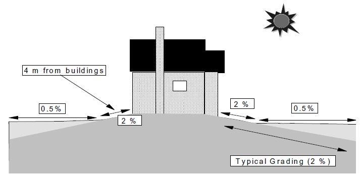
Typical development standards require minimum lot grades of 2% for adequate drainage of stormwater away from a building. Alternative Development Standards (Ministry of Municipal Affairs and Housing, 1995) suggest reducing minimum lot grades from 2% to 0.5%. Despite this, the designer should check the acceptability of this practice with the local municipality.
Design guidance
Soils
Reduced lot grading can be implemented where soils have a percolation rate ≤ 15 mm/h. This generally includes all soils coarser than a loam (Table 4.4). Table 4.4 should be used as a screening tool to determine if site conditions may be suitable for infiltration type controls. However, site testing should be undertaken to confirm actual soil percolation rates. Scarification, or tilling of the soil to a depth of approximately 300 mm, will enhance infiltration; thereby helping to overcome the soil compaction that normally occurs during construction.
| Soil Type | Percolation Rate (mm/h) |
|---|---|
| sand | 210 |
| loamy sand | 60 |
| sandy loam | 25 |
| loam | 15 |
Topography
A reduction in the lot grading should be evaluated if the land is naturally flat. In hilly areas, alterations to the natural topography should be minimized (as indicated in Appendix A).
Setbacks
In order to ensure that foundation drainage problems do not occur, the grading within 2 metres - 4 metres of a building should be maintained at 2% or higher (local municipal standards should be reviewed to ensure that the grading around a building is in compliance). Areas outside of this boundary may be graded at less than 2% to create greater depression storage, and promote natural infiltration (Figure 4.1).
Figure 4.1 Lot Grading Changes
Roof leaders
In areas where reduced lot grading is implemented, roof leaders which discharge to the surface should extend 2 metres away from the building.
End-of-pipe benefits
End-of-pipe extended detention requirements will be reduced by decreasing lot grades. The benefits of reduced grades can be assessed based on an increase in pervious area depression storage in hydrological modelling. It is recommended that the pervious depression storage (or initial abstraction) be increased by 1.5 mm for a change in lot grades from 2% to 0.5% (based on a typical lot of 12 m × 30 m). Section 4.8 provides further guidance with respect to adjusting end- of-pipe SWM facility storage to account for lot level and conveyance controls.
Technical effectiveness
There is little experience with reduced lot grading as a standard practice on a subdivision scale. The largest impact this practice will have is on the homeowner’s utility of his or her land. The water ponded on lots may take 24 to 48 hours to drain which may restrict the active use of the land. This impact will be greatest in spring, but negligible during the summer. It is anticipated that the public will be receptive to this alternative standard if they understand its benefits.
4.5.5 Roof leader to ponding areas
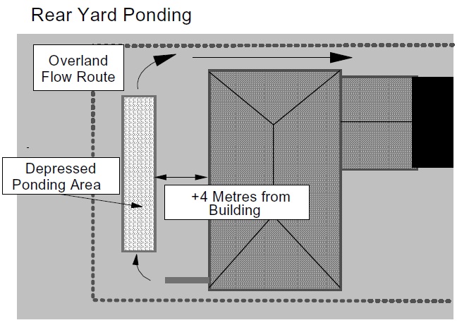
An area for ponding can be created in the rear yard or along the rear lot line. Roof leaders are discharged to the surface and directed to the ponding area. Water is detained in the ponding area until it either evaporates or infiltrates.
A variation on this SWMP adds rainbarrels or cisterns, so that water can be stored for later use in the garden or on the lawn. This is particularly useful in areas with impermeable soils, where infiltration is slow and ponding areas may remain wet for an extended period of time.
Design guidance
Soils
Ponding can be implemented for soils having a percolation rate ;;. 15 mm/h. Infiltration can be improved by tilling the ponding area to a depth of approximately 300 mm before sod is laid.
Storage volume
A minimum storage volume of 5 mm over the rooftop area should be accommodated in the rear yard without overflowing. The maximum target storage volume should be 20 mm over the rooftop area since 90% of all daily rainfall depths are less than this amount.
Ponding depth
The area for ponding should be a shallow depression with a maximum depth of 100 mm. An overland flow path should be established for depths greater than this amount.
Configuration
The configuration of the ponding area will depend on the site-specific layout of the development. The depth of ponding should be minimized as a goal. If possible the length of ponding should be maximized compared to the width to prevent short-circuiting to reduce the potential for groundwater mounding, and to maximize the potential for infiltration.
Location
The area of ponding should be at least 4 metres away from any building foundations to ensure that the ponded water does not increase the amount of foundation drainage (Figure 4.2).
Figure 4.2: Roof Leader Discharge to Rear Yard Areas
In general, surface ponding areas should not be located over sewage system leaching beds to minimize the potential for compaction of the leaching bed and groundwater mounding problems. A hydrogeologist should be consulted with respect to the necessity for mounding calculations and the requirements for a setback from the tile field in areas where surface ponding is proposed.
In general, surface ponding areas should not be located adjacent to highways or major roads.
Common ponding areas
Ponding areas can be created along the rear lot lines by raising rear yard catch-basins such that they are used as an overflow system. Infiltration in the ponding areas can be enhanced by providing an infiltration trench system underneath the swale (see Sections 4.5.6 and 4.5.8).
Roof leader
The roof leader should discharge into the ponding area via a splash pad and overland flow route.
End-of-pipe benefits
An increase in impervious depression storage is the simplest way to assess the benefits of rear yard storage on the end-of-pipe extended detention requirements. If modelling is performed, this would require the rooftop area to be modelled separately from the other areas. The increased depression storage would be equivalent to the depth of storage provided over the entire rooftop area. Further guidance is provided in Section 4.8.
Technical effectiveness
This technique has similar benefits and drawbacks to flatter lot grading. The benefits of this practice outweigh its drawbacks, and therefore, this stormwater lot level control is recommended.
4.5.6 Roof leader discharge to soakaway pits
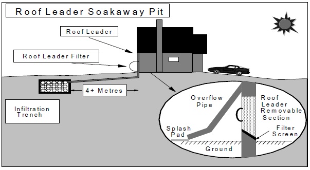
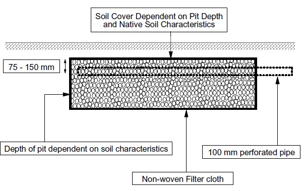
This stormwater lot level control infiltrates roof drainage via an underground infiltration trench (soakaway pit). The roof drainage is conveyed directly to the trench by the roof leader (Figure 4.3). The term soakaway pit is typically used to describe an infiltration trench which serves a single lot and which does not receive road runoff. Since the runoff is relatively clear, pre-treatment is not needed.
Figure 4.3: Roof Leader Discharge to Soakaway Pit
Design guidance
Water table depth
The depth from the bottom of the soakaway pit to the estimated seasonally high water table should be greater than or equal to 1 metre.
Depth to bedrock
The depth from the bottom of the soakaway pit to the bedrock should be greater than or equal to 1 metre.
Soils
Soakaway pits can be used where soils have a percolation rate ;;. 15 mm/h. This generally includes all soils coarser than a loam.
Storage volume
A minimum storage volume of 5 mm over the rooftop area should be accommodated in the soakaway pit without overflowing. The maximum target storage volume should be 20 mm over the rooftop area since 90% of all daily rainfall depths are less than this amount.
Storage configuration
The length and width of a soakaway pit are dependent on the configuration of the development. The length of trench (in the direction of inflow) should be maximized compared to the width to ensure the proper distribution of water into the entire trench and to minimize the potential for groundwater mounding.
The permeability of the native soil will dictate the maximum allowable underground storage depth as indicated by Equation 4.2. Storage depths greater than 1.5 m are generally not recommended for soakaway pits from both a cost, and a compaction perspective. The weight of the water in a deep soakaway pit will compact the surrounding native soil and decrease the infiltration capacity.
There are exceptions, however, to this maximum depth recommendation. In areas with deep sand lenses or significant horizontal soil stratification, deep soakaway pits may be preferred. If, for example, a sand lens is located at a depth of 2 metres, it would be advantageous to construct a deep soakaway pit which drains into the lens. Soils investigations should be undertaken to determine whether these conditions exist.
Equation 4.2: Maximum Allowable Soakaway Pit Depth
d = PT ÷ 1000
where
- d
- maximum allowalbe depth of teh soakaway pit (m)
- P
- percolation rate (Table 4.1) (mm.h)
- T
- drawdown time (24-48 h) (h)
It is recommended that a conservative drawdown time (24 h) be chosen recognizing that the percolation rates into the surrounding soil will decrease over time and that there will likely be a lack of maintenance in some cases.
Soil cover
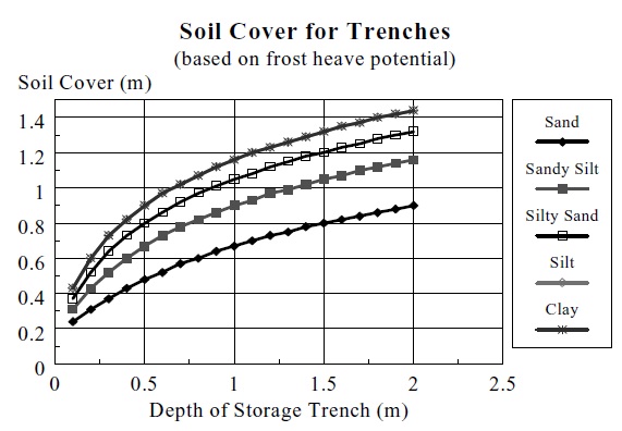
Typically, the pit should be located close to the ground surface; however, this will depend on the depth of storage in the trench, the potential for frost heave, and the stratification of the surrounding soil. The potential for frost heave is dependent on the native soils and the volume of water in the trench which may freeze. Figure 4.4 provides guidance on the recommended minimum soil cover for various subsurface trench depths and native soils. It is based on professional opinion, the expansion of water because of freezing, and the potential availability of water to freeze. Ice lens formation is not anticipated to occur within the trench because of the size of the pores in the storage media.
Figure 4.4: Soil Cover for Trenches
Location
The roof leader is extended underground to an excavated infiltration trench. The trench should be located at least 4 metres away from the foundation of the nearest building to prevent excessive foundation drainage.
Groundwater mounding calculations may be required to ensure that soakaway pits do not interfere with sewage system leaching beds. A hydrogeologist should be consulted with respect to the necessity for mounding calculations and the requirements for a setback from the tile field. It is anticipated that calculations will be required in areas where the soils are marginally acceptable for infiltration.
Common soakaway pits
Common soakaway pits may be viable in areas with compact built forms. The common soakaway pit can be located in neighbourhood park areas or along rear lot lines.
Storage media
The trench is comprised of clear stone (50 mm diameter). Non-woven filter cloth should be used to line the trench to prevent the pore space between the stones from being blocked by the surrounding native material.
Conveyance pipe
The roof leader should extend into the soakaway pit for the full length of the pit. The extension of the roof leader should be perforated to allow water to fill the pit along the length of the pipe. The perforated pipe should be located near the surface of the trench (75 mm - 150 mm from the top of the pit). A typical trench detail is shown in Figure 4.5.
Figure 4.5: Soakaway Pit Details
Overflow by-pass
An overflow pipe should be installed from the roof leader that discharges to a splash pad. A removable filter should be incorporated into the roof leader below the overflow pipe. The filter should have a screened bottom to prevent leaves and debris from entering the soakaway pit. It should be easy to remove so that a homeowner can clear the filter. Frequent use of the overflow pipe will indicate the need for filter screen maintenance.
Technical effectiveness
Soakaway pits for roof leader drainage have been implemented in numerous areas (e.g., Toronto, Maryland). Lindsey et al. (1992) indicated that of 25 soakaway pits monitored, 60% were operating as designed.
Soakaway pits have both benefits and drawbacks compared to rear yard ponding. The benefits include greater recharge (less evapotranspiration) and less inconvenience to the homeowner (less surface water ponding). The drawbacks include greater maintenance and uncertain longevity.
For soakaway pits accepting only roof drainage, the potential for clogging is low as is the risk of groundwater quality degradation. Accordingly, this SWMP is recommended for general implementation.
4.5.7 Sump pumping of foundation drains
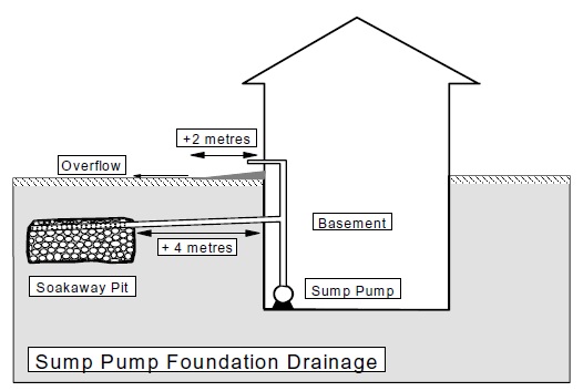
Development standards allow foundation drains to be connected to the storm sewer. Alternative standards (Ministry of Municipal Affairs and Housing, 1995) allow the use of sump pumps to discharge foundation drainage to the surface or soakaway pits (Figure 4.6). Because foundation drainage is relatively clear water, the cost of stormwater management and sewage treatment can be reduced by keeping it separate from storm and sanitary sewers. The municipality should be contacted before recommending this type of control as its use may not be permitted.
Figure 4.6: Foundation Drainage Options
Design guidance
Water table depth
In areas where the seasonally high water table is within 1 metre of the building foundation drains, sump pumps should not be utilized. This requirement is imposed to prevent excessive sump pump operation and to prevent a looped system whereby the sump pump discharges maintain the foundation drainage. Where the use of sump pumps is not feasible, a "third pipe" may be used to convey foundation drainage to the receiving water.
Depth to bedrock
In areas where the depth to bedrock is within 1 m of the foundation drain elevation, foundation drainage by sump pumps is not feasible. This requirement is imposed to prevent excessive sump pump operation and a looped system.
Location
Figure 4.6 demonstrates foundation drainage to a soakaway pit using a sump pump. If a soakaway pit is used, it should be located a minimum of 4 metres away from all building foundations to minimize the contribution of soakaway pit drainage to foundation drainage. If the foundation drains are being discharged directly to the surface, the discharge point at the ground surface should be located at least 2 metres away from all building foundations, and there should be sufficient grade from the foundation wall away from the building (≥ 2%) for 2 metres to 4 metres to convey the foundation drainage away.
Overland flow
Discharges to the surface should be directed to the rear yard to minimize the amount of surface drainage over sidewalks during the winter. Sump pumps discharging to the surface should discharge approximately 0.5 m above the ground surface to prevent blockages in the winter due to ice and snow.
4.5.8 Infiltration trenches
Infiltration trenches in this manual refer to infiltration systems with a subsurface storage component that treat stormwater runoff from several lots as opposed to soakaway pits which are primarily used for a single lot application. Infiltration trenches can be implemented at the ground surface to intercept overland flows, or underground as part of a storm sewer system.
The acceptability of infiltration trenches should be confirmed because of potential concerns for aquifer contamination. In most cases, infiltration trenches will provide marginal flooding and erosion control benefits because they are sized for recharge and water quality.
Design guidance
Drainage area
Infiltration trenches can be implemented for small drainage areas (< 2 ha). The use of trenches for larger drainage areas is inappropriate due to the problems associated with infiltrating a large volume of water in a relatively small area of land. Groundwater mounding problems, compaction, and sealing of the native soil material have a higher potential of occurrence as the volume of water to be infiltrated increases. Further, in terms of the natural hydrological cycle, concentrated infiltration of stormwater collected from large areas will not match the characteristics of pre-development distributed infiltration.
Land use
Infiltration trenches can be implemented for residential land uses. Trenches are best implemented for compact housing (cluster housing, townhouses) in small parks/greenspace areas where several households can drain to a single trench.
Infiltration trenches are not suitable for industrial land uses since there is a high potential for groundwater contamination and/or dry weather spills. Similarly, infiltration trenches are not suitable for commercial parking lots since there is a high potential for dry weather spills and for chloride to enter the trench, and subsequently, the groundwater system.
Water table depth
The seasonally high water table depth should be > 1 m below the bottom of the infiltration trench.
Bedrock depth
The depth to bedrock should be > 1 m below the bottom of the infiltration trench.
Soils
Infiltration trenches are not suitable if the native soil has a percolation rate less than 15 mm/h.
Storage configuration
The depth of the storage layer should be sized to ensure a 24 to 48 hour drawdown (a 24 hour drawdown is recommended) of the stored water based on the percolation rate determined in the field. Equation 4.2 can be used to calculate the maximum allowable storage depth in the trench.
A maximum storage volume equal to the runoff from a 4 hour 15 mm storm should be provided in the trench storage media if the trench accepts runoff from several lots. The length and width of the trench will be determined by the characteristics of the site in question (topography, size and shape).
If a surface trench is designed, the dimensions of the trench will depend on the path of influent water. If stormwater is conveyed to the trench as uniform sheet flow, the length of the trench perpendicular to the flow direction should be maximized. If stormwater is conveyed as channel flow, the length of trench parallel to the direction of flow should be maximized.
In a subsurface trench, the water is conveyed into the trench via a pipe system. In this arrangement, it is recommended that the trench length (parallel to the incoming pipe) be maximized compared to the trench width. This will encourage the uniform distribution of water in the storage layer.
The appropriate bottom area of the trench can be calculated using Equation 4.3. This equation assumes that all of the infiltration occurs through the bottom of the trench.
Equation 4.3: Infiltration Trench Bottom Area
A = 1000V ÷ PnΔt
where:
- A
- bottom area of the trench (m²)
- V
- runoff volume to be infiltrated (Table 3.2)
- P
- percolation rate of surrounding native soil (mm/h)
- n
- porosity of the storage media (0.4 for clear stone)
- Δt
- retention time (24 to 48 hours)
Location/setbacks
Groundwater mounding calculations may be required to ensure that infiltration trenches do not interfere with sewage system leaching beds. A hydrogeologist should be consulted with respect to the necessity for mounding calculations and the requirements for a setback from the tile field. It is anticipated that calculations will be required in areas where the soils are marginally acceptable for infiltration.
The setbacks from wells specified in the Building Code for leaching bed systems shall also be observed for infiltration trenches.
Storage media
The storage media holds the stormwater until it can percolate into the surrounding native material. It is recommended that 50 mm diameter clear stone be used (Figure 4.7). While gravel is the most common medium used, precast infiltration storage media are available which are also generally acceptable.
Figure 4.7: Surface Infiltration Trench
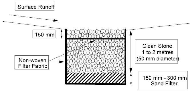
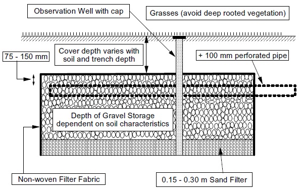
Non-woven filter fabric should be installed at the interface of the trench and the native material to ensure that the latter does not clog the trench. For subsurface trenches, the filter fabric should extend to cover the top of the trench (Figure 4.8). However, this may need to be frequently replaced depending on the volume of suspended solids transported to the trench.
Figure 4.8: Subsurface Infiltration Trench
Filter layer
A filter layer is constructed underneath the storage layer to provide quality enhancement of the stormwater before it infiltrates the native soil. The most common filter medium used in infiltration trenches is sand. The sand layer should be approximately 0.3 m thick (0.15 m - 0.30 m). Grain size is specified based on the effective size (d10 – 10% of the particles are less than this size) and coefficient of uniformity (Cu – the larger the number, the less uniform the material). Sands with an effective size of 0.25 mm and Cu ≤ 3.5, or an effective size of 2.5 mm with a Cu ≤ 1.5, are recommended for filter material.
Peat may be mixed with the sand to enhance the pollutant removal characteristics of the trench. Peat has a high affinity for metals, hydrocarbons, and nutrients (Galli, 1990). Fibric or hemic peat should be utilized to achieve the desired percolation rates. Sapric or well-decomposed peat is discouraged since this type of peat has a slow percolation rate. The percolation rate of filter media should equal or exceed the percolation rate of the native soil material.
Planting strategy
The planting requirements for an infiltration trench are more aesthetic than functional. Grass/herb mixtures are generally acceptable. Plantings with deep roots should be avoided since they can puncture the filter fabric at the top of the trench allowing native soil material to clog the gravel storage layer from above.
Distribution pipes
In an underground trench, water is conveyed into the storage layer by a series of perforated pipes. A header pipe connects to the influent storm sewer and distributes the flow into lateral perforated pipes (≥ 100 mm diameter) which traverse the entire length of the trench. The lateral pipes should be spaced a maximum of 1.2 m apart. The perforated pipes should be located approximately 75 mm - 150 mm from the top of the storage layer.
Overflow/by-pass pipe
A by-pass pipe should be incorporated into the design of an underground infiltration trench to convey high flows around the trench. This will necessitate the construction of a flow splitter upstream of the trench (see Section 4.7). The by-pass pipe may also function as the:
- normal outlet until the site is stabilized (inlet pipe to trench blocked off);
- normal outlet during trench maintenance; and
- normal outlet during winter/spring conditions.
Pre-treatment
In residential areas, where the infiltration trench takes primarily roof and pervious area runoff, the technique can be employed without pre-treatment. If the infiltration trench is being used to treat stormwater runoff from an entire site (including roads and parking lots), pre-treatment is necessary to minimize the potential for suspended sediments to clog the trench.
Sand filters, vegetated filter strips, grassed swales and/or oil/grit separators may be used. Pollution prevention through source controls should also be investigated (sanding/salting practices, public education with respect to street/driveway sediments) in areas where an infiltration trench is proposed.
Construction
Infiltration trenches will only operate as designed if they are constructed properly. There are three main rules that must be followed during the construction of an infiltration trench:
- Trenches should be installed at the end of the development construction;
- Smearing of the native material at the interface with the trench must be avoided and/or corrected by raking/roto-tilling; and
- Compaction of the trench during construction must be minimized.
Winter operation
In general, infiltration facilities are unsuitable for water quality treatment during the winter/ spring period. They are subject to reductions in capacity due to freezing or saturation of the soil. If road runoff is received, there is an increased likelihood of clogging due to high sediment loads and an increased risk of groundwater contamination from road salt.
If infiltration practices are used as an all-season water quality treatment facility, then doubling the design storage volume for surface infiltration devices to account for reduced infiltration rates is recommended. Redundant pre-treatment (more than one pre-treatment device in series) is recommended for all infiltration facilities receiving road runoff. A pre-treatment volume of about 15 mm/impervious hectare is recommended.
Technical effectiveness
Centralized infiltration trenches have a poor historical record of success (Lindsey et al., 1992; Metropolitan Washington Council of Governments, 1992). This lack of success is attributable to many factors:
- poor site selection (industrial/commercial land use, high water table depth, poor soil type);
- poor design (lack of pre-treatment, clogging by native material);
- poor construction techniques (smearing, over-compaction, trench operation during construction period); and
- large drainage area (high sediment loadings, groundwater mounding).
There are many reasons why an infiltration trench can fail. One of the main problems with centralized infiltration trenches is that water from a large area is expected to infiltrate into a relatively small area. This does not reflect the natural hydrologic cycle and generally leads to problems (groundwater mounding, clogging, compaction).
Water quality enhancement can be achieved using infiltration trenches. However, care must be taken to avoid degradation of groundwater quality. Trenches are ineffective quantity control facilities unless substantial storage is provided and the soil conditions are optimum.
4.5.9 Grassed swales
Grassed swales have historically been associated with rural drainage and have been constructed primarily for stormwater conveyance. Stormwater management objectives have changed and grassed swales are now being promoted to filter and detain stormwater runoff. Swale drainage can be a useful technique in areas of low grade, as long as the distance that the flow is to be conveyed is not too long.
The majority of swale systems in Ontario have been designed as "dry" swales. The guidance provided below is for such systems. An alternate design, the "wet" swale, can also be useful in areas where there is sufficient space, especially where soils are not highly permeable, or where there are low lying areas with a high water table.
Wet swales combine elements of dry swale systems and wetland systems. Wet swales are typically wider than dry swales (e.g., 4 m - 6 m) and the check dams are used to create shallow impoundments in which wetland vegetation is planted or allowed to colonize. Because of their width, wet swales are not generally implemented along the front of residential properties, but rather are included where overland flow routes use linear open space areas. Combined systems of dry and wet ponds may be used. Wet swales have been implemented in several highway projects, but monitoring results are limited. A schematic of a wet swale is provided in Figure 4.9.
Figure 4.9: Schematic of a Wet Swale
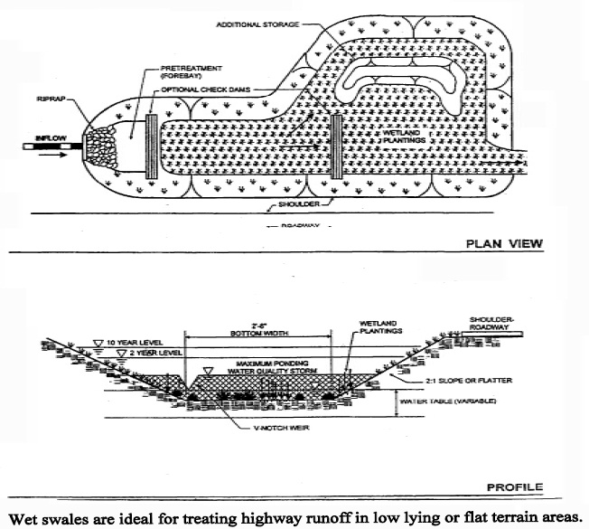
Source: Maryland Stormwater Manual, Volume 1, 1998.
Design guidance
Swale cross-section
Grassed swales can be effective SWMPs for pollutant removal if designed properly. The water quality benefits associated with grassed swales depend on the contact area between the water and the swale and the swale slope. Deep narrow swales are less effective for pollutant removal compared to shallow wide swales. Given typical urban swale dimensions (0.75 m bottom width, 2.5:1 side slopes and 0.5 m depth), the contributing drainage area is generally limited to ≤ 2 ha (to maintain flow ≤ 0.15 m³/s and velocity ≤ 0.5 m/s). Table 4.5 indicates drainage area restrictions for various degrees of imperviousness, based on the assumptions given regarding channel cross-section, slope and cover. The swales evaluated in Table 4.5 are indicative of swales servicing an urban subdivision and not a transportation corridor.
| % Imperviousness | Maximum Drainage Area (ha) |
|---|---|
| 35 | 2.0 |
| 75 | 1.5 |
| 90 | 1.0 |
* Based on the following assumptions: trapezoidal channel, grassed lined (n = 0.035), slope of drainage area = 2%, 2.5:1 side slopes, 0.75 m bottom width, 0.5% channel slope, max. allowable Q = 0.15 m³/s, max. allowable V = 0.5 m/s.
Grassed swales are most effective for stormwater treatment when depth of flow is minimized, bottom width is maximized (≥ 0.75 m) and channel slope is minimized (e.g., ≤ 1%). Grassed swales with a slope up to 4% can be used for water quality purposes, but effectiveness diminishes as velocity increases. Grass should be allowed to grow higher than 75 mm to enhance the filtration of suspended solids.
Flow velocity
As a general guideline, grassed swales designed for water quality enhancement should be designed to convey the peak flow from a 4 hour 25 mm Chicago storm with a velocity ≤ 0.5 m/s. This guideline results in a requirement for wide, flat swales for larger drainage areas.
All grass swales must be evaluated under major system and minor system events to ensure that the swale can convey these storms effectively.
Ditch and culvert servicing
Ditch and culvert servicing is viable for lots which will accommodate swale lengths ≥ the culvert length underneath the driveway (not just the driveway pavement width). The swale length should also be ≥ 5 m for aesthetic and maintenance purposes. This is generally achievable for small lots (9 m) with single driveways or larger lots (15 m) with double driveways.
Winter operation
Swale systems which receive road runoff may have their infiltration capacity diminished over time, as salt effects on soil structure and clogging occur. Swale systems need to be maintained periodically (removal of accumulated sand and addition of mulch to the soil structure) in order to maintain their ability to infiltrate.
Relatively few design modifications are warranted for swales in cold climates, primarily due to their inherent simplicity. The following design modifications will tend to enhance their performance:
- Culverts should have a minimum diameter of 450 mm and a slope of 1% or greater; and
- For swale systems with an underdrain system, the underdrain should have a minimum diameter of 200 mm and should be bedded in gravel.
Performance enhancements
In order to promote infiltration of stormwater and the settling of pollutants, permanent check dams can be constructed at intervals along the swale system. These enhancements are best utilized on large swales where the cumulative flow depth and rate is not conducive to water quality enhancement (V ≥ 0.5 m/s or Q ≥ 0.15 m³/s during the 25 mm 4 hour storm). The distance between check dams can be calculated based on the depth of water at the check dam and the swale channel slope. For example, if a swale has a 1% slope and a check dam height of 0.3 m, the distance between check dams should be 30 metres (or less). Figure 4.10 illustrates an enhanced grassed swale design.
Figure 4.10: Enhanced Grass Swale
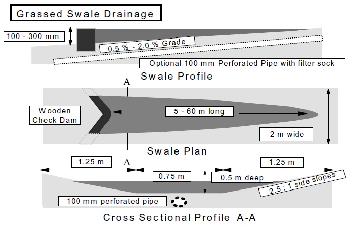
The dam should be constructed out of durable material (wood) which blends into the surrounding landscape. A rock check dam can be used if the swale is located in a remote area which is not subject to vandalism. The dam should be configured in a "V" shape to help minimize scour and erosion of the downstream swale banks ("V" points upstream). The dam should be securely embedded in the swale banks and some rip-rap should be placed downstream of the dam to prevent scour and erosion. The velocity of the design conveyance storm should be kept to approximately 1 m/s whereby smaller stone sizes can be utilized (75 mm diameter).
In areas where the swales are separated by driveway culverts, the culverts can be raised such that the driveway embankment (up to the invert of the driveway culvert) acts as the check dam. This design is more aesthetically appealing and negates the need for rip-rap erosion protection. The driveway culvert should be underdrained, however, to ensure that a permanent pool of water is not created in the swale.
A low flow opening can be created in the check dam to ensure a drawdown time ≤ 24 hours. However, recognizing the potential for clogging of the low flow opening, it is recommended that swales with check dams be underdrained in soils with poor infiltration potential (e.g., clays).
Standard 100 mm perforated pipe (or larger) should be used in combination with a filter sock in any type of underdrain system. Stone storage can be provided around perforated pipes that are installed under swales as a secondary storage medium to promote exfiltration. The appropriate depth of soil cover for the stone storage should be based on the surrounding soil conditions and the potential for frost heave. Figure 4.4 indicates the recommended soil cover based on the native soil type and trench depth.
All grass swales must be evaluated under major system and minor system events neglecting the storage/conveyance below the overflow of any check dam to ensure that the swale can convey these storms effectively.
Technical effectiveness
The effectiveness of swale systems is highly dependent on their design and maintenance. It is therefore recommended that they be used as part of a multi-component approach (i.e., one measure in a series of stormwater quality measures). They may be used for pre-treatment or polishing.
4.5.10 Pervious pipe systems
A few municipalities in Ontario (e.g., City of Nepean, City of Etobicoke) have implemented pervious pipe systems (Figure 4.11). These systems have experienced some problems in the past and are still experimental in nature.
Figure 4.11: Pervious Pipe System
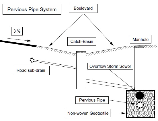
Pervious pipe systems are perforated along their length allowing exfiltration of water through the pipe wall as it is conveyed downstream. The pipe itself is similar to that used for tile drainage on agricultural lands and is available with either a smooth-walled or corrugated interior.
Design guidance
Soils
Pervious pipes can be used where soils have a percolation rate ≥ 15 mm/h.
Water table depth
If a pervious pipe system is implemented in an area where the seasonally high water table is higher than the obvert of the pipe, the pipe will drain the groundwater table. In this scenario, depending on the native soil characteristics and whether the trench or pipe is wrapped in geotextile fabric, soil can be transported into the pipe system undermining the pipe foundation and leading to structural failure. Pervious pipe systems should not be implemented in areas where the seasonal high groundwater level is within 1 metre of the bottom of the storm sewer backfill to ensure this does not happen.
Depth to bedrock
The depth to bedrock should be greater than or equal to 1 metre below the bottom of the perforated pipe storage media to ensure adequate drainage/hydraulic potential.
Storage volume
A minimum storage volume equal to the runoff from a 4 hour 5 mm storm over the contributing drainage area should be accommodated in the pervious pipe bedding/storage medium without overflowing. The maximum target storage volume should be equal to the runoff from a 4 hour 15 mm storm over the contributing drainage area since 80% of all daily rainfall depths are less than this amount.
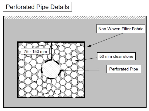
Storage configuration
The exfiltration storage bedding layer should be 75 mm - 150 mm deep above the pervious pipe. A shallow bedding above the pipe is used since the storage above the pipe obvert is not utilized. The depth of bedding below the pipe obvert is dependent on the storm to be exfiltrated and the native soil material. Maximum depths which permit the bedding to drain in 24 hours can be calculated using Equation 4.2. Details of a pervious pipe end section are shown in Figure 4.12.
Figure 4.12: Pervious Pipe Details
The width of storage can be determined based on the rate of exfiltration from the pipe, the proposed length of pervious pipe, and the desired volume of runoff for infiltration. Section 4.8 provides methods for estimating the rate of exfiltration based on the number and size of pipe perforations.
Pipe slope
Pervious pipe systems should be implemented with reasonably flat slopes (0.5%) to promote exfiltration.
Pervious pipe bedding/storage media
Granular A material, or preferably clear stone (50 mm), should be used for the pipe bedding. Granular B is generally discouraged for use as pervious pipe bedding because it contains too many fines which may infiltrate the pipe system.
Pervious pipe systems should be constructed with anti-seepage collars to ensure that exfiltrated water does not travel along the pervious pipe bedding to the outlet. The spacing of anti-seepage collars should be based on the permeability of the native soil material and the pipe slope.
Pervious pipe
Smooth-walled (interior) pervious pipe is recommended for stormwater exfiltration since corrugated pipe has a higher potential for clogging. Furthermore, the maintenance of corrugated pipe via traditional sewer flushing is relatively ineffective since material becomes trapped in the corrugations. A minimum diameter of 200 mm should be used for the pervious pipe to facilitate maintenance.
Geotextiles
Although a filter sock can be used to prevent fines from entering the pipe system from the native material, the sock may prevent fines in stormwater from exfiltrating to the native material. As such, the use of a filter sock may cause clogging at the pipe/sock interface and decrease the longevity of the pervious pipe system.
Non-woven filter fabric installed at the interface between the pipe bedding (exfiltration storage) and the native soil can prevent native material from clogging the voids in the exfiltration storage media.
Pre-treatment
Pervious pipe systems are intended to convey road drainage which has high levels of suspended sediment. Pre-treatment of road drainage is necessary before it reaches the pervious pipe system to enhance the longevity of the system and reduce the potential for groundwater contamination. Pre-treatment of pervious pipe systems can best be achieved by the incorporation of grassed boulevards as pre-treatment areas (Figure 4.11). Stormwater is conveyed from the road to a low boulevard. The boulevard is graded towards catchbasins which are connected to the pervious pipe system. The catchbasins are raised such that water must reach a certain depth in the boulevard before it can overflow into the pervious pipe system. This will provide a sense of an urban cross- section while maintaining the benefits of traditional grass surfaced conveyance systems.
Technical effectiveness
Pervious pipe systems have been implemented in a number of municipalities. In areas where they have been implemented and monitored, numerous systems clogged after several years. The Regional Municipality of Ottawa-Carleton, however, has reported success with pervious pipe systems. Pervious pipe systems can be an effective alternative in retrofit situations (e.g., replacement of existing storm sewers), especially in areas where the catchment has stabilized.
The primary reason for system failure is clogging which can be attributed to several factors:
- Poor Design(storage media, lack of filter cloth, lack of pre-treatment);
- Poor construction practices;
- Inadequate stabilization of development before implementation of pervious pipe(construction timing); and
- Poor site physical conditions (soils, water table.)
One of the problems of implementing pervious pipe systems is construction timing. Ideally, for new development the pervious pipe system would be constructed after the houses have been built and the sod has been laid. However, the road sub-grade needs to be drained and requires the pipe system to be constructed with the road network. The pervious pipe system functions as the storm sewer and therefore must be constructed in its entirety. Although the catchbasins can be blocked to try and prevent sediment laden water from clogging the pervious pipe system, there is a great potential for clogging and compaction of the system during the construction phase of development.
Pre-treatment of road drainage before it reaches the pervious pipe system will enhance the longevity of the system and reduce the potential for groundwater contamination.
Etobicoke exfiltration system
The former City of Etobicoke (now City of Toronto) implemented a double pipe system (regular storm sewer over a perforated pipe) in a retrofit situation on a local road which is not subject to heavy salting or sanding. This system, while relatively expensive if applied in a "new development" situation, provides a means for implementing water quality controls on a retrofit basis in areas of existing development which are undergoing storm sewer rehabilitation or upgrading.
In the Etobicoke system, road runoff is captured in catchbasins and fed into the conventional storm sewer pipe. At the next downstream manhole, flow drops down into a perforated pipe which is plugged at its downstream end. Runoff either exfiltrates, or if the capacity is exceeded, backs up into the conventional storm sewer which conveys it to the next manhole, and eventually to its outlet. The two pipe system provides a contingency conveyance system if the perforated pipe becomes clogged. A double pipe system also allows the perforated pipe to be plugged during the construction phase until the site has stabilized, thereby preventing it from becoming clogged prematurely. The exfiltration system is illustrated in Figure 4.13.
Figure 4.13: Exfiltration System
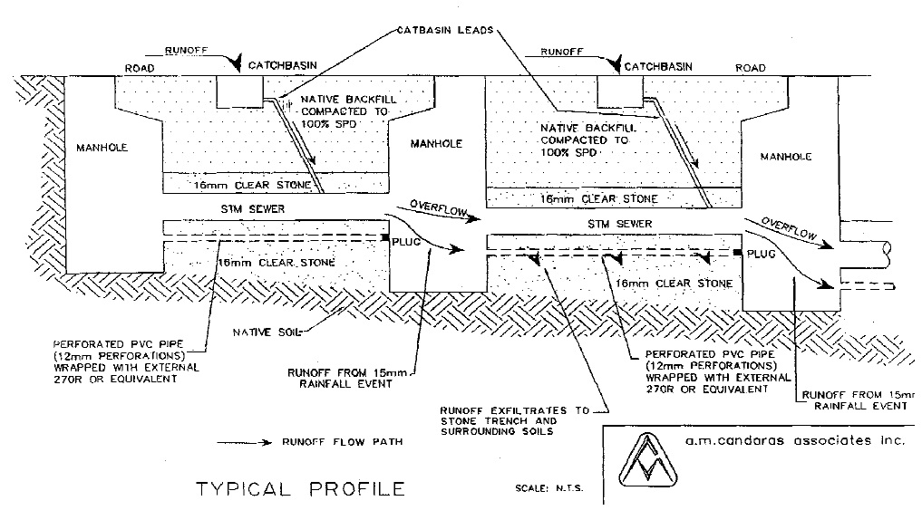
The exfiltration system is best implemented in areas with pervious soils. A variation on the system uses filtration rather than exfiltration and is applicable to areas with tighter soils. In this variation, flow from the catchbasin is discharged to a length of perforated pipe within a gravel- filled trench (in which the conventional storm sewer is also bedded). The runoff filters down through the trench and is collected by a second perforated pipe at the bottom of the trench. The second pipe conveys flow to the next downstream manhole and into the conventional sewer system. If the trench volume or catchbasin capacity is exceeded, a second, higher level outlet in the catchbasin allows flow to be conveyed to the conventional storm sewer. This configuration is illustrated in Figure 4.14.
Figure 4.14: Filtration System
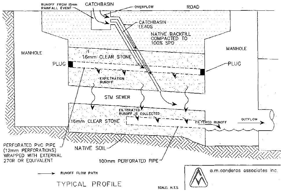
A monitoring program for the Etobicoke systems has been completed (A.M. Candaras Associates Inc., 1997). The study was sponsored by the City of Etobicoke, MOE and the Great Lakes Clean-up Fund (now referred to as the Government of Canada’s Great Lakes Sustainability Fund). Two exfiltration systems (serving areas of about 13 and 30 hectares) and a filtration system (serving 2.4 hectares) were monitored. The systems each work very well and may in fact be overdesigned. The design basis for the systems was the runoff from a 15 mm Atmospheric Environment Service (AES) storm and exfiltration to saturated media. There have been no reported overflows of the perforated pipe system and it has been hypothesized that much higher rates of exfiltration are occurring because the media is not saturated. Since there were no outflows from the system, contaminant discharge was eliminated over the period of monitoring.
4.5.11 Pervious catchbasins
Pervious catchbasins are simply normal catchbasins with a larger sump which are physically connected to an exfiltration storage medium. In some designs, the storage medium is connected to the catchbasin located directly above via a hole or series of holes in the catchbasin floor. Although this design is convenient and conserves land, it is more susceptible to clogging and compaction as a result of the lack of pre-treatment and the weight of the water in the catchbasin. There are manufacturers which offer catchbasin filters for pre-treatment in this type of design. These filters are expensive, however, and need frequent replacement.
A second design (Figure 4.15) uses the catchbasin sump for pre-treatment of runoff and discharges low flows through the wall of the catchbasin to the adjacent exfiltration storage medium.
Figure 4.15: Pervious Catchbasin
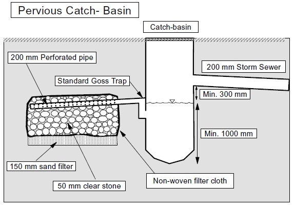
Design guidance
Soils
Pervious catchbasins may be used where soils have a percolation rate ≥ 15 mm/h.
Water table depth
Pervious catchbasins should not be implemented in areas where the seasonal high groundwater level is within 1 metre of the bottom of the infiltration trench.
Depth to bedrock
The depth to bedrock should be greater than or equal to 1 metre below the bottom of the infiltration trench to ensure adequate drainage/hydraulic potential.
Storage volume
A minimum storage volume equal to the runoff from a 4 hour 5 mm storm over the contributing drainage area should be accommodated in the pervious pipe bedding/storage medium without overflowing. The maximum target storage volume should be equal to the runoff from a 4 hour 15 mm storm over the contributing drainage area since 80% of all daily rainfall depths are less than this amount.
Storage configuration
The exfiltration storage depth is dependent on the native soil type/characteristics. Maximum depths can be calculated based on the native soil percolation rate and Equation 4.2. The length and width will depend on the area of land available for the trench (up to the maximum storage volume equal to the runoff from a 15 mm storm over the contributing area).
Storage media
Clear stone (50 mm) should be used as the exfiltration storage medium (porosity = 0.4).
Geotextile
Non-woven filter fabric should be installed at the interface between the exfiltration storage and the native soil to prevent native material from clogging the voids in the exfiltration storage medium.
Pre-treatment
Pervious catchbasins are intended to infiltrate road drainage which has high levels of suspended sediment. Exfiltration of stormwater without pre-treatment will result in poor longevity of the exfiltration system. Large catchbasins with deep sumps will help pre-treat the runoff before it is conveyed to the infiltration trench. However, the amount of pre-treatment will be small even for large manholes, and other pre-treatment measures should be incorporated, if possible, before the stormwater enters the sewer system. Pre-treatment is best achieved by the incorporation of grassed boulevards as discussed in the previous section on pervious pipes.
Technical effectiveness
Pervious catchbasins have been used in both the Cambridge and the Ottawa areas. As with the pervious pipe systems, varying results have been reported. The Regional Municipality of Ottawa- Carleton has reported success with pervious catchbasins. Where difficulties have been observed, it has usually been due to:
- poor design (storage media, filter cloth, lack of pre-treatment);
- poor construction practices;
- inadequate stabilization of development before construction (construction timing); and
- poor site physical conditions (soils, water table).
One of the benefits of pervious catchbasins which are located off-line is that they can be plugged until construction has finished and the development has been stabilized. This helps to prolong the life of the exfiltration storage.
Pre-treatment of road drainage before it reaches the pervious catchbasins will enhance the longevity of the system and reduce the potential for groundwater contamination. Frequent catchbasin cleaning is required to ensure the longevity of this SWMP. Eventually, the exfiltration storage will become clogged and need to be replaced.
4.5.12 Vegetated filter strips
Vegetated filter strips are engineered stormwater conveyance systems which treat small drainage areas. Generally, a vegetated filter strip consists of a level spreader and planted vegetation. The level spreader ensures uniform flow over the vegetation which filters out pollutants, and promotes infiltration of the stormwater.
There are two types of vegetated filter strips: grass filter strips, and forested filter strips. There is a need for further research comparing the efficiency of these two systems for water quality enhancement, since the research to date has focussed on their individual assessment.
Vegetated filter strips are best utilized adjacent to a buffer strip, watercourse or drainage swale since the discharge will be in the form of sheet flow, making it difficult to convey the stormwater downstream in a normal conveyance system (swale or pipe).
Design guidance
Drainage area
Vegetated filter strips are feasible for small drainage areas (< 2 ha).
Slope and width
Vegetated filter strips should be located in flat areas (< 10%) to promote sheet flow and maximize the filtration potential. The ideal slope in a vegetated filter strip is < 5% (1% - 5%).
The vegetated filter strip should be 10 m - 20 m wide in the direction of flow to provide sufficient stormwater quality enhancement (Osborne et al., 1993; Metropolitan Washington Council of Governments, 1992; Minnesota Pollution Control Agency, 1989). The slope of the vegetated filter strip should dictate the actual width. Shorter vegetated filter strip widths (10 m - 15 m) are appropriate for flat slopes, whereas longer vegetated filter strips (15 m - 20 m) are required in areas with a higher slope (5% - 10%).
Level spreader
The level spreader consists of a raised weir constructed perpendicular to the direction of flow. Water is conveyed over the spreader as sheet flow to maximize the contact area with the vegetation. Although the spreader can be engineered using concrete, more natural spreader designs/materials are recommended to maintain a natural appearance.
Figure 4.16 illustrates a typical level spreader design. A small berm is used as the level spreader. It creates a damming effect, preventing stormwater from entering the vegetation until the water level exceeds the height of the spreader. A perforated pipe (100 mm diameter) is installed in the spreader berm to ensure that any water which is trapped behind the berm after a storm can be drained. The perforated pipe should be wrapped in a filter sock to ensure that native material does not infiltrate the pipe.
Figure 4.16: Typical Filter Strip
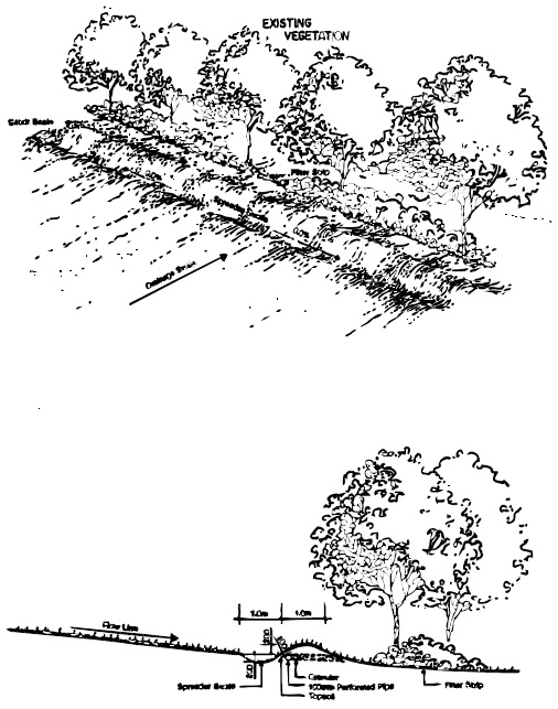
The length of the level spreader should be chosen based on site specifics (topography, outlet location, drainage area configuration). It should be recognized, however, that a shorter level spreader necessitates the trade-off of greater upstream storage to maintain the desired flow depth over the vegetation. It is recommended that the level spreader length, and hence vegetated filter strip length, be as large as possible.
Flow depth
The level spreader and vegetated filter strip should be designed such that the peak flow from a 4 hour Chicago 10 mm storm results in a flow depth of 50 - 100 mm through the vegetation. The flow depth over the level spreader can be calculated using a standard broad crested weir equation (Equation 4.4).
Equation 4.4: Weir Flow
Q = α L H1.5
where:
- Q
- discharge
- α
- coefficient
- L
- length of crest of weir
- H
- head
Storage
Storage will be required behind the level spreader depending on the level of control desired, and the length of the level spreader itself. The amount of storage required should be based on the excess runoff from a 4 hour Chicago distribution of a 10 mm storm, accounting for the flow over the weir. The 10 mm storm was chosen recognizing that 70% of all daily precipitation depths are less than or equal to this amount.
Vegetation
Species such as red fescue, tall fescue and redtop can be introduced in addition to the natural surrounding vegetation to filter out stormwater pollutants. Species native to the area should be used, where commercially available, in the planting strategy.
Technical effectiveness
Vegetated filter strips have limited effectiveness for water quality control due to the difficulty of maintaining sheet flow (i.e., preventing channelization) through the vegetation. They are best implemented as one in a series of SWMPs in a stormwater management plan.
4.5.13 Stream and valley corridor buffer strips
Buffer strips are simply natural areas between development and the receiving waters. There are two broad resource management objectives associated with buffer strips:
- The protection of the stream and valley corridor system to ensure their continued ecological form and functions; and
- The protection of vegetated riparian buffer areas within the valley system to minimize the impact of development on the stream itself (filter pollutants, provide shade and bank stability, reduce the velocity of overland flow).
Although both types of buffers provide only limited benefits in terms of stormwater management, they are an integral part of overall environmental management for sustainable development. The protection of stream and valley corridors provides significant benefits in terms of sustaining wildlife migration corridors, terrestrial and aquatic species food sources, terrestrial habitat, and linkages between natural areas.
Given the larger scale natural system benefits provided by stream and valley corridors, the required width of this type of buffer is best defined at the subwatershed plan level. Individual conservation authorities and municipalities have developed their own guidelines for buffer areas. The designer should confirm local requirements with the applicable authority.
4.5.14 Roof top gardens
Roof top gardens are regarded as a relatively recent innovation in the field of stormwater management, including quality improvement. Roof top gardens may be as simple as a sodded roof which retains water in the soil medium and provides filtration, to something as elaborate as a fully landscaped area with trees, shrubs, gardens, fountains, seating areas and other outdoor amenities. The range of plants suitable for use in roof top landscapes is limited by the extremes of microclimate including high wind, low winter temperature (i.e., no moderating effect from heat stored in the ground) and drought. As a result, alpine or sub-alpine species are well suited to roof top applications. In more elaborate schemes, infrastructure such as irrigation systems, increased insulation and venting from interior heat sources can be employed to overcome the constraints of microclimatic conditions. Roof top gardens have been used extensively and successfully in Europe and their performance is well documented. On this basis, the roof top garden should be considered as a viable stormwater management option which may be used to reduce the scale of associated end-of-pipe treatment facilities within the context of an overall development.
4.6 End-of-pipe stormwater management facilities
4.6.1 SWMP vegetation
Vegetation is an integral part of many SWMPs. Much of the guidance applies to several of the end-of-pipe practices which are described in subsequent sections. The considerations and approaches common to various SWMPs are provided in this section. Where appropriate, details specific to individual SWMP types are provided with other design guidance.
4.6.1.1 Effective use of vegetation
Vegetation should be considered as an important functional component in the design of SWMPs including ponds, wetlands, vegetated filter strips and bioretention filters. Vegetation filters stormwater and takes up nutrients, and in wet facilities, it promotes settling by reducing flow velocities and preventing re-suspension. In addition to enhancing water quality, vegetation effectively achieves the following:
The stabilization of banks, shoreline and slopes
The rooting systems of many species of trees, shrubs and herbaceous plants effectively bind soils to establish a layer that is resistant to erosion. Planting schemes that combine plant species selected for their unique and complementary rooting characteristics are typically most effective in providing long-term stability.
Mitigation of effects on temperature and dissolved oxygen
The strategic location of deciduous and coniferous trees along the edges of a pond, channel or wetland can assist in mitigating undesirable increases in water temperature. In addition, vegetation can contribute to the maintenance of dissolved oxygen levels by inhibiting the growth of algae.
Deterrence of geese
The establishment of dense woody vegetation around the perimeter of a pond or wetland is the most effective means of deterring undesirable species of waterfowl from colonizing and contaminating facilities which have a permanent pool. Minimizing the amount of manicured/ mown land will limit the preferred habitat for geese.
Provision of barriers to mitigate public access
Thickets of thorn bearing shrubs and trees, and twining vines can be combined to create an impenetrable barrier to deter the public from accessing pond areas, steep slopes and other areas which are deemed potentially hazardous.
Enhancement of linkages
The establishment of diverse communities of plants in conjunction with a SWMP can contribute to the establishment of linkages between natural wooded areas, providing terrestrial habitat benefits at a larger scale.
Provision of aesthetic benefits
Vegetation can be utilized to create visual buffers, enhance views and contribute to the establishment of a unique character for a development. Vegetation is one of the most effective tools to blend a SWMP into its surroundings from a visual perspective.
Additional benefits
Vegetation can also be utilized in the design of SWMPs to achieve the following:
- Intercept rainfall;
- Filter out coarse sediments;
- Trap and accumulate floatables;
- Reinforce and maintain the integrity of spreaders, weirs and retaining walls;
- Intercept airborne pollutants;
- Impede colonization by undesirable invasive species; and
- Conceal fencing and structures.
Careful selection of plant material is the critical factor to ensure that functional objectives are achieved. The determination of plant species best suited to a specific application should be made based upon the following considerations:
- Regional climatic characteristics/Hardiness Zone;
- Microclimate conditions;
- Frequency and duration of flooding;
- Soil conditions;
- Environmental features;
- Plant community composition;
- Proximity to roads and other potential sources of airborne pollutants and salt spray;
- Maintenance requirements; and
- Availability of nursery stock/opportunities for transplantation.
The following principles should be applied to guide the selection of plant material and the generation of planting strategies for SWMPs.
Plan for succession
Vegetation communities are dynamic, evolving over time to adapt to the changing environment. Planting design must recognise this evolutionary process to ensure that objectives are achieved over the long term.
Limited monitoring results show that species may shift from those planted to those which are more locally successful, particularly within pools and frequently inundated areas. Planting strategies are important in ensuring effective SWMP operation; however, they do not need to be overly complex since natural succession plays an important role in the ultimate make-up of the vegetation community.
Design to enhance ecological function
Although it may not be an objective to create terrestrial and aquatic habitat in the design of a SWMP, through objective planting design, numerous other ecological objectives can be achieved, including the establishment of linkages, increase in canopy cover, provision of food and shelter and modification of microclimate which will enhance the integrity of the ecosystem at a regional scale.
Have regard for context
An understanding of the ecological, physical and social context of a site will help to direct the selection of appropriate plant species and the assembly and configuration of plant communities which are appropriate to the site and provide the maximum benefit.
Utilize species which are indigenous to the bioregion
Since SWMPs are linked to a network of habitats which are connected by the watercourse downstream of the facility, it is important that plant material within the SWMP site be not only native but indigenous to the bioregion. The introduction of non-native, invasive species can threaten plant communities throughout the watershed and must be avoided.
Maximize diversity
The use of a wide range of native, indigenous trees, shrubs, wildflowers, grasses, sedges and aquatic plants will not only enhance biodiversity on a watershed-wide scale, but also contribute to the system’s resiliency and ability to maintain itself. Plants such as cattail and common reed are aggressive and may thwart diversity goals.
Recognize human factors
Planting design should be developed with a recognition of the requirements of the adjacent residents, users of the site and the community-at-large related to recreational requirements, interpretive opportunities, aesthetics, public safety issues and other associated factors.
4.6.1.2 Developing a planting strategy
Appendix E provides a catalogue of species of trees, shrubs, vines and herbaceous materials which are appropriate for use in the design of ponds, wetlands and other SWMPs. Depth and frequency of inundation, particularly during the growing season, are the primary factors controlling species survival. Water quality may be a secondary consideration. The planting strategy may include up to five zones based on frequency of inundation:
- deep water areas;
- shallow water areas;
- extended detention or shoreline fringe areas;
- flood fringe areas; and
- upland areas.
Some species readily cross category boundaries and many species can survive in the near reaches of neighbouring zones. Category boundaries will differ regionally. Different genotypes of a species may have different ranges of tolerance depending upon genetic and physiological adaptations. The lists in Appendix E may be used as a guide but species selection should also be based on observations of natural systems in the area and sources of plant material. Also keep in mind that new plantings will be less tolerant of extremes than mature individuals.
In natural systems, grasses tend to occur in areas with shallow or limited seasonal flooding. As frequency of inundation and water depth increase, grasses give way to sedges, rushes and spikerushes. These in turn are replaced by broad-leaved emergents such as pickerel weed and arrowhead. Cattails may be found with these plants but also may extend into deeper water where large bulrushes occur. In deep water, submergents will grow provided water clarity is suitable. In the deepest regions, or where water is coloured or turbid, rooted floating plants such as water lilies may be found. Only a few shrubs and trees, such as green ash, buttonbush, black willow, and red osier dogwood, can withstand prolonged inundation.
Deep water areas
Aquatic species, including submergents and floating-leaved species, are appropriate for deep water areas (> 0.5 m). Rooted aquatic plants with floating leaves (e.g., pondweeds) and free floating plants (e.g., duckweed) will grow in the deepest areas. Some emergent species (e.g., cattail and bulrush) may tolerate water depths greater than 0.5 m and could be planted in the shallowest area of the deep water zone.
Shallow water areas
Submergent and emergent vegetation may be used in the shallow water (< 0.5 m) zone. Most emergents should be planted at a water depth < 0.3 m. Minimum side slopes are preferable to maximize the area available for plantings.
Shoreline fringe areas
Shoreline fringe areas are subject to frequent wetting as a result of storm events. This zone can be delineated as the land between the permanent pool, or the pond bottom in dry ponds, and the high water mark for the erosion/water quality control storage. This zone will be subject to higher soil moisture conditions as a result of water level fluctuations during relatively frequent storm events, and the influence of the permanent pool itself in wet facilities during dry weather conditions.
Many wetland sedges, rushes, wildflowers, ferns and shrubs may be planted in the shoreline fringe areas of wet ponds and wetlands. The growing conditions in dry ponds are harsher since there is no influence from a permanent pool. A grass seed mixture can be sown in the fall, although spring is preferable. The shrubs should be planted such that only their lower branches will be inundated during the design storm. At least two shrub species should be planted to improve survival success.
Flood fringe areas
If the wet pond is used to control peak flow rates during infrequent storm events (2 year to 100 year), a zone of infrequent inundation will be created. The influence of a permanent pool and frequent storm events are less pronounced for this area. The planting strategy in this zone may include a variety of grass, herb, shrub, and tree species. A commercially available grass and herb seed mixture suitable for slope stabilization is recommended. The grass and herb seed mixture should be sown in the fall or preferably the spring. At least three species of shrubs and three species of trees should be planted in this zone. There should be a gradual change in planting near the upland zone for aesthetic reasons.
In many designs, as a safety feature and alternative to fencing, thorny vegetation (such as hawthorn or raspberry) is planted in the flood fringe zone. These plants, together with the shallow water and shoreline fringe plantings, act as a barrier to casual entry. Care should be taken, however, that fast growing vines and brambles do not smother young trees.
Upland areas
Upland areas represent the landscaped areas provided as aesthetic amenities around the pond. Upland planting should also be designed to restrict access to steep areas or inlet/outlet locations. At least 5 species should be planted in a random pattern to prevent the establishment of monoculture areas. A large number of young plant stocks, tree whips and seedlings should be planted rather than a small number of large shrubs and trees. Some mature plants should be used, however, to meet immediate wind screening, shading, aesthetic and safety objectives. The upland planting should provide a minimum of a 3 m buffer strip from the maximum design water level mark. The massing of trees and shrubs should be augmented by designated regeneration areas to achieve long-term growth. A naturalized landscape approach should be used which strives for a vegetation community with long-term sustainability and no maintenance requirements.
4.6.1.3 Planting techniques
Loam soils normally have adequate nutrients, provide good water and gas circulation, and have an intermediate texture that supports new plants but allows root or rhizome penetration. Within the permanent pool, 0.3 m of topsoil should be provided to a water depth of 1 m. In the active storage and upland areas, 0.45 m - 1 m of topsoil is needed. It should be stabilized by seeding and engineered methods such as erosion control mats may also be required.
The choice of planting technique is strongly influenced by the plant species selected. It is possible to create suitable conditions for natural invasion and establishment if there is a nearby seed source or the substrate contains a seed bank. It may take a number of years to establish vegetation using this method and the ability to control the type and distribution of plants will be limited.
Grasses are more easily established by seeding than other plant types. Seed germination rates may be quite low for some species, such as some emergent plants that reproduce and spread largely by vegetative means. Various conditions are required for germination of different species. Success may depend upon the ability to establish optimal conditions for seed germination by managing water levels. Optimal conditions for many species will involve shallow flooding and subsequent dewatering or maintaining water levels just below surface. As plants grow, shallow flooding may be desirable to inhibit the growth of competing terrestrial species, but deep flooding may also stress wetland species and overtopping individual plants may result in mortality.
Above the permanent pool, ground cover may be established by hydroseeding or using a custom seed mix in a soil nutrient medium. Protection of the substrate and seed using a biodegradable blanket is recommended particularly in the zone of dynamic water level fluctuation.
Tubers or rhizomes may be planted after dormancy in the fall or in the early spring before the growing season starts. Tubers are forced into soft substrates deep enough to prevent them from floating out and rhizomes are inserted into slits or trenches angled slightly upward.
Whole plants have the advantage of an established root structure for early stability. Shoots at least 10 cm tall reduce mortality due to overtopping but should not exceed 25 cm to reduce the threat of windthrow before the roots have an opportunity to anchor the plant in the substrate. They should be planted in the spring. Bare root seedlings are more susceptible to transplanting shock than containerized plants that have their roots in a suitable growth medium. Refer to the Native Plant Resource Guide for Ontario (Society for Ecological Restoration, 2001) for suppliers of various plants and stock types (seed, seedlings, containers).
Plant spacings of 0.75 m to 1.5 m are commonly used. Decreasing the spacing reduces the time required to achieve complete coverage. The spacing between trees will be larger (5 m - 6 m). In shallow water zones, the planting rows should be perpendicular to the direction of the water flow to minimize the potential for channelization.
Ideally, vegetation should be allowed to overcome planting shock before being subjected to the stresses of flooding and contaminant loadings. Herbaceous species may take up to several years to become well established and woody species may take much longer. During the start-up period, the vegetation should be monitored frequently. If areas of vegetation appear to be unhealthy or dead, replanting may be required.
4.6.2 Wet ponds
Wet ponds are the most common end-of-pipe stormwater management facility employed in Ontario. They are less land-intensive than wetland systems and are normally reliable in operation, especially during adverse conditions (e.g., winter/spring) This reliability can be attributed to several factors:
- performance does not depend on soil characteristics;
- the permanent pool minimizes re-suspension;
- the permanent pool minimizes blockage of the outlet;
- biological removal of pollutants occurs; and
- the permanent pool provides extended settling.
Wet ponds can be designed to efficiently provide for water quality, erosion and quantity control, reducing the need for multiple end-of-pipe facilities. Wet ponds can be designed with extensive landscaping and associated recreational amenities, contributing to the character of the community and enhancing its marketability.
Design guidance
A good design for a wet pond involves attention to a variety of criteria. In current practice the emphasis tends to be on volumetric aspects of design. However, the operational success of a wet pond is often dependent upon other design elements.
Figure 4.17 illustrates a wet pond. A summary of the design guidance given for wet ponds is provided in Table 4.6, and a more detailed discussion of design elements is provided in the following sections.
Figure 4.17: Extended Detention Wet Pond
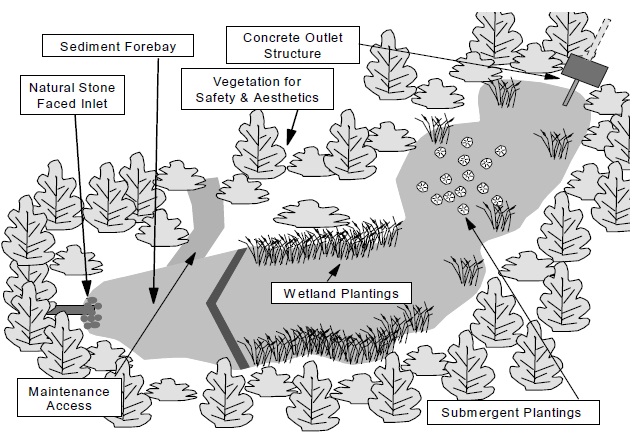
Drainage area
Wet ponds require a minimum drainage area of about 5 hectares to sustain the permanent pool, unless there is another source of water, such as a high local groundwater table. The preferred drainage area for wet ponds is ≥ 10 hectares.
Volumetric sizing
A subwatershed plan will provide guidance with respect to the permanent pool and active storage (extended detention) required. If a subwatershed plan has not been completed, please refer to Chapter 3. The larger of the erosion control active storage and the water quality active storage should be provided. Normally, it is not necessary to provide both types of storage. Where erosion control active storage exceeds 40 m³/ha, the water quality active storage can be neglected (because of similar drawdown characteristics).
| Design Element | Design Objective | Minimum Criteria | Preferred Criteria |
|---|---|---|---|
| Drainage Area | Volumetric turnover | 5 hectares | ≥ 10 hectares |
| Treatment Volume | Provision of appropriate Level of protection (see Section 3.3.1.1) | As per Table 3.2 |
|
| Active Storage Detention | Suspended Solids Settling | 24 hrs (12 hrs if in conflict with minimum orifice size) | 24 hrs |
| Forebay | Pre-treatment |
|
|
| Length-to- Width Ratio | Maximize flow path and minimize short-circuiting potential |
|
From 4:1 to 5:1 |
| Permanent Pool Depth | Minimize re-suspension, avoid anoxic conditions |
|
|
| Active Storage Depth | Storage/Flow Control |
|
|
| Side slopes |
|
|
|
| Inlet | Avoid clogging/freezing |
|
|
| Outlet | Avoid clogging/freezing |
|
Minimum 100 mm orifice |
| Maintenance Access | Access for backhoes or dredging equipment | Provided to approval of Municipality | Provision of maintenance drawdown pipe |
| Sediment Drying Area | Sediment removal | While preferable, should only be incorporated into the design when it imposes no additional land requirement |
|
| Buffer | Safety |
|
Sediment forebay
A sediment forebay (Figure 4.18) facilitates maintenance and improves pollutant removal by trapping larger particles near the inlet of the pond. The forebay should be one of the deeper areas of the pond (at least 1 m) to minimize the potential for re-suspension and to prevent the conveyance of re-suspended material to the pond outlet.
The forebay sizing depends on the inlet configuration, and several calculations can be made to ensure that it is adequately sized.
Figure 4.18: Wet Pond Forebay
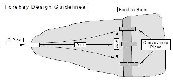
1) Settling Calculations:
The primary method to calculate the forebay volume and length should be based on settling calculations that determine the distance to settle out a certain size of sediment. The methodology assumes that the flow out of the pond dictates the velocity through the forebay and the rest of the pond. Although this is not strictly correct, it is reasonable for the determination of an appropriate forebay length. Equation 4.5 defines the appropriate forebay length for a given settling velocity and hence, the particle size to be trapped in the forebay.
Equation 4.5 Forebay Settling length
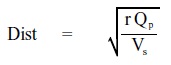
where:
- Dist
- Forebay length(m)
- r
- length-to-width ratio of forebay
- Qp
- peak flow rate from the pond during design quality storm
- Vs
- settling velocity (dependent on desired particle size to settle). It is recommended that a value of 0.0003 m/s be used in most cases.
In all instances the forebay should not exceed one-third of the pond surface area.
2) Dispersion Length:
The dispersion length refers to the length of fluid required to slow a jet discharge (i.e., pipe flow). A check can be made on the forebay length given by the settling calculation (Equation 4.5) to ensure that there is adequate dispersion. Equation 4.6 provides a simple guideline for the length of dispersion required to dissipate flows from the inlet pipe. It is recommended that the forebay length is such that a fluid jet will disperse to a velocity of ≤ 0.5 m/s at the forebay berm.
The dispersion length is usually smaller than the settling length unless there is a large upstream urban drainage area (e.g., 100 ha) or the pond is subject to large inflows (i.e., a combined quantity and quality facility). In cases where a combined facility is designed, the dispersion length should be calculated for the pipe design capacity unless the pipe is designed for storms larger than a 10 year return period. In cases where the pipe conveys flows in excess of a 10 year storm, the dispersion length should be calculated for 10 year flows. In all cases, the forebay length should be greater than or equal to the larger of the lengths given by Equation 4.5 and Equation 4.6.
Equation 4.6: Dispersion Length
Dist = (8Q) ÷ (dVf)
where:
- Dist
- Length of dispersion(m)
- Q
- Inlet flowrate(m³/s)
- d
- depth of the permanent pool in the forebay (m)
- Vf
- desired velocity in the forebay(m/s)
The depth of the permanent pool in the forebay in Equation 4.6 reflects the deep section (> 1 m) of the forebay required to minimize re-suspension and scour. A guideline for the minimum bottom width of this deep zone is given by Equation 4.7:
Equation 4.7: Minimum Forebay Deep Zone Bottom Width
Width = Dist ÷ 8
Generally, the total width of the forebay should provide a length-to-width ratio ;;. 2:1 if a single inlet is proposed for the pond to maximize effective storage (i.e., minimize dead zones).
Although Equation 4.6 provides the length of forebay that ensures a certain velocity in the discharge jet at the end of the forebay, a check should be made using the entire forebay cross-sectional area to ensure that the average velocity in the forebay is less than, or equal to, 0.15 m/s which is empirically recognized as the maximum permissible velocity before which erosion will occur in a channel.
The design flow rate in Equation 4.6 is the peak flowrate of the water quality storm. If this value is not known (e.g., the subwatershed plan specifies the pond sizing based on continuous simulation) it can be approximated using either standard design event modelling practices with a 4 hour Chicago distribution of a 25 mm storm, or using the Rational Method (Equation 4.8) with an intensity given by Equation 4.9.
Equation 4.8: Rational Method
Q = (C×i×A) ÷ 360
where:
- Q
- peak flow rate(m³/s)
- C
- runoff coefficient
- i
- rainfall intensity(mm/h)
- A
- drainage area (ha)
Equation 4.9: 25 mm Storm Intensity
i = 43C + 5.9
where
- i
- rainfall intensity(mm/h)
- C
- runoff coefficient
3) Clearout Frequency:
A check on the permanent pool volume contained in the forebay can be made by estimating the accumulation of sediments in the forebay. A conservative estimate would be to assume the maximum facility removal efficiency in the forebay and to ensure that the forebay volume is equal to, or greater than, 10 years of sediment accumulation. Values of sediment loading/ accumulation per hectare of contributing drainage area are provided in Section 6.4 (Table 6.3) based on the upstream catchment imperviousness.
Forebay berm
The forebay should be separated from the rest of the pond by an earthen berm. The berm can be submerged slightly below the permanent pool or it can extend into the extended detention portion of the pond. Pipes can be installed in the berm as either the primary conveyance system from the forebay to the pond, or as a secondary conveyance system to supplement flows over a submerged berm. In either case, flow calculations should be made to ensure that the berm does not provide a flow restriction which would cause the entire forebay (not just the berm) to overflow under design conditions. The calculations should account for the potential ice thickness over the berm.
The inverts of any conveyance pipes installed in the berm should be set at least 0.6 m above the bottom of the forebay. This will prevent the siphoning of settled material from the bottom of the forebay into the rest of the pond. A maintenance pipe should also be installed in the berm to draw down the forebay for maintenance purposes. If only the forebay is drawn down during maintenance (i.e., maintenance pipe connects to the outlet directly and/or the forebay will be pumped out) the forebay berm must be designed as a small dam since the rest of the pond will not be drained.
If a submerged berm is used, the berm height should be 0.15 metres - 0.30 metres below the permanent pool elevation. A submerged berm provides additional safety benefits (the public is not tempted to walk on the berm) and may be planted with emergent vegetation to promote filtration of water as it passes over the berm.
Detention time
A detention time of 24 hours should be targeted in all instances, unless the outlet is susceptible to clogging due to its small size (i.e., drainage areas < 8 ha). If the outlet may be prone to clogging, the detention time can be reduced to a minimum of 12 hours. The detention time is approximated by the drawdown time.
The drawdown time in the pond can be estimated using Equation 4.10. Equation 4.10 is the classic falling head orifice equation which assumes a constant pond surface area. This assumption is generally not valid, and a more accurate estimation can be made if Equation 4.10 is solved as a differential equation. This is easily done if the relationship between pond surface area and pond depth is approximated using a linear regression.
Equation 4.10: Drawdown Time
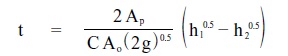
or if a relationship between Ap and h is known (i.e., A = C2h + C3)
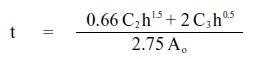
where:
- t
- drawdown time in seconds
- Ap
- surface area of the pond(m²)
- C
- discharge coefficient (typically 0.63)
- A0
- cross-sectional area of the orifice(m²)
- g
- gravitational acceleration constant (9.81,/s2)
- h1
- starting water elevation above the orifice (m)
- h2
- ending water elevation above the orifice (m)
- C2
- slope coefficient from the area-depth linear regression
- C3
- intercept from the area-depth linear regression
Minimum orifice size
The smallest diameter orifice accepted by most municipalities to ensure that clogging does not occur in a stormwater system is 75 mm. The preferred minimum orifice size is 100 mm where the effects of freezing are a concern. It is recommended that this latter size be maintained for exposed outlet designs (i.e., reverse sloped pipes). In instances where a perforated riser outlet is designed, the orifice is protected by the smaller perforations in the riser and a minimum orifice size of 50 mm is acceptable. Where small orifices are required, consideration should be given to providing an overflow outlet which would operate in the event that blockage of the primary orifice occurs.
Length:width ratio
The flow path through a pond directly influences the overall performance. One of the most common problems associated with first generation pond designs was the construction of the outlet close to the inlet. Another common problem involved having multiple stormwater inlets at opposite ends of the pond based on stormwater servicing convenience. In each case, the effective volume of the facility can be reduced.
Wherever possible, all stormwater servicing should be conveyed to one inlet location at the pond. In order to provide the longest flow path through the pond, the inlet to the pond should be located as far away as possible from the pond outlet. Recognizing that a specific storage volume is required to be provided in the pond, the minimum flow path in a pond is generally described by the length-to-width ratio. A pond with a length-to-width ratio ≥ 3:1 will have an acceptable flow path. Preferred length-to-width ratios range from 4:1 to 5:1.
Berms in the pond to re-direct flows at certain elevations and lengthen the effective flow path are an acceptable design feature. They may improve pond performance by ensuring that short- circuiting cannot occur. If the berms are vegetated, the vegetation will help to filter the stormwater, further enhancing the performance. In some areas of the province, this is called a "serpentine" design (Figure 4.19). The addition of berms, however, will increase the land consumption of ponds.
Figure 4.19: Low Flow Berming
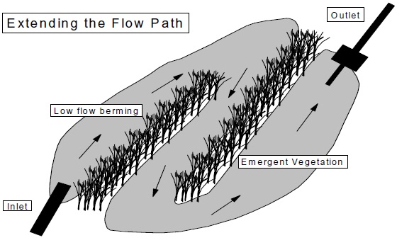
Permanent pool and active storage depths
The recommended depths for permanent and active storage are based on a variety of issues, including the potential for stratification of the water column and the tolerance of plants to water level fluctuations. In addition, some municipalities specify maximum allowable depths related to safety concerns. While technical guidance is provided below, the specific requirements of the local municipality should be checked.
The average permanent pool depth in a wet pond should be 1 to 2 metres. The maximum depth in a wet pond should be restricted to 3 metres, or preferably 2.5 metres. Although ponds deeper than 3 metres may have some benefits in terms of temperature, deep ponds will become stratified and the reduced oxygen content may create anoxic conditions releasing metals and organics from the pond sediments.
The maximum active storage depth (above the permanent pool) should be limited to 2 metres if the facility incorporates quantity control storage. Active storage depths of water quality or erosion control should be restricted to a maximum of 1.5 metres (preferably 1.0 metre) due to the extended drawdown times of these types of storage. This depth restriction is based on the inability of vegetation commonly planted along the perimeter of ponds to withstand water level fluctuations in excess of 1 to 1.5 m.
A 0.3 m freeboard should be provided above the design high water level.
Planting strategy
A planting strategy is required for any wet facility to provide shading, aesthetic, safety, bird control, enhanced pollutant removal, and other benefits. Section 4.6.1 describes the effective use of vegetation for these and other goals.
Fencing
The installation of full perimeter chain link fencing may be aesthetically undesirable. However, the use of permanent fencing is left to the discretion of the local municipality because of concerns for liability. Alternatives such as the strategic planting of thorn bearing trees and shrubs such as hawthorn and raspberry have proven very effective barriers. Fencing may be necessary in critical areas such as above headwalls or in other areas with significant changes in grade.
During the design stage, opportunities to incorporate amenities such as trails and seating areas around the SWMP should be explored to encourage safe public access and enhance the value of the facility within the community. Where barriers are required, the use of vegetation should be considered as the preferred option. The erection of temporary fencing may be required to mitigate access until thorny vegetation matures. Once a dense thicket is established, any fencing can be removed and the plant material alone will be sufficient to deter access over the long term.
Signs around the pond indicating the pond’s purpose and function also help to inform the public of the potential for water level fluctuations in the pond during storm events.
Grading
The grading and landscaping plan near the pond edges is important to ensure public safety and to maximize the functionality of the pond. Terraced grading (i.e., alternating steep and gentle slopes) is recommended to minimize the potential for any person to fall into the pond (Figure 4.20). Grading is critical at the permanent pool elevation. A minimum slope of 5:1 that extends at least 3 metres on either side of the permanent pool elevation is recommended. At the edge of the gentle grade in the permanent pool, small drops (150 mm - 300 mm) can be incorporated using logs or stones to warn people who gain access to the water that the pond is becoming deeper. Slopes in the extended detention portion of the pond should not exceed 3:1.
Figure 4.20: Wet Pond Grading and Planting Strategy
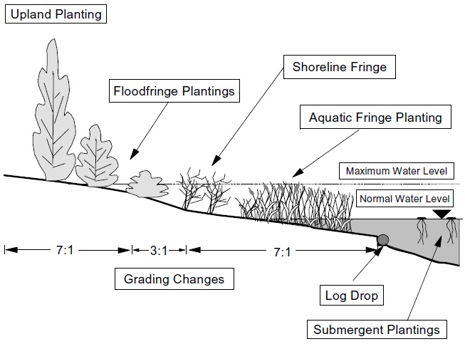
Grading is one of the simplest and most cost-effective tools available to enhance both the appearance and function of ponds, wetlands and hybrid facilities. The grading plan should be generated with the objective of achieving a facility with topography which blends with the surrounding landscape. The abandonment of planar grading and standard side slopes in favour of varied contour grading is fundamental to the creation of a facility that appears to fit within its context. The following principles should be applied to guide the generation of an effective grading plan:
- Design grading to blend with surrounding landform character;
- Employ a range of gradients to achieve objectives related to appearance, water quality improvement, biodiversity and recreational use;
- Design grading with a recognition of the requirements of the desired plant communities, notably soil moisture conditions, and frequency and duration of inundation;
- Configure grading to aid in the concealment of structures, including outfalls, maintenance access routes and weirs;
- Design landforms to increase the potential to establish shade over wet pond areas;
- Utilize islands and varied bathymetry to improve contact time and extend the length of the flow path; and
- Terrace wetlands to extend contact time, improve efficiency and mitigate the potential for short-circuiting.
Grading is a requirement in the construction of all stormwater management facilities, and consequently the implementation of landform grading is a technique that is easily adapted to ponds, wetlands and other types of facilities with minimal implication related to increased cost or complexity. The benefits which can be achieved through the application of this technique, however, are substantial.
Inlet configuration
The stormwater conveyance system (sewers, grassed swales) should ideally have one discharge location into the wet pond. This requires planning and ongoing interaction between land use planners and municipal engineers to ensure that it is technically feasible and economically efficient. Multiple inlets, although undesirable, may be required because of physical and economic constraints.
Exposed pilot channels (typically rock lined channels which convey stormwater from a pipe outlet to the pond) should be avoided. Monitoring has indicated that water temperature is increased 1°C for every 75 metres of pilot channel (Galli, 1990).
In areas where there is sufficient topographic relief, the inlet can be submerged below the permanent pool. This design has both advantages and drawbacks:
Advantages:
- safety and prevention of vandalism; and
- aesthetics.
Drawbacks:
- surcharging or backwater effect on the upstream stormwater conveyance system;
- scour/re-suspension of the pond bottom near the inlet;
- clogging of the inlet by sedimentation near the inlet; and
- sediment deposition in the upstream conveyance system.
A design which incorporates a submerged inlet requires a greater level of analysis at the design stage due to these potential drawbacks.
Submerged inlets should not be located at the bottom of the pond unless necessary. If the inlet is located at the pond bottom, a hard-bottomed surface near the inlet pipe is required to ensure that erosion and scour of the pond bottom do not occur. Other enhancements such as dissipation or deflection structures which direct flow away from the pond bottom also help to minimize scour and re-suspension of deposited sediment (Figure 4.21). Submerged inlets for piped systems with a flat grade (< 1%) should be avoided due to the potential for upstream surcharging. (As a rule of thumb only the last 10 metres of pipe should be submerged near the discharge point.)
Figure 4.21: Submerged Pond Inlet
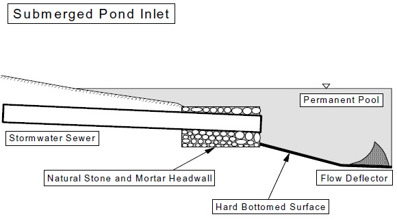
The effect of the tailwater condition produced by a partially submerged, or submerged, inlet must be assessed with respect to upstream surcharging during minor system and major system events. Major system events are analysed to determine the requirements for inlet controls on catchbasins. The effect of partial or complete submergence is best evaluated using a dynamic hydraulic routing model such as EXTRAN. A conservative steady state analysis can be made, however, by assuming a constant tailwater elevation equivalent to the maximum design water level in the pond and assessing the upstream surcharge for the peak design event flow.
Non-submerged (i.e., not submerged or partially submerged) inlets are generally easier to design since they do not introduce hydraulic complications into the system and are generally preferred over submerged inlets for the reasons described above (Figure 4.22).
Figure 4.22: Non-submerged Pond Inlet
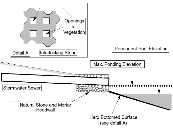
As a result of the raised inlet invert and pond side slopes, the non-submerged inlet will not discharge directly into water. It is important that any erosion potential between the inlet and the permanent pool be addressed. The inlet area should be deep (> 1 metre) to minimize concerns for re-suspension of settled pollutants.
To better integrate the design of the inlet structure within the aesthetics of a natural landscape, consideration should be given to replacing concrete headwalls and wing walls with retaining walls constructed of natural stone and plant material. These biotechnical structures provide the necessary stability and erosion protection while affording the following benefits:
- reduced cost;
- ease of construction;
- concealment of infrastructure; and
- habitat benefits.
The use of stone indigenous to the area helps to blend the facility into its physiographic context. Concrete aprons and chute blocks can be replaced with a plunge pool and planted outlet weir. The pool functions to dissipate energy and moderate velocities which in turn aid in limiting the re-suspension of accumulated sediments in the forebay. Plunge pools should be excavated to a greater depth than required and allowed to fill in and reshape to correspond with flow characteristics. Once this evolution of form has taken place, the plunge pool will maintain itself at the required depth. An outlet weir is used to control the water level in the plunge pool. Plant material is interlaced with riverstone to create a weir that is resistant to breaching and will accumulate trash and other floatables allowing more efficient removal.
Outlet configuration
The outlet should be located in the pond embankment for ease of operations, maintenance and aesthetics. There are two main designs which are currently accepted for the drawdown of the quality/erosion portion of the pond:
- a reverse sloped outlet pipe; and
- a perforated riser outlet pipe.
In combined facilities (incorporating quantity control), these types of outlet are usually combined with a weir structure which controls flow at the higher storage levels. Calculations of stage- outflow should account for flow capacity of both the weir and the water quality/erosion control outlet.
Similar techniques to those described for inlets can be employed to integrate outlet structures into the overall landscape of the stormwater management facility. Natural stone and plant material can be used in place of concrete and hard structures to improve aesthetics and achieve other related objectives. Planted weirs are effective in controlling flows at the outlet of sediment forebays. Seepage outlets which are designed to infiltrate water and facilitate the slow release of water to augment base flow in receiving watercourses or wetlands can be constructed utilizing a porous planted weir or hybrid structural/non-structural sand filter systems.
Reverse sloped pipe
A reverse sloped pipe (Figure 4.23) is appropriate for ponds with outlet areas ≥ 1 m deep. The reverse sloped pipe is used as the outlet in the water quality/erosion portion of the pond. It should drain to an outlet chamber located in the pond embankment. The outlet chamber can contain openings for flood control detention and overflow protection. It is recommended that a gate valve be attached to the reverse sloped pipe in the outlet chamber. This valve will allow the extended detention drawdown time to be modified to improve pollutant removal if the pond is found to be operating outside of the design criteria.
Figure 4.23: Reverse Sloped Pipe Outlet Configuration
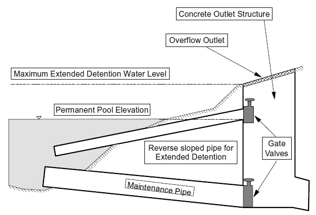
A low flow maintenance pipe should be provided to drain the pond for maintenance purposes. The maintenance pipe should also drain to the outlet chamber. It is recommended that the maintenance pipe be sized to provide a 6 hour detention time (6 hours was chosen as a reasonable time period in which to drain the entire pond for maintenance recognizing that the release rate should not affect the downstream receiving waters), and that a gate valve be attached to the end of this pipe in the outlet chamber.
Perforated riser pipe
A perforated riser pipe is the traditional outlet pipe that has been used historically throughout Ontario, although its use has diminished in recent years. The riser itself is perforated with holes. Typical hole diameters range from 12 mm to 25 mm.
The flow through the riser is controlled by an orifice plate located at the bottom of the riser structure. The smallest orifice diameter which should be used is 50 mm.
A design which is frequently used in Ontario incorporates a perforated riser pipe surrounded by a corrugated metal pipe standing on its end. Holes (50 mm diameter) are drilled in the metal pipe such that it acts as a riser. Stone is placed around the metal pipe (minimum 75 mm diameter) to act as a further filter. This design is shown in Figure 4.24.
Figure 4.24: Perforated Riser Pipe Pond Outlet Configuration
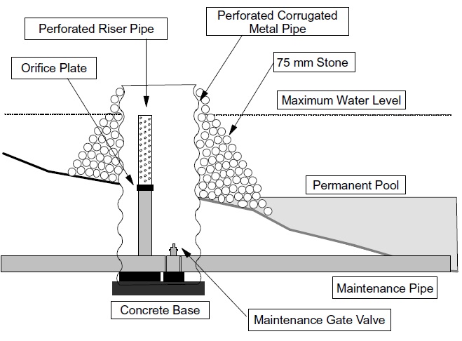
Although this design is inexpensive, and should be resilient to clogging by suspended solids, there are several drawbacks to keep in mind if this design is chosen:
- If the structure is not located in a chamber in the embankment it will have to be located in the pond itself. This type of outlet will look unnatural and is aesthetically unappealing;
- Corrugated metal pipe which has holes drilled in it will rust resulting in a shorter life span compared to other materials; and
- Since the riser is above the permanent pool it will be more susceptible to clogging by trash.
A similar outlet structure in the embankment (to address aesthetics and maintenance access) is provided in Figure 4.25.
Figure 4.25: Perforated Riser Outlet in Embankment
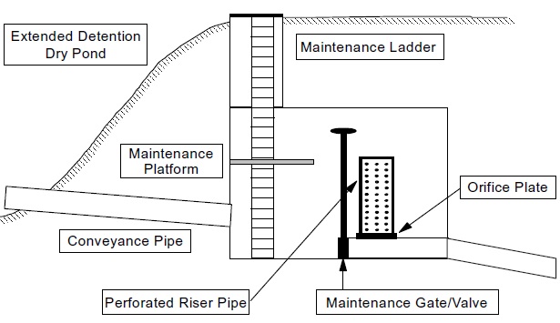
Water can be conveyed to the chamber by either a positively sloped pipe (> 1%) or a reverse sloped pipe (> 1%). If a positively sloped conveyance pipe is used, it should be larger than 250 mm diameter to minimize the risk of clogging.
The fittings and the riser itself should be constructed of a durable plastic or similar material. Holes should be drilled into the riser (13 mm - 25 mm diameter) along its entire length. The diameter of the pipe, and hence the number of openings, should be sufficient to ensure that the openings do not provide the extended detention control. The riser should be connected to the outlet pipe discharging from the chamber.
In the event that the riser does clog, there should be a maintenance gate or valve in the outlet chamber. A by-pass pipe which routes flows directly to the outlet pipe around the chamber is preferable, but more expensive.
Although the perforated riser outlet design has been used for wet ponds, it is best suited to ponds with a shallow permanent pool (i.e., wetlands) or to dry ponds.
Outlet channel
Most ponds which discharge directly to a stream will be in close proximity to the receiving waters (the pond will likely be located in the lowest section of the tableland adjacent to the receiving waters). The outlet channel in most of these cases will be short. In cases where the outlet channel is lengthy (i.e., traverses a wide floodplain), natural channel design techniques should be used to ensure that the channel conforms to the natural characteristics of the valleylands. Guidance on natural channel design techniques is provided in "Natural Channel Systems: An Approach to Management and Design" (Ministry of Natural Resources, 1994).
Winter operation
In areas of the province where ice cover persists into the spring, it is recommended that the volume of the permanent pool be increased by an amount equal to the expected volume of ice cover, as described in Section 4.3.
Because of concerns for winter operation, the minimum diameter of inlet pipes should be 450 mm. A slope of ≥ 1% should be used where possible. Submerged and partially submerged inlets should be avoided. Where a submerged inlet is required, its obvert should be located 150 mm below the expected maximum ice depth.
Submerged outlets (reverse sloped pipe, baffle plate) should be set 150 mm below the expected maximum ice level; reverse sloped pipes should have minimum diameter of 150 mm.
Maintenance enhancements
The practice of providing a hard-bottomed forebay has met with variable success. The hard-bottom design was originally intended to allow small machines (such as a backhoe) to operate with ease in scraping up sediment in a drained forebay. Experience has shown that the inter-locking blocks (most often used for bottom-hardening) will often be torn up by the scraping operation. Further, equipment such as long-reach backhoes have become more readily available for pond maintenance, and hence, there is less need for equipment entry into the pond. Therefore, unless some special condition warrants it, hardening of the forebay is no longer recommended.
Hardening of portions of the forebay (e.g., at a submerged inlet) to prevent erosion continues to be recommended.
The provision of a sediment drying area is a design enhancement which is desirable. However, the area needed for drying may be relatively large and may not be economically justifiable, especially given the expected frequency of clear-out after the development has stabilized. Further, equipment is available which can deal with high water-content sediments. Hence, a sediment drying area, while preferable, should only be incorporated into the design when it imposes no additional land requirement (such as when a public park abuts a SWMP facility and can be incorporated into the design).
4.6.3 Constructed wetlands
The constructed wetland is one of the preferred end-of-pipe SWM facilities for water quality enhancement. Wetlands are normally more land-intensive than wet ponds because of their shallower depth (both in the permanent pool and in the active storage zone). They are suitable for providing the storage needed for erosion control purposes, but will generally be limited in their quantity (i.e., flood) control role because of the restrictions on active storage depth.
The benefits of constructed wetlands are similar to wet ponds and include:
- the performance does not depend on soil characteristics;
- the permanent pool minimizes re-suspension;
- the permanent pool minimizes blockage of the outlet;
- the biological removal of pollutants (enhanced nutrient removal) occurs; and
- the permanent pool provides extended settling.
Constructed wetlands also have similar environmental impacts to wet ponds related to increased downstream water temperature which may limit their application in certain areas.
Limited performance monitoring has been conducted for wetland systems in Ontario, and constructed wetlands are the least understood end-of-pipe SWM facilities in terms of their biological impacts and enhancements. Although wetlands have been noted to accumulate total phosphorus, they export ortho-phosphorus (the form of phosphorus which results in algal blooms) and metals such as zinc during the fall as the wetland plants begin to decompose (Novotny, 1983; Martin, 1988; Bayley et al., 1986). These findings have given rise to the harvesting of wetland plant material to prevent the export of pollutants, while others argue that the release of contaminants (namely phosphorus) during the fall has a negligible impact on downstream resources.
Wetlands are used in Ontario for stormwater quality control and in some cases, as biological treatment facilities for other types of effluent. The latter type of facility requires a Schedule C Class EA, under the Municipal Class Environmental Assessment (2000). Although biological treatment occurs in constructed wetlands, physical processes, such as sedimentation and filtering, are the predominant removal mechanisms for most stormwater contaminants. Therefore, the Municipal Class EA requirements for stormwater treatment wetlands are equivalent to those for stormwater treatment ponds and infiltration systems.
Design guidance
A summary of design guidance is provided in Table 4.7. A more detailed discussion of this guidance is provided in the sections that follow.
| Design Element | Design Objective | Minimum Criteria |
|---|---|---|
| Drainage Area | Sustaining Vegetation; Volumetric turnover | 5 hectares, 10 hectares preferable |
| Treatment Volume | Provision of appropriate Level of protection (see Section 3.3.1.1) | As per Table 3.2 |
| Active Storage Detention Time | Suspended Solids Settling | 24 hrs (12 hrs if in conflict with minimum orifice size) |
| Forebay | Pre-treatment | Minimum Depth: 1 m, sized to ensure non-erosive velocities leaving forebay, maximum Area: 20% of total Permanent Pool |
| Length-to-Width Ratio | Maximize flow path and minimize short-circuiting potential | Overall: minimum 3:1, Forebay: minimum 2:1 |
| Permanent Pool Depth | Vegetation requirements, rapid settling | The average permanent pool depth should range from 150 mm to 300 mm |
| Active Storage Depth | Storage/Flow Control Sustaining Vegetation | Maximum 1.0 m for storms, < 10 year event |
| Side Slopes | Safety | 5:1 for 3 m above and below permanent pool, maximum 3:1 elsewhere |
| Inlet | Avoid clogging/freezing | Minimum 450 mm, preferred pipe slope > 1%, if submerged, obvert 0.15 m below expected maximum ice depth |
| Outlet | Avoid clogging/freezing | Minimum: 450 mm outlet pipe, preferred pipe slope > 1%, if orifice control used, 75 mm minimum, minimum 100 mm orifice preferable |
| Maintenance Access | Access for backhoes or dredging equipment | Provided to approval of Municipality, provision of maintenance drawdown pipe preferred |
| Buffer | Safety | Minimum 7.5 m above maximum water quality/erosion control water level |
In many cases the design elements for wetlands are the same as for wet ponds. In such cases, the reader is referred to Section 4.6.2. Figure 4.26 illustrates a constructed wetland.
Figure 4.26: Wetland with Forebay
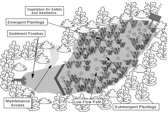
Drainage area
Wetlands require a minimum drainage area to sustain the aquatic vegetation and the permanent pool. As a general rule, wetlands should be implemented for drainage areas ≥ 5 hectares, and preferably 10 hectares or more. Smaller drainage areas may be viable when there is a high groundwater table or a source of make-up water.
Volumetric sizing
A subwatershed plan will provide guidance with respect to the permanent pool and extended detention storage required. If this guidance is not available, please refer to Chapter 3. Where erosion control active storage exceeds 40 m³/ha, the water quality active storage can be neglected (due to similar drawdown characteristics).
Active storage for quantity control will not usually be incorporated into a wetland design because of the practical limits imposed by the maximum allowable active storage depth (to protect wetland vegetation).
Sediment forebay
Sediment forebays (Figure 4.27) improve pollutant removal by trapping larger particles near the inlet of the wetland. A forebay is especially important in a wetland design since restricting maintenance to this area (for the most part) minimizes the need to disturb the wetland vegetation. The forebay should be deep (≥1 metre) to minimize the potential for scour and re-suspension. The forebay sizing depends on the inlet configuration, and several methods for sizing are provided in Section 4.6.2. In all instances, the forebay should not exceed one-fifth of the wetland surface area.
Figure 4.27: Wetland Forebay
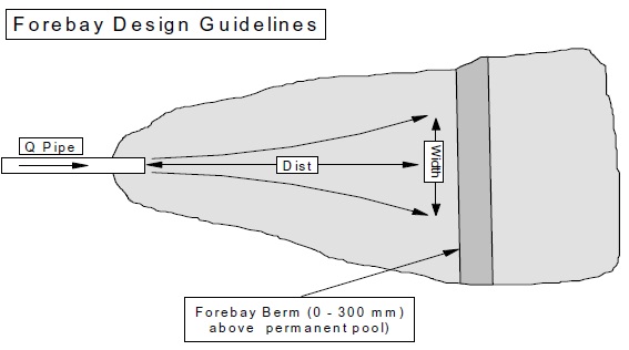
Forebay berm
The forebay should be separated from the rest of the wetland by an earthen berm. The berm should be set at the permanent pool elevation or extend into the extended detention portion of the wetland to act as a level spreader during storm events, and to minimize the disruption to the wetland during maintenance of the forebay. Flow calculations should be made under design conditions to ensure that the berm does not provide a flow restriction which would cause the whole forebay to overflow (not just into the wetland) because of the restriction of flow into the wetland resulting from a small berm width.
If a by-pass pipe is proposed to convey high flows around the wetland, a maintenance pipe should be installed in the forebay and connected to the by-pass pipe, if grades permit, to draw down the forebay for maintenance purposes.
The berm height should be set at, or within 300 mm of, the permanent pool elevation in the wetland. The berm should be planted with suitable emergent vegetation to promote the filtration of stormwater as it passes over the berm.
Detention time
Refer to Section 4.6.2.
Minimum orifice size
Refer to Section 4.6.2.
Length:width ratio
The flow path through a wetland is important to the overall performance of this SWMP. In contrast to the wet pond, however, the flow path in a wetland is mostly dependent on the plantings and grading within the wetland due to the shallow depth of the permanent pool. Although a length-to-width ratio of 3:1 is recommended in stormwater wetlands, it should be measured based on the flow path of low flows through the wetland rather than the overall dimensions of the wetland. Low flow paths should be created through the wetland to ensure that short-circuiting does not occur and that the flow path through the wetland is maximized during small events. Figure 4.28 illustrates the concept of maximizing the length of low flow paths.
Deep zones perpendicular to the direction of flow have also been suggested as a means of defeating short-circuiting. These zones collect and redistribute water, and also provide additional storage volume.
Permanent pool and active storage depths
The average permanent pool depth in a wetland should range from 150 mm to 300 mm. Inlet and outlet areas should be deeper (≥ 1.0 m) to minimize the re-suspension and discharge of settled pollutants from the facility. The maximum depth in the inlet and outlet areas should be restricted to 3 metres. The wetland design may incorporate deeper pools scattered throughout the wetland area. The deeper water areas will be mainly open water since they will be too deep to sustain emergent vegetation. As such, the deep areas in wetlands should be limited to 25% (Livingston, 1990) of the total surface area to ensure that the majority of the wetland sustains emergent vegetation.
Figure 4.28: Maximizing Wetland Flow Path
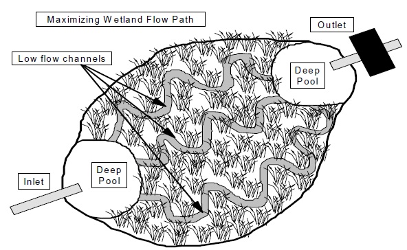
The maximum active storage depth should be limited to 1.0 metre. The depth restriction in the extended detention storage portion of the wetland is related to the planting strategy, since some plant species cannot withstand water level fluctuations in excess of 1 metre. Although the depth of 1 metre is appropriate as a generic value for most wetland designs, the depth of the extended detention storage should be based on the planting strategy that is chosen for the wetland. As such, an aquatic biologist should be consulted for the desired extended detention design depth based on the proposed planting strategy.
Where quantity control is provided, greater depths may be permitted for infrequent events (> 10 year return period).
Planting strategy
Refer to Section 4.6.1.
Fencing
Refer to Section 4.6.2
Grading
By the nature of the limited allowable permanent pool and extended detention depths, grading in a wetland should be reasonably flat. The side slopes near the permanent pool should be 5:1 or flatter. Slopes in the extended detention portion of the wetland should not exceed 3:1. Terraced grading (Figure 4.20) is recommended to minimize the potential for any person to fall into the wetland.
Grading should be designed to replicate natural landform with varied slopes and gradients. Undulating shoreline configurations are also an effective means to integrate the wetland into the landscape as a feature which is natural in appearance.
Inlet configuration
The stormwater conveyance system (sewers, grassed swales) should ideally have one discharge location into the wetland. This requires planning and ongoing interaction between land use planners and municipal engineers to ensure that it is economically efficient and feasible to drain the tributary area to one inlet location.
Exposed pilot channels (typically rock lined channels which convey stormwater from a pipe outlet to the wetland) should be avoided. Monitoring has indicated that water temperature is increased by 1°C for every 75 metres of pilot channel (Galli, 1990).
Inlets to wetlands will normally be designed to be non-submerged because of the shallow depth of the permanent pool (even if the forebay is deeper, winter freezing of the downstream shallow areas will normally preclude the use of a submerged inlet). Non-submerged inlets are generally easier to design since they do not introduce hydraulic complications into the system. The invert of the inlet pipe is set at the maximum design water level in the wetland (assuming no flow splitter (Section 4.7) upstream).
As a result of the raised inlet invert and wetland side slopes, the unsubmerged inlet will not discharge directly into water. It is important that the erosion potential between the inlet and the permanent pool be addressed in this design. The use of environmental stone/blocks (inter-locking blocks with large openings to allow vegetative growth in between the blocks) in this area is recommended (Figure 4.22) since they will minimize the erosion potential.
Outlet configuration
The outlet configuration options for a wetland are similar to those for a wet pond (refer to Section 4.6.2). In general, reverse sloped pipe configurations are recommended when the design incorporates a deep pool at the outlet. A perforated pipe riser is appropriate where a deep pool is not provided.
Winter operation
During the winter period, much of a wetland’s permanent pool volume will be frozen. The wetland will therefore behave in a manner similar to a dry pond, with its active storage component providing the only treatment. The design volumes provided in Table 3.2 ensure a substantial active storage volume relative to the permanent pool volume.
There are limited options for enhancing winter/spring performance in a shallow wetland. The forebay volume can be increased by the estimated volume of ice cover (see Section 4.3.1 for calculations of ice depth). Precautions can be taken to guard against freezing of pipes (Section 4.3.2). Where water quality control is desired during the winter/spring season, a hybrid wet pond/wetland design is often recommended (Section 4.6.4).
Maintenance enhancements
Refer to Section 4.6.2.
4.6.4 Hybrid wet pond/wetland systems
Hybrid wet pond/wetland systems consist simply of a wet pond element and a wetland element, connected in series. The system provides for the deep water component which will be least impacted by winter/spring conditions and the wetland component which provides enhanced biological removal during the summer months. In terms of land requirements, it falls between the amounts needed for wet ponds and wetlands.
Hybrid systems present a more diverse range of opportunities to achieve recreational, aesthetic and ecological objectives in the context of the open space system within a new community since they afford greater design flexibility and a diversity of landscape elements.
The design of a hybrid system should be based on the guidance provided for each element (i.e., wet ponds (Section 4.6.2) and wetlands (Section 4.6.3)), with the following clarifications:
- Volumetric sizing of the permanent pool should be based on the Hybrid Wet Pond/ Wetland SWMP type in Table 3.2. This assumes that the wet pond comprises 50% of the total permanent pool volume;
- A forebay is required for the wet pond (based on the size of the wet pond, not the entire system) but is not required for the wetland (the wet pond serves this purpose);
- Active storage depth restrictions for wetlands apply to the entire system, unless a terraced, overflow configuration is adopted;
- Detention time for the entire system should be targeted at 24 hours; and
- Length-to-width ratio for the wet pond element may be reduced to 2 to 1, although a higher ratio is encouraged.
4.6.5 Dry ponds
Dry ponds have no permanent pool of water. As such, while they can be effectively used for erosion control and flood control, the removal of stormwater contaminants in these facilities is purely a function of the detention time in the pond. For a 24 hour retention period, this normally means a lower contaminant removal (the inter-event settling time does not exist). Modelling studies (Perreault et al., Adams, 1996) have indicated that substantial improvement can be made in removal efficiency if a 48 hour detention time can be employed. While achieving this for smaller drainage areas can be difficult (because of orifice size considerations), the use of dry ponds in larger catchments (especially in retrofit situations) may have greater potential than had previously been thought. There are no documented performance monitoring data for dry ponds with longer detention times, however, and re-suspension of settled material remains a concern. As such, the use of dry ponds (for water quality control) remains largely restricted to retrofits, where temperature is an overriding concern, and situations where other more effective SWMP types are infeasible. Dry ponds may be used as part of an overall treatment train approach.
Design guidance
Figure 4.29 illustrates an extended detention dry pond. A summary of design guidance is provided in Table 4.8. A more detailed discussion of this guidance is provided in the sections that follow. Some of the design elements for dry ponds are the same as for wet ponds. In such cases, the reader is referred to Section 4.6.2. The design guidance provided is for continuous flow-through facilities, the most common form of dry pond. Dry ponds using real-time control or batch operation have been implemented (primarily in the Ottawa area), but most municipalities discourage their use.
Figure 4.29: Extended Detention Dry Pond with Forebay
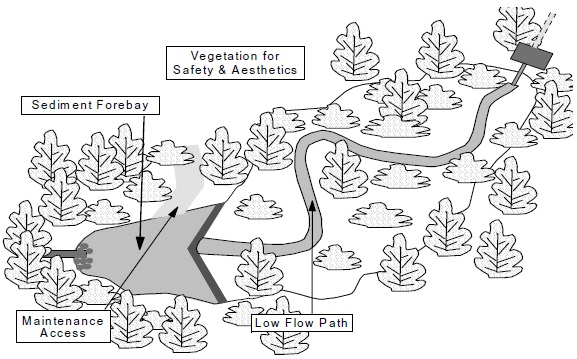
| Design Element | Design Objective | Minimum Criteria | Desired Criteria |
|---|---|---|---|
| Drainage Area | Minimum Orifice Size | 5 hectares | 10 hectares |
| Treatment Volume | Provision of appropriate Level of protection (see Section 3.3.1.1) | As per Table 3.2 | |
| Active Storage Detention Time | Suspended Solids Settling | 24 hrs (12 hrs if in conflict with minimum orifice size) | 48 hrs |
| Forebay | Pre-treatment | Minimum Depth: 1 m Sized to ensure non- erosive velocities leaving forebay | Minimum Depth: 1.5 m |
| Length-to-width Ratio | Maximize flow path and minimize short-circuiting potential | 3:1 (maybe accomplished by berms, etc..) | From 4:1 to 5:1 |
| Depth | Safety | Maximum Depth: 3 m, Mean Depth: 1 - 2 m | Maximum Depth: 2 m, Mean Depth: 1 - 2 m |
| Side Slopes | Safety | Grading of the side slopes terraced with an average slope of 4:1 or flatter | |
| Inlet | Avoid clogging/freezing | Minimum: 450 mm | Pipe slope > 1% |
| Outlet | Avoid clogging/freezing | Minimum: 450 mm outlet pipe. If orifice control used, 75 mm minimum (unless protected by a riser) | Pipe slope > 1%, minimum 100 mm orifice |
| Maintenance Access | Access for backhoes or bobcats | Provided to approval of Municipality | Provision of maintenance drawdown pipe in forebay |
| Buffer | Safety | Minimum 3 m above maximum water level |
Drainage area
As a general rule, dry ponds should be implemented for drainage areas ≥ 5 hectares. This area requirement is purely a function of the outlet sizing to ensure that the outlet does not become clogged. Smaller drainage areas may be considered (subject to minimum orifice sizing and, hence, reduced detention times) if the dry pond is used as part of an effective treatment train approach (e.g., more than just roof leader discharge to ground).
Volumetric sizing
A subwatershed plan, or alternatively Chapter 3, will provide guidance with respect to sizing. The larger of the erosion control active storage and the water quality active storage should be provided. Normally (unless 48 hour water quality detention is proposed), it is not necessary to provide both types of storage (due to similar drawdown characteristics).
Dry ponds are often used for flood control. The requirements for erosion control active storage will be dependent on local conditions and policies, as described in Chapter 3.
Sediment forebay
A sediment forebay facilitates maintenance and improves pollutant removal by trapping larger particles near the inlet of the pond. The forebay should include a deep permanent pool (> 1 metre) to minimize the potential for scour and re-suspension. The forebay sizing depends on the inlet configuration, and several methods for sizing are provided in Section 4.6.2.
Forebay berm
The forebay should be separated from the rest of the pond by an earthen berm. The berm should be designed as a small dam since the downstream section of the pond will be dry. A weir should be designed at the top of the berm to convey flows to the downstream section of the pond during storm events.
A maintenance pipe should be installed in the berm to allow the forebay to be drawn down for cleaning. This pipe would be opened and closed by a valve located on the upstream end of the pipe. Under normal operation, the valve would be closed such that the only means of conveyance would be the weir flow over the forebay berm. Flow calculations should be made to ensure that the berm does not provide a flow restriction which would cause the entire forebay to overflow (not just over berm) under design conditions because the berm does not provide adequate conveyance capacity. During maintenance periods, the valve would be opened allowing the forebay to be drained.
The berm should be planted with emergent vegetation to promote filtration of water as it passes over the berm.
Detention time
A minimum detention time of 24 hours should be targeted in all instances, unless the potential for clogging the outlet is high. Where possible, a detention time of 48 hours should be employed to improve suspended solids removal. In cases where the outlet is susceptible to clogging (i.e., drainage areas < 8 ha – see minimum orifice size), the detention time can be reduced to a minimum of 12 hours. The drawdown time in the pond can be estimated using Equation 4.10 (Section 4.6.2).
In cases where the outlet is susceptible to clogging (i.e., drainage areas < 8 ha – see minimum orifice size), the detention time can be reduced to a minimum of 12 hours. The drawdown time in the pond can be estimated using Equation 4.10 (Section 4.6.2).
Minimum orifice size
Refer to Section 4.6.2.
Length:width ratio
Refer to Section 4.6.2.
Active storage depth
The active storage depth should be limited to 2 to 3 metres. This maximum applies to all extended detention objectives (i.e., water quality, erosion and flood control). Depending upon the proposed planting strategy, these maximum depths may be reduced to 1 to 1.5 metres. It is anticipated, however, that the dry pond will not be actively planted in the extended detention portion due to harsh growing conditions (frequent wetting/drying).
Planting strategy
The planting strategy for a dry pond is less aggressive (i.e., fewer species and reduced planting intensity) than that for a wet pond. Plantings can be divided into three zones based on the soil moisture regime (frequency of inundation):
- extended detention area;
- flood fringe area (if the facility is a combined quality/quantity SWMP); and
- upland area.
Please refer to Section 4.6.1 for details. The growing conditions in the extended detention area for a dry pond are harsher than in the corresponding area of a wet pond since there is no influence from a permanent pool. Consequently, this area requires close attention to ensure that desirable plants become established.
Fencing
Refer to Section 4.6.2.
Grading
The grading in a dry pond is less critical than a wet pond since there is no permanent pool. Since water may be present in these facilities for 24 to 48 hours, it is recommended that the grading of the pond side slopes be terraced with an average slope of 4:1 or flatter.
Inlet configuration
The stormwater conveyance system (sewers, grassed swales) should minimize the number of discharge locations into the pond. The invert of the inlet pipe is set at the maximum design water level in the pond (assuming no flow splitter (Section 4.7) upstream). The use of environmental stone/blocks (inter-locking blocks with large openings to allow vegetative growth between the blocks) at the inlet is recommended to minimize the erosion potential (Figure 4.30). A flow deflector or energy dissipation blocks can be used to reduce the potential for scour of previously settled pollutants from the pond bottom.
Figure 4.30: Dry Pond Inlet
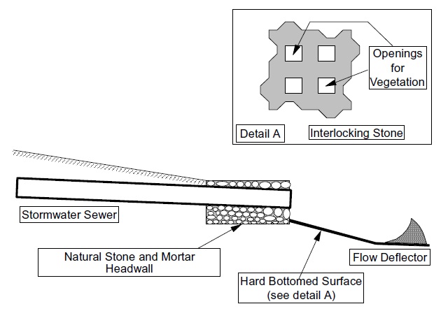
Outlet configuration
There are numerous outlet configurations possible for dry ponds. The outlet should be located in the pond embankment wherever possible for ease of maintenance and aesthetics. To illustrate typical designs, two configurations are presented: perforated riser and reverse sloped pipe.
A perforated riser pipe can be used as the outlet in the extended detention portion of the pond. As indicated in Section 4.6.2, a perforated riser pipe surrounded by a perforated corrugated metal pipe and 75 mm diameter stones can used. This outlet design is shown in Figure 4.24.
A second type of outlet configuration utilizes a reverse sloped pipe (Figure 4.31). In this design, a section of the pond near the outlet will not be gravity drained due to the reverse slope of the pipe. A portable pump must be used to drain this portion of the pond for maintenance. The use of under-drains (i.e., tile drains) under ponds has not been historically effective in draining these facilities and is not recommended.
Figure 4.31: Dry Pond Reverse Sloped Outlet Pipe
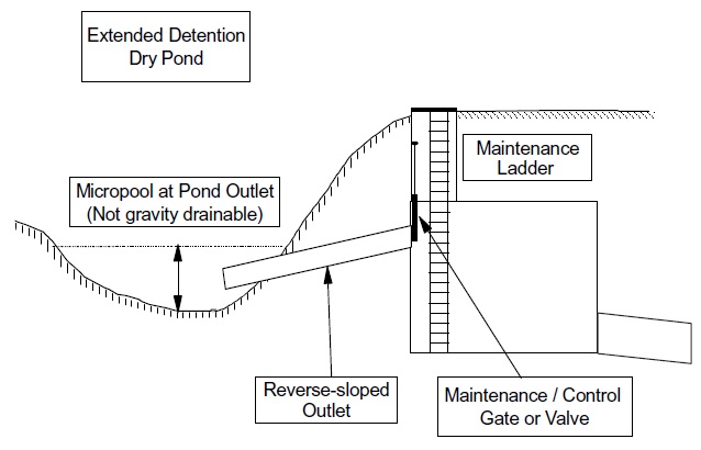
Experience with reverse sloped pipes indicates that they are resilient to clogging (Schueler, 1992). As such, the riser pipe and orifice connection are replaced by a gate valve or sluice gate on the reverse sloped pipe at the outlet chamber. If a valve is used, a gate valve is preferable to a globe valve given the size of valve required, and hence cost. This gate/valve will allow the manipulation of the outlet to achieve the desired settling characteristics in the field.
In addition, since the detention control is located on the inlet pipe to the chamber, rather than the outlet pipe from the chamber, the chamber can be used as a flood control outlet or emergency overflow outlet. For example, the inlet chamber can have a grated top, or weir openings along its side adjacent to the pond to provide further water management control.
Winter operation
Dry ponds are normally the least affected by winter/spring conditions because there is no permanent pool and the SWMP is not dependent on infiltration. Precautions can be taken to guard against freezing of pipes and orifices, and a by-pass (flow splitter) can be employed to limit inflow (and hence scouring of accumulated sediment) by major spring storms. Otherwise, dry ponds do not require special consideration of winter conditions.
Performance enhancement
The performance of a dry pond can be enhanced through the provision of a micropool at the outlet. The micropool is typically relatively shallow and undrained. Its purpose is to concentrate finer sediment and reduce re-suspension. The micropool is normally planted with hardy wetland species such as cattail.
4.6.6 Infiltration basins
Infiltration basins are above-ground pond systems which are constructed in highly pervious soils. Water infiltrates into the basin and either recharges the groundwater system or is collected by an underground perforated pipe network and discharged to a downstream outlet.
Design guidance
There is limited practical experience with infiltration basins in Ontario. A summary of design guidance is provided in Table 4.9, based on experience in other jurisdictions. A more detailed discussion of this guidance is provided in the sections that follow. Figure 4.32 provides an illustration of an infiltration basin.
Figure 4.32: Infiltration Basin
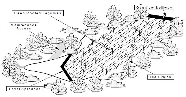
| Design Element | Design Objective | Minimum Criteria |
|---|---|---|
| Drainage Area | Infiltration | < 5 hectares |
| Treatment Volume | Provision of appropriate Level of protection (see Section 3.3.1.1) | As per Table 3.2 |
| Percolation Rate | Infiltration | ≥ 60 mm/hr |
| Depth to Water Table | Infiltration | > 1.0 m |
| Depth to Bedrock | Infiltration | > 1.0 m |
| Length-to-width Ratio | Spread inflow | 3:1 preferred |
| Storage Depth | Prevent Compaction | < 0.6 m |
| Pre-treatment | Longevity & Groundwater protection | Required, Redundancy (more than one device) preferred |
| By-pass | Winter/spring operation | Required |
| Maintenance Access | Access for light discing equipment | Provided to approval of municipality |
| Landscaping Plan | Enhance Infiltration Increase porosity | Grasses, deep rooted legumes |
Drainage area
Infiltration basins should be implemented for small drainage areas (< 5 ha). Although infiltration basins were originally designed to accommodate larger drainage areas, the monitoring which has been undertaken to date indicates that large scale infiltration is not feasible.
Land use
Infiltration basins are suitable for residential land uses. They are not recommended for industrial and commercial land uses where there is a high potential for groundwater contamination from chemical spills and maintenance (salting/sanding) activities.
Soils
Infiltration basins are not suitable where the native soil has a percolation rate of less than 60 mm/h. Typical percolation rates and soil types are provided in Table 4.4. Table 4.4 should be used as a screening tool to determine if a site may be suitable for an infiltration basin. If a site is acceptable based on the screening process, in situ percolation rates should be determined by a qualified soils specialist or hydrogeologist.
In areas where the soils are marginally acceptable, perforated pipes can be implemented to augment the drainage. Perforated pipes (100 mm diameter) which traverse the entire length of the basin should be spaced a maximum of 1.2 m apart and approximately 300 mm - 600 mm below the ground surface. The perforated pipes should drain to a collection pipe which discharges to an outlet pipe/structure.
Water table depth
The seasonally high water table should be more than 1 m below the bottom of the infiltration basin.
Bedrock depth
The bedrock should be more than 1 m below the bottom of the infiltration basin.
Volumetric sizing
In areas with a subwatershed plan, the plan will provide guidance with respect to sizing, otherwise, water quality treatment volumes are provided in Table 3.2. The larger of the erosion control active storage and the water quality active storage should be provided.
It is not recommended that flood control be provided in infiltration basins due to restrictions on allowable depth (to prevent compaction).
Storage configuration/depth
In an infiltration basin, surface storage is used to retain water for infiltration. In monitoring studies (Galli, 1990), one of the causal factors of failure was noted to be the depth of water retained in the basin. The weight of the water is thought to compact the basin decreasing its infiltration potential. The depth of storage should be limited to a maximum of 0.6 metres in order to minimize the compaction of the basin.
The length and width of the basin will be determined by the characteristics of the site in question (topography, size and shape). A desirable length-to-width ratio for an infiltration basin is 3:1 or greater. The appropriate minimum bottom area of the basin can be calculated based on Equation 4.3 with the porosity (n) set to 1.
Location/setbacks
Groundwater mounding calculations may be required to ensure that infiltration basins do not interfere with sewage system leaching beds. A hydrogeologist should be consulted with respect to the necessity for mounding calculations and the requirements for a setback from the tile field. It is anticipated that calculations will be required in areas where the soils are marginally acceptable for infiltration. Given the high percolation rates (≥ 60 mm/h) recommended for the implementation of infiltration basins, groundwater mounding generally should not be a problem.
The setbacks from wells specified in the Building Code for leaching bed systems should also be observed for infiltration basins.
Planting strategy
The vegetation in an infiltration basin should be able to withstand periods of ponding and maintain or enhance the pore space in the underlying soils. There is much literature to suggest that deep rooted legumes increase porosity and enhance infiltration compared to other ground covers (e.g., rotation of oat and corn crops with alfalfa) (Bryant et al., 1986; Minnesota Pollution Control Agency, 1989). As such, the planting strategy should include grasses and deep rooted legumes.
Pre-treatment
Effective pre-treatment SWMPs include wet ponds, dry ponds, and wetlands. Unfortunately, these are of limited use for small (< 5 hectare) drainage areas. For small drainage areas, sand filters, bioretention areas, vegetated filter strips, grassed swales or oil/grit separators should be used to pre-treat stormwater which discharges to an infiltration basin, especially if road runoff is treated. Source controls should also be investigated (e.g., sanding/salting practices, public education with respect to street/driveway sediments) in areas where an infiltration basin is proposed.
Overflow/by-pass
A by-pass flow path/pipe should be incorporated into the design of an infiltration basin to convey high flows around the basin. This will necessitate the construction of a flow splitter upstream of the basin (see Section 4.7). The by-pass may also function as:
- the normal outlet until the site is stabilized (inlet to the basin is blocked off);
- the normal outlet during basin maintenance; and
- the normal outlet during winter/spring conditions.
Construction
Infiltration basins will only operate as designed if they are constructed properly. There are three main rules that must be followed during construction:
- Basins should be constructed at the end of the development construction;
- Smearing of the native material at the interface with the basin floor must be avoided and/or corrected by raking or roto-tilling; and
- Compaction of the basin during construction must be minimized.
Technical effectiveness
The factors that contribute to failure of infiltration basins are:
- poor site selection (industrial/commercial land use, high water table depth, poor soil type);
- poor design (depth of ponding);
- poor construction techniques (smearing, over-compaction, basin operation during the construction period);
- large drainage area (high sediment loadings);
- lack of pre-treatment and/or by-pass; and
- lack of maintenance.
One of the main problems with centralized infiltration basins, like infiltration trenches, is that water from a large area is expected to infiltrate into a relatively small area. This does not reflect the natural hydrologic cycle and generally leads to problems (groundwater mounding, clogging, compaction).
As with other infiltration SWMPs, groundwater contamination and clogging of the basin are concerns. During the winter period, there will be an increased potential for clogging and groundwater degradation due to high sediment and salt loads. Pre-treatment and/or by-passing of winter flows may be required to address these concerns.
Infiltration basins should be designed with a by-pass system for large flows. Because of this requirement as well as the depth limitation to minimize soil compaction, infiltration basins are ineffective for water quantity control.
Infiltration basins may be incorporated in a stormwater management plan downstream from another end-of-pipe facility.
4.6.7 Filters
Filters are a relatively new type of end-of-pipe SWM facility for Ontario. They have been used extensively in parts of the United States with good success (Metropolitan Washington Council of Governments, 1992). Filters can be implemented above ground, or below ground as part of the storm sewer system infrastructure, and are generally intended for small drainage areas (≤ 5 ha). Filters are a water quality SWMP and have no practical application for erosion or quantity control. In many applications, filters discharge to the storm sewer system. However, direct discharge to a watercourse is possible where there is sufficient topographic relief.
Types of filters
Filters are versatile and come in many forms (Figures 4.33 to 4.37) including:
- surface sand filter;
- organic filter;
- underground sand filter;
- perimeter sand filter; and
- bioretention filter.
Surface and underground sand filters are the most common. Perimeter sand filters are especially useful around parking lots and because of their relatively large surface area, can be designed with lower head requirements. Organic filters can be designed as surface or subsurface devices. They employ a layer of peat in addition to the sand in order to enhance the removal of nutrients and trace metals. Filters using other media (such as iron filings) have also been used with some success. Bioretention filters are similar to conventional surface filters, but they allow the integration of open space and landscaping areas within the stormwater management facility.
Figure 4.33: Sand Filter Cross-section
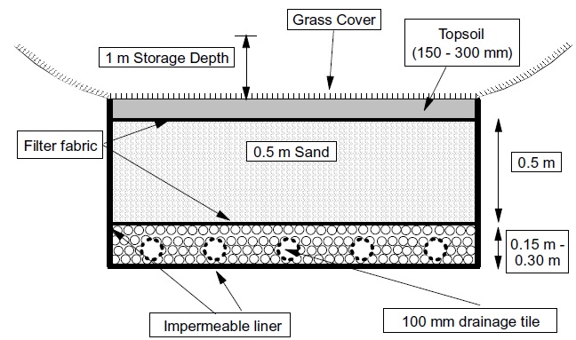
Figure 4.34: Peat Sand Filter Cross-section
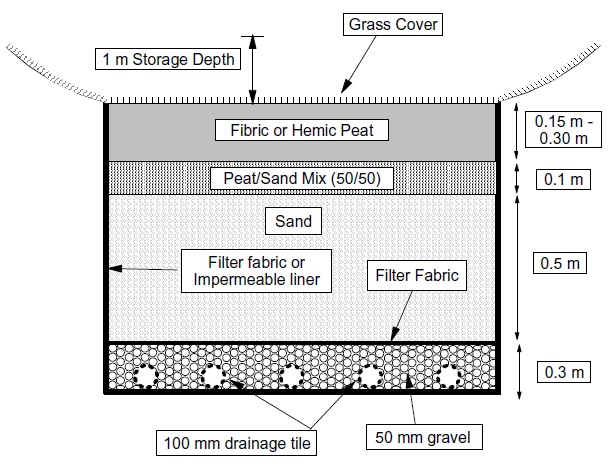
Figure 4.35: Underground Sand Filter
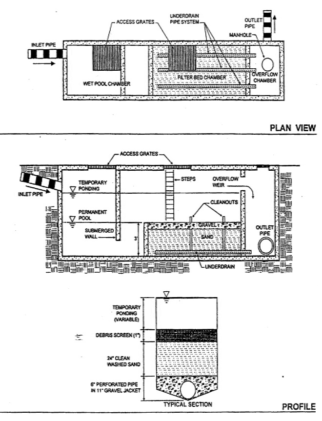
Source: Maryland Stormwater Manual, Volume 1, 1998
Figure 4.36: Schematic of a Perimeter Sand Filter
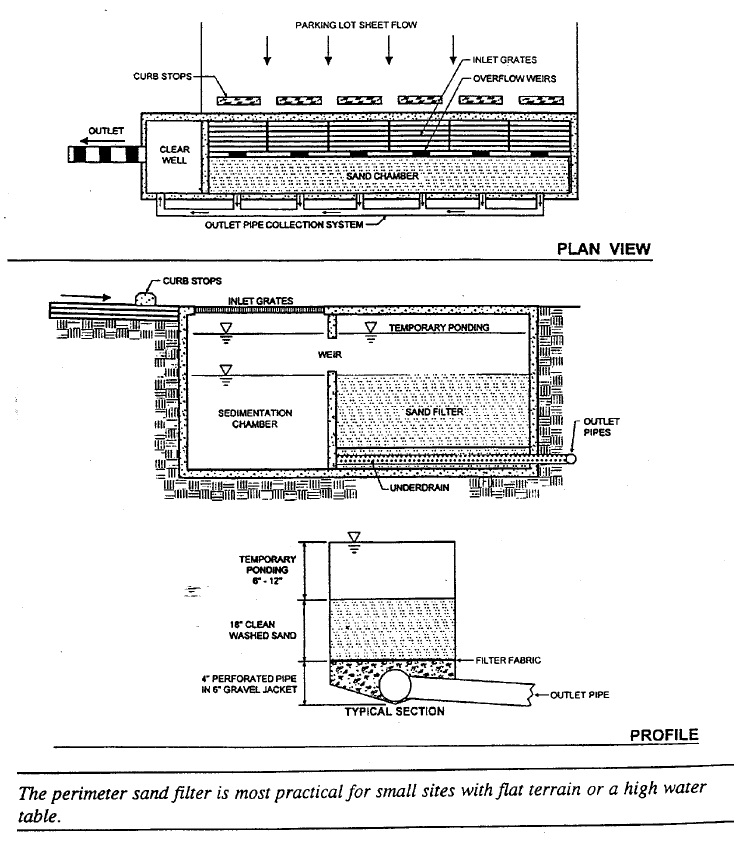
Source: Maryland Stormwater Manual, Volume 1, 1998
Figure 4.37: Schematic of Bioretention Filter
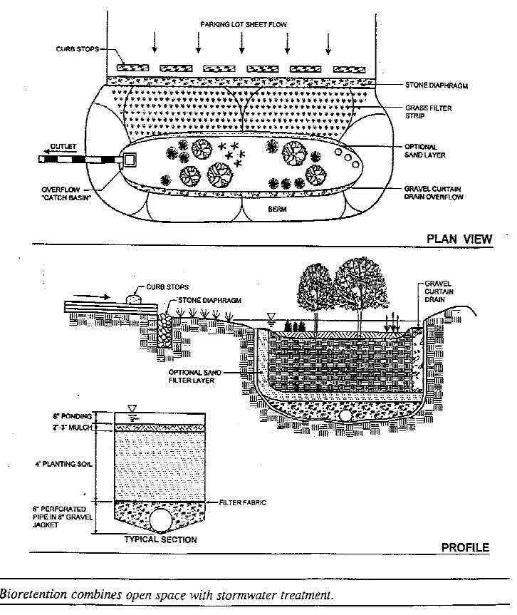
Source: Maryland Stormwater Manual, Volume 1, 1998.
Filtration systems can be incorporated into most parking lot areas or commercial sites. The surface of the biofilter can be landscaped using trees, shrubs and riverstone or turf and integrated as an amenity within the overall landscape for the development. Biofilters can also be located beneath hard surface landscaped areas, such as courtyards, walkways and patios.
Design guidance
There is limited operational experience with filters in Ontario. A summary of design guidance is provided in Table 4.10, based on experience in other jurisdictions. A more detailed discussion of this guidance is provided in the sections that follow.
| Design Element | Design Objective | Minimum Criteria | Preferred Criteria |
|---|---|---|---|
| Drainage Area | < 5 hectares | ||
| Treatment Volume | Provision of appropriate Level of protection (see Section 3.3) | As per Table 3.2 (infiltration) | |
| Pre-treatment | Longevity | Pre-treatment provided by sedimentation chamber or forebay, vegetated filter strip, swale or oil/grit separator | Sedimentation Chamber Volume:
|
| Storage Depth (head on filter) | Avoid filter compaction, Protect vegetation | Subsurface sand and organic filters: 0.5 m, Surface filters and bioretention: 0.15 m | |
| Filter Media Depth | Filtering |
|
|
| Under-drain | Discharge | Minimum 100 mm perforated pipes bedded in 150 mm - 300 mm of 50 mm gravel | Winter operation: minimum 200 mm perforated pipes bedded in 300 mm of 50 mm gravel |
Drainage area
Filters should be implemented for drainage areas ≤ 5 ha.
Land use
Filters may be employed for any land use, but because of their need for pre-treatment and ongoing maintenance, and the fact that they are not useful for erosion and quantity control, they are most often employed at commercial and industrial sites which have a high level of imperviousness. They can be designed to be part of the storm sewer system and thus can be combined with measures such as rooftop, parking lot or superpipe storage (for quantity control).
Volumetric sizing
Water quality volumes to be used in the design are provided in Table 3.2 under the "infiltration" heading. Erosion and quantity control volumes are not applicable to this type of SWMP. The design should be such that at a minimum, the by-pass of flows should not occur below or at the peak runoff from a 4 hour 15 mm design event.
Storage depth
It is recommended that the storage depth above a sand filter be limited to a maximum of 1 metre to reduce the potential for compaction of the sand layer. Storage depths for surface filters and bioretention areas should be limited to 0.15 m in order to protect the vegetation.
Media depth
The recommended filter layer depth for most sand filters is 0.5 m. In bioretention filters, the planting soil layer is normally 1.0 to 1.2 m.
Filter sizing
The area of the filter may be determined using the Darcy equation:
Equation 4.12: Surface Area of Filter
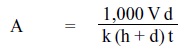
where:
- A
- surface area of the filter in m²
- V
- design volume(m³) derived from Table 3.2
- d
- depth(m) of the controlling filter medium (e.g., the sand or peat layer)
- k
- coefficient of permeability of the controlling filter media (mm/hr)
- h
- operating head of water on the filter(m)
- t
- design drawdown time in hours
Typical values for k are:
- Sand
- 45 mm/hr
- Peat
- 25 mm/hr
- Leaf Compost
- 110 mm/hr
Source: Maryland Stormwater Design Manual, Volume 1, 1998
Values of k for bioretention areas will depend upon the soil mix used and can be estimated from the particle size distribution. Drawdown time may range from 24 to 48 hours (24 hours is preferred).
Filter lining
Filters are most commonly constructed with impermeable liners or within concrete structures to ensure that native material does not enter the filter and clog the pore spaces, and to prevent the filtered water from infiltrating into the native soil (i.e., prevent groundwater contamination).
Sand filter discharge
Water which percolates through the sand filter is collected by pervious pipes and conveyed to the outlet. The pervious pipes should be a 100 mm diameter drainage tile laid at the bottom of a 150 mm - 300 mm layer of 50 mm diameter gravel. The drainage tile should be installed with a maximum spacing of 1.2 m. A layer of non-woven geotextile filter fabric should be installed between the sand layer and the gravel layer to minimize the potential for fines to clog the pore spaces in the gravel. The perforated pipes can be wrapped in non-woven filter fabric (filter sock) to prevent sand from entering the perforated pipe.
Organic filters
Organic filters most commonly include a layer of peat in the sand filter design. Peat has a high affinity for metals, nutrients and hydrocarbons, providing a greater level of water quality enhancement. The layer of peat is generally placed on top of the sand layer. The peat layer discharges to a peat-sand layer which provides a graduated increase in percolation to the sand layer. Fibric peat is recommended since it has a high percolation rate compared to more highly decomposed peats.
Pre-treatment
Pre-treatment is recommended for all filters. Ideally, a pre-treatment settling chamber should be incorporated into the design. The pre-treatment chamber should have a volume equal to 25% of the design water quality control volume. Other methods of pre-treatment include vegetated filter strips, grassed swales and oil/grit separators.
Overflow/by-pass
All sand filters should include an overflow or by-pass conveyance system. A by-pass system which routes flows around the sand filter is preferable to an overflow at the sand filter itself since there is no permanent pool in a sand filter to mitigate influent velocities. The influent pipe to the sand filter should be designed to accommodate the peak flow from a 4 hour Chicago distribution of a 15 mm storm.
Construction
Filters are very susceptible to clogging during the construction period. Therefore, construction practice should ensure that no runoff enters the filter until all contributing drainage areas have been stabilized (paved, vegetated, etc..).
Compaction can be a major problem in the construction of bioretention areas and may lead to failure of the facility. Where possible, excavation should be done with backhoes rather than loaders. Where loaders must be used, standard heavy construction equipment should be avoided in favour of light, wide-track or marsh-track equipment. Backfilling of the excavation with the planting mix should be done in 0.3 m or greater lifts. Light, wide-tracked or marsh-track equipment should be used for grading.
Winter operation
Surface filters and bioretention areas are generally subject to the same problems as surface infiltration devices. Subsurface filters, while less susceptible than surface filters, also suffer in performance because of freezing in underdrain pipes or the filter medium. Filters which utilize organic media are particularly prone to freezing because they retain water.
Filters commonly receive runoff from parking areas and roads which are subject to sanding and salting. Pre-treatment is essential to avoid problems with clogging of the filter medium.
Most filter systems can be designed to operate seasonally using a by-pass. Where this is not done, it is recommended that the following measures be implemented in order to improve filter performance during cold weather:
- Increase underdrain pipes to a minimum of 200 mm diameter and slope at more than 1%;
- Flow controls and by-passes should be designed using weirs (rather than standpipes) where possible;
- Designs should include an oversized pre-treatment chamber (equivalent to 50% of the design treatment volume); and
- For surface filters or bioretention areas, runoff should be conveyed through a vegetated filter strip or swale (at least 5 m in length) prior to entering the filter area.
Maintenance
Removal of accumulated sediment from the pre-treatment chamber should be conducted regularly (at a minimum, when the accumulation depth exceeds 0.3 m). Silt/sediment should be removed from the surface of the filter when 2-3 cm has accumulated or when the drawdown time increases beyond 20% of the design value. The upper layer of the filter material (e.g., 0.1 to 0.15 m) should be removed and replaced with clear material when accumulated sediment is removed from the filter.
Technical effectiveness
Filters are a relatively new type of end-of-pipe SWM facility for Ontario. They have been used extensively in parts of the United States with good success (Metropolitan Washington Council of Governments, 1992).
Filters are effective in removing pollutants, resistant to clogging (if pre-treatment is provided) and are generally easier and less expensive to construct/retrofit than infiltration trenches. Pre-treatment and longevity are critical factors that may vary from design to design. It is therefore recommended that they be used for pre-treatment, post-treatment, and in terms of water quality control that they be implemented as part of a multi-component approach. Filters are a water quality SWMP and have no practical application for erosion or flood control.
4.6.8 Oil/grit separators
Oil/grit separators (OGS) are used to trap and retain oil and/or sediment in detention chambers, usually located below ground. They operate based on the principles of gravity-based sedimentation for the grit, and phase separation for the oil. There is minimal attenuation of flow in oil/grit separators since they are not designed with extended detention storage. Like filters, they have no infiltration capability.
Separators are often used as spill controls, pre-treatment devices or end-of-pipe controls as part of a multi-component approach for water quality control. They are typically used for small sites but sizing and design are dependent on the function they are to fulfil. Whether separators are to be used as pre-treatment devices or in the overall design as a part of a multi-component system, it is essential to select appropriate equipment based on their demonstrated capabilities. There have been numerous applications of OGS since the 1980's and there are a variety of both proprietary and non-proprietary oil/grit separators on the market ranging from chambered designs to manhole-types.
Design guidance
Many suppliers provide design guidance specific to their products. This guidance is normally application-dependent. The designer should be fully aware of the assumptions and methodology used in formulating performance predictions as they may have implications for the design. The application and design should be discussed with approval agencies.
Oil/grit separators are typically used for small drainage areas (< 2 hectares). As a spill or grit control device, they are particularly well-suited to conditions where space is constrained. Since the majority of spills are small in volume and are not weather dependent, separators provide an effective means of control. Oil/grit separators are beneficial for industrial and commercial sites, and large parking areas or transit facilities where there is a higher risk of spills and a greater opportunity for sediment build-up. OGS are also often used to provide an inspection access as part of a storm sewer discharge control program (e.g., sewer use by-law). Typical applications include:
- automobile service station parking areas;
- selected areas at airports;
- some industrial or commercial areas;
- pre-treatment for other SWMPs;
- infill/retrofit developments;
- areas susceptible to spills of material lighter than water (bus depots, transfer stations); and
- inspection structures for private industrial or commercial sites that drain to the municipal sewer system.
Many end-of-pipe stormwater practices benefit from pre-treatment, typically in the form of pre-settling in pond forebays or settling chambers, or biofiltration in swales, vegetative filter strips or sand filters. Pre-treatment can also be provided by oil/grit separators. Separators are particularly well suited for use with subsurface SWMPs without pre-treatment chambers incorporated into their design. The benefits of pre-treatment include the extension of the operational life of stormwater management facilities adversely impacted by sediment, the extension of maintenance intervals and the prevention of oil sheen.
For stormwater quality control, oil/grit separators may be applied as one element of a multi-component approach unless it is determined that it can achieve the desired water quality as a stand-alone device on a site-specific basis. In a multi-component approach there is a series of stormwater quality measures for water quality improvement. A multi-component approach can often be expected to provide a higher level of improvement.
Potential applications of oil/grit separators may be for water quality control for re-development projects in an urban core or stormwater quality retrofits for an existing development. However, in new residential developments where space is not as constrained, the selection of SWM practices may be governed by having to meet erosion and flood control objectives as well as water quality objectives.
Oil/grit separators generally form part of the underground storm sewer infrastructure. Their use is typically not as constrained by space considerations, bedrock or groundwater levels, or soil conditions (although they have foundation bedding requirements similar to manholes and underground tanks).
Winter operation
There is relatively limited data on the effects of cold weather and winter runoff on the performance of oil/grit separators. Depending on the depth and location of the installation, separators may be susceptible to freezing, which will reduce or eliminate their effectiveness (e.g., by causing more frequent by-pass or overflow). Designs that retain water between events may also be susceptible to salt stratification resulting in short-circuiting and reduced detention times and removal rates. Further studies are needed to verify the impacts of salt stratification on different OGS designs. In the interim, more frequent maintenance (e.g., removal of retained water) may be employed during the winter months to enhance performance.
Technical effectiveness
There have been many refinements to existing designs of oil/grit separators and new designs have come to the market. Research and monitoring of many of the devices has been conducted by manufacturers of the devices and government agencies. The reported results have been quite variable (both excellent and very poor) and appear to be highly dependent on study design, specific site conditions, sizing of the device relative to the contributing drainage area, particle size distribution and the varying flow conditions under which the tests were conducted. The higher removal efficiencies generally corresponded to the presence of high percentages of sand or heavy sediments in the stormwater or lower flows into the separator. Therefore, if reported results are to be used as a reference, comparable factors should be thoroughly considered.
It is noteworthy that a key factor in assessing the performance of OGS is the level at which by-pass occurs. A by-pass is generally provided for OGS as discussed in section 4.7. Under conditions of high stormwater flow, the overall solids removal efficiency of the separator usually decreases since the stormwater which is by-passed receives no treatment. Oil/grit separators will be required to be sized to capture and treat at least 90% of the runoff volume that occurs for a site on a long-term average basis for water quality objectives of 'enhanced protection.' For water quality objectives of 'normal protection' and 'basic protection,' at least 85% of the total runoff volume that occurs for a site will be required to be captured and treated. In each application, the facilities are still required to meet the water quality objectives of long-term average removal of 80%, 70% and 60% of suspended solids in the total runoff volume for 'enhanced,' 'normal' and 'basic' protection levels, respectively. Suspended solids removal efficiency is to be calculated based on 100% of the total runoff volume for all the storm events that occur for the site on a long-term average basis. For example, for a site that requires a normal level of protection (70% suspended solids removal) with a facility that only captures 85% of the runoff volume, the facility would have to achieve a performance of 82% suspended solids removal for that 85% of the volume. The average efficiency would be 70% = (85% of the volume × 82% efficiency) + (15% of the volume × 0% efficiency).
The multi-component approach has been confused in the past with the term "treatment train." In the multi-component approach, a series of stormwater quality practices are used to meet water quality objectives. The treatment train approach is premised on providing control at the lot level and in conveyance followed by end-of-pipe controls. A treatment train is required to meet the multiple objectives of water balance, water quality, and erosion and flood control in an overall stormwater management strategy. Lot level and conveyance controls can reduce end-of-pipe storage requirements for erosion control and are the best means of achieving water balance objectives. Water quality improvement and quantity control for small storms are secondary benefits. End-of-pipe controls are required to meet water quality, and erosion and flood control objectives in most circumstances.
4.7 Flow splitters/by-passes
While many stormwater facilities are designed to meet multiple objectives (e.g., water quality, erosion control, quantity control), some SWMP designs are intended for water quality control only. In such cases, the design capacity of the SWMP will normally be less than the capacity of the stormwater conveyance system. It is often necessary to by-pass larger flows in order to prevent problems with the SWMP (e.g., re-suspension of sediment) or damage to the facility (e.g., compaction of soil, etc..). Flow splitters are used to direct the runoff from a water quality storm into an end-of-pipe SWM facility, but by-pass excess flows from larger events around the facility into another SWMP or directly into the receiving waters. As a general rule, flow splitters are generally provided for:
- extended detention dry ponds (without a forebay);
- constructed wetlands (without a forebay);
- infiltration trenches/basins;
- oil/grit separators; and
- filters.
Most Ontario municipalities will not accept mechanical/electrical controls on stormwater management facilities due to the potential for operational and maintenance problems associated with numerous real-time control systems within a municipality’s jurisdiction. Therefore, the preferred flow splitter design operates on hydraulic principles.
The design of a hydraulically operated flow splitter must account for backwater conditions in the SWM facility, the hydraulic potential into the facility at the design by-pass rate, and the potential for flow reversal during the recession limb of a storm.
Design guidance
The typical flow splitter design is shown in Figure 4.38. Water is conveyed to the SWM facility via a first flush pipe. Once the facility reaches its design capacity, water backs up in the influent pipe and, hence, the flow splitter itself. As the water level reaches the by-pass elevation, stormwater begins to by-pass the SWM facility. The by-pass is generally accommodated by a weir in the flow splitter structure.
Figure 4.38: Storm Sewer Flow Splitter
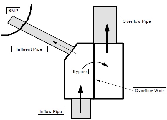
The by-pass elevation, by-pass capacity and influent pipe capacity dictate how the flow splitter will operate.
By-pass elevation
There are two main methods for setting the by-pass elevation. The first is to set the by-pass elevation such that the design storm is captured at the maximum by-pass rate. Using this method, the design water level in the end-of-pipe SWM facility would be equal to the depth of water in the by-pass structure necessary to achieve the maximum anticipated by-pass rate. Although this ensures that the maximum design water level in the SWM facility is never exceeded, it also causes the by-pass to operate for storms smaller than the design event.
The second method is to set the by-pass elevation equal to the design storage elevation in the end- of-pipe SWM facility. Using this method, the facility will only start to by-pass once it has captured the design runoff volume. Although this ensures that the design volume will be captured before by-pass occurs (given the influent pipe capacity is not exceeded), it also means that the water level in the SWM facility will exceed the design level for large infrequent storms which utilize the by-pass. This method is preferred since it is conservative. An example of the operation of this type of flow splitter is provided in Figure 4.39.
By-pass capacity
Given that the by-pass elevation is set equal to the design storage elevation in the end-of-pipe SWM facility, the maximum elevation in the facility depends on the rate of by-pass with depth. For example, it would be ideal (from a hydraulic perspective) to have a long by-pass weir, such that a small depth increment resulted in a large flow (and very little increase in depth in the facility). However, large weirs result in large flow splitter structures which are expensive. Therefore, an optimum balance between depth increase and by-pass design should be sought recognizing that the increase in storage depth due to a flow splitter is not prolonged.
In end-of-pipe SWM facilities with only an extended detention outlet, the flow splitter has the potential to cause flow reversal. Flow reversal is the flow of water out of a SWM facility via the flow splitter structure. Flow reversal has the potential to occur when the flow over the by-pass subsides quickly while the flow out of the pond is governed by a slow extended detention release. In these instances, water levels in the facility above the by-pass elevation can force water back into the flow splitter and over the by-pass structure during the recession limb of a by-pass storm.
In order to minimize flow reversal, several guidelines can be followed:
- provide an overflow outlet above the design water level in the SWM facility;
- minimize the depth of by-pass to achieve the desired by-pass rate; and
- maximize the head losses between the facility and the by-pass to minimize the hydraulic potential into the SWM facility.
It should be recognized, however, that the provision of an overflow outlet will result in more water being conveyed into the pond, which defeats the original purpose of the flow splitter. Therefore, the provision of an overflow outlet is not recommended as a standard practice to minimize flow reversal.
The operation of the by-pass must be assessed for the design event used to size the upstream pipe network. This event will vary from municipality to municipality (2 year, 5 year, 10 year storm). In some cases, the upstream pipe network will be oversized due to overland flow constraints and may convey the 100 year storm. In all cases, the splitter operation during the pipe design event must be assessed.
Figure 4.39: Operation of a Hydraulic Flow Splitter
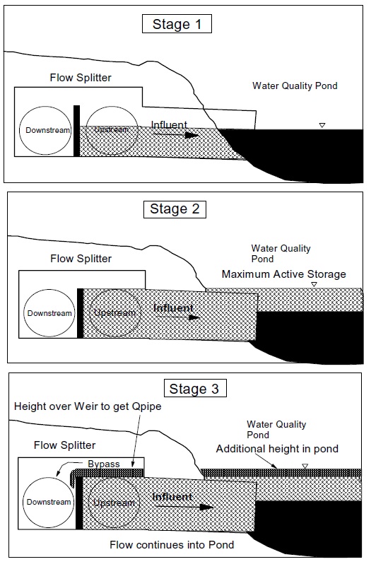
Influent pipe capacity
The capacity of the influent pipe into the SWM facility determines when a by-pass occurs for intense storms, and it adds to the head loss between the by-pass and the pond (this determines the hydraulic potential into the pond once the by-pass begins to operate).
The design of the influent pipe depends on the intensity of the water quality storm in question. Event simulations of a 2 hour Chicago distribution of a 25 mm storm produce peak flows which are similar to a 2 year storm (Note: A 25 mm storm can be a 100 year event if it occurs in a very short time-frame.) Since the design inflow is supposed to be representative of a frequent event, the 2 hour distribution is overly conservative. It is recommended that a 4 hour Chicago distribution be used to determine a peak flow for the sizing of the first flush pipe.
In pond systems, this will equate to the peak flow from a 25 mm storm. A 15 mm storm should be used for end-of-pipe infiltration systems and filters, and a 10 mm storm should be utilized for vegetated filter strips.
Maintenance by-pass
In cases where the facility accommodates high flows as well as low flows, a flow splitter is not required. A maintenance by-pass is recommended, however, to facilitate maintenance operations in the urban SWMP if conventional "in-the-dry" maintenance techniques are to be used. Such a by-pass is not needed if the intention is to use hydraulic dredging or other "wet" techniques in maintenance.
The by-pass can be provided by a second pipe in a manhole upstream of the SWMP itself. The second pipe would be closed/blocked during the normal operation of the pond. During the maintenance periods, the inlet to the pond would be closed and the maintenance pipe opened. The maintenance pipe could either discharge to an overland flow path around the SWMP, or to the outlet via an underground pipe system. If water is conveyed to the SWMP by swale, a separate maintenance swale must be constructed around the SWMP from the pond inlet, and the design must incorporate movable gates to re-direct flows into the maintenance swale during maintenance periods.
4.8 Major/minor system design
Stormwater management includes recognition and design of the major and minor systems (Figure 4.40). The minor system conveys frequent runoff events while the major system conveys infrequent runoff events. The major and minor systems exist for pre- and post-development conditions, whether designed or not.
Generally, the division between the major and minor systems in urban areas is defined by municipal or township standards. Standards define the location within road allowances, the materials of construction, the physical dimensions of the common drainage elements (i.e., curb heights, catchbasins, road slopes, lot grading, etc..), and the procedures to be employed in sizing storm sewer or ditches. Not all urban areas have been designed employing a major/minor system approach. In some municipalities, only the minor system has been designed while the major system has evolved.
Figure 4.40: Major/Minor Systems
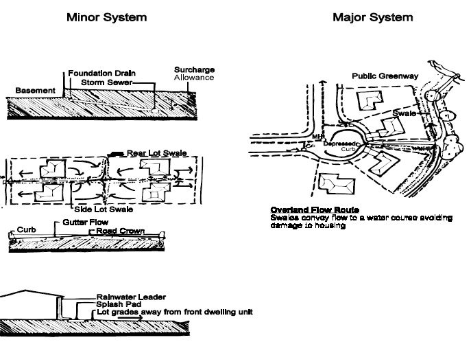
Source: Urban Drainage Design, Ontario Ministry of Natural Resources, Ministry of the Environment et al, 1987
For pre-development conditions, the minor system is defined as the stream or low flow portion of the watercourse. The floodplain can be viewed as the major system. The division between major and minor systems is a function of the hydrologic processes that occur within the watershed. Many factors including topography, vegetation, geology, groundwater and meteorology define the low flow and floodplain capacities of a watercourse.
Stormwater management systems reflect the physical characteristics of the development that it supports whether the development land use is residential, commercial, industrial or transportation. Well-designed drainage systems require a set of criteria that will mitigate potential natural, economic and social environment impacts.
Good design ensures the following:
- That upstream runoff is conveyed through the development with minimal impacts to upstream people, properties and natural environments;
- That site runoff is conveyed to a secure outlet with minimal impacts to the development site users and property; and
- That site runoff has minimal impacts on downstream people, properties and natural environments.
For the development site, drainage design objectives include protecting property from surficial flooding, protecting basements from surcharge or backwater flooding, and street drainage is designed for convenience and conveyance. Criteria or standards are generally defined by the municipalities and townships that assume drainage, sewage and road works for new development.
4.8.1 Minor system
For urban areas, the minor system is composed of lot grades, ditches, backyard swales, roof leaders, foundation drains, gutters, catchbasins, and storm sewers. Traditionally, minor systems have been designed to reduce the inconvenience to the public from runoff events.
Sewer sizing
Each municipality will set the standards for the sizing of storm sewers. Generally, storm sewers are sized to convey runoff from storms with return periods ranging from 2 years to the 10 years. The storm sewers are sized to convey frequent events and prevent nuisance flooding. Most municipal standards will set a minimum diameter to prevent siltation and clogging. Minimum storm sewer sizes are approximately 250 mm diameter.
The Rational Method (Equation 4.8) is the most commonly used method to determine peak flow rates to be conveyed by the storm sewer system. The parameters utilized in the Rational Method are usually defined by the municipality or township. Generally, the capacity of storm sewers is determined using Manning’s equation.
Roof downspouts
Roof downspouts should discharge to lawns to encourage infiltration.
Catchbasin inflows
The total storm sewer inflows from catchbasins and roof leaders should be determined to prevent surcharging of the storm sewer system and possible basement flooding. Controls can be placed in catchbasins to reduce inflows to the full flow capacity of the storm sewer system.
Catchbasins do not catch 100% of the road flow. As the road flow increases, the top width of flow becomes greater than the width of the catchbasin grate. Water will either by-pass or overshoot the catchbasin grate. As a result, runoff will continue down the road to the next catchbasin. For low flows, catchbasins will capture approximately 80 to 100% of the gutter flow. For high flows, approximately 70% of the road flow will by-pass the grate.
Catchbasin spacing
Catchbasins are usually placed at low points within the road system. The catchbasins are spaced to prevent gutter/road flow from by-passing the catchbasin grate.
Maximum sewer capacity
The storm sewer reaches maximum capacity when the critical depth of flow is equal to the storm sewer diameter. Increasing the storm sewer slope beyond the critical slope will not increase the storm sewer capacity. The critical slope will be a function of the peak flow rate, the roughness of the storm sewer and the storm sewer diameter.
Maximum and minimum flow velocities
Flow velocities should be limited to approximately 6 m/s, while minimum flow velocities should exceed 1 m/s. Slower flow velocities will tend to deposit silt and sediment.
Basement flooding
Each municipality will have criteria to prevent basement flooding for new urban development. The following are generic criteria:
- Minimum lot grades, i.e., 2%;
- Minimum 1% swale slopes at lot boundaries;
- Basement floor elevations above the 100 year hydraulic gradeline in the storm sewer system;
- Basement floor elevations above the backwater level in the minor system produced by the Regulatory Flood in the major system;
- Basement floor elevations above high groundwater levels;
- Building invert opening elevations above the maximum site ground elevation; and
- Foundation drain collectors not susceptible to backwater or surcharging, etc..
4.8.2 Major system
For urban areas, the major system includes natural streams, valleys, swales, artificial channels, roadways, stream road crossings and ponds. The major system conveys runoff from infrequent events that exceed the minor system capacity. The major system will exist whether it has been designed or not. For good design, the major system will reduce the risk to life and property damage by providing overland flow routes to a safe outlet. Most flow routes will follow the natural topography.
Although the primary of function of roads is to convey vehicular traffic, roads can be used to convey runoff. Standards for using the roadway as a floodway are set by the local municipality. The following are general criteria:
- On arterial roads, the depth at the crown shall not exceed 0.15 m;
- On local roads, flow should not overtop the curbs;
- On collector roads, 1 lane should be left free from flooding;
- On arterial roads, 1 lane should be left free from flooding in each direction;
- Flow should not cross roads except for minor storms;
- Low points along the road grade should not exist unless the low points are conveying flow to the major system;
- The product of flood depth at the gutter multiplied by the flow velocity shall be less than 0.65 m²/s; and
- At regular intervals along the road, major storm runoff should be conveyed to a watercourse or a major channel.
4.9 Modelling techniques
Lot level and conveyance controls result in reductions in the quantity of runoff which must be treated by end-of-pipe controls. Stormwater modelling (provided in support of development applications) can reflect these reductions. Event modelling for sizing end-of-pipe flooding controls should also recognize and incorporate end-of-pipe storage provided for quality and erosion control. Table 4.11 summarizes modelling approaches which may be used, and further detail is provided in the sections which follow. Guidance is also provided in terms of reductions in the volumetric requirements provided in Table 3.2. It should be noted that any change in storage requirements with respect to Table 3.2 represents a reduction in the volume of active storage required (not permanent pool).
| SWMP | Water Quality Benefit: Event Modelling | Water Quality Benefit: Table 3.2 | Flooding Benefits: Event Modelling | Erosion Benefits: Event Modelling |
|---|---|---|---|---|
| Lot Grading | increase pervious depression storage for lot areas by 0.5 mm for every 0.5% reduction in lot grade from 2% | water quality active storage reduced by 5 m³/ha for every 0.5% reduction in lot grade from 2% | increase pervious depression storage for lot areas by 0.5 mm for every 0.5% reduction in lot grade from 2% | increase pervious depression storage for lot areas by 0.5 mm for every 0.5% reduction in lot grade from 2% |
| Roof Leader Ponding | model roof areas separately, increase impervious depression storage by (ponding volume/roof area) | water quality active storage reduced by Σ, ponding volume (m³) which cannot exceed that required to store runoff to the ponding area | model roof areas separately, increase impervious depression storage for roof areas by (ponding volume/roof area) | model roof areas separately, increase impervious depression storage for roof areas by (ponding volume/roof area) |
| Roof Leader Soakaway Pits | model roof areas separately increase impervious depression storage by (volume of voids in pit/roof area) or model pits as reservoirs (route flow to pits using reservoir routine) | water quality active storage reduced by volume of voids in soakaway pit which cannot exceed that required to store runoff to the pit | model roof areas separately increase impervious depression storage by (volume of voids in pit/roof area) or model pits as reservoirs | model roof areas separately increase impervious depression storage by (volume of voids in pit/roof area) or model pits as reservoirs |
| Pervious Pipes | route flow through a DIVERT HYD or similar routing routine to divert exfiltrating flows based on orifice calculations. Exfiltrated flows should be routed through a reservoir based on feasible trench sizing with overflows added back into the pipe | water quality active storage reduced by exfiltration media storage | route flow through a DIVERT HYD or similar routing model to divert exfiltrating flows based on orifice calculations. Exfiltrated flows should be routed through a reservoir with overflows added back into the pipe | route flow through a DIVERT HYD or similar routing model to divert exfiltrating flows based on orifice calculations. Exfiltrated flows should be routed through a reservoir with overflows added back into the pipe |
| Pervious Catchbasins | route water quality event using a reservoir routine based on feasible catchbasin size | water quality active storage reduced by pervious catchbasin storage | route water quantity events using a reservoir routine based on feasible catchbasin size and evaluate incidental benefits | route erosion event using a reservoir routine based on feasible catchbasin size and evaluate incidental benefits |
| Infiltration Trench | route water quality event using a reservoir routine based on feasible trench sizing | water quality active storage reduced by infiltration trench storage | route water quantity event using a reservoir routine and evaluate incidental benefits | route erosion event using a reservoir routine and evaluate incidental benefits |
| Enhanced Grass Swales | route water quality event using a reservoir routine | water quality active storage reduced by enhanced grass swale storage | route water quantity events using a reservoir routine based on enhanced grass swale design | route erosion event using a reservoir routine based on enhanced grass swale design |
| Vegetated Filter Strip | route water quality event using a reservoir routine with a weir outlet to size storage based on the allowable weir flow depth | n/a | size vegetated filter strip based on water quality event and evaluate incidental benefits during water quantity storm | size vegetated filter strip based on water quality event and evaluate incidental benefits during the erosion storm |
| Wet Pond | route water quality event using a reservoir routine and size storage to obtain desired detention time | water quality active storage reduced by wet pond active storage | route quantity events with erosion/quality reservoir routine and size quantity storage | route erosion event using water quality reservoir routine and size erosion storage |
| Dry Pond | route water quality event using a reservoir routine and size storage to obtain desired detention time | water quality active storage reduced by dry pond storage | size dry pond based on quality and evaluate incidental benefit during quantity storms | route erosion event using water quality reservoir routine and size erosion storage |
| Dry Pond with forebay | route water quality event using a reservoir routine and size storage to obtain desired detention time | water quality active storage reduced by dry pond storage | route quantity events with erosion/quality reservoir routine and size quantity storage | route erosion event using water quality reservoir routine and size erosion storage |
| Wetland | route water quality event using a reservoir routine and size storage to obtain desired detention time | water quality active storage reduced by wetland storage | size wetland based on quality and evaluate incidental benefit during quantity storms | route erosion event using water quality reservoir routine and size erosion storage |
| Wetland with Forebay | route quality event using a reservoir routine and size storage to obtain desired detention time | water quality active storage reduced by wetland storage | route quantity events with erosion/quality reservoir routine and size quantity storage | route erosion event with quality reservoir routine and size erosion storage |
| Sand Filter | route water quality event using a reservoir routine and size storage to prevent overflows | water quality active storage reduced by sand filter storage | size filter based on quality and evaluate incidental benefits during quantity storms (route quantity event through filter) | route erosion event using reservoir routine based on filter size and evaluate incidental benefits |
| Infiltration Basin | route water quality event using a reservoir routine based on feasible basin sizing | water quality active storage reduced by infiltration basin storage | size basin based on feasibility and evaluate incidental benefits from basin during quantity storms | route erosion event using water quality reservoir routine and size erosion storage |
*The storage provided by stormwater lot level and conveyance controls may be reduced by a longevity factor(see text for further detail) when assessing end-of-pipe SWM facility storage requirements for water quality, quantity and erosion.
4.9.1 Reduced lot grading
Recommended lot grading changes include the provision for a typical standard slope (2 - 5%) within 2 - 4 metres of any buildings and a flatter slope (< 2%) for the remaining lot area. These grading changes are only appropriate if the site is naturally flat.
Water Quality, Erosion and Flood Control Storage Requirements Based on Modelling Event modelling using an altered pervious depression storage will account for the effect of the flatter grading on the required end-of-pipe water quality, quantity and erosion storage. The water management benefit derived from these grading changes given a typical lot (12 m frontage by 30 m depth) is estimated to be an additional 0.5 mm of pervious depression storage for every 0.5% reduction in the typical 2% grading standard (i.e., 1.5% grade = +0.5 mm, 1.0% grade = +1 mm, 0.5% grade = +1.5 mm).
The depression storage can be further adjusted based on a "longevity factor" which takes into account public acceptance and landowner alterations to individual site grading (Equation 4.13). It is recommended that a longevity factor of 0.75 be used for developments that implement reduced lot grading.
Equation 4.13: Adjusted Pervious Depression Storage
DSP = 4.67 + (2 – G) × f
where:
- DSP
- previous depression storage(mm)
- G
- 0.5%(lot grading)
- f
- 0.75(longevity factor)
A higher or lower factor could be requested by a regulatory agency (municipality, MNR, MOE, CA) based on the agency’s experience with people altering site grading patterns. There is a tendency for people to make minor alterations.
Water quality storage requirements based on table 3.2
The effects of reduced lot grading on the water quality storage requirements presented in Table 3.2 can be estimated by Equation 4.14.
Equation 4.14: Lot Grading Adjustment
V = (A – LL) × S + LL × [ S – (( 2 – G ) × 10 × f )]
where:
- V
- volume of water quality storage required (m³)
- A
- total development area (ha)
- LL
- development area with flat lot grading (ha)
- S
- orignal water quality requirement from Table 3.2 (m³/ha)
- G
- lot grading(%)
- f
- longevity factor
If the second term on the right hand side of Equation 4.14 is negative (i.e., more storage is provided by the reduced lot grading than is required), it should be set to zero. The development area with reduced lot grading (LL) should not include the road right-of-ways.
4.9.2 Roof leader discharge to surface ponding areas
Water quality, erosion and flood control storage requirements based on modelling the benefits from discharging roof leaders to on-site surface ponding areas can be estimated by altering the impervious depression storage for rooftop areas
The change in impervious depression storage depends on the volume of surface ponding provided and the roof area being controlled. Equation 4.15 provides an estimation of the adjusted impervious depression storage. The use of Equation 4.15 implies that the roof areas will be modelled separately since the impervious depression storage of driveways and roads should not be altered.
Equation 4.15: Impervious Depression Storage
DSI = (SPV ÷ RA) × 1,000 × f
where:
- DSI
- adjusted impervious depression storage(mm)
- SPV
- volume of surface ponding storage (m³)
- RA
- rooftop area (m²)
- f
- longevity factor
The longevity factor in Equation 4.15 accounts for the public acceptance of local ponding areas on their property. It is recommended that a longevity factor of 0.75 be used for surface ponding storage for rooftop leader discharges.
Water quality storage requirements based on table 3.2
The effects of surface storage for roof leader discharges on the water quality storage requirements presented in Table 3.2 can be estimated by Equation 4.16.
Equation 4.16: Roof Leader Surface Storage Adjustment
V = [(A – RS) × S ] + [( RS × S) – ( SPV × f )]
where:
- V
- volume of water quality storage required(m³)
- A
- total development area (ha)
- RS
- rooftop area + surface ponding area(m²)
- S
- water quality requirement from Table 3.2(m³/ha)
- SPV
- volume of surface ponding storage(m³)
- f
- longevity factor
If the second term on the right hand side of Equation 4.16 is negative (i.e., more surface storage is provided for runoff to the ponding area than is required), it should be set to zero. The rooftop area as defined in Equation 4.16 includes the surface storage area (and surface drainage tributary to the ponding area).
4.9.3 Roof leader discharge to soakaway pits
Water quality, erosion and flood control storage requirements based on modelling
The water management benefit from the implementation of soakaway pits can be determined by adjusting the impervious depression storage using Equation 4.15 and the method described in Section 4.9.2. The term SPV (surface ponding volume) would be replaced with the volume of void space in the soakaway pit (e.g., 40% of the gravel storage volume with 50 mm gravel).
Another method to calculate the benefit of soakaway pits with respect to water quality, erosion and quantity control is to model them as reservoirs. The areas with soakaway pits would be lumped together and modelled separately. The flow from this area would be routed through a reservoir. The outflow rate from the reservoir would depend on the configuration of the pit and the volume of water it contains. A rating curve can be calculated based on the storage and flow rate as shown in Equation 4.17. It is recommended that the longevity factor be based on the percolation rate of the surrounding soils due to the lack of widespread experience with the implementation of soakaway pits. Table 4.12 provides recommended longevity factors based on native soil percolation rates.
Equation 4.17: Soakaway Pit Rating Curve
Q = f × (P ÷ 3,600,000) × (2LD + 2WD + LW) × n
(Rating Curve Storage Volume)
V = LWD × n × f
where:
- Q
- flowrate(m³/s) for a given storage volume (V)
- f
- longevity factor
- P
- native soil percolation rate(mm/h)
- L
- length of the soakaway pit(m)
- W
- width of the soakaway pit(m)
- D
- depth of water in the soakaway pit(m)
- V
- volume of water in the soakaway put(m³)
- n
- void space in the soakaway put storage layer
| Soil Percolation Rate (mm/h) | Longevity Factor (f) |
| < 25 | 0.5 |
| > 25 but < 100 | 0.75 |
| > 100 | 1 |
Water quality storage requirements based on table 3.2
The effect of soakaway pits for roof leader discharge on the water quality storage requirements presented in Table 3.2 can be estimated using Equation 4.16. The term SPV (surface ponding volume) would be replaced with the volume of void space in the soakaway pit (e.g., 40% of the gravel storage volume with 50 mm gravel).
4.9.4 Pervious pipes
Water quality, erosion and flood control storage requirements based on modelling
The benefits provided by the implementation of pervious pipes with respect to water quality, erosion and quantity storage are more difficult to quantify since the exfiltration is dependent on many factors (pipe slope, number of perforations, size of perforations, depth of flow). Paul Wisner and Associates (1994) indicated that the exfiltration can be reasonably modelled using the orifice equation with a variable orifice coefficient. The coefficient varies from 0 to a maximum of 0.63 depending on the perforation size and depth of flow. However, this calculation must be performed along the pipe as water flows through the system since water is continuously exfiltrating.
The results from the Wisner study were used to derive a steady state equation for the rate of exfiltration with flow through the pipe. The exfiltration rate for any given flow in a pipe can be approximated using Equation 4.18. This equation indicates that the exfiltration rate depends on the inflow rate, the size and number of perforations along the pipe and the slope of the pipe. The results for Equation 4.18 were compared to the laboratory tests performed in the above-noted study. The simplified relationship is less accurate than continuous simulation. However, it provides a reasonable approximation of the pipe flow – exfiltration relationship.
Equation 4.18: Exfiltration Discharge
Qexft = (15A - 0.06S + 0.33) Qinf
where:
- Qexft
- exfiltration flow through pipe perforations (m³/s)
- A
- area of perforations/m length of pipe (m²/m)
- S
- slope of perforated pipe(%)
- Qinf
- flow through the perforated pipe(m3/s)(longitudinally)
Equation 4.18 was developed based on the measured flows in a 300 mm diameter pipe with 12.7 mm and 7.9 mm perforations. The use of Equation 4.18 for larger diameter pipes, or pipes with much larger perforations, should be scrutinized.
Based on equation 4.18, a rating curve can be estimated for the exfiltration flow as a function of flow in the perforated pipe system. Using this relationship, a hydrograph diversion routine (such as DIVERT HYD in OTTHYMO) can be used to determine the split in flows that are conveyed by the perforated pipe system.
The diverted flows that represent exfiltration should be further routed through a reservoir routine based on the exfiltration storage, and native material. Equation 4.17 can be used to determine the routing reservoir rating curve for the exfiltrated water. The term "2 W D" in Equation 4.17 should be set to zero in this application since the exfiltration storage is a linear system. The overflows from the reservoir signify that the exfiltration storage is full, and should be added back to the pipe flow. This can be accomplished using a second DIVERT HYD command.
Water quality storage requirements based on table 3.2
If Table 3.2 is used, the volume of exfiltration storage can be compared directly with the infiltration storage required to achieve the desired level of water quality protection for the appropriate level of imperviousness. The required infiltration storage should be adjusted based on the longevity factor (Table 4.12).
4.9.5 Pervious catchbasins
Water quality, erosion, and flood control storage requirements based on modelling
The benefit with respect to water quality, quantity and erosion control resulting from the installation of pervious catchbasins can be estimated using the same methodology as that derived for soakaway pits (i.e., reservoir routing using Equation 4.17). The modelling of pervious catchbasins is easier than soakaway pits since the lot and road areas do not have to be separated into different basins.
Water quality storage requirements based on table 3.2
The effects of pervious catchbasins on the water quality storage requirements presented in Table 3.2 can be estimated by Equation 4.19.
Equation 4.19: Pervious Catchbasin Adjustment
V = (A × S) - (CBV × f)
where:
- V
- volume of water quality storage required(m³)
- A
- development area draining to pervious catchbasins (ha)
- S
- water quality requirements from Table 3.2(m³/ha)
- CBV
- volume of pervious catchbasin storage (m³)
- f
- longevity factor
The longevity factor should be estimated from Table 4.12.
4.9.6 Sand filter
The sizing of a sand filter for water quality control is based on the runoff to be treated (either from Table 3.2 or the runoff from a 15 mm storm) and the filtration area.
Water quality, erosion and flood control storage requirements based on modelling
The outflow from the sand filter should be based on Equation 4.20.
Equation 4.20: Sand Filter Discharge
Q = f × (P ÷ 3,600,000) × (LW × n)
where:
- Q
- flowrate(m³/s) out of the sand filter
- f
- longevity factor
- P
- percolation rate for sand (mm/h)
- L
- length of the filter(m)
- W
- width of teh filter(m)
- n
- void space in teh sand filter (typically 0.25)
Only the length and width (bottom area) are used in Equation 4.20 since the assumption is made that the filter is contained within an impermeable liner causing all of the discharge to be collected in the perforated pipes at the bottom of the filter.
The longevity factor in Equation 4.20 should be based on the percolation rate of the sand used from Table 4.12.
In order to assess the incidental benefits of sand filters in reducing erosion and flooding storage requirements, the sand filters should be modelled using a reservoir routine. An assumption of constant outflow with increasing storage can be made as a conservative assumption. Some marginal increase in flow will have to be assumed with increasing storage recognizing the mathematical instabilities inherent in most reservoir routines. The rating curve above the water quality storage volume should reflect conveyance without attenuation to simulate the by-passing of the filter.
Water quality storage requirements based on table 3.2
The volume of storage provided by the filter should be adjusted using the longevity factor (Table 4.12) based on the filter media and may be compared directly with the water quality storage requirements in Table 3.2.
4.9.7 Infiltration trenches
The sizing of an infiltration trench is based on the runoff to be treated (either from Table 3.2 or the runoff from a 15 mm storm) recognizing that a smaller size may be implemented based on the physical constraints imposed by the site.
Water quality, erosion and flood control storage requirements based on modelling
The same methodology used for sand filters to account for incidental flooding and erosion benefits can be used for infiltration trenches. The assumption of using the bottom area of the trench is still reasonable since the infiltration trench has a sand filter layer for pollutant removal (i.e., the trench should be designed to convey water through the bottom).
The percolation rate (P) and longevity factor (f) in Equation 4.20 should be assessed for the native material below the infiltration trench recognizing that the surrounding native material will be the limiting conveyance media. The porosity in Equation 4.20 should be equal to the void space in the storage media (0.4 for clear stone). The rating curve above the water quality storage volume should reflect conveyance without attenuation to simulate the by-passing of the trench.
Water quality storage requirements based on table 3.2
The volume of infiltration storage provided by trench should be adjusted using the longevity factor (Table 4.12) based on the native material and may be compared directly with the storage required in Table 3.2.
4.9.8 Enhanced grass swales
Water quality, erosion and flood control storage requirements based on modelling
Enhanced grass swales have a permanent check dam to hold back water during small events. The check dam acts as a weir during larger events and can be modelled as a reservoir. The rating curve for the reservoir can be determined based on the stage storage relationship upstream of the check dam in the swale and the weir equation (Equation 4.4). Given the small storage volume contained in one swale, and the likelihood for numerous swale areas, the storage volume from several swales should be lumped together in this assessment (i.e., downstream check dam controls lumped storage).
In order to ensure that numerical instability does not occur in the routing routine, there should be a positive discharge from the swale as the storage increases (even below the elevation of the check dam). The discharge from the swale below the elevation of the check dam can be calculated using Equation 4.20 where the term LW represents the contact area between the water and the swale (i.e., the wetted perimeter of the swale below the check dam). The percolation rate (P) in Equation 4.20 should be assessed for the native soil material and the porosity should be set to 1.
The longevity factor for enhanced grass swales should be 1.0 since they are not directly dependent on infiltration for operational performance.
Water quality storage requirements based on table 3.2
The effects of enhanced grass swales on the water quality storage requirements presented in Table 3.2 can be estimated by Equation 4.19. The term CBV would be replaced with the storage provided upstream of the enhanced grass swale at the elevation of the check dam.
4.9.9 Vegetated filter strip
Water quality, erosion and flood control storage requirements based on modelling
The sizing of the level spreader is based on the conveyance of the peak flow rate from a 10 mm (4 hour Chicago storm) with a depth of less than 100 mm based on the weir equation (Equation 4.4). If a short spreader is utilized there may be a need for storage upstream of the level spreader to ensure that flow depths through the vegetated filter strip do not exceed 100 mm. A reservoir routine can be used to assess the water quality storage required upstream of the level spreader.
If there is appreciable storage designed upstream of the level spreader, the incidental flood and erosion control benefits from the vegetated filter strip can be assessed using the reservoir routine (the vegetated filter strip should not be designed specifically for erosion and flood control). In most cases, however, it is expected that the level spreader will be designed such that there is minimal upstream storage required. It should be assumed that there are no flood and erosion control benefits resulting from the implementation of a vegetated filter strip under these conditions.
4.9.10 Wet pond
The benefits with respect to erosion and flooding from the implementation of water quality storage in a wet pond are easily calculated. The required water quality storage (either from Table 3.2 or the Subwatershed Plan) can be modelled as a storage reservoir in an event model. The values in Table 3.2 are based on a 24 hour detention. Additional points can be added to the reservoir to simulate erosion control (if different from water quality control) and flood control. This methodology can be used if quality, quantity and erosion are accommodated in the one pond. Multiple reservoir routines can be implemented for separate facilities. Figure 4.41 illustrates the zones in a combined quality and quantity wet pond. It is noteworthy that in many instances the water quality control zone may be eliminated since its function is served by the erosion control zone (e.g., each have similar drawdown times – typically 24 hours).
Figure 4.41: Multiple Objective Pond Outlet
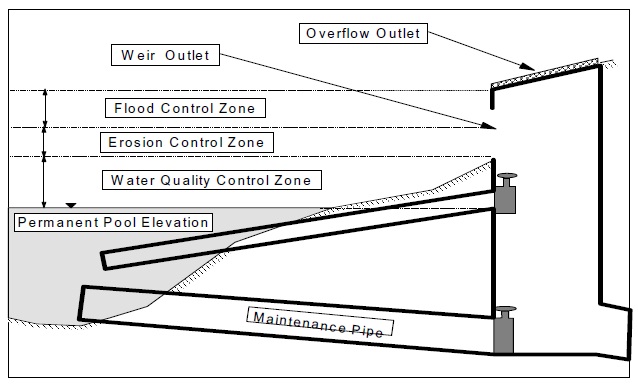
4.9.11 Dry pond
A dry pond should not be used for combined quality and quantity control unless a forebay is included in the design due to the potential for re-suspension and scour of previously settled pollutants. The benefits with respect to erosion and flooding from the implementation of water quality storage in a dry pond which incorporates a forebay are calculated in the same manner as for a wet pond.
4.9.12 Wetland
A wetland should not be used for combined quality and quantity control unless a forebay is included in the design due to the potential for re-suspension and scour of previously settled pollutants. The benefits with respect to erosion and flooding from the implementation of water quality storage in a wetland which incorporates a forebay are calculated in the same manner as for a wet pond.
4.9.13 Infiltration basin
The assessment of incidental flooding and erosion control benefits derived from the implementation of an infiltration basin is identical to that for an infiltration trench. The bottom area of the basin in Equation 4.20 represents the contact area of water and the basin floor. As such, a reservoir routing rating curve can be developed based on the grading in the basin (i.e., stage-storage-contact area relationship) and Equation 4.20 (with the porosity set to 1). The rating curve above the water quality storage volume should reflect conveyance without attenuation to simulate the by-passing of the basin.
4.10 New environmental technologies
As the "state-of-the-art" of stormwater management evolves there will be new technologies not discussed in this manual. For the evaluation and assessment of new environmental technologies, the Ministry has a program called the New Environmental Technology Evaluation (NETE) program. Under the program, the ministry will assess/evaluate a new technology by reviewing the information and data submitted by an applicant, conducting relevant literature searches on similar technologies and utilizing relevant engineering and technical knowledge/expertise of reviewing engineers and/or scientists. Following the assessment, a NETE "Opinion Letter of Technology Assessment" or a "Certificate of Technology Assessment" will be issued to the applicant commenting on the technical merits of the technology, its potential to meet jurisdictional environmental standards and potential areas of application. There is a fee for the evaluation.
Questions or requests for further information may be directed to:
The Manager
Technology Standards Section
Standards Development Branch
Ministry of the Environment
7th Floor, 40 St. Clair Avenue West
Toronto, Ontario M4V 1P5
The NETE evaluation is not considered an approval or implied approval of the technology and it in no way removes or limits the obligation to obtain the necessary environmental approvals under the Ontario Water Resources Act or the Environmental Protection Act for an application of the technology. The ministry approval process ensures the applicability of the technology against site-specific performance and environmental requirements.