Offset initiative protocols for Ontario’s cap and trade program
Read Ontario’s rules and requirements to create initiatives that could be considered eligible for offset credits that can be used for compliance under the cap and trade program. The first protocol is for landfill gas.
We have developed a plan to wind down the program.
Contact us if you have any questions.
The Protocols are only available in English
Cette publication hautement spécialisée n’est disponible qu’en anglais en vertu du règlement 441/97, qui en exempte l’application de la Loi sur les services en français. Pour obtenir de l’aide en français, veuillez communiquer avec le Ministère de l’Environnement et de l’Action en matière de changement climatique au Catherine How,
© Queen’s Printer for Ontario, 2018
Introduction
The Ontario Offset Credits regulation (the Regulation) and incorporated protocols have been designed to be consistent with the Western Climate Initiative’s (WCI) Offset System Essential Elements Final Recommendations Paper, July 2010 in order to supply high quality, compliance-grade offset credits for use in Ontario’s cap and trade program.
Protocols are a central component of Ontario’s offset program and are incorporated by reference in the Regulation. These two components work together to set out the requirements that must be met in order to be eligible for the creation and issuance of Ontario offset credits. The Regulation defines the overall process, criteria and administrative requirements involved in the creation and issuance of an offset credit, while the incorporated protocols set out the eligibility criteria and requirements specific to each initiative type or class.
The Regulation requires the use of an approved protocol to quantify greenhouse gas reductions, avoidances or removals. Each protocol establishes specific eligibility criteria, baseline scenario and initiative calculation methods, monitoring, data management and reporting requirements specific to the class of offset initiatives. This document contains the protocols that have been approved for use with respect to specific classes of offset initiatives for achieving greenhouse gas reductions, avoidances or removals that are real, quantifiable, verifiable and additional.
Abbreviations and Acronyms
- atm
- Atmosphere
- CEMS
- Continuous emissions monitoring system
- CH4
- Methane
- CNG
- Compressed natural gas
- CO2
- Carbon dioxide
- GHG
- Greenhouse gas
- GJ/h
- Gigajoule per hour
- GWP
- Global Warming Potential
- K
- Kelvin
- Kg
- Kilogram
- kPa
- Kilopascal
- kWh
- Kilowatt-hour
- L
- Litres
- Mg
- Mega gram (1,000,000 grams or one tonne, or “t”)
- m3
- Cubic metres
- N2O
- Nitrous oxide
- NG
- Natural gas
- SSR
- Source, sink, and reservoir
- t
- Metric ton (or tonne)
Definitions
- Anthropogenic emissions
- means greenhouse gas emissions (GHGs) resulting from human activity that are considered to be an unnatural component of the carbon cycle (e.g., fossil fuel destruction, de-forestation, etc.).
- Baseline scenario emissions
- means GHG emissions that would have occurred within the GHG Assessment Boundary if not for the initiative.
- Initiative emissions
- means GHG emissions that occur within the GHG Assessment Boundary as a result of the initiative.
- NIR
- means the National Inventory Report: Greenhouse Gas Sources and Sinks in Canada, Part 3 published by Environment and Climate Change Canada
- O. Reg. 143/16
- means Ontario’s Quantification Reporting and Verification of Greenhouse Gas Emissions regulation as amended from time to time.
- QRV Guideline
- means Ontario’s Guideline for Quantification Reporting and Verification of Greenhouse Gas Emissions, July 2017, as amended from time to time.
Landfill Initiative Protocol
Landfill Methane Destruction
Protocol Version 2
Dated: April 12, 2018
1. Introduction
This protocol sets out the requirements that will enable a sponsor to undertake an LFG GHG reduction initiative for the purpose of registering and receiving offset credits in Ontario’s cap and trade program.
The following sections outline the definition of an LFG GHG reduction initiative, the specific eligibility criteria, baseline scenario and initiative calculation methods, monitoring, data management and reporting requirements that apply to LFG GHG reduction initiatives.
2. Definitions
- Biogenic CO2 emissions
- means CO2 emissions resulting from the destruction or aerobic decomposition of organic matter. Biogenic emissions are considered to be a natural part of the carbon cycle, as opposed to anthropogenic emissions.
- Closed landfill
- means a landfill that has ceased receiving waste on or before the day the sponsor applied for initial registration of the offset initiative or on or before the day the sponsor applied to be eligible for Ontario offset credits in respect of a subsequent crediting period (application for subsequent crediting period)
- Direct use pipeline
- means a pipeline that goes directly from a landfill gas collection system to one or more facilities that uses the gas in a boiler or other device at the facility.
- Eligible destruction device
- means a device that is set out in Table A.1 of this protocol.
- Eligible landfill
- means a landfill that meets the criteria set out in Section 4 of this protocol.
- GHG assessment boundary
- means all the GHG sources, sinks and reservoirs (SSRs) that are required to be assessed because they are identified as included in Table 5.1.
- Ineligible destruction device
- means a device that is not an eligible destruction device or is an eligible destruction device that was in use prior to a start up or testing period.
- Landfill gas (LFG)
- means the gas resulting from the decomposition of waste that has been landfilled.
- Landfill site
- means a site where waste is being landfilled or has been landfilled.
- Monitoring device
- means any device used to monitor the LFG collection system and eligible or ineligible destruction devices (e.g., flow meters, methane (CH4) analyzers, temperature sensors, thermocouples, etc.).
- Natural gas transmission pipeline
- has the same meaning as “pipeline transportation system” in O. Reg. 143/16.
- Non-beneficial destruction device
- means an ineligible device that destroys CH4 from LFG without also producing a beneficial output, such as useful thermal energy or electricity.
3. LFG GHG Reduction Initiative
3.1 Initiative Definition
- The LFG GHG reduction initiative is defined as an initiative that uses an eligible destruction device to destroy CH4 from LFG collected at an eligible landfill site.
3.2 Initiative Start Date
- The start date of an initiative is defined in s. 2 of the Regulation and is determined as follows: If reductions from the initiative are first achieved during a start-up or testing period, the start date occurs after the end of the start-up or testing period, which period cannot exceed six (6) months.
4. Eligibility
4.1 General Requirements
- A legal requirement to destroy the CH4 from LFG must not be applicable to the landfill.
- An LFG GHG reduction initiative must capture and destroy landfill gas that, in the absence of the LFG GHG reduction initiative, would have been emitted to the atmosphere.
- Where the landfill site has a geomembrane, it shall meet the requirements of Ontario Regulation 232/98 (Landfilling Sites).
4.2 Eligibility Criteria
- In order to be eligible, a LFG initiative shall use an eligible device to destroy CH4 from LFG collected at the landfill site and meet all applicable eligibility criteria in Sections 4.2.1 to 4.2.4.
4.2.1 Operational Landfill
-
An operational landfill site shall:
- receive less than 50,000 tonnes of waste annually
footnote 1 ; - have a total capacity of less than 1.5 million cubic meters; and
-
have either:
- less than 450,000 tonnes of waste in place
footnote 2 ; or -
a heat input capacity of less than 3 GJ/h from the CH4 collected from the LFG that has been calculated in accordance with the following steps:
-
calculate the quantity of CH4 emitted each hour using the following method:
- determine the quantity of CH4 generated using the Landgem software of the U.S. Environmental Protection Agency (USEPA), applying the following rules:
- determine the quantity of residual materials disposed of annually using the data available since the opening of the landfill site;
- use, for the parameters “k” and “Lo” of the software referred to in paragraph 1, the most recent parameters from the “National Inventory Report” (NIR) on GHG emissions prepared by Environment Canada;
- use a percentage of 50% as the percentage of CH4 in LFG; and
- use a value of 0.667 kg per cubic metre at standard conditions as the density of CH4.
- determine the quantity of CH4 generated using the Landgem software of the U.S. Environmental Protection Agency (USEPA), applying the following rules:
- Determine the quantity of CH4 captured each hour by multiplying the quantity of CH4 emitted each hour, obtained in A above, by 0.75; and
- Determine the heat capacity by multiplying the quantity of CH4 captured each hour, obtained in B above, by 0.0359 GJ/m3 the high heat value of the CH4 portion of the LFG as set out in the QRV Guideline
-
- less than 450,000 tonnes of waste in place
- receive less than 50,000 tonnes of waste annually
4.2.2 Closed Landfills
-
A closed landfill site shall:
- If the site opened or expanded between August 1998 and 2005 (inclusive), have had a maximum capacity of less than 3 million cubic meters;
- If the site opened or was expanded between 2006 and 2008 (inclusive), have received less than 50,000 tonnes of waste annually
footnote 3 and had a maximum capacity of less than 1.5 million cubic meters; - If the site was in operation in 2009 or a subsequent year, have received less than 50,000 tonnes of waste annually
footnote 4 and had a maximum capacity of less than 1.5 million cubic meters; and -
On the date of registration with the Ministry, in every case, have either:
- less than 450,000 tonnes of waste in place
footnote 5 , or - a heat input capacity of less than 3 GJ/h from the CH4 collected from the LFG. (see section 4.2.1 a) 3. ii. For method)
- less than 450,000 tonnes of waste in place
4.2.3 Open or Closed Landfills Outside Ontario
-
The following eligibility rule applies to an LFG initiative located at an operational or closed landfill outside of Ontario which has legal requirements with respect to the amount of waste received, landfill capacity and the amount of waste in place or heat input capacity that apply to the landfill:
- Where the legal requirement that applies to the landfill imposes a lower amount in respect of any eligibility criterion set out in 4.2.1 and 4.2.2, it is the lower amount that shall be used to determine eligibility.
4.2.4 Open or Closed Landfills–Specific Class
- Open or closed landfill sites of pulp and paper mills, sawmills or oriented strandboard manufacturing facilities do not have to meet the eligibility requirements in 4.2.1 or 4.2.2 but must meet all other eligibility criteria in this protocol.
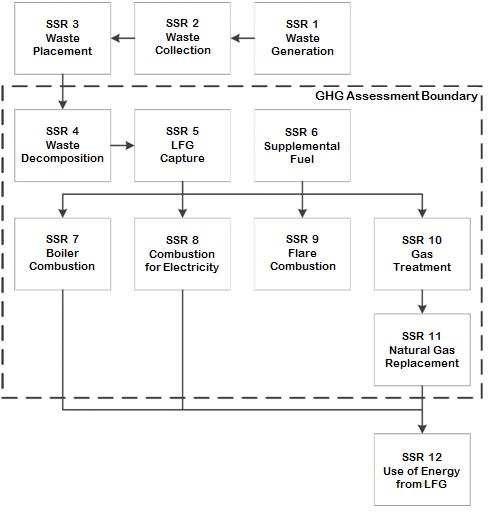
5. GHG Assessment Boundary
-
The following SSRs have been considered in determining the GHG Assessment Boundary.
- Figure 5.1 illustrates all relevant GHG SSRs associated with landfill activities and delineates the GHG Assessment Boundary.
- Table 5.1 provides greater detail on each relevant GHG SSR associated with landfill activities and includes justification for their inclusion or exclusion from the GHG Assessment Boundary.
Figure 5.1 Illustration of the GHG Assessment Boundary
| SSR | Source Description | Gas | Relevant to Baseline Scenario (B) or Initiative (I) | Included or Excluded | Justification/Explanation |
|---|---|---|---|---|---|
| 1 | Waste Generation | N/A | B, I | Excluded | GHG emissions from this source are assumed to be equal in the baseline scenario and initiative |
| 2 | Waste Collection | CO2, CH4, N2O | B, I | Excluded | GHG emissions from this source are assumed to be equal in the baseline scenario and initiative |
| 3 | Waste Placement | CO2, CH4, N2O | B, I | Excluded | GHG emissions from this source are assumed to be equal in the baseline scenario and initiative |
| 4 | Decomposition of Waste that has been landfilled | CO2 | B, I | Excluded | Biogenic CO2 emissions are excluded |
| 4 | Decomposition of Waste that has been landfilled | CH4 | B, I | Included | Primary source of GHG emissions in the baseline scenario. Calculated based on destruction in ineligible and eligible destruction devices |
| 5 | LFG Collection System | CO2 | B,I | Included | The CO2 emissions associated with the energy used for collection of LFG |
| 5 | LFG Collection System | CH4 | B,I | Excluded | Fugitive CH4 released prior to reaching the flow meter is assumed to have been released in the baseline scenario. CH4 emissions from energy are assumed to be very small |
| 5 | LFG Collection System | N2O | B,I | Excluded | This emission source is assumed to be very small |
| 6 | Supplemental Fuel | CO2 | B,I | Included | The initiative may use supplemental fossil fuel, to enhance the heat content of the LFG which results in non-biogenic GHG emissions |
| 6 | Supplemental Fuel | CH4 | B,I | Included | Calculated based on destruction efficiency of the eligible destruction device |
| 6 | Supplemental Fuel | N2O | B,I | Excluded | This emission source is assumed to be very small |
| 7 | LFG Destruction-Boiler | CO2 | B,I | Excluded | Biogenic CO2 emissions are excluded |
| 7 | LFG Destruction-Boiler | CH4 | B,I | Included | Calculated based on destruction efficiency of the ineligible or eligible device |
| 7 | LFG Destruction- Boiler | N2O | B,I | Excluded | This emission source is assumed to be very small |
| 8 | LFG Destruction- Combustion engine, turbine, micro turbine | CO2 | B,I | Excluded | Biogenic CO2 emissions are excluded |
| 8 | LFG Destruction- Combustion engine, turbine, micro turbine | CH4 | B,I | Included | Calculated based on destruction efficiency of the ineligible or eligible destruction device |
| 8 | LFG Destruction- Combustion engine, turbine, micro turbine | N2O | B,I | Excluded | This emission source is assumed to be very small |
| 9 | LFG Destruction– Flare | CO2 | B,I | Excluded | Biogenic CO2 emissions are excluded |
| 9 | LFG Destruction– Flare | CH4 | B,I | Included | Calculated based on destruction efficiency of the ineligible or eligible destruction device |
| 9 | LFG Destruction– Flare | N2O | B,I | Excluded | This emission source is assumed to be very small |
| 10 | LFG Treatment and Upgrade | CO2 | B,I | Included | Landfill initiatives may result in GHG emissions from additional energy used to treat and/or upgrade the CH4 concentration of the LFG |
| 10 | LFG Treatment and Upgrade | CH4 | B,I | Excluded | This emission source is assumed to be very small |
| 10 | LFG Treatment and Upgrade | N2O | B,I | Excluded | This emission source is assumed to be very small |
| 11 | LFG Destruction– Natural Gas Replacement End Use (direct use boiler, NG transmission pipeline, vehicle fuel, CH4 liquefaction) | CO2 | B,I | Excluded | Biogenic emissions are excluded |
| 11 | LFG Destruction– Natural Gas Replacement End Use (direct use boiler, NG transmission pipeline, vehicle fuel, CH4 liquefaction) | CH4 | B,I | Included | Calculated based on destruction efficiency of the ineligible or eligible destruction device |
| 11 | LFG Destruction– Natural Gas Replacement End Use (direct use boiler, NG transmission pipeline, vehicle fuel, CH4 liquefaction) | N2O | B,I | Excluded | Assumed to be very small |
| 12 | Use of Energy from LFG to Displace Fossil Energy | CO2 | B,I | Excluded | This protocol does not include crediting for displacement of GHG emissions from grid-connected electricity or fossil fuels |
6. Calculation of Emission Reductions
- Reductions of GHG emissions from the initiative during a reporting period shall be calculated in accordance with Equation 6.1.
-
GHG emission reductions shall not be calculated for any period during a reporting period in which:
- the device monitoring an eligible destruction device was not operating; or
- the eligible destruction device was not operating.
Equation 6.1 Calculating Initiative GHG Emission Reductions
ER = BE − PE
Where,
ER = GHG emission reductions from the initiative during the reporting period (tCO2e)
BE = Baseline scenario emissions during the reporting period, calculated using Equation 6.2 (tCO2e)
PE = Initiative emissions during the reporting period, calculated using Equation 6.11 (tCO2e)
6.1 Calculation of Baseline Scenario Emissions
- Baseline scenario emissions of the initiative for a reporting period shall be calculated in accordance with Equation 6.2.
Equation 6.2 Calculating Baseline Scenario Emissions
BE = (CH4DestPR) × GWPCH4 × (1 − OX) × (1 − DF) − Destbase × (1 − ox)
Where,
BE = Baseline scenario emissions during the reporting period (tCO2e)
CH4DestPR = Total quantity of CH4 destroyed by all eligible destruction devices during the reporting period, calculated in accordance with Equation 6.3 (tCH4)
GWPCH4 = Global Warming Potential for CH4, as set out in O. Reg. 143/16 (tCO2e/tCH4)
OX = Factor for the oxidation of CH4 by soil bacteria, determined in accordance with Section 7.2.7
DF = Discount factor is 0 or 0.1, determined in accordance with Section 7.2.3
Destbase = Adjustment to account for baseline scenario CH4 destruction calculated in accordance with Equation 6.6 (tCO2e)Equation 6.3 Total Landfill CH4 Destroyed
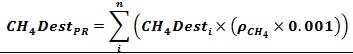
Where,
CH4DestPR = Total quantity of CH4 destroyed by all eligible destruction devices during the reporting period (tCH4)
n = Number of eligible destruction devices
i = Eligible destruction device
CH4Desti = Net quantity of CH4 destroyed by each eligible destruction device i during the reporting period, calculated in accordance with Equation 6.4 (m3 CH4)
ρCH4 = Density of CH4 at the reference temperature, as set out in Table A.2 (kg CH4/m3CH4)
0.001 = Conversion factor, kilograms to tonnes (tCH4/kgCH4)Equation 6.4 Net Landfill CH4 Emissions Destroyed by each Eligible Destruction Device
CH4Desti = Qi × DEi
Where,
CH4Desti = Net quantity of CH4 destroyed by eligible destruction device i during the reporting period (m3CH4)
Qi = Total quantity of CH4 sent to eligible destruction device i during the reporting period, calculated in accordance with Equation 6.5 (m3CH4)
i = Eligible destruction device
DEi = CH4 destruction efficiency of eligible destruction device i, as set out in Table A.1Equation 6.5 Total Quantity of CH4 Sent to Each Eligible Device
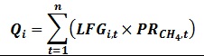
Where,
Qi = Total quantity of CH4 sent to eligible destruction device i during the reporting period (m3CH4)
n = Number of measurement periods
t = Measurement period as set out in Table 7.1
LFGi,t = Corrected volume of LFG sent to eligible destruction device “i” during measurement period “t”, determined in accordance with Section 7.2.2 (m3LFG)
PRCH4,t = Average ratio of CH4 to LFG in the LFG, for the measurement period “t” (m3CH4/m3LFG) - Equation 6.6 shall be used to determine the baseline adjustment amount where there was CH4 destruction before the state date of the initiative.
Equation 6.6 Baseline Adjustment for Destruction in the Baseline Scenario
Destbase = BDdiscount × ρCH4 × 0.001 × GWPCH4
Where,
Destbase = Adjustment to account for baseline scenario CH4 destruction (tCO2e)
BDdiscount = Amount of CH4 that would have been destroyed during the reporting period, in the baseline scenario without the initiative, calculated in accordance with Subsection 6.1(c) (m3 CH4)
ρCH$ = Density of CH4 at the reference temperature, as set out in Table A.2 (kgCH4/m3CH4)
0.001 = Conversion factor, kilograms to tonnes(tCH4/kgCH4)
GWPCH4 = Global Warming Potential for CH4, as set out in O. Reg. 143/16 (tCO2e/tCH4) -
BDdiscount shall be determined using either:
- BDdiscount that is equal to the measured quantity of CH4 that is recovered through an LFG collection system installed into the corresponding cell or waste mass where the LFG flow was calculated using Equation 6.3.
footnote 6 - BDdiscount that has been calculated per Equation 6.7 and monitored per Section 7.2.6.
Equation 6.7 Calculating Baseline Adjustment for Ineligible Devices
BDdiscount = LFGB × BCH4
Where,
BDdiscount = The amount of CH4 that would have been destroyed during the reporting period, in the baseline scenario. (m3 CH4)
LFGB = Amount of LFG that would have been destroyed by an ineligible destruction device during the reporting period, calculated in accordance with Equation 6.8 (m3LFG)
BCH4 = The average ratio of CH4 to LFG, in the LFG that would have been destroyed by an ineligible destruction device during the reporting period, calculated in accordance with Equation 6.9. (m3 CH4/m3 LFG)Equation 6.8 Calculating Baseline Discount for an Ineligible Device
LFGB = 525,600 × 90%UCL (LFGflowrate)
Where,
LFGB = LFG that would have been destroyed by an ineligible destruction device during the reporting period (m3 LFG)
90%UCL (LFGflowrate) = 90% upper confidence limit of the average flow rate in the metered period, calculated in accordance with Equation 6.10 (m3/min LFG)
525,600 = Minutes in one year (min/yr)Equation 6.9 Calculating the average ratio of CH4 to LFG for in Ineligible Device
BCH4 = 90%UCL (BCH4, t)
Where,
BCH4 = The average ratio of CH4 to LFG in the LFG, that would have been destroyed by an ineligible device during the reporting period (m3 CH4/m3 LFG)
90%UCL (BCH4,t) = 90% upper confidence limit of the average CH4 concentration in the metered period, calculated in accordance with Equation 6.10 (m3 CH4/m3 LFG)Equation 6.10 Calculating 90% Upper Confidence Limit
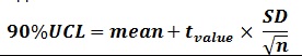
Where,
mean = Sample mean (of BCH4,t or LFGflowrate) (m3 or %)
tvalue = 90% t-value coefficient for data set with degrees of freedom df
SD = Standard deviation of the sample (of BCH4,t or LFGflowrate) (m3 or %)
n = Sample size
df = Degrees of freedom, n-1 - BDdiscount that is equal to the measured quantity of CH4 that is recovered through an LFG collection system installed into the corresponding cell or waste mass where the LFG flow was calculated using Equation 6.3.
Calculation of Initiative Emissions
- Initiative emissions are actual GHG emissions that occur within the GHG Assessment Boundary calculated in accordance with Equation 6.11.
Equation 6.11 Calculating Initiative Emissions from GHG Assessment Boundary
PE = FFCO2 + ELCO2 + NGemissions
Where,
PE = Initiative GHG emissions during reporting period (tCO2e)
FFCO2 = Total CO2 emissions from the use of fossil fuels during the reporting period, calculated in accordance with Equation 6.12 (tCO2e)
ELCO2 = Total CO2 emissions from the use of electricity during the reporting period, calculated in accordance with Equation 6.13 (tCO2e)
NGemissions = Total GHG emissions from the use of supplemental natural gas during the reporting period, calculated in accordance with Equation 6.14 (tCO2e)Equation 6.12 Calculating Initiative CO2 Emissions from Fossil Fuel Use
Where,
FFCO2 = Total CO2 emissions from the use of fossil fuels, other than supplemental natural gas, during the reporting period (tCO2e)
n = Number of types of fossil fuels
j = Type of fossil fuel
FFPR,j = Annual quantity of fossil fuel j consumed in the operation of equipment within the initiative boundary. (quantity of fossil fuel)
EFCF,j = CO2 emission factor for fossil fuel j, as set out in ON.20 of the QRV Guideline (kgCO2 ⁄ quantity of fossil fuel)
0.001 = Conversion factor, kilograms to tonnes (tCO2/kgCO2)Equation 6.13 Calculating Initiative CO2 Emissions from Electricity Use
ELCO2 = ELPR × ELEL × 0.001
Where,
ELCO2 = Total CO2 emissions from the use of electricity for the initiative during the reporting period (tCO2)
ELPR = Total electricity used for the initiative during the reporting period (MWh)
ELEL = CO2 emission factor for electricity generation from the province in which the initiative is located, as set out in the version of the NIR that is published immediately before the end of the reporting period (kg CO2/MWh)
0.001 = Conversion factor, kilograms to tonnes (tCO2/kgCO2)Equation 6.14 Calculating Initiative GHG Emissions from the Use of Supplemental Natural Gas

Where,
NGemissions = Total GHG emissions from the use of supplemental natural gas during the reporting period (tCO2e)
n = Number of eligible destruction devices
i = Eligible destruction device
NGi = Total quantity of supplemental natural gas sent to eligible destruction device i during the reporting period (m3NG)
NGCH4 = Average ratio of CH4 to NG in the supplemental natural gas, as set out in the supplier’s specifications (m3CH4/m3NG)
ρCH4 = Density of CH4 at the reference temperature, as set out in Table A.2 (kgCH4/m3CH4)
0.001 = Conversion factor, kilograms to tonnes (tCH4/kgsCH4)
DEi = CH4 destruction efficiency of eligible destruction device i, as set out in Table A.1
GWPCH4 = Global Warming Potential for CH4, as set out in O. Reg. 143/16 (tCO2e/tCH4)
12/16 = Molecular mass ratio, carbon to CH4 (C/CH4)
44/12 = Molecular mass ratio, CO2 to carbon (CO2/C)
7. Data Management and Monitoring
7.1 Data Collection
- A data management system shall be implemented to collect, manage and store information related to the initiative in a way that ensures the integrity, exhaustiveness, accuracy and validity of the information.
-
The data management system for the initiative shall include procedures to:
- Monitor the performance of the initiative and the operation of all initiative-related equipment, in accordance with Sections 7.2 ,7.3 and 7.5;
- Manage information, including data in respect of the baseline scenario and the initiative;
- Provide the accredited verification body access to the landfill site, suppliers and where applicable, the owner or operator of any offsite destruction devices and any other information or persons that the accredited verification body may require to verify the initiative.
- Assess whether the initiative meets the eligibility criteria set out in the Regulation and this protocol;
- Identify and record any violations of legal requirements that apply to the initiative and that may have an impact on the amount of GHG reductions, avoidances or removals; and
- Assess and record a description of the impact of each violation identified under paragraph 5.
-
The data management system for the initiative shall include records required by the Regulation and this protocol, including the following information:
-
All baseline scenario and initiative continuous monitoring devices shall record values every 15 minutes, except as set out in paragraph (1) below, and include the average at a minimum frequency of daily.
- Initiatives with continuous CH4 analyzers may record values at frequencies other than every 15 minutes in accordance with the data acquisition system, and include the average at a minimum frequency of daily.
- The value of Destbase shall be aggregated at a frequency of at least weekly, and the selected frequency shall be applied consistently throughout the reporting period.
- All other baseline scenario monitoring devices shall record one measured value per day on the day the measurement was made.
- All other monitoring devices shall record values and average those values at the frequencies set out in Section 7.
- Documentation of the engineering design and flow characteristics of the LFG collection system.
-
7.2 Monitoring Requirements
7.2.1 General
- Procedures shall be established and followed to accurately assess whether the initiative meets the applicable eligibility criteria set out in Section 4.
- All initiative-related equipment shall be operated in a manner consistent with the manufacturer’s specifications and in accordance with the Section 7 and the performance of the initiative shall be monitored in accordance with Section 7.
- Electricity data may be measured using an on-site meter or determined using electricity purchasing records.
- Fossil fuel use may be determined using monthly fossil fuel purchasing records.
7.2.2 Flow Meters
-
The LFG collection system shall be monitored with equipment that directly meters the flow of LFG delivered to each eligible and ineligible destruction device, measured continuously.
- A single meter may be used for multiple, identical destruction devices.
- The temperature and pressure of the LFG shall be measured separately and continuously.
-
All flow data collected shall be corrected to reference pressure and reference conditions as follows:
-
The correction shall be made using:
- The volume from the flow meter when the meter corrects for temperature and pressure; or
- Equation 7.1 to calculate the corrected volume, when the condition in i is not met.
- The reference pressure shall be 1 atm (101.325 kPa),
-
The reference temperature may be chosen from Table A.2, based on any applicable reference temperature standard of the jurisdiction in which the initiative is located.
- The reference temperature shall be applied consistently for data adjustment during the reporting period.
-
- The density of CH4 at the reference temperature that is set out in Table A.2.
Equation 7.1 Adjusting the LFG Flow for Temperature and Pressure
LFGi,t = LFGuncorrected × (Tref ⁄ Tm) × (Pm ⁄ 101.325)
Where,
LFGi,t = Corrected volume of LFG sent to eligible destruction device i, in time interval t (m3 LFG)
LFGuncorrected = Uncorrected volume of LFG collected for the given interval (m3 LFG)
Pm = Measured pressure of the LFG for the given time interval (kPa)
Tref = Reference temperature of the LFG for the initiative (K)
Tm = Measured temperature of LFG for the given time interval (K)
101.325 = Reference pressure of the LFG for the initiative (kPa)
7.2.3 CH4 Analyzers
-
The LFG collection system shall be monitored with equipment that directly calculates the % of CH4 in the LFG and the measurements on which this calculation is based are made using:
- A continuous CH4 analyzer (This is the preferred equipment).
-
Where a continuous CH4 analyzer is not used, a non-continuous CH4 measurement may be used if:
- measurement is obtained at a frequency of at least weekly;
- the uncertainty associated with these measurements is accounted for by applying a 10% discount factor to the total quantity of CH4 collected and destroyed in Equation 6.2; and,
-
The following device is used:
- a calibrated, portable CH4 analyzer; or
- a device that collects LFG samples at least weekly into a common container which is then analyzed at least monthly by an off-site laboratory that provides an average CH4 concentration of the sample.
7.2.4 Arrangement of Devices in the LFG Collection System
- The number and arrangement of flow meters shall be sufficient to track the LFG flow to each eligible and ineligible destruction device.
- The flow meter shall be placed such that it measures the volume of LFG delivered to each eligible and ineligible destruction device prior to the introduction of any supplemental fuels.
- The CH4 analyzer shall be placed such that it measures CH4 concentration of the LFG delivered to an eligible or ineligible destruction device prior to the introduction of any supplemental fuel.
- A moisture-removing component may separate the CH4 analyzer and the flow meter where the CH4 analyzer is placed before the moisture-removing component (wet basis), and the flow meter is placed after that component (dry basis).
- A moisture-removing component shall not separate the CH4 analyzer and flow meter in any other configuration other than as described in paragraph (d) above.
7.2.5 Operational Status of Eligible Destruction Devices
- Unless the eligible destruction device is not operating and the engineering design of the LFG collection system is such that LFG is not released when the eligible destruction device is not operating and that such design elements are functioning properly and there is documented evidence to support this, the operational status of the LFG collection system and each eligible destruction device shall be monitored with measurements recorded at least hourly.
- When a single flow meter is used for multiple, identical eligible destruction devices per Subsection 7.2.2(a)1, the operational status of each destruction device shall be monitored separately unless the design of the eligible destruction device is such that LFG is not released when it is not operating and there is documented evidence to support this.
- Where LFG is delivered from the landfill site to a destruction device at another facility via a direct use pipeline, reasonable efforts shall be made to obtain data demonstrating the type of destruction device used at the other facility and the operational status of that device.
- Where LFG is delivered from the landfill site to a destruction device via injection into a natural gas transmission pipeline, reasonable efforts shall be made to obtain data demonstrating the operational status of the natural gas transmission pipeline.
-
If it is not possible to obtain the dataset out in paragraphs (c) and (d), reasonable evidence must be obtained demonstrating that there has been no significant release of LFG between when it was collected and when it was destroyed and that the appropriate destruction efficiency value, set out in Table A.1, has been applied. Evidence may include:
- A signed attestation from the owner or operator of the pipeline that no significant release of LFG occurred during the reporting period;
- Supporting documents and records such as electrical output data, engineering designs and safety features that demonstrate LFG is not released when the destruction device is not operating or that the flow of LFG off-site can be shut off in the event of an emergency or any other supporting documents.
7.2.6 Baseline Scenario Monitoring Period
-
Monitoring of all ineligible destruction devices shall be done over a period of at least 3 consecutive months prior to the start date (“baseline scenario monitoring period”).
- The baseline scenario monitoring period cannot include a period where the volume of LFG flow that is measured is decreased by activities related to the start up or testing period the initiative (e.g., pressure changes from the installation of wells, etc.).
- CH4 destruction shall be monitored at a frequency of at least weekly during the baseline scenario monitoring period, and extrapolated to one year based on the 90% upper confidence limit of the CH4 destruction values recorded during this period. (Note: Monitoring for a period longer than three months, or at a frequency greater than weekly, may lessen statistical uncertainty and reduce the required BDdiscount.)
-
LFG flow shall be monitored at a frequency of at least weekly during the baseline scenario monitoring period, and shall be normalized to maximum flow capacity (m3/min).
- For any time interval in which the LFG flow is below the measurable range for the monitoring device, the minimum flow value of the monitoring device shall be applied to that time interval.
- CH4 concentration shall be monitored at a frequency of at least weekly during the baseline scenario monitoring period.
- When using Subsection 6.1(c)(1) to determine BDdiscount, the quantity of CH4 shall be measured for a minimum period of one month during the baseline scenario monitoring period.
7.2.7 Oxidation
- For the purposes of determining the oxidation amount, the fill area of the landfill with a geomembrane shall be determined at the beginning of each reporting period.
-
Oxidation of CH4 in the landfill shall be determined in the following manner:
- For a landfill site with a geomembrane where the entire fill area has a geomembrane, use a CH4 oxidation rate of zero (0%).
- For a landfill, without a geomembrane covering any fill area, use a CH4 oxidation rate of 0.1 (10 %).
- For a landfill that has some of the fill area with a geomembrane, the CH4 oxidation rate shall be a proportionate value determined in accordance with Equation 7.2.
Equation 7.2 Calculating the Oxidation of CH4 by Soil Bacteria
OX = [(0 × areac) + (0.1 × areau)] ⁄ (areac + areau)
Where,
OX = Factor for the oxidation of CH4 by soil bacteria
areac = Area covered by a geomembrane (m2)
area u = Area uncovered by a geomembrane (m2)
0 = CH4 oxidation rate of the area covered by a geomembrane, (zero, 0%)
0.1 = CH4 oxidation rate of the area uncovered by a geomembrane, (10%)
7.3 Instrument Quality Assurance and Quality Control (QA/QC)
-
LFG flow meters and CH4 analyzers shall be:
- Located and installed for the intended use, in accordance with manufacturer specifications;
- Calibrated at the time of installation;
- Cleaned and inspected in accordance with the manufacturer’s specifications;
-
Not later than 2 months before the end of a reporting period:
- Checked for accuracy by a qualified and independent person, either using a portable instrument, such as a pitot tube, or by following the manufacturer’s specifications, and the percentage drift recorded; or
- Calibrated by the manufacturer, or by a third party certified for that purpose by the manufacturer;
and;
- Calibrated by the manufacturer, or by a third-party certified for that purpose by the manufacturer, in accordance with the manufacturer’s specified frequency or every 5 years, whichever is more frequent.
- Flow meters and CH4 analyzers that are not portable devices but are installed temporarily shall be calibrated at the time of installation.
-
The LFG flow meter and CH4 analyzer calibration accuracy must show that these monitoring devices provide a reading of volumetric flow and CH4 concentration that is within a ± 5% accuracy threshold.
- When the device shows a shift outside the ± 5% accuracy threshold, appropriate corrective action(s) shall be taken, such as cleaning or adjusting the sensor in accordance with the manufacturer’s specification.
- The device shall be rechecked for measurement accuracy in accordance with Subsection 7.3(a)4.i after the corrective action.
- If the device is still out of the ± 5% accuracy threshold, the device shall be calibrated by the manufacturer or by a third party certified for that purpose by the manufacturer.
-
For the entire period from the last time the monitoring device showed a reading within the ± 5% accuracy threshold until such time as the monitoring device shows a return to the accuracy threshold all the data from the monitoring device shall be corrected according to the following procedure:
- When the inaccuracy of the device indicates an under-reporting of flow rate or CH4 concentration, the measured values taken by the inaccurate device, without correction shall be used;
- When the inaccuracy of the device indicates an over-reporting of flow rates or CH4 concentration, the measured values of the inaccurate device shall be corrected by the percentage that the device was out of the ± 5% accuracy threshold.
-
If a portable CH4 analyzer is used to check accuracy, it shall be:
- Maintained in accordance with the manufacturer’s specifications; and
- Calibrated by the manufacturer or by a third party certified for that purpose by the manufacturer for that purpose in accordance with the manufacturer’s specified frequency or annually, whichever is more frequent.
- Equipment used for monitoring parameters other than LFG flow and CH4 concentration (e.g., standalone temperature sensors, flare thermocouples, etc.) shall be installed, maintained and calibrated in accordance with the manufacturer’s specifications.
7.4 Missing Data
-
Missing data from a monitoring device may only be replaced using the methodology in Appendix B. The methodology in Appendix B may only be used if the following two conditions are met:
- The operational status of the eligible destruction device can be demonstrated in accordance with the requirements of Section 7.2.5; and
- The operational status and proper functioning of the device monitoring the eligible destruction device can be demonstrated in accordance with the requirements of Section 7.3.
-
If the methodology in Appendix B is being used to replace missing data from a flow meter or CH4 analyzer then data may only be replaced in accordance with the following rules:
- LFG flow rate may be replaced when CH4 concentration is not missing and where a continuous CH4 analyzer was used to measure CH4 concentration and the CH4 content was consistent with normal operations; or
- CH4 concentration may be replaced when flow meter data is not missing and a flow meter demonstrates that the LFG flow rate was consistent with normal operations; or
- Where both CH4 concentration and LFG flow rate are missing, data may only be replaced for electric generators and natural gas injection and only in accordance with(c) and (d) below.
- For initiatives that destroy LFG in an eligible destruction device that also generates electricity, the missing data may be replaced for periods of up to 6 months after the applicable version of the protocol comes into effect by using Equation B.1, in Appendix B if the electrical output for the period of missing data has been monitored.
-
For initiatives that inject LFG into a natural gas transmission pipeline, the missing data for periods up to 6 months after the applicable version of the protocol came into effect may be replaced through either:
- the use of the volumetric CH4 data as reported by the flow meter at the point of pipeline injection, or,
-
by using Equation B.2 in Appendix B if the data is reported in units of energy, but only if:
- The volume of LFG is continuously monitored throughout the period of the data gap;
- Any supplemental natural gas mixed with the LFG prior to the custody transfer meter is monitored throughout the period of the data gap and subtracted from the volume in i; and
- Any other fuel sent to the pipeline, is directly monitored throughout the period of the data gap and subtracted from the volume in i.
7.5 Monitoring Parameters
- Table 7.1 sets out the monitoring parameters required to be used in the calculation of baseline scenario and initiative emissions
| Eq. # | Parameter | Description in Equation | Units | Calculated (c), Measured (m), Reference (r), Operating Records (o) | Measurement Frequency | References |
|---|---|---|---|---|---|---|
| N/A | Operating status of destruction device | Unit determined per destruction device | m | Hourly | ||
| Equation 6.2 | CH4DestPR | Total quantity of CH4 destroyed by all eligible destruction devices during the reporting period | tCH4 | c | Once per reporting period | Calculated in accordance with Equation 6.3 |
| Equation 6.2, Equation 6.6, Equation 6.14 | GWPCH4 | Global Warming Potential for CH4 | tCO2e/tCH4 | r | Once per reporting period | As set out in O. Reg. 143/16 |
| Equation 6.2 | OX | Factor for the oxidation of CH4 by soil bacteria | N/A | r | Once per reporting period | Determined in accordance with Section 7.2.7 |
| Equation 6.2 | DF | Discount factor is 0 or 0.1 | N/A | r | Once per reporting period | Determined in accordance with Section 7.2.3 |
| Equation 6.2 | Destbase | Adjustment to account for baseline CH4 destruction | tCO2e | c | At least weekly | Calculated in accordance with Equation 6.6 |
| Equation 6.3, Equation 6.14 | n | Number of eligible destruction devices | N/A | r | ||
| Equation 6.3, Equation 6.4, Equation 6.14 | i | Eligible destruction device | N/A | r | ||
| Equation 6.3 | CH4Desti | Net quantity of CH4 destroyed by each eligible destruction device i during the reporting period | m3 CH4 | c | Calculated in accordance with Equation 6.4 | |
| Equation 6.3, Equation 6.6, Equation 6.14 | ρCH4 | Density of CH4 at the reference temperature | kgCH4/m3CH4 | r | Once per reporting period | As set out in Table A.2 |
| Equation 6.4, Equation 6.5 | Qi | Total quantity of CH4 sent to eligible destruction device i during the reporting period | m3 CH4 | c | Daily (if CH4 is monitored continuously); Weekly (if CH4 is monitored weekly) | Calculated in accordance with Equation 6.5 |
| Equation 6.4, Equation 6.14, Equation B.1, Equation B.2 | DEi | CH4 destruction efficiency of eligible destruction device i | N/A | r/m | Once per reporting period | As set out in Table A.1 |
| Equation 6.5 | n | Number of measurement periods | N/A | r | ||
| Equation 6.5, Equation B.2 | t | Measurement period | m | Continuously, daily, or weekly | ||
| Equation 6.5 | LFGi,t | Corrected volume of LFG sent to eligible destruction device i during measurement period t | m3 LFG | m/c | Continuously | Measured for cases where the meter internally corrects to standard conditions, otherwise calculated in accordance with Equation 7.1 |
| Equation 6.5 | PRCH4,t | Average ratio of CH4 to LFG in the LFG, for measurement period t | m3CH4/m3LFG | m | Continuously or weekly | |
| Equation 6.6, Equation 6.7 | BDdiscount | Amount of CH4 that would have been destroyed during the reporting period, in the baseline without the initiative | m3 CH4 | c | Once per reporting period | Calculated in accordance with Subsection 6.1 (c) |
| Equation 6.7 | LFGB | LFG that would have been destroyed by an ineligible destruction device during the reporting period | m3 LFG | c | Once per reporting period | Calculated in accordance with Equation 6.8 |
| Equation 6.7 | BCH4 | The average ratio of CH4 to LFG in the LFG that would have been destroyed by an ineligible devices during the reporting period | m3CH4/m3LFG | m | Continuously or weekly | Calculated in accordance with Equation 6.9 |
| Equation 6.8 | 90%UCL(LFGflowrate) | 90% upper confidence limit of the average flow rate in the metered period | m3/minLFG | c | Once per reporting period | Calculated in accordance with Equation 6.10 |
| Equation 6.9 | 90%UCL(BCH4,t) | 90% upper confidence limit of the average CH4 concentration in the metered period | m3/min LFG | c | Once per reporting period | Calculated in accordance with Equation 6.10 |
| Equation 6.10 | tvalue | The 90% t-value coefficient for data set with degrees of freedom | N/A | c | Once per reporting period | |
| Equation 6.10 | SD | Standard deviation of the sample | m3 or % | c | Once per reporting period | |
| Equation 6.10 | n | Sample size | N/A | r | Once per reporting period | |
| Equation 6.10 | df | Degrees of freedom, n−1 | N/A | c | Once per reporting period | |
| Equation 6.11 | FFCO2 | Total CO2 emissions from the use of fossil fuels during the reporting period | tCO2e | c | Once per reporting period | Calculated in accordance with Equation 6.12 |
| Equation 6.11 | ELCO2 | Total CO2 emissions from the use of electricity during the reporting period | tCO2e | c | Once per reporting period | Calculated in accordance with Equation 6.13 |
| Equation 6.11 | NGemissions | Total GHG emissions from the use of supplemental natural gas during the reporting period | tCO2e | c | Once per reporting period | Calculated in accordance with Equation 6.14 |
| Equation 6.12 | n | Number of types of fossil fuel | N/A | o | Once per reporting period | |
| Equation 6.12 | j | Type of fossil fuel | N/A | o | Once per reporting period | |
| Equation 6.12 | FFPR,j | Annual quantity of fossil fuel j consumed in the operation of equipment within the GHG assessment boundary | kg (solid) m3 at standard conditions (gas) L (liquid) |
o | Once per reporting period | |
| Equation 6.12 | EFCF,j | CO2 emission factor for fossil fuel j | kg CO2/ quantity of fossil fuel | r | Once per reporting period | As set out in ON.20 of the QRV Guideline |
| Equation 6.13 | ELPR | Total electricity used during the reporting period | MWh | r | ||
| Equation 6.13 | ELEL | CO2 emission factor for electricity generation from the province in which the initiative is located | kgCO2/MWh | r | Once per reporting period | As set out in the NIR |
| Equation 6.14 | NGi | Total quantity of supplemental natural gas sent to eligible destruction device i during the reporting period | m3 NG | m/r | Continuously | |
| Equation 6.14, Equation B.1, Equation B.2 | NGCH4 | Average ratio of CH4 to NG in the supplemental natural gas | m3CH4/m3NG | m/r | Once per reporting period | |
| Equation 7.1 | LFGuncorrected | Uncorrected volume of LFG collected for the given interval | m3 LFG | m | Continuously | |
| Equation 7.1 | ρm | Measured pressure of the LFG for the given time interval | kPa | m | Continuously | |
| Equation 7.1 | Tref | Reference temperature of the LFG for the initiative | K | m | Once per reporting period | |
| Equation 7.1 | Tm | Measured temperature of LFG for the given time interval | K | m | Continuously | |
| Equation B.1 | EOi | Total electric output of device i during the period of missing data | kWh | m | Per data gap | |
| Equation B.1 | HRi | Heat rate of destruction device i | GJ/kWh | r | N/A | |
| Equation B.1, Equation B.2 | HHVCH4 | Higher heating value of the CH4 portion of LFG, 0.0359 | GJ/m3 | r | N/A | |
| Equation B.1, Equation B.2 | NGi | Total quantity of supplemental natural gas sent to device i during the period of the missing data | m3 NG | m/r | Continuously | |
| Equation B.2 | FEt | Fuel energy delivered during measurement period t | GJ | m | Per data gap |
8. Reversals
8.1 Reversals Listed for the Purposes of s. 20(1) paragraph 1
- There are no reversals listed in this protocol for the purpose of s. 20(1) paragraph 1.
8.2 Errors, Omissions or Misstatements
-
In the event that an error, omission or misstatement is discovered after Ontario offset credits have been created and issued for a reporting period, the Sponsor shall determine the total amount of the reversal by:
- Using this protocol to re-calculate the corrected value of the GHG emission reductions from the initiative during the reporting period for each initiative report affected by the reversal.
- Calculating the total reversal of GHG emission reductions from the initiative using Equation 8.1.
Equation 8.1 Calculating GHG Emission Reductions Reversed
Where
RE = GHG emission reductions reversed (tCO2e)
n = Total number of initiative reports affected by the reversal
r = Initiative reports affected by the reversal
ERc = Corrected GHG emission reductions from the initiative during the reporting period calculated in accordance with Subsection 8.2(a)(1) (tCO2e)
ERi = Initially reported GHG emission reductions from the initiative during the reporting period (tCO2e)
9. Reporting
- The following information shall be set out in an initiative report or a reversal report in addition to the information required by the Regulation.
9.1 Initiative Report
9.1.1 Eligibility Criteria Information
- The total waste capacity of the landfill
- Amount of waste in place
- For an operational landfill, the amount of waste accepted annually, in tonnes
- For a closed landfill, the amount of waste that was accepted annually in tonnes
- If a geomembrane has been used at the site, a description of whether the geomembrane, meets the requirements of Ontario Regulation 232/98 (Landfilling Sites).
9.1.2 Monitoring Information
- A description of the baseline scenario and how it was monitored in accordance with Section 7.2.6.
- Identify all eligible and ineligible destruction devices within the initiative GHG Assessment Boundary as set out in Section 5.
-
A description of how the initiative was monitored, including the following:
- A statement of whether the monitoring performed meets the requirements set out in Section 7.
- A statement of whether all gas flow meters and CH4 analyzers adhered to the instrument QA/QC requirements set out in Section 7.3.
- Where applicable, an identification of any deviations from the requirements set out in Section 7 and a description of whether these deviations should be considered material.
- Calibration certificates or verification reports on the calibration accuracy, from either the manufacturer or a qualified third-party certified by the manufacturer for each piece of monitoring equipment.
- Where applicable, identification of instances where any piece of equipment failed a calibration and a description of how the data from that equipment was corrected in accordance with Section 7.3, including any calculations used.
- Where applicable, identification of instances where the data substitution methodology set out in Section 7.4 was applied, and a description as to how the data was substituted including any calculations used.
- Identification of the measurement frequency used for each monitoring parameter, where multiple frequencies may be used in accordance with Section 7.5.
9.1.3 Quantification Information
- All calculations set out in Section 6, including any supporting calculations set out in Section 7, that were used.
- The reference temperature and density used.
- Identification of any source test data, if used in place of the default destruction efficiencies, as set out in Appendix A.
9.2 Reversal Report
9.2.1 General
- Information about the circumstances and causes of the reversal including the number of reporting periods affected.
- For each initiative report that was affected by the reversal, all information that has changed as a result of the reversal and a description of those changes.
- In the case of an error, omission or misstatement reversal, a description of the corrective actions taken to address the circumstances and causes of the reversal.
- Supporting documentation for each of the items in paragraphs (a) through (c) above.
9.2.2 Quantification Information
- All calculations set out in Section 8, including supporting calculations set out in Section 6 and Section 7, that were used to determine the amount of the reversal.
- Supporting documentation related to the calculations.
10. Record Keeping
-
The following records and documents shall be kept in addition to the records that are required to be kept under the Regulation:
- The information and data required under the monitoring requirements in Section 7, including all GHG calculations and related data inputs.
- Information on each eligible and if applicable ineligible flow meter, CH4 analyzer and destruction device used, including type, model number, serial number and manufacturer’s maintenance and calibration procedures.
-
Maintenance documents and records relating to collection, destruction and monitoring systems including:
- For each LFG flow meter and CH4 analyzers, records and documents relating to all instrument QA/QC activities.
- For a portable analyzer, time and place where measurements are taken and, for each measurement, the CH4 concentration in the LFG.
-
The calibration date, time and results for CH4 analyzers and flow meters, and the corrective measures applied if a piece of equipment failed to meet the requirements of this protocol:
- Flow meter calibrations shall be documented to show that the meter was calibrated to a range of flow rates corresponding to the flow rates expected at the landfill site.
- CH4 analyzer calibrations shall be documented to show that the calibration was carried out to a range of temperature and pressure conditions corresponding to the range of conditions measured at the landfill site.
- Records showing the quantity of waste disposed of at the landfill.
- All documentation related to any violations of legal requirements that apply to the initiative or that may have an impact on the amount of GHG reductions, avoidances or removals.
Appendix A: Parameters for Quantification
A.1 CH4 Destruction Efficiency
The appropriate CH4 destruction efficiency shall be selected from Table A.1 below.
| Eligible Destruction Device | Efficiency |
|---|---|
| Open Flare | 0.96 |
| Enclosed Flare | 0.995 |
| Internal Combustion Engine | 0.936 |
| Boiler | 0.98 |
| Microturbine or Large Gas Turbine | 0.995 |
| Boiler Following Upgrade and Injection into a Pipeline | 0.96 |
| CH4 Liquefaction Unit | 0.95 |
| Injection into Natural Gas Transmission Pipeline | 0.98 |
| Direct Use Pipeline (End Use Other than Boiler) | Per the appropriate end use device |
A.2 CH4 Density
- The appropriate CH4 density at the reference temperature shall be selected from Table A.2 below.
| Reference Pressure (kPa) | Reference Pressure (atm) | Reference Temperature (°C) | Reference Temperature (K) | Density of CH4(kg/m3) |
|---|---|---|---|---|
| 101.325 | 1 | 0 | 273.15 | 0.717 |
| 101.325 | 1 | 5 | 278.15 | 0.704 |
| 101.325 | 1 | 10 | 283.15 | 0.692 |
| 101.325 | 1 | 15 | 288.15 | 0.680 |
| 101.325 | 1 | 20 | 293.15 | 0.668 |
| 101.325 | 1 | 25 | 298.15 | 0.657 |
Appendix B: Missing Data Methods
B.1 Substitution Methods
- The appropriate substitution method to replace data shall be selected from Table B.1 below.
| Missing Data Period | Substitution Method |
|---|---|
| Less than 6 hours | Use the average of the 4 hours immediately before and following the missing data period |
| 6 to less than 24 hours | Use the 90% upper or lower confidence limit of the 72 hours prior to and after the missing data period, whichever results in greater conservativeness |
| 1 to 7 days | Use the 95% upper or lower confidence limit of the 72 hours prior to and after the missing data period, whichever results in greater conservativeness |
| More than 7 days | No data may be replaced and no reduction may be credited, except for initiatives that destroy LFG in a device that generates electricity or via pipeline injection, as set out in Subsections 7.4(c) and (d) respectively. |
B.2 Calculations
Equation B.1 Calculating Estimated Volume of CH4 Destroyed in Electricity Generators
CH4,dest,i,alt = {[(EOi × HRi) ⁄ HHVCH4] − NGi × NGCH4} × DEi
Where,
CH4,dest,i,alt = Net quantity of CH4 destroyed by electricity generating device i during the period of missing data (m3CH4)
EOi = Total electrical output of device i during the period of missing data (kWh)
HRi = Heat rate of destruction device i, as determined through the most recent source testing event. If no source test data are available, the highest heat rate specified by the manufacturer shall be used (GJ/kWh)
HHVCH4 = Higher heating value of the CH4 portion of the LFG, 0.0359 (GJ/m3CH4)
NGi = Total quantity of supplemental natural gas sent to device i during the period of the missing data (m3NG)
NGCH4 = Average ratio of CH4 to NG in the supplemental natural gas, as set out in the supplier’s specifications (m3CH4/m3NG)
DEi = CH4 destruction efficiency of device i, as set out in Table A.1 (%)
Equation B.2 Calculating Estimated Volume of CH4 Destroyed by Pipeline Injection
Where,
CH4,dest,i,alt = Total quantity of CH4 destroyed by pipeline injection device i during the period of missing data (m3CH4)
t = Measurement period
FEt = Fuel energy delivered during measurement period t, as reported in gas delivery data. (GJ)
HHVCH4 = Higher heating value of the CH4 portion of the LFG, 0.0359 (GJ/m3CH4)
NGi = Total quantity of supplemental natural gas sent to device i during the period of missing data (m3NG)
NGCH4 = Average ratio of CH4 to NG in the supplemental natural gas, according to the supplier’s specifications (m3CH4/m3NG)
0.98 = CH4 destruction efficiency of pipeline injection, as set out in Table A.1 (%)
Ozone Depleting Substances Initiative Protocol
Destruction of Ozone Depleting Substances Used as Foam Blowing Agents and Refrigerants
Protocol Version 1
Dated April 12, 2018
Abbreviations and Acronyms
- AHRI
- Air-Conditioning, Heating and Refrigeration Institute
- CFC
- Chlorofluorocarbons
- HCFC
- Hydrochlorofluorocarbons
- HFC
- Hydrofluorocarbons
1. Introduction
This protocol sets out the requirements that will enable a sponsor to undertake an ozone depleting substances (ODS) greenhouse gas (GHG) reduction initiative for the purpose of registering and receiving offset credits in Ontario’s cap and trade program.
The following sections outline the definition of an ODS GHG reduction initiative, the specific eligibility criteria, baseline scenario and initiative calculation methods, monitoring, data management and reporting requirements that apply to ODS GHG reduction initiatives.
2. Definitions
2.1 Terms
- Accredited Laboratory
- means a laboratory that is:
- Independent of the Sponsor and of the Qualified Destruction Facility; and
- Accredited for analysis of ODS by the Air-Conditioning, Heating and Refrigeration Institute in accordance with AHRI Standard 700 with Addendum 1 (2017 Standard for Specifications for Refrigerants) of that organization as amended from time.
- Aggregation
- means grouping together multiple containers of eligible ODS.
- Certificate of Destruction
- means a document that complies with the requirements set out in Section 7.7.2 of this Protocol provided by the Qualified Destruction Facility certifying the date, quantity, and type of eligible ODS destroyed at the Qualified Destruction Facility.
- Commercial refrigeration equipment
- means the refrigeration appliances, equipment or systems used in the retail food, cold storage warehouse or any other sector that requires cold storage.
- Container
- means an air and water-tight unit for storing or transporting eligible ODS contained in foam or used as or intended for use as a refrigerant without leakage or escape of ODS.
- Destruction
- means destruction that complies with the requirements in Section 7 of this Protocol of eligible ODS contained in foam or used or intended for use as a refrigerant by a Qualified Destruction Facility.
- Emission rate
- means the rate at which eligible ODS contained in foam or used or intended for use as a refrigerant is emitted and includes emissions from leaks during operation and servicing events.
- GHG assessment boundary
- means all the GHG sources, sinks and reservoirs (SSRs) that are required to be assessed because they are identified as included in Table 5.1 of this Protocol.
- Ozone Depleting Substances (ODS)
- means substances known to deplete the stratospheric ozone layer.
- Eligible ODS
- means an ozone depleting substance set out in Section 4.3 of this Protocol.
- Point of Origin
- means the locations as determined in accordance with Section 7.3 of this Protocol.
- Pure ODS
- means eligible ODS with a chemical composition of a minimum of 90% of a single chemical by mass, excluding moisture and high boiling residue and contained in a single container.
- Qualified Destruction Facility (QDF)
- means a facility that destroys, transforms or converts eligible ODS contained in foam or used as or intended for use as a refrigerant and complies with the requirements in Section 7.7 of this Protocol.
- Recharge
- means replenishment of refrigerants into an appliance, piece of equipment or system that is below full capacity.
- Reclaimed ODS
- means recovered eligible ODS that has been reprocessed and upgraded through processes such as filtering, drying, distillation or chemical treatment in order to restore the eligible ODS to a specified standard of performance.
- Recovery
- means the removal of eligible ODS from refrigeration, freezer or air-conditioning appliances, equipment and systems and deposited into a container intended for destruction.
- Substitute refrigerant
- means refrigerants that replace recovered eligible ODS.
- Substitute refrigerant emissions
- means greenhouse gas emissions from the use of substitute refrigerants.
2.2 References
- A reference to equipment in this Protocol includes containment vessels.
- A reference to eligible ODS used as a refrigerant in this Protocol includes eligible ODS intended for use as a refrigerant.
3. ODS GHG Reduction Initiative
3.1 Initiative Definition
- The ODS GHG reduction initiative (‘ODS Initiative’) is defined as an initiative that has activities specified in paragraphs 1. or 2. that are associated with the destruction of eligible ODS as set out in Section 4.4 of this Protocol .
- Activities for Eligible ODS Contained in Foam: Activities for ODS Initiatives for eligible ODS contained in foam include the collection, recovery, extraction, concentration, storage, transportation, mixing (where applicable), sampling, analysis, and destruction of the eligible ODS (‘ODS Foam Initiative’).
- Activities for Eligible ODS Used as or Intended for use as a Refrigerant: Activities for ODS Initiatives for eligible ODS used as or intended for use as a refrigerant include the collection, recovery, handling, transportation, mixing (where applicable), sampling, analysis, and destruction of the eligible ODS (‘ODS Refrigerant Initiative’).
- Activities listed above in paragraphs a)1. and a)2. that occur prior to the collection of eligible ODS at the Point of Origin are not part of the ODS Initiative.
- A single ODS Initiative may combine collection, recovery and destruction of eligible ODS contained in foam or used or intended for use as a refrigerant.
- All eligible ODS included in an ODS Initiative must be destroyed at a Qualified Destruction Facility.
3.2 Initiative Start Date
- The ODS Initiative start date is the date on which the destruction of eligible ODS commences as documented on a Certificate of Destruction.
4. Eligibility
4.1 General Requirements
- A legal requirement to destroy eligible ODS contained in foam or used as a refrigerant must not be applicable.
- An ODS Initiative must destroy eligible ODS that, in the absence of the ODS Initiative, would have been emitted to the atmosphere.
4.2 Duration of Initiative
- The duration for the ODS Initiative is:
- One year from the start date of the ODS Initiative; or
- Up to a maximum of 5 years from the start date of the ODS Initiative if all of the following conditions are met in each year following the first reporting period for the ODS Initiative:
- The extraction and destruction locations for the eligible ODS is the same as in the first reporting period of the ODS Initiative;
- The methods of destruction of eligible ODS are the same as in the first reporting period of the ODS Initiative;
- The types of appliances, equipment and systems from which eligible ODS are recovered are the same as in the first reporting period of the ODS Initiative;
- At least one destruction event for eligible ODS included in the ODS Initiative occurs; and
- An initiative report is prepared and verified in accordance with Sections 21 – 24 of the Regulation.
4.3 Eligible ODS
- The following ODS are eligible for the purposes of this Protocol:
- ODS Contained in Foam: The following ODS blowing agents contained in foam removed from refrigeration, freezer or air-conditioning equipment, systems or appliances at industrial, commercial, institutional or residential locations:
- CFC-11;
- CFC-12;
- HCFC-22; and
- HCFC-141b.
- ODS Used as a Refrigerant: The following ODS used as a refrigerant and removed from or intended for use in refrigeration, freezer or air-conditioning equipment, systems or appliances at industrial, commercial, institutional or residential locations:
- CFC-11;
- CFC-12;
- CFC-13;
- CFC-113;
- CFC-114; and
- CFC-115.
- ODS Contained in Foam: The following ODS blowing agents contained in foam removed from refrigeration, freezer or air-conditioning equipment, systems or appliances at industrial, commercial, institutional or residential locations:
- ODS that were used as or produced for use as solvents, medical aerosols or other applications are not eligible under this Protocol.
- Where an eligible ODS used as a refrigerant is removed from a refrigeration, freezer or air conditioning appliance, equipment or system that also contains eligible ODS contained in foam, and the destruction of the eligible ODS used as a refrigerant commences after October 22, 2016, the eligible ODS contained in foam must also be extracted and destroyed.
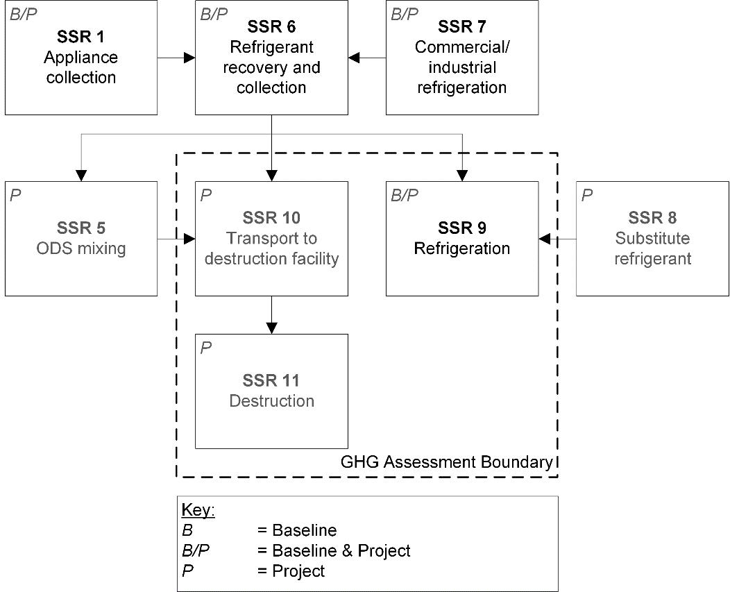
5. GHG Assessment Boundary
- The following SSRs have been considered in determining the GHG Assessment Boundary;
- Figure 5.1 and Figure 5.2 illustrate all relevant SSRs associated with the ODS Initiative and delineates the GHG Assessment Boundary.
- Table 5.1 provides greater detail on each relevant SSR associated with the ODS Initiative and identifies the inclusion or exclusion of the relevant SSR from the GHG Assessment Boundary.
Figure 5.1. GHG Assessment Boundary for eligible ODS Contained in Foam
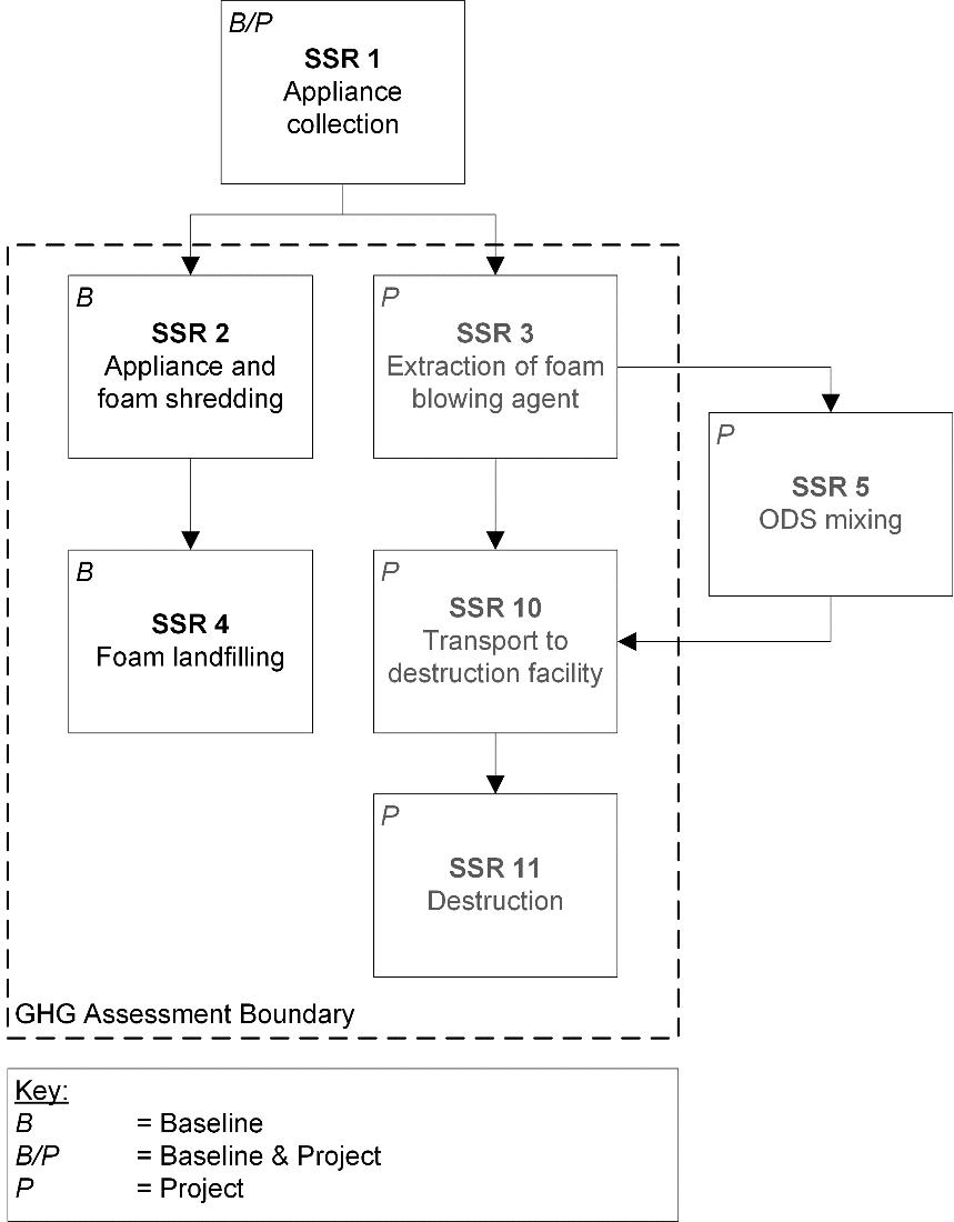
Figure 5.2. GHG Assessment Boundary for eligible ODS Used as a Refrigerant
| SSR # | SSR | Source Description | Type of Emission | Relevant to Baseline Scenario (B) and/or Initiative (I) | Included or Excluded |
|---|---|---|---|---|---|
| 1 | Appliance, Equipment and System Collection | Emissions from the collection and transportation to the Point of Origin of appliances, equipment and systems | CO2 | B, I | Excluded |
| 1 | Appliance, Equipment and System Collection | Emissions from the collection and transportation to the Point of Origin of appliances, equipment and systems | CH4 | B, I | Excluded |
| 1 | Appliance, Equipment and System Collection | Emissions from the collection and transportation to the Point of Origin of appliances, equipment and systems | N2O | B, I | Excluded |
| 2 | Appliance, Equipment and System Shredding | Emissions of eligible ODS from the shredding of appliances, equipment and systems for materials recovery | ODS | B | Included |
| 3 | Extraction of ODS contained in foam | Emissions of eligible ODS from the removal of foam ODS blowing agent from appliances, equipment and systems | ODS | I | Included |
| 4 | Disposal of foam at a landfill site | Emissions of eligible ODS from the disposal of foam at a landfill site | ODS | B | Included |
| 4 | Disposal of foam at a landfill site | Emissions of ODS degradation products from foam disposed of at a landfill site | HFC, HCFC | B | Excluded |
| 4 | Disposal of foam at a landfill site | Fossil fuel emissions from the transportation of shredded foam to a landfill site and from disposal at a landfill site | CO2 | B | Excluded |
| 4 | Disposal of foam at a landfill site | Fossil fuel emissions from the transportation of shredded foam to a landfill site and from disposal at a landfill site | CH4 | B | Excluded |
| 4 | Disposal of foam at a landfill site | Fossil fuel emissions from the transportation of shredded foam to a landfill site and from disposal at a landfill site | N2O | B | Excluded |
| 5 | ODS mixing | Fossil fuel emissions from eligible ODS mixing activities at mixing facility | CO2 | I | Excluded |
| 5 | ODS mixing | Fossil fuel emissions from eligible ODS mixing activities at mixing facility | CH4 | I | Excluded |
| 5 | ODS mixing | Fossil fuel emissions from eligible ODS mixing activities at mixing facility | N2O | I | Excluded |
| 6 | Refrigerant recovery and collection | Emissions of eligible ODS from the removal of refrigerant from appliances, equipment and systems | ODS | B, I | Excluded |
| 7 | Industrial and commercial refrigeration | Emissions of eligible ODS from appliances, equipment and systems leakage and maintenance | ODS | B, I | Excluded |
| 7 | Industrial and commercial refrigeration | Fossil fuel emissions attributable to the operation of refrigeration and air conditioning appliances, equipment and systems | CO2 | B, I | Excluded |
| 7 | Industrial and commercial refrigeration | Fossil fuel emissions attributable to the operation of refrigeration and air conditioning appliances, equipment and systems | CH4 | B, I | Excluded |
| 7 | Industrial and commercial refrigeration | Fossil fuel emissions attributable to the operation of refrigeration and air conditioning appliances, equipment and systems | N2O | B, I | Excluded |
| 8 | Production of substitute refrigerants | Emissions of substitute refrigerants during the production of substitute refrigerants | CO2e | I | Excluded |
| 8 | Production of substitute refrigerants | Fossil fuel emissions during the production of substitute refrigerants | CO2 | I | Excluded |
| 8 | Production of substitute refrigerants | Fossil fuel emissions during the production of substitute refrigerants | CH4 | I | Excluded |
| 8 | Production of substitute refrigerants | Fossil fuel emissions during the production of substitute refrigerants | N2O | I | Excluded |
| 9 | Refrigerants | Emissions of eligible ODS from leakage and maintenance during the continuous operation of appliances, equipment and systems | ODS | B | Included |
| 9 | Refrigerants | Emissions of substitute refrigerants from leakage and maintenance during the continuous operation of appliances, equipment and systems | CO2e | I | Included |
| 9 | Refrigerants | Indirect emissions from the use of electricity | CO2 | B, I | Excluded |
| 9 | Refrigerants | Indirect emissions from the use of electricity | CH4 | B, I | Excluded |
| 9 | Refrigerants | Indirect emissions from the use of electricity | N2O | B, I | Excluded |
| 10 | Transportation to the Qualified Destruction Facility | Emissions of fossil fuels from the transportation of eligible ODS from the Point of Origin to the Qualified Destruction Facility | CO2 | I | Included |
| 11 | Destruction of Eligible ODS | Emissions of eligible ODS from incomplete destruction at the Qualified Destruction Facility | ODS | I | Included |
| 11 | Destruction of Eligible ODS | Emissions from the oxidation of carbon contained in the destroyed eligible ODS | CO2e | I | Included |
| 11 | Destruction of Eligible ODS | Fossil fuel emissions from the destruction of eligible ODS in a destruction facility | CO2 | I | Included |
| 11 | Destruction of Eligible ODS | Fossil fuel emissions from the destruction of eligible ODS in a destruction facility | CH4 | I | Excluded |
| 11 | Destruction of Eligible ODS | Fossil fuel emissions from the destruction of eligible ODS in a destruction facility | N2O | I | Excluded |
| 11 | Destruction of Eligible ODS | Indirect emissions from the use of electricity | CO2 | I | Included |
| 11 | Destruction of Eligible ODS | Indirect emissions from the use of electricity | CH4 | I | Excluded |
| 11 | Destruction of Eligible ODS | Indirect emissions from the use of electricity | N2O | I | Excluded |
6. Calculation of Emission Reductions
-
Reductions of GHG emissions from the ODS Initiative for the reporting period shall be calculated in accordance with Equation 6.1.
Equaltion 6.1. Calculating Total ODS Initiative GHG Emission Reductions
ERt = BEt − PEt
Where,
ERt = Total GHG emission reductions from the ODS Initiative for the reporting period (tCO2e)
BEt = Total baseline scenario emissions for the reporting period, calculated using Equation 6.2 (tCO2e)
PEt = Total ODS Initiative emissions for the reporting period, calculated using Equation 6.6 (tCO2e)
6.1 Calculation of Baseline Scenario Emissions
- The total baseline scenario emissions shall be calculated using Equation 6.2.
Equation 6.2. Total Baseline Scenario Emissions
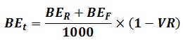
Where,
BEt = Total baseline scenario emissions for the reporting period (tCO2e)
BER = Baseline scenario emissions from the destruction of eligible ODS used as a refrigerant for the reporting period, calculated using Equation 6.4 (kgCO2e)
BEF = Baseline scenario emissions from the destruction of eligible ODS contained in foam for the reporting period, calculated using Equation 6.3 (kgCO2e)
1000 = Conversion from kilograms to tonnes (kgCO2e/tCO2e)
VR = Deduction for vapour composition risk determined in accordance with Subsection 6.1.1 (%)
Equation 6.3. Baseline Scenario Emissions for Eligible ODS Contained in Foam
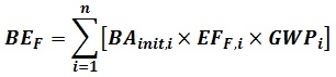
Where,
BEF = Baseline scenario emissions from to the destruction of eligible ODS contained in foam for the reporting period (kg CO2e)
n = Total number of Types of eligible ODS
i = Type of eligible ODS
BAinit,i = Initial quantity of eligible ODS blowing agent of type i contained in foam prior to processing, determined in accordance with Appendix C (kg ODS)
EFF,i = GHG emission rate for eligible ODS of type i contained in foam, as set out in table B.1 (%)
GWPi = Global warming potential of eligible ODS of type i as set out in Table A.1 (kg CO2e/kg ODS)
Equation 6.4. Baseline Scenario Emissions for Eligible ODS Used as a Refrigerant
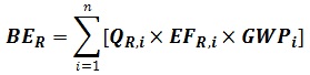
Where,
BER = Baseline scenario emissions from the destruction of eligible ODS used as a refrigerant for the reporting period (kg CO2e)
n = Total number of Types of eligible ODS
i = Type of eligible ODS
QR,i = Total quantity of eligible ODS of type i used as a refrigerant recovered and destroyed, determined in accordance with Section 7.6 (kg CO2e)
EFR,i = GHG emission rate for eligible ODS of type i used as a refrigerant, as set out in table B.2 (%)
GWPi = Global warming potential for eligible ODS of type i, as set out in Table A.1 (kg CO2e/kg ODS)
6.1.1 Determination of Deduction for Vapour Composition Risk
- The deduction for VR applies to containers that contain either mixed or pure eligible ODS.
- If the ODS Initiative includes multiple containers, with different values for VR, the value of VR shall be pro-rated according to the mass of material in each container.
- For the purposes of this Protocol, any ineligible chemical with a boiling point lower than 0°C at 1 atm is an ineligible high pressure chemical.
6.1.1.1 Low Pressure Eligible ODS
- ODS Initiatives that destroy containers which contain eligible ODS and an ineligible chemical must use Table 6.2 to determine the value of VR in Equation 6.2 for the eligible ODS listed and classified as low pressure in Column 1 of Table 6.1.
- Table 6.2 is used by identifying the value of the fill level of the liquid of the container in Column 1 and the concentration of the eligible low pressure ODS in Column 2 and the ineligible high pressure chemical in Column 3 and applying the value for VR set out in Column 4.
- The liquid fill level of the container referred to in Table 6.2 must be calculated using Equation 6.5.
| Low Pressure ODS | High Pressure ODS |
|---|---|
| CFC-11 | CFC-12 |
| CFC-113 | CFC-13 |
| CFC-114 | CFC-115 |
| HCFC-141b | HCFC-22 |
| If the value of Fillliquid is: | and the concentration of eligible low pressure ODS is: | and the concentration of ineligible high pressure chemical is: | Value for VR |
|---|---|---|---|
| > 0.70 | N/A | N/A | 0 |
| 0.50 – 0.70 | > 1% | > 10% | 0.02 |
| < 0.50 | > 1% | > 5% | 0.05 |
6.1.1.2 High Pressure Eligible ODS
- The value for VR for the eligible ODS listed and classified as high pressure in Column 2 of Table 6.1 is zero if:
- The eligible high pressure ODS is in any concentration and has a lower boiling point than the ineligible high pressure chemical, or
- The eligible high pressure ODS is in a concentration greater than that of the ineligible high pressure chemical contained in the container.
- The rules in a)1. and a)2. shall be applied in accordance with the following:
- If the container contains multiple high pressure eligible ODS, the eligible ODS with the highest concentration must be used to determine the applicability of rules a)1. and a)2..
- If the container contains multiple ineligible high-pressure chemicals, the ineligible chemical with the highest percent concentration shall be used to determine the applicability of rules a)1. and a)2.
Equation 6.5. Determining Liquid Fill Level in Container
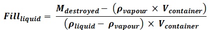
Where,
Fillliquid = Fill level of the liquid in the container (fraction)
Vcontainer = Total volume of the container (L)
Mdestroyed = Total mass of the contents of the container (kg)
ρliquid = Density of the liquid in the container at the measured temperature as determined by the Accredited Laboratory in accordance with Section 7.6 (kg/L)
ρvapour = Modeled density of the vapour in the container at the measured temperature as determined by the Accredited Laboratory in accordance with Section 7.6 (kg/L)
6.2 Calculation of Initiative Emissions
- Total ODS Initiative emissions shall be calculated using Equation 6.6.
Equation 6.6. Total ODS Initiative Emissions
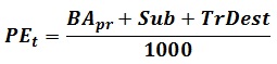
Where,
PEt = Total ODS Initiative emissions for the initiative reporting period(tCO2e)
BApr = Total emissions from the extraction of eligible ODS contained in foam for the reporting period, calculated using Equation 6.7 (kg CO2e)
Sub = Total emissions from substitute refrigerants, calculated using Equation 6.8 (kg CO2e)
TrDest = Total emissions from the transportation and destruction of eligible ODS, calculated using Equation 6.9 (kg CO2e)
1000 = Conversion from kilograms to tonnes (kgCO2e/tCO2e)
Equation 6.7. Total Emissions From the Extraction of Eligible ODS Contained in Foam
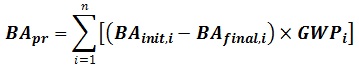
Where,
BApr = Total emissions from the extraction of eligible ODS contained in foam for the reporting period (kg CO2e)
n = Total number of Types of eligible ODS
i = Type of eligible ODS
BAinit,i = Initial quantity of eligible ODS blowing agent of type i contained in foam prior to processing, determined in accordance with Appendix C (kg ODS)
BAfinal,i = Total quantity of eligible ODS blowing agent of type i extracted and destroyed, determined in accordance with Section 7.6 (kg ODS)
GWPi = Global warming potential of eligible ODS of type i as set out in Table A.1 (kg CO2e/kg ODS)
Equation 6.8.Total Emissions From Substitute Refrigerants
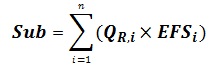
Where,
Sub = Total emissions from substitute refrigerants (kg CO2e)
n = Total number of Types of eligible ODS
i = Type of eligible ODS
QR,i = Total quantity of eligible ODS of type i used as a refrigerant recovered and destroyed, determined in accordance with Section 7.6 (kg ODS)
EFSi = Emission factor for substitutes for eligible ODS of type i as set out in Table B.3 (kg CO2e/kg ODS)
Equation 6.9. Total Emissions from Transportation and Destruction
TrDest = Qdest × 7.5
Where,
TrDest = Total emissions from the transportation and destruction of eligible ODS (kg CO2e)
Qdest = Total quantity of material (eligible and ineligible) destroyed for the reporting period, as determined in accordance with Section 7.6 and shown on the weigh tickets (kg ODS)
7.5 = Default emission factor for eligible ODS transportation and destruction (kg CO2e/kg ODS)
7. Data Management and Monitoring
7.1 Data Collection
- A data management system shall be implemented to collect, manage and store information related to the ODS Initiative in a way that ensures the integrity, exhaustiveness, accuracy and validity of the information.
- The data management system for the ODS Initiative shall include procedures to:
- Monitor the performance of the ODS Initiative and the activities associated with the ODS Initiative in accordance with Sections 7.2 – 7.7 of this Protocol;
- Manage information, including data in respect of the baseline scenario and the ODS Initiative;
- Provide the accredited verification body access to the all sites where activities associated with the ODS Initiative take place, and any other information or persons that the accredited verification body may require to verify the initiative;
- Accurately assess whether the ODS Initiative meets the applicable eligibility criteria set out in the Regulation and this Protocol;
- Identify and record any violations of legal requirements that apply to the ODS Initiative and that may have an impact on the amount of GHG reductions, avoidances or removals achieved by the ODS Initiative; and
- Assess and record a description of the impact of each violation identified under paragraph 5.
- The data management system for the initiative shall include all records required by the Regulation and this Protocol.
7.2 Extraction, Collection, Transportation and Destruction
- The Sponsor shall ensure that eligible ODS is extracted and destroyed as follows:
- Eligible ODS contained in foam must be extracted in concentrated form using a negative pressure process;
- Eligible ODS used as a refrigerant shall be collected and handled by a Certified Person, as defined in the Federal Halocarbon Regulations, 2003 as amended from time to time;
- All eligible ODS shall be collected, stored and transported in hermetically sealed containers which are approved by Transport Canada under The Transportation of Dangerous Goods Act, 1992 for the eligible ODS contained within them; and
- All eligible ODS shall be destroyed in concentrated form in a Qualified Destruction Facility meeting the requirements in Section 7.7 of this Protocol.
7.3 Point of Origin
7.3.1 Point of Origin for ODS Foam Initiatives
- The Point of Origin for eligible ODS blowing agent contained in foam shall be the facility where the eligible ODS blowing agent is extracted from the foam.
7.3.2 Point of Origin for ODS Refrigerant Initiatives
7.3.2.1 Appliances:
- The Point of Origin for eligible ODS used as a refrigerant and removed from refrigeration, freezer or air-conditioning appliances at industrial, commercial, institutional or residential locations shall be the facility where such removal occurred.
7.3.2.2 Equipment and Systems:
- Removal – Refrigerant Single – Greater than 225 kg: The Point of Origin for eligible ODS used as a refrigerant and removed in a quantity of greater than 225 kg from a single refrigeration, freezer or air-conditioning piece of equipment or system at industrial, commercial, institutional or residential locations is the piece of equipment or system the eligible ODS was removed.
- Intended for Use – Refrigerant Single – Greater than 225 kg: The Point of Origin for eligible ODS intended for use as a refrigerant and contained in a container in a quantity of greater than 225kg at an industrial, commercial, institutional or residential location is the location of the container.
- Aggregation – Greater than 225 kg: The Point of Origin for eligible ODS used as and removed from or intended for use as a refrigerant in refrigeration, freezer or air-conditioning equipment, systems at industrial, commercial, institutional or residential locations shall be the facility where the eligible ODS is aggregated to a quantity greater than 225 kg.
- Less than Or Equal to 225 kg: The Point of Origin for eligible ODS used as and removed from or intended for use as a refrigerant in refrigeration, freezer or air-conditioning equipment, systems at industrial, commercial, institutional or residential locations shall be the Qualified Destruction Facility if the total quantity of eligible ODS is less than or equal to 225 kg.
- No Documentation: If the Sponsor does not provide documentation in accordance with section 7.4 paragraph 3 of this Protocol demonstrating that that the eligible ODS used as a refrigerant was removed from or was intended for use in a refrigeration, freezer or air-conditioning piece of equipment or system at industrial, commercial, institutional or residential locations, the Point of Origin shall be the facility where the removal occurred or the containers containing the eligible ODS were located.
7.4 Data Management
- The Sponsor shall record the following information in the Monitoring Plan, and include it in any initiative reports required by the Regulation, indicating separately the information pertaining to eligible ODS contained in foam and pertaining to eligible ODS used as a refrigerant:
- A list of the facilities and entities involved in any ODS Initiative activities defined in Section 3.1 of this Protocol, from the Point of Origin to the Qualified Destruction Facility;
- Information and data required to demonstrate the requirements in Section 7.2 of this Protocol were met;
- Information on the Point of Origin required by Section 7.3 of this Protocol obtained at the time of recovery from the Point of Origin that at a minimum includes:
- The physical address of each Point of Origin;
- The name and contact information of each person involved in each stage of the ODS Initiative, and the quantity of materials, whether eligible ODS contained in foam or eligible ODS used as refrigerant, transferred, sold or handled by each party;
- For ODS Initiatives destroying eligible ODS from refrigeration, freezer or air-conditioning appliances, the number of appliances recovered and, for each appliance, the type, size, storage capacity and, if available, serial number;
- For ODS Initiatives destroying eligible ODS from systems and equipment at industrial, commercial, institutional and residential locations, the number, type, size, and, if available, serial number of the equipment or system from which the eligible ODS was recovered; and
- For eligible ODS used as and removed from or intended for use as a refrigerant in refrigeration, freezer or air-conditioning equipment or systems at industrial, commercial, institutional or residential locations, documentation demonstrating that the eligible ODS was removed from or intended for use in refrigeration, freezer or air-conditioning equipment or systems;
- The serial number or identification number of the containers used for storage and transportation of eligible ODS;
- For eligible ODS from appliances, information on eligible ODS extraction, specifying,
- The number of refrigeration, freezer or air-conditioning appliances containing foam from which eligible ODS has been extracted;
- The number of refrigeration, freezer or air-conditioning appliances containing refrigerants from which eligible ODS have been extracted;
- The name and contact information of the facility where the refrigeration, freezer or air-conditioning appliances were recycled, if any; and
- Processes, training, quality assurance and quality control measures and extraction process management processes;
- One or more Certificates of Destruction for all eligible ODS destroyed under the ODS Initiative, issued by the Qualified Destruction Facility that destroyed the eligible ODS, by destruction activity, specifying:
- The name of the Sponsor;
- The name and contact information of the Qualified Destruction Facility;
- The name and signature of the person responsible for the destruction operations at the Qualified Destruction Facility;
- The identification number on the Certificate of Destruction;
- The serial, tracking or identification number of all containers for which destruction of eligible ODS occurred;
- The weight and type of eligible ODS destroyed for each container, in kg, including the weigh tickets generated in accordance with Section 7.6 of this Protocol;
- The destruction start date and time; and
- The destruction end date and time;
- The Monitoring Parameters referred to in Section 7.5 of this Protocol;
- The certificate of sampling results issued by the Accredited Laboratory in accordance with Section 7.6 of this Protocol.
7.5 Monitoring Parameters
- Table 7.1 sets out the monitoring parameters required to be used in the calculations for each reporting period.
| Equation | Parameter | Description in Equation | Units | References |
|---|---|---|---|---|
| Equation 6.1 | ERt | TotalGHG emission reductions from the ODS initiative for the reporting period | tCO2e | Calculated |
| Equation 6.1 | BEt | Total baseline scenario emissions for the reporting period | tCO2e | Calculated using Equation 6.2 |
| Equation 6.1 | PEt | Total ODS initiative emissions for the reporting period | tCO2e | Calculated using Equation 6.6 |
| Equation 6.2 | BER | Baseline scenario emissions from the destruction of eligible ODS used as a refrigerant for the reporting period | kg CO2e | Calculated using Equation 6.4 |
| Equation 6.2 | BEF | Baseline scenario emissions from the destruction of eligible ODS contained in foam for the reporting period | kg CO2e | Calculated using Equation 6.3 |
| Equation 6.2 | VR | Deduction for vapour composition risk | % | Determined in accordance with Subsection 6.1.1 |
| Equation 6.3 Equation 6.4 Equation 6.7 Equation 6.8 |
n | Total number of Types of eligible ODS | N/A | Measured |
| Equation 6.3 Equation 6.4 Equation 6.7 Equation 6.8 |
i | Type of eligible ODS | N/A | Measured |
| Equation 6.3 Equation 6.7 Equation C.1 Equation C.2 |
BAinit,i | Initial quantity of eligible ODS blowing agent of type i contained in foam prior to processing | kg ODS | Determined in accordance with Appendix C |
| Equation 6.3 | EFF,i | GHG emission rate for eligible ODS of type i contained in foam | % | As set out in Table B.1 |
| Equation 6.3 Equation 6.4 Equation 6.7 |
GWPi | Global warming potential of eligible ODS of type i | kg CO2e/kg ODS | As set out in Table A.1 |
| Equation 6.4 Equation 6.8 |
QR,i | Total quantity of eligible ODS of type i used as a refrigerant recovered and destroyed | kg CO2e | Determined in accordance with Section 7.6 |
| Equation 6.4 | EFR,i | GHG emission rate for eligible ODS of type i used as a refrigerant | % | As set out in Table B.2 |
| Equation 6.5 | Fillliquid | Fill level of the liquid in the container | fraction | Calculated |
| Equation 6.5 | Vcontainer | Total volume of the container | L | Measured |
| Equation 6.5 | Mdestroyed | Total mass of the contents of the container | kg | Measured |
| Equation 6.5 | ρliquid | Density of the liquid in the container at the measured temperature | kg/L | As determined by the Accredited Laboratory in accordance with Section 7.6 |
| Equation 6.5 | ρvapour | Modeled density of the vapour in the container at the measured temperature | kg/L | As determined by the Accredited Laboratory in accordance with Section 7.6 |
| Equation 6.6 | BApr | Total emissions from the extraction of eligible ODS contained in foam for the reporting period | kg CO2e | Calculated using Equation 6.7 |
| Equation 6.6 | Sub | Total emissions from substitute refrigerants | kg CO2e | Calculated using Equation 6.8 |
| Equation 6.6 | TrDest | Total emissions from the transportation and destruction of eligible ODS | kg CO2e | Calculated using Equation 6.9 |
| Equation 6.7 | BAfinal,i | Total quantity of eligible ODS blowing agent of type i extracted and destroyed | kg ODS | Determined in accordance with Section 7.6 |
| Equation 6.8 | EFSi | Emission factor for substitutes for eligible ODS of type i | kg CO2e/kg ODS | As set out in Table B.3 |
| Equation 6.9 | Qdest | Total quantity of material (eligible and ineligible) destroyed for the reporting period | kg ODS | As determined in accordance with Section 7.6 and shown on the weigh tickets |
| Equation C.1 | Nn | Number of appliances, equipment and systems of type n containing eligible ODS of type i | N/A | Measured |
| Equation C.1 | Mn | Mass of eligible ODS per appliance, piece of equipment or system of type n containing eligible ODS of type i | kg | Measured |
| Equation C.2 | Foamrec | Total quantity of foam recovered prior to extraction of eligible ODS | kg ODS | Calculated |
| Equation C.2 | CBA | Concentration of eligible ODS blowing agent in the foam prior to removal from the appliance, equipment or system | kg ODS/kg foam | Calculated |
7.6 Concentrated Eligible ODS Composition and Quantity Analysis Requirements
7.6.1 Determination of the Total Quantity of Eligible ODS Sent for Destruction
- For the purposes of Equations 6.4, 6.7 and 6.8, this section sets out the method to calculate, on a mass basis, for each container, the total quantity of eligible ODS destroyed, namely the factor BAfinal,i for eligible ODS contained in foam and the factor QR,i for eligible ODS used as a refrigerant.
- Based on the mass of the eligible ODS in each container and the concentration of each sample determined in accordance with Sections 7.6.1.1 – 7.6.4, the Sponsor must calculate the factor BAfinal,i, and the factor Qi,R, by:
- Determining the quantity of each type of eligible ODS in each container;
- Deducting the weight of the water and the high boiling residue in each container; and
- Adding together the quantities of each type of eligible ODS in each container.
7.6.1.1 Determination of the Quantity of ODS in Each Container
- The quantity of eligible ODS destroyed shall be determined by weighing each container containing eligible ODS in accordance with section 7.6.1.2 of this Protocol prior to destruction and weighing the empty container immediately after destruction by a person authorized to do so at the Qualified Destruction Facility.
- The quantity of eligible ODS is equal to the difference between the mass of the container when full and when empty.
7.6.1.2 Weighing Containers
- Each container containing eligible ODS must be weighed at the Qualified Destruction Facility in accordance with the following rules:
- The same scale shall be used to weigh the container before and after destruction;
- The scale that is used shall be calibrated within three months of weighing the container intended for destruction in accordance with the following:
- The calibration of the scale shall be conducted by a Measurement Canada inspector or an authorized service provider under the Weights and Measures Act (R.S.C. 1985 c. W-6) and regulations (‘the WMA’); and
- The calibration must meet an accuracy standard applicable to that specific type of scale, as specified by Measurement Canada in the WMA;
- The container shall be weighed within 2 days prior to the commencement of the destruction of the eligible ODS contained in the container; and
- The container shall be weighed again within 2 days after the destruction of the eligible ODS contained in the container.
- Despite subparagraph a) 2., and subject to paragraph c), if the destruction of eligible ODS occurred prior to December 31, 2012 and the containers containing the eligible ODS were weighed using a scale subject to the WMA, the scale must have been calibrated in accordance with the WMA no more than 2 years prior to the weighing of the container prior to destruction.
- If the calibration performed immediately after the calibration of the scale that was performed in accordance with subparagraph a) 2 or paragraph b) indicates that the weight of the eligible ODS destroyed was overestimated, the Sponsor shall correct the overestimation by deducting the percent error recorded during the calibration from the weight calculated at the time of destruction.
7.6.2 ODS Mixing
- Containers containing eligible ODS mixtures must be circulated by an appropriately trained person who is independent from the Sponsor and the Qualified Destruction Facility, either at the Qualified Destruction Facility or prior to delivery to the Qualified Destruction Facility in accordance with the following rules:
- Liquid mixtures must be circulated from the liquid port to the vapour port of the container;
- A volume of the mixture equal to 2 times the volume in the container must be circulated;
- Circulation must occur at a rate of at least 114 litres per minute unless the mixture of eligible ODS has been circulating continuously for at least 8 hours, and has circulated more than twice the volume of the container; and
- The start and end times of the circulation must be recorded.
- The mixture of eligible ODS must be circulated in a container that meets all of the following conditions:
- The container has no solid interior obstructions other than mesh baffles or other interior structures that do not impede circulation;
- The container was fully evacuated prior to filling;
- The container must have mixing ports to circulate liquid and gas phase ODS;
- The container has ports to sample liquid and gas phase ODS;
- The sampling ports are located in the middle third of the container and not at one end or the other; and
- The container and associated equipment can circulate the mixture of eligible ODS through a closed loop system from the bottom to top.
- If a mixture of eligible ODS is transferred into a container that meets the specifications set out in paragraph b) the following rules apply:
- The mass of the mixture of eligible ODS transferred into the container must be calculated and recorded; and
- Transfers of eligible ODS between containers must be carried out at a pressure that meets the applicable standards for the jurisdiction where the transfer is occurring and for the specific chemicals being handled.
7.6.3 Sampling
- Sampling of eligible ODS contained in containers must be conducted for each container in accordance with each of the following requirements:
- If the container contains pure eligible ODS one sample shall be taken at the Qualified Destruction Facility.
- If the container contains a mixture of eligible ODS and the mixture has been circulated at the Qualified Destruction Facility, a minimum of two samples shall be taken during the last 30 minutes of circulation from the bottom of the liquid port of the container.
- If the container contains a mixture of eligible ODS and the mixture has been circulated prior to delivery to the Qualified Destruction Facility, a minimum of two samples shall be taken from the bottom of the liquid port of the container during the last 30 minutes of circulation of the mixture of eligible ODS and one additional sample shall be taken at the Qualified Destruction Facility.
- Despite subparagraph a) 3, if circulation of an eligible ODS mixture occurred prior to the delivery to the Qualified Destruction Facility and prior to December 31, 2012, a minimum of one sample of the mixture shall be taken from the bottom of the liquid port of the container during the last 30 minutes of circulation of the mixture of eligible ODS and an additional sample shall be taken at the Qualified Destruction Facility.
- When more than one sample is required to be taken for a single container, the results from the analysis of the sample with the lowest weighted global warming potential shall be used.
- Sampling must be conducted in accordance with the following requirements:
- The samples of eligible ODS shall be taken by a person who is independent of the Sponsor and of the Qualified Destruction Facility and has the appropriate training to carry out this task;
- The samples shall be taken with a clean, fully evacuated sample bottle with a minimum capacity of 0.45 kg;
- Each sample shall be taken in a liquid state;
- A minimum sample size of 0.45 kg shall be drawn for each sample; and
- Each sample shall be individually labeled and tracked in reference to the container from which it was taken.
- The following information shall be recorded for each sample taken:
- The time and date of the sample;
- The name of the Sponsor for whom the sampling was conducted;
- The name and contact information of the person who took the sample;
- The name and contact information of the employer of the person in subparagraph 3;
- The volume of the container from which the sample was taken;
- The ambient air temperature at the time of sampling; and
- The chain of custody for each sample, from the point of sampling to arrival at the Accredited Laboratory.
7.6.4 Analysis of Samples
- Samples of eligible ODS taken in accordance with section 7.6.3 of this Protocol shall be analyzed by an Accredited Laboratory to determine the following:
- The type of each eligible ODS;
- The quantity, in kilograms, of each eligible ODS of type i;
- The concentration, in kilograms of each eligible ODS of type i per kilogram of gas;
- The densities of the liquid and vapour phase components of the contents of the container using the volumetric capacity of the container;
- The internal temperature of the container at the time of sampling, if available, or if the internal temperature is not available, the ambient temperature at the time of sampling;
- In the case of mixtures of eligible ODS, the weighted concentrations of eligible ODS on the basis of their global warming potential;
- The moisture content of each sample in parts per million; and
- The high boiling residue from the sample.
- The quantities in subparagraph a)2 and the concentrations in subparagraph a)3 must be determined using gas chromatography.
- The high boiling residue from samples analyzed pursuant to subparagraph a)8 must be below 10% of the total mass of the sample.
- The moisture content determined under subparagraph a)7 must be less than 75% of the saturation point for the eligible ODS at the ambient air temperature recorded at the time the sample was taken in accordance with 7.6.3 of this Protocol.
- For samples of mixtures of eligible ODS, the saturation point for the mixture shall be the lowest saturation point of the eligible ODS species in the mixture that is at least 10% of the mixture by mass.
- If the moisture content of a sample of either a pure or mixture of eligible ODS is 75% or more, the Sponsor must dry the eligible ODS and take and analyze a sample of the dried eligible ODS it in accordance with the method in Section 7.6.3 of this Protocol and this section.
- The Sponsor shall obtain a certificate of the sampling results issued by the Accredited Laboratory that conducted the analysis of the sample.
7.7 Qualified Destruction Facilities
7.7.1 Operations
- The Sponsor shall ensure and demonstrate each of the following:
- The Qualified Destruction Facility uses a destruction technology that is approved under the Montreal Protocol
footnote 9 and that results in the complete breakdown of the eligible ODS into either a waste or usable by-product and achieves greater than 99.99% Destruction and Removal Efficiency (DRE). - The Qualified Destruction Facility meets or exceeds the standards set out by the UN Environment Programme Technology and Economic Assessment Panel (TEAP) Task Force on Destruction in the Report of the Task Force on Destruction Technologies.
footnote 10 . - The operating parameters for the Qualified Destruction Facility during destruction of eligible ODS were monitored and recorded in accordance with the Code of Good Housekeeping approved by the Montréal Protocol.
footnote 11 - The Qualified Destruction Facility has conducted comprehensive performance testing at least once every three years following the first performance testing that was conducted for the Qualified Destruction Facility in order to confirm compliance with the TEAP DRE and emissions limits.
- The Qualified Destruction Facility provides third-party certified results to the Sponsor indicating that the facility meets all performance criteria set out in the Code of Good Housekeeping.
- The Qualified Destruction Facility met all applicable legal requirements during the destruction of eligible ODS.
- The Qualified Destruction Facility uses a destruction technology that is approved under the Montreal Protocol
- The Sponsor shall ensure and demonstrate that each of the following parameters are continuously monitored at the Qualified Destruction Facility during the eligible ODS destruction process:
- The feed rate of the eligible ODS.
- The operating temperature and pressure of the Qualified Destruction Facility.
- Effluent discharges measured in terms of water and pH levels.
- Carbon monoxide emissions.
7.7.2 Certificates of Destruction
- A Sponsor of an ODS Initiative shall provide one or more Certificates of Destruction issued by a Qualified Destruction Facility certifying and documenting the destruction of the entire quantity of eligible ODS.
- A Sponsor of an ODS Initiative shall provide one or more Certificates of Destruction certifying and documenting that the eligible ODS was destroyed within 5 years of the collection or recovery of the eligible ODS.
- A Certificate of Destruction may include eligible ODS from single or multiple Points of Origin.
- Multiple Certificates of Destruction may be used for a single ODS Initiative.
- Amounts of eligible ODS documented in a Certificate of Destruction that has been issued for an ODS Initiative are not eligible to be included in another Certificate of Destruction issued for an ODS Initiative.
8. Reversals
8.1 Reversals Listed for the Purposes of s. 20(1) paragraph 1
- There are no reversals listed in this protocol for the purpose of s. 20(1) paragraph 1 of O.Reg. 539/17.
8.2 Errors, Omissions or Misstatements
- In the event that an error, omission or misstatement is discovered after Ontario offset credits have been created and issued for a reporting period, the Sponsor shall determine the total amount of the reversal by:
- Using this protocol to re-calculate the corrected value of the GHG emission reductions from the ODS Initiative for the reporting period for each initiative report affected by the reversal.
- Calculating the total reversal of GHG emission reductions from the ODS Initiative using Equation 8.1.
Equation 8.1. Calculating GHG Emission Reductions Reversed
Where,
RE = GHG emission reductions reversed (tCO2e)
n = Total number of initiative reports affected by the reversal
r = Initiative reports affected by the reversal
ERc = Corrected GHG emission reductions from the ODS Initiative for the reporting period calculated in accordance with Subsection 8.2(a)(1) (tCO2e)
ERi = Initially reported GHG emission reductions from the ODS Initiative for the reporting period (tCO2e)
9. Reporting
- The following information shall be set out in an initiative report or a reversal report in addition to the information required by the Regulation.
9.1 Initiative Report
9.1.1 Eligibility Criteria Information
- The location of the ODS Initiative.
- The duration of the ODS Initiative.
- The types of eligible ODS destroyed by the ODS Initiative.
9.1.2 Monitoring Information
- A description of how the ODS Initiative was monitored, including the following:
- A statement of whether the monitoring performed meets the requirements set out in Section 7 of this Protocol; and
- Where applicable, an identification of any deviations from the requirements set out in Section 7 of this Protocol and a description of whether these deviations should be considered material.
- Calibration certificates or verification reports on the calibration accuracy of each weigh scale.
- Identification of the measurement frequency used for each monitoring parameter identified in Section 7.5 of this Protocol.
- Information required in accordance with Section 7 of this Protocol.
- All Certificates of Destruction.
- All certificates of analysis issued by the Accredited Laboratory for the ODS Initiative.
9.1.3 Quantification Information
- All calculations set out in Section 6 of this Protocol, including any supporting calculations set out in Section 7 and Appendix C of this Protocol, that were used.
- The types of substitute refrigerants used if any.
9.2 Reversal Report
9.2.1 General
- Information about the circumstances and causes of the reversal including the number of reporting periods affected.
- For each initiative report that was affected by the reversal, all information that has changed as a result of the reversal and a description of those changes.
- In the case of an error, omission or misstatement reversal, a description of the corrective actions taken to address the circumstances and causes of the reversal.
- Supporting documentation for each of the items in paragraphs (a) through (c) above including any Certificates of Destruction and Certificates of Analysis issued for the ODS Initiative by the Accredited Laboratory.
9.2.2 Quantification Information
- All calculations set out in Section 8 of this Protocol, including supporting calculations set out in Section 6, Section 7 and Appendix C, of this Protocol that were used to determine the amount of the reversal.
- Supporting documentation related to the calculations.
10. Record Keeping
- The following records and documents shall be kept in addition to the records that are required to be kept under the Regulation:
- The name and contact information for any facilities or enterprises that carried out the following activities, as they apply to the ODS Initiative;
- Recovery and extraction of the eligible ODS blowing agent contained in foam;
- Recovery of eligible ODS used as a refrigerant;
- Destruction of eligible ODS;
- Mixing of eligible ODS; and
- Certificates of analysis issued by an Accredited Laboratory for all eligible ODS samples;
- The information and data required under the monitoring requirements in Section 7 of this Protocol, including all GHG calculations and related data inputs;
- All documentation related to any violations of legal requirements that apply to the ODS Initiative or that may have an impact on the amount of GHG reductions, avoidances or removals achieved by the ODS Initiative;
- A description of the methods used to remove foam or eligible ODS used as a refrigerant from the refrigeration, freezer or air-conditioning appliances, systems and equipment; and
- A description of the methods used to extract the eligible ODS from the foam.
- The name and contact information for any facilities or enterprises that carried out the following activities, as they apply to the ODS Initiative;
11. Verification Site Visits
- For the purposes of s. 22 (1) of the Regulation, site means:
- The Point of Origin;
- The Qualified Destruction Facility; and
- ODS mixing and sampling facility (if applicable).
Appendix A: Global Warming Potential of ODS
| Type of ODS | Global Warming Potential kg CO2 equivalent per kg ODS |
|---|---|
| CFC-11 | 4,750 |
| CFC-12 | 10,900 |
| CFC-13 | 14,400 |
| CFC-113 | 6,130 |
| CFC-114 | 10,000 |
| CFC-115 | 7,370 |
| HCFC-22 | 1,810 |
| HCFC-141b | 725 |
Appendix B: ODS Emission Factors
| Type of ODS | Emission Rate for Each Type of ODS Contained in Foam (EFF,i) |
|---|---|
| CFC-11 | 0.44 |
| CFC-12 | 0.55 |
| HCFC-22 | 0.75 |
| HCFC-141b | 0.50 |
| Type of ODS | Emission Rate for Each Type of ODS Contained Used or Intended for Use as a Refrigerant (EFF,i) |
|---|---|
| CFC-11 | 0.89 |
| CFC-12 | 0.95 |
| CFC-13 | 0.61 |
| CFC-113 | 0.89 |
| CFC-114 | 0.78 |
| CFC-115 | 0.61 |
| ODS Used as Refrigerants | Emission Factors for Substitute Refrigerants (EFSi) (CO2e/ODS) |
|---|---|
| CFC-11 | 223 |
| CFC-12 | 686 |
| CFC-13 | 7,144 |
| CFC-113 | 220 |
| CFC-114 | 659 |
| CFC-115 | 1,139 |
Appendix C: Calculations for Foam Blowing Agent Recovery
- In order to calculate baseline scenario and initiative emissions related to recovery of foam blowing agent, in accordance with Section 6 of this Protocol, the Sponsor shall first calculate the quantity of eligible ODS contained in foam prior to its removal from refrigeration, freezer or air-conditioning appliances, systems and equipment.
C.1. Calculation Methods for the Initial Quantity of ODS Contained in Foam
- Sponsors shall determine the initial quantity of eligible ODS contained in foam:
- Using Equation C.1 in accordance with Section C.2; or,
- Using Equation C.2 in accordance with Section C.3
C.2. Calculation of the Initial Quantity of Eligible ODS Contained in Foam Based on Storage Capacity
Equation C.1. Initial Quantity of Eligible ODS Contained in Foam Prior to Removal (default values)
Where,
BAinit,i = Initial quantity of eligible ODS blowing agent type i contained in foam prior to processing (kg ODS)
Nn = Number of appliances, equipment and systems of type n containing eligible ODS of type i
Mn = Mass of eligible ODS per appliance, equipment or system of type n containing eligible ODS of type i as set out in Table C.1 (kg)
| Type of Appliance | >Storage Capacity (SC) | >Mass of ODS per Appliance (kg) |
|---|---|---|
| Type 1 | SC < 180 litres | 0.24 |
| Type 2 | 180 litres ≤ SC < 350 litres | 0.32 |
| Type 3 | 350 litres ≤ SC < 500 litres | 0.4 |
| Type 4 | SC ≥ 500 litres | 0.48 |
C.3. Calculation of the Initial Quantity of Eligible ODS Contained in Foam Based on Samples
C.3.1. Calculation
Equation C.2. Initial Quantity of Eligible ODS Contained in Foam Prior to Removal (site-specific)
BAinit,i = Foamrec× CBA
Where,
BAinit,i = Initial quantity of eligible ODS blowing agent of type i contained in foam prior to processing (kg ODS)
Foamrec = Total quantity of foam recovered prior to extraction of eligible ODS (kg ODS)
CBA = Concentration of eligible ODS blowing agent in the foam prior to removal from the appliance, equipment or system (kg ODS/kg foam)
- The calculation in C.2 shall be conducted once per ODS Initiative based on a minimum of 10 appliances, equipment or systems.
- The CBA factor used in Equation C.2 is determined by calculating the 90% upper confidence limit of eligible ODS concentration in the foam samples taken from each appliance, equipment or system.
- The Foamrec term used in Equation C.2 is determined by:
- Using a default value of 5.85 kg per appliance, equipment or system and multiplying it by the number of appliances, equipment or systems sampled; or
- Using the following method:
- Separate and collect all foam residual from the appliance, equipment or system
- Separate the foam components from the residual referred to in i.; and
- Weigh the foam residual prior to extraction of the eligible ODS from the foam.
- The Sponsor must demonstrate and document that a significant quantity of foam residual is not emitted or diverted to waste streams.
C.3.2. Sampling
- Samples from at least 10 refrigeration, freezer or air-conditioning appliances, equipment or systems must be taken and analyzed by an Accredited Laboratory in accordance Section 7.6 of this Protocol and in accordance with the following method:
- Cut 4 foam samples that are at least 10 cm2 and the full thickness of the foam from the left side, right side, top and bottom of each appliance equipment or system using a reciprocating saw;
- Seal the cut edges of each sample referred to in subparagraph 1 using aluminum tape or a similar product that prevents off gassing;
- Record the model of the appliance, equipment or system on a label affixed to each sample;
- Record the location where each sample was taken (i.e. left, right, top, bottom) on a label affixed to each sample;
- Analyze each sample using the procedure set out in paragraph c); and
- Calculate the quantity of each type of eligible ODS recovered by dividing the total mass of the initial foam samples prior to analysis to determine the mass ratio of eligible ODS present, in kg of eligible ODS per kg of foam.
- The analysis required under subparagraph a) 5 may be conducted by analyzing each of the four samples from each appliance, equipment or system individually or by combining equal masses of foam from each of the four samples into one sample.
- The following are the requirements for laboratory analysis of the eligible ODS concentration from each foam sample:
- The analysis of the content and mass ratio of the eligible ODS contained in foam must be done at an Accredited Laboratory in accordance with Section 7.6 of this Protocol;
- The analysis must be done using the heating method to extract eligible ODS from the foam in the foam samples, as described in the article “Release of fluorocarbons from Insulation foam in Home Appliance during Shredding” published by Scheutz, Fredenslund, Kjeldsen and Tant in the Journal of the Air & Waste Management Association (December 2007, Vol. 57, pages 1452-1460), and in accordance with the requirements set out below:
- Each foam sample must be no more than 1 cm thick and shall be analysed in accordance with the following steps:
- Place each sample in a 1123 ml glass bottle, sealed with Teflon-coated septa and aluminum caps and weighed using a calibrated scale;
- Incubate each sample in an oven for 48 hours at 140°C;
- Cool each sample to room temperature;
- Draw gas samples drawn from the headspace and analyze each gas sample using gas chromatography in accordance with Section 7.6 of this Protocol;
- Remove the septa and caps after the analysis;
- Flush the headspace with atmospheric air for approximately 5 minutes using a compressor;
- Replace the septa and caps;
- Heat the bottles for a second 48-hour period;
- Cool each sample down to room temperature; and
- Draw gas samples from the headspace and analyze each gas sample using gas chromatography in accordance with Section 7.6 of this Protocol.
- Each foam sample must be no more than 1 cm thick and shall be analysed in accordance with the following steps:
Mine Methane Capture Initiative Protocol
Capture and Destruction of Mine Methane from Drainage and Ventilation Systems at Active Coal Mines
Protocol Version 1
Dated April 12, 2018
1. Introduction
This Protocol sets out the requirements that will enable a sponsor to undertake a mine methane capture (MMC) greenhouse gas (GHG) reduction initiative for the purpose of registering and receiving offset credits in Ontario’s cap and trade program.
The following sections outline the definition of an MMC GHG reduction initiative, the specific eligibility criteria, baseline scenario and initiative calculation methods, monitoring, data management and reporting requirements that apply to MMC GHG reduction initiatives.
2. Definitions
- Abandoned coal mine
- means a mine where all mining activity including mine development and coal production have ceased, mine personnel are not present in the mine workings, and mine ventilation fans are no longer operative.
- Active coal mine
- means any underground or surface mine with mine works that are actively ventilated by the mine operator and which has the primary purpose of being used in extracting coal from its natural deposits in the earth by any means or method but, does not include an abandoned coal mine or a mountain top removal mine.
- Coal
- means all solid fuels classified as anthracite, bituminous, subbituminous, or lignite under ASTM D388, entitled Standard Classification of Coals by Rank.
- Coal bed methane (CBM)
- means methane originating in coal seams that is drained from virgin coal seams and surrounding strata.
- Drainage system
- means a term used to encompass the entirety of the equipment that is used to drain mine gas from underground and collect it at a common point, including a vacuum pumping stations, surface pre-mining, horizontal pre-mining, and post-mining.
- Eligible destruction device
- means a device that is set out in Table A.1 of this Protocol.
- GHG assessment boundary
- means all the GHG sources, sinks and reservoirs (SSRs) that are required to be assessed because they are identified as included in Table 5.1.
- Gob
- means the collapsed area of strata produced by the removal of coal and artificial supports behind a working coalface. Strata above and below the gob are de-stressed and fractured by the mining activity.
- Ineligible destruction device
- means a device that is not an eligible destruction device or is an eligible destruction device that was in use prior to a start up or testing period.
- Longwall mine
- means an underground mining type that uses at least one longwall panel during coal excavation.
- Mine
- means an area of land and all structures, facilities, machinery tools, equipment, shafts, slopes, tunnels, excavations, and other property, real or personal, placed upon, under, or above the surface of such land by any person, used in, or to be used in, or resulting from, the work of extracting minerals. The mine boundaries are defined by the mine area as permitted by the province in which the mine is located.
- Mine gas (MG)
- means the untreated gas extracted from within a mine.
- Mine methane (MM)
- means the methane portion of the mine gas contained in coal seams and surrounding strata that is released because of mining operations.
- Mined through
- means the following:
- A borehole at a surface or underground mine where the linear distance between the endpoint of the borehole and the working face of the mine that will pass nearest the endpoint of the borehole has reached an absolute minimum;
- A well at a surface or underground mine that is physically bisected by mining activities;
- A well at a surface or underground mine that produces elevated amounts of atmospheric gases so that the concentration of nitrogen in the mine gas increases by 5% compared to baseline concentrations according to a gas analysis using a gas chromatograph completed by an ISO 17025 accredited laboratory and the oxygen concentration has not increased by the same proportion as the nitrogen concentration;
- The working face of an underground mine passes less than 150 m below a well; or
- The block of coal that will be left unmined as a pillar at an underground room and pillar mine is less than 150 m directly below the well.
- Monitoring device
- means any device used to monitor the MMC collection system and eligible or ineligible destruction devices (e.g., flow meters, methane (CH4) analyzers, temperature sensors, thermocouples, etc.).
- Oxidizer
- for the purposes of this Protocol, refers to technology for destruction of ventilation air methane with or without utilization of thermal energy and with or without a catalyst.
- Room and pillar mine
- means an underground mine where approximately half of the coal is left in place as square or rectangular “pillars” to support the roof of the active mining area while “rooms” of coal are extracted, laid out in a checkerboard fashion.
- Ventilation air (VA)
- means air from a mine ventilation system.
- Ventilation air methane (VAM)
- means the mine methane that is mixed with the ventilation air in a mine.
- Ventilation system
- means a system that is used to control the concentration of mine methane and other deleterious gases within mine working areas.
3. Mine Methane Capture GHG Reduction Initiative
3.1 Initiative Definition
- The Mine Methane Capture GHG reduction initiative (‘the MMC Initiative’) is defined as an initiative that uses an eligible destruction device (or multiple eligible destruction devices) to destroy mine methane captured from:
- A drainage system at an active coal mine in Canada and is further defined in Sections 3.1.1 and 3.1.2 of this Protocol (“Drainage Initiative”); or
- A ventilation system of an active underground coal mine in Canada and is further defined in Sections 3.1.1 and 3.1.3 of this Protocol (“Ventilation Air Methane (VAM) Initiative”).
3.1.1 Mine Boundaries
- The mine boundaries of the MMC Initiative are defined by the mine area or mine map approved by the regulator in the Province in which the mine is located as well as the following:
- For Drainage Initiatives at active underground mines, the area where mine methane contained in mine gas is extracted from strata up to 150 meters above and 50 meters below a mined seam using one of the following methods:
- Pre-mining surface wells;
- Pre-mining in-mine boreholes; or
- Gob wells.
- For Drainage Initiatives at active surface mines, the area where mine methane contained in mine gas is extracted from all strata above and up to 50 meters below a mined seam using one of the following methods:
- Pre-mining surface wells;
- Pre-mining in-mine boreholes;
- Existing coal bed methane wells that would otherwise be shut-in and abandoned as a result of encroaching mining;
- Abandoned wells that are reactivated; or
- Converted dewatering wells.
- For VAM Initiatives at active underground mines, that include a drainage system:
- The area where mine methane contained in mine gas is extracted from strata up to 150 meters above and 50 meters below a mined seam using a drainage system to supplement air collected from a ventilation system from a mine; and
- The ventilation system.
- For Drainage Initiatives at active underground mines, the area where mine methane contained in mine gas is extracted from strata up to 150 meters above and 50 meters below a mined seam using one of the following methods:
3.1.2 Drainage Initiatives
3.1.2.1 Requirements
- A Drainage Initiative is an MMC Initiative that uses a drainage system in an active coal mine to drain mine gas from coal seams using any of the following extraction methods:
- Surface boreholes drilled using vertical or surface-to-seam directional drilling and located within the mine boundaries used to capture pre-mining mine methane;
- In-mine underground horizontal boreholes located within the mine boundaries used to capture pre-mining mine methane; or
- Surface gob wells, other gob mine methane capture techniques, underground boreholes, or gas drainage galleries located within the mine boundaries to capture post-mining mine methane, including mine methane from sealed areas.
- Multiple Drainage Initiatives may be implemented at a single mine.
3.1.2.2 Application for Registration
- The following additional information must be included in the application for registration of a Drainage Initiative under s. 7 of the Regulation:
- A description of the borehole(s) that make up the Drainage Initiative’s drainage system;
- A description of the eligible destruction device(s) for the Drainage Initiative; and
- A diagram detailing the boreholes and eligible destruction devices for the Drainage Initiative.
3.1.2.3 Updated Information – Expansions:
- The Sponsor shall update the information required to be submitted in section 3.1.2.2 of this Protocol if any one of the following activities occurs:
- A new borehole is connected to an existing eligible destruction device;
- An existing borehole is connected to an existing eligible destruction device;
- An additional eligible destruction device is added to a borehole that is already connected to an existing eligible destruction device; or
- A new borehole or an existing borehole is connected to a new eligible destruction device.
- The Sponsor may apply to register a new initiative for activities described in paragraph 4 of 3.1.2.3.a)
3.1.3 Ventilation Air Methane (VAM) Initiatives
3.1.3.1 Requirements
- A Ventilation Air Methane (VAM) Initiative is an MMC Initiative that destroys mine methane that would otherwise be vented from a ventilation shaft or multiple shafts that are operating concurrently and which are part of the mine’s ventilation system.
- Multiple VAM Initiatives may be implemented at a single mine.
3.1.3.2 Application for Registration
- The following information must be included in the application for registration of the initiative submitted under s. 7 of the Regulation:
- A description of the ventilation shaft(s) for the VAM Initiative;
- A description of the eligible destruction device(s) for the VAM Initiative; and
- A diagram detailing the ventilation shaft(s) and eligible destruction device(s) for the VAM Initiative.
3.1.3.3 Updated Information – Expansions:
- The Sponsor shall update the information required to be submitted in section 3.1.3.2 of this Protocol if one of the following activities occurs:
- A new or additional eligible destruction device is added to a shaft that is part of a registered VAM Initiative; or
- A new or additional eligible destruction device is added to a new shaft that is not part of a registered VAM Initiative.
- The Sponsor may apply to register a new initiative for activities described in paragraph 2 of Section 3.1.3.3.a) this Protocol.
3.1.4 Destruction – MMC Initiatives:
- Subject to paragraph 1, mine methane captured from mine gas at an MMC Initiative must be destroyed at the active coal mine where it was captured using an eligible destruction device.
- Mine methane captured from mine gas by an MMC Initiative that uses pipeline injection as the eligible destruction device may destroy the mine methane captured at a location other than the active coal mine where the mine methane was captured.
3.2 Initiative Start Date
- The start date of an MMC Initiative is defined in s. 2 of the Regulation and is determined as follows: If reductions from the initiative are first achieved during a start-up or testing period, the start date occurs after the end of the start-up or testing period, which period cannot exceed six (6) months.
4. Eligibility
- The following activities are not eligible to be considered a part of an MMC Initiative under this Protocol:
- Mine methane capture at abandoned coal mines.
- Destruction of coal bed methane.
- Mine methane captured outside the mine boundaries.
- Drainage systems that use CO2, steam or any other fluid or gas to enhance mine methane drainage.
- Mine methane capture at a mountain top removal mine.
4.1 General Requirements
- A legal requirement to destroy mine methane from the mine must not be applicable to the mine.
- An MMC Initiative must capture and destroy mine methane that, in the absence of the MMC Initiative, would have been emitted to the atmosphere.
4.2 Location
- An MMC Initiative must be implemented at an active coal mine located in Canada.
5. GHG Assessment Boundary
- The following SSRs have been considered in determining the GHG Assessment Boundary:
- Figure 5.1 illustrates all relevant GHG SSRs associated with Drainage Initiative activities and delineates the GHG Assessment Boundary.
- Figure 5.2 illustrates all relevant GHG SSRs associated with VAM initiative activities and delineates the GHG Assessment Boundary.
- Table 5.1 provides greater detail on each relevant GHG SSR and justification for their inclusion or exclusion from the GHG Assessment Boundary.
Figure 5.1. GHG Assessment Boundary for Drainage Initiatives at Active Underground and Active Surface Mines
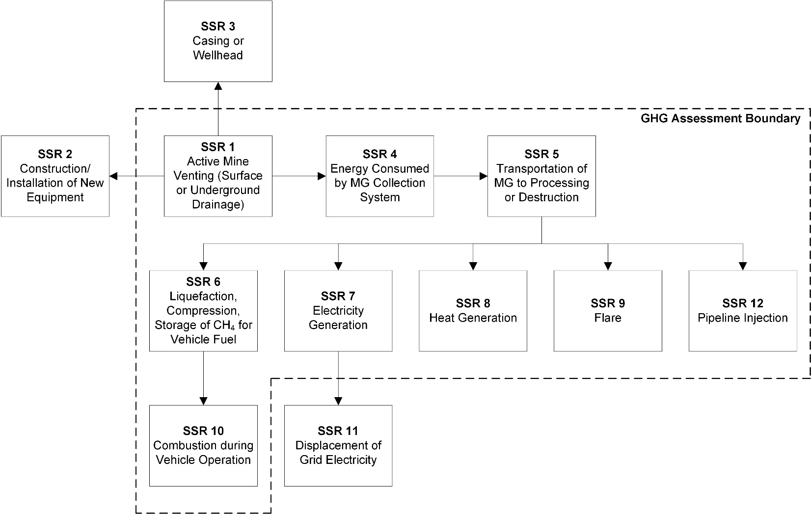
Figure 5.2. GHG Assessment Boundary for VAM Initiatives at Active Underground Mines
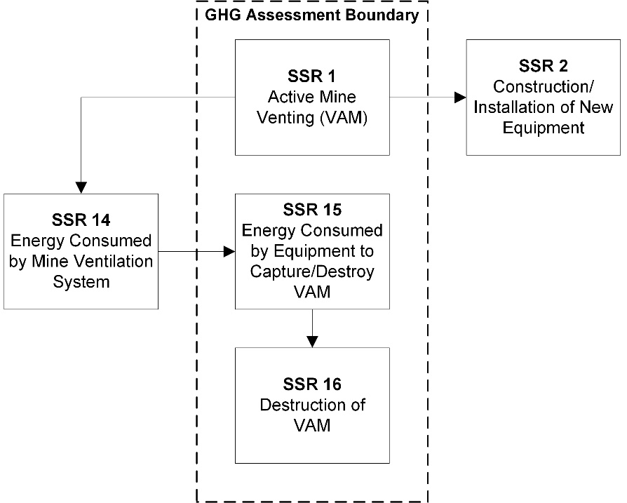
| SSR | Source Description | GHG | Relevant to Baseline Scenario (B) or Initiative (I) | Included or Excluded | Justification/Explanation |
|---|---|---|---|---|---|
| 1 | Active mine – emissions as a result of venting (Surface or Underground Drainage, or VAM Initiative) | CH4 | B, I | Included | Primary source of GHG emissions in the baseline scenario. Monitored and calculated based on destruction in ineligible and eligible destruction devices. |
| 2 | Emissions from construction and/or installation of new equipment | CO2 | B, I | Excluded | This emission source is assumed to be very small. |
| 2 | Emissions from construction and/or installation of new equipment | CH4 | B, I | Excluded | This emission source is assumed to be very small. |
| 2 | Emissions from construction and/or installation of new equipment | N2O | B, I | Excluded | This emission source is assumed to be very small. |
| 3 | Fugitive emissions resulting from casing or wellhead | CH4 | B, I | Excluded | GHG emissions from this source are assumed to be equal in the baseline scenario and the Drainage Initiative. |
| 4 | Emissions resulting from energy consumed by additional equipment used to capture, treat, or destroy mine gas, including the drilling of additional wells | CO2 | B, I | Included | The Drainage Initiative may use additional equipment beyond what is required in the baseline scenario.. Energy used by equipment installed for the safety of the mine shall be excluded. |
| 4 | Emissions resulting from energy consumed by additional equipment used to capture, treat, or destroy mine gas, including the drilling of additional wells | CH4 | B, I | Excluded | This emission source is assumed to be very small. |
| 4 | Emissions resulting from energy consumed by additional equipment used to capture, treat, or destroy mine gas, including the drilling of additional wells | N2O | B, I | Excluded | This emission source is assumed to be very small. |
| 4 | Fugitive emissions resulting from compressors, blowers, and/or gathering system | CH4 | B, I | Excluded | Fugitive methane released prior to reaching the flow meter is assumed to have been released in the baseline scenario. |
| 5 | Fuel consumption for transport of mine gas (MG) to processing or Destruction equipment | CO2 | B, I | Included | The Drainage Initiative may use additional equipment beyond what is required in the baseline scenario. |
| 5 | Fuel consumption for transport of mine gas (MG) to processing or Destruction equipment | CH4 | B, I | Excluded | This emission source is assumed to be very small. |
| 5 | Fuel consumption for transport of mine gas (MG) to processing or Destruction equipment | N2O | B, I | Excluded | This emission source is assumed to be very small. |
| 6 | Emissions resulting from liquefaction, compression, or storage of methane for vehicle fuel | CO2 | B, I | Included | The Drainage Initiative may use additional equipment beyond what is required in the baseline scenario. |
| 6 | Emissions resulting from liquefaction, compression, or storage of methane for vehicle fuel | CH4 | B, I | Excluded | The Drainage Initiative may use additional equipment beyond what is required in the baseline scenario. |
| 6 | Emissions resulting from liquefaction, compression, or storage of methane for vehicle fuel | N2O | B, I | Excluded | The Drainage Initiative may use additional equipment beyond what is required in the baseline scenario. |
| 7 | Emissions from methane destruction for electricity generation | CO2 | B, I | Included | If mine methane is used for on-site power generation, initiative will result in increased CO2 emissions from the destruction of methane to generate power. This source is also included where mine methane is sent to a ineligible destruction device for electricity generation. |
| 7 | Emissions from methane destruction for electricity generation | N2O | B, I | Excluded | This emission source is assumed to be very small. |
| 7 | Emissions of uncombusted methane | CH4 | B, I | Included | If mine methane is used for on-site power generation, Drainage Initiative will result in increased methane emissions from incomplete combustion. This source is also included where mine methane is sent to an ineligible destruction device for electricity generation. |
| 8 | Emissions from methane destruction for heat generation | CO2 | B, I | Included | If mine methane is used for on-site thermal energy generation, Drainage Initiative will result in increased CO2 emissions from the destruction of methane to generate energy. This source is also included where mine methane is sent to an ineligible destruction device to generate energy. |
| 8 | Emissions from methane destruction for heat generation | N2O | B, I | Excluded | This emission source is assumed to be very small. |
| 8 | Emissions of uncombusted methane | CH4 | B, I | Included | If mine methane is used for on-site thermal energy generation, initiative will result in increased methane emissions from incomplete combustion. This source is also included where mine methane is sent to an ineligible device to generate energy. |
| 9 | Emissions from methane destruction using a flare | CO2 | B, I | Included | If mine methane is sent to a flare, Drainage Initiative will result in increased CO2 emissions from the destruction of methane in flare. This source is also included where mine methane is sent to an ineligible destruction device for flaring. |
| 9 | Emissions from methane destruction using a flare | N2O | B, I | Excluded | This emission source is assumed to be very small. |
| 9 | Emissions of uncombusted methane | CH4 | B, I | Included | If mine methane is sent to a flare, initiative will result in increased methane emissions from incomplete combustion. This source is also included where mine methane is sent to an ineligible destruction device for flaring. |
| 10 | Emissions resulting from combustion during vehicle operation | CO2 | B, I | Included | If MM is used to produce CNG/LNG to fuel vehicle operation, Drainage Initiative will result in increased CO2 emissions from the destruction of methane in vehicles. |
| 10 | Emissions resulting from combustion during vehicle operation | N2O | B, I | Excluded | This emission source is assumed to be very small. |
| 10 | Emissions resulting from incomplete combustion during vehicle operation | CH4 | B, I | Included | If MM is used to produce CNG/LNG to fuel vehicle operation, Drainage Initiative will result in increased methane emissions from incomplete combustion. |
| 11 | Emission reductions resulting from the displacement of fossil fuels or electricity | CO2 | B, I | Excluded | This protocol does not cover displacement of GHG emissions from the use of MM for grid-connected electricity generation. |
| 11 | Emission reductions resulting from the displacement of fossil fuels or electricity | CH4 | B, I | Excluded | This protocol does not cover displacement of GHG emissions from the use of MM for grid-connected electricity generation. |
| 11 | Emission reductions resulting from the displacement of fossil fuels or electricity | N2O | B, I | Excluded | This protocol does not cover displacement of GHG emissions from the use of MM for grid-connected electricity generation. |
| 12 | Emissions resulting from the combustion of methane by end-users after it has been injected into a pipeline | CO2 | B, I | Included | If mine methane is injected into a pipeline, initiative will result in increased CO2 emissions from the destruction of methane. |
| 12 | Emissions resulting from the combustion of methane by end-users after it has been injected into a pipeline | N2O | B, I | Excluded | This emission source is assumed to be very small. |
| 12 | Emissions of uncombusted methane injected into a pipeline | CH4 | B, I | Included | If mine methane is injected into a pipeline, Drainage Initiative will result in increased methane emissions from incomplete combustion. |
| 14 | Emissions attributable to energy consumed to operate mine ventilation system | CO2 | B, I | Excluded | GHG emissions from this source are assumed to be equal in the baseline scenario and VAM Initiative. |
| 14 | Emissions attributable to energy consumed to operate mine ventilation system | CH4 | B, I | Excluded | GHG emissions from this source are assumed to be equal in the baseline scenario and VAM Initiative. |
| 14 | Emissions attributable to energy consumed to operate mine ventilation system | N2O | B, I | Excluded | GHG emissions from this source are assumed to be equal in the baseline scenario and VAM Initiative. |
| 15 | Emissions attributable to energy consumed to operate equipment to capture and destroy VAM | CO2 | B, I | Included | The Ventilation System will result in increased combustion emissions due to energy consumption from equipment used to capture and destroy VAM. |
| 15 | Emissions attributable to energy consumed to operate equipment to capture and destroy VAM | CH4 | B, I | Excluded | This emission source is assumed to be very small. |
| 15 | Emissions attributable to energy consumed to operate equipment to capture and destroy VAM | N2O | B, I | Excluded | This emission source is assumed to be very small. |
| 16 | Emissions from the destruction of VAM | CO2 | B, I | Included | VAM Initiative will result in increased CO2 emissions from the oxidation of methane in ventilation air. |
| 16 | Emissions from the destruction of VAM | N2O | B, I | Excluded | This emission source is assumed to be very small. |
| 16 | Emissions of uncombusted VAM | CH4 | B, I | Included | VAM Initiative will result in methane emissions from non-oxidized methane from the ventilation air. |
6. Calculation of Emission Reductions
- Reductions of GHG emissions from the MMC Initiative during a reporting period shall be calculated in accordance with Equation 6.1.
- GHG emission reductions shall not be calculated for any period during a reporting period in which:
- The device monitoring an eligible destruction device was not operating; or
- The eligible destruction device was not operating.
Equation 6.1. GHG Emission Reductions
ER = BE − PE
Where,
ER = GHG emission reductions from the MMC Initiative during the reporting period (tCO2e)
BE = Baseline scenario emissions during the reporting period, calculated using Equation 6.2 for Drainage Initiatives or Equation 6.10 for VAM Initiatives (tCO2e)
PE = Initiative emissions during the reporting period, calculated using Equation 6.5 for Drainage Initiatives or Equation 6.11 for VAM Initiatives (tCO2e)
6.1 Calculation of Emission Reductions from Drainage Initiatives
6.1.1 Calculation of Baseline Emissions from Drainage Initiatives
- Baseline scenario emissions of the Drainage Initiative for a reporting period shall be calculated in accordance with Equation 6.2.
Equation 6.2. Calculating Baseline Emissions
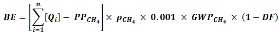
Where,
BE = Baseline scenario emissions during the reporting period (tCO2e)
n = Number of eligible destruction devices
i = Eligible destruction device
Qi = Total quantity of methane sent to eligible destruction device i during the reporting period, calculated using Equation 6.3 (m3 CH4)
PPCH4 = Volume of methane that would have been sent to all ineligible destruction devices during the reporting period, calculated using Equation 6.4. (m3 CH4)
ρCH4 = Density of methane at the reference temperature, as set out in Table A.2 (kg CH4/m3 CH4)
0.001 = Conversion factor, kilograms to tonnes (tCH4/kg CH4)
GWPCH4 = Global Warming Potential for CH4, as set out in O.Reg. 143/16 (tCO2e/tCH4)
DF = Discount factor is 0 or 0.1, determined in accordance with Section 7.2.3Equation 6.3. Baseline Methane Released to Atmosphere
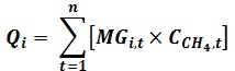
Where,
Qi = Total quantity of methane sent to eligible destruction device i during the reporting period (m3 CH4)
n = Number of measurement periods
t = Measurement period as set out in Table 7.1
MGi,t = Volume of mine gas sent to eligible destruction device i in measurement period t (m3)
CCH4,t = Average methane content in the mine gas, for the measurement period t (m3 CH4/m3 MG) - The value for MGi,t for Equation 6.3, 6.8, 6.9 and 7.1 includes the following mine gas only after the surface well has been mined through:
- All mine gas from the surface well sent to the eligible destruction device during the reporting period during which the surface well was mined through; and
- All mine gas for sent from the surface well to the eligible destruction device during reporting periods prior to the surface well being mined through.
Equation 6.4. Baseline Emissions from Ineligible Destruction Devices
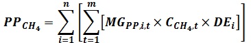
Where,
PPCH4 = Volume of methane that would have been sent to all ineligible destruction devices during the initiative reporting period. (m3)
n = Number of ineligible destruction devices
i = Ineligible destruction device
m = Number of measurement periods
t = Measurement period as set out in Table 7.1
MGPP,i,t = Volume of mine gas sent to ineligible destruction device i in measurement period t (m3)
CCH4,t = Average methane content in the mine gas, sent to an ineligible destruction device during measurement period t (m3 CH4/ m3 MG)
DEi = Default methane destruction efficiency of ineligible destruction device i, as set out in Table A.1 - The value for MGPP,i,t in Equation 6.4 includes the following mine gas only after the surface well has been mined through:
- All mine gas from the surface well sent to the ineligible destruction device during the reporting period during which the surface well was mined through; and
- All mine gas for sent from the surface well to the ineligible destruction device during reporting periods prior to the surface well being mined through.
- The value for MGPP,i,t in Equation 6.4 may be estimated by:
- Using the full capacity of the ineligible destruction device; or
- Using the calculations from the baseline monitoring period for the ineligible destruction device.
6.1.2 Calculation of Initiative Emissions from Drainage Initiatives
- Drainage Initiative emissions are actual GHG emissions that occur within the GHG Assessment Boundary as a result of the Drainage Initiative and are calculated in accordance with Equation 6.5.
- The CO2 emissions from the destruction of mine methane from a pre-mining surface well used to extract mine methane during a current reporting period, shall be calculated using Equation 6.8, and must be included even if the well has not yet been mined through.
Equation 6.5. Calculating Initiative Emissions from Drainage Initiatives

Where,
PE = Initiative emissions during the reporting period (tCO2e)
FFCO2 = Total CO2 emissions from the use of fossil fuel during the reporting period, calculated using Equation 6.6 (tCO2e)
ELCO2 = Total CO2 emissions from the use of electricity during the reporting period, calculated using Equation 6.7 (tCO2e)
DMCO2 = Total CO2 from the destruction of methane during the reporting period, calculated using Equation 6.8 (tCO2e)
UMCH4 = Methane emissions from uncombusted methane during the reporting period, calculated using Equation 6.9 (tCO2e)
Equation 6.6. Emissions from Fossil Fuels
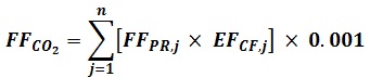
Where,
FFCO2 = Total CO2 emissions from the use of fossil fuel during the reporting period (tCO2e)
n = Number of types of fossil fuel
j = Type of fossil fuel
FFPR,j = Annual quantity of fossil fuel j used in the operation of equipment during the reporting period (volume fossil fuel)
EFCF,j = CO2 emission factor for fossil fuel j as set out in ON.20 of the QRV Guideline (kg CO2/ volume of fossil fuel)
0.001 = Conversion factor, kilograms to tonnes (tCO2/kg CO2)
Equation 6.7. Emissions from Electricity Use
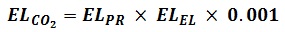
Where,
ELCO2 = Total CO2 emissions from the use of electricity during the reporting period (tCO2)
ELPR = Total electricity used for the initiative for during the reporting period (MWh)
ELEL = CO2 emission factor for electricity generation from the province in which the initiative is located as set out in the version of the NIR that is published immediately before the end of the reporting period (kg CO2/ MWh)
0.001 = Conversion factor, kilograms to tonnes (tCO2/kg CO2)
Equation 6.8. Emissions from Destruction of Captured Mine Methane
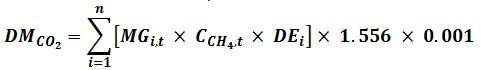
Where,
DMCO2 = Total CO2 from the destruction of methane during the reporting period (tCO2e)
n = Number of eligible destruction devices
i = Eligible destruction device
MGi,t = Volume of mine gas sent to eligible destruction device i in measurement period t (m3 MG)
CCH4,t = Average methane content in the mine gas sent to an eligible destruction device during measurement period t (m3 CH4/ m3 MG)
DEi = Default methane destruction efficiency of the eligible destruction device i, as set out in Table A.1
1.556 = CO2 emission factor from the combustion of methane (kg CO2/m3)
0.001 = Conversion factor, kilograms to tonnes (tCH4/kg CH4)
Equation 6.9. Emissions from Uncombusted Methane
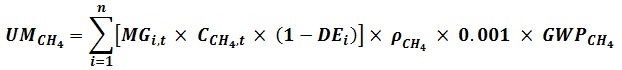
Where,
UMCH4 = Methane emissions from uncombusted methane during the reporting period (tCO2e)
n = Number of eligible destruction devices
i = Eligible destruction device
MGi,t = Volume of mine gas sent to eligible destruction device i in measurement period t (m3)
CCH4,t = Average methane content in the mine gas sent to an eligible destruction device during measurement period t (m3 CH4/m3 MG)
DEi = Default methane destruction efficiency of the eligible destruction device i, as set out in Table A.1 (kg/m3/l)
ρCH4 = Density of methane at the reference temperature, as set out in Table A.2. (kg CH4/m3)
0.001 = Conversion factor, kilograms to tonnes (tCH4/kg CH4)
GWPCH4 = Global Warming Potential of CH4, as set out in O.Reg. 143/16 (tCO2e/tCH4)
6.2 Calculation of Emission Reductions from Ventilation Air Methane Initiatives
6.2.1 Calculation of Baseline Emissions from Ventilation Air Methane Initiatives
- Baseline scenario emissions of the VAM Initiative for a reporting period shall be calculated in accordance with Equation 6.10.
Equation 6.10. Calculating Baseline Scenario Emissions
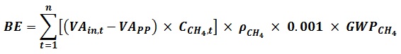
Where,
BE = Baseline scenario emissions during the reporting period (tCO2e)
n = Number of measurement periods
t = Measurement period as set out in Table 7.1
VAin,t = Volume of ventilation air sent to an eligible destruction device during time interval t (m3)
VAPP = Volume of ventilation air that would have been sent to the ineligible destruction device, during time interval t (m3)
CCH4,t = Average methane content in ventilation air sent to an eligible destruction device during time interval t (m3 CH4/m3)
ρCH4 = Density of methane at the reference temperature, as set out in Table A.2 kg CH4/m3)
0.001 = Conversion factor, kilograms to tonnes (tCH4/kg CH4)
GWPCH4 = Global Warming Potential of CH4, as set out in O.Reg. 143/16 (tCO2e/tCH4) - The value for VAPP in Equation 6.10 may be estimated by:
- Using the full capacity of the ineligible destruction device; or
- Using the calculations from the baseline monitoring period for the ineligible destruction device.
- If a mass flow meter is used to monitor gas flow instead of a volumetric flow meter, the VAin,t, VAPP and ρCH4 must be replaced by the monitored mass value in kilograms and CCH4,t must be expressed in mass percent.
6.2.2 Calculation of Initiative Emissions from Ventilation Air Methane Initiatives
- VAM Initiative emissions are actual GHG emissions that occur within the GHG Assessment Boundary calculated in accordance with 6.11.
Equation 6.11. Calculating VAM Initiative Emissions
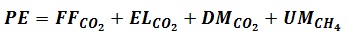
Where,
PE = Initiative emissions during the reporting period (tCO2e)
FFCO2 = Total CO2 from the use of fossil fuel during the reporting period, calculated using Equation 6.12 (tCO2e)
ELCO2 = Total CO2 emissions from the use of electricity during the reporting period, calculated using Equation 6.13 (tCO2e)
DMCO2 = Total CO2 from the destruction of methane during the reporting period, calculated using Equation 6.14 (tCO2e)
UMCH4 = Methane emissions from uncombusted methane during the reporting period, calculated using Equation 6.16 (tCO2e)Equation 6.12. Emissions from Fossil Fuels
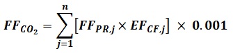
Where,
FFCO2 = Total CO2 from the use of fossil fuel during the reporting period (tCO2e)
n = Number of types of fossil fuel
j = Type of fossil fuel
FFPR,j = Annual quantity of fossil fuel j used for the operation of equipment during the reporting period (fossil fuel)
EFCF,j = CO2 emission factor for fossil fuel j as set out in ON.20 of the QRV Guideline (kg CO2/volume fossil fuel)
0.001 = Conversion factor, kilograms to tonnes (tCO2/kg CO2)Equation 6.13. Emissions from Electricity Use
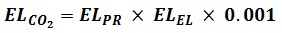
Where,
ELCO2 = Total CO2 emissions from the use of electricity reporting period (tCO2)
ELPR = Total electricity used for the initiative during the reporting period (MWh)
ELEL = CO2 emission factor for electricity generation from the province in which the initiative is located as set out in the version of the NIR that is published immediately before the end of the reporting period (kg CO2/ MWh)
0.001 = Conversion factor, kilograms to tonnes (tCO2/kg CO2)Equation 6.14. Initiative Emissions from Destruction of Captured Mine Methane

Where,
DMCO2 = Total CO2 from the destruction of methane during the reporting period (tCO2e)
VAin = Volume of ventilation air entering the destruction device during the initiative reporting period (m3)
VAout = Volume of ventilation air leaving the destruction device during the reporting period measured in accordance with Table 7.1 or calculated in accordance with Equation 6.15 (m3)
CCH4,t = Average methane content in ventilation air before entering destruction device during the reporting period (m3 CH4/m3)
Cdest,CH4 = Average methane content in ventilation air leaving the destruction device during the reporting period (m3 CH4/m3)
1.556 = CO2 emission factor from the combustion of methane (kg CO2/m3 CH4)
0.001 = Conversion factor, kilograms to tonnes (tCH4/kg CH4)Equation 6.15. Ventilation Air Leaving the Eligible Destruction Device
Where,
VAout = Volume of ventilation air leaving the eligible destruction device during the reporting period (m3)
VAin = Volume of ventilation air entering the eligible destruction device during the reporting period (m3)
CA = Volume of cooling air added after the point of metering for the volume of ventilation air sent to the eligible destruction device (VAin) (m3)Equation 6.16. Emissions from Uncombusted Methane

Where,
UMCH4 = Methane emissions from uncombusted methane during the reporting period (tCO2e)
VAout = Volume of ventilation air leaving the eligible destruction device during the reporting period, in cubic meters at standard conditions, subject to paragraph b) below (m3)
Tdest,CH4 = Average methane content in ventilation air leaving the eligible destruction device during the reporting period (m3 CH4/m3)
ρCH4 = Density of methane at the reference temperature, as set out in Table A.2. subject to paragraph b below (kg CH4/m3)
0.001 = Conversion factor, kilograms to tonnes (tCH4/kg CH4)
GWPCH4 = Global Warming Potential of methane, as set out in O.Reg. 143/16 (tCO2e/tCH4) - If a mass flow meter is used to monitor gas flow instead of a volumetric flow meter, the VAout and ρCH4 must be replaced by the monitored mass value in kilograms and Tdest,CH4 must be expressed in mass percent.
7. Data Management and Monitoring
7.1 Data Collection
- A data management system shall be implemented to collect, manage and store information related to the MMC Initiative in a way that ensures the integrity, exhaustiveness, accuracy and validity of the information.
- The data management system for the MMC Initiative shall include procedures to:
- Monitor the performance of the MMC Initiative and the operation of all MMC Initiative-related equipment, in accordance with Sections 7.2 and 7.5 this Protocol;
- Manage information, including data in respect of the baseline scenario and the initiative;
- Provide the accredited verification body access to the mine site, suppliers and where applicable, the owner or operator of any offsite destruction devices and any other information or persons that the accredited verification body may require to verify the initiative;
- Assess whether the MMC Initiative meets the eligibility criteria set out in the Regulation and this Protocol;
- Identify and record any violations of legal requirements that apply to the MMC Initiative and that may have an impact on the amount of GHG reductions, avoidances or removals; and
- Assess and record a description of the impact of each violation identified under paragraph 5.
- The data management system for the MMC Initiative shall include records required by the Regulation and this Protocol, including records of the following monitoring requirements and documents:
- All baseline scenario and MMC Initiative continuous monitoring devices shall record values every 15 minutes for Drainage Initiatives, or every 2 minutes for VAM Initiatives, except as set out in paragraph (1) below, and include the average at a minimum frequency of daily.
- Initiatives with continuous CH4 analyzers may record values at frequencies other than every 15 minutes in accordance with the data acquisition system, and include the average at a minimum frequency of daily.
- All other baseline scenario monitoring devices shall record one measured value per day on the day the measurement was made
- All other monitoring devices shall record values and average those values at the frequencies set out in Section 7.5 this Protocol.
- The role and qualifications of the person responsible for each monitoring activity.
- Documentation of the engineering design and flow characteristics of the MMC system including at a minimum a detailed diagram of the MMC system and destruction devices showing the location of existing and planned wells and boreholes and the placement of all measurement instruments and equipment that affect included SSRs.
- All baseline scenario and MMC Initiative continuous monitoring devices shall record values every 15 minutes for Drainage Initiatives, or every 2 minutes for VAM Initiatives, except as set out in paragraph (1) below, and include the average at a minimum frequency of daily.
7.2 Monitoring Requirements
7.2.1 General
- Procedures shall be established and followed to accurately assess whether the MMC Initiative meets the applicable eligibility criteria set out in Section 4 of this Protocol.
- All MMC Initiative-related equipment shall be operated in a manner consistent with the manufacturer’s specifications and in accordance with Section 7 this Protocol and the performance of the initiative shall be monitored in accordance with Section 7.5 this Protocol.
- Electricity data may be measured using an on-site meter or determined using electricity purchasing records.
- Fossil fuel use may be determined using monthly fossil fuel purchasing records.
7.2.2 Flow Meters
- The MMC Initiative shall be monitored with equipment that directly meters the flow of mine gas delivered to each eligible and ineligible destruction device, measured continuously.
- A single meter may be used for multiple, destruction devices if:
- The destruction devices are identical and have identical destruction efficiencies; or
- The destruction devices are not identical and the efficiency of the least efficient destruction device is used.
- A single meter may be used for multiple, destruction devices if:
- The temperature and pressure of the mine gas shall be measured separately and continuously.
- All flow data collected shall be corrected to reference pressure and reference conditions as follows:
- The correction shall be made using:
- The volume from the flow meter when the meter corrects for temperature and pressure; or
- Equation 7.1 to calculate the corrected volume, when the condition in i is not met.
- The reference pressure shall be 1 atm (101.325 kPa).
- The reference temperature may be chosen from Table A.2, based on any applicable reference temperature standard of the jurisdiction in which the initiative is located and shall be applied consistently for data adjustment during the reporting period.
- The correction shall be made using:
- The density of methane at the reference temperature that is set out in Table A.2.
Equation 7.1. Adjusting Mine Gas Flow for Temperature and Pressure
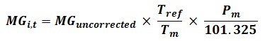
Where,
MGi,t = Corrected volume of mine gas sent to eligible destruction device i in time interval t (m3)
MGuncorrected = Uncorrected volume of mine gas sent to destruction device i in time interval t (m3)
Pm = Measured pressure of the mine gas for the given time interval (kPa)
Tref = Reference temperature of the mine gas for the initiative (K)
Tm = Measured temperature of the mine gas for the given time interval (K)
101.325 = Reference pressure of the mine gas for the initiative (kPa)
7.2.3 Methane Analyzers
- Each destruction device of the MMC system shall be monitored with equipment that directly calculates the per cent of methane in the mine gas and the measurements on which this calculation is based shall be made using:
- Measurements from a continuous methane analyzer (This is the preferred equipment); or
- Where a continuous methane analyzer is not used, a non-continuous methane measurement that:
- Measures at a frequency of at least weekly for no more than four consecutive weeks for Drainage Initiatives;
- Has an uncertainty associated with these measurements that is accounted for by applying a 10% discount factor to the total quantity of mine methane collected and destroyed in Equation 6.2; and
- Uses one of the following devices:
- A calibrated, portable methane analyzer; or
- A device that collects mine gas samples at least weekly into a common container which is then analyzed at least monthly by an off-site laboratory that provides an average methane concentration of the sample.
7.2.4 Operational Status of Eligible Destruction Devices
- The operational status of the MMC system and each eligible destruction device shall be monitored with measurements recorded at least hourly unless:
- The eligible destruction device is not operating;
- The engineering design of the MMC system is such that mine gas is not released when the eligible destruction device is not operating; and
- Such design elements are functioning properly and there is documented evidence to support this.
- If the eligible destruction device is a flare, it must achieve thermocouple readings above 260°C, or the regulatory standard for the relevant jurisdiction, whichever is higher.
- When a single flow meter is used for multiple, identical eligible destruction devices per Subsection 7.2.2(a)1 of this Protocol, the operational status of each destruction device shall be monitored separately unless the design of the eligible destruction device is such that mine methane is not released when it is not operating and there is documented evidence to support this.
- Where mine methane is delivered from the mine site to a destruction device at another facility via a direct use pipeline, reasonable efforts shall be made to obtain data demonstrating the type of destruction device used at the other facility and the operational status of that device.
- Where mine gas is delivered from the mine site to a destruction device via injection into a natural gas transmission pipeline, reasonable efforts shall be made to obtain data demonstrating the operational status of the natural gas transmission pipeline.
- If it is not possible to obtain the dataset out in paragraphs (d) and (e), reasonable evidence must be obtained demonstrating that there has been no significant release of mine gas between when it was collected and when it was destroyed and that the appropriate destruction efficiency value, set out in Table A.1, has been applied. Evidence may include:
- A signed attestation from the owner or operator of the pipeline that no significant release of mine gas occurred during the reporting period; and
- Supporting documents and records such as electrical output data, engineering designs and safety features that demonstrate mine gas is not released when the destruction device is not operating or that the flow of mine gas off-site can be shut off in the event of an emergency or any other supporting documents.
- If an initiative uses a single flow meter to monitor multiple destruction devices and there are any periods when not all destruction devices downstream of the flow meter are operational, mine methane destruction at the operational destruction devices is not eligible unless:
- The destruction efficiency of the least efficient operational destruction device is used as the destruction efficiency for all of the operational destruction devices;
- The engineering design of all the destruction devices is such that mine gas is not released when the eligible destruction device is not operating and that such design elements are functioning properly and there is documented evidence to support this; and
- There is documented evidence to demonstrate that the operational destruction devices have the capacity to destroy all of the mine gas coming through the flow meter.
7.2.5 Arrangement of Devices in the LFG Collection System
- The number and arrangement of flow meters shall be sufficient to track the mine gas flow to each eligible and ineligible destruction device.
- The flow meter shall be placed such that it measures the volume of mine gas delivered to each eligible and ineligible destruction device prior to the introduction of any supplemental fuels.
- The methane analyzer shall be placed such that it measures methane concentration of the mine gas delivered to an eligible or ineligible destruction device prior to the introduction of any supplemental fuel.
- A moisture-removing component may separate the methane analyzer and the flow meter where the methane analyzer is placed before the moisture-removing component (wet basis), and the flow meter is placed after that component (dry basis).
- A moisture-removing component shall not separate the methane analyzer and flow meter in any other configuration other than as described in paragraph (d) above.
- A moisture-removing component shall not separate the flow meter and the temperature and
7.2.6 Baseline Scenario Monitoring Period
- If the value for MGPP,i,t and VAPP is determined using the baseline monitoring period for the ineligible destruction device then both of the following rules apply:
- Monitoring of all ineligible destruction devices shall be done over a period of at least 3 consecutive months prior to the start date (“baseline scenario monitoring period”) and must follow the same monitoring requirements as outlined in Section 7 of this Protocol.
- The baseline scenario monitoring period cannot include a period where the volume of mine gas flow that is measured is decreased by activities related to the start up or testing period the initiative (e.g., pressure changes from the installation of wells, etc.).
7.3 Instrument Quality Assurance and Quality Control (QA/QC)
- Mine gas flow meters and methane analyzers shall be:
- Located and installed for the intended use, in accordance with manufacturer specifications;
- Calibrated at the time of installation;
- Cleaned and inspected in accordance with the manufacturer’s specifications;
- Not later than 2 months before the end of a reporting period:
- Checked for accuracy by a qualified and independent person, either using a portable instrument, such as a pitot tube, or by following the manufacturer’s specifications, and the percentage drift recorded; or
- Calibrated by the manufacturer, or by a third party certified for that purpose by the manufacturer; and;
- Calibrated by the manufacturer, or by a third-party certified for that purpose by the manufacturer, in accordance with the manufacturer’s specified frequency or every 5 years, whichever is more frequent.
- Flow meters and methane analyzers that are not portable devices but are installed temporarily shall be calibrated at the time of installation.
- The mine gas flow meter and methane analyzer calibration accuracy must show that these monitoring devices provide a reading of volumetric flow and methane concentration that is within a ± 5% accuracy threshold.
- If the device shows a shift outside the ± 5% accuracy threshold the following rules apply:
- Appropriate corrective action(s) shall be taken, such as cleaning or adjusting the sensor in accordance with the manufacturer’s specification.
- The device shall be rechecked for measurement accuracy in accordance with Subsection 7.3(a)4.i after the corrective action.
- If the device is still out of the ± 5% accuracy threshold, the device shall be calibrated by the manufacturer or by a third party certified for that purpose by the manufacturer.
- For the entire period from the last time the monitoring device showed a reading within the ± 5% accuracy threshold until such time as the monitoring device shows a return to the accuracy threshold all the data from the monitoring device shall be corrected according to the following rules:
- When the inaccuracy of the device indicates an under-reporting of flow rate or methane concentration, the measured values taken by the inaccurate device, without correction shall be used; or
- When the inaccuracy of the device indicates an over-reporting of flow rates or methane concentration, the measured values of the inaccurate device shall be corrected by the percentage that the device was out of the ± 5% accuracy threshold.
- If a portable methane analyzer is used to check accuracy, it shall be:
- Maintained in accordance with the manufacturer’s specifications; and
- Calibrated by the manufacturer or by a third party certified for that purpose by the manufacturer for that purpose in accordance with the manufacturer’s specified frequency or annually, whichever is more frequent.
- Equipment used for monitoring parameters other than mine gas flow and methane concentration (e.g., standalone temperature sensors, flare thermocouples, etc.) shall be installed, maintained and calibrated in accordance with the manufacturer’s specifications.
7.4 Missing Data
- Missing data from a monitoring device may only be replaced using the methodology in Appendix B. The methodology in Appendix B may only be used if the following two conditions are met:
- The operational status of the eligible destruction device can be demonstrated in accordance with the requirements of Section 7.2.4 of this Protocol; and
- The operational status and proper functioning of the device monitoring the eligible destruction device can be demonstrated in accordance with the requirements of Section 7.3 of this Protocol.
- If the methodology in Appendix B is being used to replace missing data from a flow meter or methane analyzer then data may only be replaced in accordance with the following rules:
- Mine gas flow rate may be replaced when methane concentration is not missing and where a continuous methane analyzer was used to measure methane concentration and the methane concentration was consistent with normal operations;
- Methane concentration may be replaced when flow meter data is not missing and a flow meter demonstrates that the mine gas flow rate was consistent with normal operations; or
- Where both methane concentration and mine gas flow rate are missing, data may only be replaced for electric generators and natural gas injection and only in accordance with paragraphs (c) and (d) below.
- For initiatives that destroy mine gas in an eligible destruction device that also generates electricity, the missing data may be replaced for periods of up to 6 months after the applicable version of the Protocol comes into effect by using Equation B.1, in Appendix B if the electrical output for the period of missing data has been monitored.
- For initiatives that inject mine gas into a natural gas transmission pipeline, the missing data for periods up to 6 months after the applicable version of the Protocol came into effect may be replaced through either:
- The use of the volumetric methane data as reported by the flow meter at the point of pipeline injection, or,
- By using Equation B.2 in Appendix B if the data is reported in units of energy, but only if:
- The volume of mine gas is continuously monitored throughout the period of the data gap;
- Any supplemental natural gas mixed with the mine methane prior to the custody transfer meter is monitored throughout the period of the data gap and subtracted from the volume in i; and
- Any other fuel sent to the pipeline, is directly monitored throughout the period of the data gap and subtracted from the volume in i.
7.5 Monitoring Parameters
- Table 7.1 sets out the monitoring parameters required to be used in the calculation of baseline scenario and initiative emissions
| Eq. # | Parameter | Description | Data Unit | Calculated (c) Measured (m) Reference (r) Operating Records (o) |
Measurement Frequency | References |
|---|---|---|---|---|---|---|
| N/A | N/A | Operating status of destruction device | Unit determined per destruction device | m | Hourly | N/A |
| Equation 6.2 | Qi | Total quantity of methane sent to eligible destruction device i during the reporting period | m3 | c | Every reporting period | Calculated using Equation 6.3 |
| Equation 6.2 | PPCH4 | Volume of methane that would have been sent to all ineligible destruction devices during the reporting period | m3 | c | Every reporting period | Calculated using Equation 6.4 |
| Equation 6.2 Equation 6.9 Equation 6.10 Equation 6.16 |
GWPCH4 | Global Warming Potential for CH4 | tCO2e/tCH4 | r | Every reporting period | As set out in O.Reg. 143/16 |
| Equation 6.3 Equation 6.8 Equation 6.9 |
MGi,t | Corrected volume of mine gas sent to eligible destruction device i, in measurement period t | m3 | m/c | Continuously | Measured for cases where the meter internally corrects to standard conditions, otherwise calculated using Equation 7.1 |
| Equation 6.3 Equation 6.4 Equation 6.8 Equation 6.9 Equation 7.1 |
t | Measurement period | Day, hour, or minute | m | Continuously or daily | N/A |
| Equation 6.3 Equation 6.4 Equation 6.8 Equation 6.9 Equation 6.10 Equation 6.14 |
CCH4,t | Average methane content in the mine gas or ventilation air for the measurement period t | m3 CH4/m3 MG | m | Continuously | N/A |
| Equation 6.4 | MGPP,i,t | Volume of mine gas sent to ineligible destruction device i, in time interval t | m3 | m/c | Every reporting period | Estimated at start of the initiative |
| Equation 6.6 Equation 6.12 |
FFPR,j | Annual quantity of fossil fuel j used in the operation of equipment during the reporting period | kg (solid) m3 (gas) L (liquid) |
c | Every reporting period | N/A |
| Equation 6.7 Equation 6.13 |
ELPR | Total electricity used for the initiative during the reporting period | Megawatt-hour | m/c | Every reporting period | N/A |
| Equation 6.10 Equation 6.15 |
VAin,t | Volume of ventilation air sent to the eligible destruction device | m3 | m/c | Continuously | N/A |
| Equation 6.10 | VAPP | Volume of ventilation air sent to ineligible destruction device | m3 | m/c | Every reporting period | N/A |
| Equation 6.14 | VAout | Volume of ventilation air leaving the destruction device | m3 | m/c | Continuously | Calculated using Equation 6.15 |
| Equation 6.14 | CDest,CH4 | Average methane content in ventilation air leaving the destruction device | m3 CH4/m3 | m | Continuously | N/A |
| Equation 6.15 | CA | Volume of cooling air added after the point of metering for VAin | m3 | m/c | Continuously | N/A |
| Equation 6.16 | Tdest,CH4 | Average methane content in ventilation air leaving the destruction device during the reporting period | m3 CH4/m3 | m | Continuous and recorded at least every 2 minutes | N/A |
| Equation 7.1 | MGuncorrected | Uncorrected volume of mine gas sent to destruction device i, in time interval t | m3 | m | Continuously | N/A |
| Equation 7.1 | Tm | Mine gas or ventilation air temperature | K | m | Continuously | N/A |
| Equation 7.1 | Pm | Mine gas or ventilation air pressure | kPa | m | Continuously | N/A |
8. Reversals
8.1 Reversals Listed for the Purposes of s. 20(1) paragraph 1
- There are no reversals listed in this Protocol for the purpose of s. 20(1) paragraph 1 of O.Reg. 539/17.
8.2 Errors, Omissions or Misstatements
- In the event that an error, omission or misstatement is discovered after Ontario offset credits have been created and issued for a reporting period, the Sponsor shall determine the total amount of the reversal by:
- Using this Protocol to re-calculate the corrected value of the GHG emission reductions from the MMC Initiative during the reporting period for each initiative report affected by the reversal.
- Calculating the total reversal of GHG emission reductions from the MMC Initiative using Equation 8.1
Equation 8.1. Calculating GHG Emission Reductions Reversed
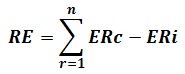
Where,
RE = GHG emission reductions reversed (tCO2e)
n = Total number of initiative reports affected by the reversal
r = Initiative reports affected by the reversal
ERc = Corrected GHG emission reductions from the initiative during the reporting period calculated in accordance with Subsection 8.2(a)(1) (tCO2e)
ERi = Initially reported GHG emission reductions from the initiative during the reporting period (tCO2e)
9. Reporting
- The following information shall be set out in an initiative report or a reversal report in addition to the information required by the Regulation.
9.1 Initiative Report
9.1.1 Eligibility Criteria Information
- A description of the type of mine where the MMC Initiative is located.
- A description of the location of the mine.
9.1.2 Monitoring Information
- Identify all eligible and ineligible destruction devices within the initiative GHG Assessment Boundary as set out in Section 5 of this Protocol.
- A description of how the initiative was monitored, including all the following:
- A statement of whether the monitoring performed meets the requirements set out in Section 7 of this Protocol.
- A statement of whether all gas flow meters and CH4 analyzers adhered to the instrument QA/QC requirements set out in Section 7.3 of this Protocol.
- Where applicable, an identification of any deviations from the requirements set out in Section 7 of this Protocol and a description of whether these deviations should be considered material.
- Calibration certificates or verification reports on the calibration accuracy, from either the manufacturer or a qualified third-party certified by the manufacturer for each piece of monitoring equipment.
- Where applicable, identification of instances where any piece of equipment failed a calibration and a description of how the data from that equipment was corrected in accordance with Section 7.3, including any calculations used.
- Where applicable, identification of instances where the data substitution methodology set out in Section 7.4 of this Protocol was applied, and a description as to how the data was substituted including any calculations used.
- Identification of the measurement frequency used for each monitoring parameter, where multiple frequencies may be used in accordance with Section 7.5 of this Protocol.
9.1.3 Quantification Information
- All calculations set out in Section 6, including any supporting calculations set out in Section 7 of this Protocol that were used.
- The reference temperature and density used.
- Identification of any source test data, if used in place of the default destruction efficiencies, as set out in Appendix A.
9.2 Reversal Report
9.2.1 General
- Information about the circumstances and causes of the reversal including the number of reporting periods affected.
- For each initiative report that was affected by the reversal, all information that has changed as a result of the reversal and a description of those changes.
- In the case of an error, omission or misstatement reversal, a description of the corrective actions taken to address the circumstances and causes of the reversal.
- Supporting documentation for each of the items in paragraphs (a) through (c) above.
9.2.2 Quantification Information
- All calculations set out in Section 8 of this Protocol, including supporting calculations set out in Section 6 and Section 7 of this Protocol, that were used to determine the amount of the reversal.
- Supporting documentation related to the calculations.
10. Record Keeping
- The following records and documents shall be kept in addition to the records that are required to be kept under the Regulation:
- The information and data required under the monitoring requirements in Section 7 of this Protocol, including all GHG calculations and related data inputs.
- Information on each eligible and if applicable ineligible flow meter, methane analyzer and destruction device used, including type, model number, serial number and manufacturer’s maintenance and calibration procedures.
- Maintenance documents and records relating to collection, destruction and monitoring systems including:
- For each mine gas flow meter and methane analyzers, records and documents relating to all instrument QA/QC activities.
- For a portable analyzer, time and place where measurements are taken and, for each measurement, the methane concentration in the mine gas.
- The calibration date, time and results for methane analyzers and flow meters, and the corrective measures applied if a piece of equipment failed to meet the requirements of this Protocol:
- Flow meter calibrations shall be documented to show that the meter was calibrated to a range of flow rates corresponding to the flow rates expected at the mine site.
- Methane analyzer calibrations shall be documented to show that the calibration was carried out to a range of temperature and pressure conditions corresponding to the range of conditions measured at the mine site.
- Operating records showing:
- Annual coal production;
- The mining method employed (required for underground mines only), e.g., room and pillar, longwall;
- The year of initial mine operation; and
- The scheduled year of mine closure, if known;
- All documentation related to permits related to the coal mine (e.g., mining permits, air quality, water quality, land use, system construction, etc.), as well as documentation related to any regulatory compliance inquiries, warnings, or violations.
- All documentation related to any violations of legal requirements that apply to the initiative or that may have an impact on the amount of GHG reductions, avoidances or removals.
Appendix A: Parameters for Quantification
A.1 Methane Destruction Efficiency
- The appropriate methane destruction efficiency shall be selected from Table A.1 below.
| Eligible Destruction Device | Efficiency |
|---|---|
| Open Flare | 0.96 |
| Enclosed Flare | 0.995 |
| Internal Combustion Engine | 0.936 |
| Boiler | 0.98 |
| Microturbine or Large Gas Turbine | 0.995 |
| Boiler Following Upgrade and Injection into a Pipeline | 0.96 |
| CH4 Liquefaction Unit | 0.95 |
| Injection into Natural Gas Transmission Pipeline | 0.98 |
| Direct Use Pipeline (End Use Other than Boiler) | Per the appropriate end use device |
| For VAM Initiatives only: | n/a |
| Thermal oxidizers with or without catalysts | n/a |
| Volatile organic compound concentrators | n/a |
| Carbureted gas turbines | n/a |
| Lean-fueled turbines with catalytic combustors that compress the air/methane mixture and then combust it in a catalytic combustor | n/a |
| Hybrid coal- and ventilation air-fueled gas turbine technology | n/a |
| Lean-fueled catalytic microturbine technology | n/a |
| Combustion air for commercial engine and turbine technologies or a coal-fired steam power plant | n/a |
A.2 Methane Density
- The appropriate methane density at the reference temperature shall be selected from Table A.2 below.
| Reference Pressure kPa | Reference Pressure atm | Reference Temperature °C | Reference Temperature K | Density of CH4 (kg/m3) |
|---|---|---|---|---|
| 101.325 | 1 | 0 | 273.15 | 0.717 |
| 101.325 | 1 | 5 | 278.15 | 0.704 |
| 101.325 | 1 | 10 | 283.15 | 0.692 |
| 101.325 | 1 | 15 | 288.15 | 0.680 |
| 101.325 | 1 | 20 | 293.15 | 0.668 |
| 101.325 | 1 | 25 | 298.15 | 0.657 |
Appendix B: Missing Data – Substitution Methods
- The appropriate substitution method to replace data shall be selected from Table B.1 below.
| Missing Data Period | Substitution Method |
|---|---|
| Less than 6 hours | Use the average of the 4 hours immediately before and following the missing data period |
| 6 to less than 24 hours | Use the 90% upper or lower confidence limit of the 72 hours prior to and after the missing data period, whichever results in greater conservativeness |
| 1 to 7 days | Use the 95% upper or lower confidence limit of the 72 hours prior to and after the missing data period, whichever results in greater conservativeness |
| More than 7 days | No data may be replaced and no reduction may be credited, except for initiatives that destroy MG in a device that generates electricity or via pipeline injection, as set out in Subsections 7.4 (c) and (d) respectively. |
B.1 Calculations
Equation B.1. Calculating Estimated Volume of CH4 Destroyed in Electricity Generators
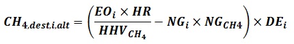
Where,
CH4,dest,i,alt = Net quantity of methane destroyed by electricity generating device i during the period of missing data (m3 CH4)
EOi = Total electrical output of device i during the period of missing data (kWh)
HRi = Heat rate of destruction device i, as determined through the most recent source testing event. If no source test data are available, the heat rate specified by the manufacturer shall be used (GJ/kWh)
HHVCH4 = Higher heating value of the methane portion of the MG. 0.0359 (GJ/m3 CH4)
NGi = Total quantity of supplemental natural gas sent to device i during the period of missing data (m3 NG)
NGCH4 = Average ratio of methane to NG in the supplemental natural gas, as set out in the suppliers specifications(m3 CH4/m3 NG)
DEi = Methane destruction efficiency of device i, as set out in Table A.1 (fraction)
Equation B.2. Calculating Estimated Volume of Methane Destroyed by Pipeline Injection
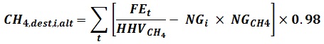
Where,
CH4,dest,i,alt = Net quantity of methane destroyed by pipeline injection i during the period of missing data (m3 CH4)
t = Measurement period
FEt = Fuel energy delivered during measurement period t, as reported in gas delivery data (GJ)
HHVCH4 = Higher heating value of the methane portion of the MG. 0.0359 (GJ/m3 CH4)
NGi = Total quantity of supplemental natural gas sent to device i during the period of missing data (m3 NG)
NGCH4 = Average ratio of methane to NG in the supplemental natural gas, as set out in the suppliers specifications (m3 CH4/m3 NG)
0.98 = Methane destruction efficiency of pipeline injection, as set out in Table A.1 (fraction)
Footnotes
- footnote[1] Back to paragraph The calculation of annual receipt of waste includes all materials received, with the exception of clean soils and manufactured products.
- footnote[2] Back to paragraph The quantity of waste in place may be determined either by: 1) the filled volume of the landfill (in m3) at the time of initiative registration, multiplied by the density (0.75 t/m3) and the decomposable % (0.70); or 2) the annual receipt of waste since the landfill opened.
- footnote[3] Back to paragraph The calculation of annual receipt of waste includes all materials received, with the exception of clean soils and manufactured products.
- footnote[4] Back to paragraph The calculation of annual receipt of waste includes all materials received, with the exception of clean soils and manufactured products.
- footnote[5] Back to paragraph The quantity of waste in place may be determined either by: 1) the filled volume of the landfill (in m3) at the time of initiative registration, multiplied by the density (0.75 t/m3) and the decomposable % (0.70); or 2) the annual receipt of waste since the landfill opened.
- footnote[6] Back to paragraph For the purpose of using Equation 6.3 to determine BDdiscount, the quantity of landfill gas would be only that which is being metered from the corresponding cell or waste mass in which the ineligible devices had operated, and not necessarily all of the landfill gas being destroyed by the destruction system.
- footnote[7] Back to paragraph Lemmon, E.W., Huber, M.L., & McLinden, M.O. (2013). NIST Standard Reference Database 23: Reference Fluid Thermodynamic and Transport Properties-REFPROP. Version 9.1. National Institute of Standards and Technology, Standard Reference Data Program, Gaithersburg.
- footnote[8] Back to paragraph Setzmann, U., & Wagner, W. (1991). A New Equation of State and Tables of Thermodynamic Properties for Methane Covering the Range from the Melting Line to 625 K at Pressures up to 1000 MPa. J. Phys. Chem. Ref. Data, 20(6):1061-1151.
- footnote[9] Back to paragraph Based on the most recent list of approved destruction technologies provided by the Ozone Secretariat of the United Nations Environment Programme.
- footnote[10] Back to paragraph TEAP. (2002). Report of the Task Force on Destruction Technologies. Volume 3B.
- footnote[11] Back to paragraph TEAP. (2006). Code of Good Housekeeping. Handbook for the Montreal Protocol on Substances that Deplete the Ozone Layer, 7th Edition.
- footnote[12] Back to paragraph Lemmon, E.W., Huber, M.L., & McLinden, M.O. (2013). NIST Standard Reference Database 23: Reference Fluid Thermodynamic and Transport Properties-REFPROP, Version 9.1, National Institute of Standards and Technology, Standard Reference Data Program, Gaithersburg.
- footnote[13] Back to paragraph Setzmann, U., & Wagner, W. (1991). A New Equation of State and Tables of Thermodynamic Properties for Methane Covering the Range from the Melting Line to 625 K at Pressures up to 1000 MPa. J. Phys. Chem. Ref. Data, 20(6):1061-1151.