Technical Bulletin - Wells Regulation - Well Abandonment - How to Plug and Seal a Test Hole or Dewatering Well
The purpose of this technical bulletin is to summarize the information on abandonment requirements for a test hole or dewatering well found in the Test Holes and Dewatering Wells – Requirements and Best Management Practices manual published by the Ministry of the Environment, April 2014.
April 2014
This technical bulletin is one in a series of seventeen
- summarize the information found in the Test Holes and Dewatering Wells – Requirements and Best Management Practices manual published by the Ministry of the Environment, April 2014 (hereon in referred to as the “Manual”) regarding abandonment of test holes and dewatering, and
- present abandonment requirements for a test hole or dewatering well found in Regulation 903 (Wells Regulation), as amended, made under the Ontario Water Resources Act.
To determine when a test hole or dewatering well is required to be abandoned, well owners should consult the Wells Regulation . The technical bulletin titled Wells Regulation – Well Abandonment: When to Plug and Seal a Test Hole or Dewatering Well will provide useful information and an overview of the legal requirements.
The Person Abandoning the Well
In the case of a test hole or dewatering well that must be immediately abandoned, the person abandoning the well is one of the following:
- the person who has discontinued the construction of a new well prior to the completion of its structural stage
- the well purchaser of a new well that is dry
- the well owner of a well that:
- is not in use or being maintained for future use as a well,
- is producing water that is mineralized or not potable (not applicable to test holes or dewatering wells),
- contains natural gas or other gas,
- permits the movement of materials including natural gas and contaminants and the movement may impair the quality of the waters, or
- is constructed in contravention of the Wells Regulation requirements for location, methods, materials or standards and measures taken to rectify the problem have failed.
Abandonment of a test hole or dewatering well is not considered well construction. As a result, licensing requirements for the construction of a well do not apply to well abandonment and the obligations for abandonment are placed on the person abandoning the well, often the well owner.
For the purposes of the Wells Regulation requirements the person who works at the abandonment of a test hole or dewatering well is not considered the person abandoning the well.
Obligation to Retain a Licensed Well Contractor
Unless exempted by the Wells Regulation, the person abandoning the well, often the well owner, must do the following:
- retain the services of a licensed well contractor, and
- ensure the contract with the well contractor contains a provision that the well technician who will do the abandonment work, is licensed to construct the same type of well as the one to be abandoned.
Obligation to Retain a Licensed Well Contractor Exemption
The person abandoning the well is exempt from the above requirements if the person who works at the abandonment of the well is:
- the owner of the land or is a member of the owner’s household,
- working without remuneration (e.g., not being paid) for another person on land owned by the other person or on land owned by a member of the other person’s household, or
- a person who holds a Class 1 well technician licence (drilling).
Also, the person abandoning the well is exempt from the requirements in the “Obligation to Retain a Licensed Well Contractor” section if the person who works at the abandonment of the well uses a method that does not use powered equipment and is:
- a holder of a class 5 well technician licence or
- an experienced Professional Engineer, Professional Geoscientist, or professional registered under the Ontario Association of Certified Engineering Technicians and Technologists.
Considerations before Starting to Plug and Seal a Well
An initial factor to consider is who will be abandoning (plugging and sealing) the test hole or dewatering well. Regardless of who abandons the well, the requirements of the Wells Regulation must always be met.
If a well owner is a corporation or municipality, the well owner must retain the services of a licensed well contractor who employs properly licensed well technicians to work on the well abandonment, unless exempt. In some cases, the corporation or municipality can use a person who holds a Class 1 well technician (drilling) licence to abandon a test hole or dewatering well. Also, the corporation or municipality can use a person described in the list below to abandon the test hole or dewatering well if the person uses non-powered equipment in the abandonment operation:
- a licensed Professional Engineer including a person holding a limited or temporary licence,
- a Professional Geoscientist who is a practicing, temporary or limited member or
- a professional registered as a certified technician, certified engineering technician, applied science technologist or certified engineering technologist (CET) with the Ontario Association of Certified Engineering Technicians and Technologists.
An individual land owner or his/her family members can abandon any well situated on his/her own property without a well technician licence. Also, other individuals can abandon a well without a well technician licence for the individual land owner as long as no form of compensation is made.
Although the Ontario Water Resources Act and the Wells Regulation allow an individual land owner to abandon his/her own well(s) without a licence, the equipment, materials and expertise needed to comply with the requirements under the Wells Regulation can exceed the average land owner’s abilities and resources. A well owner needs to understand how to measure water levels, well depths and be able to calculate volumes of well water, chemical mixtures and material mixtures. For instance, if an individual land owner cannot properly calculate and mix chemicals, does not have the necessary equipment or cannot employ proper safety procedures, the requirements of the Wells Regulation will not likely be met. An improperly abandoned well could pose a safety or environmental hazard and the well owner may be subject to compliance or enforcement actions.
Because of the need for specialized equipment and technical skill, which are may be beyond the capabilities of an individual well owner, as a best management practice, it is important that wells with one or more complicating factors be plugged by a licensed well contractor who employs licensed well technicians. It may also be advisable that Professional Geoscientists or Professional Engineers be retained. Complicating factors include:
- Test holes or dewatering wells with well water that may be impacted by on or off-site contaminants (e.g., gasoline, fuel oil, pesticides or agricultural activities)
- Test holes near municipal well fields
- Freely flowing artesian test holes or dewatering wells where groundwater is discharging from the well at or close to the ground surface
- Flowing, heaving and/or running formations (e.g., sands or gravels) are encountered
- Underground crevices in karstic formations
- Test holes or dewatering wells greater than 9 m (30 ft.) deep
- Test holes or dewatering wells where surface water runoff, insects or other vermin are entering the well through the well casing
- Test holes or dewatering wells which produce poisonous or explosive gas, salty water or sulphate rich water
- Test holes or dewatering wells where the casing has collapsed or the casing is difficult or not reasonably possible to remove without proper equipment
- Areas with difficult access or access requiring specialized equipment
- Unusually heavy components associated with the test hole or dewatering well
- Nested test holes with multiple casings and layers of bentonite and filter pack materials (i.e., nested multiple test hole with seals)
- Test holes or dewatering wells where the pumping equipment is difficult or not reasonably possible to remove
- Test holes or dewatering wells located in residential, agricultural, commercial or industrial buildings (occupied or vacant)
- Test holes or dewatering wells located in close proximity to other wells in operation
- Test holes or dewatering wells located in close proximity to surface water
- Improperly abandoned wells (e.g., plugged with logs or other materials)
There may be additional conditions, other than the above list, that make it advisable for the test hole or dewatering well be plugged by licensed professionals.
For further information, licensing requirements are detailed in Chapter 4 of the Manual: Well Contractors & Well Technicians – Licences, Responsibilities & Exemptions. Contact numbers for the Ministry are also listed in the Resources section of the Manual.
Reviewing Records and Conducting Site Assessment
Persons plugging test holes and dewatering wells can use well record information along with a site assessment of the well to determine the method and materials needed before commencing to plug and seal a well.
To obtain relevant information on the test hole or dewatering well to be abandoned, a person should consider if there are any historical records of the well.
For example, a well contractor may have completed a well record and log for the original construction of the well. A copy of the original well record may be available from the:
- current or previous land owner,
- original well contractor, or
- Ministry of the Environment.
In some cases an original well record may not be available for the test hole or dewatering well. For example, some test holes or dewatering wells that have a life span of less than 30 days may not have a well record filed with the Ministry or the well owner.
Another relevant source of information is hydrogeological reports. Hydrogeological reports can be prepared as a result of various activities including:
- phase 2 environmental site assessments,
- work related to the delineation clean-up, monitoring and clean-up of contaminants, and
- hydrogeological investigations for water supplies.
An assessment of a test hole or dewatering well should be conducted prior to plugging and sealing it. The assessment should include the following factors:
- the well depth,
- the water level,
- the geochemistry of the water in the well,
- the pumping or other equipment in or around the well,
- the structure of the well, and
- the geological formations around the well.
The use of video technology by trained professionals should be included in deep wells to visually confirm the well’s characteristics and current conditions.
How to Abandon a Test Hole or Dewatering Well – Nine (9) Steps
The person abandoning the well must ensure the following nine (9) steps are taken in this sequence, unless otherwise specified:
- If the well has a well tag, it must be removed and returned to the Director within 30 days of its removal.
- If the well casing or well screen has collapsed, reasonable efforts must be made to remove the well screen or well casing. All other equipment and debris in the well must be removed.
The well, including any annular space must be plugged in the following manner:
For any Well:
Abandonment barrier material must be placed continuously from the bottom of the well upward to approximately 2 m (6.6 ft.) below the ground surface. This does not prevent the placement of clean, washed sand or gravel adjacent to water producing zones or bedrock fractures to minimize the loss of abandonment barrier (sealant) material.
The abandonment barrier must be placed in a manner that prevents any movement of water, natural gas, contaminants or other material between subsurface formations (which include aquifers) or between a subsurface formation and the top of the abandonment barrier material.
Alternative Method for Wells with a Diameter > 65.0 cm (2.1 ft.):
A continuous column of abandonment barrier must be placed up to approximately 2 m (6.6 ft.) below the ground surface as follows:
- Clean sand or pea gravel must be placed from the bottom of the well to the top of the deepest water producing zone or the top of the well screen, whichever is deeper
- At least 0.1 m (4 inches) of bentonite chips or pellets must be placed over the sand or pea gravel
- If the water level is below, or can be drawn down to the top of the bentonite chips or pellets:
- it must be drawn down to the top of the bentonite chips or pellets,
- at least 0.3 m (1 foot) of a bentonite slurry that consists of clean water and at least 20% bentonite solids and that is compatible with the quality of the water found in the well must be placed over the bentonite chips or pellets, and
- clean gravel, sand, silt or clay must be dropped over the bentonite slurry to fill the remainder of the well, while maintaining at least 0.3 m of the bentonite slurry above the rising accumulation of gravel, sand, silt or clay.
- If the water level cannot be drawn down to the top of the bentonite chips or pellets, the remainder of the well must be filled to approximately 2 m (6.6 ft.) below the ground surface with an abandonment barrier, which may be interspersed (layered) with clean sand or pea gravel placed in each water producing zone of the well.
The sealing materials that are selected and placed must provide the appropriate structural strength to support the weight of persons and vehicles that may move over the area after it is filled.
- After or during the placement of the abandonment barrier, the well casing or well screen must be removed, if reasonably possible. During the removal of the well screen or well casing, the bottom of the casing must be immersed in the rising accumulation of the abandonment barrier material until the required level has been reached.
- If all of the casing and well screen cannot be reasonably removed as above, then at least 2 m (6.6 ft.) of casing below the ground surface must be removed, if reasonably possible.
- If the abandonment barrier contains cement, it must set until firm and, if necessary, it must be topped up to approximately 2 m (6.6 ft.) below the ground surface.
- At any time before sealing the well to the ground surface (step 8), any below ground concrete structures, foundations and slabs must be removed unless the removal may cause the remaining structures to become destabilized, damaged or unsafe. The structures have to be removed to a depth adequate to accommodate the sealing measures described below in step 8.
- To prevent inadvertent or unauthorized access, the well and the well opening (includes any excavation) must be sealed up to the ground surface by:
- placing 50 cm (20 inches) to 150 cm (59 inches) of bentonite chips, pellets, granules or powder in accordance with the manufacturer’s specifications, and
- placing soil cover or other material that is more in keeping with the material immediately adjacent to the well opening, over the bentonite and up to the ground surface to prevent inadvertent and unauthorized access.
- The disturbed area must be stabilized to prevent erosion.
Abandonment Barrier
Abandonment Barrier – General
The abandonment barrier must:
- be compatible with the quality of the water found in the well,
- not contain any materials that may impair the integrity of the abandonment barrier, including soil or drill cuttings, and
- be stable in the presence of any contaminants, with which the well is in contact.
Abandonment Barrier –Wells ≤ 6.5 cm (2.5 inches) in Diameter
If the well casing and well screen have been removed or are being removed, the abandonment barrier must be a slurry consisting of:
- clean water, Portland cement and not more than 5% bentonite solids by weight, or
- clean water and at least 20% bentonite solids by weight.
In the case of an abandonment barrier containing 20 % bentonite solids by weight, the barrier must be placed using a tremie pipe, with the bottom of the tremie pipe immersed in the rising accumulation of the abandonment barrier until the required level has been reached.
The requirements in this section also apply, with necessary modifications, to an uncased well that is less than or equal to 6.5 cm (2.5 inches) in diameter.
If the well casing and well screen have not been removed, the abandonment barrier must be:
- a slurry consisting of clean water, Portland cement and not more than 5% bentonite solids by weight, or
- bentonite chips or pellets that have been screened and placed in accordance with the manufacturer’s specifications.
Abandonment Barrier – Wells > 6.5 cm (2.5 inches) in Diameter
The abandonment barrier must be:
- a slurry consisting of clean water and at least 20% bentonite solids by weight,
- a slurry consisting of clean water, Portland cement and not more than 5% bentonite,
- a slurry consisting of clean water and Portland cement,
- a slurry consisting of clean water, Portland cement and clean sand,
- a slurry consisting of equal weights of Portland cement and clean gravel, mixed with clean water,
- a slurry (sometimes called a concrete slurry) consisting of clean water, Portland cement, clean sand and clean gravel,
- bentonite chips or pellets that have been screened and placed in accordance with the manufacturer’s specifications, or
- other material approved in writing by the Director under the Act, if the Director is of the opinion that the performance of the other material is the equivalent of the performance of a slurry referred to above.
A wet abandonment barrier for a well that has a diameter of greater than 6.5 cm (2.5 inches) must be placed using a tremie pipe, with the bottom of the tremie pipe immersed in the rising accumulation of the abandonment barrier until the required level has been reached.
Alternate Abandonment Barrier – Wells > 65 cm (2.1 ft.) in Diameter:
See the alternate abandonment barrier materials and method previously described in step 3 of “How to Abandon a Test Hole or Dewatering Well” in this technical bulletin.
Abandonment of Flowing Wells
If the well is a flowing well, commercially-manufactured drilling mud that does not impair the quality of the water with which it comes in contact may be used in taking the steps required above to assist with drilling or placement of an abandonment barrier. The drilling mud may not, however, be used as an abandonment barrier.
Well Pits
A well pit must be abandoned like a well.
Overdrilling
Requirements for the removal of well casing and well screen in sequence (i.e., steps 2, 4 and 5 above) do not apply if a person overdrills (reams) the entire well before filling the well with abandonment barrier.
If the entire well is over drilled, the entire well, including the casing and well screen, will be removed allowing for the proper placement of the abandonment barrier.
Excavation of Entire Well
Except for step 1 (referring to well tags) the above plugging and sealing requirements do not apply when a person abandons a well by excavation of the entire well in the course of work carried out for another purpose (e.g., construction of a foundation).
A person can abandon a well before it is completely excavated. In this case, the person abandoning the well, often the well owner, must ensure that:
- the “Obligation to Retain a Licensed Well Contractor” or the “Exemption - Obligation to Retain a Licensed Well Contractor” sections in Chapter 4 of the Manual: Well Contractors & Well Technicians – Licences, Responsibilities & Exemptions are followed,
- the well is abandoned following the nine sequential step approach described in this technical bulletin, and
- unless exempt, a well record is completed and submitted as described in Chapter 15 of the Manual: Well Records, Documentation, Reporting & Tagging .
For further information on circumstances where excavating an entire test hole or dewatering well may be appropriate, see the “Excavating the Entire Test Hole or Dewatering Well” section in Chapter 17 of the Manual: Abandonment: How to Plug & Seal Test Holes & Dewatering Wells.
Figures at End of this Technical Bulletin
Figures 1 to 6 provide examples of various well types that have been plugged and sealed based on the nine step sequential process. Figures 7 to 8 provide examples of removing casing and well screen of a point well that is part of a dewatering system.
Test Hole or Dewatering Well in Operation for No More Than 30 Days
Unless exempt, the abandonment requirements found in this chapter apply to a test hole or dewatering well that is abandoned within 30 days of completion of its structural stage. A well record is not required to be completed for these test holes and dewatering wells. For further information and best management practices on well records, see Chapter 15 of the Manual: Well Records, Documentation, Reporting & Tagging.
Test Hole Abandonment in Ontario Regulation 267/03
Section 68 of the Nutrient Management General Regulation (O. Reg. 267/03 as amended made under the Nutrient Management Act) requires that the qualified professional supervising the construction or expansion of a permanent nutrient storage facility shall ensure that the test holes that are excavated in the course of the site characterization and that are not required for any further purpose after site characterization, are plugged and sealed to provide a level of hydraulic conductivity that is the same or less than the hydraulic conductivity of the surrounding undisturbed soil.
Exempted Wells & Shallow Works
The Wells Regulation exempts certain types of wells, such as a pond or trench, from the Wells Regulation and from the sections on licensing of the Ontario Water Resources Act that pertain to wells
A person who constructs, maintains or abandons a shallow works:
- is exempt from the sections on licencing of the Ontario Water Resources Act that pertain to wells,
footnote 5 and - need only meet the requirements found in section 1.1 of the Wells Regulation.
Therefore, the activities exemptions and requirements in the Wells Regulation do not apply to exempt wells and shallow works. The shallow works exemption, however, contained in section 1.1 of the Wells Regulation does not apply to a monitoring well that is constructed as part of a phase one or two environmental site assessment for a record of site condition.
See the Wells Regulation – Understanding a Well, Test Hole and Dewatering Well and Wells Regulation – Shallows Works technical bulletins for further information.
Water Supply Wells
Certain licensing and construction requirements for water supply wells are different from the requirements for test holes and dewatering wells as defined by the Wells Regulation. For further information on the requirements for water supply wells see the Water Supply Wells – Requirements and Best Management Practices Manual, published by the Ministry of the Environment, December 2009 and the Wells Regulation.
Additional Information Sources
The seventeen technical bulletins on test holes and dewatering wells are:
- Wells Regulation – Understanding the Meaning of Well, Test Hole and Dewatering Well
- Wells Regulation – Shallow Works Test Holes & Dewatering Wells
- Wells Regulation – Exempted Activities Performed on Wells, Including Test Holes & Dewatering Wells
- Wells Regulation – Test Hole and Dewatering Well Licensing
- Wells Regulation – Licensing (Class 5) for Individuals who Perform Tests on Wells
- Wells Regulation – Site Considerations & Initial Planning for Test Holes & Dewatering Wells
- Wells Regulation – Constructing New Uncased Test Holes & Dewatering Wells in Operation for No Longer than 30 Days
- Wells Regulation – Constructing New Test Holes & Dewatering Wells in Operation for No Longer than 180 Days
- Wells Regulation – Constructing New Test Holes & Dewatering Wells
- Wells Regulation – Constructing New Multi-level Monitoring Test Holes
- Wells Regulation – Completing the Structure of the New Test Hole or Dewatering Well
- Wells Regulation – Flowing Test Holes & Dewatering Wells
- Wells Regulation – Test Hole & Dewatering Well Maintenance
- Wells Regulation – Well Record, Reporting & Tagging for a Test Hole & Dewatering Wells
- Wells Regulation – Test Hole & Dewatering Well Repairs & Alterations
- Wells Regulation – Well Abandonment - When to Plug & Seal a Test Hole or Dewatering Well
- Wells Regulation – Well Abandonment - How to Plug & Seal a Test Hole or Dewatering Well
These technical bulletins are available on Ontario.ca.
Further information on abandonment of a test hole or dewatering well can be found in Chapter 16: Abandonment: When to Plug & Seal Test Holes & Dewatering Wells and Chapter 17: Abandonment: How to Plug & Seal Test Holes & Dewatering Wells of the Manual.
A copy of the Test Holes and Dewatering Wells – Requirements and Best Management Practices manual can be obtained on Ontario.ca.
A copy of the Ontario Water Resources Act, Wells Regulation and other regulations can be obtained from the e-Laws website.
The publications are also available by calling the Publications Information Centre at 1-800-565-4923 or 416-325-4000.
For further information about wells, contact the Wells Help Desk at 1-888-396-9355 (Well) or the nearest Ministry of the Environment office listed in the blue pages of the telephone directory.
Notice: This bulletin is being provided for information purposes only and is not intended, nor should it be construed as providing legal advice in any circumstances. The applicable environmental legislation, including the following, should be consulted.
- Ontario Water Resources Act, R.S.O. 1990, c. O. 40
- R.R.O. 1990, Regulation 903 (Wells) as amended made under the Ontario Water Resources Act, R.S.O. 1990, c. O. 40
- Ontario Regulation 153/04 as amended made under the Environmental Protection Act, R.S.O. 1990, c. E. 19
Legislation and regulations change from time to time so it is essential that the most current versions be used.
PIBS 9627e
Disponible en Français
Figure 1: Plugging and Sealing Wells > 6.5 cm (2.5 inches)
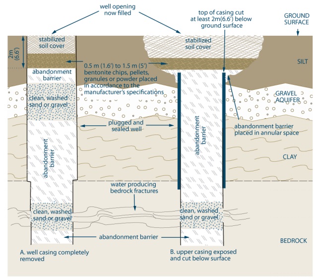
Figure 1 is a cross section diagram of two methods of plugging and sealing abandoned test holes or dewatering wells that are greater than 6.5 cm (2.5 inches) in diameter. Both wells have been originally constructed through the overburden and completed into the bedrock.
The example on the left shows the plugging and sealing of the well with the casing completely removed.
From about 2 metres below the ground surface to the bottom of the well, the example of the left shows clean, washed sand or gravel placed in the well bore adjacent to water producing zones or fractures, to minimize the loss of sealant material and the remainder filled with an abandonment barrier material.
From about 2 metres below the ground surface to the ground surface, the example on the left shows a layer of 50 and 150 centimetres (1.6 to 5 feet) in vertical thickness of bentonite chips, pellets, granules or powder placed in the well opening in accordance with the manufacturer’s specifications, and the remaining well opening to the ground surface filled with soil cover, or other material that is more in keeping with the surface material immediately adjacent to the well opening, to prevent inadvertent or unauthorized access.
The example on the right shows the plugging and sealing of the well with the upper 2 metres (6.6 feet) of casing removed.
From about 2 metres (6.6 feet) below the ground surface to the bottom of the well, the example of the right shows clean, washed sand or gravel placed in the well bore adjacent to water producing zones or fractures, to minimize the loss of sealant material and the remainder filled with an abandonment barrier material.
From about 2 metres (6.6 feet) below the ground surface to the ground surface, the example of the right shows a layer of 50 and 150 centimetres (1.6 to 5 feet) in vertical thickness of bentonite chips, pellets, granules or powder placed in the well opening in accordance with the manufacturer’s specifications, and the remaining well opening to the ground surface filled with soil cover, or other material that is more in keeping with the surface material immediately adjacent to the well opening, to prevent inadvertent or unauthorized access.
- This procedure is typically used for drilled wells and may also be used for direct push, dug and bored wells. It is permitted for any type of well with a diameter greater than 6.5 cm (2.5 inches).
- Abandonment barrier slurries must be placed using a tremie pipe.
- Abandonment barrier must prevent any movement of water, natural gas, contaminants or other materials between subsurface formations (including aquifers) and between a subsurface formation (including an aquifer) and the top of the abandonment barrier.
- Water should be added to the bentonite chips, pellets, granules or powder to start hydration.
- Soil cover can be other material in keeping with existing adjascent surface material. The soil cover must prevent inadvertent and unauthorized access.
- Well opening is typically excavated to remove the top portion of the well casing.
This figure applies to situations where narrow diameter wells (≤ 6.5 cm) are overdrilled to a diameter > 6.5 cm. It also applies to test holes or dewatering wells with a diameter > 6.5 cm that are constructed with flush-mounted well pits (vaults).
The diagram above is not to scale, it is for illustrative purposes for this technical bulletin only and it does not necessarily represent full compliance with other requirements found in the Wells Regulation.
Figure 2: Plugging and Sealing Narrow Diameter Wells ≤ 6.5 cm (2.5 inches)
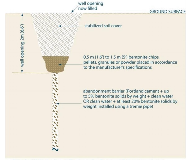
Figure 2 is a cross section diagram of one method of plugging and sealing narrow abandoned test holes or dewatering wells that are less than or equal to 6.5 cm (2.5 inches) in diameter.
The example shows the plugging and sealing of the well with the casing completely removed.
From about 2 metres (6.6 feet) below the ground surface to the bottom of the well, the example shows the well filled with an abandonment barrier material that consists of Portland cement and up to 5 percent solids by weight plus clean water or, as an alternate, clean water plus at least at least twenty percent bentonite solids by weight installed using a tremie pipe.
From about 2 metres (6.6 feet) below the ground surface to the ground surface, the example shows a layer of 50 and 150 centimetres (1.6 to 5 feet) in vertical thickness of bentonite chips, pellets, granules or powder placed in the well opening in accordance with the manufacturer’s specifications, and the remaining well opening to the ground surface filled with soil cover, or other material that is more in keeping with the surface material immediately adjacent to the well opening, to prevent inadvertent or unauthorized access.
- This is for situations where well casing and well screen are being removed or are absent.
- This is typically for narrow diameter drilled, direct push, jetted and driven point wells.
- Abandonment barrier must prevent any movement of water, natural gas, contaminants or other materials between subsurface formations (including aquifers) and between a subsurface formation (including an aquifer) and the top of the abandonment barrier.
- Water should be added to the bentonite chips, pellets, granules or powder to start hydration.
- Well opening is typically excavated to remove the top portion of the well casing.
This figure and associated notes apply to situations where narrow diameter wells (≤6.5 cm) are constructed with flush-mounted well pits (vaults) and the casing and well screen have been removed.
The diagram above is not to scale, it is for illustrative purposes for this technical bulletin only and it does not necessarily represent full compliance with other requirements found in the Wells Regulation.
Figure 3: Plugging and Sealing a Test Hole or Dewatering Well with A Diameter ≤ 6.5 cm & with a Flush-Mounted Well Pit (Vault)
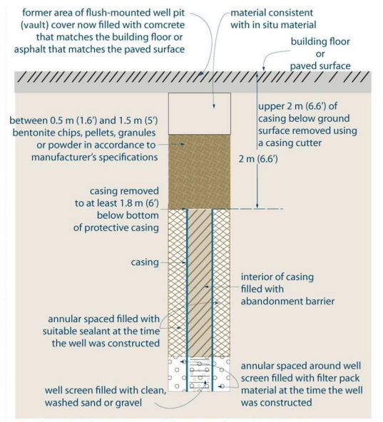
Figure 3 is a cross section diagram of one method of plugging and sealing a test hole or dewatering well that is less than or equal to 6.5 cm (2.5 inches) in diameter and with a flush-mounted well pit (vault).
The example shows the plugging and sealing of the well with the upper 2 metres (6.6 feet) of casing removed. There is a well screen attached to the bottom of the casing. The annular space around the well screen has been filled with filter pack material at the well was constructed. The annular space around the casing has been filled with suitable sealant as the well was constructed.
From about 2 metres (6.6 feet) below the ground surface to the bottom of the casing of the well, the example shows the interior of the well filled with an abandonment barrier material. The interior of the well screen has been filled with clean, washed sand or gravel.
From about 2 metres (6.6 feet) below the ground surface to the ground surface, the example shows a layer of 50 and 150 centimetres (1.6 to 5 feet) in vertical thickness of bentonite chips, pellets, granules or powder placed in the well opening in accordance with the manufacturer’s specifications. The remaining well opening to the ground is filled with material consistent with in-situ material. The top of the ground surface is considered a building floor or a paved surface. The former area of the flush-mounted well pit (vault) cover is now filled with concrete that matches the building floor or asphalt that matches the paved surface.
- If casing and well screen are not being removed, the abandonment barrier must be:
- a slurry of clean water and Portland cement + up to 5% bentonite solids by weight, or
- bentonite chips or pellets that have been screened and placed in accordance with manufacturer’s specifications.
- At least the top 2 m (6.6 ft) of the casing must be removed, if reasonably possible.
- Well opening is typically excavated to remove the top portion of the well casing (not shown).
This figure and associated notes apply to situations where narrow diameter wells (≤6.5 cm) are constructed with flush-mounted well pits (vaults) and the casing and well screen have not been removed.
The diagram above is not to scale, it is for illustrative purposes for this technical bulletin only, and it does not necessarily represent full compliance with other requirements found in the Wells Regulation. It does not include additional considerations such as structural design.
Figure 4: Plugging and Sealing Uncased Narrow Diameter Well < 6.5 cm (2.5 inches)
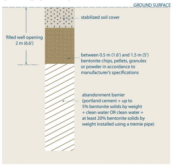
Figure 4 is a cross section diagram of one method of plugging and sealing an uncased narrow abandoned test hole or dewatering well that is less than 6.5 cm (2.5 inches) in diameter.
The example shows the plugging and sealing of the well when the casing and well screen were not installed.
From about 2 metres (6.6 feet) below the ground surface to the bottom of the well, the example shows the well filled with an abandonment barrier material that consists of Portland cement and up to 5 percent solids by weight plus clean water or, as an alternate, clean water plus at least at least twenty percent bentonite solids by weight installed using a tremie pipe.
From about 2 metres (6.6 feet) below the ground surface to the ground surface, the example shows a layer of 50 and 150 centimetres (1.6 to 5 feet) in vertical thickness of bentonite chips, pellets, granules or powder placed in the well opening in accordance with the manufacturer’s specifications, and the remaining well opening to the ground surface filled with stabilized soil cover.
- This is for situations where well casing and well screen were never installed.
- This is typically for narrow diameter drilled, direct push, wells.
- Abandonment barrier must prevent any movement of water, natural gas, contaminants or other materials between subsurface formations (including aquifers) and between a subsurface formation (including an aquifer) and the top of the abandonment barrier.
- Water should be added to the bentonite chips, pellets, granules or powder to start hydration.
The diagram above is not to scale, it is for illustrative purposes for this technical bulletin only and it does not necessarily represent full compliance with other requirements found in the Wells Regulation.
Figure 5: Plugging and Sealing Large Diameter Wells > 65 cm (2.5 ft.) – Alternate Methods
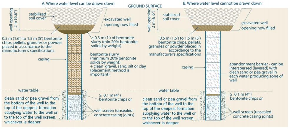
Figure 5 is a cross section diagram of two alternate methods of plugging and sealing abandoned test holes or dewatering wells that are greater than 65 cm (2.5 feet) in diameter. Both wells have been originally constructed into the overburden and below the water table.
The example on the left is numbered “A” and is for scenarios where the water level can be drawn down in the well. The example on the right is numbered “B” and is for scenarios where the water level cannot be drawn down in the well.
The examples on the left (“A”) and right (“B”) show the plugging and sealing of the well with the upper 2 metres (6.6 feet) of casing removed. The casing is made up of concrete tiles. The bottom concrete tiles below the water table are considered well screen as the concrete casing joints are unsealed.
From about 2 metres below the ground surface to the bottom of the well, the examples of the left and right show clean, sand or pea gravel placed from the bottom of the well to the top of the deepest formation supplying water to the well or to the top of the well screen, whichever is deeper. A greater than or equal to 0.1 metre (0.4 inches) of bentonite chips is placed on top of the clean sand or pea gravel.
The example on the left (“A”) shows a layer of bentonite slurry (minimum 20 percent bentonite solids by weight) mixed with clean gravel, sand, silt or clay (placement is important) is placed in the well on top of the bentonite chips. A layer that is greater than or equal to 0.3 metres (1 foot) of bentonite slurry (minimum 20 percent bentonite solids by weight) is placed on top of the bentonite mixed with gravel, sand, silt or clay. The top of the bentonite slurry shall be about 2 metres (6.6 feet) below the ground surface.
From about 2 metres below the ground surface to the ground surface, the example on the left shows a layer of 50 and 150 centimetres (1.6 to 5 feet) in vertical thickness of bentonite chips, pellets, granules or powder placed in the well opening in accordance with the manufacturer’s specifications, and the remaining well opening to the ground surface filled with soil cover, or other material that is more in keeping with the surface material immediately adjacent to the well opening, to prevent inadvertent or unauthorized access.
From about 2 metres below the ground surface to the bottom of the well, the example on the right (“B”) shows clean, washed sand or gravel placed in the well bore adjacent to water producing zones or fractures, to minimize the loss of sealant material and the remainder filled with an abandonment barrier material.
The example on the right (“B”) shows a layer of abandonment barrier placed on top of the bentonite chips. The abandonment barrier can be interspersed (layered) with clean sand or pea gravel in each water producing zone. The top of the abandonment barrier shall be about 2 metres (6.6 feet) below the ground surface.
From about 2 metres below the ground surface to the ground surface, the example of the right shows a layer of 50 and 150 centimetres (1.6 to 5 feet) in vertical thickness of bentonite chips, pellets, granules or powder placed in the well opening in accordance with the manufacturer’s specifications, and the remaining well opening to the ground surface filled with soil cover, or other material that is more in keeping with the surface material immediately adjacent to the well opening, to prevent inadvertent or unauthorized access.
- This alternate method is typically for large diameter dug, bored or augered wells.
- Abandonment barrier slurries must be placed using a tremie pipe.
- Soil cover can be other material in keeping with existing adjascent surface material. The soil cover must prevent inadvertent and unauthorized access.
- Abandonment barrier must prevent any movement of water, natural gas, contaminants or other materials between subsurface formations (including aquifers) and between a subsurface formation (including an aquifer) and the top of the abandonment barrier.
- Water should be added to the bentonite chips, pellets, granules or powder to start hydration.
- Well opening is typically excavated to remove the top portion of the well casing.
The well in Diagram ‘A’ of Figure 5, above, is filled with a bentonite slurry (minimum 20% bentonite solids by weight) + clean gravel, sand, silt or clay. In this case, the placement method is important. See the placement method in step 3 of the How to Abandon a Test Hole or Dewatering Well – Nine (9) Steps in this technical bulletin.
The diagram above is not to scale, it is for illustrative purposes for this technical bulletin only, and it does not necessarily represent full compliance with other requirements found in the Wells Regulation.
Figure 6: Plugging and Sealing a Drilled Well Through a Large Diameter Dug Well or Well Pit
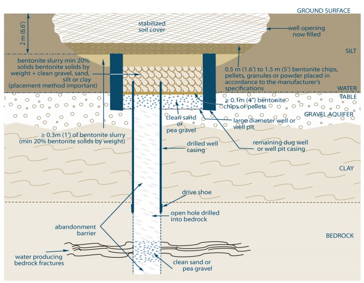
Figure 6 is a cross section diagram of plugging and sealing an abandoned drilled well test hole or dewatering well through a large diameter dug well or well pit. The drilled well has been originally constructed through the overburden and completed into the bedrock. The drilled portion of the well is obtaining groundwater from water producing bedrock fractures. The drilled portion of the well has a casing that extends from within the dug well into the upper portion of the bedrock. The bottom of the casing has a drive shoe. The top of the casing is located 2 metres below the ground surface. The remainder of the drilled well in the bedrock is an open hole.
A clay overburden deposit overlies the bedrock. A gravel overburden deposit overlies the clay and contains an aquifer. A silt deposit overlies the gravel to the ground surface. The water table is located at the silt – gravel interface. The dug portion of the well is obtaining groundwater from the gravel aquifer. The remaining dug well or well pit casing extends from 2 metres below the ground surface to within the gravel deposit.
From about the bottom of the dug well to the bottom of the well, the drilled portion of the well has been filled with clean sand or pea gravel placed in the well bore adjacent to water producing fractures, to minimize the loss of sealant material and the remainder filled with an abandonment barrier material.
From about 2 metres below the ground surface to the bottom of the dug well or well pit, clean sand or pea gravel has been placed from the bottom of the dug well (or well pit) to the top of the gravel aquifer (which is also the water table). A greater than or equal to 0.1 metre (0.4 inches) of bentonite chips is placed on top of the clean sand or pea gravel. A layer of bentonite slurry (minimum 20 percent bentonite solids by weight) mixed with clean gravel, sand, silt or clay (placement method is important) is placed in the well on top of the bentonite chips. A layer that is greater than or equal to 0.3 metres (1 foot) of bentonite slurry (minimum 20 percent bentonite solids by weight) is placed on top of the bentonite mixed with gravel, sand, silt or clay. The top of the bentonite slurry shall be about 2 metres (6.6 feet) below the ground surface.
From about 2 metres below the ground surface to the ground surface, a layer of 50 and 150 centimetres (1.6 to 5 feet) in vertical thickness of bentonite chips, pellets, granules or powder has been placed in the well opening in accordance with the manufacturer’s specifications, and the remaining well opening to the ground surface is filled with stabilized soil cover.
- Requirements for wells > 6.5 cm (2.5 inches) apply to the drilled portion of the well, and alternate method for wells > 65 cm (2.5 ft) could be used from the bottom of the dug well or well pit up to the ground surface.
- Abandonment barrier slurries must be placed using a tremie pipe.
- Soil cover can be other material in keeping with existing adjascent surface material. The soil cover must prevent inadvertent and unauthorized access.
- Abandonment barrier must prevent any movement of water, natural gas, contaminants or other materials between subsurface formations (including aquifers) and between a subsurface formation (including an aquifer) and the top of the abandonment barrier.
- Water should be added to the bentonite chips, pellets, granules or powder to start hydration.
- Well opening is typically excavated to remove the top portion of the well casing.
If water cannot be pumped down to the top of the 0.1 m (4 inches) of bentonite chips or pellets see Figure 5 (B) for material placement method. If present, a well pit floor made of suitable sealant must be removed in this case to allow for the placement of clean sand or pea gravel.
The diagram above is not to scale, it is for illustrative purposes for this technical bulletin only, and it does not necessarily represent full compliance with other requirements found in the Wells Regulation.
Figure 7: Removal of Well Screen, Point and Riser(s) Commonly Part of a Construction Dewatering System Using a Jetting Method
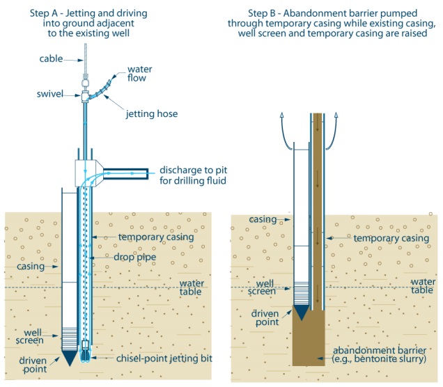
Figure 7 is a cross section diagram of removing a well screen, point and riser(s) that are commonly part of a construction dewatering system using a jetted method.
The diagram shows two steps, Step A (Jetting and driving into ground adjacent to the existing well) and Step B (Abandonment barrier pumped through temporary casing while existing casing, well screen and temporary casing are raised).
On the left side of the diagram, Step A shows the jetting and driving equipment being placed into the ground adjacent to the existing well. The existing well consists of a casing that extends from above the ground surface into the subsurface below the water table. The bottom of the casing is attached to a well screen. A driven point is attached to the bottom of the well screen.
The jetting and driving equipment is located immediately to the right of the well. The jetting and driving equipment consists of a temporary casing that extends from above the ground surface into the subsurface. The bottom of the casing is located beside the well screen of the well. A connection has been made at the top of the temporary casing that allows for the connection of a horizontal waterline the top of the casing. A drop pipe extends from above the top of the temporary casing through the interior of the casing to the bottom of the temporary casing. The drop pipe is attached to a chisel-point jetting bit that is located below the temporary casing. A swivel attaches the top of the drop pipe to a jetting hose. A cable has been attached to the top of the swivel and drop pipe. A blue line with arrows shows water flowing through the jetting house into the drop pipe and out of the chisel-point jetting bit. The water and cuttings circulate up around the drop pipe and within the temporary casing to the horizontal water line at the top of the temporary casing. The water and cuttings move through the horizontal water line and discharge to a pit for drilling fluid.
On the right side of the diagram, Step B shows the casing, well screen and driven-point of the well and temporary casing immediately beside the well being pulled out of the ground. The drop pipe and chisel-point jetting bit have already been removed from the temporary casing. At this stage of removal, the well screen is located at the water table. During the removal of the well and temporary casing, abandonment barrier (e.g., bentonite slurry) is being pumped through the temporary casing and filling the void space created by the removal of the well and temporary casing.
This figure is not to scale, it is for illustrative purposes for this technical bulletin only and it does not necessarily represent full compliance with other requirements found in the Wells Regulation.
Figure 8: Removal of Well Screen, Point and Riser(s) Commonly Part of a Construction Dewatering System Using a Driven Method
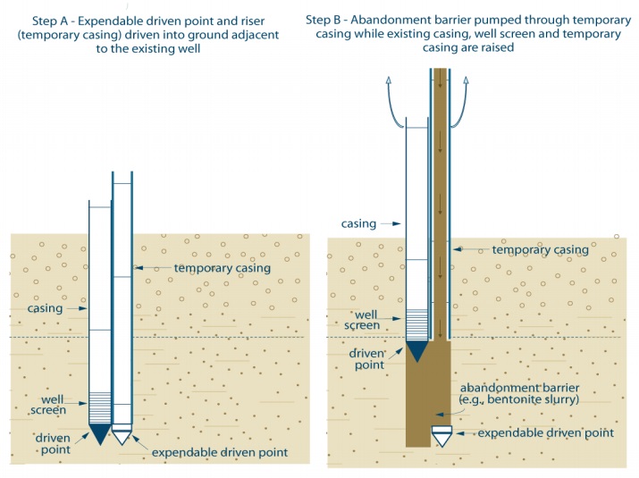
Figure 8 is a cross section diagram of removing a well screen, point and riser(s) that are commonly part of a construction dewatering system using a driven method.
The diagram shows two steps, Step A [Expendable driven point and riser (temporary casing) driven into ground adjacent to the existing well] and Step B (Abandonment barrier pumped through temporary casing while existing casing, well screen and temporary casing are raised).
On the left side of the diagram, Step A shows the driving equipment being placed into the ground adjacent to the existing well. The existing well consists of a casing that extends from above the ground surface into the subsurface below the water table. The bottom of the casing is attached to a well screen. A driven point is attached to the bottom of the well screen.
The driving equipment is located immediately to the right of the well. The driving equipment consists of a temporary casing that extends from above the ground surface into the subsurface. An expendable driven point is located at the bottom of the casing. The expendable driven point is located beside the well’s driven-point.
On the right side of the diagram, Step B shows the casing, well screen and driven-point of the well and temporary casing immediately beside the well being pulled out of the ground. The expendable driven point remains in the ground at the same location as in Step A. During the removal of the well and temporary casing, abandonment barrier (e.g., bentonite slurry) is being pumped through the temporary casing and filling the void space created by the removal of the well and temporary casing.
This figure is not to scale, it is for illustrative purposes for this technical bulletin only and it does not necessarily represent full compliance with other requirements found in the Wells Regulation.
Footnotes
- footnote[1] Back to paragraph A list of the seventeen technical bulletins is shown in the Additional Information Sources section near the end of this technical bulletin.
- footnote[2] Back to paragraph A “test hole” means a well that, (a) is made to test or to obtain information in respect of ground water or an aquifer, and (b) is not used or intended for use as a source of water for agriculture or human consumption, subsection 1(1) of the Wells Regulation, e-laws.
- footnote[3] Back to paragraph A “dewatering well” means a well that is not used or intended for use as a source of water for agriculture or human consumption and that is made, (a) to lower or control the level of ground water in the area of the well, or (b) to remove materials that may be in the ground water, subsection 1(1) of the Wells Regulation, e-laws.
- footnote[4] Back to paragraph Sections 36 to 50 of the Ontario Water Resources Act, R.S.O. 1990, c. O. 40, e-laws.
- footnote[5] Back to paragraph Sections 36 to 50 of the Ontario Water Resources Act, R.S.O. 1990, c. O. 40, e-laws.