Technical Bulletin - Wells Regulation - Constructing New Multi-Level Monitoring Test Holes
The purpose of this technical bulletin is to summarize the information on the initial construction of new multi-level monitoring test holes found in the Test Holes and Dewatering Wells – Requirements and Best Management Practices manual published by the Ministry of the Environment, April 2014.
This technical bulletin is one in a series of seventeen
- may have a new multi-level monitoring test hole
footnote 2 or constructed in the future, or - currently owns a multi-level monitoring test hole.
The purpose of this technical bulletin is to:
- summarize the information found in the Test Holes and Dewatering Wells – Requirements and Best Management Practices manual published by the Ministry of the Environment, April 2014 (hereon in referred to as the “Manual”) regarding the initial construction of new multi-level monitoring test holes, and
- present some construction steps that must be undertaken and materials that must be used to meet the requirements of Regulation 903 (Wells Regulation), as amended, made under the Ontario Water Resources Act.
Additional information on new well construction is provided in the Wells Regulation – Completing the Structure of the New Test Hole or Dewatering Well technical bulletin.
Exemption - Depth of Well
The minimum well depth requirements found in the Wells Regulation do not apply to a new multi-level monitoring test hole.
The regulatory exemption regarding the depth of a test hole allows for well technicians, engineers and geoscientists to use their professional expertise to design and install test holes and dewatering wells on a case by case basis, according to the conditions at a particular site.
Casing and Well Screen in a New Multi-Level Monitoring Test Hole
A test hole commonly has a casing and may also have a well screen.
- Casing
- A “casing” means pipe, tubing or other material installed in a well to support its sides, but does not include a well screen. Casing keeps the hole open, prevents overburden materials from entering the well and accommodates pumping equipment. Casing may also be used to seal off unwanted formations.
Casing requirements and exemptions in the Wells Regulation apply:
- to the flexible or rigid plastic tubing (casing) and a permanent steel or plastic outer casing that is placed around the bundle of tubes in a new bundled multi-level monitoring test hole,
- plastic, stainless steel, polytetrafluoroethylene or fiberglass in new nested multi-level monitoring test hole, and
- plastic, stainless steel, multi-channel medium density polyethylene (MDPE) or polyurethane-coated nylon fabric in a new dedicated multi-level monitoring test hole.
- Well screen
- “Well screen” means a perforated pipe or tubing, unsealed concrete tiles or other material installed in a well to filter out particulate matter and forms the water intake zone.
Well Screen requirements and exemptions in the Wells Regulation apply to:
- perforations or slots in the flexible or rigid plastic tubing for a new bundled multi-level monitoring test hole,
- perforations or slots in plastic, stainless steel, polytetrafluoroethylene or fiberglass manufactured well screens attached to the bottom of the casings in a new nested multi-level monitoring test hole,
- perforations or slots in a plastic, stainless steel, polytetrafluoroethylene or fiberglass risers for new nested multi-level monitoring test hole, and
- Screened, or unscreened, ports in a new dedicated multi-level monitoring test hole.
New Test Hole Operating More than 180 days After the Completion of the Well’s Structural Stagefootnote 3
For information on casing and well screen requirements and exemptions for multi-level monitoring test holes operating more than 180 days, see the Wells Regulation and the Wells Regulation – Constructing New Test Holes & Dewatering Wells technical bulletin.
New Test Hole Operating no Longer than 180 Days after the Completion of the Well’s Structural Stage
For information on casing and well screen requirements and exemptions for multi-level monitoring test holes operating not later than 180 days after the completion of the well’s structural stage, see the Wells Regulation and the Wells Regulation – Constructing New Test Holes & Dewatering Wells in Operation for Not Longer Than 180 Days technical bulletin.
All New Multi-level monitoring Test Holes
Unlike water supply wells, it is not necessary for the person constructing a new multi-level monitoring test hole to follow:
- the casing standards for material type and wall thickness established in the Wells Regulation,
- the casing length requirements, and
- the requirements to seal the bottom of the casing into bedrock.
In the case of a new nested or bundled multi-level monitoring test hole, the person constructing the well must comply with the following requirements:
- all casings attached to well screens must extend to at least 40 cm (16 inches) above the highest point on the ground surface within a 3m (10') radius from the outside of the casing after the ground surface is properly mounded and meets the surface drainage requirements; or
- any permanent outer casing must extend to at least 40 cm (16 inches) above the highest point on the ground surface within a 3m (10') radius from the outside of the casing after the ground surface is properly mounded and meets the surface drainage requirements.
All casing height measurements must be taken upon completion of the well’s structural stage.
In the case of a new dedicated multi-level monitoring test hole, the person constructing the well must comply with the following requirements:
- the casing of the dedicated system must extend to at least 40 cm (16 inches) above the highest point on the ground surface within a 3 m (10') radius from the outside of the casing after the ground surface is properly mounded and meets the surface drainage requirements, or
- any permanent outer casing must extend to at least 40 cm (16 inches) above the highest point on the ground surface within a 3m (10') radius from the outside of the casing after the ground surface is properly mounded and meets the surface drainage requirements.
All casing height measurements must be taken upon completion of the well’s structural stage.
Under certain circumstances, an exemption to the height of casing exists for:
- certain driven and jetted point multi-level monitoring test holes, and
- all test holes using a flush-mounted watertight commercially manufactured well cover.
For further information on the casing height exemptions see the Wells Regulation and the Wells Regulation – Completing the Structure of the New Test Hole or Dewatering Well technical bulletin.
For further information on casing and well screen, see Chapter 6 of the Manual: Constructing the Hole, Casing & Covering the Test Hole or Dewatering Well.
Annular Space in a New Multi-Level Monitoring Test Hole
“Annular space” means an open space between a casing or well screen and the side of a well, and includes space between overlapping casings within the well.
A properly sealed annular space will reduce the risk of water supply contamination from a number of contaminants such as bacteria, salt, pesticides, fertilizers and gasoline.
Properly sealing the annular space includes the use of a suitable sealant. Suitable sealant is a slurry of clean water and at least 20% bentonite (manufactured clay product) solids by weight or other equivalent material.
New Test Hole Operating not Later than 180 Days after the Completion of the Well’s Structural Stage
Instead of following the annular space requirements in the Wells Regulation and outlined in Chapter 7 of the Manual: Annular Space and Sealing, the person constructing a new multi-level monitoring test hole without a permanent outer casing must ensure that:
- there is no movement of water, natural gas, contaminants or other material between subsurface formations or between a subsurface formation and the ground surface in any annular space along a well casing or between overlapping casings, and
- the test hole is scheduled to be abandoned within 180 days of the completion of its structural stage.
New Test Hole Operating Later than 180 days After the Completion of the Well’s Structural Stage
The person constructing the new test hole must install a permanent outer casing for any new multi-level monitoring test hole that will be in operation for more than 180 days after the completion of the well’s structural stage.
Depending on the type of well construction method used, the person constructing the new test hole must follow the requirements in the Wells Regulation that are listed in Chapter 7 of the Manual: Annular Space & Sealing, Table 7-1A and Table 7-1B, with necessary modifications, to create and seal any annular space beside the permanent outer casing.
As a necessary modification for a multi-level monitoring system installed using drilling, augering or sonic equipment, the depth of the annular space must extend from the ground surface to at least the bottom of the permanent outer casing or 6 m (19.7'), whichever is less.
When a smaller diameter casing, or casings, is (are) installed within the permanent outer casing, the annular space between the casings of different diameters must be sealed with a suitable sealant to prevent the entry of surface water and other foreign materials.
If any groundwater is leaking into the annular space between the casings of different diameters, the annular space between the casings must be sealed, with necessary modifications, in accordance with Wells Regulation requirements that are outlined in Chapter 7 of the Manual: Annular Space & Sealing, Table 7-1 A and Table 7-1B. The annular space between casings of a well constructed by the use of a driven point is not required to be sealed in accordance with the Wells Regulation but is required to be sealed with a suitable sealant. See Chapter 7 of the Manual: Annular Space & Sealing for further information.
Necessary modifications can include creating a properly sized hole that allows for the installation of centralizers to centre and separate all casings.
Annular Space below the Permanent Outer Casing
Person Constructing a Well
Although a person constructing a well is not specifically required to seal the casings between well screens or ports in a multi-level monitoring test hole below the permanent outer casing; the person must do what is necessary as the Ontario Water Resources Act prohibits any person from discharging or causing or permitting the discharge of any material of any kind into any waters that may impair the quality of any waters. This includes preventing contaminated groundwater from impairing the quality of other groundwater zones when constructing a well.
The regulatory exemptions regarding sealing the annular space below the permanent outer casing allow for well technicians, engineers and geoscientists to use their professional expertise to design and install multi-level test holes on a case by case basis, thereby enabling the testing and sampling of various groundwater intervals while preventing contamination.
Well Owner
Persons using the above professional expertise and the well owner should be aware of the following requirement.
If the test hole or dewatering well acts as a pathway for the movement of:
- natural gas,
- contaminants, or
- other materials
between subsurface formations (including aquifers) or between the ground surface and a subsurface formation and where the movement may impair the quality of any waters, the well owner, must do one of the following:
- take measures to prevent the movement of the above materials and ensure the measures are functional at all times, or
- immediately abandon the well.
For further information, see Chapter 8 of the Manual: Multi-Level Monitoring Test Holes.
Best Management Practices
Best management practices are recommended actions or steps that exceed the minimum regulatory requirements to better protect the groundwater and the natural environment.
The Ministry of the Environment has developed and presented a number of best management practices in Chapter 8 of the Manual: Multi-Level Monitoring Test Holes for persons who construct wells, professional engineers, professional geoscientists and well owners.
The best management practices are intended to provide a practice or combination of practices based on research, field-experience, and expert review, which are both effective and practical for multi-level monitoring test holes.
Persons who are designing and constructing a multi-level test hole should review and apply the relevant best management practices found in Chapter 8 of the Manual: Multi-Level Monitoring Test Holes.
Monitoring Wells Under Records of Site Condition Regulation
There are additional well construction requirements for monitoring wells that are used in an assessment in support of a record of site condition for a property.
O. Reg. 153/04
- a phase one environmental site assessment; and
- a phase two environmental site assessment.
A monitoring well is considered a test hole. For clarification on the term “monitoring well”
Implications for the Qualified Person
The qualified person
See the Wells Regulation – Constructing New Test Holes & Dewatering Wells or Wells Regulation – Constructing New Test Holes & Dewatering Wells in Operation for No Longer Than 180 Days technical bulletins for information on the requirements that apply to a multi-level monitoring test hole that is required as part on an environmental site assessment.
Covering Well During Construction
The Wells Regulation requires that whenever a test hole or dewatering well, under construction is left unattended, including during a minor alteration or the installation of a pump, the person constructing the well must cover the upper open end of the test hole or dewatering well securely in a manner sufficient to prevent the entry of surface water and other foreign materials into the well.
Surface Drainage
The person constructing the well must ensure that the surface drainage is such that water will not collect or pond in the vicinity of the test hole or dewatering well.
Completing the Well, Well Record and Tagging
Information on well caps, well covers and mounding is provided in the Wells Regulation – Completing the Structure of the Test Hole or Dewatering Well technical bulletin.
Information on venting and pump installation is provided in the Wells Regulation – Installing Equipment in a Test Hole or Dewatering Well technical bulletin.
Information on completing and submitting a well record and tagging a test hole or dewatering well is provided in the Wells Regulation – Well Record, Reporting & Tagging for a Test Hole & Dewatering Well technical bulletin.
Notifications (Natural Gas)
Where a test hole or dewatering well is constructed and natural gas is encountered, the person constructing the well must immediately notify the well purchaser, the owner of the land on which the well is located and the Director under the Act of the condition.
To prepare for on-site specific conditions such as hazardous gas or contamination, see the best management practices and information found in the Encountering Contamination and Water Quality Problems section in Chapter 6 of the Manual: Constructing the Hole, Casing & Covering the Test Hole or Dewatering Well.
If a test hole or dewatering well produces natural gas, the well owner must immediately take action to ensure that the gas will not present a hazard. For further information on the appropriate action a well owner must take, see the Wells Regulation, the Wells Regulation – Well Abandonment: When to Plug and Seal a Test Hole or Dewatering Well technical bulletin and Chapter 16 of the Manual: Well Abandonment: When to Plug and Seal a Test Hole or Dewatering Well.
Figures at End of this Technical Bulletin
Figures 1 to 2 show cross-sectional illustrations and relevant graphics for various types of new multi-level monitoring test holes including the length of casing, types of well screen, minimum hole size, filter pack and suitable sealant in the annular space around the casing.
Exempted Wells & Shallow Works
The Wells Regulation exempts certain types of wells, such as a pond or trench, from the Wells Regulation and from the sections on licensing of the Ontario Water Resources Act that pertain to wells
A person who constructs, maintains or abandons a shallow works that meets the conditions set out in section 1.1 of the Wells Regulation:
- is exempt from the sections on licencing of the Ontario Water Resources Act that pertain to wells,
footnote 8 and - need only meet the requirements found in section 1.1 of the Wells Regulation.
The shallow works exemption contained in section 1.1 of the Wells Regulation does not apply to a monitoring well that is constructed as part of a phase one or two environmental site assessment for a record of site condition
See the Wells Regulation – Understanding a Well, Test Hole and Dewatering Well and Wells Regulation – Shallows Works technical bulletins for further information.
Water Supply Wells
Certain licensing and construction requirements for water supply wells are different from the requirements for test holes and dewatering wells as defined by the Wells Regulation. For further information on the requirements for water supply wells see the Water Supply Wells – Requirements and Best Management Practices manual, published by the Ministry of the Environment, December 2009 and the Wells Regulation.
Additional Information Sources
The seventeen technical bulletins on test holes and dewatering wells are:
- Wells Regulation – Understanding the Meaning of Well, Test Hole and Dewatering Well
- Wells Regulation – Shallow Works Test Holes & Dewatering Wells
- Wells Regulation – Exempted Activities Performed on Wells, Including Test Holes & Dewatering Wells
- Wells Regulation – Test Hole and Dewatering Well Licensing
- Wells Regulation – Licensing (Class 5) for Individuals who Perform Tests on Wells
- Wells Regulation – Site Considerations & Initial Planning for Test Holes & Dewatering Wells
- Wells Regulation – Constructing New Uncased Test Holes & Dewatering Wells in Operation for No Longer than 30 Days
- Wells Regulation – Constructing New Test Holes & Dewatering Wells in Operation for No Longer than 180 Days
- Wells Regulation – Constructing New Test Holes & Dewatering Wells
- Wells Regulation – Constructing New Multi-level Monitoring Test Holes
- Wells Regulation – Completing the Structure of the New Test Hole or Dewatering Well
- Wells Regulation – Flowing Test Holes & Dewatering Wells
- Wells Regulation – Test Hole & Dewatering Well Maintenance
- Wells Regulation – Well Record, Reporting & Tagging for a Test Hole & Dewatering Well
- Wells Regulation – Test Hole & Dewatering Well Repairs & Alterations
- Wells Regulation – Well Abandonment - When to Plug & Seal a Test Hole or Dewatering Well
- Wells Regulation – Well Abandonment - How to Plug & Seal a Test Hole or Dewatering Well
These technical bulletins are available on the Ontario website.
Further information on constructing a multi-level monitoring test hole can be found in Chapter 8 of the Manual: Multi-Level Monitoring Test Holes.
A copy of the Test Holes and Dewatering Wells – Requirements and Best Management Practices manual can be obtained on the Ontario website.
A copy of the Ontario Water Resources Act, Wells Regulation and other regulations can be obtained from the e-Laws website.
The publications are also available by calling the Publications Information Centre at 1-800-565-4923 or (416) 325-4000.
For further information about wells, contact the Wells Help Desk at 1-888-396-9355 (Well) or the nearest Ministry of the Environment office listed in the blue pages of the telephone directory.
For further information about wells, contact the Wells Help Desk at 1-888-396-9355 (Well) or the nearest Ministry of the Environment office listed in the blue pages of the telephone directory.
Notice: This bulletin is being provided for information purposes only and is not intended, nor should it be construed as providing legal advice in any circumstances. The applicable environmental legislation, including the following, should be consulted.
- Ontario Water Resources Act, R.S.O. 1990, c. O. 40
- R.R.O. 1990, Regulation 903 (Wells) as amended made under the Ontario Water Resources Act, R.S.O. 1990, c. O. 40
- Ontario Regulation 153/04 as amended made under the Environmental Protection Act, R.S.O. 1990, c. E. 19
Legislation and regulations change from time to time so it is essential that the most current versions be used.
PIBS 9621e
Disponble en Français
Figure 1: Examples of Multi-Level Monitoring Systems (Must be Scheduled to be Abandoned Not Later Than 180 Days After Completing Structural Stage)
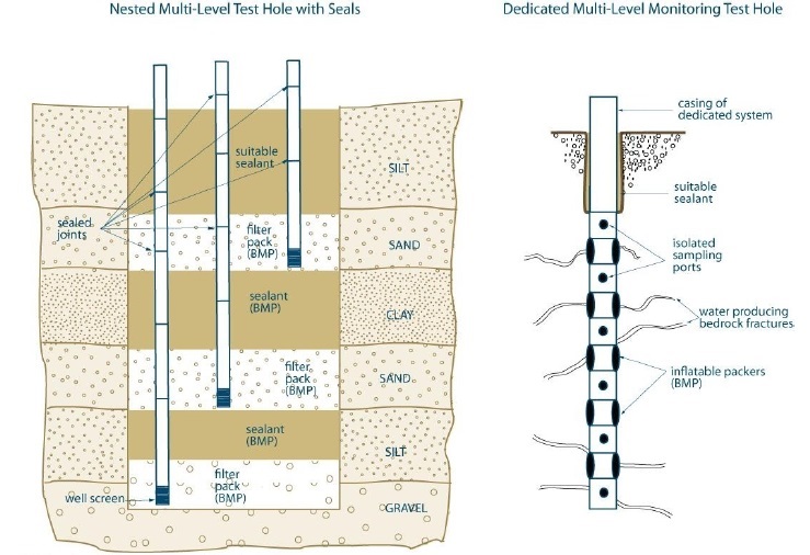
BMP = Best Management Practices
This diagram shows two examples of the many types of multi-level monitoring systems. For test holes and dewatering wells that are not scheduled to be abandoned within 180 days, the Wells Regulation requires that a continuous column of suitable sealant be placed above the filter pack material (see subparagraph ii, paragraph 1 of subsection 14.4(2) of the Wells Regulation). The two systems depicted above require separate zones of sealant material to separate the different well screens and filter packs or ports. As such, these systems cannot meet the regulatory requirements for a test hole that will be in operation for more than 180 days and must be scheduled to be abandoned within that time. See Figure 2 in this technical bulletin for a multi-level monitoring system installed with a permanent outer casing.
This figure is not to scale, it is for illustrative purposes for this technical bulletin only and does not necessarily represent full compliance with the requirements found in the Wells Regulation.
Figure 2: Examples of Multi-Level Monitoring Systems (Not Scheduled to be Abandoned Within 180 Days After Completing Structural Stage)
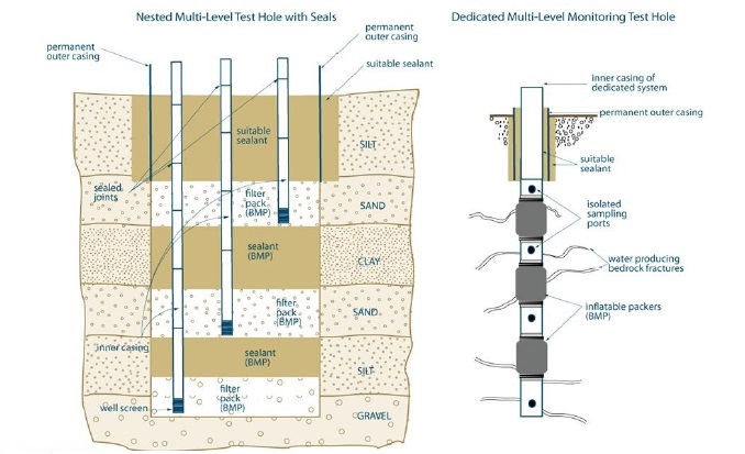
BMP = Best Management Practices
- This diagram shows two examples of the many types of multi-level systems. To operate a new multi-level monitoring test hole longer than 180 days, a person must install a permanent outer casing around the dedicated system or inner casings.
- As a best management practice, the permanent outer casing should extend to at least 6 metres (19.7 feet) from the ground surface or as close to the top of the upper screen or port interval as possible.
- An annular space must be created around the permanent outer and then filled with a suitable sealant as described in Chapter 8: Multi-Level Monitoring Test Holes and Chapter 7: Annular Space & Sealing in the manual.
- A suitable sealant, such as a bentonit product, cement product or an inflatable packer should be properly placed between ports or well screens, except in the case of a dedicated system that employs a liner.
- If groundwater is entering between the inner casing(s) and the permanent outer casing, the enture annular space from the inner casing(s) to the permanent outer casing must be sealed (with necessary modifications). The proper sealing process is described in Chapter 7 of the Manual: Annular Space & Sealing and must be followed unless the new test hole was constructed by the use of a driven points. In all cases, the annular space between the inner casing(s) and permanent outer casing must be sealed with suitable sealant to prevent the entry of surface water and other foreign materials.
This figure is not to scale, it is for illustrative purposes for this technical bulletin only and does not necessarily represent full compliance with the requirements found in the Wells Regulation.
Footnotes
- footnote[1] Back to paragraph A list of the seventeen technical bulletins is shown in the Additional Information Sources section near the end of this technical bulletin.
- footnote[2] Back to paragraph A “test hole” means a well that, (a) is made to test or to obtain information in respect of ground water or an aquifer, and (b) is not used or intended for use as a source of water for agriculture or human consumption, subsection 1(1) of the Wells Regulation, Ontario Water Resources Act.
- footnote[3] Back to paragraph A well’s structural stage is complete on the day on which the well is capable of being used for the purpose for which it was constructed but for, (a) compliance with section 15; (b) the installation of a pump; or (c) any alterations necessary to accommodate pumping, monitoring, sampling, testing or water treatment equipment.
- footnote[4] Back to paragraph Ontario Regulation 153/04 as amended made under the Environmental Protection Act, R.S.O. 1990, c. E. 19, Environmental Protection Act.
- footnote[5] Back to paragraph A “monitoring well” means a well that is a test hole as defined in Regulation 903 of the Revised Regulations of Ontario 1990 (Wells) made under the Ontario Water Resources Act, subsection 22(1) of Ontario Regulation 153/04 as amended made under the Environmental Protection Act, R.S.O. 1990, c. E. 19, Environmental Protection Act.
- footnote[6] Back to paragraph See the definition of Qualified Person in Chapter 2 Definitions and Clarifications of the Test Holes and Dewatering Wells – Requirements and Best Management Practices Manual and section 5 of Ontario Regulation 153/04 as amended made under the Environmental Protection Act, R.S.O. 1990, c. E. 19, Environmental Protection Act.
- footnote[7] Back to paragraph Sections 36 to 50 of the Ontario Water Resources Act, R.S.O. 1990, c. O. 40, Ontario Water Resources Act.
- footnote[8] Back to paragraph Sections 36 to 50 of the Ontario Water Resources Act, R.S.O. 1990, c. O. 40, Ontario Water Resources Act.
- footnote[9] Back to paragraph Ontario Regulation 153/04 as amended made under the Environmental Protection Act, R.S.O. 1990, c. E. 19, Environmental Protection Act.