Technical Bulletin - Wells Regulation - Construction New Test Holes and Dewatering Wells
The purpose of this technical bulletin is to summarize the information on the initial construction of new test holes and dewatering wells found in the Test Holes and Dewatering Wells – Requirements and Best Management Practices manual published by the Ministry of the Environment, April 2014.
This technical bulletin is one in a series of seventeen
may have a new test hole
footnote 2 or dewatering wellfootnote 3 - currently owns a test hole or dewatering well.
The purpose of this technical bulletin is to:
- summarize the information found in the Test Holes and Dewatering Wells – Requirements and Best Management Practices manual published by the Ministry of the Environment, April 2014 (hereon in referred to as the “Manual”) regarding the initial construction of new test holes and dewatering wells, and
- present some construction steps that must be undertaken and materials that must be used to meet the requirements of Regulation 903 (Wells Regulation), as amended, made under the Ontario Water Resources Act.
Additional information on new well construction is provided in the Wells Regulation – Completing the Structure of the New Test Hole or Dewatering Well technical bulletin.
If the test hole or dewatering well is scheduled to be abandoned not later than 180 days after completion of the well’s structural stage
footnote 4 If the test hole or dewatering well is scheduled to be abandoned not later than 30 days after completion of the well’s structural stage, the person constructing the well can, as an alternative follow the requirements described in the Wells Regulation – Constructing New Test Holes & Dewatering Wells in Operation for No Longer Than 30 Days technical bulletin.
Choosing a Construction Method
Successful completion of a test hole or dewatering well depends on the use of equipment and materials that are appropriate for the environmental conditions and geological formations encountered at a site. It is important to consider the characteristics of the drill rig or other well construction equipment including the cutting action and any flushing medium (i.e., type of drilling fluid and its circulation path)
The construction method:
- should be able to penetrate the geological formation,
- should allow the person constructing the test hole or dewatering well to get representative samples of geological formation material, to identify the boundaries of permeable zones and contaminated zones,
- must allow for the proper recording of formations, including aquifers, encountered during construction,
- must not contaminate the groundwater or the environment, and
- unless otherwise exempt, must meet the requirements of the Wells Regulation.
In many cases, the same equipment is used to construct more than one test hole or dewatering well for a project. Where there is no risk of contamination, the equipment does not have to be cleaned after each test hole or dewatering well is constructed before it can be re-used. To reduce the risk of contamination, however, an effective plan for decontamination of the equipment will help prevent the following:
- introduction of contaminants from one site to another site,
- contamination of clean areas,
- cross-contamination between formations, including aquifers,
- cross-contamination of individual samples,
- equipment breakdown,
- accidental exposure of personnel to contaminants, and
- non-compliance with regulatory cleanup standards.
The following standards contain procedures for equipment decontamination:
- ASTM D5088 – 02(2008) – “Standard Guide for Decontamination of Field Equipment Used at Nonradioactive Waste Sites,” (DOI:10.1520/D5088-02R08)
footnote 5 - ASTM D5608 – 01(2006) – “Standard Guide for Decontamination of Field Equipment Used at Low Level Radioactive Waste Sites,” (DOI:10.1520/D5608-01R06)
footnote 6
Table 6-1 in Chapter 6 of the Manual: Constructing the Hole, Casing & Covering the Test Hole or Dewatering Well provides methods, characteristics, advantages and disadvantages of various well construction systems in particular formations.
Table 6-2 in Chapter 6 of the Manual: Constructing the Hole, Casing & Covering the Test Hole or Dewatering Well provides some appropriate types of construction equipment systems, which can be used to construct wells in particular environments and formations.
Exemption – Depth of Well
The minimum well depth requirements found in the Wells Regulation do not apply to a new test hole or dewatering well.
The regulatory exemption regarding the depth of a test hole and dewatering well allows for well technicians, engineers and geoscientists to use their professional expertise to design and install test holes and dewatering wells on a case by case basis, according to the conditions at a particular site.
Casing and Well Screen in a New Test Hole or Dewatering Well
A test hole or dewatering well commonly has a casing and may also have a well screen.
- Casing
- A "casing" means pipe, tubing or other material installed in a well to support its sides, but does not include a well screen. Casing keeps the hole open, prevents overburden materials from entering the well and accommodates pumping equipment. Casing may also be used to seal off unwanted formations.
- Well screen
- "Well screen" means a perforated pipe or tubing, unsealed concrete tiles or other material installed in a well to filter out particulate matter and form the water intake zone.
If the person constructing the well installs a casing, or a casing with a well screen, in a new test hole or dewatering well, then the person constructing the well must ensure that the casing and well screen:
- are new materials,
- are clean and free of contamination, and
- will not cause contamination of the water with which they are in contact.
For new test holes and dewatering wells, the person constructing the well must:
- use watertight casing,
- use only continuous sections of casing without holes, perforations or slots cut in the casing, and
- make a permanent watertight bond in any seam in a single length of casing.
The person constructing the new test hole or dewatering well must not create joints between two lengths of casing unless the joints:
- achieve a permanent, watertight bond, such as welded steel joints, and
- are made so that the jointed casing does not impair the quality of water with which it comes in contact.
If the casing is made of concrete, the person constructing the new test hole or dewatering well must:
- use concrete casings that are fully cured and commercially manufactured,
- properly align the concrete sections so that the joints are flush and the casing is centred, and
- join the sections of casing with a mastic sealing material that:
- remains pliable and waterproof, and
- is approved for potable water use by NSF International.
Unlike water supply wells, it is not necessary for the person constructing a new test hole or dewatering well to follow:
- the casing standards for material type and wall thickness established in the Wells Regulation,
- the casing length requirements, and
- the requirements to seal the bottom of the casing into bedrock.
For a new test hole or dewatering well completed in overburden deposits (e.g. sand), the casing must extend from the water intake zone in the overburden to at least 40 cm (16") above the highest point on the ground surface within a 3 metres (10') radius from the outside of the casing after the ground surface is properly mounded and meets the surface drainage requirements. This measurement must be taken upon completion of the well’s structural stage.
For a new test hole or dewatering well completed in a bedrock formation such as limestone or granite, the casing must extend from the bedrock to the same height described for a new overburden well.
Under certain circumstances, an exemption to the height of casing exists for:
- certain driven and jetted point test holes and dewatering wells, and
- all test holes and dewatering wells using a flush-mounted watertight commercially manufactured well cover.
For further information on the casing height exemptions see the Wells Regulation – Completing the Structure of the New Test Hole or Dewatering Well technical bulletin.
For further information, see Chapter 6 of the Manual: Constructing the Hole, Casing & Covering the Test Hole or Dewatering Well.
If the person installs a multiple level test hole, then the person constructing the well must meet the Wells Regulation casing, well screen and annular space requirements outlined in Chapter 8 of the Manual: Multi-Level Monitoring Test Holes.
Annular Space in a New Test Hole or Dewatering Well
“Annular space” means an open space between a casing or well screen and the side of a well, and includes space between overlapping casings within the well.
A minimum annular space must be created around the casing, and sometimes the well screen, for all new water supply wells except certain driven and jetted wells.
For a new drilled well, the annular space beside the well screen must be filled with clean washed sand or gravel filter pack material. This material can be:
- deposited during, or after, the placement of the well screen and casing or
- developed from the natural formation after placement of the sealant by surging water through the well screen.
For further information on well development and surging, see the Wells Regulation – Completing the New Well’s Structure technical bulletin.
The filter pack material separates the well screen from the natural aquifer material to prevent fine particles from entering the well. The placement of the material also allows for water flow to increase to the well.
The person constructing a new well must ensure that any annular space, other than the annular space surrounding a well screen, is sealed to prevent any movement of water, natural gas, contaminants or other material along the annular space:
- between subsurface formations (e.g. aquifers), or
- between a subsurface formation and the ground surface.
A properly sealed annular space will reduce the risk of water supply contamination from a number of contaminants such as bacteria, salt, pesticides, fertilizers and gasoline.
Properly sealing the annular space includes the use of a suitable sealant. Suitable sealant is a slurry of clean water and at least 20% bentonite (manufactured clay product) solids by weight or other equivalent material.
For further information, see Chapter 7 of the Manual: Annular Space & Sealing of the Test Holes and Dewatering Wells – Requirements and Best Management Practices.
If the person installs a multi-level test hole, then the person constructing the well must meet the Wells Regulation casing, well screen and annular space requirements outlined in Chapter 8 of the Manual: Multi-Level Monitoring Test Holes.
Sample Depths & Well Screens under the Records of Site Condition Regulation
There are additional well construction requirements for monitoring wells that are used in an assessment in support of a record of site condition for a property.
Starting on July 1, 2011, amendments to O. Reg. 153/04 came into force and apply to phase two environmental site assessments (ESAs) conducted in support of records of site conditions (RSCs). For any such RSC submitted on or after this date, where a groundwater sampling method is to be used to characterize contamination or determine if the concentration of a contaminant is above, at or below and applicable site condition standard or standard specified in a risk assessment for the contaminant, the following requirements apply to construction of a well:
- where a monitoring well is being used, well screens shall not exceed 3.1 m (10') in length, based on the saturated length of the screen, and
- where petroleum hydrocarbons or light non-aqueous phase liquids may be present on, in or under a phase two property, sampling depth intervals, including screened intervals of monitoring wells, shall be positioned to intersect the water table.
A monitoring well is considered a test hole. For clarification on the term “monitoring well”
footnote 7 Implications for the Qualified Person
The qualified person
footnote 8 shall ensure that the phase two ESA is conducted in accordance with the requirements stated above.Please refer to O. Reg. 153/04 for RSC requirements.
Covering the Well During Construction
The Wells Regulation requires that whenever a test hole or dewatering well under construction is left unattended, including during a minor alteration or the installation of a pump, the person constructing the well must cover the upper open end of the test hole or dewatering well securely in a manner sufficient to prevent the entry of surface water and other foreign materials into the well.
Surface Drainage
The person constructing the well must ensure that the surface drainage is such that water will not collect or pond in the vicinity of the test hole or dewatering well.
Completing the Well, Well Record and Tagging
Information on well caps, well covers and mounding is provided in the Wells Regulation – Completing the Structure of the Test Hole or Dewatering Well technical bulletin.
Information on venting and pump installation is provided in the Wells Regulation – Installing Equipment in a Test Hole or Dewatering Well technical bulletin.
Information on completing and submitting a well record and tagging a test hole or dewatering well is provided in the Wells Regulation – Well Record, Reporting & Tagging for a Test Hole & Dewatering Well technical bulletin.
Notifications (Natural Gas)
Where a test hole or dewatering well is constructed and natural gas is encountered, the person constructing the well must immediately notify the well purchaser, the owner of the land on which the well is located and the Director under the Act of the condition.
To prepare for on-site specific conditions such as hazardous gas or contamination, see the best management practices and information found in the Encountering Contamination and Water Quality Problems section in Chapter 6 of the Manual: Constructing the Hole, Casing & Covering the Test Hole or Dewatering Well.
If a test hole or dewatering well produces natural gas, the well owner must immediately take action to ensure that the gas will not present a hazard. For further information on the appropriate action a well owner must take, see the Wells Regulation, the Wells Regulation – Well Abandonment: When to Plug and Seal a Test Hole or Dewatering Well technical bulletin and Chapter 16 of the Manual: Well Abandonment: When to Plug and Seal a Test Hole or Dewatering Well.
Figures at End of this Technical Bulletin
Figures 1 to 7 show cross-sectional illustrations and relevant graphics for various types of new test holes and dewatering wells including the length of casing, types of well screen, minimum hole size, filter pack and suitable sealant in the annular space around the casing.
Exempted Wells & Shallow Works
The Wells Regulation exempts certain types of wells, such as a pond or trench, from the Wells Regulation and from the sections on licensing of the Ontario Water Resources Act that pertain to wells
footnote 9 A person who constructs, maintains or abandons a shallow works that meets the conditions set out in section 1.1 of the Wells Regulation:
- is exempt from the sections on licencing of the Ontario Water Resources Act that pertain to wells,
footnote 10 - need only meet the requirements found in section 1.1 of the Wells Regulation.
The shallow works exemption contained in section 1.1 of the Wells Regulation does not apply to a monitoring well that is constructed as part of a phase one or two environmental site assessment for a record of site condition
footnote 11 See the Wells Regulation – Understanding a Well, Test Hole and Dewatering Well and Wells Regulation – Shallows Works technical bulletins for further information.
Water Supply Wells
Certain licensing and construction requirements for water supply wells are different from the requirements for test holes and dewatering wells as defined by the Wells Regulation. For further information on the requirements for water supply wells see the Water Supply Wells – Requirements and Best Management Practices manual, published by the Ministry of the Environment, December 2009 and the Wells Regulation.
Additional Information Sources
The seventeen technical bulletins on test holes and dewatering wells are:
- Wells Regulation – Understanding the Meaning of Well, Test Hole and Dewatering Well
- Wells Regulation – Shallow Works Test Holes & Dewatering Wells
- Wells Regulation – Exempted Activities Performed on Wells, Including Test Holes & Dewatering Wells
- Wells Regulation – Test Hole and Dewatering Well Licensing
- Wells Regulation – Licensing (Class 5) for Individuals who Perform Tests on Wells
- Wells Regulation – Site Considerations & Initial Planning for Test Holes & Dewatering Wells
- Wells Regulation – Constructing New Uncased Test Holes & Dewatering Wells in Operation for No Longer than 30 Days
- Wells Regulation – Constructing New Test Holes & Dewatering Wells in Operation for No Longer than 180 Days
- Wells Regulation – Constructing New Test Holes & Dewatering Wells
- Wells Regulation – Constructing New Multi-level Monitoring Test Holes
- Wells Regulation – Completing the Structure of the New Test Hole or Dewatering Well
- Wells Regulation – Flowing Test Holes & Dewatering Wells
- Wells Regulation – Test Hole & Dewatering Well Maintenance
- Wells Regulation – Well Record, Reporting & Tagging for a Test Hole & Dewatering Well
- Wells Regulation – Test Hole & Dewatering Well Repairs & Alterations
- Wells Regulation – Well Abandonment - When to Plug & Seal a Test Hole or Dewatering Well
- Wells Regulation – Well Abandonment - How to Plug & Seal a Test Hole or Dewatering Well
These technical bulletins are available on the Ontario website.
Further information on constructing a test hole or dewatering well that is scheduled to be abandoned not later than 180 days after completion of the well’s structural stage can be found in Chapter 6: Constructing the Hole, Casing & Covering the Test Hole or Dewatering Well, Chapter 7: Annular Space & Sealing and Chapter 8: Multi-Level Monitoring Test Holes of the Manual.
A copy of the Test Holes and Dewatering Wells – Requirements and Best Management Practices manual can be obtained on the Ontario website.
A copy of the Ontario Water Resources Act, Wells Regulation and other regulations can be obtained from the e-Laws website.
The publications are also available by calling the Publications Information Centre at 1-800-565-4923 or 416-325-4000.
For further information about wells, contact the Wells Help Desk at 1-888-396-9355 (Well) or the nearest Ministry of the Environment office listed in the blue pages of the telephone directory.
Notice: This bulletin is being provided for information purposes only and is not intended, nor should it be construed as providing legal advice in any circumstances. The applicable environmental legislation, including the following, should be consulted.
- Ontario Water Resources Act, R.S.O. 1990, c. O. 40
- R.R.O. 1990, Regulation 903 (Wells) as amended made under the Ontario Water Resources Act, R.S.O. 1990, c. O. 40
- Ontario Regulation 153/04 as amended made under the Environmental Protection Act, R.S.O. 1990, c. E. 19
Legislation and regulations change from time to time so it is essential that the most current versions be used.
Figure 1: Examples of Wells Constructed by Drilling or Direct Push Without Using a Driven Point (Not Scheduled to be Abandoned Within 180 Days After Completing Structural Stage)
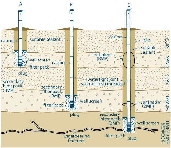
This figure is not to scale, it is for illustrative purposes for this technical bulletin only, and does not necessarily represent full compliance with other requirements found in the Wells Regulation.
The example on the left of the diagram (A) shows a test hole or dewatering well completed through a clay overburden into a sand overburden. The bottom of the well is completed with a well screen that is located in the sand overburden. A plug is located on the bottom of the well screen. A casing extends from the well screen to above the ground surface. The joints in the casing are watertight joints such as a flush threaded joint. A well cap is located at the top of the casing. There is a filled annular space around the well screen and casing. The bottom of the annular space around the well screen and lower casing in the sand overburden is filled with filter pack. A secondary filter pack is placed above the filter pack in the annular space around the casing located in lower portion of the clay overburden. The secondary filter pack is a best management practice (BMP) and not a requirement. The remaining annular space from the ground surface to the secondary filter pack is filled with suitable sealant.
The example in the centre of the diagram (B) shows a test hole or dewatering well completed through a clay overburden, sand overburden, a second clay overburden and into a gravel overburden. The bottom of the well is completed with a well screen that is located in the gravel overburden. A plug is located on the bottom of the well screen. A casing extends from the well screen to above the ground surface. The joints in the casing are watertight joints such as a flush threaded joint. A well cap is located at the top of the casing. There is a filled annular space around the well screen and casing. The bottom of the annular space around the well screen and lower casing in the gravel overburden is filled with filter pack. A secondary filter pack is placed above the filter pack in the annular space around the casing located in upper portion of the gravel overburden. The secondary filter pack is a best management practice (BMP) and not a requirement. The remaining annular space from the ground surface to the secondary filter pack is filled with suitable sealant.
The example on the right of the diagram (C) shows a test hole or dewatering well completed through a clay overburden, sand overburden, a second clay overburden, a gravel overburden and into water bearing fractures in a limestone bedrock. The bottom of the well is completed with a well screen that is located in the limestone bedrock. A plug is located on the bottom of the well screen. A casing extends from the well screen to above the ground surface. The joints in the casing are watertight joints such as a flush threaded joint. A well cap is located at the top of the casing. The casing is centred in the hole with two centralizers. The centralizers are a best management practice (BMP) and not a requirement. There is a filled annular space around the well screen and casing. The bottom of the annular space around the well screen and lower casing in the limestone bedrock is filled with filter pack. A secondary filter pack is placed above the filter pack in the annular space around the casing located in upper portion of the bedrock. The secondary filter pack is a best management practice (BMP) and not a requirement. The remaining annular space from the ground surface to the secondary filter pack is filled with suitable sealant.
There are four notes below the diagram.
Note 1 states bmp means best management practice.
Note 2 states the top of the filter pack around the well screen must be no closer than 2.5 metres (8.2 feet) below the ground surface.
Note 3 states the hole diameter must be at least 7.6 centimetres (3 inches) greater than the final outer diameter casing for at least 6 metres (19.7 feet) from the ground surface or the full depth of the well (whichever is less).
Note 4 states the hole must be large enough to allow for the installation of a tremie pipe in the annular space. The tremie pipe must be immersed in the rising accumulation of sealant in the annular space.
Figure 2: Example of Multi-Cased Bedrock Well Constructed by Drilling or Direct Push without Using a Driven Point (Not Scheduled to Be Abandoned within 180 Days after Completing Structural Stage)
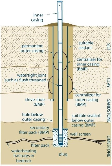
This figure is not to scale, it is for illustrative purposes for this technical bulletin only, and does not necessarily represent full compliance with other requirements found in the Wells Regulation.
The example in the diagram shows a test hole or dewatering well completed through a silt and clay overburden, sandstone bedrock and into water bearing fractures in a limestone bedrock. The bottom of the well is completed with a well screen that is located in the limestone bedrock. A plug is located on the bottom of the well screen. An inner casing extends from the well screen to above the ground surface. There is a permanent outer casing that extends around the inner casing from the ground surface into the sandstone bedrock. A drive show is attached to the bottom of the permanent outer casing. The joints in the casing are watertight joints such as a flush threaded joint. A well cap is located at the top of the inner casing. The casings are centred in the hole with centralizers. The centralizers are a best management practice (BMP) and not a requirement. There is a filled annular space around the well screen, inner casing and permanent outer casing. The bottom of the annular space around the well screen and lower casing in the limestone bedrock is filled with filter pack. A secondary filter pack is placed above the filter pack in the annular space around the inner casing located in upper portion of the bedrock. The secondary filter pack is a best management practice (BMP) and not a requirement. The remaining annular space around the inner casing from the ground surface to the secondary filter pack is filled with suitable sealant. The annular space around the permanent outer casing is filled with a suitable sealant.
There are three notes below the diagram.
Note 1 states bmp means best management practice.
Note 2 states see Chapter 6 of the Manual: Constructing the Hole, Casing and Covering the Test Hole or Dewatering Well for information on hole diameter. Filter pack material must be clean washed sand or gravel.
Note 3 states the annular space around the permanent outer casing must be filled with suitable sealant as described in Chapter 7 of the Manual: Annular Space and Sealing. The annular space between casings must be sealed as described in Chapter 7 of the Manual: Annular Space and Sealing. As a best management practice, the annular space below the permanent outer casing should be filled as described in best management practices in see Chapter 6: Constructing the Hole, Casing and Covering the Test Hole or Dewatering Well, Chapter 7: Annular Space and Sealing and Chapter 8: Multi-level Monitoring Test Holes in the Manual.
Figure 3: Examples of Directional Well Constructed by Drilling or Direct Push Without using a Driven Point (Not scheduled to be abandoned within 180 days after completing structural stage)
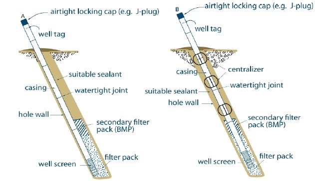
This figure is not to scale, it is for illustrative purposes for this technical bulletin only and does not necessarily represent full compliance with other requirements found in the Wells Regulation.
The example on the left of the diagram (A) shows a test hole or dewatering well angling from the left to the right below the ground surface into the subsurface. The bottom of the well is completed with a well screen. A plug is located on the bottom of the well screen. A casing extends from the well screen to above the ground surface. The joints in the casing are watertight joints such as a flush threaded joint. An airtight locking cap (e.g., J-plug) is located at the top of the casing. The casing and well screen are located near the left side of the hole. There is a filled annular space around the well screen and casing. There is a very small to nonexistent annular space on the left side of the hole compared to the right side of the annular space. The bottom of the annular space around the well screen and lower casing is filled with filter pack. A secondary filter pack is placed above the filter pack in the annular space around the casing. The secondary filter pack is a best management practice (BMP) and not a requirement. The remaining annular space from the ground surface to the secondary filter pack is filled with suitable sealant.
The example on the right of the diagram (B) shows a test hole or dewatering well angling from the left to the right below the ground surface into the subsurface. The bottom of the well is completed with a well screen. A plug is located on the bottom of the well screen. A casing extends from the well screen to above the ground surface. The joints in the casing are watertight joints such as a flush threaded joint. An airtight locking cap (e.g., J-plug) is located at the top of the casing. The casing is centred in the hole with three centralizers from the hole wall to the casing. The centralizers are a best management practice (BMP) and not a requirement. There is a filled annular space around the well screen and casing. The bottom of the annular space around the well screen and lower casing is filled with filter pack. A secondary filter pack is placed above the filter pack in the annular space around the casing. The secondary filter pack is a best management practice (BMP) and not a requirement. The remaining annular space from the ground surface to the secondary filter pack is filled with suitable sealant.
There are five notes below the diagram.
Note 1 states bmp means best management practice.
Note 2 states that it is important to use centralizers to centre the casing in the hole (see example B). A centred casing allows for the proper distribution of filter pack around the well screen and sealant around the casing. The absence of centralizers forces the casing and well screen to move to one side of the hole. This prevents the installation of filter pack around the well screen and the even placement of sealant around the casing (see example A). This can allow formation materials to plug the well screen and increase the risk of contaminant and foreign material migration along the side of the casing.
Note 3 states the top of the filter pack around the well screen must be no closer than 2.5 metres (8.2 feet) below the ground surface.
Note 4 states the hole diameter must be at least 7.6 centimetres (3 inches) greater than the final outer diameter casing for at least 6 metres (19.7 feet) from the ground surface or the full depth of the well (whichever is less).
Note 5 states the hole must be large enough to allow for the installation of a tremie pipe in the annular space.
Figure 4: Drilled Well in Overburden – Natural Development, Casing Pulled Back Exposing Screen Method (Not scheduled to be abandoned within 180 days after completing structural stage)
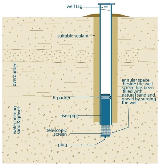
This figure is not to scale, it is for illustrative purposes for this technical bulletin only and does not necessarily represent full compliance with other requirements found in the Wells Regulation.
The example shows a test hole or dewatering well completed into a water bearing sand and gravel overburden. The bottom of the well is completed with a telescopic well screen that is located in the water bearing sand and gravel overburden. A plug is located on the bottom of the well screen. A riser pipe extends from the well screen that fits into an overlying casing. A k packer seals the lower portion of the inner casing to the riser pipe. The casing extends from just above the well screen to above the ground surface. A well cap is located at the top of the casing and a well tag is affixed to the casing above the ground surface. There is an annular space around the casing that has been filled with suitable sealant. During the pulling back of the casing to expose the well screen, the annular space beside the well screen has been filled with natural sand and gravel by surging the well. The ground surface beside the casing has been mounded to prevent the ponding of water in the vicinity of the well.
There are two notes below the diagram.
Note 1 states the hole diameter must be at least 7.6 centimetres (3 inches) greater than the final outer diameter casing for at least 6 metres (19.7 feet) from the ground surface or the full depth of the well (whichever is less).
Note 2 states if centralizers are used with rotary equipment or a breakaway guide is used with a cable tool equipment, the hole diameter must be at least 5.1 centimetres (2 inches) greater than the final outer diameter casing for at least 6 metres (19.7 feet) from the ground surface or the full depth of the well (whichever is less).
Figure 5: Example of Dug Test Hole (Not Scheduled to Be Abandoned within 180 Days after Completing Structural Stage)
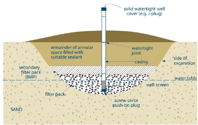
This figure is not to scale, it is for illustrative purposes for this technical bulletin only and does not necessarily represent full compliance with other requirements found in the Wells Regulation.
The example shows a dug test hole completed into a sand overburden below the water table. The bottom of the well is completed with a well screen that is located below the water table in the sand overburden. A screw-on or push-on plug is located on the bottom of the well screen. A casing extends from the well screen to above the ground surface. The joints in the casing are watertight joints such as a flush threaded joint. A solid watertight cover (e.g., J-plug) is located at the top of the casing. There is a filled annular space around the well screen and casing to the side of the excavation. The bottom of the annular space around the well screen and lower casing in the sand overburden is filled with filter pack. A secondary filter pack is placed above the filter pack in the annular space around the casing located in lower portion of the overburden. The secondary filter pack is a best management practice (BMP) and not a requirement. The remaining annular space from the ground surface to the secondary filter pack is filled with suitable sealant. The ground surface beside the casing has been mounded to prevent the ponding of water in the vicinity of the well.
There are three notes below the diagram.
Note 1 states bmp means best management practice.
Note 2 states the top of the sand, gravel or native materials around the well screen must not be closer than 2.5 metres (8.2 feet) below the ground surface.
Note 3 states the suitable sealant must be able to provide the sufficient structural strength to support the weight of persons and vehicles that may move over the area.
Figure 6: Example of Dewatering Well Constructed by Jetting with the Use of a Driven Point (Not Scheduled to Be Abandoned within 180 Days after Completing Structural Stage)
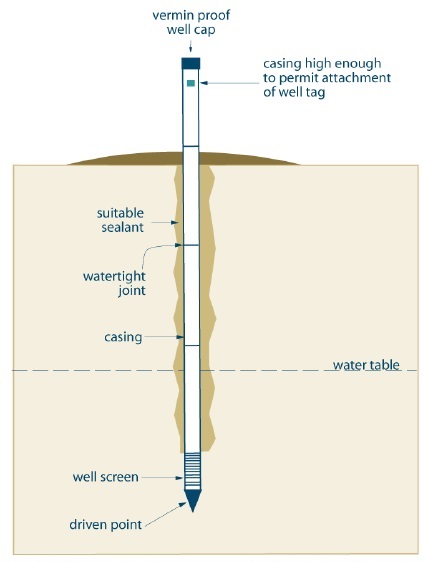
This figure is not to scale, it is for illustrative purposes for this technical bulletin only and does not necessarily represent full compliance with other requirements found in the Wells Regulation.
The example shows a jetted dewatering well completed into the subsurface below the water table. The bottom of the well is completed with a well screen that is located below the water table in the subsurface. A driven point is located on the bottom of the well screen. A casing extends from the well screen to above the ground surface. The joints in the casing are watertight joints such as a flush threaded joint. A vermin proof well cap is located at the top of the casing. The casing is extended high enough above the ground surface to allow for a well tag to be affixed to the casing. There is a filled annular space around the casing to the side of the excavation. The annular space from the ground surface to the bottom of the annular space is filled with suitable sealant. The ground surface beside the casing has been mounded to prevent the ponding of water in the vicinity of the well.
There is a note below the diagram. The note states in this example, the hole is constructed by the use of a jetting tool. After the hole has been completed, a drive point well screen with casing is placed in the hole. The person constructing the well by jetting must ensure that any annular space around the well casing is sealed to prevent any water, natural gas, contaminants, or other materials between subsurface formations (e.g., aquifers) or between a subsurface formation and the ground surface.
Figure 7: Example of Dewatering Well Constructed by Direct Push Equipment Using a Driven Point (Not Scheduled to Be Abandoned within 180 Days after Completing Structural Stage)
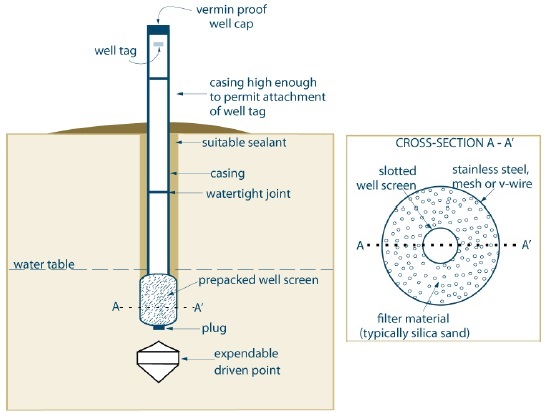
This figure is not to scale, it is for illustrative purposes for this technical bulletin only and does not necessarily represent full compliance with other requirements found in the Wells Regulation.
The example shows a driven dewatering well completed into the subsurface below the water table. The bottom of the well is completed with a pre-packed well screen that is located below the water table in the subsurface. A plug is located at the bottom of the pre-packed well screen. Below and not attached to the plug is an expendable driven point. A casing extends from the pre-packed well screen to above the ground surface. The joints in the casing are watertight joints. A vermin proof well cap is located at the top of the casing. The casing is extended high enough above the ground surface to allow for a well tag to be affixed to the casing. There is a filled annular space around the casing to the side of the excavation. The annular space from the ground surface to the bottom of the annular space is filled with suitable sealant. The ground surface beside the casing has been mounded to prevent the ponding of water in the vicinity of the well.
A dotted line extends horizontally from the term "a" which is located on the left side of the pre-packed well screen to the term " a' " which is located on the right side of the pre-packed well screen.
There are two notes below the diagram.
The first note states in this example, drive rods with a detachable (expendable) driven point were driven into the ground. A prepacked well screen with casing was installed into the drive rods. An annular space was created between the drive rods and casing. The annular space was filled with suitable sealant and the drive rods were removed.
The second note states since a driven point was used in the construction, materials and methods approved by the Director must be used to fill the annular space.
To the right of the two notes there is a second diagram that states "Cross-section A-A' ". This is a plan view looking down at the well. The diagram shows a circle representing the outside of the pre-packed well screen. A dotted line extends horizontally from the term "a" which is located on the left side of the pre-packed well screen to the term " a' " which is located on the right side of the pre-packed well screen. The outer portion of the pre-packed well screen is made of stainless steel, mesh or v-wire. The diagram also shows an inner circle that represents a slotted well screen. Between the two circles is a filter material, usually silica sand.
For information about Director’s approval for sealing methods see the: “Grout Placement – Annular Space for Driven Points” section in Chapter 7 of the Manual: Annular Space & Sealing.
Footnotes
- footnote[1] Back to paragraph A list of the seventeen technical bulletins is shown in the Additional Information Sources section near the end of this technical bulletin. on well issues created for a person who:
- footnote[2] Back to paragraph A “test hole” means a well that, (a) is made to test or to obtain information in respect of ground water or an aquifer, and (b) is not used or intended for use as a source of water for agriculture or human consumption, subsection 1(1) of the Wells Regulation, e-Laws website.
- footnote[3] Back to paragraph A “dewatering well” means a well that is not used or intended for use as a source of water for agriculture or human consumption and that is made, (a) to lower or control the level of ground water in the area of the well, or (b) to remove materials that may be in the ground water, subsection 1(1) of the Wells Regulation, Ontario Water Resources Act - Wells. constructed in the future, or
- footnote[4] Back to paragraph A well’s structural stage is complete on the day on which the well is capable of being used for the purpose for which it was constructed but for, (a) compliance with section 15; (b) the installation of a pump; or (c) any alterations necessary to accommodate pumping, monitoring, sampling, testing or water treatment equipment., the person constructing the well can, as an alternative, follow the requirements described in the Wells Regulation – Constructing New Test Holes & Dewatering Wells in Operation for No Longer Than 180 Days technical bulletin.
- footnote[5] Back to paragraph (DOI:10.1520/D5088-02R08) ASTM International, West Conshohocken, PA, ASTM website.
- footnote[6] Back to paragraph (DOI:10.1520/D5608-01R06) ASTM International, West Conshohocken, PA, ASTM website.
- footnote[7] Back to paragraph A “monitoring well” means a well that is a test hole as defined in Regulation 903 of the Revised Regulations of Ontario 1990 (Wells) made under the Ontario Water Resources Act, subsection 22(1) of Ontario Regulation 153/04 as amended made under the Environmental Protection Act, R.S.O. 1990, c. E. 19, Records of Site Condition — Part XV.1 of the act. in the Records of Site Condition regulation, see Chapter 2 of the Manual: Definitions & Clarifications, Table 2-2.
- footnote[8] Back to paragraph See the definition of Qualified Person in Chapter 2 Definitions and Clarifications of the Test Holes and Dewatering Wells – Requirements and Best Management Practices manual and section 5 of Ontario Regulation 153/04 as amended made under the Environmental Protection Act, R.S.O. 1990, c. E. 19, Records of Site Condition — Part XV.1 of the act. shall ensure that the phase two ESA is conducted in accordance with the requirements stated above.
- footnote[9] Back to paragraph Sections 36 to 50 of the Ontario Water Resources Act, R.S.O. 1990, c. O. 40, Ontario Water Resources Act..
- footnote[10] Back to paragraph Sections 36 to 50 of the Ontario Water Resources Act, R.S.O. 1990, c. O. 40, Ontario Water Resources Act. and
- footnote[11] Back to paragraph Ontario Regulation 153/04 as amended made under the Environmental Protection Act, R.S.O. 1990, c. E. 19, Ontario Water Resources Act..