Technical guideline for suspended access equipment on construction projects
If you are a designer, engineer, fabricator, owner or supplier of suspended access equipment (SAE), read this guideline to clarify the intent and meaning of Ontario Regulation 213/91, Construction Projects (the Construction Regulation) regarding suspended work platform systems and boatswain’s chairs.
Purpose of this guideline
This guideline is intended to assist designers, engineers, fabricators, owners and suppliers of suspended access equipment (SAE) by clarifying the intent and meaning of certain technical aspects of sections 136.1 to 142.06 applicable to suspended work platform systems and boatswain’s chairs found in Ontario Regulation 213/91, Construction Projects (the Construction Regulation) that came into effect on January 1, 2017. This guideline does not address general SAE user questions nor does it address questions relating to multi-point suspended work platforms. All references to specific regulatory provisions in this guideline are to the Construction Regulation unless otherwise stated.
This resource does not replace the Occupational Health and Safety Act (OHSA) and its regulations and should not be used as or considered legal advice. Health and safety inspectors apply and enforce these laws based on the facts they find in the workplace.
Regulated definitions
Certain new terms related to SAE have been defined in the Construction Regulation. Additional explanations have been provided here for the following definitions extracted from subsection 1(1) and from section 136.1, as the case may be, of the Construction Regulation.
Allowable suspended load
”Allowable suspended load” means the combined weight of a suspended work platform or boatswain’s chair, the hoisting device or devices, the rated platform capacity and the suspended portion of the suspension line or lines (section 136.1).
The term “allowable suspended load” includes hoisting devices, suspension lines and power cords and the “rated platform capacity” with the addition of the self-weight (dead load) of the suspended work platform or suspended work platform module(s).
Anchorage connector
“Anchorage connector” means a component or a system of components of a fixed support that secures a suspended work platform or boatswain’s chair and its associated suspension lines and lifelines to the fixed support (section 136.1).
The term “anchorage connector” refers to a specific component or system of components of a fixed support that includes, but is not limited to, anchors and baseplates with attached loops for use in both permanent and temporary “suspended work platform systems” (SWPS). The specific design requirements for an “anchorage connector” are stated in subsection 141.1(6).
The term “anchorage connector” should not be confused with the term “anchorage” as referenced in the CSA Z271-10 Standard. The Ministry of Labour, Immigration, Training and Skills Development interprets the term “anchorage” as referring to the substrate in which the “anchorage connector” is connected, such as but not limited to, a steel beam or concrete roof slab.
The Construction Regulation does not make a distinction between an “anchorage connector” used for tie-backs, for suspension lines or for lifelines. All are considered “anchorage connectors.”
Critical weld
“Critical weld” means, in relation to a suspended work platform, a weld the failure of which could result in the complete or partial collapse of the suspended work platform (subsection 1(1)).
All “critical welds” on structural components of a suspended work platform must be identified on the design drawing(s). If the design does not include any “critical welds” on structural components of a suspended work platform, then the non-destructive testing requirements prescribed in subsection 139.1(3) are not applicable.
The term partial collapse in the definition of “critical weld” refers to a non-catastrophic failure of a suspended work platform as a result of the failure of one or several critical welds located on components of the suspended work platform. The structural failure of a “critical weld” occurs when the load carrying capacity of the “critical weld” is diminished from that for which it is designed and the work platform can no longer support the rated capacity. The Ministry of Labour, Immigration, Training and Skills Development considers a partial collapse to be an event in which the suspended work platform moves unexpectedly due to a weld failure in a structural component.
A “critical weld” structural failure may be detected visibly or may only be detectable by non-destructive testing (defined below), thus the necessity of testing.
Fixed support
“Fixed support” means a permanent or temporary structure or a component of such a structure that can withstand all loads and forces the structure or component is intended to support or resist and is sufficient to protect a worker’s health and safety and includes equipment or devices that are securely fastened to the structure or component (subsection 1(1)).
The definition of a “fixed support” includes, but is not limited to, an “anchorage connector” which may include anchors, and a base plate with an attached loop etc. A “fixed support” also includes items such as outriggers and supporting structures but these items are not considered an “anchorage connector” (see Appendix A for a sketch).
A “fixed support” does not include any part of the suspension system such as the suspension line and associated components.
Generic installation drawing
“Generic installation drawing” means a drawing and related documentation, if any, that:
- identifies components, configurations and load limitations of a suspended work platform system or powered boatswain’s chair,
- is intended to be used at any location where all of the requirements in the drawing and documentation are satisfied, and
- bears the seal and signature of a professional engineer confirming that a suspended work platform system or boatswain’s chair installed in accordance with the drawing would be in compliance with the requirements of this Regulation (subsection 1(1)).
The requirement for a “generic installation drawing” is acceptable for installations and configurations of suspended work platform(s) (and powered boatswain’s chair(s)) that are designed by the manufacturer to work in common situations without modification from the manufacturer’s instructions. These common configurations must be included on a drawing, or in some cases drawings, and related documentation, sealed and signed by a professional engineer, which identifies the configurations, components and load limitations for their suspended work platform (or powered boatswain’s chair). The sealed and signed “generic installation drawing(s)” and related documentation must be kept at the project and made readily available to an inspector upon request.
While the “generic installation drawing” only applies to the installation of the platform or the boatswain’s chair, the employer must ensure that all other system components such as outriggers, anchorage connectors, suspension cables, etc. meet the appropriate regulatory requirements. Employers may wish to have supporting documentation that may be made available to an inspector upon request to assist in demonstrating compliance.
Professional engineer
“Professional engineer” means a person who is a professional engineer within the meaning of the Professional Engineers Act (subsection 1(1)).
A professional engineer is a person who holds a licence or temporary licence issued under the Professional Engineers Act to engage in the practice of professional engineering.
Rated platform capacity
“Rated platform capacity” means the combined weight of occupants, tools, equipment and other material that the manufacturer has indicated can be safely carried by a suspended work platform, work platform module or boatswain’s chair (subsection 1(1)).
The “rated platform capacity” for the modular configuration of a suspended work platform is determined by the manufacturer. The suspended work platform module configurations must be designed for a minimum “rated platform capacity” as prescribed in subsection 137.1(3).
The employer must ensure that the “rated platform capacity” is never exceeded (subsection 142.01 (5)) and should remember that the load carried by a work platform may not be constant. For example, when materials such as construction debris or abrasive blasting grit accumulate on a platform, they add to the load. The employer must remember to take the increased load from such materials into account when ensuring that the “rated platform capacity” is not exceeded.
The designers of the suspended work platform modules must ensure that all connections between suspended work platform modules are designed to transfer and withstand all loads that connections are expected to experience within the “rated platform capacity” (subsection 137.1(5)).
The “allowable suspended load” includes hoisting devices, suspension lines and power cords and the “rated platform capacity” with the addition of the self-weight (dead load) of the suspended work platform or suspended work platform module(s).
Site-specific installation drawing
“Site-specific installation drawing” means a drawing and related documentation, if any, that identifies components, configurations and load limitations of a suspended work platform system or powered boatswain’s chair for use at a specific site (subsection 1(1)).
A “site-specific installation drawing” will be required for suspended work platform systems when any one of the circumstances prescribed in subsection 141.6(3) apply, or if not all of the requirements in the “generic installation drawing” can be satisfied. Please note subsection 141.6(3) paragraph 6, which prescribes a “site-specific installation drawing” whenever shielding, tarpaulin, enclosure, sign or banner are used with a suspended work platform.
If a “site-specific installation drawing” is to be used, a professional engineer must prepare the drawing, inspect the installation for compliance with the site-specific installation drawing(s) before the suspended work platform system is put into service for the first time, and must write a report indicating whether the suspended work platform system has been installed in compliance with the drawing(s). The suspended work platform may not be put into service unless the professional engineer’s report indicates it has been installed in accordance with the site-specific installation drawing(s).
The sealed and signed “site-specific installation drawing(s)” and related documentation, and the professional engineer’s report must be kept at the project and made readily available to an inspector upon request.
Undefined terms
The provisions related to SAE in the Construction Regulation contain a number of terms in regards to suspended work platforms that are not defined but are referenced in the explanatory comments that follow in this guideline. For clarity, these undefined terms are explained before providing explanatory comments on the selected sections below.
Suspended work platform module and work platform module
“Work platform” and “suspended work platform system” are defined in section 136.1 and subsection 1(1) of the Construction Regulation, respectively, however; the terms “suspended work platform module” and “work platform module” are not defined. There are multiple references to these two terms in sections 137 to 142.06.
As defined in the Construction Regulation:
- “work platform” means a built or manufactured work surface that, as the context requires, is intended to be used as or is in use as the work area of a suspended work platform system, but does not include a boatswain’s chair (section 136.1).
- “suspended work platform system” means an access system comprising one or more overhead fixed supports, one or more suspension lines, hoisting devices, if any, and one or more work platforms that can be moved vertically, but it does not include a boatswain’s chair or a multi-point suspended work platform (subsection 1(1)).
The Construction Regulation recognizes that work platforms are not always constructed as one singular continuous structure, but may be made up of separate modules connected together. Therefore, the undefined terms “suspended work platform module” and “work platform module” are used in the Construction Regulation provisions related to SAE. These terms simply refer to “suspended work platforms” and “work platforms,” respectively, that are modular in nature and are not constructed as one singular continuous structure.
Selected sections relating to engineering matters
General design requirement — subsection 137(1)
As of January 1, 2017 all suspended work platform systems and powered boatswain’s chairs used on construction projects in the Province of Ontario must be designed by “professional engineers.”
For work platforms that were designed before January 1, 2017, a professional engineer must prepare a report that confirms that the structural integrity of the work platform is at least equal to the structural integrity of a work platform that is designed by a professional engineer and in accordance with the Construction Regulation (subsection 137.3(2)).
Suspended work platform system/powered boatswains’ chairs, design criteria — section 137
Subsection 137(6) prescribes the factored load combination that must be used in the design of the suspended work platform.
Clause 137(3)(b) and subsection 137(4) deal with design requirements for additional loads that may be applied on the suspended work platform system when it is in use, i.e., from wind or accumulation of materials. While these types of loads are accounted for in the design requirements, it remains the employer’s responsibility to ensure that the “rated platform capacity” is never exceeded (subsection 142.01(5)). In addition, if a work platform will be used that has any shielding, tarpaulin, enclosure, sign or banner on it that may increase the wind loads on the components of the suspended work platform system, a professional engineer must prepare a site-specific installation drawing (paragraph 6 of subsection 141.6(3) and section 141.8).
The intent of clause 137(3)(b) is to make sure that the suspended work platform’s “allowable suspended load” and the associated load applied on the suspended work platform system are not exceeded by the additional loads applied as set out in the CSA Standard Z271-10, clause 6.1.5. The phrase, “any other loads likely to be applied to it” refers to a site-specific installation where the professional engineer will account for additional loads on the suspended work platform system for the specific project.
Additional load allowance for debris or blasting grit — subsection 137.1(4)
The intent for subsection 137.1(4) is to address the additional construction debris loads that a suspended work platform may be subjected to depending on the work being conducted, such as but not limited to, concrete debris. The manufacturer provides the rated platform capacity for the suspended work platform. This capacity will include items such as the construction debris, tools, etc., and workers on the suspended work platform. Therefore, it is up to all workplace parties to make sure that the work being conducted on the platform does not exceed the manufacturer’s rated platform capacity and that the “allowable suspended load” of the suspended work platform system is not exceeded.
Work platform design drawing(s) requirements — section 137.2
Section 137.2 establishes requirements for the design drawing(s) of a “work platform.” Clause 137.3(6)(a) requires an employer to make the design drawing(s) available to an inspector upon request while the “work platform” is in use at the project; however, the ministry recognizes that a manufacturer may not provide the design drawing(s) to employers. As a result, the design drawing(s) of a “work platform” may not be located at the project.
The manufacturer may consider the design drawing(s) to be proprietary but this does not preclude the Ministry of Labour, Immigration, Training and Skills Development from requesting these documents when enforcing the legislation. The Ministry of Labour, Immigration, Training and Skills Development will work with employers to obtain the necessary information from the manufacturer as required. Under the Occupational Health and Safety Act, Ministry of Labour, Immigration, Training and Skills Development inspectors are required to maintain the confidentiality of proprietary information.
Work platform testing requirements — section 137.3
Subsection 137.3(2) requires a professional engineer to prepare a written report that confirms that the structural integrity of a work platform designed before January 1, 2017 is at least equal to the structural integrity of a work platform designed in accordance with sections 137 and 137.1.
Subsection 137.3(3) requires a professional engineer to prepare a written report which confirms that a work platform designed on or after January 1, 2017 meets the design requirements in sections 137 and 137.1, provides the results confirming that the ANSI/UL 1322-2004 testing requirements in clause 137.3(3)(b) are met and provides proof that the manufacturer has been certified to International Standard ISO 9001.
The ANSI/UL 1322-2004 testing results must be part of the report written by a professional engineer. The ANSI/UL 1322-2004 Standard is the version referenced in the Construction Regulation, as such; this is the version that must be used in the testing.
The intent of the term “worst case configuration” in clause 137.3(3)(b) is to make sure that the manufacturer tests the worst possible configuration, such that if this configuration passes then the other configurations will also pass without testing.
Clause 137.3(3)(d) requires a professional engineer to write a report that provides proof that the manufacturer of a suspended work platform or suspended work platform module has been certified to International Standard ISO 9001. If the manufacturer has not been certified to the International Standard ISO 9001, then the professional engineer must ensure that the requirements in subsection 137.3(4) are complied with and a quality assurance report is written.
Non-destructive testing (critical welds) — section 139.1
All critical welds used on the work platform must be identified on the design drawings, as prescribed in clause 137.2(d). “Non-destructive test” (NDT) means one of the below methods of testing or examining a material, component or part to evaluate its condition without subjecting it to physical distortion, damage or destruction.
Acceptable methods of non-destructive testing are:
- eddy current testing
- magnetic particle testing
- liquid penetrant testing
- radiographic testing
- ultrasonic testing.
Every non-destructive test must be carried out and interpreted by a person who has been certified by Natural Resources Canada to the appropriate level in accordance with CAN/CGSB Standard 48.9712-2014, Non-destructive Testing – Qualification and Certification of Personnel (subsection 1(1.1)). The person conducting the testing and writing the report is not required to be a professional engineer; however, they must meet the requirements stipulated in the CGSB Standard.
Non-destructive testing must be conducted at least on an annual basis, on a randomly selected representative sample of each structural component containing critical welds, as required in the Table (subsection 139.1(3)). Every supplier of and an employer who uses or owns a work platform must ensure that the non-destructive testing requirements are completed.
The structural components of a work platform are categorized into two groups, namely; Group 1 or Group 2:
- Group 1 — work platform trusses, corner or angled sections and platform modules
- Group 2 — work platform stirrups, module connectors and end frames.
The reason for having two groups is to divide the big components (Group 1) from the smaller components (Group 2) with regard to the number of structural components to be tested.
Non-destructive testing must be conducted on every critical weld on each of the structural components selected as part of the representative sample. The Table specifies how many representative samples must be tested based on the supplier or employer’s entire inventory of suspended work platforms.
Other parts of a suspended work platform not listed in Group 1 or Group 2 must be visually inspected for damage at least once within the 12-month period prior to being on a project and at least once annually while on the project (subsection 139.1(8)).
If a manufacturer indicates that there are no critical welds on structural components of the suspended work platform, then the non-destructive testing requirements prescribed in subsection 139.1(3) are not required.
Unique identifier, structural components — subsection 141(2)
The purpose of providing a unique identifier to specific structural components as prescribed in subsection 141(2) is to provide a means by which each specific structural component can be readily identified and distinguished for the purpose of tracking its history as recorded in the permanent equipment log prescribed in section 140. The equipment log must contain records of all inspections, tests, repairs, modifications and maintenance performed on the structural components of every work platform.
Fixed supports, design requirements — section 141.1
All fixed supports must be designed by a professional engineer. The professional engineer must design outriggers and supporting structures using the load factors prescribed in subsection 141.1(4) when calculating the factored resistance for the material being designed in conjunction with the Limit States Design methodology. The requirement prescribed in subsection 141.1(4) does not apply to anchorage connectors, which must be designed in accordance with subsection 141.1(6).
In addition, components that may be subject to overturning, such as but not limited to outriggers and supporting structures, must be designed and constructed to support at least four times the allowable suspended load or force as prescribed in subsection 141.1(5). The intent of this section is to provide a factor of safety against overturning for components that are susceptible to overturning. This is a stand-alone requirement for the stability of the system and not a factor of safety for the material properties of the components.
Anchorage connector, design requirement — subsection 141.1(6)
The definition for anchorage connector contained in section 136.1 is similar but not identical to the definition provided in the CSA Z271-10 Standard. The term “anchorage connector” is used in the Construction Regulation in order to clarify that the component or system of components that is the “anchorage connector” is part of a fixed support. A “fixed support” includes but is not limited to an “anchorage connector” where the term “anchorage connector” may include anchors and a base plate with an attached loop, etc. A “fixed support” also includes items such as outriggers and supporting structures but these items are not considered an “anchorage connector.”
A “fixed support” does not include any part of the suspension system such as the suspension line and associated components.
The term “anchorage connector” should not be confused with the term “anchorage” as referenced in the CSA Z271-10 Standard. The Ministry of Labour, Training and Skills Development interprets “anchorage” to refer to the substrate (e.g. a steel beam or concrete roof slab) in which the “anchorage connector” is connected.
An anchorage connector and its anchorage must be designed to resist the loads prescribed in subsection 141.1(6). However, if the span between adjacent points of suspension for the suspended work platform system exceeds 12 metres, the anchorage connector and its anchorage must be designed for the additional load on the anchorage connector or anchorage using the minimum live loads prescribed in subsection 137.1(3). The intent in this section is to make sure that the anchorage connectors and anchorage do not experience loads in excess of those allowed in subsection 141.1(6).
Appendix A contains a sketch of the components of a suspended work platform system.
Work platforms and components over 525 kg — paragraph 2 of 141.6(3)
Subsection 141.6(3) sets out specific circumstances where a site specific installation drawing is required. One circumstance that engages the requirement for a site specific drawing is if there will be a work platform, including its components, that weighs more than 525 kg as stated in paragraph 141.6(3)(2). This refers to the dead load of the suspended work platform and its components, which consist of the suspended work platform or suspend work platform module, hoists, suspension lines and power cord/boxes. For further clarity, hoists must be part of the dead load calculation.
Suspended access equipment hoisting device requirements — subsection 142.01(4)
The hoisting requirements in clause 8 of the CSA Standard Z271-10 must be met for all suspended work platform systems as prescribed in clause 142.01(4)(b).
Please note: Clause 8.4.6.8.1 of the CSA Standard requires that the capacity of a ground launched suspended work platform must be limited. The hoist must be limited so that it cannot lift more than 150% of its rated capacity. This can be accomplished by one of two means:
- The actual lifting capacity of the hoist must not be more than 150% of the rated capacity; or
- The hoist must be provided with an overload device that will prevent it from lifting if the actual suspended load exceeds 150% of the maximum allowable suspended load.
Suspended work platform hangers — subsection 142.06(5)
The intent of this section is to make sure that non-walk-through hangers (i.e. stirrups) which could be used by some manufacturers are not placed too close to, or too far from, the edge of the suspended work platform. Modular suspended work platforms that are designed with hangers on the ends may be in compliance with the Construction Regulation if the employer, owner or constructor can demonstrate compliance with the equivalency procedure in section 3 of the Construction Regulation.
Appendix A: Components of a typical suspended work platform system
The sketch shows components of a typical suspended work platform system. The sketch is for information only. Follow manufacturer’s instructions when using suspended work platforms.
A brief description of each component and the general location of the design requirements for that component in the Construction Regulation follows.
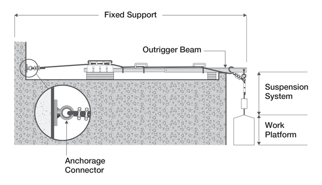
Anchorage connector
Includes base plate and eye loop (which is affixed to the anchorage) but does not include the tie-back rigging hardware. The design for the anchorage connector must be as prescribed in subsection 141.1(6). The anchorage connector falls under the definition for a fixed support.
Outrigger beam
The outrigger beam, associated counterweights and supporting structure if any, falls under the definition of a fixed support. The outrigger beam structure must be designed using the load factors prescribed in subsection 141.1(4) in conjunction with the Limit States Design methodology provisions in the Building Code. The design of the outrigger beam and if applicable, supporting structure must meet the requirements of subsection 141.1(5) for overturning.
Suspension system
The suspension system includes wire ropes, hoisting mechanism, rigging hardware as well as the tie-back wire rope and associated rigging hardware. The suspension system must comply with the requirements prescribed in section 142.01.
Work platform
The work platform includes the platform and support structures such as trusses, stirrups, modules and module connectors, corner or angled sections and end frames. The work platform design must meet the requirements of section 137, and section 137.1.
More information
- Infrastructure Health & Safety Association
- Workplace Safety & Insurance Board
- CSA standards (view only) referenced in occupational health and safety legislation
- Canadian General Standards Board
- Guidelines for multi-point suspended scaffolds
Call toll-free
Call toll-free
Call Monday to Friday 8:30 a.m. to 5 p.m. for general inquiries about workplace health and safety. Always call 911 in an emergency.