Part 3. Well drilling
Part 3. Well drilling
The following drilling standards apply to conventional rotary and cable-tool drilling techniques.
Where other publications are referenced within this Part, the reference shall be read as a reference to the most current edition of the publication in effect, including all published amendments.
3.1 General
The operator shall:
- ensure that all casing, tubing and equipment used in the drilling of a well is in good condition and adequate for the depths to be drilled and the pressures that may be encountered;
- plan and effect a casing and cementing program for the well to protect all fresh water horizons and all potential oil-bearing or gas-bearing horizons penetrated during drilling operations and to prevent the migration of oil, gas or water from one horizon to another;
- ensure that all fluid produced or recovered from a well during drilling operations is handled and disposed of in a manner that will not interfere with the rights of any person; and
- ensure that oil field fluid, oil, fuel or any flammable products and refuse from a well or used during the drilling of a well are not handled or disposed of so as to,
- create or constitute a hazard to public health or safety,
- run into or contaminate any fresh water horizon or body of water or remain in a place from which it might contaminate any fresh water or body of water, or
- run over or damage any land, road, building or structure.
3.1.1 Restricted drilling areas
No person shall drill a well having a surface location:
- within 50 meters of any high voltage power line, road allowance, railway, transmission pipeline or other utility right of way;
- within 75 meters of any dwelling, agricultural, commercial or industrial building, school, church or place of public assembly;
- on land, within 100 meters of the shoreline of any of the Great Lakes including the interconnecting waterways and 30 meters from any other lake, river, stream or municipal drain; and
- in the water covered areas of Lake Erie,
- within 800 meters of the shore-line, and
- within 800 meters of the International Boundary.
Note: Operators must comply with federal and municipal height and setback requirements for well locations on properties located adjacent to airports.
3.1.2 Drilling rig set backs
The location of the drilling and associated equipment used at the well site shall be spaced in accordance with the distances specified in Part 5.
3.1.3 Internal combustion / diesel engines
See Part 5, sections 5.5.4, 5.5.4.1, 5.5.4.2.
3.2 Drill sump / pit
Prior to spudding the operator shall:
- construct earthen sumps, reserve pits and mud circulation pits as required; or
- provide tanks for such purposes.
3.2.1 Sump / pit construction
Where earthen pits or sumps are constructed the operator shall:
- provide temporary fencing around the sump;
- install an impervious liner when:
- the depth to groundwater is within 2 metres of pit bottom, or
- where ground conditions are other than clay, and
- ensure that fluid levels do not rise above 0.5 metres below grade.
3.2.2 Sump / pit liners
Where liners are used in earthen sumps or pits:
- the liner shall be at least 20 mil (0.508 mm) thick virgin polyvinyl chloride or equivalent;
- the bottom and the sides of the pit shall be free of objects that could penetrate the liner;
- ample liner material shall be used to allow for sags and material loading to reduce stress on the liner;
- the bottom of the lined pit shall be weighted with earthen material or water before anchoring the ends of the liner on the surface or placing drilling mud in the pit; and
- where liners become torn, punctured or perforated the operator shall repair the liner in accordance with manufacturer’s recommended procedures or replace the liner.
3.3 Sump / pit closure
The operator shall close earthen sumps within six months of the TD date of the well.
3.4 Drilling program design
The operator shall ensure that the drilling program design:
- protects the public and the environment;
- permanently isolates and protects all potable water formations from contamination;
- isolates potential hydrocarbon-bearing formations from contamination caused by the migration of fluids from other permeable formations;
- prevents the migration of fluids between permeable formations and uncontrolled flow of fluids to surface or subsurface; and
- prevents shale and unconsolidated material from falling into the open hole during the drilling process.
3.5 Design of casing program
Casing design, for each stage of drilling operations, shall consider the following:
- the type of well service (e.g. sour, sweet, corrosive);
- the intended purpose of the well;
- the anticipated life span of the well;
- the location and flow characteristics of potential fresh water zones;
- the burst and collapse pressures that may be experienced during cementing operations on the casing string;
- the potential formation pressures that may be encountered during drilling operations and during subsequent production or injection operations;
- the tensile loading placed on the casing body and casing joints during running and cementing operations, especially if pipe is to be reciprocated;
- the pressure exerted on the inside of the casing during pressure integrity tests and formation stimulation operations;
- the need for corrosion allowance where corrosive formation fluids may be produced or may be in contact with the casing;
- the internal drift diameter of the casing relative to the outside diameter of the drill bit to be used in subsequent drilling operations;
- the reduction in casing joint strength due to bending forces in deviated or horizontal wells;
- the internal body wear on the casing string due to drill pipe rotation or cable movement during subsequent drilling operations, especially in deviated or horizontal wells;
- the temporary or permanent nature of the casing installation; and
- the plugging requirements of Part 11 and the method of plugging the well.
3.5.1 Casing removal
An operator shall not pull or strip a string of casing from a well, except where:
- provision is made for the removal of casing in the drilling program specified in the well licence application;
- casing is pulled and reset in the same formation to obtain a satisfactory casing seat;
- a well is plugged back or plugged to surface; or
- the annular space left open and the formation exposed by the pulling and stripping of casing is sealed.
3.5.1.1 Casing removal - producing wells
Where a well is a producing well, the operator shall ensure that:
- strings of casing intermediate between the producing casing and the surface casing are not recovered unless all horizons containing oil, gas or water are cemented off, and the surface casing is not recovered.
3.5.2 Hole size
For the purposes of proper sealing of a well, the hole size for a given casing shall be as follows:
| Casing Size (O.D. mm) | Hole Size (mm) Cable Tool Drilled Wells |
Hole Size(mm) Rotary Drilled Wells |
|---|---|---|
| Up to 177.8 O.D. | Casing O.D. + 16 | Casing O.D. + 38.1 |
| Greater than 177.8 O.D. | Casing O.D. + 33 | Casing O.D. + 50.8 |
| Greater than 273.05 O.D. | N/A | Casing O.D. + 76.2 |
3.5.3 Annular clearance
The operator shall design all well casing such that annular clearance between casings is not less than 12 mm for cable tool drilled wells and 25 mm for rotary drilled wells measured from the I.D. of the outer casing to the O.D. of the inner casing as shown below:

Cable tool
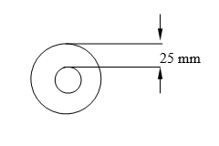
Rotary
3.6 Used casing
Where an operator proposes to install used casing in a well the operator shall:
- determine and record the history of used casing including the supplier or manufacturer, manufacturer’s specifications, and the previous application(s) of the casing;
- examine the condition of the threads on the pipe and inside the collars prior to use in the drilling operations;
- examine the condition of the pipe near the threads and near the casing collars to detect power tong damage and oval distortion;
- conduct spot casing wall thickness measurements on every joint of casing;
- conduct a hydrostatic pressure test to 110% of the maximum anticipated pressure during drilling, completion or production of the well to be held for 5 minutes;
- not install used casing that is greater than 20 years old; and
- provide for an Examiner to certify that all used casing has been inspected and tested in accordance with this section and is appropriate for its proposed use in the well.
3.7 Casing installation
The operator shall:
- guide casing into the hole using guide shoes, mule shoes, Texas shoes, or centralizers;
- apply the correct makeup torque or thread standoff for the casing;
- clean threads and examine casing on location prior to installation;
- examine for and clear all casing of internal obstructions;
- use thread compound on the casing joints; and
- pressure test the integrity of all joints in the string either prior to or during primary cementing operations.
3.8 API standards
Operators shall adhere to the following American Petroleum Institute (API) guidelines in the design and installation of intermediate and production casings:
- API Spec 5CT, Specifications for Casing and Tubing.
Note: This document lists chemical compositions, mechanical properties, testing requirements, and dimensional data for API certified casings. - API TR 5C3, Calculating Performance Properties of Pipe Used as Casing or Tubing.
Note: This document tabulates collapse and internal yield pressures, and joint strengths for API certified casings and tubing. - API RP 5A5, Field Inspection of New Casing, Tubing, and Plain end Drill Pipe.
Note: This document lists methods of field inspection of tubular goods. - API RP 5C1, Recommended Practice for Care and Use of Casing and Tubing.
Note: This document covers recommended procedures for transportation, storage, handling, reconditioning, and installation of casing and tubing. - API BUL 5C4, Bulletin on Round Thread Casing Joint Strength with Combined Internal Pressure and Bending.
3.9 Design of cementing program
The cementing program shall be designed in conjunction with the casing program to permanently prevent fluid migration between porous and permeable formations and shall protect all:
- potable water formations;
- potential hydrocarbon-bearing zones; and
- casings from all fluid bearing formations.
3.9.1. Design considerations
The operator shall consider the following when designing the cementing program:
- the effect of different lithologies in the well bore;
- the presence of soluble salts such as halite, sulphates such as anhydrite and gypsum, unconsolidated or fractured material, and sloughing shales;
- lost circulation zones;
- anticipated formation pressures;
- bottom hole temperatures;
- gas migration;
- corrosive formation fluids;
- quality and temperature of mix water;
- cement contamination by bore hole fluids;
- casing centralization;
- casing movement during cementing operations; and
- casing displacement.
3.9.2 Cement quality
The operator shall:
- meet API Spec 10A, Specification for Cements and Materials for Well Cementing;
- comply with API Spec 10A, Specification for Cements and Materials for Well Cementing, for selecting the correct cement grade and ensuring that the cement is mixed and pumped correctly; and
- provide an Examiner on site during all cementing operations including cement squeezes, remedial cementing, etc. to witness and certify that proper cementing practices were followed.
3.10 Conductor casing for shallow water
Conductor casing shall be run where water flows occur close to the surface.
3.10.1 Conductor casing for cable tool operations
The operator of a well being drilled using cable tool drilling equipment shall:
- ensure that conductor casing is of sufficient weight and quality to withstand driving force to the bedrock;
- after the conductor casing has been run, ensure the hole is bailed dry and monitored for at least 15 minutes to ensure the flow of fresh water has been shut off prior to the resumption of drilling;
- where the conductor casing has not stopped the water flow into the well bore, squeeze cement to isolate the fresh water zone(s); and
- not recover conductor casing prior to cementing in the next casing string.
3.11 Drilling surface hole - casing and cementing
Surface casing and cement shall:
- permanently isolate and protect all sources of potable water from other formations which contain non-potable fluids;
- prevent cross-flow between different fresh water aquifers or any fluid bearing zone;
- prevent the sloughing of unconsolidated material into the well bore; and
- be capable of anchoring the well control equipment.
3.11.1 Surface casing - cable tool drilled wells
Surface casing shall be cemented to the surface except where:
- there are no shows of water, hydrocarbons or brines in the open hole below the conductor casing;
- the conductor casing is not leaking;
- flows of hydrocarbon or artesian water are not expected in the next segment of the well; or
- one set of casing is cemented across all fresh water zones.
In the cases listed above, surface casing may be set on a casing shoe.
3.11.2 Surface casing - rotary drilled wells
The surface hole shall be drilled sufficiently deep into bedrock to:
- secure cemented casing to bedrock;
- be 15 metres into non-porous competent bedrock and 15 metres below the lowest potable water zone if that water is encountered in bedrock; or
- below all potable water zones yet above non-potable water zones if 15 metres is not available between the potable and non-potable water zones.
3.11.3 Artesian water
If artesian fresh water flow is expected in a well, a string of casing shall be run above the artesian fresh water zone so that the flow of water can be controlled. A second string shall be run and set below the artesian fresh water zone in order to isolate it from underlying porous formations containing non-potable fluids.
3.11.4 Surface casing cementing
Surface casing shall be cemented before formations containing non-potable fluids are drilled except where the requirements of section 3.11.1 are met for cable tool operations. Where surface casing is cemented it shall be:
- cemented full length from total depth to surface;
- using cement volumes based on caliper volume if available or theoretical annular hole volume plus the volume of the shoe joint plus;
- 50% excess cement if cement volume is based on theoretical calculation, or
- 20% excess if cement volume is based on a caliper volume; and
- cemented using the circulation method.
3.11.5 Cement monitoring
During the cementing operations, the annular flow shall be monitored for cement returns to surface. If the cementing operation does not obtain isolation of the fresh water, remedial cementing shall be done in accordance with section 3.13.12.
3.11.6 Cement quality
Surface casing cement shall be sulphate-resistant if sulphur-bearing fluids are anticipated in the next segment of a well. (Refer to API Spec 10A, Specification for Cements and Materials for Well Cementing and mill grind of cement to confirm sulphate resistance of cement.)
3.11.7 Cementing procedure
The surface casing cement shall be under-displaced to retain 5 metres of contaminated tail cement.
3.11.8 Pre-flush
If the surface hole is drilled using viscous drilling mud, a pre-flush shall be circulated to remove mud and filter cake before the surface casing is cemented.
3.11.9 Slurry samples
Slurry samples shall be obtained during the start, middle and end of the cementing operation to observe set-up time, curing time, and to estimate the compressive strength of the cement prior to drill-out.
3.11.10 Wait on Cement (WOC)
The operator shall collect cement samples while cementing and use them as a guide to determine sufficient WOC time. Drill-out operations shall not commence until the cement samples exhibit a compressive strength of 3600 kPa as determined by cement tables and visual examination.
3.11.11 Casing pressure test
A pressure test shall be conducted on the casing before the cement is drilled out of the shoe joint. If the casing fails the pressure test, the problem shall be identified and remedial work shall be undertaken before drilling operations are continued.
3.11.12 Pressure Integrity Test (PIT)
After the cement in the shoe joint and a maximum of 0.5 metre of new formation have been drilled, the operator shall conduct a PIT:
- using a low volume, high pressure pump and apply a pressure on the formation equivalent to a gradient of 18 kPa per metre but in no case shall the pressure applied be greater than pressure capable of forcing drill pipe out of the hole;
- for a duration of ten (10) minutes;
- using an incompressible fluid to apply the pressure for the test; and
- recording and retaining on file the following information:
- type of fluid used and its gradient (kPa/metre),
- test duration,
- initial pressure, and
- final pressure.
3.11.13 Pressure Integrity Test (PIT) failure
If the surface casing seat does not hold pressure, the operator shall rectify the problem before drilling operations are continued.
3.12 Drilling intermediate hole - casing and cementing
Intermediate casing and cement shall be used to:
- protect equipment and shallower formations from excessive pressures;
- permanently prevent fluid migration between porous and permeable formations;
- prevent the shales and unconsolidated material from falling into the open hole; and
- control the maximum anticipated target zone pressure.
3.12.1 First control string
The intermediate casing comprising the first control string shall be set and cemented prior to drilling into the target zone.
3.12.2 Aquifer present
Where an aquifer is present in the intermediate hole, the next string of casing shall be cemented in place.
Note: In many areas of Ontario more than one aquifer may be encountered in the intermediate hole.
3.12.3 Isolation
The operator shall:
- identify all oil, gas and fluid bearing zones during the drilling of a well;
- pump sufficient cement to separate all oil, gas and fluid bearing zones from each other and from the previous casing string;
- where more than one oil, gas or fluid bearing zones is present behind a string of casing, ensure that cement in the casing annulus rises 25 metres above the top of the oil, gas or fluid bearing zones that is encountered below the base of the previous casing; and
- where good cement returns are not received at surface, identify the top of cement in the casing annulus and provide for an Examiner to certify isolation of all porous zones.
3.12.4 Lost circulation
If lost circulation is expected or detected in the drilling of an intermediate hole, the operator shall take necessary measures to isolate the lost circulation zone from any other porous zone encountered in the drilling of the well by:
- sealing the zone prior to or during the cementing of the casing designed to cover the zone; or
- if a zone of lost circulation is identified during drilling operations, the operator may plug off this zone immediately.
3.12.5 Cementing
The intermediate casing shall be cemented by the circulation method with sufficient cement volume to theoretically reach to at least 25 metres above the casing seat of the previous casing string.
3.12.5.1 Cement monitoring
If the cementing operation does not obtain isolation of all porous zones, remedial cementing shall be done in accordance with section 3.13.12.
3.12.6 Cement volume
Cement volume shall be based on caliper volume if available or theoretical annular hole volume plus the volume of the shoe joint plus:
- 30% excess cement if cement volume is based on theoretical calculation; or
- 20% excess up to the designed cement top if cement volume is based on a caliper volume.
3.12.7 Cement quality
Intermediate casing cement shall be sulphate-resistant if sulphur water zones have been penetrated in the intermediate hole. (Refer to API Spec 10A, Specification for Cements and Materials for Well Cementing and the mill grind analysis of cement to confirm sulphate-resistance of cement).
3.12.8 Cementing - shoe joint
A shoe joint with a length of five metres shall be run to retain contaminated tail cement.
3.12.9 Wait on Cement (WOC)
WOC time shall be 6 hours. Drill-out operations shall not commence until the cement sample exhibits a compressive strength of 3600 kPa as determined by cement tables and visual examination.
3.12.10 Casing pressure test
A pressure test shall be conducted on the casing before the cement is drilled out of the shoe joint. The pressure test shall consist of:
- a low pressure test of usually 1400 kPa; and
- a high pressure test where the surface pressure for the high pressure test shall be 110% of the maximum anticipated formation pressure in the next segment of the well.
If the pressure test fails, the problem shall be identified and remedial work shall be undertaken before drilling operations are continued.
3.12.11 Pressure test - cable tool
For cable tool operations, the spool, casing valve and BOP equipment on the wellhead shall be installed and tested to a pressure specified in the drilling program in conjunction with the static pressure test on the intermediate casing string.
3.12.12 Pressure Integrity Test (PIT)
After the cement in the shoe joint and a maximum of one half-metre (0.5m) of new formation have been drilled, the operator shall conduct a PIT:
- using a low volume, high pressure pump;
- applying pressure on the formation at a pressure equivalent to a gradient of 18 kPa per metre or the expected reservoir pressure;
- for a duration of ten (10) minutes;
- using an incompressible fluid to apply the pressure for the test; and
- recording and retaining on file the following information:
- type of fluid and its gradient (kPa/metre),
- test duration,
- initial pressure, and
- final pressure.
3.13 Drilling main hole - casing and cementing
Cemented production casing shall protect equipment and formations from anticipated pressures and permanently prevent fluid migration between porous and permeable formations.
3.13.1 Logs for exploratory wells
Within 30 days of the well’s TD date, the operator of a well classed as exploratory shall run a:
- gamma ray log from the top of the bedrock to the TD; and
- a neutron log through the vertical and deviated sections of the wellbore from the top of the bedrock to the start of the horizontal section of the wellbore or TD, as the case may be.
3.13.2 Wellhead equipment – drilling
The operator shall ensure that all valves, nipples, casing and tubing spools, casing and tubing bowls, and changeover flanges and spools installed below the BOP on the wellhead after the last intermediate casing (or surface casing if no intermediate casing) has been installed, comply with API Spec 6A, Specification for Wellhead and Tree Equipment.
3.13.3 Blowout Prevention (BOP)
The Blowout Prevention (BOP) System for well control shall be installed in accordance with Part 4 and pressure-tested in conjunction with the pressure test of the last string of intermediate casing.
3.13.4 Cable Tool Well Control Equipment
- Prior to drilling of a formation with potential for the flow of natural gas or crude oil, a well control device shall be installed that is;
- capable of closing around the cable and on the open hole, and
- which can be controlled from a remote location;
- The well control device shall be function tested daily during the drilling operations.
- All the components of the lubricator system assembly shall be capable of handling at least 120% of the maximum anticipated pressure.
- The operator shall specify in the drilling program when a full lubricator system shall be employed.
- A full lubricator system shall be required when;
- gas is encountered with H2S content greater than 100 ppm,
- when crude oil flows to surface or is capable of unloading during bailing operations, or
- when flows of natural gas exceed 7.0 103m3/D (250 Mcfd).
3.13.5 Rotary well control equipment
Well control equipment in addition to the requirements under Part 4 shall be installed when drilling the well under balanced, with air, gas or foam. When a rotating head is installed as a part of this additional well control equipment, it shall be attached directly to the BOP system. The side outlet shall be equal to or larger than the connecting outlet.
3.13.6 Cementing
The top of the cement in the production casing annulus shall be placed inside the previous intermediate casing to a height of 25 metres above the intermediate casing seat; but in every case, not less than 100 metres above the highest potential pay zone. In the case of:
- a corrosive zone behind the intermediate casing that has not been covered with cement, the cement in the production casing annulus shall be sufficient to rise 25 metres above the top of the corrosive zone;
- liners being used, they shall be cemented across their full length;
- disposal and injection well casings, cement tops shall be as outlined in Part 7;
- a well located in a water covered area, the production casing shall be cemented to surface before production commences.
In all cases, the operator shall provide for an Examiner to certify cement tops.
3.13.6.1 Cement monitoring
If the cementing operation does not obtain isolation of all porous zones, remedial cementing shall be done in accordance with section 3.13.12.
3.13.7 Cement volume
Cement excess volume shall be:
- 30% if cement volume required is based on theoretical calculation; or
- 20% if cement volume is based on a caliper volume determination.
Note: Theoretical volume calculations shall include the volume of the shoe joint.
3.13.8 Cement quality
Cement quality across the potential pay zone shall be no less than the classification of neat cement without volume extenders, and:
- the water used to mix cement shall be of a quality and temperature required to achieve maximum compressive strength for the cement; and
- a casing shoe joint with a length of five metres shall be run to retain contaminated tail cement.
3.13.9 Cement placement
The operator shall place cement:
- by displacement with an appropriate wiper plug to separate the cement from the displacing fluid;
- with a float-type collar, a latch-down type collar, or a baffle plate run above the shoe joint so that a wiper plug can be used to provide a positive stop to cement displacement;
- using a preflush fluid or scavenger cement to remove the drilling fluid and the filter cake and to improve the cement bond before the tail cement is pumped into the casing for rotary drilling operations where viscous drilling fluids have caused filter cake build-up; and
- using wall cleaners or scratchers installed across the pay zone to improve the cement bond if viscous drilling fluid has caused filter cake build-up on the well bore.
3.13.10 Centralizers
Centralizers shall be run at 15 metres above the top and at the base of every porous formation and in no case at intervals greater than 100 metres within the cemented segment of the well.
3.13.11 Lightweight cement
Lightweight cements may be used to protect formations from excessive hydrostatic pressures and potential lost circulation under the following conditions:
- a sufficient volume of neat tail cement is pumped to place the top of the neat cement at least 50 metres above the uppermost hydrocarbon bearing formation; and
- the tail cement covering the potential pay zone is equal in quality to the classification of neat cement.
3.13.12 Remedial treatments/cementing
Remedial techniques shall be used to meet design considerations when unconsolidated formations, sloughing shale, lost circulation and other such conditions are encountered and if there is evidence of communication between permeable formations behind a casing string and where hydrostatic communication is suspected between porous formations.
3.13.13 Cement bond log
Where remedial cement squeeze treatment is required a cement bond log shall be run prior to a cement squeeze, to identify the problem, and after the cement squeeze operation, to confirm its effectiveness. The operator shall record and retain on file remedial cementing records including procedures, observations, and pressure test results in full detail.
3.14 Surface equipment
All valves, tubing and casing heads, and tubing and casing spools installed on the wellhead shall comply with API Spec 6A, Specification for Wellhead and Tree Equipment. For solution mining wells valves shall comply with API Spec 6A, Specification for Wellhead and Tree Equipment or CSA B51, Boiler, Pressure Vessel, and Pressure Piping Code. Prior to completing the well after the production casing has been set and cemented, the operator shall:
- install a casing head or spool with at least two valved and bull plugged side outlets to allow pack-off of the production casing and the intermediate casing annulus in the event that insufficient cement was pumped to isolate all main hole porous zones from the surface during the production casing cement job;
- provide a wellhead to isolate the annulus at the surface or isolate the potential flow of water down hole, if flows of water are possible from outside the intermediate casings; and
- for oil and gas wells where tubing is run in the well, install a tubing head or tubing spool with at least two, valved and bull plugged side outlets.
3.15 Drilling records
The operator shall record and keep on file the following casing information:
- the size, type, grade, and weight;
- the names of the manufacturer and supplier;
- a casing tally;
- whether the casing was new or used;
- the history of use for used casing;
- setting depth; and
- a description of any operational problems encountered while running the casing into the well including when casing is circulated and, or driven down.
3.16 Cementing records
The operator shall monitor, record, and retain on file indefinitely the following information pertaining to each cement job:
- name of the cementing company;
- cement blends used including cement type and additives;
- source of the mix water;
- type and volume of any preflush;
- volumes of cement;
- cement slurry density;
- actual displacement volume;
- final displacement pressure;
- any cement movement techniques;
- observation of cement returns including an estimation of the volume of cement returns;
- float equipment and casing attachments;
- results of every pressure test;
- cement tops and how they were identified e.g. by logging;
- a detailed description of any operational problems; and
- a copy of the cement bond logs.
3.17 Daily records
The operator shall ensure that daily records are kept at the well site during all drilling operations and these records shall include:
- the depth at the beginning of the day or shift;
- the depth at the end of the day or shift;
- the diameter of the hole;
- any change in the casing program;
- if casing is set, its setting depth, casing size, type, grade, weight and whether the casing is new or used;
- a description of all cement jobs performed;
- pressure tests and results;
- the depth at which any showing, however small, of oil, gas or water is encountered and the flows, pressures, and levels thereof;
- the depth or interval of lost circulation zones encountered; and
- a description of any related operations including fishing, stimulating, perforating, acidizing, fracturing, surveying and plugging.
3.18 Drill cutting and fluid samples
The operator, during the drilling of a well, shall:
- collect drill cutting samples from the:
- vertical or deviated portions of a well bore, taken at intervals not greater than 3 metres, from the top of bedrock to the total depth of the vertical or deviated portion of the wellbore; and
- horizontal portion of a well bore, taken at intervals not greater than 6 metres, from the end of the build section of the well to the total depth; and
- prepare the samples by:
- bagging, drying and accurately labeling the bags with the name of the well and licence number as it appears on the well licence and the corresponding depth interval; or
- washing, drying and placing in vials and accurately labeling the vials with the corresponding depth interval and the box of vials labeled with the name of the well and licence number as it appears on the well licence; and
- where the Ministry requests, collect samples of any oil, gas or water recovered from a well.
3.18.1 Reporting
The operator of a well being drilled shall comply with Part 13 for the reporting of the drilling activity notifications, completion information, drill and core samples, well tests and logs.
3.19 Site rehabilitation
Within six months of the end of every drilling or plugging operation, the operator shall:
- clear the area around the well of all refuse material;
- dispose of all liquid and solid waste in environmentally acceptable and safe manner;
- drain and fill in excavations;
- where the pits contain salt or other chemicals which may inhibit plant growth, clean out such pits before filling;
- remove concrete bases, machinery and materials;
- level and restore the site, as nearly as is possible, to its original condition prior to drilling; and
- provide for an Examiner to visit the site and certify that rehabilitation and plugging of the well was completed in accordance with this Standard.
3.20 Drilling in water covered areas
The operator of a well being drilled in a water covered area shall:
- for wells located in Lake Erie, not commence drilling operations prior to April 1st or after October 31st in any calendar year;
- cement all casings to lake bed;
- continuously monitor for the occurrence of oil and other liquid hydrocarbons;
- plug any well that encounters and is capable of producing appreciable amounts of oil or other liquid hydrocarbons;
- use only fresh water based drilling fluids;
- have onboard tanks to contain all drilling fluids and cuttings in the event that oil or liquid hydrocarbons are encountered and return all such materials to shore for proper disposal; and
- return drill cuttings that are not contaminated by liquid hydrocarbons to the lakebed in a manner that minimizes turbidity.
3.20.1 Emergency response plans
Operators conducting drilling and production operations in water covered areas shall prepare, implement and submit a copy of a contingency plan to the Ministry each year before commencing any offshore work. The plan shall include:
- Emergency definitions;
- Written instructions for response and mitigation actions to be taken for:
- accidents resulting in injury or fatality,
- oil, chemical, H2S or other fluid spill or gas release,
- fire or explosion,
- loss of well control,
- collision or near miss incident, and
- evacuation or abandon ship;
- Emergency response organization and corresponding responsibilities for actions to be taken.
- Locations and access routes or directions to all works.
- Listing and location of resources, personnel, supplies and equipment that are necessary to mobilize in the event of an incident described in item (b);
- Contact lists and priorities for all relevant company personnel, government agencies and equipment and material suppliers and locations; and
- Incident assessment and reporting procedures.
3.20.2 Emergency Response Drills
Emergency Response Drills shall be conducted on a regular basis to test the effectiveness of the Emergency Response Plan.