7. Completing the Well’s Structure
Chapter Description
This chapter covers the requirements for the finishing steps of new well construction. Some of the finishing steps include developing, venting, covering and securing the well. This chapter also covers affixing the well tag to a well.
There are other requirements and exemptions for finishing a new well that are not listed in this chapter because they do not relate to the structure of the well. For example a person constructing a well must complete and deliver a well record, show a water sample for visual examination, conduct a test of the well yield and disinfect a well. The well record and other requirements are covered in subsequent chapters.
Regulatory Requirements - Completing The Well’s Structure
Relevant Sections - The Wells Regulation
- Well Pit – Subsections 12(7), 12(8) and 12(9)
- Well Pit Casing – Subsection 13(14)
- Covering the Well – Section 12.2 and Subsections 15.2(6) to (8)
- Surface Drainage – Section 12.3
- Casing Height – Subsections 13(8), 13(9) and 13(10)
- Development – Section 14.8
- Development by Surging – Subsection 14.4(2), paragraph 1, i, B
- Well Tag – Section 14.11
- Venting – Subsection 15.1(1)
The Requirements - Plainly Stated
The Wells Regulation requires the following regarding the finishing steps of the construction of a new well:
Covering the Well
If the well is left unattended during construction, the person constructing the well must cover the upper open end of the well securely to prevent entry of surface water and other foreign materials (see Chapter 9: Equipment Installation for further information on well caps and covers).
Surface Drainage (Earth Mounding) around the Well:
The person constructing the well must ensure that the slope of the ground surface (surface drainage) is such that water will not collect or pond near the well. Preventing the collection or ponding of water can be ensured by properly mounding with earth around the well and outward from the well to direct surface water away from the well.
Casing Extent for New Wells in Overburden Aquifers
Unless exempted, a new well that obtains water from an overburden formation, must be cased:
- from the water intake zone,
- to at least 40 cm (16 inches) above the highest point on the ground surface within 3 m (10ft) radially from the outside of the casing after the land is properly mounded for surface drainage as measured on completion of the well’s structural stage.
Casing Extent for New Wells in Bedrock Aquifers
Unless exempted, a new well that obtains water from a bedrock formation, must be cased:
- from the bedrock,
- to at least 40 cm (16 inches) above the highest point on the ground surface within 3 m (10ft) radially from the outside of the casing after the land is properly mounded for surface drainage as measured on completion of the well’s structural stage.
Casing Height Exemption for New Driven Point or Jetted Point Wells
An exemption to the minimum casing height requirement of 40 cm (16 inches) above the ground surface exists if the new well is made by the use of a jetted point or driven point and it has a visible, permanent marker.
To qualify for this exemption:
- the casing must extend a sufficient height to permit the attachment of a well tag;
- the casing must be at least as high as the highest point on the ground surface within a 3 m (10ft) radius of the well’s casing after the ground surface is properly mounded with earth to direct surface drainage away from the well as measured on completion of the well’s structural stage; and
- the permanent marker must identify the location of the well and be visible at all times of the year.
Well Pits
A new well must not be constructed with a well pit unless the new well is created by diamond drilling equipment in connection with mineral exploration.
A well pit must not be added to an existing well unless the existing well was created by diamond drilling equipment in connection with mineral exploration.
If a new drilled well is constructed with a well pit, the top of the casing of the drilled well must be at least 40 cm (16 inches) above the floor of the well pit and the well pit must be cased:
- from the bottom of the well pit,
- to at least 40 cm (16 inches) above the highest point on the ground surface within 3 m (10ft) radially from the outside of the well pit casing after the land is properly mounded for surface drainage as measured at the time the well pit is completed.
Reminder: All new well pits are banned in Ontario except for wells constructed by diamond drilling equipment that are also used in connection with mineral exploration. For further information on well pit installation see Chapter 9: Equipment Installation.
Well Caps or Covers
Dug or Bored
The top of the casing of a well that is constructed by digging or boring must be covered with a solid, watertight well cover, so that surface water and other foreign materials cannot enter into the well.
Drilled or Other
The top of the casing of a well that is not constructed by digging or boring must be sealed with a commercially manufactured vermin-proof well cap (this includes a properly installed and sealed sanitary well seal and a watertight and airtight well cap for a point well).
Exceptions to Well Cap or Cover Requirements
The cover, cap or seal is not required if all of the following criteria are met:
- A floor has been constructed around or adjacent to the casing of the well.
- A pump (including associated pump equipment such as a waterline connected to a pump) is installed above or adjacent to the well.
- The top of the casing is shielded in a manner sufficient to prevent the entry of any material that may impair the quality of the water in the well.
- The casing of the well is extended to at least 15 cm (6 inches) above the floor that has been constructed around or adjacent to the casing of the well.
Reminder: See Chapter 9: Equipment Installation for further information on well caps and covers.
Developing the Well
Before the structural stage of a new well is completed, debris (such as well cuttings, drilling fluids, etc.) must be removed from the well by developing the well until the well water is clear and free of sand.
For any new well, other than a well constructed by digging or by the use of a jetted or driven point, where a well screen is installed, the well must be developed after the placement of suitable sealant, using a surging method to remove fine grained soils.
Reminder: See definition of the “well’s structural stage” in Chapter 2: Definitions and Clarifications, Table 2-1
Venting
When a new well is constructed, the well must be vented to the outside atmosphere in a manner that will safely disperse all gases unless the casing is used to transmit water out of the well.
Additional venting requirements may apply after pumping equipment is installed in the well.
Reminder: See Chapter 9: Equipment Installation for further information on venting.
Well Tags:
Before the structural stage of a new cased well is completed, a well tag from the Ministry must be obtained and affixed permanently to the outside of the casing, or to a permanent structure associated with the well. The affixed well tag must be visible and not hidden by the well cap, any other components of the well or equipment associated with the well.
If an alteration, other than a minor alteration, is made to a cased well that does not already have a well tag, a well tag from the Ministry must be obtained and affixed before the alteration is completed as per the first paragraph of this section.
If a cased well that already has a well tag is altered, the well tag must be safeguarded during the alteration. If the well tag is removed before the alteration is completed, it must be reaffixed as per the first paragraph of this section.
If a broken, defaced, illegible or otherwise unusable well tag is encountered when altering the well, including a minor alteration, the person altering the well must:
- obtain a new well tag from the Ministry and, before the alteration is completed, affix it as per the first paragraph of this section, and
- return the original well tag and a completed well record with respect to the replacement of the well tag to the Director within 30 days after the new well tag is affixed to the casing.
Reminder: For more information on well tags, see Chapter 13: Well Records, Documentation, Reporting & Tagging.
Relevant Sections - Additional Regulations Or Legislation
- Ontario Water Resources Act, R.S.O. 1990, Chapter O.40 – Subsection 30(1)
- Environmental Protection Act, R.S.O. 1990, Chapter E.19 – Subsection 14(1)
Well Record - Relevant Sections - Completing Construction
Figure 7-1: Well Record - Relevant Sections
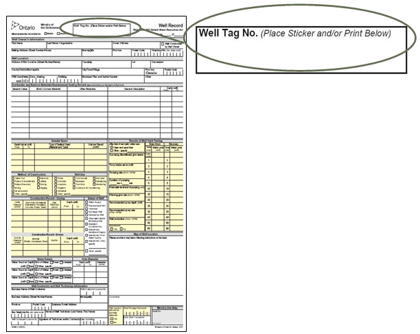
Figure 7-1 shows a sample of the details to be completed on the well record with regards to completing the well.
Key Concepts
What To Consider When Completing The Well’s Structure
Purpose Of The Well
When completing the well’s structure, it is important to consider the reason for the well installation. The well’s purpose will impact how the structure should be completed. For example, a municipal well may have to be installed in a pump house without a well cover.
Well Development
The purpose of well development is to remove any water or drilling fluids introduced into the well during drilling, stabilize the filter pack and formation materials opposite the well screen, minimize the amount of fine-grained sediment entering the well; and improve well efficiency and inflow of water into the well. Granular material (e.g., sand and silt) in the well water may have serious implications for the well owner’s pumping equipment, waterline and plumbing.
Casing Height And Mounding
A sufficient height of casing above the ground surface, or above the floor of a well pit, helps to prevent the entry of surface water or foreign materials through the top of the well. In addition, mounding earth immediately around the casing helps to direct surface drainage away from the well to reduce the risk of surface water ponding at the well site and to reduce the potential for surface water to migrate down the side of the well casing into the well.
Well Caps, Covers and Securing The Well
Securing and covering the casing are the primary safeguards against unauthorized entry into the well, vandalism or tampering. Well caps and covers also protect against the movement of surface water or foreign materials from the surface into the well. Securing the well includes ensuring that the well cap, seal or cover is on properly and may include the use of a protective cover with locking cap, barriers or fences.
Well Tag (Identification)
Well identification numbers link wells in the field with written records. The Ministry issues alphanumeric well tags that must be affixed to all new wells and many altered wells. The well tag will link the well or the well cluster to a corresponding well record. A well tag or number is important as it links detailed information of the construction process and design of the well. This information is crucial to persons who have to:
- locate wells in the field,
- test and sample, or
- maintain, or if necessary, alter or abandon a well.
Well Development
Well development has four broad objectives:
- To remove any water or drilling fluids introduced and fine materials disturbed during the construction of the well in order to obtain representative groundwater information and sediment-free water samples. In addition, this will minimize the potential for damaging pump equipment.
- To correct damage to the hole wall and adjacent native geological material caused during construction. This creates natural physical aquifer conditions to help determine hydraulic parameters such as hydraulic conductivity (K).
- To stabilize the filter pack and formation materials opposite the well screen. Development creates a graded zone (i.e., natural sand and/or gravel pack with larger to smaller material away from the water intake zone) around the well screen in an overburden well (see Figure 7-2).
- To maximize the efficiency of the well and hydraulic connection between the well intake zone and the formation by decreasing the potential for lower porosity and permeability near and at the well intake
footnote 1 .
These objectives are accomplished by applying some form of energy to the formation beside or below the well intake.
The Wells Regulation indicates that before the structural stage of a new well is completed, the person constructing the well must do everything reasonably practicable to remove any debris, including well cuttings and drilling fluids, from the well by developing the well until the well water is clear and free of sand.
Also, for any new well, other than a well constructed by digging or by the use of a jetted or driven point, where a well screen is installed, the well must be developed after the placement of suitable sealant, using a surging method to remove fine grained soils.
- Clear
- means all debris, including well cuttings and drilling fluids, has been removed from the well and well water; and the water is transparent or unclouded.
Reminder: “Clear” does not mean without any naturally occurring colour associated with the well water. For example, groundwater can turn an orange colour where naturally occurring iron is present in the groundwater and formation. Groundwater can turn a black colour where naturally occurring iron sulphide is associated with the groundwater. Both these samples could be “clear” for the purpose of well development requirements in the Wells Regulation.
Best Management Practice – Well Development
If all reasonable steps have been taken to develop the new well and it continues to produce water that visually has naturally occurring colour or sediment, drill cuttings or drilling fluids, the person constructing the well should notify the well purchaser and owner of the land that the condition exists to determine what next steps are necessary. With this information, the well purchaser and well owner can take the appropriate precautionary steps in designing, purchasing and installing pumping and treatment equipment in the well and water distribution system, or, if necessary, in properly abandoning the well.
Benefits Of Well Development
In general, development procedures have the following beneficial purposes:
- Protecting the pumping equipment, waterline and plumbing from damage due to granular material (e.g., sand and silt) in the well water.
- Reducing the compaction and intermixing of grain sizes produced during construction by removing fine material from the pore space.
- Increasing the natural porosity and permeability of the formation near the well intake by removing the finer grain material.
Specific To Drilled Wells:
Well Development:
- removes the filter cake, or drilling fluid film that coats the hole, and removes much or all of the drilling fluid and natural formation solids that have invaded the formation during well construction,
- creates a graded zone (e.g., natural sand or gravel pack larger to smaller material) around the screen in an overburden well, so that the well yields sand-free water (see Figure 7-2), and
- dislodges drill cuttings that may be plugging water bearing fractures in bedrock wells.
Figure 7-2: A Properly Developed Overburden Drilled Well
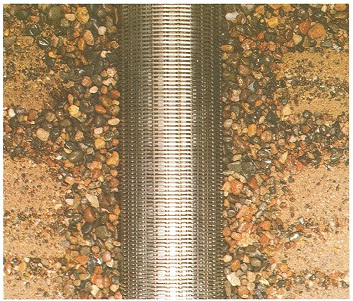
Figure 7-2 shows how development (by surging water back and forth) has created a graded zone (i.e., natural sand or gravel pack with larger to smaller material away from the water intake zone) around the well screen in an overburden well.
Development Methods
There are many different factors that contribute to the method chosen to develop a well.
The selection of the appropriate development methods from those listed below must be based on:
- equipment available and accessibility to the well,
- geology and hydrogeology (depth of aquifer in relation to well screen),
- well construction system and method used (cutting action used, flushing media),
- type of well installation (e.g., casing, annular space),
- diameter and depth of the well,
- diameter, slot size and length of the well screen and the filter pack,
- hydraulic characteristics of the well (e.g., static water level),
- health and safety requirements for field staff,
- types of contaminants and proper disposal of discharge water, and
- Permit To Take Water, discharge approvals and other regulatory requirements
Well Development Techniques
Below is a list of some methods of well development for various scenarios. In some cases multiple techniques may be used to develop a well. The methods include:
- surging or washing/backwashing with plunger devices (forcing water to flow in and out of a well screen by operating a plunger up and down in the well),
- air lift development (using an air lift to alternately surge and pump the well),
- air burst development (a combination of pumping with air and using large bursts of air injected into the well screen or bedrock hole to surge the formation),
- manual development (using a inertial lift pump),
- jetting (the use of high velocity jetting tools),
- over-pumping with a submersible pump (a combination of pumping with air and using large bursts of air injected into the well screen or bedrock hole to surge the formation),
- bailer surging, and
- hydrofracturing (hydrofracing) (bedrock well only).,
The Wells Regulation - Any water introduced into the well during development or other well construction must not impair the quality of any well water or cause an adverse effect on the natural environment.
Reminder: The container used to transport any water brought to the site for the well development must not contaminate the water in the container.
Surging
Surging is the simplest and the most common method of development. The clay, silt and sand grains are agitated by rapidly moving a plunger up and down in the well. This action moves the water in and out of the formation and well screen as shown in Figure 7-3. Water containing fine granular material moves into the well casing. The granules tend to settle to the bottom of the well so they can be removed by pumping water or air or bailing.
Figure 7-3: Surging
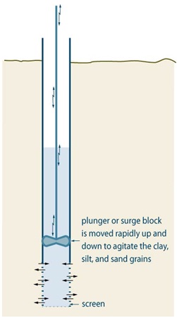
Reminder: This figure is not to scale, it is for illustrative purposes for this chapter only, and does not necessarily represent full compliance with other requirements found in the Wells Regulation.
Air-Lift Pumping
Another method available for developing a well is pumping with an air-lift pump at a high rate for a brief period, to draw water and formation fines into the well. Then the pump is shut off to “slug” the well, loosening formation fines, and breaking sand bridges in the formation and filter pack.
Reminder: Further information on well development can be found in Groundwater and Wells: Third Edition
Casing Height And Mounding
Surface Drainage(Mounding)
Mounding earth immediately around the casing to direct surface water away from the well helps to reduce the risk of surface water ponding at the well site and to reduce the potential for surface water to migrate down the side of the well casing into the well.
The Wells Regulation - The person constructing the well must ensure that the surface drainage is such that water will not collect or pond in the vicinity of the well.
Best Management Practice – Mounding
To prevent the pooling of water around the well, the following should be considered:
- In areas subject to frost heave, a soil or bentonite/sand layer should be placed adjacent to the casing and sloped to direct water drainage away from the well.
- In areas not subject to frost heave (e.g., in a heated pump house), a concrete pad should be installed and sloped slightly to direct water drainage away from the well.
Casing Height
The casing height must be checked at the completion of the well’s structure to ensure it complies with the Wells Regulation.
The Wells Regulations - Unless exempt, for any new well, the casing height must be at least 40 cm (16 inches) above the highest point within a 3 m (10ft) radius of the well’s casing after the ground surface is properly mounded with earth to direct surface drainage away from the well as measured on completion of the well’s structural stage. Figure 7-4 illustrates these measurements.
Reminder: There are exemptions to the above well casing height requirement for a new well constructed by the use of a driven point or jetted point or with a well pit. See “Casing Height for New Point Wells Constructed by Driving or Jetting” of this chapter and Chapter 9: Equipment Installation, “Well Pit Floor” section for further information.
The Wells Regulation - If an existing well casing extends to a height of 40 cm (16 inches) or more above the ground surface, the height of the casing cannot be reduced to a height of less than 40 cm (16 inches) above the ground surface. This includes cutting the casing or increasing the elevation of the ground surface adjacent to the well. Therefore, persons who work on pumps and equipment in a well, developers, general contractors, landscapers and well owners should be aware of the minimum height of the well casing requirement above the land surface. If the ground surface is raised, then the owner of the land or a properly licensed person working on the well must extend the well casing to the minimum required height.
Reminder: If work must be performed to raise the well casing, the person hired to do the work must have, or work for a business that has, a valid well contractor licence and have the proper prescribed class of well technician licence. See Chapter 3: Well Contractors & Well Technicians – Licences, Responsibilities & Exemptions for further information.
Figure 7-4: How to Measure Casing Height Above The Ground Surface For A New Well (Other Than A Well Constructed By The Use Of A Jetted Point And/Or Driven Point With A Permanent Visible Marker Identifying The Well)
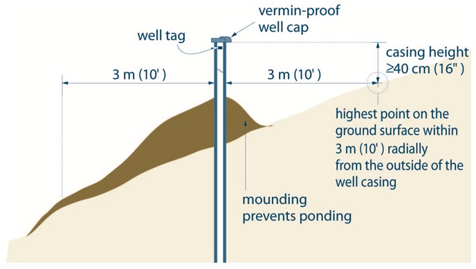
Reminder: The same method of measuring casing height applies to new jetted and driven point wells that have been constructed with a permanent visible marker. In that case, the casing must extend a sufficient height to permit the attachment of the well tag and be at least as high as the highest point on the ground surface within 3 m (10ft) radially from the outside of the well casing.
Reminder: This figure is not to scale, it is for illustrative purposes for this chapter only, and does not necessarily represent full compliance with other requirements found in the Wells Regulation.
Casing Height When Multiple Casing Are Used In A Well
In some cases, multiple casings of different diameters are installed in a well to reach a water producing zone. This type of installation is common in municipal wells, some flowing wells and other large water taking wells. For example the initial 20 m (65ft) of the hole may have a 40 cm (16 inches) diameter casing. The next 20 m (65ft) of the hole has a 30 cm (12 inches) diameter casing. Unless exempt, at least one of the casings has to meet the height requirements in the Wells Regulation.
The Wells Regulation - In the case of a multi-level well with an outer permanent casing and multiple inner casings:
- all casing extending from well screens must meet the height requirements in the Wells Regulation as described in the “Plainly Stated” section of this chapter, or
- the outer permanent casing must meet the height requirements in the Wells Regulation as described in the “Plainly Stated” section of this chapter.
Reminder: See Chapter 5: Constructing the Hole, Casing & Covering the Well.
Casing Height for New Point Wells Constructed by Driving or Jetting
The Wells Regulation - An exemption to the minimum casing height requirement of 40 cm (16 inches) above the ground surface exists if the new well is made by the use of a jetted point or driven point, and it has a visible, permanent marker.
In these cases, the casing must:
- extend a sufficient height to permit the attachment of a well tag, and
- be at least as high as the highest point on the ground surface within a 3 m (10ft) radius of the well’s casing for any new well after ground surface is properly mounded with earth to direct surface drainage away from the well as measured on completion of the well’s structural stage.
The permanent marker must also identify the location of the well and be visible at all times of the year.
Best Management Practice – Casing Height
Where feasible, casing height for a well should go beyond the minimum casing height requirements, particularly in an area prone to flooding, such as a flood plain. This will also allow for easier maintenance and identification purposes. Wells especially for driven and jetted point wells.
Special casing height considerations may have to be taken to vent gas from a well safely and keep the top of the casing above the top of the static water level in a flowing well.
To ensure a sufficient height of casing above the ground surface, it is also important to consider the proposed final grade of the property after landscaping.
When extending the casing of a jetted or driven point well above the ground surface, the person constructing a point well should take the necessary steps in the design and installation to prevent water from freezing within the point well system.
Well Covers And Securing The Well
Covering The Well
The Wells Regulation requires that if the well is left unattended during construction, the person constructing the well must cover the upper open end of the well securely in a manner sufficient to prevent the entry of surface water and other foreign materials
Reminder: See Chapter 9: Equipment Installation for further information on well caps and covers.
Dug Or Bored
The Wells Regulation - The top of the casing of a well that is constructed by digging or boring must be covered by the person constructing the well with a solid, watertight well cover sufficient to prevent the entry of surface water and other foreign materials into the well.
Reminder: A flat cover with an access lid embedded in the cover is not considered to be watertight. A well cover, such as a one piece solid concrete well cover, is considered to be solid and watertight if it is constructed and installed in a manner sufficient to prevent the entry of surface water and other foreign materials into the well. For clarification on the term “watertight” see Table 2-3 of Chapter 2: Definitions & Clarifications.
Reminder: See Chapter 9: Equipment Installation for graphics and further details on caps and covers.
Drilled Or Other
The Wells Regulation - The top of the casing of a well that is not constructed by digging or boring must be sealed by the person constructing the well with a commercially manufactured vermin-proof well cap. This includes a properly installed and sealed sanitary well seal commonly used in wells located in well pits and pump houses. This also includes a watertight and airtight well cap for a well that is constructed with the use of a well point.
Reminder: See Chapter 9: Equipment Installation for graphics and further details on caps and covers.
Well Cap Exemptions For Drilled Or Other
The Wells Regulation - Every well, other than a dug or bored well must be fitted with a commercially manufactured vermin-proof well cap, unless all of the following criteria are satisfied:
- a floor has been constructed around or adjacent to the casing of the well,
- the casing of the well is extended to at least 15 cm (6 inches) above the floor that has been constructed around or adjacent to the casing of the well,
- a pump is installed above or adjacent to the well, and
- the top of the casing is shielded in a manner sufficient to prevent entry of any material that may impair the quality of the water in the well.
Reminder: See Chapter 9: Equipment Installation for graphics and further details on caps and covers.
Venting The Well
The Wells Regulation - When constructing a new well, the person constructing the well must ensure that the well is vented to the outside atmosphere so that all gases will safely disperse from the well. Additional venting requirements may apply after pumping equipment is installed in the well.
The purpose of the vent is to allow the well to breathe, which enables pressures to equalize (e.g., when water is drawn out, air can enter the well keeping the column of water at atmospheric pressure). The vent also allows for the dispersal of natural gases to the outside atmosphere. In many cases, a properly designed vent is required to be installed on a well to safely disperse a gas that is poisonous, explosive or otherwise hazardous.
Reminder: See Chapter 12: Equipment Installation for additional information on venting requirements.
Figure 7-5: Watertight Cap With Screened Air Vent Above The Well Cap
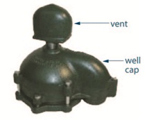
When the vent is attached to the top of a well cap as shown in Figure 7-5 the vent can be extended a significant distance above the well cap to safely disperse any explosive or poisonous gases. This type of system can also elevate the vent above potential flood elevations to reduce the risk of flood waters entering the well through the vent.
Special Considerations For Venting
Flowing Wells
Flowing wells are not exempt from the regulatory requirement for venting unless the casing is used in some way to transmit water out of the well.
A mechanical or inflatable packer, with a valve to allow air into and out of the well during pumping, may be installed to vent the well.
The Wells Regulation - Where a well is constructed and natural gas is encountered, the person constructing the well must notify the well purchaser, the owner of the land, and the Director that the condition exists.
If a well is producing a natural gas or other gas, the well owner must:
- take the necessary steps to manage the gas in a way that prevents any potential hazards,
- properly abandon the well, or
- seek the written consent from the Director to allow for the continued use of the well.
Reminder: Special precautions and procedures will be important when constructing wells and where gases are expected. Gases will need to be managed in a manner sufficient to prevent hazards. See the “Encountering Gas, Contamination and Water Quality” section of Chapter 5: Constructing the Hole, Casing & Covering the Well for further information and best management practices dealing with natural gas.
Well Tags
The Wells Regulation requires that, before the structural stage of a new cased well is completed, a well tag from the Ministry be obtained and affixed permanently to the outside of the casing or to a permanent structure associated with the well. The affixed well tag must be visible and not hidden by the well cap and any other components or equipment associated with the well.
The Wells Regulation - If an alteration, other than a minor alteration, is made to a cased well without a well tag, the person making the alteration must obtain and affix a Ministry well tag as described above, before the alteration is completed.
The Wells Regulation - If a cased well that already has a well tag is altered, the well tag must be safeguarded during the alteration. If the well tag is removed before the alteration is completed, it must be reaffixed, as described above.
The Wells Regulation - If an alteration, including a minor alteration, is made to a well with a well tag that is broken, defaced, illegible or otherwise unusable the person making the alteration must:
- obtain a new well tag from the Ministry and, before the alteration is completed, affix it to the well casing or a structure associated with the well, and
- return the original well tag and a completed well record with respect to the replacement of the well tag to the Director within 30 days after the new well tag is affixed to the casing.
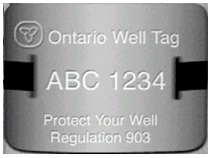
Figure 7-6: Sample Mock Up Of Well Tag
Reminder: For further information on tagging and completing well records for a well cluster, please see Chapter 13: Well Records, Documentation, Reporting & Tagging and the definitions of “well cluster” and “minor alteration” in Chapter 2: Definitions & Clarifications Table 2-1.
Footnotes
- footnote[1] Back to paragraph Nielsen, David M. 2006. Neilson Practical Handbook for Environmental Site Characterization and Groundwater Monitoring. Taylor & Francis, Boca Raton, Florida. Pages 850-851.
- footnote[2] Back to paragraph Sterrett, Robert J. 2007. Groundwater and Wells; Third Edition. Johnson Screens/a Weatherford Company. New Brighton, MN. Figure 11.3, Page 505.
- footnote[3] Back to paragraph Sterrett, Robert J. 2007. Groundwater and Wells; Third Edition. Johnson Screens/a Weatherford Company. New Brighton, MN.