9. Equipment Installation
Chapter Description
This chapter provides information, illustrations, advantages and disadvantages for the installation of pumps, caps, covers, vents and other equipment in or connected to wells. This chapter covers the requirements and exemptions for the installation of equipment in wells and provides information on the installation of equipment in wells completed above ground and in well pits.
Regulatory Requirements - Equipment Installation
Relevant Sections - The Wells Regulation
- Exemptions – Section 1.0.2
- Installation of Equipment – Sections 15.2 to 15.3
- Venting – Section 15.1
- Surface Drainage – Section 12.3
- Disinfection – Section 15
- Well Pits – Subsections 12(7) to 12(9), subsection 13(14) and Section 14.5
The Requirements - Plainly Stated - Installing Equipment
The Wells Regulation Provides Exemptions for the Following Activities Related to Equipment Installation
Exemptions for Equipment and Activities
Well licensing Requirements in the Ontario Water Resources Act and the requirements in the Wells Regulation do not apply to any of the following activities that are part of the construction of a well:
- Inspecting the well using equipment that is not left unattended in the well.
- Monitoring, sampling or testing the well using equipment that:
- is not used to test the yield of the well or the aquifer, and is not left unattended in the well; or
- is not used to test the yield of the well or the aquifer, and was previously installed in the well.
- Installing equipment for monitoring, sampling or testing a test hole or dewatering well, unless the:
- installation of the equipment involves an alteration of the well, other than notching the top of the casing; or
- equipment is used to test the yield of the well or the aquifer.
Reminder: See Chapter 3: Well Contractors & Well Technicians – Licences, Responsibilities & Exemptions for information on licensing for equipment installation activities that are not exempt from the well licensing requirements in the Ontario Water Resources Act and the requirements in the Wells Regulation.
The Wells Regulation Requires a Person Constructing a Well to Meet the Following, Unless an Exemption is Provided in This Section
Equipment in a Well
Any equipment installed in a well must be clean.
Reminder: All equipment installed in a well must not cause or have the potential to cause impairment to the water in the well or the groundwater as required under Subsection 30(1) of the Ontario Water Resources Act.
Connections to Drilled Wells
If a connection to the casing of a drilled well is made below the ground surface, a well seal or pitless adapter must be used and the connection must be made watertight.
Pitless units, which consist of a pitless adapter and casing, are also an acceptable method to connect pumping equipment to drilled wells.
A cutting torch must not be used to make an opening in the casing wall when installing a pitless adapter.
Connections to Wells Other than Drilled Wells
Any below ground connection to the casing of a well that is not a drilled well must be made watertight with durable bonding material.
Excavation beside the Casing
Any excavation created when making a below ground connection to the casing of a well must be filled with suitable sealant extending from the casing a minimum distance outward of 20cm (8 inches) and extending from the bottom of the excavation to within 20cm (8 inches) of the ground surface.
Venting- General
Unless exempt, when a new well is constructed by any method, the well must be vented to the outside atmosphere so that all gases can be safely dispersed.
Exemptions - General Venting Requirement
The above venting requirement does not apply to a:
- test hole, or
- well where the casing will be used to transmit water out of the well (e.g., a flowing well that does not have a pump).
Venting – Drilled Well with a Pump
Unless exempt, if a pump is installed in a drilled well, the following air vent requirements apply:
- An air vent must be installed with a minimum inside diameter of:
- 0.3 cm, (0.11 inch) if the inside diameter of the casing is less than 12.7 cm (5 inches), or
- 1.2 cm, (0.48 inch) if the inside diameter of the casing is 12.7 cm (5 inches) or more.
- The air vent must:
- be long enough to extend above the covering of the well pit, if a well pit exists, or
- extend above the ground surface at least 40 cm (16 inches) and at a height sufficient to prevent the entry of flood water from any anticipated flooding in the area, if no well pit exists, and
- The open end of the air vent must be shielded and screened to prevent the entry of any materials into the well.
Exemptions - Venting - Drilled Well with a Pump
The venting requirements for a drilled well installed with a pump do not apply to:
- a well with a well pit where there is no potential hazard from natural gas or any other gas, or
Venting a Well Pit
An air vent line must be installed on a new well in a new well pit and must extend above the cover of the well pit. The specific size and other requirements discussed in Venting – Drilled Well with a Pump in this Plainly Stated section do not apply.
Covering the Well
Dug or Bored
The top of the casing of a well that is constructed by digging or boring must be covered with a solid, watertight well cover, sufficient to prevent surface water and other foreign materials from entering into the well.
Drilled or Other Method
The top of the casing of a well that is constructed by any method other than digging or boring, such as drilling, must be sealed with a commercially manufactured vermin-proof well cap. This includes a properly installed and sealed sanitary well seal and a watertight and airtight well cap for a point well.
Alternative to a Well Cover
The cover or seal previously mentioned in the “Covering the Well” of the Plainly Stated section is not required if all of the following criteria are met:
- A floor has been constructed around or adjacent to the casing of the well,
- A pump is installed above or adjacent to the well,
- The top of the casing is shielded to prevent entry of any material that may impair the quality of the water in the well, and
- The casing of the well extends to at least 15 cm (6 inches) above the floor.
Reminder: The installation of a well cap or watertight well cover is considered a “minor alteration” to a well.
Disinfection
Unless exempt, as soon as possible after the construction or installation is complete, the water in the well must be dosed to a concentration of not less than 50 milligrams per litre and not more than 200 milligrams per litre of free chlorine.
Reminder: See Chapter 8: Well Disinfection for further information and Wells Regulation requirements on disinfection.
Reminder: The requirements for casing height for new wells are provided in the “Plainly Stated” section of Chapter 7: Completing the Well’s Structure and the requirements for not reducing a casing above the ground surface are provided in the “Plainly Stated” section of Chapter 11: Maintenance & Repair.
Well Pits
In most circumstances, well pits are not allowed to be constructed on new or existing wells.
In certain circumstances, however, a person constructing a well may be allowed to finish the well with a well pit. The Wells Regulation provides options for the construction of permitted well pits depending on the type of equipment used to construct the well and the well’s purpose.
The sections below in the Plainly Stated provide the Wells Regulation construction requirements for various well pit scenarios.
Permitted Well Pits for Water Supply Wells
A new well pit is permitted for a new well as long as the well is constructed with diamond drilling equipment in connection with mineral exploration.
Reminder: Diamond drilling equipment can be described as any drilling equipment that uses a diamond bit. Further clarification on the term “mineral exploration” is provided in Table 2-3 of Chapter 2: Definitions & Clarifications.
The requirements in the following sections must be met in order to install a new well pit on a well constructed with diamond drilling equipment in connection with mineral exploration.
Well Pit Walls (or Casing)
The walls of the new well pit are considered casing.
When a new well pit is constructed, the casing requirements found in Chapter 5: Constructing the Hole, Casing & Covering the Well, and Chapter 7: Completing the Well’s Structure of this manual apply to the sides of a well pit. This includes the top of the sides of the well pit (i.e., casing) being at least 40 cm (16 inches) above the highest point on the ground surface within 3 m (10 ft) radially from the outside of the well pit’s casing.
Surface drainage must not collect or pond in the vicinity of the well pit’s casing
Well Pit Floor
The floor of the new well pit must be covered with at least 10 cm (4 inches) of suitable sealant that, when set to a solid state, will be capable of supporting the weight of a person.
Cover/Seal and Vent for a Well Located in a New Well Pit
The top of the casing of the well in the new well pit must be:
- at least 40 cm (16 inches) above the floor of the well pit, and
- sealed with a commercially manufactured sanitary seal. An air vent line must be provided from the seal to above the covering of the well pit.
Well Pit Cover
The top of the new well pit must be covered with a solid, watertight cover. The well pit cover must be:
- sufficiently sealed to prevent the entry of surface water and other foreign materials which would include insects and animals, and
- fastened in place in a manner that will make it difficult for children to remove the well pit cover.
Keeping the Well Pit Dry
The new well pit must be kept dry by means of a sump pump unless the water table is substantially lower than the floor of the well pit.
If the water table is substantially lower than the floor of the well pit, the new well pit may be kept dry by means of a drainage pipe from the well pit that:
- has a one-way valve to allow water to discharge from the pit but prevents surface water and other foreign materials, including insects and animals, from entering the well pit,
- passes through the layer of sealant, and
- allows water to discharge near the perimeter of the well pit.
For additional requirements that apply to permitted well pits, see the “Creating and Filling the Annular Space for a New Well Pit” and “Surface Drainage” sections in the Plainly Stated below.
Creating and Filling the Annular Space for a New Well Pit
The person constructing the well must ensure that the entire new well pit, from the bottom of the well pit to the ground surface, is constructed with a diameter that is at least 7.6 cm (3 inches) greater than the outside diameter of the well pit’s walls (or casing).
Unless otherwise exempt, the person constructing the well must ensure that any annular space outside the new well pit’s casing is filled, from the bottom of the well pit to the ground surface, with suitable sealant.
The sealant must provide the appropriate structural strength to support the weight of persons and vehicles that may move over the area after it is filled.
If the sealant contains cement:
- it must be allowed to set according to the manufacturer’s specifications or for 12 hours, whichever is longer; and
- if after setting, the sealant has settled or subsided, it must be topped up to the ground surface.
Surface Drainage
The mounding of the ground surface beside the well must be done so that the surface drainage does not pond or collect in the vicinity of the well.
Reminder: Additional information on surface drainage can be found in Chapter 7: Completing the Well’s Structure.
Relevant Sections - Additional Regulations Or Legislation
Ontario Regulation 164/99 as amended (Electrical Safety Code) made under the Electricity Act, 1998. S.O. 1998. Chapter 15, Schedule A;
Ontario Regulation 632/05 as amended (Confined Spaces) made under the Occupational Health and Safety Act, R.S.O. 1990, Chapter 0.1;
Ontario Regulation 213/91 as amended (Construction Projects) made under the Occupational Health and Safety Act, R.S.O. 1990, Chapter 0.1;
Relevant Guidance Documents
Fleming College. 2008. Manual for Continuing Education Course Safety (for Ontario Well Technicians).
WSC PAS-97(04) – “WSC Performance Standards and Recommended Installation Procedures for Sanitary Water Well Pitless Adapters, Pitless Units, and Well Caps.” Water System Council, Washington DC. WSC website.
Well Record - Relevant Sections
Figure 9-1: Relevant Sections Of Well Record - Logistics
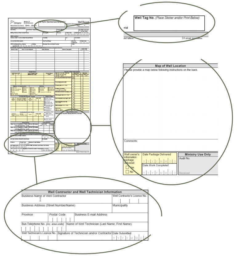
Well Tag No. - confirms that the well record is for the well being worked on.
Map of Well Location - helps find the well on the property.
Well Contractor and Well Technician Information - identifies the well contractor and provides contact information in the event that additional information is needed.
Figure 9-2: Relevant Sections Of Well Record - Construction
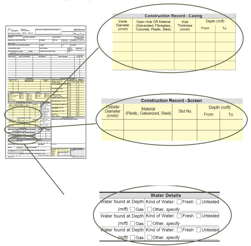
Well Casing:
- Important for clearance (i.e., well diameter) with down hole components (e.g., submersible pump)
- Identifies where casing ends or open hole starts/ends
Well Screen:
- Identifies if a well screen is present and its length, slot size and depth
- Helps ensure that the pump intake is installed above the top of the well screen
Water Details:
- Identifies location of groundwater intersected by the well
- Identifies gas that could affect pumping and cause problems or hazards in the water distribution system and well site
- Provides general remarks on the quality of water observed
Figure 9-3: Relevant Sections Of Well Record - Results Of Well Yield Testing
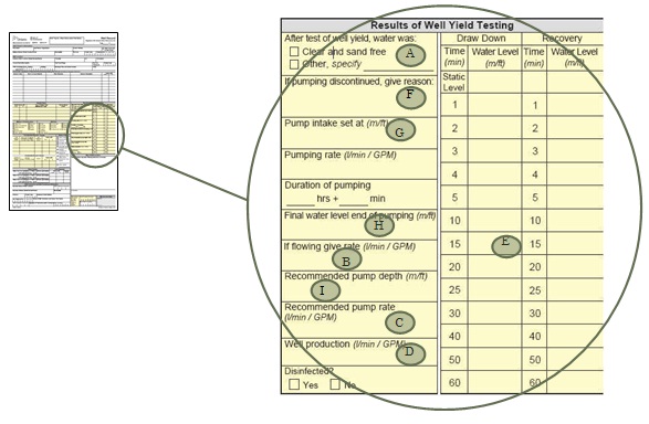
- After Test Of Well Yield:
- Indicates if there is particulate such as sand or silt in the well.
- If particulate is present then take appropriate measures to remove it from the water distribution system and install appropriate pumping equipment for these conditions.
- If Flowing Give Rate (see Chapter 12: Flowing Wells for additional details on equipment installation in flowing wells):
- If flowing conditions are encountered during construction:
- the person constructing the well must install an appropriate device to control the discharge of water.
- the person installing equipment in the well should ensure that the device installed to control the discharge remains intact or is properly re-installed after equipment installation.
- If flowing conditions are encountered during construction:
- Recommended Pumping Rate:
- Indicates recommended yield to determine appropriate pump size.
- Well Production:
- Do not use this value to size the pump as it may result in the well producing sand (e.g., well produces 29 GPM but only sand free at 7 GPM).
- Drawdown/Recovery Columns:
- Assists in the determination of the well’s efficiency, appropriate pump size and intake elevation.
- If Pumping Discontinued, Give Reasons:
- Indicates reason pumping did not last one hour. The reasons may indicate that the test may be suspect or the well may be low yielding.
- Pump Intake Set At:
- Indicates the elevation of the pump intake during the test.
- Final Water Level:
- Measured at the end of the pumping test and can be used to determine the appropriate pump size and location.
- Recommended Pump Depth:
- Values and locations are estimated by person constructing the well based on the results of the yield test.
- The installer should consider all of the information from the well yield test when determining appropriate pump size, pump rate and intake location.
Key Concepts
What To Consider When Installing Equipment
It is important to consider the protection of health, safety and the environment when installing equipment. Unless exempt, the following requirements and considerations are relevant to the installation of equipment:
- Anything that is put into the well must not impair the quality of the water,
- The purpose for installing equipment (e.g., measuring),
- The sanitary well seal, cover or cap must be properly secured on the top of the well to prevent the entry of surface water and other foreign materials,
- Other than sample collection, contaminants should not enter or exit the well during any monitoring or sampling events,
- Any space around the waterline through the side of the casing or through the top of the casing must be made watertight, and
- In the case where a pump is installed in a dewatering well, for example, the final grade of the ground surface must allow for the proper height of casing and must not allow ponding of water in the vicinity of the well.
Best Management Practice – Installing Equipment
Anyone constructing (including installing equipment in) a well should:
- install new and undamaged parts, devices and materials in the well that are certified to meet the National Sanitation Foundation (NSF) International standards,
- install parts, devices and materials that are suitable for the particular type of environment and well,
- if necessary, clean the equipment with chlorinated water as suggested by AWWA C654 standard titled “Disinfection of Wells or the Michigan’s Water Well Disinfection Manual”, and
- ensure parts are installed to the manufacturers’ specifications.
Best Management Practice – Retain Licensed Persons to Perform Exempted Activities on Wells
To help further protect groundwater, exempted activities performed wells should be done:
- by properly qualified persons (e.g., licensed well technician or qualified professional) and
- to meet the requirements found in the Wells Regulation and best management practices found in this manual that deal with well construction and abandonment.
Connections To Wells
Connections may be required for a well to function properly. Connections can be made above and below the ground surface to accommodate waterlines or instrumentation to enter a well, for instance. Any connection must be made watertight. This reduces the risk of contamination of both the well and the aquifer.
Venting The Well
The purpose of the vent is to allow the well to breathe, which allows equalizing pressures (i.e., when water is drawn out, air goes in so the column of water is at atmospheric pressure at all times) and allow the safe venting of natural and other gases to the outside atmosphere.
Well Caps And Covers
Proper covering of the well prevents the entry of foreign materials into the groundwater.
Securing the well is a safeguard against unauthorized entry into the well, vandalism or tampering. Securing the well includes ensuring that the well cap, seal or cover is on properly and may include the use of a protective cover with locking cap, barriers or fences. For information on securing the well refer to Chapter 7: Completing the Well’s Structure.
Casing Height & Mounding
The purpose of the minimum casing height is to prevent water from entering the well and to allow for venting. The purpose of mounding is to ensure that surface water runoff does not pond in the vicinity of the well and infiltrate into the well.
When installing or connecting equipment, the minimum casing height must be maintained and any mounding around the well that has been disturbed must be be restored to meet the drainage requirements found in the “Plainly Stated” section of this chapter. This does not apply if the equipment installation is exempt from the Wells Regulation (e.g., measuring the water level in a well using a water level meter) or if the equipment is installed in an exempted well (e.g., a pond).
Well Pits
A well pit is an enclosed structure, located at and below the ground surface that houses the top of the well and any associated pumping equipment. The top of the well casing extends out of the floor of the well pit.
A well pit is usually installed at or near the time of pump and associated equipment installation in the well.
The well pit can:
- protect the well from outside environmental conditions such as freezing of waterlines and the entry of surface water runoff and other foreign materials, and
- allow access to the well and pumping system from the ground surface for maintenance and repair.
Health And Safety Considerations - Trenches, Confined Spaces And Electrical
The safety manual from the well drilling continuing education course provides details regarding safety when excavating or working in trenches and confined spaces, along with precautions for working with or around electrical lines. This manual is available from Sir Sanford Fleming College (see the “Resources” section). It is recommended that these guidelines and the Occupational Health and Safety Act and its relevant regulations be reviewed prior to taking on any related tasks. Failure to be aware of the surroundings and follow appropriate safety procedures could result in serious injury or death.
Installing Pumping And Other Equipment
The Wells Regulation exempts any of the following activities that are part of the construction of a well:
- Inspecting the well using equipment that is not left unattended in the well.
- Monitoring, sampling or testing the well using equipment that:
- is not used to test the yield of the well or the aquifer, and is not left unattended in the well; or
- is not used to test the yield of the well or the aquifer, and was previously installed in the well.
- Installing equipment for monitoring, sampling or testing a test hole or dewatering well, unless:
- the installation of the equipment involves an alteration of the well, other than notching the top of the casing; or
- the equipment is used to test the yield of the well or the aquifer.
Any equipment installed in a well must be clean as required by the Wells Regulation.
Reminder: All equipment installed in a well must not cause or have the potential to cause impairment to the water in the well or the groundwater as required under subsection 30(1) of the Ontario Water Resources Act.
Reminder: For further information on what activities are exempt and what activities and wells require licensing, see Chapter 3: Well Contractors & Well Technicians – Licences, Responsibilities & Exemptions.
Best Management Practice – Installing Equipment
Anyone constructing a new well or working on an existing well should:
- install new parts, devices and materials in drinking water wells that are certified to meet the National Sanitation Foundation (NSF) International Standard 61 Drinking Water System Components – Health Effects
footnote 1 . Verify the components are certified by searching on the NSF 61 Products and Services Database and by looking for the NSF logo on the equipment. - install parts, devices and materials that are suitable for the particular type of environment and well.
- clean the equipment with chlorinated water as suggested by AWWA C654 Disinfection of Wells standard or the Michigan’s Water Well Disinfection Manual if necessary.
- ensure parts are installed to the manufacturer’s specifications.
Best Management Practice – Have Well Record on Hand
The person installing the pump should have the well record and the information on Figure 9-1 to Figure 9-3 available any time pump work or other equipment installation is carried out on a well.
Pump Terms & Facts
A water well pump is designed to move water by a physical or mechanical action.
- Pump
- includes associated pumping equipment.
Horsepower of the pump, outlet pressure in metres (or feet) of head, rate of water flow and inlet suction in metres (or feet) of head are key factors in selecting a pump. The head is considered the height the pump can raise a column of water at atmospheric pressure. Pressure is the amount of force acting on a unit area. Two units that may be used to describe pressure are psi (pounds force per square inch), and kPa (Kilopascals).
To select the type of pump, a system curve graph is created describing the relationship between the system’s head and flow rate. Also a pump performance curve graph is created describing the relationship between the head versus the flow rate of the pump. By combining the two graphs, the pump type, horsepower and best operating system can be selected. Further information on pump selection may be found in Groundwater and Wells, Third Edition, 2007
Table 9-1 provides common acronyms for flow rate and head parameters used in the installation of pumps and associated equipment. Table 9-2 provides pressure to head conversions used in pump selection.
| Acronym | Term |
|---|---|
| m of head | Metres of head above pump intake |
| ft of head | Feet of Head above pump intake |
| TDH | Total Dynamic Head = Service pressure + pumping level + elevation + friction loss |
| LPH | Litres per Hour |
| LPM | Litres per Minute |
| GPH | Gallons per Hour |
| GPM | Gallons per Minute |
| Head Parameters | PSI (pounds per square inch) |
kPa (kilopascals) |
|---|---|---|
| Conversion between units | 1PSI = 6.9kPa | 1kPa = 0.145PSI |
| Pressure of a column of water | = head in meters × 1.422 (1m of head = 1.422 PSI) |
= head in meters × 9.807 (1m of head = 9.807 kPa) |
| Pressure of a column of water | = head in feet × 0.432 (1ft of head = 0.432 PSI) |
= head in feet × 2.989 (1ft of head = 2.989 kPa) |
| Metres of head of a column of water per unit of pressure | = pressure (PSI) × 0.703 (1 PSI = 0.703 m of head) |
= pressure (kPa) × 0.102 (1kPa = 0.102 m of head) |
| Feet of head of a column of water per unit of pressure | = pressure (PSI) × 2.31 (1 PSI = 2.31ftof head) |
= pressure (kPa) × 0.335 (“ahead of” 1kPa = 0.335ft of head) |
| Distance column of water raised per unit of pressure | 1 PSI will raise a column of water 0.703 m (2.31 ft); regardless of the column’s diameter. | 1kPa will raise a column of water 0.1 m (0.335ft); regardless of the column’s diameter. |
| Atmospheric Pressure and Head at sea level | 14.7PSI (14.7 PSI × 0.703 = 10.34 m of head) (14.7 PSI × 2.31 = 33.95 ft of head) |
101.35kPa (101.35kPa × 0.102 = 10.34 m of head) (101.35kPa × 0.335 = 33.95 ft of head) |
The volume and weight of water are other considerations when selecting a pump. The following are a few common facts related to the volume and weight of water when installing a pump in a well:
- An Imperial gallon of fresh water weighs 4.5 kg (10 lbs).
- One litre of fresh water weighs 1 kg (2.2lbs).
- A cubic foot of water contains 0.028 cubic metres, 7.48 US gallons, or 6.24 Imperial gallons; and weighs 28.3 kg (62.4 lbs).
- A cubic metre of water contains 265 US gallons or 220 Imperial gallons.
- Volume of water per metre (or foot) in some wells:
- 10.8 cm (4.25 inches) inside diameter contains 9.2 litres per metre (0.61 gallons per foot)
- 13.3 cm (5.25 inches) inside diameter contains 13.9 litres per metre (0.94 gallons per foot)
- 15.9 cm (6.25 inches) inside diameter contains 19.9 litres per metre (1.33 gallons per foot)
- 0.91 m (3ft) diameter bored or dug well contains 656.1 litres per metre (44.0 gallons per foot)
Pump Types
The major pump types that are typically installed in wells are:
- Centrifugal pumps
- Jet pumps – shallow and deep
- Submersible pumps
- Variable speed constant pressure pumps
- Deep well turbine pumps
- Vertical turbine pumps
Table 9-3 provides details for the advantages, disadvantages, general capabilities and applicable well types for these pumps.
| Pump Type | Advantages | Disadvantages | Average Pumping Level Capability | Applicable Well Type(s) |
|---|---|---|---|---|
| Centrifugal Pump |
|
|
|
|
| Jet Pump |
|
|
|
|
| Submersible Pumps |
|
|
|
|
| Variable Speed Constant Pressure Pumps (Can be submersible or jet pumps) |
|
|
|
|
| Vertical Turbine Pump |
|
|
|
|
Graphics Of Installed Pumps
The following graphics illustrate the installation layout for the following scenarios:
- Drilled Well with Shallow Jet Pump (Figure 9-4)
- Drilled Well with Deep Jet Pump (Figure 9-5)
- Drilled Well with Submersible Pump (Figure 9-6)
- Dug and Bored Wells with Shallow Jet Pump (Figure 9-7)
- Dug and Bored Wells with Submersible Pump (Figure 9-8)
- Driven Point Well with Shallow Well Pump (Figure 9-9)
The graphics show examples of installation only. They are not to scale. All dimensions and locations are for illustrative purposes only. Each of the wells shown Figure 9-4 through Figure 9-9 may encounter conditions that may require specialized design or construction. For example:
- flowing artesian conditions,
- presence of gas, or
- breathing (sucking & blowing) conditions where the well and aquifer formation are significantly affected by changes in atmospheric pressure
Reminder: The illustrations and graphics do not depict every circumstance and do not necessarily represent full compliance with other requirements found in the Wells Regulation.
Reminder: See the tables in the Tools Section at the end of this chapter for Drop Pipe and Down Hole Component information.
Reminder: All figures and diagrams are for illustrative purposes only and do not necessarily represent full compliance with other requirements found in the Wells Regulation.
Figure 9-4: Drilled Well With Shallow Jet Pump
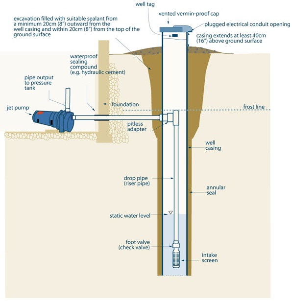
Figure 9-4 is a cross-section diagram of a drilled well with a shallow jet pump. A casing extends from at least 40 centimetres (16 inches) above the ground surface into the hole. A vermin-proof well cap is located on top of the well. The electrical conduit opening, located on the bottom right of the vermin-proof cap, has been plugged. A well tag has been permanently affixed to the casing above the ground surface. The ground surface around the well has been mounded to prevent ponding of water in the vicinity of the well.
A cross-section of a building’s basement is shown to the left of the drilled well. To the left of the well is a vertical wall and basement floor of the foundation. The vertical wall extends from above the ground surface to just below the frost line. At the bottom of the vertical wall, a horizontal floor extends from the bottom of the vertical wall to the left. In the subsurface and above the horizontal floor, a horizontal blue dotted line represents the frost line. The frost line extends from the vertical wall to the right side of the diagram.
A jet pump is shown in the diagram lying on top of the basement’s floor and to the left of the vertical wall. A vertical output pipe extends vertically from the jet pump. A horizontal water pipe extends horizontally from the jet pump to the right through the vertical wall and through the side of the casing into the well. The horizontal pipe is sealed to the vertical wall with a waterproof sealing compound (e.g., hydraulic cement). The horizontal pipe is sealed to the casing with a pitless adapter. The horizontal pipe is located below the frost line.
A drop pipe (or riser pipe) is attached to the interior of the pitless adapter inside the well. The drop pipe extends below the static water level to a foot valve (or check valve). An intake screen is attached to the bottom of the foot valve.
An excavation is located around the casing. The excavation extends from the ground surface to just below the pitless adapter. The excavation is filled with suitable sealant. The suitable sealant extends a minimum 20 centimetres (8 inches) outward from the well casing and within minimum 20 centimetres (8 inches) from the top of the ground surface. Below the excavation, there is an annular seal between the outside of the casing and the side of the hole.
Reminder: This figure is not to scale, it is for illustrative purposes, and does not necessarily represent full compliance with other requirements found in the Wells Regulation. It does not depict every circumstance
.
Figure 9-5: Drilled Well With Deep Jet Pump
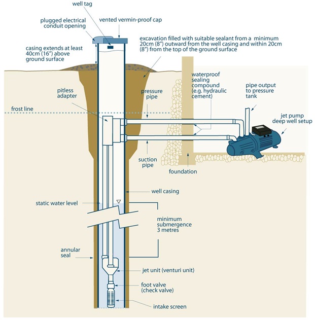
Figure 9-5 is a cross-section diagram of a drilled well with a deep jet pump. A casing extends from at least 40 centimetres (16 inches) above the ground surface into the hole. A vermin-proof well cap is located on top of the well. The electrical conduit opening, located on the bottom left of the vermin-proof cap has been plugged. A well tag has been permanently affixed to the casing above the ground surface. The ground surface around the well has been mounded to prevent ponding of water in the vicinity of the well.
A cross-section of a building’s basement is shown to the right of the drilled well. To the right of the well is a vertical wall of the basement’s foundation. The vertical wall extends from above the ground surface to just below the frost line. At the bottom of the vertical wall, a horizontal floor extends from the bottom of the vertical wall to the right. In the subsurface and above the horizontal floor, a horizontal blue dotted line represents the frost line. The frost line extends from the vertical wall to the left side of the diagram.
A deep well setup jet pump is shown in the diagram lying on top of the basement’s floor and to the right of the vertical wall. A vertical output pipe extends vertically from the jet pump. A horizontal pressure pipe extends horizontally from the jet pump to the left through the vertical wall and through the side of the casing into the well. The horizontal pressure pipe is sealed to the vertical wall with a waterproof sealing compound (e.g., hydraulic cement). The horizontal pressure pipe is sealed to the casing with a pitless adapter. The horizontal pressure pipe is located below the frost line. A horizontal suction pipe extends horizontally from the jet pump to the left through the vertical wall and through the side of the casing into the well. The horizontal suction pipe is sealed to the vertical wall with a waterproof sealing compound (e.g., hydraulic cement). The horizontal suction pipe is sealed to the casing with a pitless adapter. The horizontal suction pipe is located below the frost line.
A drop pressure pipe and suction pipe are attached to the interior of the pitless adapter inside the well. The drop pipes extend a minimum 3 metres below the static water level. A jet unit (venturi unit) is attached to the bottom of the two drop pipes. A foot valve (check valve is attached to the bottom of the jet unit (venturi unit). An intake screen is attached to the bottom of the foot valve.
An excavation is located around the casing. The excavation extends from the ground surface to just below the pitless adapter. The excavation is filled with suitable sealant. The suitable sealant extends a minimum 20 centimetres (8 inches) outward from the well casing and within minimum 20 centimetres (8 inches) from the top of the ground surface. Below the excavation, there is an annular seal between the outside of the casing and the side of the hole.
Reminder: This figure is not to scale, it is for illustrative purposes, and does not necessarily represent full compliance with other requirements found in the Wells Regulation. It does not depict every circumstance.
Figure 9-6: Drilled Well With Submersible Pump
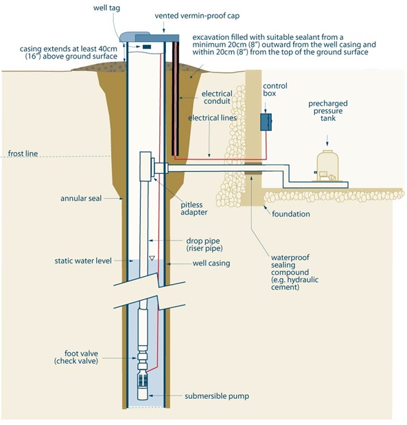
Figure 9-6 is a cross-section diagram of a drilled well with a submersible pump. A casing extends from at least 40 centimetres (16 inches) above the ground surface into the hole. A vermin-proof well cap is located on top of the well. A well tag has been permanently affixed to the casing above the ground surface. The ground surface around the well has been mounded to prevent ponding of water in the vicinity of the well.
An excavation is located around the casing. The excavation extends from the ground surface to just below the pitless adapter. The excavation is filled with suitable sealant. The suitable sealant extends a minimum 20 centimetres (8 inches) outward from the well casing and within minimum 20 centimetres (8 inches) from the top of the ground surface. Below the excavation, there is an annular seal between the outside of the casing and the side of the hole.
A cross-section of a building’s basement is shown to the right of the drilled well. To the right of the well is a vertical wall of the foundation. The vertical wall extends from above the ground surface to just below the frost line. At the bottom of the vertical wall, a horizontal floor extends from the bottom of the vertical wall to the right. In the subsurface and above the horizontal floor, a horizontal blue dotted line represents the frost line. The frost line extends from the vertical wall to the left side of the diagram.
A precharged pressure tank is shown in the diagram lying on top of the basement’s floor and to the right of the vertical wall. A horizontal pressure pipe extends horizontally from the pressure tank to the left through the vertical wall and through the side of the casing into the well. The horizontal pressure pipe is sealed to the vertical wall with a waterproof sealing compound (e.g., hydraulic cement). The horizontal pressure pipe is sealed to the casing with a pitless adapter. The horizontal pressure pipe is located below the frost line.
A drop pipe is attached to the interior of the pitless adapter inside the well. The drop pipe extends below the static water level to a foot valve (or check valve). A submersible pump is attached to the bottom of the foot valve.
An electrical control box is attached to the interior of the vertical wall. An electrical cable extends vertically below the electrical control box. The electrical cable turns to the right and extends to the left through the vertical wall into the lower portion of the excavation around the well. The electrical cable turns upward into an electrical conduit. The electrical cable and conduit extend upward into the bottom of the vermin-proof well cap. The electrical cable extends through the well cap and turns downward into the well. The electrical cable extends downward in the well and attaches to the submersible pump.
Reminder: This figure is not to scale, it is for illustrative purposes, and does not necessarily represent full compliance with other requirements found in the Wells Regulation. It does not depict every circumstance.
Figure 9-7: Dug And Bored Wells With Concrete Casing And A Shallow Lift Pump
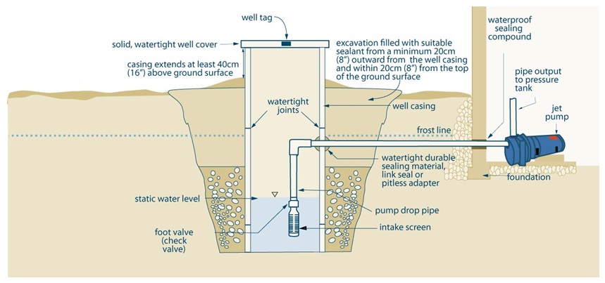
Figure 9-7 is a cross-section diagram of a dug or bored wells with concrete casing and a shallow lift pump. A casing extends from at least 40 centimetres (16 inches) above the ground surface into the hole. There are watertight joints between sections of casing. A solid, watertight well cover is located on top of the well. A well tag has been permanently affixed to the casing above the ground surface. The ground surface around the well has been mounded to prevent ponding of water in the vicinity of the well.
An excavation is located around the casing. The excavation extends from the ground surface to just below the pitless adapter. The excavation is filled with suitable sealant. The suitable sealant extends a minimum 20 centimetres (8 inches) outward from the well casing and within minimum 20 centimetres (8 inches) from the top of the ground surface. Below the excavation, there is an annular seal between the outside of the casing and the side of the hole.
A cross-section of a building’s basement is shown to the right of the dug (or bored) well. To the right of the well is a vertical wall of the basement. The vertical wall extends from above the ground surface to just below the frost line. At the bottom of the vertical wall, a horizontal floor extends from the bottom of the vertical wall to the right. In the subsurface and above the horizontal floor, a horizontal blue dotted line represents the frost line. The frost line extends from the vertical wall to the left side of the diagram.
A jet pump is shown in the diagram lying on top of the basement’s floor and to the right of the vertical wall. A vertical output pipe extends vertically from the jet pump. A horizontal pressure pipe extends horizontally from the jet pump to the left through the vertical wall and through the side of the casing into the well. The horizontal pipe is sealed to the vertical wall with a waterproof sealing compound (e.g., hydraulic cement). The horizontal pipe is sealed to the casing with a durable sealing material, link seal or pitless adapter. The horizontal pipe is located below the frost line.
A drop pipe (or riser pipe) is attached to the interior of the pitless adapter or horizontal pipe inside the well. The drop pipe extends below the static water level to a foot valve (or check valve). An intake screen is attached to the bottom of the foot valve.
Reminder: This figure is not to scale, it is for illustrative purposes, and does not necessarily represent full compliance with other requirements found in the Wells Regulation. It does not depict every circumstance.
Reminder: Larger diameter wells must not be entered as they are dangerous unless adequate safety precautions are taken using Confined Spaces Regulation 632/05 under the Occupational Health and Safety Act.
Figure 9-8: Dug And Bored Wells With Concrete Casing And A Submersible Pump
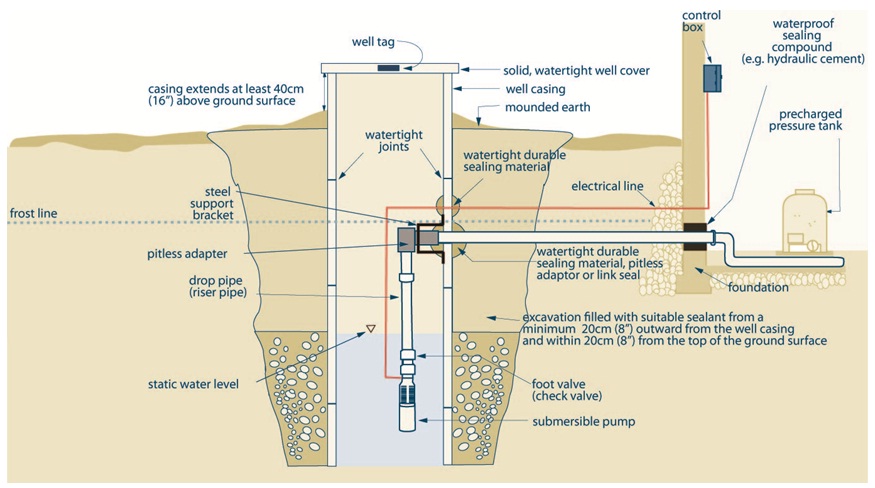
Figure 9-8 is a cross-section diagram of a dug or bored wells with concrete casing and a submersible pump. A casing extends from at least 40 centimetres (16 inches) above the ground surface into the hole. The ground surface around the well casing has been mounded. There are watertight joints between sections of casing. A solid, watertight well cover is located on top of the well. A well tag has been permanently affixed to the casing above the ground surface. The ground surface around the well has been mounded to prevent ponding of water in the vicinity of the well.
An excavation is located around the casing. The excavation extends from the ground surface to just below the pitless adapter. The excavation is filled with suitable sealant. The suitable sealant extends a minimum 20 centimetres (8 inches) outward from the well casing and within minimum 20 centimetres (8 inches) from the top of the ground surface. Below the excavation, there is an annular seal between the outside of the casing and the side of the hole.
A cross-section of a building’s basement is shown to the right of the dug (or bored) well. To the right of the well is a vertical wall of the basement. The vertical wall extends from above the ground surface to just below the frost line. At the bottom of the vertical wall, a horizontal floor extends from the bottom of the vertical wall to the right. In the subsurface and above the horizontal floor, a horizontal blue dotted line represents the frost line. The frost line extends from the vertical wall to the left side of the diagram.
A precharged pressure tank is shown in the diagram lying on top of the basement’s floor and to the right of the vertical wall. A horizontal pressure pipe extends horizontally from the pressure tank to the left through the vertical wall and through the side of the casing into the well. The horizontal pressure pipe is sealed to the vertical wall with a waterproof sealing compound (e.g., hydraulic cement). The horizontal pipe is sealed to the casing with a durable sealing material, link seal or pitless adapter. The horizontal pressure pipe is located below the frost line.
A drop pipe is attached to the interior of the pitless adapter inside the well. The drop pipe extends below the static water level to a foot valve (or check valve). A submersible pump is attached to the bottom of the foot valve.
An electrical control box is attached to the interior of the vertical wall of the basement. An electrical cable extends vertically below the electrical control box. The electrical cable turns to the right and extends to the left through the vertical wall into the lower portion of the excavation around and the casing of the well. The electrical cable is sealed to the vertical wall with a waterproof sealing compound. The electrical cable extends downward in the well and attaches to the submersible pump.
Reminder: This figure is not to scale, it is for illustrative purposes, and does not necessarily represent full compliance with other requirements found in the Wells Regulation. It does not depict every circumstance.
Reminder: Larger Diameter wells must not be entered as they are dangerous unless adequate safety precautions are taken using Confined Spaces Regulation 632/05 under the Occupational Health and Safety Act.
Reminder: The connection for the horizontal and vertical pipes shown would be supported by using a pitless adapter and supporting steel bracket anchored to the inside of the casing.
Figure 9-9: Driven Point Well With Shallow Lift Pump
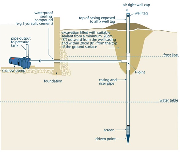
Figure 9-9 is a cross-section diagram of a driven point well with a shallow lift pump. A casing extends from at least 40 centimetres (16 inches) above the ground surface into the hole. An air tight well cap is located on top of the well. The electrical conduit opening, located on the bottom right of the air tight well cap has been plugged. A well tag has been permanently affixed to the casing above the ground surface.
An excavation is located around the casing. The excavation extends from the ground surface to just below the pitless adapter. The excavation is filled with suitable sealant. The suitable sealant extends a minimum 20 centimetres (8 inches) outward from the well casing and within minimum 20 centimetres (8 inches) from the top of the ground surface. Below the excavation, there is an annular seal between the outside of the casing and the side of the hole.
A cross-section of a building’s basement is shown to the left of the driven point well. To the left of the well is a vertical wall of the foundation. The vertical wall extends from above the ground surface to just below the frost line. At the bottom of the vertical wall, a horizontal floor extends from the bottom of the vertical wall to the left. In the subsurface and above the horizontal floor, a horizontal blue dotted line represents the frost line. The frost line extends from the vertical wall to the right side of the diagram.
A shallow pump is shown in the diagram lying on top of the basement’s floor and to the left of the vertical wall. A vertical output pipe extends vertically from the shallow pump. A horizontal water pipe extends horizontally from the shallow pump to the right through the vertical wall and through the side of the casing into the well. The horizontal pipe is sealed to the vertical wall with a waterproof sealing compound (e.g., hydraulic cement). The horizontal pipe is sealed to the casing at a “T” joint connection. The horizontal pipe is located below the frost line.
Reminder: Conditions and considerations for using a shallow well lift pump in a driven point well are as follows:
- Because of the small diameter of the well, this is generally the only type of pump that is suitable but a jet pump may also work.
- For new point wells constructed after December 31, 2007, a T-connection is made below the ground surface with the waterline (lateral pipe) attaching to the well casing.
- The new point well also will have an air tight well cap.
- The entire assembly must be airtight in order for the pump to maintain a vacuum in the entire well and waterline.
- The T-configuration allows access to the well and, if necessary, allows access to conduct maintenance on the well such as shock chlorination.
- The design of the point well should be able to withstand freezing and thawing.
Reminder: This figure is not to scale, it is for illustrative purposes, and does not necessarily represent full compliance with other requirements found in the Wells Regulation. It does not depict every circumstance.
Reminder: This set up is similar for jetted wells attached to a shallow well pump.
Below Ground Connections To Wells
Drilled Wells
The Wells Regulation - When making below ground connections to the casing of a drilled well, the person constructing the well must use a well seal or pitless adapter (including pitless units) and the connection must be watertight.
Pitless units or pitless adapters allow lateral pipes (i.e., waterlines) outside a drilled well casing to connect to drop pipes (waterlines) inside the well.
Reminder: A drop pipe usually extends from the connection at the pitless adapter to the pump or intake portion of the pumping equipment inside the well.
Pitless Adapters
A drop pipe usually extends from the connection at the pitless adapter to the pump or intake portion of the pumping equipment inside the well.
- connects downhole pumping equipment to piping in the trench, and
- allows the downhole pumping equipment to be easily removed while standing at the ground surface.
The size and number of holes through the casing depends on the design of the pitless adapter and pump equipment.
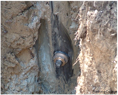
To ensure that the connection is watertight, it is necessary that person installing the pitless adapter follow the manufacturer’s specifications and ensure that the adapter being installed is appropriate for the environment and the well design (e.g., casing size).
The Wells Regulation - The person constructing the well must not use a cutting torch to make an opening in the casing wall to accommodate a pitless adapter.
A cutting torch creates an opening that is too irregular to be made watertight.
Best Management Practice – Preparing to Install Pitless Adapter
Before installing the pitless adapter, the person installing equipment in the well should cut the hole in the casing wall with a hole saw and should remove metal burs along the open hole’s edges to ensure that the pitless adapter creates a watertight fit to the casing.
A cordless drill helps eliminate the possibility of electrocution.
Figure 9-10: Pitless Adapter
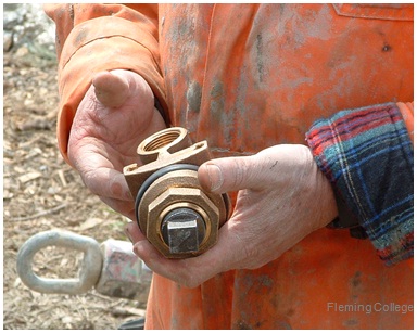
Figure 9-11: Pitless Adapter Installed
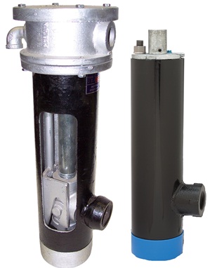
Pitless Units
A pitless unit is a commercially manufactured piece of well casing with a pitless adapter already installed through the wall of the unit. It is primarily designed to make a watertight connection on top of the well casing.
Typically, a person installing a pitless unit will cut the top of well casing below the frost level. The pitless unit is then installed onto the top of the well casing by either welding or using a special clamp device.
To ensure that the connection is watertight to the well, it is important that persons installing pitless units follow manufacturer’s specifications and ensure that the unit being installed is appropriate for the environment and the well design (e.g., casing size).
Figure 9-12: Cross-Section Of Pitless Unit
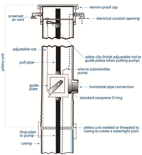
Figure 9-12 is a cross-section diagram of a pitless unit. The pitless unit is shown as a vertical pipe. A vermin-proof well cap is affixed to the top of the pitless unit. Below the vermin-proof cap and on the left side of the pitless unit, an air vent extends out of the pitless unit. Below the cap and on the right side of the pitless unit, an electrical conduit opening has been affixed to the exterior of the pitless unit to allow an electrical cable to enter into the well. The bottom of the pitless unit is attached to a casing using a watertight welded or threaded joint.
In the interior of the pitless unit, there is a vertical pull pipe that extends from the top of the pitless unit to a guide plate. To the left of the pull pipe an adjustable rod extends from the top of the pitless unit to the guide plate. A safety clip is attached to the top of the guide plate and pull pipe. The safety clip holds adjustable rod to guide plates when pulling the pump. A horizontal connection extends through the right side of the pitless unit from the guide plate. A standard neoprene O-ring seals the interior of the pitless unit around the horizontal connection. A drop pipe extends below the guide plate to the pump.
An electrical cable extends through the electrical conduit opening and into the pitless unit. The electrical cable extends downward through the pitless unit and well to the submersible pump.
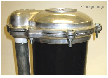
Figure 9-13: Photographs Of Pitless Units
Best Management Practice – Installation of Pitless Adapters and Pitless Units
The person installing the equipment in the well should review and follow the standards and recommendations found in the Water Systems Council brochure titled WSC Performance Standards and Recommended Installation Procedures for Sanitary Water Well Pitless Adapters, Pitless Units, and Well Caps
The brochure is available at theWater System Council website.
Best Management Practice – Connecting Waterlines above the Ground Surface in a Drilled Well
If the person cuts a hole in a drilled well casing above the ground surface, the person should ensure that, at all times, the connection to the casing is watertight.
Sanitary Wells Seals
Sanitary well seals are primarily designed to create a watertight seal where the waterlines, air vents and electrical lines extend through the top of the well casing.
A sanitary well seal consists of a neoprene gasket between two steel plates. When the two plates are tightened together, the neoprene gasket expands, which seals waterlines, air vents, electrical lines and the casing.
When installing a sanitary well seal, it is necessary to follow the manufacturer’s specifications to ensure that the connection is watertight and the appropriate seal is installed for the environment and the well design.
Figure 9-14: Sanitary Well Seal
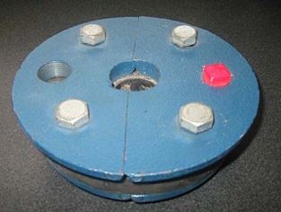
The photograph shows an example of one kind of sanitary well seal. In this case, a blue steel plate is underlain by a black neoprene gasket. The gasket is underlain by another blue steel plate. One waterline can pass through the centre of the well seal. An air vent can be threaded onto the seal on the left side of the well seal. The red plug can be removed on the right side of the well seal to allow for an electrical line or other equipment through the well seal. By tightening the four steel bolts on top of the well seal, the two plates are tightened together expanding the neoprene gasket. The squeezed gasket seals the waterline, electrical line and the casing. The well seal is typically found at the top of the well casing. Other sanitary well seals have two holes for two waterline installations used in jet pumps.
Other Wells (e.g.,Dug And Bored Wells)
The Wells Regulation - When making a below ground connection to a well casing of a well other than a drilled well (e.g., constructed by boring, digging or augering equipment), the person constructing the well must make the connection watertight with a durable bonding material.
Any bonding material must be durable and adhere to the side of the casing and the waterline. Also, the bonding material must not impair the water quality.
Large diameter corrugated conduits or other pipe used to protect waterlines in trenches should not extend through the well casing. Only properly connected and sealed waterlines and electrical lines should extend through the casing.
It is important to know and follow the manufacturers’ specifications for bonding material and installation of waterlines through the well casing (e.g., fiberglass, galvanized and concrete).
Best Management Practice – Waterline Connection through Concrete Casing
A concrete tile pitless adapter should be installed when a connection to a waterline is made through the side of a concrete casing.
As an alternative, a steel supporting bracket can be used on the inside of the well casing. The bracket will attach to the pitless adapter and allow the lateral pipe to extend through the casing and into the well. The horizontal pipe connection to the casing must be sealed with hydraulic cement or other durable bonding material that will not impair the water quality.
Reminder: Hydraulic cement looks like other cement and is used to stop water leaks through cracks and faults in concrete. Tape should be used to hold the cement in the connection area while it sets (cures).
Best Management Practice – Connecting Waterlines above the Ground Surface in a Well that is Not a Drilled Well
If the person cuts a hole into a casing above the ground surface of a well that is not a drilled well, the person should ensure that, at all times, the connection to the casing is watertight.
Installing Suitable Sealant Into Trench
To install a waterline and electrical wire from the well to the building’s plumbing and electrical box, a trench is typically excavated from the well to the building. The trench will expose the side of the well. The depth of the trench is typically below the frost line to minimize the risk that the horizontal waterline from the well to the building’s plumbing will freeze.
The Wells Regulation - When making a below ground connection to the casing of a well, the person constructing the well must fill any outside excavation with suitable sealant extending from the casing a minimum distance outward of 20cm (8 inches) and extending from the bottom of the excavation to within 20cm (8 inches) of the ground surface.
The person excavating the trench should consider the direction of the trench and the proximity to potential sources of contamination as the trench can act as a preferential pathway for contaminants.
Best Management Practice – Sealing the Excavation
It is important to consider the direction of the trench and the proximity to potential sources of contamination as the trench can act as a pathway for contaminants to migrate to the well site or building.
If suitable sealant has been installed to a horizontal distance that is greater than 20cm (8 inches) from the well casing (during the filling of the well’s annular space), then the trench should be backfilled with suitable sealant from the outside of the well casing to at least the same distance as the original sealant.
When backfilling the remainder of the trench, the person installing the equipment should:
- place fully hydrated bentonite berms at set intervals at the bottom of the trench and over the top of the waterlines and electrical wires to help minimize horizontal movement of water and contaminants along the trench, and
- backfill the trench with clean soil that can withstand the weight of persons, animals and vehicles and will not promote the movement of water
If a larger diameter pipe is used to house the waterline and electrical wires from the well to a structure, the person installing the equipment should:
- stop the larger diameter pipe before the outside of the building and before the trench’s sealant at the well to prevent surface water and foreign materials from entering the well site or building,
- ensure the larger diameter pipe is not perforated and is strong enough to withstand corrosion and the weight of the overlying materials, and
- take adequate precautions to prevent water or foreign material from entering the larger diameter pipe and from being directed toward any building, foundation or the well.
Venting The Well
The purpose of the air vent is to allow the well to breathe, which allows equalizing pressures (i.e., when water is drawn out, air goes in so the column of water remains at atmospheric pressure at all times) and the venting of natural gases.
Venting After New Well Construction
The Wells Regulation - When constructing a new well, the well must be vented to the outside atmosphere in a manner that will safely disperse all gases. This requirement does not apply to a:
- test hole, or
- well where the casing will be used to transmit water out of the well (e.g., driven point well).
Reminder: Flowing wells are not exempt from the regulatory requirement for venting unless the casing is used in some form to transmit water out of the well or the well is a test hole. A mechanical or inflatable packer with an air release valve and air vacuum relief valve may be installed to vent the well to allow air into and out of the well during pumping. See Chapter 12: Flowing Wells for further information.
Venting During Pump Installation In Drilled Wells
The Wells Regulation - Unless exempt, if a pump is installed in a drilled well, the person constructing the well must install an air vent on the well and meet the following requirements:
- An air vent must have a minimum inside diameter of:
- 0.3 cm (0.12 inch) for a well casing that has an inside diameter < 12.7 cm (5 inches), or
- 1.2 cm (0.47 inch) for a well casing that has an inside diameter ≥ 12.7 cm (5 inches)
- In an area where there is potential for flooding, the air vent on a well must extend above the maximum anticipated flooding level and not less than 40 cm (16 inches) above the ground surface.
- On a drilled well in a well pit, the air vent may have a sufficient length to extend above the covering of the well pit.
- The open end of the air vent must be shielded and screened to prevent the entry of foreign materials (e.g., insects) into the well.
Reminder: A vent with a larger inside diameter will reduce the risk of the vent freezing during periods of extreme cold temperatures.
Best Management Practice – Venting Wells
Any well, even a well in a well pit, should be vented to disperse gases. A well in a well pit should be vented with a shielded and screened vent (see Figure 9-29 in this chapter).
Reminder: The largest possible vent area (cross-sectional area) should be selected to help prevent freezing during periods of extreme cold.
Figure 9-15: Watertight Cap With Extendable Screened Air Vent Located Above The Well Cap
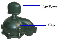
Figure 9-16: Watertight Cap With Snorkel Vent Used To Prevent Flood Water From Entering The Top Of A Drilled Well
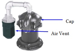
Figure 9-17: PVC Well Seal Air Vent
This shows an example of a ½ inch air vent that can be threaded on a sanitary well seal as the one shown in Figure 9-14.
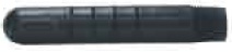
Figure 9-18: Vented Vermin Proof Cap Attached To Well Casing
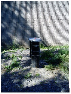
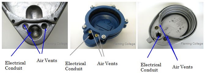
Figure 9-19: Vent Locations On The Underneath Portion Of Three Vermin Proof Caps Commonly Used In Ontario
Wells Encountering Gas
The Wells Regulation - Where a well is constructed and natural gas is encountered, the person constructing the well must immediately notify the well purchaser, the owner of the land on which the well is situated and the Director that the condition exists.
The Wells Regulation - If a well is producing a natural gas or other gas and the gas is detected, the well owner must do at least one of the following:
- Abandon the well and take the necessary steps to plug and seal the well,
- Take the necessary measures to manage the gas in a way that prevents any potential hazards and ensure the measures are functional at all times, or
- Seek the written consent from the Director to allow for the continued use of the well (see Chapter 14: Abandonment: When to Plug & Seal Wells).
Reminder: See the Encountering Gas, Contamination and Water Quality Problems section of Chapter 5: Constructing the Hole, Casing & Covering the Well for further information and best management practices dealing with natural gas.
Best Management Practice – Venting Natural Gas
If natural gas or other gas has been identified, then the person constructing the well should consider retaining the services of a Professional Engineer or Professional Geoscientist experienced in groundwater and water wells producing gas. The Professional Engineer or Professional Geoscientist should:
- assess the well and the hydrogeology and geology around the well,
- provide the well owner with written recommendations, and
- confirm that the recommendations have been implemented and the gas concerns have been abated at the site.
Best Management Practice – Notification for Gases Other than Natural Gas
When “other” gases (e.g., benzene gas from a petroleum hydrocarbon spill) that cause, or may cause, adverse effects on public health and/or the natural environment are encountered, then the person constructing the well should notify the Spills Action Centre at
Wells Caps And Covers
The purpose of well caps and covers is to prevent the entry of surface water and other foreign material into the well. The following requirements will apply to covering the well unless an exempted activity is being performed.
The Wells Regulation - If the well is constructed by a method other than boring and digging (i.e., jetting, drilling, and driving) the person constructing the well must seal the top of the casing with a commercially manufactured vermin-proof well cap.
For example, wells constructed by drilling, jetting and driving are captured by this well cap requirement.
The Wells Regulation - If a well is constructed by boring and digging, the person constructing the well must cover the top of the casing with a solid, watertight well cover that prevents the entry of surface water and other foreign materials.
Preventing the entry of other materials includes designing the well cover to be of sufficient strength to withstand any known weight that might be applied to the well cover or cap and the freezing and thawing action that may cause the cover to break.
Reminder: It is important that anyone constructing a well install the well cover or cap to the design specifications provided by the manufacturer and ensure that the design will work for the environment and well.
Covering The Well
Dug Or Bored
The person constructing the well must cover the top of the well casing with a solid watertight well cover so that surface water and other foreign materials can not enter into the well. This includes fastening and securing the cover to reduce the risk of children being able to access the well.
Figure 9-20: Dug Well With A Solid Well Cover
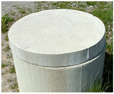
Figure 9-21: Dug Well Cover With Watertight Plastic Access Lid Added To Well Cover
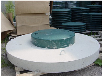
Figure 9-21 shows the green coloured access lid is sealed to the top of the concrete cover using a butyl joint non toxic sealing material (mastic sealing material). An opening (not shown) exists in the centre of the concrete. The top of the access lid is affixed to the access lid riser using screws. The access lid and remaining well cover must prevent the entry of surface water and foreign materials from entering the well.
Reminder: Figure 9-22 to Figure 9-25 are for illustrative purposes only and do not necessarily represent full compliance with other requirements found in the Wells Regulation.
Figure 9-22: Well Cover Access With Plastic Lid
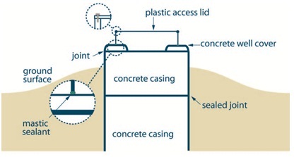
The figure is a cross-sectional view of a large diameter concrete well with a plastic access lid.
There are four components to the well; there are two concrete tiles that make up the casing, on top of which lies a concrete well cover, which has a plastic access lid.
The lower concrete tile is shown completely below ground surface. The upper concrete tile is on top of the lower tile, and it is noted that the joint between the tiles is sealed. About one-third of the upper concrete tile is above ground surface. The ground surface is highest around the well, with ground surface sloping away from the well.
The concrete well cover has a large diameter opening in the centre of the cover to facilitate access into the well casing. The plastic access lid is installed in the middle of the concrete well cover and seals the opening of the concrete well cover.
On the left side of the figure, there are two exploded views. The first exploded view is of the seal between the concrete well cover and plastic access lid, which illustrates a mastic sealant between the cover and lid. The second exploded view is of the plastic access lid, and illustrates the use of a pin or screw in the lid to prevent the top of the lid from opening.
Solid cover including access lid must be properly designed to prevent physical hazards and must be sufficiently attached to the casing to prevent surface water and other materials from entering the well.
A common type of mastic sealant material is non-toxic butyl sealant.
Figure is not to scale; all dimensions and locations are approximate. This figure does not reflect a situation where an air vent would be necessary to safely vent gas from the well site.
Figure 9-23: Well Cover Access With Concrete Lid
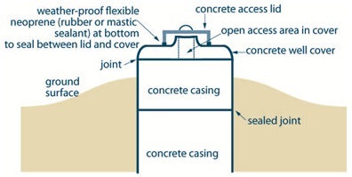
The figure is a cross-sectional view of a large diameter concrete well with a concrete access lid.
There are four components to the well; there are two concrete tiles that make up the concrete casing, on top of which lies a concrete well cover, which has a concrete access lid.
The lower concrete tile is shown completely below ground surface. The upper concrete tile is on top of the lower tile, and it is noted that the joint between the tiles is sealed. About one-third of the upper concrete tile is above ground surface. The ground surface is highest around the well, with ground surface sloping away from the well.
The concrete well cover has a small diameter opening in the centre of the cover to facilitate access into the well casing. The concrete access lid is installed on top of the concrete well cover and seals the opening of the concrete well cover. A weather-proof flexible neoprene (rubber or mastic sealant) is shown below the concrete access lid which is used to seal between the lid and cover. The access lid has a semi-circle shaped handle to lift the lid off of the cover.
Solid cover including access lid must be properly designed to prevent physical hazards and must be sufficiently attached to the casing to prevent surface water and otehr amterials from entering the well.
A common type of mastic material is non-toxic butyl sealant.
Figure is not to scale; all dimensions and locations are approximate. This figure does not reflect a situation where an air vent would be necessary to safely vent gas from the well site.
Figure 9-24: Well Cover With No Access Lid
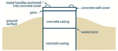
The figure is a cross-sectional view of a large diameter concrete well with a concrete well cover.
There are three components to the well; there are two concrete tiles that make up the concrete casing, on top of which lies a concrete well cover.
The lower concrete tile is shown completely below ground surface. The upper concrete tile is on top of the lower tile, and it is noted that the joint between the tiles is sealed. About one-third of the upper concrete tile is above ground surface. The ground surface is highest around the well, with ground surface sloping away from the well.
The concrete well cover does not have an opening and provides cover for the entire well casing. Two metal handles are shown as anchored into the concrete cover.
Solid cover including access lid must be properly designed to prevent physical hazzards and must be sufficiently attached to the casing to prevent surface water and other materials from entering the well.
A common type of mastic sealant is non-toxic butyl sealant.
Figure is not to scale; all dimensions and locations are approximate. This figure does not reflect a situation where an air vent would e neccessary to safely vent gas from the well site.
Reminder: The joint between the concrete well cover and the top casing shown in both Figure 9-23 and Figure 9-24 must be sealed with a mastic sealing material strip (i.e., butyl joint non toxic sealant) in areas where flooding is anticipated to occur.
Figure 9-25: Well Cover With Metal Sleeve
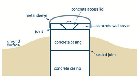
The figure is a cross-sectional view of a large diameter concrete well with a metal sleeve overtop of a concrete access lid.
There are five components to the well; there are two concrete tiles that make up the concrete casing, on top of which lies a concrete well cover, which has a concrete access lid. The lid and cover are enveloped by a metal sleeve.
The lower concrete tile is shown completely below ground surface. The upper concrete tile is on top of the lower tile, and it is noted that the joint between the tiles is sealed. About one-third of the upper concrete tile is above ground surface. The ground surface is highest around the well, with ground surface sloping away from the well.
The concrete well cover has a small diameter opening in the centre of the cover to facilitate access into the well casing. The concrete access lid is wedge-fit into the concrete well cover and seals the opening of the concrete well cover. The access lid has a semi-circle shaped handle to lift the lid off of the cover.
A metal sleeve is attached to the outside of the concrete well cover and provides a shield to the cover and lid.
Cover, including access lid and metal sleeve, must be properly designed to prevent physical hazards and must be sufficiently attached to the casing to prevent surface water and other material from entering the well.
Figure is not to scale; all dimensions and locations are approximate. This figure does not reflect a situation where an air vent would be necessart to safely vent gas from the well site.
Reminder: The joint between the concrete well cover and the top casing shown in Figure 9-25 must be sealed with a mastic sealing material strip (i.e., butyl joint non toxic sealant) in areas where flooding is anticipated to occur.
Drilled Or Other
The person constructing the well must seal the top of a well casing, that is not constructed by digging or boring, a commercially manufactured vermin-proof well cap. This includes a properly installed and sealed sanitary well seal, and a watertight and airtight well cap for a jetted or driven point well.
Reminder: Waterlines sealed to the top of the casing and to a pump under a vacuum are considered vermin-proof well caps for dewatering systems using shallow point wells.
Figure 9-26: Vermin Proof Well Cap
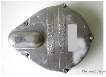
Figure 9-27: Vermin-Proof Cap And Threaded Conduit
Alternative To A Well Cap Or Cover
The Wells Regulation - The cover, cap or seal is not required if all of the following criteria are met:
- a floor has been constructed around or adjacent to the casing of the well,
- a pump (includes associated equipment such as waterlines) is installed above or adjacent to the well. (This scenario would include wells with a vertical turbine pump, hand pump or other type of pump positioned directly over the casing),
- the top of the casing is shielded in a manner sufficient to prevent entry of any material that may impair the quality of the water in the well, and
- the casing of the well is extended to at least 15 cm (6 inches) above the floor that has been constructed around or adjacent to the casing of the well.
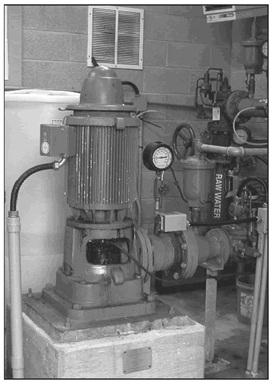
Figure 9-28: Example Of A Well Not Requiring A Cover, Cap Or Seal - Vertical Turbine Pump Installed Directly Over The Well Casing
Casing Height And Mounding
The Wells Regulation - Unless exempt, any person installing equipment in a well must ensure that the casing height, mounding and surface drainage meet requirements discussed in Chapter 7: Completing the Well’s Structure.
Well Pits
In most circumstances, well pits are not allowed to be constructed on new or existing wells.
The Wells Regulation - In only two circumstances, however, a person constructing a new well may be allowed to finish the well with a well pit. The Wells Regulation provides options for the construction of permitted well pits depending on the location of the well, the type of equipment used to construct the well and the well’s purpose. The two permitted circumstances are:
- The Wells Regulation permits the construction of a new well with a well pit as long as the well is constructed with diamond drilling equipment in connection with mineral exploration.
- The Wells Regulation permits the construction of a test hole or dewatering well with a new well pit or the addition of a new well pit to an existing test hole or dewatering well if the well is located where vehicle or pedestrian traffic is likely to pass directly over the well and the well is completed with a flush-mounted well cover in accordance with the Wells Regulation.
Along with the information provided in this section, see the “Plainly Stated” section in this chapter for further requirements and information on permitted well pits.
Well pits are usually installed at or near the time of pump and associated equipment installation in the well. The top of the well casing extends out of the floor of the well pit.
A well pit is designed to:
- contain the upper portion of a drilled well,
- prevent the upper portion of the well, and
- waterlines from freezing and allow access to the top of the well.
Well pits were the preferred choice of pump installers when installing waterlines out of the top of a drilled well to a building until the widespread use of submersible pumps, pitless adapters and pitless units began.
There are many problems associated with well pits in Ontario, such as:
- surface water can pond around the casing and above the top of drilled wells,
- large openings in the well pit’s walls can allow surface water and foreign materials to enter the pit and possibly, the top of the well, impairing the well water,
- the structure can be unsafe,
- the structure can be subject to frost heave,
- flush-mounted well pits (vaults) may be damaged by snow removal or other vehicles, and
- surface water can enter the well and cause groundwater mounding.
Reminder: A well pit is considered a confined space. There are many serious risks and hazards associated with this type of confined space including electrocution, asphyxiation, physical hazards such as drowning or falling, presence of poisonous gases and explosive gases. All required preventative measures when entering a confined space must be undertaken prior to accessing or entering any well pit. Further requirements are found in Ontario Regulation 632/05 (Confined Spaces) made under the Occupational Health and Safety Act.
Well Pit Walls (Or Casing)
The following Wells Regulation requirements apply when a new permitted well pit is constructed for a new well.
The person constructing the well must:
- consider the walls of the well pit as “casing” and
- meet the casing requirements found in Chapter 5: Constructing the Hole, Casing & Covering the Well and Chapter 7: Completing the Well’s Structure in this manual.
For example, if a permitted well pit is installed for a well, the person constructing the well must ensure that the well pit casing is:
- made of new material, unless it is scheduled to be abandoned within 180 days of completion of the structural stage,
- clean and free of contamination, and
- watertight, including any seams.
As another example, if concrete material is used as well pit casing, the person constructing the well must ensure that the:
- casing sections are properly aligned so that the joints are flush and the casing is centred,
- casing is commercially manufactured and fully cured, and
- joints between casing sections are sealed with a mastic sealing material (e.g., butyl rubber material) approved by the NSF International that remains pliable and waterproof.
Surface Drainage For A Well Pit
The following Wells Regulation requirement applies when a new permitted well pit for a new well.
The person constructing the well must ensure that surface water drainage is such that water will not collect or pond in the vicinity of, or within, a permitted well pit’s casing.
Creating And Filling The Well Pit’s Annular Space
The following Wells Regulation requirements apply when a new permitted well pit is constructed for a new well.
The person constructing the well must:
- ensure that the entire new well pit, from the bottom of the well pit to the ground surface, is constructed with a diameter that is at least 7.6 cm (3 inches) greater than the outside diameter of the well pit’s walls (or casing).
- fill any annular space outside the permitted well pit’s casing, from the bottom of the well pit to the ground surface, with suitable sealant.
- use a suitable sealant with the appropriate structural strength to support the weight of persons and vehicles that may move over the area after it is filled.
If the suitable sealant contains cement, the person constructing the well must:
- allow the cement to set according to the manufacturer’s specifications or for 12 hours, whichever is longer; and
- if, after setting, the sealant has settled or subsided, top up the cement to the ground surface.
Best Management Practice – Protection from Frost Heave for Flush-Mounted Well Pits (Vaults)
To reduce frost heave, concrete should be used as a suitable sealant in the annular space and below the flush-mounted well pit (vault). The concrete should extend at least 10 cm (4 inches) from the outside of the vault and at least 30 cm (12 inches) below the frost line
Well Pit Floor
The following Wells Regulation requirement applies when a new permitted well pit is constructed for a new well.
The person constructing the well must cover the floor of the new well pit with at least a 10 cm (4 inches) thick layer of suitable sealant that when set to a solid state will be capable of supporting the weight of a person.
Best Management Practice – Well Pit Floor
It is important that the suitable sealant used to construct the well pit floor be able to withstand the pumping of any water from the floor of the well pit. Some sealants, such as bentonite, may erode during pumping of water from the well pit’s sump, whereas properly cured concrete will not likely be removed during the pumping of water with a sump pump in any well pit sump hole.
Well Pit Cover
The following Wells Regulation requirements apply when a new permitted well pit is constructed for a new well.
The person constructing the well must cover of the well pit with a solid, watertight cover, sufficient to prevent the entry of surface water and other foreign materials into the well pit.
The following Wells Regulation requirement applies when a new permitted well pit is constructed for a new well that has been constructed with diamond drilling equipment in connection with mineral exploration.
The person constructing the well must fasten and secure the cover of the well pit in a manner that will make it difficult for children to remove it.
Keeping The Well Pit Dry
The following Wells Regulation requirements apply when a new permitted well pit is constructed for a new well that has been constructed with diamond drilling equipment in connection with mineral exploration.
Sump Pump
The person constructing the well must ensure that the new well pit is kept dry by means of a sump pump. This could also mean a sump hole would need to be installed into the floor of the well pit.
Drainage Pipe
If the water table is substantially lower than the floor of a permitted well pit, the person constructing the well may ensure that the new well pit is kept dry by means of a drainage pipe that:
- has a one-way valve to allow water to discharge from the pit but prevents surface water and other foreign materials, including insects and animals, from entering the well pit,
- passes through the layer of sealant, and
- allows water to discharge near the perimeter of the well pit.
As indicated in the best management practice titled “Well Pit Floor” in this section, the suitable sealant used to construct the well pit sump hole should be able to withstand the pumping of any water from the well pit.
Well Casing Height Above Well Pit Floor
The following Wells Regulation requirement applies when a permitted well pit is constructed with or added to a new well that has been constructed with diamond drilling equipment in connection with mineral exploration.
The person constructing the well must extend the top of the well casing at least 40 cm (16 inches) above the floor of the new well pit.
Well Cover/Seal & Vent In A Well Pit
The following Wells Regulation requirements apply when a new permitted well pit is constructed for a new well that has been constructed with diamond drilling equipment in connection with mineral exploration.
The person constructing the well must:
- seal the top of the drilled well casing inside the new well pit with a commercially manufactured sanitary well seal and
- provide an air vent line from the commercially manufactured sanitary well seal to above the cover of the new well pit.
Reminder: The top of a well inside a new well pit, including a new flush-mounted well pit (vault), must be sealed with a commercially manufactured vermin-proof cap or solid watertight well cover. A commercially manufactured sanitary well seal is considered to be a commercially manufactured vermin-proof cap. For further information on covering a well, see the “Covering the Well” section in this chapter.
Reminder: To meet the above venting requirement in a permitted well pit, the air vent may extend through the side of the well pit casing (see Figure 9-29 in this chapter).
Best Management Practice – Shield and Screen Air Vent Line on Well Pit
It is important that the well’s air vent in a well pit be shielded and screened in a way that prevents the entry of surface water and other foreign materials
The venting requirements for a drilled well completed with a well pit, and where a pump is installed in the well, are detailed in the “Venting During Pump Installation in Drilled Wells” section in this chapter.
Figure 9-29: An Example Of A Well Pit With Sump Pump And Gravity Drain Drainage
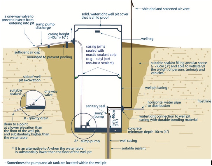
The figure is a cross-sectional view of a well inside of a concrete well pit. There are two major components to the figure; the well and its components, and the well pit and related components.
The drilled well is located at the bottom right of the well pit and below the frost line. As a minimum, the top forty centimetre portion of the well casing is exposed within the well pit, while the rest of the casing is below the bottom of the well pit. The annular space of the drilled well below the well pit is sealed with a suitable sealant.
The top of the drilled well has a sanitary seal from which two pipes extend vertically; a water pipe and an air vent. Both water pipe and air vent bend ninety degrees to the right, slightly above the well casing, and exit the well pit below the frost line. The water pipe and air vent exit the pit through a watertight connection to the well pit casing with durable bonding material. The water pipe is illustrated as remaining horizontal and extending to a distribution system. The air vent has another ninety degree bend and extends vertically through the well pit casing sealant to above ground surface. The top of the air is screened and shielded.
The well pit consists of two concrete tiles with a concrete base with a minimum thickness of ten centimetres (four inches) and a solid, watertight and child proof well pit cover. The lower concrete tile is shown completely below ground surface. The upper concrete tile is on top of the lower tile, and it is noted that the joint between the tiles is sealed with mastic sealant strip (e.g., butyl joint non-toxic sealant). About one-third of the upper concrete tile is above ground surface. The ground surface is highest around the well, with ground surface sloping away from the well. It is noted that mounding around the well is to prevent pooling of water around the well. It is further noted that the casing height above ground surface must be at least forty centimetres (sixteen inches). The well pit is constructed in an excavation which is filled with a suitable sealant and is able to withstand the weight of persons, animals, and vehicles.
On the bottom left side of the well pit, there is a water draining device (sump pump) shown. There are two options for drainage, which are detailed in Exploded Views A and B.
Exploded View A illustrates a sump pump at the bottom of the well pit. The sump pump has a discharge line that extends vertically to above ground surface, where the line bends to the left and exits the concrete tile through a watertight connection to the well pit casing. The discharge line is slightly raised above ground surface to provide a sufficient air gap, and has a one-way valve at the end to prevent insects from entering the pit.
Exploded View B illustrates a gravity drain at the bottom of the well pit. The drain has a one way valve inside the well pit. The drain exits the well pit through a watertight connection, with the drain pointing to a point at a lower elevation than the floor of the well pit. There is a note that states “B is an alternative to A when the water table is substantially lower than the floor of the well pit.”
Sometimes the pump and air tank are located within the well pit.
Reminder: Larger diameter well pits must not be entered as they are a safety hazard. Well pits must only be entered when adequate safety precautions are followed based on the Confined Spaces Regulation, Ontario Regulation 632/05 as amended under the Occupational Health and Safety Act.
Reminder: This figure is not to scale, is for illustrative purposes for this chapter only and does not necessarily represent full compliance with other requirements found in the Wells Regulation
Tools
Tables 9-4 and 9-5 provide information on drop pipes (waterlines) and other equipment installed in a well.
The Wells Regulation - Any equipment installed in the well must be clean.
| Pipe Type & Description | Diameter Range | Length Availability | Pressure Rating | Application |
|---|---|---|---|---|
| Galvanized Steel Pipe & Black Steel Pipe Black Pipe [steel pipe in which the outer diameter has been lacquered (as opposed to bare or galvanized pipe)].  |
2.5 cm (1 inch) to 20 cm (8 inches) | 6.4 m (21ft), and 3 m (10ft) lengths threaded together | 438 – 13,110 kPa (700 – 1,900 psi) |
|
PVC Pipe – Medium and High Density  |
3.2 mm (1⁄8 inch) to 61 cm (24 inches) | 30 m (100ft), 60 m (200ft), and 457 m (1,500ft) lengths | 28 - 8,487 kPa (120 – 1,230 psi) |
|
Polyethylene Pipe  |
1.9 cm (¾ inch) – 20 cm (8 inches) | Straight pipe: 12 m (40ft), 15 m (50ft), 18 m (60ft), 30 m (100ft), 90 m (300ft), 300 m (1,000ft), and 450 m (1,500ft) lengths, On Reel: up to 3,000 m (9850ft) lengths |
Up to 20,010 kPa (2,900 psi) |
|
Reminder: These drop pipes are all approved by NSF International for potable water.
| Component | Description | Graphic |
|---|---|---|
| Single Pitless Adapter |
|
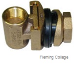 |
| Weld On Pitless Adapter |
|
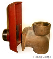 |
| Clearway Pitless Adapter |
|
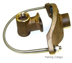 |
| Clamp On Pitless Adapter |
|
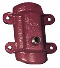 |
| Double Pipe Pitless Adapter |
|
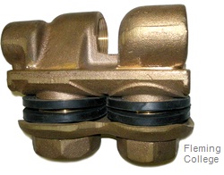 |
| Cement/Concrete Tile Pitless Adapter |
|
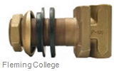 |
| Corrugated Pitless Adapter |
|
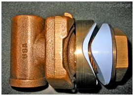 |
| Wire |
|
 |
| Link Seal |
|
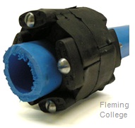 |
| Flow Control |
|
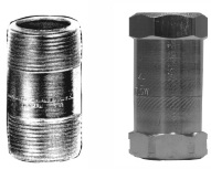 |
| Foot Valves |
|
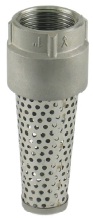 |
| Check Valves |
|
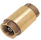 |
| Air Tight Cap |
|
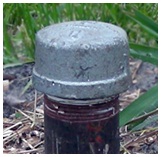 |
| Solid, Watertight Well Cover |
|
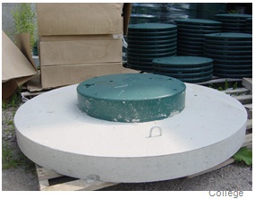 |
| Suspension Bracket (rope hanger) |
|
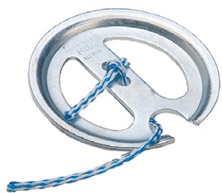 |
| Lightening Arrestor |
|
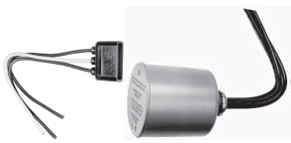 |
| Deep Well Ejector |
|
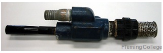 Two Pipe Deep Well Ejector
|
| Cable Guards/Cable Ties |
|
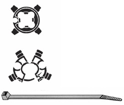 |
| Torque Arrestors |
|
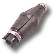 |
| Flow Inducer Sleeve |
|
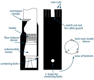 |
| Clamps |
|
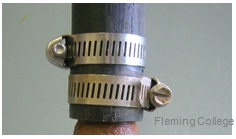 |
| Splice Kit |
|
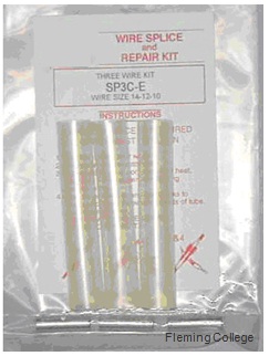 |
| Insert Adapter |
|
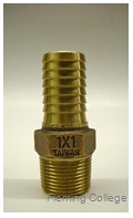 |
| Gas Trap |
|
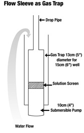 |
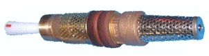
The Wells Regulation - Any equipment installed in the well must be clean.
Reminder: Always follow Manufacturer’s recommendations and guidelines with any piece of equipment.
Footnotes
- footnote[1] Back to paragraph NSF International Standard/American National Standard 61, 2008. “Water Treatment and Distribution Systems - Health Effects,” NSF International, Ann Arbor, MI 2008.
- footnote[2] Back to paragraph Sterrett, Robert J. 2007. Groundwater and Wells; Third Edition. Johnson Screens/a Weatherford Company. New Brighton, MN.
- footnote[*] Back to paragraph This pressure will maintain a column of water 10.34 m (33.9ft) high when the normal pressure in the column is relieved by the creation of a vacuum. This is the theoretical distance that water may be drawn by suction. In practice, however, centrifugal (suction) pumps should not be placed over 6 m (20ft) to 7.6 m (25ft) above the water supply and nearer if possible.
- footnote[3] Back to paragraph WSC PAS-97(04) – “WSC Performance Standards And Recommended Installation Procedures for Sanitary Water Well Pitless Adapters, Pitless Units, and Well Caps,” Water System Council, Washington DC.