Earth Energy Systems in Ontario
This technical bulletin provides an overview of Ontario’s environmental legislative framework governing the outside loop components of an earth energy system.
Prepared by:
Ontario Ministry of the Environment
March 2013
For more information:
Ministry of the Environment
Public Information Centre
Email: picemail.moe@ontario.ca
Website: Ministry of the Environment and Climate Change
© Queen’s Printer for Ontario, 2013
PIBS 7291e01
Introduction
This technical bulletin provides an overview of Ontario’s environmental legislative framework governing the outside loop components of an earth energy system. The components of earth energy systems contained inside a residence, commercial building or other structures are beyond the scope of this document.
In this technical bulletin, earth energy systems are also referred to as low temperature geothermal systems or ground source heat pumps. Earth energy systems should not be confused with high temperature geothermal systems (over 50 degrees Celsius) that obtain heat from deep within the earth to produce heat and generate electricity (e.g., Iceland’s geothermal heating system).
It is important that the siting, installation, maintenance and decommissioning of these systems be undertaken in a manner that protects public health and safety, and the environment, including groundwater and surface water. When installed in a safe manner, earth energy systems provide an excellent source of green heating and cooling for a variety of uses including residential, commercial, agricultural and industrial applications.
This technical bulletin replaces the technical bulletin titled “Constructing Earth Energy Systems in Ontario” published by the Ministry of the Environment, September 2009. It provides:
- additional information on the types of systems, including direct exchange (DX) systems that are installed in Ontario;
- possible risks associated with earth energy systems; and
- practices to mitigate such risks.
Notice: This bulletin is being provided for information purposes only and is not intended, nor should it be construed as providing legal advice in any circumstances. The applicable environmental legislation, including the following, should be consulted.
- Ontario Water Resources Act, R.S.O. 1990, c. O. 40
- R.R.O. 1990, Regulation 903 (Wells) as amended made under the Ontario Water Resources Act, R.S.O. 1990, c. O. 40
- Ontario Regulation 387/04 (Water Taking) as amended made under the Ontario Water Resources Act, R.S.O. 1990, c. O. 40
- Building Code Act, 1992, S.O. 1992, c. 23
- Ontario Regulation 350/06 (Building Code) as amended made under the Building Code Act, 1992, S.O. 1992, c. 23
- Environmental Protection Act, R.S.O. 1990, c. E. 19
- Ontario Regulation 98/12 (Ground Source Heat Pumps) made under the Environmental Protection Act, R.S.O. 1990, c. E. 19
- Ontario Regulation 463/10 (Ozone Depleting Substances and Other Halocarbons) made under the Environmental Protection Act, R.S.O. 1990, c. E. 19
- Oil, Gas and Salt Resources Act, R.S.O., 1990 c. P. 12
- Occupational Health and Safety Act, R.S.O. 1990, c. O. 1
- Lakes and Rivers Improvement Act, R.S.O. 1990, c. L. 3
- Public Lands Act, R.S.O. 1990, c. P. 43
- Conservation Authorities Act, 1990, R.S.O., c. C. 27
- Clean Water Act, 2006, S.O. 2006, c. 22
- Fisheries Act, R.S.C., 1985, c. F-14
Legislation and regulations change from time to time so it is essential that the most current versions be used. Should you have any questions about the application or interpretation of the laws of Ontario or have other legal questions, you should consult a lawyer.
All figures in this technical bulletin are not to scale and are for illustrative purposes only. They do not necessarily represent full compliance with requirements found in the legislation and regulations cited.
Any reference in this technical bulletin to an environmental compliance approval includes a certificate of approval or provisional certificate of approval issued under section 9 or 39 of the Environmental Protection Act before October 31, 2011 and an approval granted under section 53 of the Ontario Water Resources Act before October 31, 2011.
Earth Energy Systems and How They Work (1)
Earth energy comes mainly from absorbed solar energy and conducted heat from the earth’s molten interior, both stored in the overburden, rock and water of the earth. Below a certain depth, ground temperature is relatively constant all year long. Groundwater flowing through pores and fractures in soil or bedrock also has similar constant temperatures. Furthermore, surface water bodies, such as a river, pond or lake, generally exhibit less temperature fluctuation than occurs with air temperatures. Surface waters, the ground and groundwater are warmer than air temperature in winter and cooler than air in summer. An earth energy system uses the temperature differences to warm or cool buildings or other structures.
Earth energy systems are a heating and cooling system for buildings or structures that use a fluid to exchange heat with the ground or water.
An earth energy system is part of a heating, ventilation and air conditioning system (HVAC) for a building or structure. A typical earth energy system is comprised of three main components: the outside loop; the heat pump unit; and, the building’s heating or cooling unit. Generally, an earth energy system works as follows: in the winter, the outside loop obtains heat from the soil, rock, groundwater or surface water. Heat in the outside loop is transferred to a refrigerant in the heat pump unit. Heat is then dissipated from the heat pump’s refrigerant into the building’s heating or cooling unit. The reverse occurs during summer. Heat from inside the building is extracted from the building’s heating or cooling circuit. This heat is transferred to a refrigerant in the heat pump unit. Heat is then transferred to the outside loop and is released into the ground or surface water.
There are three basic types of outside loops for earth energy systems. The three types are an open loop, a closed loop and a direct expansion (DX) loop. These systems are described in sections 1.1, 1.2 and 1.3 of this technical bulletin.
There are also two types of thermal energy storage systems to exhaust heat to the ground or groundwater for heat storage and extraction. These thermal energy storage systems are described in section 1.4 of this technical bulletin.
It is estimated by the Canadian GeoExchange Coalitionv (CGC)
1.1 Open Loop Earth Energy Systems
There are three types of open loop systems which use groundwater or surface water as a heat transfer fluid. This water is circulated through a heat pump before being discharged back into an aquifer or other water body. The three forms are as follows.
1.1.1 Groundwater
Typically, groundwater is taken from a well, circulates through a heat pump and discharges to groundwater in another well, surface water, or overburden in a dry hole.
Figure 1: Example of a groundwater open loop circuit using a supply well and a discharge well
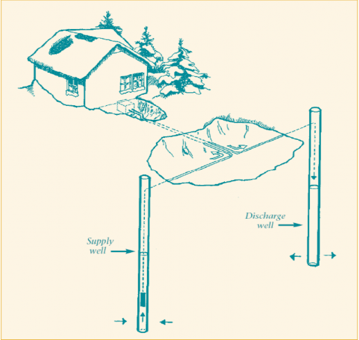
Figure 1 is a drawing showing an example of an open loop ground source geothermal system. A single story residential house is located in the upper left area of the diagram. There is an excavation in front of the house that exposes a heat pump attached to the basement of the house. Two waterlines extend from the heat pump, horizontally within the subsurface to a second excavation located in the centre-right of the diagram.
In the second excavation, one waterline turns to the left, extends through the subsurface and enters into a supply well located in the lower centre of the diagram. The supply well is represented as a vertical hole extending from the ground surface into the ground. The horizontal waterline connects to a vertical waterline in the supply well. The bottom of the vertical waterline is connected to a pump within the supply well below the groundwater level. The groundwater level in the supply well is located about the middle of the full depth of the supply well and the level is represented by an ellipse within the supply well.
In the second excavation, the second waterline turns to the right, extends through the subsurface and enters into a discharge well located on the far right side of the diagram. The discharge well is represented as a vertical hole extending from the ground surface into the ground. The horizontal waterline connects to a vertical waterline in the discharge well. The bottom of the vertical waterline ends above the groundwater level in the discharge well. The groundwater level in the discharge well is located about the middle of the full depth of the supply well and the level is represented by an ellipse within the supply well.
Arrows show groundwater is pumped out of the supply well through the waterline into the heat pump in the excavation located in front of the home. The water circulates in the heat pump where a heat transfer occurs. The diagram depicts a winter setting with snow covered trees and therefore represents heat removed from the groundwater in the heat pump to heat the residence.
After the heat transfer takes place, arrows show the water flows from the heat pump through the second waterline to the discharge well. The water discharges into the discharge well and is returned to the subsurface.
Both horizontal waterlines are shown to be buried beneath the ground surface to prevent freezing in winter.
1.1.2 Groundwater - Standing Column Well
Groundwater taken from the deep zone in the well circulates through a heat pump and discharges into the upper portion of the same well.
Figure 2: an example of a standing column well open loop circuit
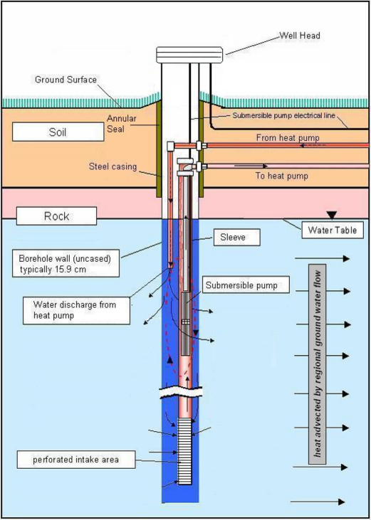
Figure 2 is a drawing showing a close up schematic of a well with a standing column geothermal system installed in it. The well is represented as a vertical hole extending from above the ground surface into the ground. The well is constructed with a steel casing that extends from above the ground surface through the overburden into the top bedrock and is constructed as an open hole (typically 15.8 cm in diameter) in the bedrock. The annular space between the steel casing and borehole is sealed to prevent flow from ground surface into the well. The well is capped with a vermin proof well cap above ground surface.
Two waterlines extend horizontally from the subsurface into the right side of the well, through the steel casing and extend vertically in the well, below the water table. The water table is located just below the bedrock surface. One waterline extends vertically though a sleeve and is connected to a submersible pump that is located below the water table in the lower portion of the well. The bottom of the sleeve contains perforations to allow the submersible pump to extract groundwater from the formation through the waterline, towards the heat pump. The second water line extends vertically in the well and stops just below the water table. Water is moved from the heat pump through the second waterline and discharged in the upper portion of the well below the water table.
Arrows show that groundwater flow is from the left side to the right side of the drawing, and that heat is advected by the groundwater flow.
Open loop systems such as a standing column well system or a system with an intake well and a discharge well, each located in a different aquifer, provide pathways for rapid groundwater movement between aquifers and in this way pose potential for impairment of the natural environment.
1.1.3 Surface Water
Surface water, taken from a lake, river or pond, circulates through a heat pump and discharges back into the surface water body.
Figure 3: example of a surface water open loop circuit
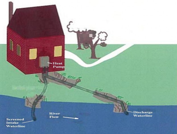
Figure 3 is a drawing showing an example of an open loop surface water geothermal system. A single story residential house is located in the upper left area of the diagram. The lower part of the diagram shows a river that flows from left to right. A heat pump is attached to the side of the house. There is an excavation in front of the house that exposes two waterlines. Two waterlines extend from the heat pump into the excavation. Both waterlines extend horizontally within the subsurface and into the river that is located in the lower area of the diagram.
The waterline on the left side of the diagram has a screened intake within the river. The waterline on the right side of the diagram is the discharge waterline. The intake waterline is up flow gradient from the discharge waterline.
Surface water is pumped through the intake waterline out of the river into the heat pump. The water circulates in the heat pump where a heat transfer occurs. The diagram depicts a summer setting and represents heat taken from the residence into the water in the heat pump to cool the residence.
After the heat transfer takes place, the water flows from the heat pump through the discharge waterline to the river. The water discharges into the river.
1.2 Closed Loop Earth Energy Systems
The outside loop of a closed earth energy system consists of a continuous sealed underground or submerged loop of tubes through which a heat transfer fluid passes and returns to the heat pump unit. The heat transfer fluid typically consists of a mixture of water, antifreeze, corrosion inhibitors and other additives. Common antifreezes used in a heat transfer system are denatured ethanol, propylene glycol and ethylene glycol. To reduce corrosion and increase lubrication, additives such as corrosion inhibitors or mineral oils are added to the heat transfer fluid. In the ground or surface water, heat moves between the heat transfer fluid and the soil, rock or water. The heat transfer fluid circulates back to the heat pump where the heat exchanges between the tube that contains the heat transfer fluid and the tube that contains the refrigerant in the heat pump unit. Generally, the outside loops for a closed loop system are installed in one of two configurations: vertical or horizontal.
1.2.1 Vertical Closed Loop
In a vertical system, a U-shaped loop of tubing is installed into drilled holes (Figure 4) which may be vertical or inclined (also referred to as angled holes). The holes are:
- backfilled with bentonite, cement or, in some cases, sand products; or
- not backfilled, i.e., left open, allowing groundwater to enter and fill the holes. If the hole is dry, potable water from another source is placed into the hole.
Figure 4: photograph of a closed vertical loop installed in a vertical borehole
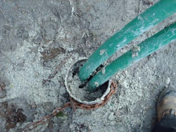
Figure 4 shows tubing placed in a vertical hole that is part of a closed loop earth energy system. At surface, the hole is held open by a temporary steel casing. The void space around the green tubing in the hole has been filled to almost the ground surface with a bentonite (manufactured swelling clay) product. The bentonite forms a seal to prevent the hole from acting as a pathway for contaminants.
Figure 5: An example of vertical closed loop system
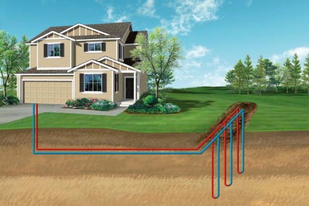
Figure 5 is a drawing showing an example of a vertical closed loop ground source geothermal system. A two story residential house is located in the upper left area of the diagram. The residence’s garage is located on the left side of the residence. Two tubes extend vertically below the garage into the subsurface. In the upper subsurface, the two tubes turn to the right and extend horizontally to an excavation on the right side of the diagram. The two horizontal tubes turn left at about 45 degrees and move horizontally in the excavation. The two tubes connect to three vertical subsurface tubing “u loops” installed into boreholes that have been drilled from the excavation. The “U loop” tubing is called a “heat exchanger”. The three vertical loops are part of one continuous tube that circulates a heat transfer fluid from the heat pump in the residence into the subsurface.
The diagram uses a red colour on one horizontal tube from the residence and the left side of the vertical U loop tubes in the ground to represent the heat transfer fluid flowing from the heat pump in the residence. The diagram depicts a summer setting, therefore, indicating that the fluid flowing from the residence contains heat. The diagram uses a blue colour on the right side of the vertical U loops and the other horizontal tube in the ground to the heat pump in the residence. The blue coloured tubing represents the heat has been transferred by conduction to the subsurface and is circulating back to the heat pump. As the heat transfer continually flows through the continuous tube, the process will repeat.
Both horizontal and vertical tubes will be buried beneath the ground surface to prevent freezing in winter.
1.2.2 Horizontal Closed Loop
In a horizontal system, the tubing is often installed into horizontal trenches that are typically excavated to a depth of 1 to 2.5 m depth below the ground surface. In some cases, a larger excavation is created to place coiled tubing into the ground. Once the tubing is placed into the excavation, the area is backfilled, initially with a material that will not puncture the tubing.
Figure 6: Photograph of horizontal closed loop partially installed
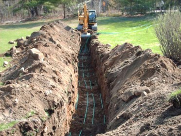
Figure 6 shows an excavator creating a trench. Green tubing in the trench will be used to carry the heat transfer fluid. (Refer to section 2.6 regarding the Occupational Health and Safety Act for worker safety.)
Figure 7: Example of horizontal closed loop system
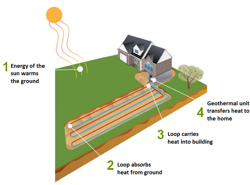
Figure 7 is a drawing showing an example of a horizontal closed loop ground source geothermal system. A two story residential house is located in the upper centre area of the diagram. Sun rays, located in the upper left of the drawing, extend to the lawn in front of the residence and warm the ground. An excavation is located below the right side of the residence exposing the basement. The excavation extends away from the residence into the lawn from the centre and lower left side of the diagram. Two tubes extend horizontally from the exposed basement into the excavation. The two tubes connect to three horizontal subsurface tubing “u loops” installed in the excavation. The “U loop” tubing is called a “heat exchanger”. The three loops are part of one continuous tube that circulates a heat transfer fluid from the heat pump in the residence into the subsurface.
The diagram uses a blue colour on one horizontal tube from the residence and the right side of the horizontal U loop tubes in the ground to represent the heat transfer fluid flowing from the heat pump in the residence. As the diagram represents a late fall scenario, the fluid flowing from the residence does not contain heat. The diagram uses a red colour on the left side of the horizontal U loops and the other horizontal tube in the ground to the heat pump in the residence. The red coloured tubing represents the heat has been transferred by conduction from the subsurface to the heat transfer fluid and is circulating back to the heat pump in the residence. As the heat transfer continually flows through the continuous tube, the process will repeat.
Both horizontal tubes will be buried beneath the ground surface to prevent freezing in winter.
The following labels are shown on the drawing: 1) the rays of the sun warming the earth; 2) the geothermal loops absorbing the warmth from the sun; 3) the loop carrying the heat into the building; and, 4) the geothermal unit (heat pump) transfers the heat into the home.
1.2.3 Surface Water Closed Loop
Surface water, such as a, river, lake or pond, may be used in earth energy systems. In some surface water closed loop systems, the tubing is installed in a coiled fashion into the water body at a minimum of two metres below the surface. Other circuits have two tubes that extend to a single modular coiled tubing unit in the surface water (See Figure 9). The modular unit is typically affixed to the bottom of the surface water body but may be floating. These systems are sometimes called submerged closed loop earth energy systems.
Figure 8: an example of a horizontal submerged earth energy system
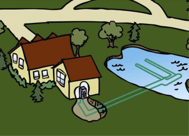
Figure 8 shows the tubing of the closed loop system placed in a coiled fashion in the pond. In many cases, separators are placed between adjacent loops to prevent chafing wear.
Figure 9: an example of a vertical submerged earth energy system.
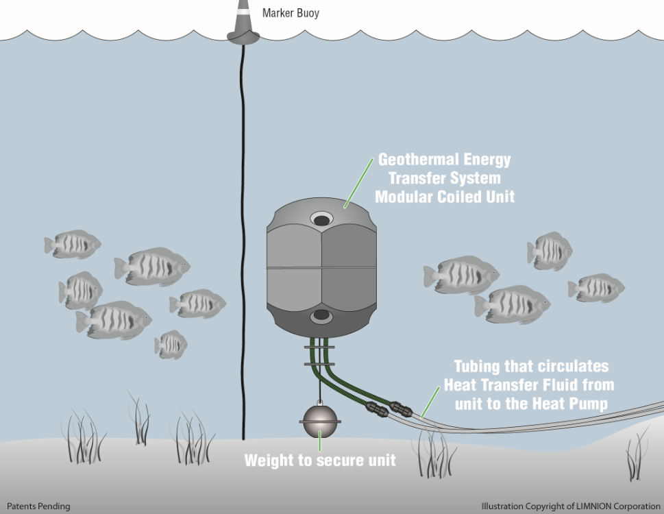
Figure 9 shows an example of two tubes extending out to a single coiled unit in the water. The tubes attach to the heat pump in the building. A heat transfer fluid circulates along the tubes between the coiled unit and the heat pump.
1.3 Direct Expansion (DX) Earth Energy Systems
A DX system is a type of closed looped system that eliminates the need for an antifreeze mixture heat transfer fluid. In DX systems, the heat transfer fluid is a refrigerant. Commonly used refrigerants and banned refrigerants are discussed in sections 2.1 and 2.5 of the technical bulletin. The refrigerant from the heat pump is circulated through a continuous loop of tubing that extends from the heat pump into the ground.
In a vertical DX system, the tubing is installed into vertical, including directional or angled, holes and backfilled with a bentonite, cement or sand product. Typically, the hole for a DX system is no more than 30 metres deep and usually is not as deep as a hole used in a closed loop system.
In a horizontal DX system, the tubing is placed in horizontal trenches that are typically excavated to about 2 to 2.5 metres in depth and then backfilled with the excavated material.
Figure 10: Example of dx closed loops within vertical and directional holes and in horizontal trenches
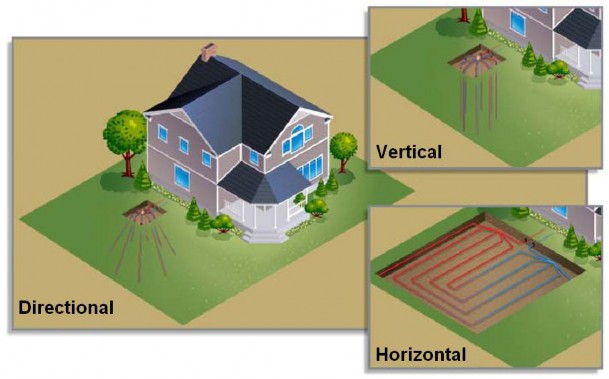
Figure 10 is a collection of three drawings showing directional, vertical and horizontal arrays of tubing loop arrays for a direct expansion geothermal system.
The main drawing shows a DX closed loop system with multiple angled subsurface loops installed in boreholes that were drilled at various angles from one location under the lawn of the home.
The second drawing shows a cluster of DX vertical loops installed in a number of vertical bore holes located equidistant along the circumference of a circle around a central point. The vertical loops are connected at the central point and form part of a continuous loop which extends from the ground into the home and back.
The third drawing shows a continuous loop of piping for a DX geothermal system installed in a back and forth pattern in the shallow subsurface.
All of the drawing show that the refrigerant flowing through the tubing from the ground to the house is at one temperature (ground temperature) while the refrigerant flowing through the tubing from the house flowing into the ground is a different temperature. (Note: The different temperature would be cooler if the system is being used for heating or warmer if the system is being used for or cooling.)
All of the drawings show the tubing buried beneath the ground surface.
1.4 Thermal Energy Storage Systems
These types of earth energy systems use vertical holes to exhaust heat to the ground or groundwater which provides a location for heat storage or extraction. Thermal energy storage systems can use an open loop or closed loop configuration to transfer the energy.
There are two common types of thermal energy storage systems in Ontario: aquifer thermal energy storage (ATES) system; and borehole thermal energy storage (BTES) system. Both the ATES and BTES systems allow for stored heat to be used at a later time or to discharge heat to cool a building or structure.
To store heat using an ATES system, warmed groundwater is returned to an aquifer in the earth and stored until it is required for heating. When required, groundwater is pumped out and heat is extracted. An ATES system largely uses groundwater as the heat transfer fluid.
To store heat in a BTES system, a continuous sealed loop of tubes, through which a heat transfer fluid passes and returns, are placed into holes in a similar fashion to a closed loop system. The heat transfer fluid is circulated within tubing, absorbing heat from the surrounding rock, soil and groundwater and storing it for use at a later time. The heat transfer fluid does not flow into or mix with the surrounding rock, soil or groundwater in the borehole.
Further information on thermal energy storage systems can be reviewed in the article “Thermal Energy Storage, A Concise Overview”, by Marc Rosen, P. Eng. GeoConneXion Magazine, 2009.
Figure 11: example of a subsurface borehole thermal energy storage system combined with a solar energy collector and above ground thermal storage used in the drake landing solar community in Okotoks, Alberta
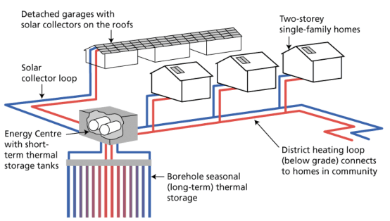
This figure is a schematic drawing showing neighbourhood solar thermal collection, geothermal storage and residential use of energy. The schematic traces the movement of heat as follows:
- Detached garages with solar collectors on the roofs.
- Solar collector loop moving heat from the solar panels to an Energy Centre.
- An Energy Centre with short term thermal storage in tanks.
- A vertical borehole geothermal system where seasonal (long-term) thermal storage occurs, and
- A district heating loop (below grade) that connects and delivers heat to the homes in the community.
Earth Energy Systems - Legislative Overview (2)
This section outlines the current pertinent legislative and regulatory framework in place to protect the environment and human health, and to address safety during the installation and use of earth energy system technology. The information from this section is summarized in Table 1.
2.1 Building Code Act and Regulation
Under the Building Code Regulation
Although the Building Code Regulation does not provide prescriptive requirements for standing column well (see section 1.1.2 of this technical bulletin) and thermal energy storage earth energy systems (see section 1.4 of this technical bulletin), it is the responsibility of the designers and contractors to design and install earth energy systems in accordance with the applicable governing CSA Standard and all other applicable laws. Under Section 8 of the Building Code Act, 1992, S.O. 1992, c. 23
If a designer chooses not to follow the prescriptive requirements of the Building Code Regulation, then the designer must propose an alternative design which meets the objectives and functional statements as stated in the Supplementary Standard SA-1 of the Building Code Regulation
The Building Code Regulation requires the construction or renovation of an earth energy system to conform to one of the following standards published by the Canadian Standards Association:
- CAN/CSA-C448.1-02, Design and Installation of Earth Energy Systems for Commercial and Institutional Buildings
footnote 17 - CAN/CSA-C448.2-02, Design and Installation of Earth Energy Systems for Residential and Other Small Buildings
footnote 18
The use and size of the building served by the earth energy system determines which of the two CAN/CSA standards applies. CAN/CSA-C448.2-02 applies to earth energy systems serving single dwelling units or buildings where the conditioned space is not more than 1400 m2, while CAN/CSA-C448.1-02 applies to systems serving all other structures.
By referencing the CAN/CSA-C448.1-02 and CAN/CSA-C448.2-02 standards, the Building Code Regulation includes requirements for the construction or renovation of groundwater and surface water open loop earth energy systems, closed loop earth energy systems, and direct exchange earth energy systems.
The CAN/CSA-C448.1-02 and CAN/CSA-C448.2-02 standards require that the void space in any holes constructed for a new closed loop or direct exchange earth energy system be filled with a grout material (sealant) to reduce the risk of a hole acting as a pathway for the downward movement of potentially contaminated surface water that may impair groundwater
If the hole is part of a closed loop vertical earth energy system, then the two standards require that the grout must be cement or bentonite, high solids clay bentonite grout in situations where the grout will not be subjected to freezing conditions, or thermally enhanced grout.
If the hole is part of a direct exchange earth energy system, then the two standards require that grout can be high solids clay bentonite grout in situations where the grout will not be subjected to freezing conditions, or thermally enhanced grout.
The two standards do not provide information on the type of grouting mixtures to use nor discuss when various types of bentonite or cement are to be placed into the hole. The standards, however, require that the contractor shall ensure that the grouting mixture is approved by the authority having jurisdiction if there are other special geological or hydrogeological conditions making a different grouting mixture more appropriate.
As a guideline, the CAN/CSA-C448.1-02 and CAN/CSA-C448.2-02 standards recommend that vertical, or inclined holes, should be properly sealed against contamination from external sources, from any contaminated stratigraphic units, or from units with poor groundwater quality that are intersected by the holes
For closed loop earth energy systems, the CAN/CSA-C448.1-02 and CAN/CSA- C448.2-02 standards ban the use of potassium acetate as a heat transfer fluid due to its corrosive properties. The standards provide other restrictions on antifreezes and additives such as corrosion inhibitors used in heat transfer fluids in order to reduce corrosion and reduce risks to the environment
For the design of a surface water or submerged closed loop system, the standards
- The physical limitation of the land area and shoreline conditions;
- The minimum disturbance to shorelines, pond, lake, or river beds, and aquatic habitat;
- Protection against wave, ice, and boat damage;
- The requirement, in some provinces, for a shoreline alteration permit from the authority having jurisdiction;
- A minimum distance of 2 m (6.6 ft) between any part of the submerged heat-exchanger system and a potable water intake;
- The type of antifreeze or inhibitor approved by the authority having jurisdiction;
- The end use of the water surface area;
- Methods for securely fastening the submerged system to the bottom, taking into consideration that this system could become coated with ice, making it buoyant; and
- Anticipated minimum water levels
For a direct exchange earth energy system, the standards
- refrigerant used be listed in CAN/CSA B52 titled Mechanical Refrigeration Code
footnote 25 ; and - heat transfer fluid underground piping and fittings;
- meet ASTM B 280-08 titled Standard Specification for Seamless Copper Tube for Air Conditioning and Refrigeration Field Service;
- meet CAN/CSA B16.22 titled Wrought Copper and Copper Alloy Solder Joint Pressure Fittings; and
- be installed in accordance with CAN/CSA B52 titled Mechanical Refrigeration Code
footnote 26 and be pressure tested at key points during the installation of the pipesfootnote 27 .
2.2 Ontario College of Trades and Apprenticeship Act (formerly regulated under the Trades Qualification and Apprenticeship Act, revoked April 8, 2013)
Effective April 8, 2013 the Ontario College of Trades and Apprenticeship Act, 2009, S.O. 2009, c. 22
Prior to April 8, 2013 similar certification and training requirements existed under the Trades Qualification and Apprenticeship Act, R.S.O. 1990, c. T. 17 (repealed April 8, 2013) (TQAA) and associated regulations
The three trades certificates relevant to the construction and installation of the external loop of earth energy systems are plumber, refrigeration and air conditioning mechanic and steamfitter. For example, a refrigeration and air conditioning mechanic’s certificate is required to hook up the tubing to the heat exchange unit.
For further information about skilled trades, the Ontario College of Trades and the Ontario College of Trades and Apprenticeship Act, 2009, please refer to the website.
2.3 Green Energy Act
The Green Energy Act, 2009 (GEA)
Ground source energy is designated under O. Reg. 15/10 made under the GEA
The effect of this designation is that a person is permitted to harness ground source energy in the manner described in O. Reg. 15/10 despite most restrictions imposed in a municipal by-law, a condominium by-law, an encumbrance on real property or an agreement. However, by-laws, instruments and other restrictions that relate to the protection of groundwater, trees, various heritage sites, or the regulating by the conservation authority of any activity or matter that is subject to a conservation authority regulation
2.4 The Environmental Protection Act (EPA)
The purpose of Environmental Protection Act
The Environmental Protection Act and its regulations define ground source heat pump systems
2.4.1 General Prohibition
Subsection 14(1) of the Environmental Protection Act states that a person shall not discharge a contaminant or cause or permit the discharge of a contaminant into the natural environment, if the discharge causes or may cause an adverse effect.
The owner or operator must report the discharge to the Ministry of the Environment’s Spills Action Centre at 1-800-268-6060. Failure to report a discharge is an offence under the Environmental Protection Act.
2.4.2 Environmental Compliance Approval
Natural gases are found with depth in several parts of Ontario. Some of these gases, such as methane and hydrogen sulphide, are explosive.
To protect public safety (i.e. the public and installers) and the environment in the event hazardous natural gas is encountered during geothermal system installation, the Ministry of the Environment identified the need for legislation to address the drilling of vertical closed loop ground source heat pumps, also known as vertical closed loop earth energy systems. This new legislation will help to reduce the risks associated with encountering hazardous gas while drilling and constructing these types of earth energy systems.
As part of the legislative changes, the Ministry of the Environment revoked and replaced Ontario Regulation 177/98 with Ontario Regulation 98/12 (Ground Source Heat Pumps) made under the Environmental Protection Act, R.S.O. 1990, c. E. 17. The government also amended Ontario Regulation 245/11 and Ontario Regulation 524/98 made under the Environmental Protection Act. The legislative requirements are as follows.
Pursuant to section 9 of the Environmental Protection Act, before a person constructs, alters, extends, or replaces a portion of a vertical closed loop earth energy system, that extends, or will extend, more than 5.0 metres below the original ground surface, the person must obtain an environmental compliance approval under Part II.1 of the Environmental Protection Act
The requirements or conditions described in an environmental compliance approval are legal requirements. The holder of the environmental compliance approval is responsible for compliance and must take measures to ensure that the activities related to installing a vertical closed loop earth energy system comply with the requirements of the environmental compliance approval.
Under the Ground Source Heat Pump Regulation (Ontario Regulation 98/12), the Ministry of the Environment can issue an approval to:
- an earth energy installer, or the installer’s business, responsible for the entire installation work on the earth energy system,
- a drilling sub-contractor, or the sub-contractor’s business, that drills the holes and installs the heat transfer tubing in the holes, or
- another party, including the owner, who wishes to apply and take responsibility for obtaining and complying with the environmental compliance approval.
The Ground Source Heat Pump Regulation outlines the requirements a person must meet to obtain a single or multi-site environmental compliance approval and to do work on a vertical closed loop earth energy system. For further information see section 2.5 of this technical bulletin.
2.5 Ground Source Heat Pumps Regulation
2.5.1 Definitions
The Ground Source Heat Pumps Regulation made under the Environmental Protection Act
- ground source heat pump
- a system that is designed to heat and cool a building or structure by using a heat-transfer fluid to exchange heat with the ground or ground water.
- hazardous gas
- means a gas or mixture of gases that,
- contains hydrocarbons (including methane), hydrogen sulphide or both,
- originates from the natural environment, and
- is present in an atmospheric concentration that may be explosive or flammable, may cause asphyxia or is otherwise hazardous;
- vertical closed loop ground source heat pump
- means a ground source heat pump that uses a continuous, sealed, underground heat exchanger consisting of subsurface tubing through which the heat-transfer fluid passes.
For the purposes of this technical bulletin, a ground source heat pump means the same thing as an earth energy system.
2.5.2 Heat Transfer Fluids
In Ontario, heat transfer fluids for closed loop and BTES earth energy systems generally contain a mixture of water and antifreeze (usually between 20 and 30 percent antifreeze
Because of the environmental concern over methanol, the Ground Source Heat Pumps Regulation bans the use of methanol as a heat transfer fluid in new closed looped earth energy systems and those that were constructed, altered, extended or replaced after June 1, 1998. As indicated in Section 2.1, the use of potassium acetate is banned by the CAN/CSA-C448.1-02 and CAN/CSA- C448.2-02 standards due to its corrosive properties. These standards are referenced by the Building Code.
Common heat transfer fluids for closed looped and BTES earth energy systems that are acceptable under the Ground Source Heat Pump Regulation include denatured ethanol, propylene glycol and ethylene glycol mixed with water. A refrigerant for a direct exchange earth energy system is also considered a heat transfer fluid under the Ground Source Heat Pump Regulation.
2.5.3 Exceptions and Exemptions from an ECA under the Ground Source Heat Pump Regulation
Ontario Regulation 98/12 establishes that the use, operation, construction, alteration, extension and replacement of an earth energy system (i.e., a ground source heat pump) are exempted from section 9 of the Environmental Protection Act, except for the following:
- The use, operation, construction, alteration, extension and replacement of a ground source heat pump that uses methanol as a heat-transfer fluid.
- The construction, alteration, extension and replacement of the portion of a vertical closed loop ground source heat pump that extends or will extend more than 5.0 metres below the level of the original ground surface
footnote 41 .
A person is not required to have an environmental compliance approval for:
- a closed loop ground source heat pump that does not extend or will not extend more than 5 metres below the original ground surface. This includes most horizontal closed loop ground source heat pump;
- an open loop ground source heat pump or a submerged (surface water) closed loop ground source heat pump;
- the portion of the ground source heat pump heating and cooling system that is found in a building or a structure such as a pool; and
- a closed loop ground source heat pump that uses methanol as a heat transfer fluid and was installed before January 1, 1998.
2.5.4 Environmental Compliance Approval Requirements
As part of an application for an environmental compliance approval, Ontario Regulation 98/12 requires that the applicant submit a work plan that is prepared by a licensed engineering practitioner or a professional geoscientist as defined in the regulation. Ontario Regulation 98/12 outlines the Ministry of the Environment’s requirements for submission of a proposed work plan as part of an application for an ECA.
See the Instructions for Completing an Application for an Environmental Compliance Approval (ECA) for Vertical Closed Loop Ground Source Heat Pumps (Draft) published by the Ministry of the Environment in June 2012 for further information on applying for an environmental compliance approval for a vertical closed loop ground source heat pump ( i.e. an earth energy system).
If hazardous gas is encountered during the construction, alteration, extension or replacement of a vertical closed loop earth energy system, Ontario Regulation 98/12 requires that the person doing the work shall, immediately and in accordance with any environmental compliance approval,
- ensure that any space around the underground heat exchanger is sealed to prevent any movement of hazardous gas between subsurface formations or between a subsurface formation and the ground surface, or otherwise manage the gas in a way that removes any potential hazard; and
- decommission the earth energy system if the measures are not taken or are taken but do not remove all potential hazards
footnote 43 .
If hazardous gas is encountered during the construction, alteration, extension or replacement of a vertical closed loop ground source heat pump, Ontario Regulation 98/12 requires that the person doing the work shall immediately give notice of the condition to,
- the local fire department;
- the occupant of the building served or to be served by the heat pump;
- the Ministry’s Spills Action Centre;
- the clerk of each municipality where the building described in clause (b) is located;
- the owner of the land on which the building served by the heat pump; and,
- the purchaser of the heat pump.
2.6 Ozone Depleting Substances and Other Halocarbons Regulation
The heat transfer fluid in the exterior loop of some earth energy systems, such as direct exchange (DX) systems, uses a refrigerant that could contain ozone depleting substances or halocarbons. Hydrochlorofluorocarbons (HCFCs) are considered to be class 2 ozone depleting substances and R-407A and R-407C are examples of halocarbons.
To help protect the natural environment from the release of refrigerants, the Ozone Depleting Substances and Other Halocarbons Regulation as amended, made under the Environmental Protection Act
The regulation defines “refrigerant” and “refrigerant equipment” as follows:
- refrigerant
- means any liquid or gas that is or that contain a class 1 ozone depleting substance, a class 2 ozone depleting substance or a halocarbon and that is used in refrigeration equipment.
- refrigeration equipment
- means an air-conditioning, heat pump, refrigeration or freezer unit, including a motor-vehicle air-conditioner, where that unit is designed to contain, contains or has contained a class 1 ozone depleting substance, a class 2 ozone depleting substance or a halocarbon.
The regulation establishes that no person shall discharge or permit the discharge of refrigerant that is or that contains a class 2 ozone depleting substance or a halocarbon into the natural environment or within a building
If a person discharges or causes or permits the discharge of 100 kilograms or more of refrigerant into the air within a building or into the natural environment, then under the Ozone Depleting Substances and Other Halocarbons Regulation the person is required to report that discharge to the Ministry of the Environment as soon as reasonably possible after the discharge occurs
Subsection 22(1) of the above noted regulation requires that no person shall service or test refrigeration equipment that contains a refrigerant unless the person is certified under section 34 and,
- the person or his or her employer owns equipment that is capable of collecting and capturing the refrigerant; or
- the person or his or her employer has a written contract with a person who owns equipment that is capable of collecting and capturing the refrigerant and the contract provides for immediate access to that equipment.
2.7 The Ontario Water Resources Act (OWRA)
The purpose of Ontario Water Resources Act, R.S.O. 1990, c. O. 40
The Ontario Water Resources Act and some of the regulations made under the Act, provide requirements for “wells”, for the taking of water, and for the discharging of material directly or indirectly into the environment. Many of these requirements apply to earth energy systems that use groundwater or surface water.
2.7.1 General Prohibition
It is an offence under subsection 30(1) of the Ontario Water Resources Act for a person to cause or permit the discharge of any material of any kind into the natural environment that may impair the quality of any waters.
2.7.2 Permit to Take Water
To protect, conserve and manage water resources, the Ministry of the Environment administers and enforces a permit program for the taking of water.
If an open loop or ATES earth energy system for a commercial or industrial building is taking water at a volume of more than 50,000 litres on any one day from a well, a mine or a surface water body, then section 34 of the Ontario Water Resources Act requires that a Permit to Take Water
If, during the construction of any earth energy system, a person will be dewatering or testing the water at a volume of more than 50,000 litres on any one day, then a Permit to Take Water must first be obtained from the Ministry of the Environment as detailed in the Water Taking Regulation. Groundwater examples include the following:
- If a well, hole or trench intersects groundwater and more than 50,000 litres of water in a day is being removed out of the hole during the construction process, then the person constructing the well, hole or trench must have a valid Permit To Take Water.
- If a person conducts a pumping test on a well to determine the yield of the well or aquifer and the person pumps more than 50,000 litres of water in a day, then the person must have a valid Permit To Take Water.
Also, if a water taking of any amount causes interference with any private or public interest in the water, a Director may prohibit a person from taking the water without a permit issued by the Director
Circumstances where a person could take more than 50,000 litres of water or cause interference with any private or public interest in the water include:
- flowing conditions encountered during the drilling of the hole,
- flowing conditions that persist or commence at a later time, such as during operation of the earth energy system or after abandonment,
- the taking of water from a well that is part of an open loop or ATES earth energy system for a commercial or industrial building, or
- groundwater discharges from a hole during the construction of a closed loop earth energy system.
Where a person has committed an offence under section 34 of the Ontario Water Resources Act, a designated Director or Provincial Officer under the Ontario Water Resources Act may, among other things, order the person taking the water to:
- stop the taking or discharge and to obtain a Permit To Take Water
- obtain a Permit To Take Water, or
- stop or regulate the taking
A permit to take water is not required for a taking from a domestic open loop ground source unless the taking does not meet the purpose of the Ontario Water Resources Act. If the taking does not meet the purpose of the Act (e.g., does not protect, manage or conserve waters) the Director can require the taking be stopped and require the owner to obtain a permit to take water. An example of not meeting the purpose of the Act could be the taking interferes with another person’s well.
A Permit To Take Water is generally not required for the operation of a closed loop, DX or BTES earth energy system used to heat or cool an industrial commercial building because, although tubing is installed into the hole or surface water body, no water is being taken.
2.7.3 Discharging Water and Sewage Works Approvals
To help protect waters from discharges that may cause impairment, the Ministry of the Environment administers and enforces a sewage works environmental compliance approval program.
Pursuant to section 53 of the Ontario Water Resources Act
Closed loop or direct exchange earth energy systems are not designed to discharge water or other material into the environment, therefore, a sewage works environmental compliance approval is not required for the operation of a closed loop or direct exchange earth energy system as these systems are designed to keep the heat transfer fluid or refrigerant within the tubing.
You may however, require an environmental compliance approval during the construction of a closed loop or direct exchange earth energy system if, during this period, water is being discharged directly or indirectly into a ditch, drain or storm sewer or a well, lake, river, pond, spring, stream, reservoir or other water or watercourse.
2.7.4 “Wells” under the Ontario Water Resources Act
Improperly constructed or poorly maintained wells can act as direct pathways for contaminants to enter groundwater or for mineralized water or gas bearing formations to impair groundwater that could be used for drinking water.
During installation of earth energy systems, holes are made in the ground. Some of these holes may meet the definition of “well” in the Ontario Water Resources Act
Subsection 1(1) of the Ontario Water Resources Act defines a “well” as:
a hole made in the ground to locate or to obtain ground water or to test or to obtain information in respect of ground water or an aquifer, and includes a spring around or in which works are made or equipment is installed for collection or transmission of water and that is or is likely to be used as a source of water for human consumption.
The Wells Regulation further defines two types of “wells”, the “test hole”
A test hole means a “well” that,
- is made to test or to obtain information in respect of groundwater or an aquifer, and
- is not used or intended for use as a source of water for agriculture or human consumption;
A dewatering well means a “well” that is not used or intended for use as a source of water for agriculture or human consumption and that is made,
- to lower or control the level of groundwater in the area of the well, or
- to remove materials that may be in the groundwater;
The determination of whether a hole is or is not a “well” is based on the purpose of construction of the hole. For example, a hole is a “well” if it is made to:
- locate groundwater,
- obtain groundwater, or
- conduct a test on the groundwater in the hole or obtain information on groundwater or an aquifer.
When constructing an open loop or aquifer thermal energy storage (ATES) system with vertical holes, the person constructing the hole should consider the following:
- A hole from which groundwater is obtained falls within the definition of a well under the Ontario Water Resources Act.
- If water is discharged from a heat pump back to the same aquifer or another aquifer through another hole that was constructed to locate or test ground water, then the second hole is also considered to be a “well”.
If during the construction of a closed loop, direct exchange, or borehole thermal energy storage (BTES) system a person performs the following activities, then the hole will meet the definition of a “well” as defined by the Ontario Water Resources Act:
- Conducts a test on the groundwater in the hole. This would include any hole that is tested and would eventually be used to hold heat transfer tubing. A test on the groundwater would include:
- measuring a groundwater level in the hole,
- field testing the quality, including tasting and smelling, of the groundwater,
- obtaining a water sample of the groundwater for laboratory analysis,
- conducting a short duration pumping test in the hole,
- conducting hydraulic conductivity tests, including rising or falling head tests in the hole, or
- conducting thermal conductivity tests of the groundwater to determine the groundwater’s temperature.
- Obtains information on the groundwater or an aquifer intercepted by the hole. This would include any hole where the person obtains the above information and eventually uses the hole to hold heat transfer tubing. Obtaining information on the groundwater or an aquifer would include recording the depth of groundwater while drilling.
- Locates and dewaters groundwater for the purposes of lowering the groundwater level in other nearby holes. This would include any hole that is used to lower the groundwater level and is then used to hold heat transfer tubing.
- Locates and uses groundwater in a hole that may be used to conduct heat from a heat transfer fluid circulating through tubing within the hole. This would include any vertical or closed loop earth energy system installed below the water table in a vertical hole.
In a closed loop, direct exchange or BTES earth system, the hole is not considered to be a “well” under the Ontario Water Resources Act, if a person creates the hole solely to install the loop of heat transfer tubes.
There are other systems and scenarios that are not discussed above. Each scenario needs to be evaluated on its own merits to determine whether or not a hole is a “well” as defined in the Ontario Water Resources Act.
A “well”, including any well that is part of an earth energy system, and is not otherwise exempt, must be constructed by a person who holds a valid well technician licence of the correct class and also holds a valid well contractor licence or who works for the holder of a valid well contractor licence. Further guidance is found in Chapter 3 of the Water Supply Wells - Requirements and Best Management Practices manual published by the Ministry of the Environment, December 2009.
The person constructing the “well” must meet all of the requirements found in the Wells Regulation such as requirements for well siting and construction.
2.8 Wells Regulation
If a hole excavated for an earth energy system which meets the definition of “well” under the Ontario Water Resources Act, then the requirements of the Wells Regulation
The Wells Regulation sets well construction, maintenance, tagging, notification, well record and abandonment requirements and imposes well licensing requirements for various well construction activities. These requirements are intended to provide a multiple barrier approach to reduce the risk of a well acting as a pathway for contaminants to migrate along and impair groundwater.
If the hole is considered to be a “well” under the Ontario Water Resources Act and the person wishes to use the well for a closed loop or direct exchange earth energy system, then the well owner must first abandon or overdrill the well in accordance with the Wells Regulation
If the hole is considered to be a “well” under the Ontario Water Resources Act and:
- mineralized water is encountered, the well owner must immediately abandon the well in accordance with the Wells Regulation, with some exceptions, outlined below
footnote 58 . - natural gas is encountered, the well owner must take steps to manage the gas in a way that prevents hazardous gas impacts or immediately abandon the well
footnote 59 .
The abandonment requirement for mineralized water does not apply to some wells such as a test hole or dewatering well. In some circumstances, a written consent not to abandon a well may be issued by the Wells Director at the Ministry of the Environment. Further guidance is found in Chapter 14 of the Water Supply Wells - Requirements and Best Management Practices manual published by the Ministry of the Environment, December 2009.
Clarification of the Wells Regulation requirements for water supply wells can be found in the Water Supply Wells - Requirements and Best Management Practices manual published by the Ministry of the Environment in December 2009
2.9 Occupational Health and Safety Act
To protect the health and safety of workers, the installation, repair and maintenance of earth energy systems must be done in accordance with the Occupational Health and Safety Act (OHSA)
2.10 Fire Protection and Prevention Act
To prevent fires and explosions, the Fire Protection and Prevention Act
2.11 Clean Water Act
The Clean Water Act
There are a number of ways that new or existing earth energy systems may be considered in source protection assessment reports and affected by source protection plan policies. Specifically, closed loop and direct exchange systems may be identified locally as a threat to the quality of drinking water and they could be considered a transport (preferential) pathway for contamination to a source of drinking water. Transport pathways may affect the vulnerability of the immediate surrounding area, potentially increasing the risk posed by nearby activities. Also, open loop systems that withdraw water from a well may be identified as a risk to water quantity and as a transport pathway for contamination to a source of drinking water.
Earth energy systems that are identified in the local assessment report as posing a significant threat to water quality or quantity may be subject to policies to manage the threat or that prohibit the earth energy system from being located in a particular area. If an earth energy system is considered a transport pathway, a nearby activity that might otherwise not pose a significant risk to drinking water could be subject to a range of policies to address the activity.
Source protection plan policies may also be included to suggest strategic actions for transport pathways within wellhead protection areas and surface water intake protection zones to ensure the transport pathway will cease to endanger the raw water supply of a drinking water system. For example, if a Source Protection Committee has reason to believe that a restriction on an earth energy system is needed to protect source water, then the committee can suggest that a local municipality pass a by-law or planning approval to restrict the location of an earth energy system. Municipalities are also empowered to take such actions directly, outside of the source protection planning process. For further information, refer to “Section 2.3 - Green Energy Act” of this technical bulletin.
2.12 Federal Fisheries Act
The federal Fisheries Act
The Fisheries Act may also apply to shoreline works for all earth energy systems that have the potential to impact fish or fish habitat. Information on Fisheries Act requirements can be obtained from Fisheries and Oceans Canada (DFO).
2.13 Public Lands Act and other Legislation Relevant to Surface Water
Authorizations (work permits) and tenure (land use occupational authority) under the Public Lands Act
In some scenarios, work permits and tenure are not required for activities that may be associated with the installation of an earth energy system.
Tenure is not required for:
- Thermal lake loops (heat loops) located (placed on the surface of the lake bed) in front of the owner’s property (PL 3.03.01 Free Use Policy).
A work permit is not required for:
- Dredging that is undertaken for the installation of service cables, heat loops or water intakes for use by private residences (PLA O. Reg. 453/96).
Approval under the Lakes and Rivers Improvements Act (LRIA)
Please consult with the local MNR district office to determine what authorizations or tenure requirements may apply to a specific project. Note that this is not an exhaustive list of legislation and regulations administered by MNR that may apply.
2.14 Conservation Authorities Act
Under the Conservation Authorities Act
Under Section 28 of the Conservation Authorities Act, conservation authorities also regulate activities that may change or interfere in any way with the existing channel of a watercourse or change or interfere in any way with a wetland. The regulated areas include hazardous lands such as unstable soils (Leda clay, organic soils) and unstable bedrock (karst), wetlands, areas adjacent to wetlands, shorelines and areas susceptible to flooding and associated allowances, i.e. areas adjacent or close to the shoreline of the Great Lakes-St. Lawrence River System, connecting channels or to inland lakes, river or stream valleys, (including valleylands) and watercourses as defined under the Act.
Before installing an earth energy system in a river or stream valley, a watercourse, a wetland, Great Lakes or a lake shoreline or in hazardous lands within conservation authority jurisdiction, you should check with the local conservation authority to determine if a permit is required under section 28 of the Conservation Authorities Act.
To find out what legislative and regulatory requirements may apply, prior to doing work in or on the bed of a water body or near or adjacent to a shoreline or shorelands area, check with the local Ministry of Natural Resources District Office, or local conservation authority. See the end of this technical bulletin (Section 4.0) for contact information.
2.15 The Oil, Gas and Salt Resources Act
Under subsection 1(1) of the Oil, Gas and Salt Resources Act
a hole in the ground, whether completely drilled or in the process of being drilled, for the purpose of,
- the production of oil, gas or formation water, including the production of coal bed methane but excluding the production of fresh water,
- the injection, storage and withdrawal of oil, gas, other hydrocarbons or other approved substances in an underground geological formation,
- the disposal of oil field fluid in an underground geological formation,
- solution mining, or
- geological evaluation or testing rocks of Cambrian or more recent age.
Holes drilled into Paleozoic bedrock to collect geological information as required by CAN/CSA-C448.1-02, Design and Installation of Earth Energy Systems for Commercial and Institutional Buildings may be considered a “well” under the Oil, Gas and Salt Resources Act. Where a hole is considered a “well” under the Oil, Gas and Salt Resources Act, the person constructing the well must obtain a well licence under the Act.
Persons installing earth energy systems should consult with the Petroleum Resources Centre of the Ministry of Natural Resources located in London, Ontario, telephone: 519-873-4634 or MNR website for further information before construction of the system commences.
2.16 Other Provincial Legislation
Certain installation and maintenance work pertaining to or associated with earth energy systems may be subject to additional legislative and regulatory controls. Other requirements may include, but are not limited to:
- Permit and inspection requirements under the Electricity Act, 1998, S.O. 1998. c. 15, Schedule A;
- Planning decisions including the supply, efficient use and conservation and protection of ecosystems under Planning Act, R.S.O. 1990, c. P. 13; and,
- Permit requirements under Dangerous Goods Transportation Act, R.S.O. 1990, c. D. 1
Recognizing and Minimizing Risks (3)
There are potential environmental risks associated with earth energy systems. Some of these risks could include fluid and gas migration of fluids, gas and other contaminants along preferential pathways; erosion and contamination by discharge water; and possible adverse effects of temperature imbalances. The legislative and regulatory requirements outlined in section 2 of this bulletin help to protect against environmental risks posed by earth energy systems. Additional information is provided in this section to assist people in recognizing environmental risks and to help further protect the environment and the health and safety of Ontarians.
3.1 Vertical Holes
The discussion in this section applies to all vertical holes, including open loop, closed loop, direct exchange, and angled (or inclined) holes.
Many earth energy systems have vertical or angled holes that could allow direct access from the ground surface to groundwater resources used for drinking water. There is the potential for a hole used in the loop of an earth energy system to act as a “preferential flow pathway” for contaminants, natural gas, mineralized water and other foreign materials to move between groundwater zones or between the ground surface and the groundwater. Transport along preferential pathways can result from improper siting, construction, maintenance or abandonment of holes that intersect one or multiple aquifers and other subsurface formations.
3.1.1 Siting Vertical Holes
Siting an earth energy system near a source of contamination increases the risk of the contaminant moving along a hole and potentially impairing groundwater, surface water or drinking water wells. Siting considerations including minimum setback distances from contamination sources, property boundaries, buildings, other earth energy systems, drinking water wells and surface water bodies:
- if applicable, must meet the minimum legal requirements such as the Wells Regulation and
- if no legal requirements exist, should be set according to advice from a professional geoscientist
footnote 71 or professional engineerfootnote 72 . As a sound practice, the professional geoscientist or professional engineer should consider the minimum siting requirements found in Chapter 4 of the Water Supply Wells - Requirements and Best Management Practices Manual published by the Ministry of the Environment, December 2009footnote 73 .
3.1.2 Constructing Vertical Holes
Earth energy systems that use vertical or inclined holes can extend deeper than most drilled water wells.
Groundwater in sedimentary bedrocks is frequently salty or sulphurous, particularly at greater depths. Oil and gas deposits also reside within these rocks. In some circumstances, oil and gas have migrated into the overlying overburden. Mineralized water, gas and oil can migrate along open holes associated with an earth energy system and impair other fresh groundwater zones.
Artesian flow of water onto the ground surface is difficult to control and can result when zones where groundwater is under pressure are encountered in overburden or bedrock formations. Uncontrolled flow from a well or from a hole that is constructed for a vertical closed loop earth energy system can cause flooding problems or sink holes.
Open loop systems such as a standing column well system or a system with an intake well and a discharge well, each located in a different aquifer, provide pathways for rapid groundwater movement between aquifers and in this way pose a risk of environmental impairment.
The requirements in the Wells Regulation and Building Code Regulation address some concerns associated with drilling holes (see section 2 of this technical bulletin for further information on the Wells Regulation).
Also, as mentioned earlier, the Ground Source Heat Pumps Regulation (Ontario Regulation 98/12) provides specific requirements for vertical closed loop geothermal systems to address concerns about encountering hazardous gas in drilled holes. This section addresses other risks, not covered in Ontario Regulation 98/12.
A licensed engineering practitioner
- the local geology including well records from the Ministry of the Environment,
- oil and gas well records and other information found in the Oil, Gas and Salt Resources Library of the Ministry of Natural Resources,
- Assessment Reports prepared under the Clean Water Act, and
- area hydrogeological reports to determine the likelihood of encountering oil, gas or mineralized water at proposed drilling depths when drilling into bedrock formations.
Earth energy system designers should consider the following:
- If oil is expected to be encountered, design and construct each hole to the requirements of the Oil, Gas and Salt Resources Act and its regulations and standards, as a minimum, including the use of blow-out prevention or gas diversion equipment.
- The guidance for constructing wells in Chapter 12 of the Water Supply Wells - Requirements and Best Management Practices manual published by the Ministry of the Environment, December 2009
footnote 76 at locations where artesian head elevation is potentially above ground surface and water may flow at surface. - CAN/CSA-C448.3-02 standard, Design and Installation of Underground Thermal Energy Storage Systems for Commercial and Institutional Buildings for designing ATES and BTES earth energy systems.
Persons constructing holes or installing equipment should be trained, experienced, equipped and, if necessary, licensed to use the equipment and materials for installing an earth energy system in a specific environment. For example, if a person is constructing holes in artesian aquifers that could cause uncontrolled flows at surface, the person:
- should have past experience in stopping the flow of water from the holes,
- must, where the hole is a well as defined under the Ontario Water Resources Act, hold a valid well technician licence of the appropriate class, and
- must, where the hole is a well as defined under the Ontario Water Resources Act, hold or work for the holder of a valid well contractor licence.
If contamination, such as a hazardous waste, is encountered during the construction of a hole associated with an earth energy system, the person constructing the hole should stop work immediately to reduce serious dangers to the site crew, well owner and the environment. If the hole is a “well” as defined in the Ontario Water Resources Act and to meet the obligation of reporting natural gas to the Director, the person constructing the well can contact the Ministry of the Environment through the Ministry’s Spills Action Centre (SAC) at 1-800-268-6060. The SAC is available to take calls 24 hours a day, every day of the year.
Depending on circumstance, the Ministry of the Environment can offer assistance and notify other interested agencies to help reduce dangers to the site crew, well owner and the environment.
After heat transfer fluid tubing is installed in a hole for a closed loop, direct exchange or BTES system, a material is usually placed in the hole to fill the remaining void space. In order for the earth energy system to function, the material needs to conduct the heat between the heat transfer fluid located within the tubing and the earth.
In many older systems and some new systems, some or all of the material used in the void space of the vertical hole is sand, gravel or drill cuttings. In some other cases, the void space is left unfilled to allow groundwater to be used for thermal convection. For all of these systems, the vertical holes are preferential flow pathways along which fluid and gas may migrate and pose an environmental risk.
The void space in each hole that is part of an earth energy system should be sealed at the time of construction with a material than can stop the vertical migration of fluids or gases while offering the best heat transfer. Placement of a sealing material in the entire void space in the hole at the time of initial construction can also help the owner significantly reduce the cost of properly sealing the hole at the time of decommissioning (i.e. proper abandonment). The most common sealing products are bentonite (manufactured swelling clay) and cement. Each product has different properties. Sealing materials and the water that is mixed with those materials must not impair the quality of the groundwater. Site conditions and system design should be carefully considered when choosing a sealant. For example, some manufacturers and installers of systems require:
- The use of a specialized heat resistant cement to reduce shrinkage cracks from thermal changes.
- The use of a sulphate resistant cement if hydrogen sulphide gas or sulphur water is present.
- The use of product other than bentonite if uncontrolled flows at surface or elevated salty water are present.
Some general bentonite or cement advantages and disadvantages are found in Table 6-2 of Chapter 6 of the “Water Supply Wells - Requirements and Best Management Practices manual” published by the Ministry of the Environment, December 2009
In closed loop, direct exchange, and BTES systems using vertical holes, the hole diameter is typically 10.2 centimetres or smaller. Spacers are used between the U-loop tubing. The small diameter holes and spacers allow the heat transfer fluid tubing to increase conductivity between the earth and the heat transfer fluid. The use of spacers also avoids tubing overlap and consequent thermal interference. The lack of a sealant between the pipe and side of the hole, however, increases the risk of the hole acting as a pathway for contaminants. To reduce the risk of the hole acting as a pathway, a person should consider:
- Lining and sealing the hole with a steel, plastic or geo-textile casing and sealant, and
- If the tubing is rigid enough, then attaching spacers and centralizers to the pipes or tubes that prevent the pipes or tubes from touching the walls of the hole, and
- Using a bottom up placement technique such as pressure grouting, place a proper sealant for the environment into the void space of the hole.
3.2 Surface Water
Often, a near shore
In order to prevent a violation of the federal Fisheries Act, contact should be made with the local conservation authority, or the Department of Fisheries and Oceans office in the area. Parks Canada should also be contacted if the project is located within its jurisdiction (including the Trent Severn Waterway and the Rideau Canal).
3.3 Heat Transfer Fluid including Refrigerant
Depending on the type of antifreeze and site-specific environmental conditions, a heat transfer fluid from an earth energy system may cause an adverse effect to the natural environment, impairment to groundwater or surface water, damage to property and a safety risk (e.g. fire) to owners, operators and workers if the tubing ruptures. Examples include:
- Ethanol (denatured ethanol) is flammable, corrosive, a health hazard and can have a potential environmental risk.
- Ethylene glycol and propylene glycol have potential to be an environmental risk to surface water bodies and groundwater.
- Additives to heat transfer fluids can include biocides, anti-corrosives, flow enhancers, and machine oil (to lubricate the pump) may degrade the environment.
Refrigerants commonly used in DX systems include R-410A and R-407C.
Copper piping is commonly used for DX systems. In corrosive environments and in the vicinity of the water table, copper piping without cathodic protection may crack or corrode and allow for an uncontrolled discharge of refrigerant. If used in closed loop systems, lower density polyethylene tubing also has an increased risk of degradation and cracking.
In addition to meeting all of the legislative and regulatory requirements outlined in Section 2 the following should be considered to help reduce the risk of leaks, or other releases of these substances:
- that all persons installing tubing for closed loop, DX BTES earth energy systems, at a minimum, ensure the tubing meets the CAN/CSA C448-02 standard including pressure testing at key points during the installation.
- that all persons be properly trained to install, maintain and repair earth energy systems and if using ethanol, they follow the information found in:
- The Health and Safety Advisory, Geothermal Systems: Ethanol and Ethanol/Water Mixtures, published by the Infrastructure Health and Safety Association and Developed in Association with the Ontario Ministry of Labour
footnote 79 . - The Technical Information Note titled Safe Operating Procedure for Handling Ethanol published by the Canadian GeoExchange Coalition and Heating, Refrigeration and Air Conditioning Institute of Canada (HRAI).
footnote 80
- The Health and Safety Advisory, Geothermal Systems: Ethanol and Ethanol/Water Mixtures, published by the Infrastructure Health and Safety Association and Developed in Association with the Ontario Ministry of Labour
3.4 Properly Decommissioning an Earth Energy System
Under the Ground Source Heat Pumps Regulation, there are regulatory requirements for decommissioning a vertical closed loop earth energy system when “hazardous gas” is encountered.
Also, the person abandoning a “well” for an open loop system must meet the plugging and sealing requirements prescribed in sections 21 and 21.1 of the Wells Regulation.
In addition to the above requirements in this section, if an earth energy system is not being used or maintained for future use, then the owner should consider the following actions in this section of the technical bulletin.
Proper decommissioning of an earth energy system mitigates potential hazards and helps to protect the environment from potential contaminant migration along preferential pathways and from discharges of heat transfer fluid. With abandoned systems involving vertical holes, both the loop piping and the holes can act as preferential pathways for the migration of contaminants if not properly decommissioned.
Detailed documentation of the original installation is helpful in determining the best course of action to properly decommission an earth energy system including removing the heat transfer fluid and plugging the earth energy system. Annex A of the CAN/CSA-C448-02 suggests the design documentation, including the type of heat transfer fluid being used, be provided to the owner of the system.
Vertical holes in some systems may intersect oil, mineralized groundwater or flowing conditions.
To reduce the risk of oil, mineralized water or flowing groundwater problems, an owner should retain a professional engineer or professional geoscientist experienced in hydrogeology, earth energy systems and, where warranted, petroleum resources before proceeding with the decommissioning of an earth energy system.
The retained professional engineer or professional geoscientist should conduct a geological study of the area before decommissioning commences.
The retained professional engineer or professional geoscientist should design the decommissioning of an earth energy system, which may include the drilling out of the tubing and then filling of these holes, based on the information obtained from the study and the minimum standards and requirements found in:
- Oil, Gas and Salt Resources Act, R.S.O. 1990, c. P. 12, its regulations and its standards.
- Oil, Gas and Salt Resources Act, Provincial Operating Standards, Version 2.0, 2002 published by the Ministry of Natural Resources including the use of blow-out prevention and gas diversion equipment and a cement grout that is resistant to the formation and is resistant to heat.
- The Wells Regulation and Chapter 15 of the Water Supply Wells - Requirements and Best Management Practices Manual published by the Ministry of the Environment, December 2009.
- Annex A (Informative) of the CAN/CSA-C448.1-02, Design and Installation of Earth Energy Systems for Commercial and Institutional Buildings Design and Installation of Earth Energy Systems, CAN/CSA C448 Series- 02, A National Standard of Canada, originally published February 2002, reprinted October 2009, prepared by Canadian Standards Association, ISBN 1-55324-844-9. Annex A provides additional environmental guidelines to reduce potential environmental risks associated with earth energy systems.
The retained professional engineer or professional geoscientist should, if necessary, determine the type of drilling fluids with additives that need to be used during the re-drilling of the tubing to counterbalance formation pressure to prevent water from entering the hole prematurely.
The person decommissioning the earth energy system should have the experience and training to deal with any identified contamination, flowing water and, if necessary, with hazardous gas to the standards set out in Oil, Gas and Salt Resources Act, R.S.O. 1990, c. P. 12, its regulations and its Provincial Operating Standard.
The person decommissioning the earth energy system should implement the design of the professional engineer or professional geoscientist and works under the supervision of the professional engineer or geoscientist.
If the system uses a heat transfer fluid, experienced professionals should carefully remove, store and then dispose of the heat transfer fluid in accordance with the requirements of the Environmental Protection Act and its regulations
If an earth energy system includes any wells as defined in the Ontario Water Resources Act, the Wells Regulation sets out certain times or events when a well, as defined in the Ontario Water Resources Act, must be properly abandoned. Chapter 14 of the Water Supply Wells - Requirements and Best Management Practices Manual published by the Ministry of the Environment, December 2009
Chapter 15 of the Water Supply Wells - Requirements and Best Management Practices Manual published by the Ministry of the Environment, December 2009
Additional Sources of Information and Links (4)
A copy of the various legislation and regulations can be obtained from the E-Laws website.
A copy of the Water Supply Wells - Requirements and Best Management Practices manual can be obtained from the Ministry of the Environment’s website.
The publications are also available by calling the Ministry of the Environment’s Public Information Centre at 1-800-565-4923 or 416-325-4000.
A directory of licensed well contractors is available online.
For further information about earth energy systems, source water protection and spills the nearest Ministry of the Environment office listed in the blue pages of the telephone directory can be contacted. General information is also available at the Ministry of the Environment’s Public Information Centre at 1-800-565-4923 or (416) 325-4000. Visit Ministry of the Environment’s website.
A copy of the CAN/CSA-C448 Series 02 titled Design and Installation of Earth Energy Systems can be ordered through the Canadian Standards Association, 5060 Spectrum Way, Suite 100, Mississauga, Ontario L4W 5N6, telephone 1-800-463-6727.
A copy of the Supplementary Standard SA-1 is found in Volume 2 of the 2006 Building Code Compendium. A copy of the 2006 Building Code Compendium, Published by the Ministry of Municipal Affairs and Housing, Publication Number 510097 can be ordered through Service Ontario.
For further information about Trades regulation and requirements can be obtained from the Ministry of Training, Colleges and Universities, Programs Branch, at 416-314-4350 or 416-212-9255.
Information about the Ontario College of Trades and the Ontario College of Trades and Apprenticeship Act, 2009, can be obtained from their website.
More information on Permits to Take Water can be found at: Permits to Take Water
A guide explaining the sewage works process is available at: Design Guidelines For Sewage Works.
Information on Ontario Regulation 98/12 (Ground Source Heat Pumps) and applying for an environmental compliance approval for construction of a vertical ground source earth energy system can be found at Ontario’s Regulatory Registry
Oil and gas well records are available from the Oil, Gas and Salt Resources Library, Ministry of Natural Resources, 669 Exeter Road, London, ON, N6E 1L3 or (519) 686-2772.
Contact information for Ministry of Natural Resources Regional Offices can be found at: Ministry of Natural Resources Regional Offices
Local conservation authority contact information can be found at Conservation Ontario website.
Contact information for Department of Fisheries and Oceans Regional Offices can be found at thewebsite.
Glossary
The following definitions and clarifications of technical terms in the text of the technical bulletin are provided in this section, and are for the purpose of and use with this document.
- Abandonment
- Means the circumstances and timeframes in which any part of an open loop earth energy system that is a “well” as defined in the Ontario Water Resources Act must be abandoned and the requirements to be complied with when abandoning a well.
Well abandonment and the activities associated with well abandonment are separate from “constructing a well” or “well construction activities.” (also see “decommission”)
- Annular Space
- Means an open space between a casing and the side of a holeand includes:
- the space between two different casings, and
- any void space after the heat transfer tubing has been placed into a hole
- Casing(s)
- Means metallic or non-metallic pipe placed in the hole for the purpose of supporting the sides of the hole and to act as a barrier preventing subsurface migration of a fluid or gas out of or into the hole, but does not include a “well” screen or “heat transfer tubing”. (modified from Provincial Operating Standard)
- Cathodic Protection
- Means an electro-chemical, anti-corrosion technique for protection of metal structures such as copper tubing (in a DX system) or well casings, whereby weak electric currents are set up to offset the current associated with metal corrosion. (modified from Provincial Operating Standard)
- Centralizer
- Means a tubing or casing accessory installed on the outside of a “tubing” or “casing” string to center the “tubing” or “casing” string inside the hole or outer “casing”. (modified from Provincial Operating Standard)
- Decommission
- Also “decommissioning” and “decommissioned”, with respect to an earth energy system includes the permanent removal and sealing of an earth energy system including any holes, when it is taken permanently out of service. (also see “abandonment”)
- Diversion Equipment
- Means equipment used to properly vent, disperse, flare or otherwise manage gas in a safe manner at or above the ground surface.
- Earth Energy System
- Means a heating and cooling system for buildings or structures that uses a fluid to exchange heat with the ground or water. An earth energy system is also referred to as low temperature geothermal system or ground source heat pump. Earth energy systems should not be confused with high temperature geothermal systems (over 50 degrees Celsius) that obtain heat from deep within the earth to produce heat.
- Environmental Compliance Approval (ECA)
- Means an approval issued under Part II.1 of the Environmental Protection Act and includes a certificate of approval or provisional certificate of approval issued under section 9 or 39 of the Environmental Protection Act before October 31, 2011 and an approval granted under section 53 of the Ontario Water Resources Act before October 31, 2011.
- Formation
- Means a body of rock or overburden characterized by a degree of homogeneous lithology that forms an identifiable geologic unit that can be mapped on the earth’s surface or is traceable in the subsurface. A formation can include an aquifer.
- Ground Source Heat Pump
- Means an earth energy system that is designed to heat and cool a building or structure by using a heat-transfer fluid to exchange heat with the ground or ground water.
- Grout
- In the context of an earth energy system, means a low permeable material used to create a permanent seal throughout specific parts of a hole (see “Sealant” in this glossary).
- Hazardous Gas
- Means a gas or mixture of gases that,
- Contains hydrocarbons (including methane), hydrogen sulphide or both,
- Originates from the natural environment, and
- Is present in an atmospheric concentration that may be explosive or flammable, may cause asphyxia or is otherwise hazardous; (section 1 of the Ontario Regulation 98/12)
- heat transfer fluid
- Means a liquid consisting of:
- in an open loop system, groundwater or surface water
- in a closed loop system, water and antifreeze agents and includes chemical inhibitors.
- In a direct exchange (DX) system, a refrigerant and includes chemical inhibitors.
- Holder
- When used in reference to a licence, permit or approval, means a person who is bound by the licence, permit or approval (subsection 1(1) of the Ontario Water Resources Act and Environmental Protection Act)
- Horizontal Closed Loop Earth Energy System
- A horizontal closed loop earth energy system is a type of closed loop earth energy system where the tubing is often installed into horizontal trenches that are typically excavated to a depth of 1 to 2.5 m depth below the ground surface.
- Hole
- Includes a vertical or diagonal hole made in the ground for the:
- purposes of installing a “well” as defined in the Ontario Water Resources Act as part of an open loop earth energy system or
- sole purpose of installing heat transfer fluid tubing as part of a closed loop or direct exchange earth energy system
- Original Ground Surface
- Means the surface of the ground at the earth energy system site immediately prior to the time the system construction, alteration, extension or abandonment activities take place. (modified from Chapter 2: Definitions and Clarifications of the Water Supply Wells - Requirements and Best Management Practices)
- Overdrill
- Means re-drilling an existing earth energy system hole using a drill bit that is larger than the diameter of the existing system tubing, casing or hole. The drilling operation reams (or rips) out the existing materials in the hole including tubing, casing and annular seal. The technique is typically used to remove and install a deeper or replacement system and is also used to plug and seal system as part of abandonment or decommissioning.
- Overburden
- Means loose or unconsolidated material overlying competent bedrock (modified from the Wells Regulation)
- Preferential Pathway
- Means any part of an exterior loop of an earth energy system which allows for an increased movement of a fluid including water or gas between subsurface formations or between a subsurface formation and the ground surface.
- Provincial Operating Standards
- Means the standards set out in “Oil, Gas and Salt Resources of Ontario Operating Standards”, published by the Ministry [of Natural Resources], as amended from time to time.
- Sealed
- Means, in relation to filling the void space or annular space in a hole for an earth energy system, a grout material such as a mixture of cement or bentonite that is used to prevent any movement of fluid or gas.
- Sedimentary Bedrock
- For the purposes of this technical bulletin means sedimentary bedrock of Cambrian age or younger.
- Standing Column Well
- Is a type of open-loop earth energy system where groundwater is taken from the deep zone in the well, circulates through a heat pump and discharges into the upper portion of the same well. (see section 1.1 of this technical bulletin for further information)
- Submerged Earth Energy System
- Means a surface water closed loop earth energy system that exchanges heat below the surface of a water body (see section 1.2.3 for further information).
- Surface Casing
- Means a string of pipe or casing installed from the ground surface into the hole and the annular space is completely sealed with cement along the casing’s entire length. (Provincial Operating Standards)
- Thermal Interference
- Means a change in ambient temperature of groundwater or the earth formations that may cause an adverse effect on neighbouring properties (including other earth energy systems or groundwater users) as a result of the operation of an open or closed loop earth energy system.
- Tubing
- For the purposes of this document means the continuous, sealed, tubing that makes up an exterior loop of a closed loop or direct exchange earth energy through which a heat-transfer fluid passes. For most closed loop systems, the tubing is constructed of high density polyethylene (HDPE). For direct exchange, (DX) systems the tubing it is typically constructed of copper.
- Vertical Closed Loop Earth Energy System
- Is a type of closed loop system where a U-shaped loop of tubing is installed into holes which may be vertical or inclined (also referred to as angled holes) (see section 1.2 of this technical bulletin for further information). It also means a “vertical closed loop ground source heat pump” as described in the Ground Source Heat Pump Regulation (Ontario Regulation 98/12).
- Work Plan
- Work plan means a work plan developed, in accordance with Ontario Regulation 98/12 as part of an application for an environmental compliance approval and the work plan approved as part of an environmental compliance approval and implemented as part of that environmental compliance approval.
Capitalized initials used in the text and symbols of this technical bulletin are defined as follows:
- ATES
- Aquifer Thermal Energy Storage
- BTES
- Borehole Thermal Energy Storage
- CGC
- Canadian GeoExchange Coalition
- CSA
- Canadian Standards Association
- DX
- Direct Exchange
- EES
- Earth Energy System
- HDPE
- High Density PolyEthylene
- HFC
- Hydroflourocarbons
- HVAC
- Heating, Ventilating, and Air Conditioning
- OWRA
- Ontario Water Resources Act, R.S.O. 1990, c. O. 40
- MOE
- Ministry of the Environment
- MNR
- Ministry of Natural Resources
- OHSA
- Occupational Health and Safety Act
- UTES
- Underground Thermal Energy Storage
Table 1
Table 1 is a three part table designed to provide Ontario’s Environmental legislative framework for earth energy system outside heat exchange loops
Table 1 does not cover all system scenarios such as shallow horizontal excavation open loop systems. This table is intended to capture major environmental approvals, but does not capture all other requirements - for instance the Occupational Health and Safety Act.
Refer to this technical bulletin or E-laws for the actual wording of the applicable legislation or regulation.
| Legislation | Closed Loop and Direct Exchange - Horizontal Excavation | Closed Loop and Direct Exchange - Vertical Hole | Closed Loop and Direct Exchange - Surface Water (Submerged) | Open Loop - Vertical hole | Open Loop - Surface Water | Open Loop - Standing Column Well | Thermal Storage - ATES Vertical Holes | Thermal Storage - BTES Vertical Holes |
|---|---|---|---|---|---|---|---|---|
| Building Code Act Building Permit(a) |
Applies and Must be Obtained Before Installation | Applies and Must be Obtained Before Installation | Applies and Must be Obtained Before Installation | Applies and Must be Obtained Before Installation | Applies and Must be Obtained Before Installation | Applies and Must be Obtained Before Installation | Applies and Must be Obtained Before Installation | Applies and Must be Obtained Before Installation |
| Building Code Regulation (CAN/CSA 448-02)(a) |
Applies | Applies | Applies | Applies | Applies | Does not apply | Does not apply | Does not apply |
| Ontario Water Resources Act Section 53 Sewage Works Approval(b) |
Applies and Must be Obtained Before Installation(c) | Applies and Must be Obtained Before Installation(c) | Applies and Must be Obtained Before Installation(c) | Applies and Must be Obtained Before Installation | Applies and Must be Obtained Before Installation | Applies and Must be Obtained Before Installation | Applies and Must be Obtained Before Installation | Applies and Must be Obtained Before Installation |
| Ontario Water Resources Act Section 30 Discharge into Waters Causing Impairment(b) |
Applies | Applies | Applies | Applies | Applies | Applies | Applies | Applies |
| Ontario Water Resources Act, Section 34 Permit To Take Water (>50,000 litres ⁄ day)(b) | Applies and Must be Obtained Before Installation(c) | Applies and Must be Obtained Before Installation(c) | Applies and Must be Obtained Before Installation(c) | Does not apply for individual household
Applies and Must be Obtained Before Installation for all other cases |
Does not apply for Individual household
Applies and Must be Obtained Before installation for all other cases |
Does not apply for Individual household
Applies and Must be Obtained Before installation for all other cases |
Does not apply for Individual household
Applies and Must be Obtained Before installation for all other cases |
Applies and Must be Obtained Before installation(c) |
| Legislation | Closed Loop and Direct Exchange - Horizontal Excavation | Closed Loop and Direct Exchange - Vertical Hole | Closed Loop and Direct Exchange - Surface Water (Submerged) | Open Loop - Vertical hole | Open Loop - Surface Water | Open Loop - Standing Column Well | Thermal Storage - ATES Vertical Holes | Thermal Storage - BTES Vertical Holes |
|---|---|---|---|---|---|---|---|---|
| Ontario Water Resources Act Sections 39 and 43 Licence to work at construction of well(b) |
Does not apply - Trenches are exempt | Applies and Must be Obtained Before Installation - If hole meets definition of well in OWRA | Does not apply | Applies and Must be Obtained Before Installation - If hole meets definition of well in OWRA | Does not apply | Applies and Must be Obtained Before Installation - If hole meets definition of well in OWRA | Applies and Must be Obtained Before Installation - If hole meets definition of well in OWRA | Applies and Must be Obtained Before Installation - If hole meets definition of well in OWRA |
| Wells Regulation(b) Well siting, construction maintenance and abandonment requirements |
Does not apply - Trenches are exempt | Applies - If hole meets definition of well in OWRA | Does not apply | Applies - If hole meets definition of well in OWRA | Does not apply | Applies - If hole meets definition of well in OWRA | Applies - If hole meets definition of well in OWRA | Applies - If hole meets definition of well in OWRA |
| Environmental Protection Act, Section 9 Environmental Compliance Approval(b) |
Does not apply(d) (e) | Applies and Must be Obtained Before Installation(d) (e) | Does not apply | Does not apply | Does not apply | Does not apply | Does not apply | Applies and Must be Obtained Before Installation(d) (e) |
| Legislation | Closed Loop and Direct Exchange - Horizontal Excavation | Closed Loop and Direct Exchange - Vertical Hole | Closed Loop and Direct Exchange - Surface Water (Submerged) | Open Loop - Vertical hole | Open Loop - Surface Water | Open Loop - Standing Column Well | Thermal Storage - ATES Vertical Holes | Thermal Storage - BTES Vertical Holes |
|---|---|---|---|---|---|---|---|---|
| Environmental Protection Act, Section 14 Discharge into Natural Environment Causes Adverse Effect(b) |
Applies | Applies | Applies | Applies | Applies | Applies | Applies | Applies |
| Ground Source Heat Pumps Regulation(b) | Does not apply (e) | Applies(e) | Does not apply | Does not apply | Does not apply | Does not apply | Does not apply | Applies(e) |
| Ozone Depleting Substances and Other Halocarbons Regulation(b) | Applies - Applies to Direct Exchange | Applies - Applies to Direct Exchange | Applies - Applies to Direct Exchange | Does not apply | Does not apply | Does not apply | Does not apply | Applies - Applies to Direct Exchange |
a Enforced by the local municipality. A designer can choose to follow the prescriptive requirements of the Building Code Regulation (i.e. the relevant CAN/CSA 448-02 standard) or propose an alternative design which meets the objectives and functional statements as stated in the Supplementary Standard SA-1 of the Building Code Regulation.
b Enforced by Ministry of the Environment
c For cases where a person may dewater or divert water during construction or encounters water flowing, under artesian head, at ground surface. Also this applies for cases where unexpected flowing conditions are encountered unless Ministry of the Environment uses other regulatory tools.
d Systems operational prior to June 1, 1998, that continue to use methanol as a heat transfer fluid, would require approval.
e An installer of a closed loop earth energy system that extends or will extend more than 5.0 metres below the original ground surface requires an environmental compliance approval. Due to its shallow depth, the environmental compliance approval will not apply to horizontal closed loop earth energy systems in most cases.
Footnotes
- footnote[1] Back to paragraph The State of the Canadian Geothermal Heat Pump Industry 2010 published November 2010 by the Canadian GeoExchange Coalition.
- footnote[2] Back to paragraph Source: “Residential EarthEnergy Systems, A Buyers Guide” Natural Resources Canada, 2002. Reproduced with the permission of the Minister of Natural Resources Canada, 2010.
- footnote[3] Back to paragraph Chiasson, A.D., 1999. Standing column well components and heat transfer processes. After unpublished figure, Building and Environmental Thermal Systems Research Group, Oklahoma State University, Stillwater, OK.
- footnote[4] Back to paragraph We gratefully acknowledge the Province of Nova Scotia, Department of Environment, for allowing us to adapt its Surface Water Heat Pumps images originally published in the Drop on Water “Surface Water Heat Pumps” fact sheet.
- footnote[5] Back to paragraph Photograph used with permission of Jamie MacKinnon, MacKinnon Well Drilling Limited.
- footnote[6] Back to paragraph Illustration used with permission. Courtesy of Enertech Manufacturing, LLC.
- footnote[7] Back to paragraph Photograph used with permission of Jamie MacKinnon, MacKinnon Well Drilling Limited.
- footnote[8] Back to paragraph Image used with permission. Courtesy of NextEnergy Inc.
- footnote[9] Back to paragraph Illustration used with permission. Courtesy of GeoSmart Energy
- footnote[10] Back to paragraph LIMA-1 Geothermal Energy Transfer System Courtesy of Limnion Corporation
- footnote[11] Back to paragraph Illustration courtesy of Earth Linked Technologies, Inc.
- footnote[12] Back to paragraph Source: “Solar Seasonal Storage and District Loop”. Natural Resources Canada, 2005. Reproduced with the permission of the Minister of Natural Resources Canada, 2011.
- footnote[13] Back to paragraph Ontario Regulation 350/06 (Building Code) as amended made under the Building Code Act, S.O. 1992, c 23
- footnote[14] Back to paragraph Subsection 8(1) of the Building Code Act, 1992, S.O. 1992, c. 23 prescribes no person shall construct or demolish a building or cause a building to be constructed or demolished unless a permit has been issued therefore by the chief building official
- footnote[15] Back to paragraph Subsection 8(1) of the Building Code Act, 1992, S.O. 1992, c. 23
- footnote[16] Back to paragraph When proposing an alternate design for an earth energy system, Supplementary Standard SA-1 requires a designer to meet objectives OH1.1, OH1.2, OS2.3 and OS3.4 found in Table 2.2.1.1 of the Building Code Regulation. A copy of Supplementary Standard SA-1 is found in Volume 2 of the 2006 Building Code Compendium. A copy of the 2006 Building Code Compendium, Published by the Ministry of Municipal Affairs and Housing, Publication Number 510097 can be ordered through Service Ontario.
- footnote[17] Back to paragraph Design and Installation of Earth Energy Systems, CAN/CSA C448 Series-02, A National Standard of Canada, originally published February 2002, reprinted October 2009, prepared by Canadian Standards Association, ISBN 1-55324-844-9
- footnote[18] Back to paragraph Ibid
- footnote[19] Back to paragraph Sections 5.6.2 and 5.6.3 of CAN/CSA-C448.1-02, Design and Installation of Earth Energy Systems for Commercial and Institutional Buildings, Reprinted October 2009
- footnote[20] Back to paragraph Annex A (Informative), A.2.1, h of CAN/CSA-C448.1-02, Design and Installation of Earth Energy Systems for Commercial and Institutional Buildings, Reprinted October 2009
- footnote[21] Back to paragraph Section 5.5 of CAN/CSA-C448.1-02, Design and Installation of Earth Energy Systems for Commercial and Institutional Buildings, Reprinted October 2009
- footnote[22] Back to paragraph Section 5.2 of CAN/CSA-C448.1-02, Design and Installation of Earth Energy Systems for Commercial and Institutional Buildings, Reprinted October 2009
- footnote[23] Back to paragraph Section 6.4 of CAN/CSA-C448.1-02, Design and Installation of Earth Energy Systems for Commercial and Institutional Buildings, Reprinted October 2009
- footnote[24] Back to paragraph Sections 5.2, 5.5 and 9 of CAN/CSA-C448.1-02, Design and Installation of Earth Energy Systems for Commercial and Institutional Buildings, Reprinted October 2009
- footnote[25] Back to paragraph Section 5.5 of CAN/CSA-C448.1-02, Design and Installation of Earth Energy Systems for Commercial and Institutional Buildings, Reprinted October 2009
- footnote[26] Back to paragraph Section 5.2 of CAN/CSA-C448.1-02, Design and Installation of Earth Energy Systems for Commercial and Institutional Buildings, Reprinted October 2009
- footnote[27] Back to paragraph Section 9 of CAN/CSA-C448.1-02, Design and Installation of Earth Energy Systems for Commercial and Institutional Buildings, Reprinted October 2009
- footnote[28] Back to paragraph Ontario College of Trades and Apprenticeship Act, 2009, S.O. 2009, c.2 2.
- footnote[29] Back to paragraph Trade Qualification and Apprenticeship Act, R.S.O. 1990, c. T. 17.
- footnote[30] Back to paragraph Subsection 1(1) of the Green Energy Act, 2009, S.O. 2009, c. 12, Sched. A.
- footnote[31] Back to paragraph Ontario Regulation 15/10 made under the Green Energy Act, 2009, S.O. 2009, c. 12, Sched. A.
- footnote[32] Back to paragraph Conservation authorities regulations, specific to each conservation authority, made under the Conservation Authorities Act, R.S.O. 1990, c. C. 27.
- footnote[33] Back to paragraph Section 3 of Ontario Regulation 15/10 made under the Green Energy Act, 2009, S.O. 2009, c. 12, Sched. A.
- footnote[34] Back to paragraph Environmental Protection Act, R.S.O. 1990, c. E. 19.
- footnote[35] Back to paragraph Ontario Regulation 98/12 (Ground Source Heat Pumps) made under the Environmental Protection Act, R.S.O. 1990, c. E. 19.
- footnote[36] Back to paragraph Ontario Regulation 98/12 (Ground Source Heat Pumps) made under the Environmental Protection Act, R.S.O. 1990, c. E. 19.
- footnote[37] Back to paragraph Ontario Regulation 463/10 (Ozone Depleting Substances and Other Halocarbons) as amended made under the Environmental Protection Act, R.S.O. 1990, c. E. 19.
- footnote[38] Back to paragraph Sections 20.1 to 20.18 of the Environmental Protection Act, R.S.O. 1990, c. E. 19.
- footnote[39] Back to paragraph Section 1 of Ontario Regulation 98/12 (Ground Source Heat Pumps) made under the Environmental Protection Act, R.S.O. 1990, c. E. 19.
- footnote[40] Back to paragraph Technical Information Note titled Safe Operating Procedure for Handling Ethanol published by the Canadian GeoExchange Coalition and Heating, Refrigeration and Air Conditioning Institute of Canada (HRAI) CGC-TN-2011-01, April 13 2011.
- footnote[41] Back to paragraph Section 2 of Ontario Regulation 98/12 (Ground Source Heat Pumps) made under the Environmental Protection Act, R.S.O. 1990, c. E. 19.
- footnote[42] Back to paragraph Instructions for Completing an Application for an Environmental Compliance Approval (ECA) Vertical Closed Loop Ground Source Heat Pumps. Draft, June 2012, Published by the Ministry of the Environment.
- footnote[43] Back to paragraph Section 2 of Ontario Regulation 98/12 (Ground Source Heat Pumps) made under the Environmental Protection Act, R.S.O. 1990, c. E. 19.
- footnote[44] Back to paragraph Ontario Regulation 463/10 (Ozone Depleting Substances and Other Halocarbons) as amended made under the Environmental Protection Act, R.S.O. 1990, c. E. 19.
- footnote[45] Back to paragraph Subsection 19(1) of Regulation 463/10 (Ozone Depleting Substances and Other Halocarbons) as amended made under the Environmental Protection Act, R.S.O. 1990, c. E. 19.
- footnote[46] Back to paragraph Subsection 19(2) of Regulation 463/10 (Ozone Depleting Substances and Other Halocarbons) as amended made under the Environmental Protection Act, R.S.O. 1990, c. E. 19.
- footnote[47] Back to paragraph Ontario Water Resources Act, R.S.O. 1990, c. O. 40.
- footnote[48] Back to paragraph Section 34 of the Ontario Water Resources Act, R.S.O. 1990, c. O. 40.
- footnote[49] Back to paragraph Ontario Regulation 387/04 (Water Taking) as amended made under the Ontario Water Resources Act, R.S.O. 1990, c. O. 40.
- footnote[50] Back to paragraph Subsection 34(4) of the Ontario Water Resources Act, R.S.O. 1990, c. O. 40.
- footnote[51] Back to paragraph Section 53 of the Ontario Water Resources Act, R.S.O. 1990, c. O. 40.
- footnote[52] Back to paragraph Sections 20.1 to 20.18 of the Environmental Protection Act, R.S.O. 1990, c. E. 19.
- footnote[53] Back to paragraph Well, subsection 1(1) of the Ontario Water Resources Act, R.S.O. 1990, c. O. 40.
- footnote[54] Back to paragraph Subsection 1(1) of R.R.O. 1990, Regulation 903 (Wells) as amended made under the Ontario Water Resources Act, R.S.O. 1990, c. O. 40, “test hole”.
- footnote[55] Back to paragraph Subsection 1(1) of R.R.O. 1990, Regulation 903 (Wells) as amended made under the Ontario Water Resources Act, R.S.O. 1990, c. O. 40, “dewatering well”.
- footnote[56] Back to paragraph R.R.O. 1990, Regulation 903 (Wells) as amended made under the Ontario Water Resources Act, R.S.O. 1990, c. O. 40.
- footnote[57] Back to paragraph Subsection 21(3) and 21.1 of R.R.O. 1990, Regulation 903 (Wells) as amended made under the Ontario Water Resources Act, R.S.O. 1990, c. O. 40.
- footnote[58] Back to paragraph Subsection 21(4) of R.R.O. 1990, Regulation 903 (Wells) as amended made under the Ontario Water Resources Act, R.S.O. 1990, c. O. 40.
- footnote[59] Back to paragraph Subsection 21(6) of R.R.O. 1990, Regulation 903 (Wells) as amended made under the Ontario Water Resources Act, R.S.O. 1990, c. O. 40.
- footnote[60] Back to paragraph Water Supply Wells - Requirements and Best Management Practices manual, Ministry of the Environment, December 2009, Publication Number 7333e.
- footnote[61] Back to paragraph Occupational Health and Safety Act, R.S.O. 1990, c. O. 1.
- footnote[62] Back to paragraph Fire Protection and Prevention Act, 1997, S.O. 1997, c. 4.
- footnote[63] Back to paragraph > Ontario Regulation 213/07 (Fire Code) as amended made under the Fire Protection and Prevention Act, 1997, S.O. 1997 c. 4.
- footnote[64] Back to paragraph Health and Safety Advisory: Geothermal Systems - Ethanol and ethanol/water mixtures
- footnote[65] Back to paragraph Clean Water Act, 2006, S.O. 2006, C. 22.
- footnote[66] Back to paragraph Fisheries Act (R.S.C., 1985, c. F-14), as amended.
- footnote[67] Back to paragraph Public Lands Act, R.S.O. 1990, c. P. 43.
- footnote[68] Back to paragraph Lakes and Rivers Improvement Act, R.S.O. 1990, c. L. 3.
- footnote[69] Back to paragraph Conservation Authorities Act, R.S.O. 1990, c. C. 27.
- footnote[70] Back to paragraph Oil, Gas and Salt Resources Act, R.S.O., 1990 c. P. 12.
- footnote[71] Back to paragraph Professional geoscientist registered under the Professional Geoscientist Act, R.S.O. 1990, c. P.28.
- footnote[72] Back to paragraph Professional engineer licensed under the Professional Engineers Act, 2000, S.O. 2000, c. 13.
- footnote[73] Back to paragraph Water Supply Wells - Requirements and Best Management Practices manual, Ministry of the Environment, December 2009, Publication Number 7333e.
- footnote[74] Back to paragraph Professional engineer licensed under the Professional Engineers Act, 2000, S.O. 2000, c. 13.
- footnote[75] Back to paragraph Professional geoscientist registered under the Professional Geoscientist Act, R.S.O. 1990, c. P.28.
- footnote[76] Back to paragraph Water Supply Wells - Requirements and Best Management Practices manual, Ministry of the Environment, December 2009, Publication Number 7333e.
- footnote[77] Back to paragraph Water Supply Wells - Requirements and Best Management Practices manual, Ministry of the Environment, December 2009, Publication Number 7333e.
- footnote[78] Back to paragraph The definition of “near shore” depends on the surface water system (e.g. inland lake or Great Lake). For example, the Environmental Monitoring and Reporting Branch of the Ontario Ministry of the Environment uses depth contours to delineate “near shore” areas, with Lake Simcoe near shore being areas < 15 m in depth. Other definitions of “nearshore” can be found in the report titled “Nearshore Area of the Great Lakes 2009”, authored by Environment Canada and the US Environmental Protection Agency
- footnote[79] Back to paragraph Health and Safety Advisory, Geothermal Systems: Ethanol and ethanol/water Mixtures, Published by the Infrastructure Health and Safety Association and Developed in Association with the Ontario Ministry of Labour, December 2010. Also note a similar alert at the Heating, Refrigeration and Air Conditioning Institute of Canada
- footnote[80] Back to paragraph Technical Information Note titled Safe Operating Procedure for Handling Ethanol published by the Canadian GeoExchange Coalition and Heating, Refrigeration and Air Conditioning Institute of Canada (HRAI) CGC-TN-2011-01, April 13 2011.
- footnote[81] Back to paragraph Ontario Regulation 347 (General - Waste Management) as amended made under the Environmental Protection Act, R.S.O. 1990, c. E. 19 and Ontario Regulation 463/10 (Ozone Depleting Substances and Other Halocarbons) as amended made under the Environmental Protection Act, R.S.O. 1990, c. E. 19.
- footnote[82] Back to paragraph Chapter 14, Water Supply Wells - Requirements and Best Management Practices manual, Ministry of the Environment, December 2009, Publication Number 7333e.
- footnote[83] Back to paragraph Chapter 15, Water Supply Wells - Requirements and Best Management Practices manual, Ministry of the Environment, December 2009, Publication Number 7333e.