Subsurface drainage system outfalls
Learn about the design, construction, inspection and maintenance of a subsurface drainage system outfall. This technical information is for Ontario producers and rural landowners.
ISSN 1198-712X, Published December 2024
Introduction
Outfalls connect the main drain of a subsurface drainage system to an outlet such as a drainage channel or natural watercourse. They are one of the most important components of a subsurface drainage system, equally as important as properly sized mains. This fact sheet examines the design, construction, inspection and maintenance of a subsurface drainage system outfall.
Design and construction
Ensure the subsurface drainage system outfall receives adequate care and attention during design and installation and is inspected at least twice per year. For ease of future maintenance, design drainage systems with a minimum number of outfalls by using one large main (collector) drain that provides an outfall for numerous sub-mains.
Protect the outfall from erosion, undermining, settlement, ice damage, rodents, silting, shifting and damage by machinery and livestock. If possible, use a length of continuous rigid, non-perforated pipe (usually corrugated metal pipe) as an end pipe for the outfall.
If plastic pipe is used as an end pipe, use a chemically treated material to resist degradation by ultraviolet light. Standard corrugated plastic tubing is not satisfactory for an outfall.
Install a recessed apron of rock riprap, with a filter cloth underneath, below the outfall pipe on the ditch bank, and extend the rock riprap across the ditch bottom to provide adequate erosion protection. Rock riprap equivalents such as geoweb, interlocking concrete blocks or cable concrete block material will also provide adequate erosion control at the outfall.
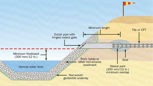
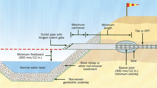
End pipes are either flush mounted (Figure 1) or cantilever style (Figure 2), depending upon the erosion control protection and susceptibility to ice damage in the receiving ditch. Flush-mounted end pipes are less susceptible to damage from ice and floating debris than cantilever-style end pipes.
Accessible description for Figure 1
Accessible description for Figure 2
End pipes are joined to the drain pipe by sleeve joints or butt joints with a minimum length of 3 m (10 ft) depending on the diameter of the drain pipe. Table 1 provides the minimum end-pipe diameter, minimum length of end pipe and maximum cantilever for both types of joints and outfall styles.
| Nominal drain pipe diameter mm (in.) | Minimum butt joint diameter mm (in.) | Minimum sleeve joint diameter mm (in.) | Minimum length mm (ft) | Maximum cantilever mm (in.) |
|---|---|---|---|---|
| 100 (4) | 100 (4) | Maximum outside diameter of drain pipe + 50 (2) | 3,000 (10) | 400 (16) |
| 150 (6) | 150 (6) | Maximum outside diameter of drain pipe + 50 (2) | 3,000 (10) | 600 (24) |
| 200 (8) | 200 (8) | Maximum outside diameter of drain pipe + 50 (2) | 3,000 (10) | 600 (24) |
| 250 (10) | 250 (10) | Maximum outside diameter of drain pipe + 50 (2) | 3,600 (12) | 600 (24) |
| 300 (12) | 300 (12) | Maximum outside diameter of drain pipe + 50 (2) | 3,600 (12) | 800 (32) |
| 350 (14) | 350 (14) | Maximum outside diameter of drain pipe + 50 (2) | 4,800 (16) | 800 (32) |
| 400 (16) | 400 (16) | Maximum outside diameter of drain pipe + 50 (2) | 5,400 (18) | 800 (32) |
| 450 (18) | 450 (18) | Maximum outside diameter of drain pipe + 50 (2) | 6,000 (20) | 1,000 (40) |
For sleeve-style joints, insert the drain pipe into the end pipe at least 300 mm (12 in.). The inside diameter of the end pipe should not exceed the outside diameter of the drain pipe by more than 50 mm (2 in.). If the inside diameter of the end pipe is less than 25 mm (1 in.) larger than the outside diameter of the drain pipe, no wrapping is required. Otherwise, wrap the joint.
For butt joints, the inside diameter of the end pipe must be equal to or larger than the inside diameter of the drain pipe but not exceed the outside diameter of the drain pipe by more than 25 mm (1 in.). Wrap the joint with a filter material or seal to ensure that soil does not enter the joint.
In coarse soil conditions, an anti seep collar may be required to eliminate the possibility of water seepage around the external diameter of the outlet pipe. The water seepage can destabilize the soils, ultimately causing a failure of the drainage outlet.
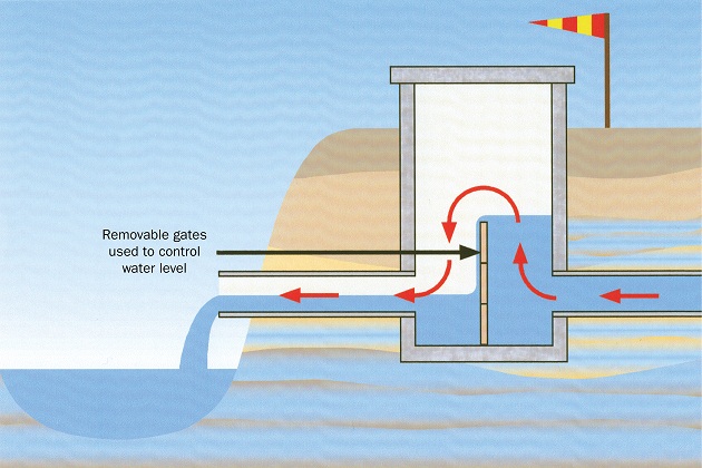
Where it is necessary to check or control the drain flow or inspect mains or other drains, install a junction box. Construct a junction box using concrete, steel or plastic, or purchase one from drainage material manufacturers. A specialized junction box called a water control device (Figure 3) can also be installed to control or completely stop the flow in the drain from getting to the outlet. This is particularly valuable if the water in the drain becomes contaminated from a spill caused by pesticide or manure application. Place junction boxes far enough upstream of the receiving water body to allow for proper design of the outfall.
Accessible description for Figure 3
Angle the end pipe downstream into the receiving ditch or drain so as not to impede normal flow, and discharge with the outside bottom of the pipe at least 0.3 m (1 ft) above normal water level or ditch bottom.
Install the outfall pipe immediately after digging the trench. Backfill and compact the trench in 75-mm (3-in.) layers to the same density of the surrounding soil for a distance of 5 m (16 ft) from the outfall. Seed the backfilled ditch/stream bank immediately. A recommended seeding mixture is creeping red fescue at 20 kg/ha (18 lb/acre) and bird's-foot trefoil at 12 kg/ha (11 lb/acre).
A hinged grate or rodent guard on the outfall pipe is essential. Install the guard immediately following the installation of the pipe. The grate can be hinged or removable to allow for cleaning and have openings with a maximum width of 25 mm (1 in.). Several different styles are available from material suppliers.
When it is necessary to construct a drainage system outfall in a very high ditch bank, prevent erosion using either of the following methods:
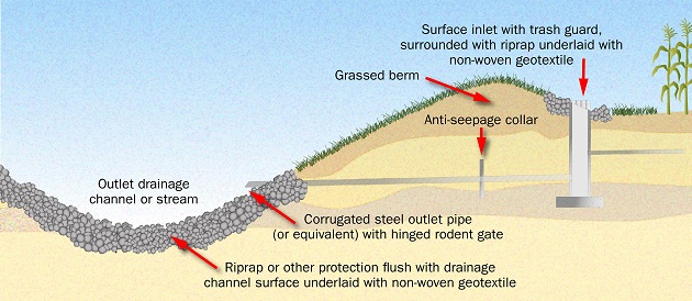
- Install a properly designed drop pipe structure to move the water down to the lower elevation. These structures are sized large enough to serve as a junction box for several main lines. The drop pipe structure, with an optional surface water inlet, is shown in Figure 4. Avoid using a surface water inlet if the tile drain has winter flow (such as springs), since this can cause blockage through ice build-up. Secure a trash guard or inlet grate on the surface inlet.
- Install a sloped, non-perforated drain pipe and end pipe.
Accessible description for Figure 4
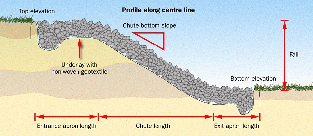
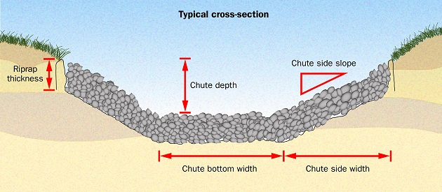
There should be no surface flow over the ditch bank at the drain system outfall location. Where it is necessary to allow surface water to enter a ditch, construct a properly designed drop structure as shown in Figure 4, or a rock chute spillway as shown in Figures 5 and 6.
Accessible description for Figure 5
Accessible description for Figure 6
For further assistance with the design and installation of a drop pipe outlet or rock chute spillway, get advice from a certified soil erosion control contractor. They are trained in the use of Ministry of Agriculture, Food and Agribusiness (OMAFA) Publication 832: Agricultural Erosion Control Structures: A Design and Construction Manual, and its associated design software.
Use a durable, permanent marker that is highly visible above crops and tall grasses to mark the location of all drainage system outfalls. If possible, note the GPS coordinates, using a handheld GPS device, so you can locate the outfall in the future. This will be especially useful once the receiving ditch and channel have matured and the outfall is difficult to see from the edge of the field.
Inspection and maintenance
A drainage system outfall must be kept clean and in good condition or the drainage system cannot function properly. Carry out an inspection in spring, fall and after severe storms to check for silting, debris, erosion, settlement and misalignment. Correct all problems immediately. Further information on the maintenance of a drainage system outfall is found in the OMAFA fact sheet, Maintenance of a subsurface drainage system.
Remember that all construction and maintenance projects must comply with existing provincial and federal legislation where applicable, for example, Drainage Act, 1990, Conservation Authorities Act, 1990, Lakes and Rivers Improvement Act, 1990, Fisheries Act, 1985 and their associated regulations.
Contact the local municipality if the outfall discharges to a municipal drain – never complete any work on a municipal drain. Contact the local conservation authority or Ministry of Natural Resources office if the outfall discharges to a natural watercourse. In all cases, obtain all the necessary approvals prior to starting any work.
Resources
Qualified tile drainage and erosion control contractors are available for the design and construction of drainage system outfalls.
For more technical information on planning, design, construction and maintaining a drainage system, refer to OMAFA Publication 29: Drainage Guide for Ontario.
Author credit
This fact sheet was written by Tim Brook, P. Eng., drainage program coordinator, OMAFA and reviewed by Sid Vander Veen, P. Eng., OMAFA, (retired).
Accessible image descriptions
Figure 1. Flush-mounted outfall.
The diagram provides detailed information such as minimum diameter or minimum length to be used with Table 1 for the design of a flush-mounted end pipe.
Figure 2. Cantilever-style outfall.
The diagram provides detailed information such as minimum diameter, minimum length, maximum cantilever to be used with Table 1 for the design of a cantilever style end pipe.
Figure 3. Water-control device.
The diagram shows how the water level in a drainage system can be controlled or stopped by means of removable gates installed in a water control device. The water level on the right side of the water control device is higher than the other side due to the heigh of the installed gates. The water is overflowing the gate and discharging to a receiving drainage channel.
Figure 4. Drop pipe outlet structure for subsurface drainage system with optional surface inlet.
The diagram shows a side view of a grassed berm that collects surface water from a field and directs it into the drop pipe outlet structure. It also shows a pipe with an anti-seepage collar connecting the structure to the drainage channel. The channel also has riprap underlaid with non-woven geotextile on the bottom of the channel.
Figure 5. Rock chute spillway (profile).
The diagram shows the side profile of a rock chute that carries water from the field at a higher elevation to a field at a lower elevation. The diagram shows the slope, fall, chute length and other sections of the chute.
Figure 6. Rock chute spillway (cross-section).
The diagram shows the cross section of a rock chute including the chute depth, side slope, chute bottom and side widths and riprap thickness.