We've moved this content over from an older government website. We'll align this page with the ontario.ca style guide in future updates.
Appendix B: Electrical safety
In addition to Guideline #12 Electrical Safety, please also consult Electrical Safety Authority (ESA) Spec 003 entitled: Electrical Guidelines for Entertainment Industry, as well as a current copy of the Ontario Electrical Safety Code, plus the safety requirements in the OHSA and its regulations.
Definitions
The definitions which have not been taken from the Ontario Electrical Safety Code or ESA are provided for convenience only and should not be interpreted to have legal significance.
- 1.1 Apple Box:
- A non-conducting rectangular structure used to support electrical equipment, lighting stands, and other production equipment. Used as a building block to accommodate varying elevations on the set. Commonly made of varnished plywood. Typical dimensions are 18"× 12" and:
- Full: 9.0" high
- Half: 4.5" high
- Third: 3.0" high
- Quarter: 2.25" high
- 1.2 Ballast:
- A resistor, transformer or electronic circuit used to limit the current to a discharge type of light source. Typically used with fluorescent tubes, HID, HMI, fixtures, etc.
- 1.3 Best Boy:
- Technician in charge of designing, setting up, supervising and taking down, a temporary power distribution system for film or video production. May supervise a crew on larger productions. Reports to Gaffer or Lighting Director.
- 1.4 Cam-Lok™:
- A standard series of single pin electrical connectors (Ball Nose) commonly used with single conductor cable for temporary power distribution system. Other configurations of this connector not compatible and not commonly used are "J", and "Posi-Lok". Refer to Table 2 for standard connector configurations.
- 1.5 CSA:
- The Canadian Standards Association sets standards for safe construction of electrical equipment. It also inspects and identifies equipment that meets the standards. Electrical equipment connected to the electrical utility distribution network must, according to the Canadian Electrical Code, be approved by CSA or Electrical Safety Authority (ESA). CSA or ESA labels affixed to electrical equipment confirm to the user the compliance with local regulations.
- 1.6 Canadian Electrical Code:
- Canadian Electrical Code: The standard for temporary or permanent electrical installations in Ontario is CSA C22.1 Part 1. The local electrical utility has the right to enter any premises which use electrical power supplied by that utility, and to shut down any equipment or systems which do not comply with the Code, and which present a hazard to the public.
- 1.7 Competent:
- One qualified by knowledge, training and experience to perform assigned work, and has knowledge of any potential or actual danger to health and safety in the workplace. See also definitions of competent person in section 1 of OHSA and competent worker in section 1 of O. Reg. 213/01.
- 1.8 Electrical Distribution Box:
- A device which permits the branching of power to two or more loads or additional distribution boxes. Usually consists of breakers or fuses feeding 120V, single phase, female connectors (line, neutral and ground). Per Table 1.
- 1.9 Electrician:
- Certified under the Trades Qualifications and Apprenticeship Act to do electrical work, or a person with equivalent qualifications by training and experience. (Refer to section 1.16 below)
- 1.10 Gaffer/Lighting Director:
- The head of the lighting department for a film or video production. May design lighting positions, establish choice of fixtures and accessories. Reports to the Director of Photography for film or Technical Director for video. (Refer to section 1.16 below).
- 1.11 Generator Operator:
- Technician in charge of setting up, starting, monitoring, balancing the load, and shutting down an electrical generator.
- 1.12 Grip:
- A technician who places and adjusts accessories which alter the quality and quantity of light. The Grip also assembles dolly track, scaffold, legs, etc. , and handles the camera dolly during shoots. Supervisor or department head of a number of Grips is referred to as the “Key Grip”.
- 1.13 Ground:
- A metal plate, rod, water pipe or other conductor buried or driven into the earth and providing an uninterrupted electrical path to earth.
- 1.14 Head:
- The light emitting section of a luminarie.
- 1.15 Joy™:
- A trade name that has become generic. A brand of electrical connector employing low profile rubber moulded insulation and cylindrical pins, commonly used on a production set or in TV studios. The connector construction permits hard duty usage
- 1.16 Lighting Technician:
- Sets up and takes down power distribution systems (excluding tie-ins), lighting fixtures, etc., under the direct supervision of the Gaffer, Lighting Director or Technical Director on a video or film production set.
- 1.17 Luminaire:
- A lighting fixture consisting of a light source, socket, electrical wiring and connector, enclosure, and optionally, switch, reflectors(s), lens(es), ballast, supporting devices, and additional apparatus for altering the quality, colour, and quantity of light emitted by the apparatus. Typical styles include Borderlight, Brute, Carbon Arc, Cyc (Laramie) Strip, Ellipsoidal Spotlight, Followspot, Fresnel, HMI, Inky, Par(can), Scoop, Soft (light), Space Light, Strip Light, Sungun, Tenner, Tweenie, etc.
General rules
2.1 All electrical personnel shall have a basic understanding of electrical theory and power distribution.
2.2 Load connectors in Electric Distribution Boxes (Table 1) and Adaptors (Table 2) shall comply with section 14-100 of the Canadian Electrical Code Part 1.
2.3 The power supply to electrical installations, equipment or conductors shall be disconnected, locked out of service and tagged before any work is done, and while it is being done on or near live exposed parts of the installations, equipment or conductors (as per section 42(1) of Reg. 851).
2.4 When there is a hazard from electrical contact in wet locations, a ground fault circuit interrupter shall be installed at the receptacle or on the circuit at the panel (as per section 44.1 of Reg. 851 and section 190(4) of O. Reg. 213/91).
2.5 Consult the Ontario Hydro and EUSA Handbooks/Codes for technical support.
2.6 Care should be taken not to walk on or drive over electrical cables.
Power sources
3.0.2. Voltages and power distribution systems that may be encountered in Canada:- 120/240: 1 phase 3 wire
- 120/208: 3 phase 4 wire "Y"
- 120/208: 3 phase 3 wire "D"
- 277/480: Phase to ground/phase to phase on 480 volt 3 phase system"
- 347/600: Phase to ground/phase to phase on 600 volt 3 phase system"
3.0.4. An Electrician should tie-in to all electrical distribution systems of 300 volts and higher.
3.1 Diesel Generator Sources
3.1.1. Generators shall be grounded as required by Rule 10 – 106 of the Ontario Electrical Safety Code (OESC).
3.1.2. Generators should have an emergency stop system.
3.1.3. All generators shall be operated and maintained by a properly trained operator as required by section 25(2)(a) of OHSA .
3.1.4. Ground Fault Indicators, if required by Rule 10 -106(2) of the OESC , should be readily visible to the operator or supplied with a suitable alarm.
3.1.5. Generators should only be started under no load conditions, and unless under an emergency condition, stopped under a no load condition.
3.1.6. The operator or competent assistant should supervise the generator at all times while it is running, and should be available to activate the emergency stop system.
3.2 Utility Sources
3.2.1. Ontario Electrical Safety Code requires a wiring permit to be taken out when a temporary wiring distribution system is to be set up. Section 44.100.
3.2.2. The Gaffer should analyse the existing loads on a distribution panel and determine the excess capacity that may be used for the temporary load, before connecting a temporary power distribution system to the panel.
3.2.3. The Gaffer should notify other users of power from the same panel that their loads may be disconnected if the main breaker feeding the panel is tripped under overload conditions (i.e. , for such permanent loads as interior building lights, exit lights, emergency lighting, computers, phone system and elevators). The Gaffer should determine which loads will potentially create a safety hazard if shut down and should take suitable precautionary actions.
3.2.4. Temporary leads exiting a distribution panel should be secured such that the weight of any cables does not put a strain on any electrical connector.
3.2.5. Temporary leads which cannot be passed through CSA approved cable clamps in the side of the distribution panel and which must pass through the front opening of the panel in such a manner that the covers cannot be replaced, should be clearly marked identifying the electrical hazard and the name of the person responsible for the installation. If the panel is in an electrical room, all doors opening directly into the room shall be posted with the above warning (as per section 41 of Reg. 851).
3.2.6. Where 2 or more distribution panels are used to feed the temporary distribution systems, the systems should be kept physically separate from each other. Under no condition should two (2) or more distribution panels be used to feed a single temporary distribution system (i.e., one with a single main trunk).
Temporary power distribution
4.1. Tying-in shall not be performed in the rain, since the protection provided by insulated PPE required by Rule 2 - 306 of OESC will be negated by the rain.
4.2. Appropriate proper non-conducting protective equipment such as rubber-soled shoes, rubber gloves, and mats shall be worn / used when tying-in (as per Rule 2 306 of OESC).
4.3. A separate ground that is not returned to neutral should be part of any electrical distribution system.
4.4. Connectors and cable shall be provided with standard colour coding:
- Red, Blue, Black: line
- White: neutral
- Green: ground
Where single conductor cables are used, the colour codes should be applied with coloured tape to both ends of each cable before the cables are connected. Care shall be taken to ensure that any `length' colour coding is not confused with the above coding
4.5. All electrical personnel shall be aware of the load bearing capacity of each type of cable, adaptor, or distribution box in use on the set. Refer to Tables 1, 2 and 3.
4.6. All power feeds should be protected from mechanical damage. In high traffic areas, cables shall be laid in troughs or shall be covered.
4.7. All Electrical Distribution Boxes as shown in Table 1 shall be labelled as to the rated voltage and current.
4.8. Any “T-off” or other connection that is not being used should be sealed or capped to prevent accidental electrical contact.
4.9. A fused or breakered disconnect box of suitable amperage should be used between the power source and the “on set” distribution when tying-in.
4.10. All distribution boxes and cable connections should be kept clear of water or damp surfaces by use of non-conducting material.
4.11. If it is not practical to disconnect electrical equipment or conductors from the power supply (i.e. , to an energized “T-off”), procedures shall be in use for building a temporary electrical distribution system, which includes the following sequence:
- load switched – off
- connect the ground
- connect the neutral
- connect the lines
- energize the load
When dismantling a temporary electrical distribution system, the reverse sequence of above procedures shall be in use.
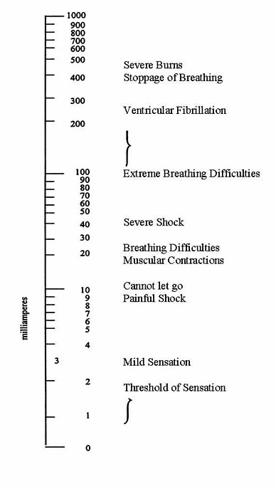
4.12. When work is being performed on any live electrical system, a competent person who is able to recognize the hazards in the work being performed shall be present. A second worker must be properly equipped and trained in all requirements to perform a rescue, including First Aid and CPR. Please refer to Table 4 for information on physiological effects of electric currents.Lighting
5.1. Lighting equipment connected to a utility power source shall have CSA approval, C22.2 No. 166 or ESA approval (as per section 40 of Reg. 851).5.2. Scaffolds or other metal grids used to support lighting or power distribution should be grounded.
5.3. All personnel shall be made aware of high voltages used by gas discharge lamps such as neons, HMIs, CSIs and fluorescents (as per 2.5(2)(a) of (OHSA). Anyone using these sources should be familiar with the ballasts used and ensure that any safety devices are in proper working order.
5.4. Any open-faced unit shall have protection against the shrapnel effect caused by an exploding bulb, particularly when in proximity to people.Safety wire or chain should be used in proximity to people.
5.5. In the event of a power or lighting system failure, emergency lighting should be provided to illuminate a safe means of egress.
Carrying and handling
6.1. When carrying or handling equipment, protective footwear should be worn at all times. CSA Z-195 Standard, Protective Footwear Grade 1 type is recommended (as per section 23 of O. Reg. 213/91).
6.2. In addition to protective footwear, protective equipment including gloves, protective glasses, etc. , shall be worn when carrying, handling or moving hot luminaries. Bulbs should be allowed to cool sufficiently before the luminaries are moved.
6.3. Correct procedures should be exercised when performing lifting, lowering, carrying, pushing and pulling tasks.
Tasks involving lifting, lowering, pushing, pulling and carrying are difficult to analyse. Concerns may arise if the object handled is bulky or asymmetric, and/or if awkward postures are used when performing these tasks. If a concern exists when handling a load greater than 18 lbs. in weight, a Ministry of Labour, Training and Skills Development ergonomist may be contacted. A list of all MLTSD regional offices can be found on the website.
The following are some factors affecting maximum acceptable weight of lifting, lowering and carrying, and forces of push and pull:
- vertical distance from floor
- distance of lift/lower/carry/push/pull
- frequency of activity
- percentage of industry population capable of performing the task
- width of object away from body
- physical dimensions of the person performing task
6.1. Refer to Guideline No. 22 (Mobile Elevating Equipment), and Guideline No. 23 (Scaffolding) for scaffold work protection while erecting, dismantling, ascending and working on same.
Operations
7.1. The Gaffer should maintain a log book of major equipment repairs performed “on set”.7.2. Any equipment, cable or box that has been repaired “on set” shall be carefully tested for continuity and polarity before being re-used. Rental equipment that has been repaired on set should have the details of the repair noted on the equipment so that the rental company can verify that the repair has been properly completed.
7.3. All lighting fixtures and/or stands shall be adequately supported and weighted, etc., to prevent tipping.
7.4. In the event of rain or high humidity, all Human Machine Interfaces (HMIs) or similar units shall be covered to prevent rain from entering the unit and ballast (as required by Rule 2 – 400 of OESC).
7.4. The ballast and head must be grounded.
7.5. Prior to “striking” an HMI or similar source, the operators shall make sure that no one is in contact with the unit, any support, or the ballast.
7.5.1. In damp or rainy conditions make sure that any other persons are clear of the lamp head, as humid conditions increase the conductivity of the air, and thus the likelihood of arcing.
7.5.2. All personnel on a set shall be advised that various “arc” type lamps including HMIs emit much larger amounts of ultra-violet (UV) light than tungsten lamps. Care should be taken to protect against skin and eye damage when they are set up close to people.
7.6. Before a lighting fixture is relamped, repaired or otherwise worked on, the fixture shall be switched off and disconnected from the power source.
Miscellaneous
8.1. Lasers shall be operated by a competent technician.
8.1.1. Eye damage will result from looking directly into a laser source.
8.1.2. No one should ever look directly into a laser source.
8.1.3. Consult a laser technician for additional possible hazards.
Fall protection for scaffold erection and dismantling
- Positive fall protection must be used when a worker is at risk of falling a distance of at least 3metres. Generally, positive fall protection could include the following: a guardrail, a fall arrest system, a travel restraint system, a specially equipped ladder. See also Guideline No. 21 : Working at Heights.
- A fall arrest system consisting of a full body harness, safety belt, lanyard and large locking snap hook, may be used by workers engaged in erecting or dismantling a scaffold.
- When lifting materials more than 3 frames in height from ground level, a well wheel and devit should be used. The worker stationed on the scaffold platform receiving the material must be equipped with a fall arrest system. Where practicable a lifeline connected to a fixed structure or building and/or horizontal or vertical static line should be used.
| Box # | Phases | Breakers | Line Connector | Load Connector | Maximum Output Load Per Connector |
|---|---|---|---|---|---|
| 1 | 3-Phase | 350 Amp. 3 Pole |
Cam Lok | Cam Lok | 315 Amps |
| 2 | Single | N/A | Camlok | Pyle National | N/A |
| 3 | 3-Phase | N/A | Camlok | Pyle National | N/A |
| 4 | Single | 60 × 60 Amp | Camlok | 6 × 45A Joy | 5 KW |
| 4A | 3-Phase | 60 × 60 Amp | Camlok | 6 × 45A Joy | 5 KW |
| 5 | Single | 2 × 60 Amp 2 Pole |
Camlok | 2 × 4 Pin 60 Amp Joy |
N/A |
| 5A | 3-Phase | 3 × 60 Amp 2 Pole |
Camlok (1 × 5 wire) |
3 × 4 Pin 60 Amp Joy |
N/A |
| 6 | Single | 6 × 20 | 4 Pin Joy | 6 × 20 Amp Joy | 2 KFW |
| 6A | Single | 6 × 20 | 4 Pin Joy | 6 × Duplex "U" 15 Amp |
2 KFW |
| 6 Special |
Single | 2 × 40 Amp 4 × 20 Amp |
4 Pin Joy | 2 × 45A Joy 4 × 20A Joy |
5 KW or 2 KW |
| 7 | Single | 2 × 60 | 4 Pin Joy | 2 × 45 Amp Joy | 5 KW |
| 8 | Single | 3 × 20 | 5K Joy | 3 × 20 Amp Joy | 2 KW |
| 8A | Single | 3 × 20 | 5K Joy | 3 × Duplex "U" 15 Amp |
2 KW |
| 9 | N/A | N/A | N/A | N/A | N/A |
| 10 | 3-Phase | 3 × 100 Amp | Cam Lok | Cam Lok | 10 KW |
Single refers to 1 phase 3 Wire - See table in 3. of this appendix
| Phases | Name | Breakers | Line Connector | Load Connector | Maximum Output Load Per Connector |
|---|---|---|---|---|---|
| N/A | 20 Amp 4-way |
– | 20 Amp Joy | 2 × Duplex U 15 Amp |
2 KW |
| N/A | 50 Amp 4 Way |
4 × 20 | 45 Amp Joy | 2 × Duplex U | 2 KW |
| 3 Phase | 200 Amp Fused Disconnect |
3 × 200 Amp | Cam Lok (1 × 5 Wire) |
Cam Lok 2 (1 × 5 Wire) |
160 Amp |
| 3 Phase | 400 Amp Fused Disconnect |
3 × 400 Amp | Cam Lok (1 × 5 Wire) |
Cam Lok | 320 Amp |
| N/A | 8-Way | 4 × 20 Amp | 45 Amp Joy | 4 × Duplex U 15 Amp |
2 KW |
| Cable Size | Nominal Amperes |
|---|---|
| 4 ⁄ 0 | 315 ⁄ phase |
| 3 ⁄ 0 | 230 ⁄ phase |
| 2 ⁄ 0 | 175 ⁄ phase |
| 2 | 115 ⁄ phase |
| 6 ⁄4 Joy | 60 ⁄ Phase |
| 6 ⁄3 5K Joy | 45 ⁄ Phase |
| 10 ⁄3 Twist Lock | 30 |
| 12 ⁄3 S⁄SO⁄SJ | 20 |
| 14 ⁄3 SJ | 15 |
| 16 ⁄3 SJ | 10 |
The rating of a cable may be less than that shown in the above Table if cables are bundled tightly together, are covered with mats or set pieces, if the insulation has deteriorated, and in high ambient heat conditions.
Physiological effects of electric currents
Table 4
References: