

Part 4 — Structural Design
Section 4.1. Structural Loads and Procedures
4.1.1. General
4.1.1.1. Scope
- The scope of this Part shall be as described in Subsection 1.3.3. of Division A.
4.1.1.2. Definitions
- Words that appear in italics in this Part are defined in Article 1.4.1.2. of Division A.
4.1.1.3. Design Requirements
- Buildings and their structural members and connections, including formwork and falsework, shall be designed to have sufficient structural capacity and structural integrity to safely and effectively resist all loads, effects of loads and influences that may reasonably be expected, having regard to the expected service life of buildings, and shall in any case satisfy the requirements of this Section. (See Note A-4.1.1.3.(1))
- Buildings and their structural members shall be designed for serviceability, in accordance with Articles 4.1.3.4., 4.1.3.5. and 4.1.3.6. (See Note A-4.1.1.3.(2))
- All permanent and temporary structural members, including the formwork and falsework of a building, shall be protected against loads exceeding the specified loads during the construction period except when, as verified by analysis or test, temporary overloading of a structural member would result in no impairment of that member or any other member.
- Reserved.
- Precautions shall be taken during all phases of construction to ensure that the building is not damaged or distorted due to loads applied during construction.
4.1.1.4. Reserved
4.1.1.5. Design Basis
- Except as provided in Sentence (2), buildings and their structural members shall be designed in conformance with the procedures and practices provided in this Part.
- Provided the design is carried out by a person especially qualified in the specific methods applied and provided the design demonstrates a level of safety and performance in accordance with the requirements of this Part, buildings and their structural components falling within the scope of this Part that are not amenable to analysis using a generally established theory may be designed by,
- evaluation of a full-scale structure or a prototype by a loading test, or
- studies of model analogues.
(See Note A-4.1.1.5.(2))
4.1.2. Specified Loads and Effects
4.1.2.1. Loads and Effects (See Note A-4.1.2.1.)
- Except as provided in Article 4.1.2.2., the following categories of loads, specified loads and effects shall be taken into consideration in the design of a building and its structural members and connections:
| Symbol | Description |
|---|---|
| D | dead load — a permanent load due to the weight of building components, as specified in Subsection 4.1.4. |
| E | earthquake load and effects — a rare load due to an earthquake, as specified in Subsection 4.1.8. |
| H | a permanent load due to lateral earth pressure, including groundwater |
| L | live load — a variable load due to intended use and occupancy (including loads due to cranes and the pressure of liquids in containers), as specified in Subsection 4.1.5. |
| LXC | live load exclusive of crane loads, |
| C | live load due to cranes including self weight, |
| Cd | self weight of all cranes positioned for maximum effects, |
| C7 | crane bumper impact load, |
| P | permanent effects caused by pre-stress, |
| S | variable load due to snow, including ice and associated rain, as specified in Article 4.1.6.2., or due to rain, as specified in Article 4.1.6.4. |
| T | effects due to contraction, expansion, or deflection caused by temperature changes, shrinkage, moisture changes, creep, ground settlement, or a combination thereof, and (See Note A-4.1.2.1.(1)) |
| W | wind load — a variable load due to wind, as specified in Subsection 4.1.7. |
where
- load means the imposed deformations (i.e. deflections, displacements or motions that induce deformations and forces in the structure), forces and pressures applied to the building structure,
- permanent load is a load that changes very little once it has been applied to the structure, except during repair,
- variable load is a load that frequently changes in magnitude, direction or location, and
- rare load is a load that occurs infrequently and for a short time only.
- Minimum specified values of the loads described in Sentence (1), as set forth in Subsections 4.1.4. to 4.1.8., shall be increased to account for dynamic effects where applicable.
- For the purpose of determining specified loads S, W or E in Subsections 4.1.6., 4.1.7. and 4.1.8., buildings shall be assigned an Importance Category based on intended use and occupancy, in accordance with Table 4.1.2.1. (See Note A-4.1.2.1.(3))
Table 4.1.2.1. Importance Categories for Buildings
Forming Part of Sentence 4.1.2.1.(3)
| Type of Building | Importance Category |
|---|---|
| A Low Importance Category building is a building that represents a low direct or indirect hazard to human life in the event of structural failure. | Low |
| A Normal Importance Category building is a building that does not meet the criteria for a Low Importance Category building, High Importance Category building or post-disaster building. | Normal |
| A High Importance Category building is a building that provides a greater degree of safety to human life than a Normal Importance Category building. Community centres and elementary, middle and secondary schools are High Importance Category buildings. | High |
| A post-disaster building. | Post-disaster |
Notes to Table 4.1.2.1.
4.1.2.2. Loads Not Listed
- Where a building or structural member can be expected to be subjected to loads, forces or other effects not listed in Article 4.1.2.1., such effects shall be taken into account in the design based on the most appropriate information available. (See Note A-4.1.2.2.(1))
4.1.3. Limit States Design (See Note A-4.1.3.)
4.1.3.1. Definitions
- In this Subsection, the term,
- "limit states" means those conditions of a building structure that result in the building ceasing to fulfill the function for which it was designed. (Those limit states concerning safety are called ultimate limit states (ULS) and include exceeding the load-carrying capacity, overturning, sliding and fracture; those limit states that restrict the intended use and occupancy of the building are called serviceability limit states (SLS) and include deflection, vibration, permanent deformation and local structural damage such as cracking; and those limit states that represent failure under repeated loading are called fatigue limit states),
- "specified loads" (C, D, E, H, L, P, S, T and W) means those loads defined in Article 4.1.2.1.,
- "principal load" means the specified variable load or rare load that dominates in a given load combination,
- "companion load" means a specified variable load that accompanies the principal load in a given load combination,
- "service load" means a specified load used for the evaluation of a serviceability limit state,
- "principal-load factor" means a factor applied to the principal load in a load combination to account for the variability of the load and load pattern and the analysis of its effects,
- "companion-load factor" means a factor that, when applied to a companion load in the load combination, gives the probable magnitude of a companion load acting simultaneously with the factored principal load,
- "importance factor, I," means a factor applied in Subsections 4.1.6., 4.1.7. and 4.1.8. to obtain the specified load and take into account the consequences of failure as related to the limit state and the use and occupancy of the building,
- "factored load" means the product of a specified load and its principal-load factor or companion-load factor,
- "effects" refers to forces, moments, deformations or vibrations that occur in the structure,
- "nominal resistance, R," of a member, connection or structure, is based on the geometry and on the specified properties of the structural materials,
- "resistance factor, φ," means a factor applied to a specified material property or to the resistance of a member, connection or structure, and that, for the limit state under consideration, takes into account the variability of dimensions and material properties, workmanship, type of failure and uncertainty in the prediction of resistance, and
- "factored resistance, ," means the product of nominal resistance and the applicable resistance factor.
4.1.3.2. Strength and Stability
- A building and its structural components shall be designed to have sufficient strength and stability so that the factored resistance, , is greater than or equal to the effect of factored loads, which shall be determined in accordance with Sentence (2).
- Except as provided in Sentence (3), the effect of factored loads for a building or structural component shall be determined in accordance with the requirements of this Article and the following load combination cases, the applicable combination being that which results in the most critical effect:
- for load cases without crane loads, the load combinations listed in Table 4.1.3.2.-A, and
- for load cases with crane loads, the load combinations listed in Table 4.1.3.2.-B. (See Note A-4.1.3.2.(2))
- Other load combinations that must also be considered are the principal loads acting with the companion loads taken as zero.
- Where the effects due to lateral earth pressure, H, restraint effects from pre-stress, P, and imposed deformation, T, affect the structural safety, they shall be taken into account in the calculations, with load factors of 1.5, 1.0 and 1.25 assigned to H, P and T respectively. (See Note A-4.1.3.2.(4))
- Except as provided in Sentence 4.1.8.16.(2), the counteracting factored dead load—0.9D in load combination cases 2, 3 and 4 and 1.0D in load combination case 5 in Table 4.1.3.2.-A, and 0.9D in load combination cases 1 to 5 and 1.0D in load combination case 6 in Table 4.1.3.2.-B—shall be used when the dead load acts to resist overturning, uplift, sliding, failure due to stress reversal, and to determine anchorage requirements and the factored resistance of members. (See Note A-4.1.3.2.(5))
- The principal-load factor 1.5 for live loads L in Table 4.1.3.2.-A and in Table 4.1.3.2.-B may be reduced to 1.25 for liquids in tanks.
Table 4.1.3.2.-A — Load Combinations Without Crane Loads for Ultimate Limit States
Forming Part of Sentences 4.1.3.2.(2), (5) to (10) and 4.2.4.1.(3)
| Case | Load Combination[1] — Principal Loads | Load Combination[1] — Companion Loads |
|---|---|---|
| 1 | 1.4D[2] | N/A |
| 2 | (1.25D[3] or 0.9D[4]) + 1.5 L[5] | 1.0 S[6] or 0.4 W |
| 3 | (1.25D[3] or 0.9D[4]) + 1.5 S | 1.0 L[6][7] or 0.4 W |
| 4 | (1.25D[3] or 0.9D[4]) + 1.4 W | 0.5 L[7] or 0.5 S |
| 5 | 1.0D[4] + 1.0E[8] | 0.5 L[6][7] + 0.25 S[6] |
Notes to Table 4.1.3.2.-A:
- See Sentences 4.1.3.2.(2) to (4).
- See Sentence 4.1.3.2.(9).
- See Sentence 4.1.3.2.(8).
- See Sentence 4.1.3.2.(5).
- See Sentence 4.1.3.2.(6).
- See Article 4.1.5.5.
- See Sentence 4.1.3.2.(7).
- See Sentence 4.1.3.2.(10).
Table 4.1.3.2.-B — Load Combinations With Crane Loads for Ultimate Limit States
Forming Part of Sentences 4.1.3.2.(2), (5) to (8) and (10)
| Case | Load Combination[1] — Principal Loads | Load Combination[1] — Companion Loads |
|---|---|---|
| 1 | (1.25D[2] or 0.9D[3]) + (1.5C + 1.0Lxc) | 1.0 S[4] or 0.4 W |
| 2 | (1.25D[2] or 0.9D[3]) + (1.0C + 1.5Lxc[5]) | 1.0 S[4] or 0.4 W |
| 3 | (1.25D[2] or 0.9D[3]) + 1.5 S | 1.0C + 1.0Lxc[4][6] |
| 4 | (1.25D[2] or 0.9D[3]) + 1.4 W | 1.0C7 + 0.5Lxc[4][6] |
| 5 | (1.25D[2] or 0.9D[3]) + C7 | N/A |
| 6 | 1.0D[3] + 1.0E[8] | 1.0Cd + 0.5Lxc[4][6] + 0.25 S[4] |
Notes to Table 4.1.3.2.-B:
- See Sentences 4.1.3.2.(2) to (4).
- See Sentence 4.1.3.2.(8).
- See Sentence 4.1.3.2.(5).
- See Article 4.1.5.5.
- See Sentence 4.1.3.2.(6).
- See Sentence 4.1.3.2.(7).
- Side thrust due to cranes need not be combined with full wind load.
- See Sentence 4.1.3.2.(10).
- The companion-load factor for live loads L in Table 4.1.3.2.-A and in Table 4.1.3.2.-B shall be increased by 0.5 for storage areas and equipment areas and service rooms referred to in Table 4.1.5.3.
- Except as provided in Sentence (9), the load factor 1.25 for dead load, D, for soil, superimposed earth, plants and trees given in Tables 4.1.3.2.-A and 4.1.3.2.-B shall be increased to 1.5, except that when the soil depth exceeds 1.2 m, the factor may be reduced to but not less than 1.25, where is the depth of soil, in m, supported by the structure.
- A principal-load factor of 1.5 shall be applied to the weight of saturated soil used in load combination case 1 of Table 4.1.3.2.-A.
- Earthquake load, E, in load combination cases 5 of Table 4.1.3.2.-A and 6 of Table 4.1.3.2.-B includes horizontal earth pressure due to earthquake determined in accordance with Sentence 4.1.8.16.(7).
- Provision shall be made to ensure adequate stability of the structure as a whole and adequate lateral, torsional and local stability of all structural parts.
- Sway effects produced by vertical loads acting on the structure in its displaced configuration shall be taken into account in the design of buildings and their structural members.
4.1.3.3. Fatigue
- A building and its structural components, including connections, shall be checked for fatigue failure under the effect of cyclical loads, as required in the standards listed in Section 4.3. (See Note A-4.1.3.3.(1))
- Where vibration effects, such as resonance and fatigue resulting from machinery and equipment, are likely to be significant, a dynamic analysis shall be carried out. (See Note A-4.1.3.3.(2))
4.1.3.4. Serviceability
- A building and its structural components shall be checked for serviceability limit states as defined in Clause 4.1.3.1.(1)(a) under the effect of service loads for serviceability criteria specified or recommended in Articles 4.1.3.5. and 4.1.3.6. and in the standards listed in Section 4.3. (See Note A-4.1.3.4.(1))
- The effect of service loads on the serviceability limit states shall be determined in accordance with this Article and the load combinations listed in Table 4.1.3.4., the applicable combination being that which results in the most critical effect.
- Other load combinations that must also be considered are the principal loads acting with the companion loads taken as zero.
- Deflections calculated for load types P, T and H, if present, with load factors of 1.0 shall be included with the calculated deflections due to principal loads.
- The determination of the deflection shall consider the following:
- for materials that result in increased deformations over time under sustained loads, the deflection calculation shall consider the portion of live load, L, that is sustained over time, Ls, and the portion that is transitory, Lt, and
- the calculated deflection due to dead load, D, and sustained live load, Ls, shall be increased by a creep factor as specified in the standards listed in Section 4.3. to obtain the additional long-term deflection.
- The determination of the long-term settlement of foundations shall consider the following:
- for foundation soil types that result in increased settlement over time under sustained loads, the additional long-term settlements shall be determined for the portion of live load, L, that is sustained over time, Ls, and the portion that is transitory, Lt, and
- the additional long-term settlements due to dead load, , and sustained live loads, , shall be calculated from the foundation soil properties provided by a qualified professional geotechnical engineer.
Table 4.1.3.4. — Loads and Load Combinations for Serviceability
Forming Part of Sentence 4.1.3.4.(2)
| Limit State | Structural Parameter | Load Case | Load Combination — Principal Loads | Load Combination — Companion Loads |
|---|---|---|---|---|
| Deflection for materials not subject to creep | Deflection of the structure or of components of the structure[1] | 1 | 1.0D + 1.0 L | 0.3 W or 0.35 S |
| Deflection for materials not subject to creep | Deflection of the structure or of components of the structure[1] | 2 | 1.0D + 1.0 W | 0.35 L[2] or 0.35 S |
| Deflection for materials not subject to creep | Deflection of the structure or of components of the structure[1] | 3 | 1.0D + 1.0 S | 0.3 W or 0.35 L[2] |
| Deflection for materials subject to creep | Total deflection of the structure or of components of the structure[3] | 1 | 1.0D + 1.0Ls[4] + 1.0Lt[5] | 0.3 W or 0.35 S |
| Deflection for materials subject to creep | Total deflection of the structure or of components of the structure[3] | 2 | 1.0D + 1.0 W | 0.35 L[2] or 0.35 S |
| Deflection for materials subject to creep | Total deflection of the structure or of components of the structure[3] | 3 | 1.0D + 1.0 S | 0.3 W or 0.35 L[2] |
| Vibration serviceability | Acceleration | [6] | [6] | [6] |
Notes to Table 4.1.3.4.:
- The calculated deflection due to dead load, D, is permitted to be excluded where specified in the standards listed in Section 4.3.
- The companion load factor of 0.35 for live load, L, shall be increased to 0.5 for storage areas, equipment areas and service rooms.
- The calculated immediate deflection due to dead load, D, is permitted to be excluded where specified in the standards listed in Section 4.3.
- Ls = sustained portion of the live load, L.
- Lt = transitory portion of the live load, L.
- See Note A-Table 4.1.3.4.
4.1.3.5. Deflection
- In proportioning structural members to limit serviceability problems resulting from deflections, consideration shall be given to
- the intended use of the building or member,
- limiting damage to non-structural members made of materials whose physical properties are known at the time of design,
- limiting damage to the structure itself, and
- creep, shrinkage, temperature changes and prestress.
(See Note A-4.1.3.5.(1))
- The lateral deflection of buildings due to service wind and gravity loads shall be checked to ensure that structural elements and non-structural elements whose nature is known at the time the structural design is carried out, will not be damaged.
- Except as provided in Sentence (4), the total drift per storey under service wind and gravity loads shall not exceed 1/500 of the storey height unless other drift limits are specified in the design standards referenced in Section 4.3. (See Note A-4.1.3.5.(3))
- The deflection limits required in Sentence (3) do not apply to industrial buildings or sheds if experience has proven that greater movement will have no significant adverse effects on the strength and function of the building.
- The building structure shall be designed for lateral deflection due to E, in accordance with Article 4.1.8.13.
4.1.3.6. Vibration
- Floor systems susceptible to vibration shall be designed so that vibrations will have no significant adverse effects on the intended occupancy of the building. (See Note A-4.1.3.6.(1))
- Where floor vibrations caused by resonance with operating machinery or equipment are anticipated, dynamic analysis of the floor system shall be carried out. (See Note A-4.1.3.6.(2))
- Where the fundamental vibration frequency of a structural system supporting an assembly occupancy used for rhythmic activities, such as dancing, concerts, jumping exercises or gymnastics, is less than 6 Hz, the effects of resonance shall be investigated by means of a dynamic analysis. (See Note A-4.1.3.6.(3))
- A building susceptible to lateral vibration under wind load shall be designed in accordance with Article 4.1.7.1. so that the vibrations will have no significant adverse effects on the intended use and occupancy of the building. (See Note A-4.1.3.6.(4))
4.1.4. Dead Loads
4.1.4.1. Dead Loads
- The specified dead load for a structural member consists of,
- the weight of the member itself,
- the weight of all materials of construction incorporated into the building to be supported permanently by the member,
- the weight of partitions,
- the weight of permanent equipment, and
- the vertical load due to soil, superimposed earth, plants and trees.
- In areas of a building for which partitions are shown on the drawings, the weight of partitions referred to in Clause (1)(c) shall be taken as the actual weight of such partitions. (See Note A-4.1.4.1.(2))
- In areas of a building for which partitions are not shown on the drawings, the weight of partitions referred to in Clause (1)(c) shall be a partition weight allowance determined from the anticipated weight and position of the partitions, but shall not be less than 1 kPa over the area of floor being considered. (See Note A-4.1.4.1.(3))
- Partition loads used in design shall be shown on the drawings.
- Where the partition weight allowance referred to in Sentence (3) is counteractive to other loads, it shall not be included in the design calculations.
- Except for structures where the dead load of soil is part of the load-resisting system, where the dead load due to soil, superimposed earth, plants and trees is counteractive to other loads, it shall not be included in the design calculations. (See Note A-4.1.4.1.(6))
4.1.5. Live Loads Due to Use and Occupancy
4.1.5.1. Loads Due to Use of Floors and Roofs
- Except as provided in Sentence (2), the specified live load on an area of floor or roof depends on the intended use and occupancy, and shall not be less than either the uniformly distributed load patterns listed in Article 4.1.5.3., the loads due to the intended use and occupancy, or the concentrated loads listed in Article 4.1.5.9., whichever produces the most critical effect. (See Note A-4.1.5.1.(1))
- For buildings in the Low Importance Category as described in Table 4.1.2.1., a factor of 0.8 may be applied to the live load.
4.1.5.2. Uses Not Stipulated
- Except as provided in Sentence (2), where the use of an area of floor or roof is not provided for in Article 4.1.5.3., the specified live loads due to the use and occupancy of the area shall be determined from an analysis of the loads resulting from the weight of,
- the probable assembly of persons,
- the probable accumulation of equipment and furnishings, and
- the probable storage of materials.
- For buildings in the Low Importance Category as described in Table 4.1.2.1., a factor of 0.8 may be applied to the live load.
4.1.5.3. Full and Partial Loading
- The uniformly distributed live load shall be not less than the value listed in Table 4.1.5.3., which may be reduced as provided in Article 4.1.5.8., applied uniformly over the entire area or on any portions of the area, whichever produces the most critical effects in the members concerned.
Table 4.1.5.3. Specified Uniformly Distributed Live Loads on an Area of Floor or Roof
Forming Part of Sentence 4.1.5.3.(1)
| Use of Area of Floor or Roof | Minimum Specified Load, kPa |
|---|---|
| 4.8 |
| 4.8 |
| 4.8 |
| 4.8 |
| 4.8 |
| 4.8 |
| 4.8 |
| 4.8 |
| 4.8 |
| 4.8 |
| 4.8 |
| 4.8 |
| 4.8 |
| 4.8 |
| 4.8 |
| 4.8 |
| 2.4 |
| 2.9 |
| 2.9 |
| 2.9 |
| 2.4 |
| 2.4 |
| 2.4 |
| 4.8 | |
| 1.4 |
| 0.5 |
| 4.8 |
| 4.8 |
| [3] |
| 4.8 |
| [3] | |
| 2.4 | |
| 3.6[4] |
| 3.6[4] |
| 3.6[4] |
| 3.6[4] |
| 3.6[4] |
| 3.6[4] |
| 4.8 |
| 6.0[4] |
| 4.8 |
| 2.4 |
| 6.0 |
| 12.0 |
| 4.8 |
| 7.2 |
| 2.9 |
| 4.8 |
| 2.4 |
| 3.6 |
| 1.9 |
| 3.6 |
| 3.6 |
| 3.6 |
| 1.9 |
| 2.4 |
| 1.9 |
| 1.9 |
| 1.9 |
| 4.8 |
| 1.0[5] |
| 12.0[5] |
| 4.8[4] |
| 2.4 |
| [5] |
| 4.8[4] |
Notes to Table 4.1.5.3.:
- See Note A-Table 4.1.5.3.
- See Article 4.1.5.6.
- See Article 4.1.5.4.
- See Sentence 4.1.5.1.(1).
- See Article 4.1.5.5.
4.1.5.4. Loads for Occupancy Served
- The following shall be designed to carry not less than the specified load required for the occupancy they serve, provided they cannot be used by an assembly of people as a viewing area:
- corridors, lobbies and aisles not more than 1,200 mm wide,
- all corridors above the first storey of residential areas of apartments, hotels and motels, and
- interior balconies and mezzanines.
4.1.5.5. Loads on Exterior Areas (See Note A-4.1.5.5.)
- Exterior areas accessible to vehicular traffic shall be designed for their intended use, including the weight of firefighting equipment, but not for less than the snow and rain loads prescribed in Subsection 4.1.6.
- Except as provided in Sentences (3) and (4), roofs shall be designed for either the uniform live loads specified in Table 4.1.5.3., the concentrated live loads listed in Table 4.1.5.9., or the snow and rain loads prescribed in Subsection 4.1.6., whichever produces the most critical effect.
- Exterior areas accessible to pedestrian traffic, but not vehicular traffic, shall be designed for their intended use, but not for less than the greater of,
- the live load prescribed for assembly areas in Table 4.1.5.3., or
- the snow and rain loads prescribed in Subsection 4.1.6.
- Roof parking decks and exterior areas accessible to vehicular traffic shall be designed
- for the appropriate load combination listed in Sentence 4.1.3.2.(2) with a live load, L, consisting of either a uniformly distributed live load as specified in Table 4.1.5.3. or a concentrated live load as listed in Table 4.1.5.9., whichever produces the most critical effect, and a companion snow load, S, as prescribed in Subsection 4.1.6., but with the companion-load factor reduced to 0.2, and
- such that the load combination in Clause (a) is not less than the snow and rain loads prescribed in Subsection 4.1.6. with the live load taken as zero.
- Roof parking decks that are used for the long-term storage of vehicles shall be designed for the appropriate load combination listed in Sentence 4.1.3.2.(2) with a live load, L, consisting of either a uniformly distributed live load as specified in Table 4.1.5.3. or a concentrated live load as listed in Table 4.1.5.9., whichever produces the most critical effect, and a snow load, S, as prescribed in Subsection 4.1.6.
4.1.5.6. Loads for Dining Areas
- The minimum specified live load listed in Table 4.1.5.3. for dining areas may be reduced to 2.4 kPa for areas in buildings that are being converted to dining areas, provided that the floor area does not exceed 100 m2 and the dining area will not be used for other assembly purposes, including dancing.
4.1.5.7. More Than One Occupancy
- Where an area of floor or roof is intended for 2 or more occupancies at different times, the value to be used from Table 4.1.5.3. shall be the greatest value for any of the occupancies concerned.
4.1.5.8. Variation With Tributary Area (See Note A-4.1.5.8.)
- One- and two-way floor slabs shall have no reduction for tributary area applied to live load.
- An area used for assembly occupancies designed for a live load of less than 4.8 kPa and roofs designed for the minimum loading specified in Table 4.1.5.3. shall have no reduction for tributary area.
- Where a structural member supports a tributary area of a floor or a roof, or a combination thereof, that is greater than 80 m2 and either used for assembly occupancies designed for a live load of 4.8 kPa or more, or used for storage, manufacturing, retail stores, garages or as a footbridge, the specified live load due to use and occupancy is the load specified in Article 4.1.5.3. multiplied by
where A is the tributary area in square metres for this type of use and occupancy.
- Where a structural member supports a tributary area of a floor or a roof, or a combination thereof, that is greater than 20 m2 and used for any use or occupancy other than those indicated in Sentences (2) and (3), the specified live load due to use and occupancy is the load specified in Article 4.1.5.3. multiplied by
where B is the tributary area in square metres for this type of use and occupancy.
- Where the specified live load for a floor is reduced in accordance with Sentence (3) or (4), the structural drawings shall indicate that a live load reduction factor for tributary area has been applied and which structural elements are impacted by this factor.
4.1.5.9. Concentrated Loads
- The specified live load due to possible concentrations of load resulting from the use of an area of floor or roof shall not be less than that listed in Table 4.1.5.9. applied over the loaded area noted and located so as to cause maximum effects, except that for occupancies not listed in Table 4.1.5.9., the concentrations of load shall be determined in accordance with Article 4.1.5.2.
Table 4.1.5.9. — Specified Concentrated Live Loads on an Area of Floor or Roof
Forming Part of Sentence 4.1.5.9.(1)
| Area of Floor or Roof | Minimum Specified Concentrated Load, kN | Loaded Area, mm × mm |
|---|---|---|
| Roof surfaces | 1.3 | 200 × 200 |
| Floors of classrooms | 4.5 | 750 × 750 |
| Floors of offices, manufacturing buildings, hospital wards and stages | 9.0 | 750 × 750 |
| Floors and areas used by vehicles not exceeding 4,000 kg gross weight | 18 | 120 × 120 |
| Floors and areas used by vehicles exceeding 4,000 kg but not exceeding 9,000 kg gross weight | 36 | 120 × 120 |
| Floors and areas used by vehicles exceeding 9,000 kg gross weight | 54[1] | 250 × 600[1] |
| Driveways and sidewalks over areaways and basements | 54[1] | 250 × 600[1] |
Notes to Table 4.1.5.9.:
4.1.5.10. Sway Forces in Assembly Occupancies
- The floor assembly and other structural elements that support fixed seats in any building used for assembly occupancies accommodating large numbers of people at one time, such as grandstands, stadia and theatre balconies, shall be designed to resist a horizontal force equal to not less than 0.3 kN for each metre length of seats acting parallel to each row of seats, and not less than 0.15 kN for each metre length of seats acting at right angles to each row of seats, based on the assumption that these forces are acting independently of each other.
4.1.5.11. Crane-Supporting Structures and Impact of Machinery and Equipment (See Note A-4.1.5.11.)
- The minimum specified load due to equipment, machinery or other objects that may produce impact shall be the sum of the weight of the equipment or machinery and its maximum lifting capacity, multiplied by an appropriate factor listed in Table 4.1.5.11.
- Crane-supporting structures shall be designed for the appropriate load combinations listed in Article 4.1.3.2.
Table 4.1.5.11. Factors for the Calculation of Impact Loads
Forming Part of Sentence 4.1.5.11.(1)
| Cause of Impact | Factor |
|---|---|
| Operation of cab or radio-operated cranes | 1.25 |
| Operation of pendant or hand-operated cranes | 1.10 |
| Operation of elevators | [1] |
| Supports for light machinery, shaft or motor-driven | 1.20 |
| Supports for reciprocating machinery (e.g. compressors) | 1.50 |
| Supports for power-driven units (e.g. piston engines) | 1.50 |
Notes to Table 4.1.5.11.:
- See ASME A17.1 / CSA B44, "Safety Code for Elevators and Escalators."
- Crane runway structures shall be designed to resist a horizontal force applied normal to the top of the rails equal to not less than 20% of the sum of the weights of the lifted load and the crane trolley (excluding other parts of the crane).
- The force described in Sentence (3) shall be equally distributed on each side of the runway and shall be assumed to act in either direction.
- Crane runway structures shall be designed to resist a horizontal force applied parallel to the top of the rails equal to not less than 10% of the maximum wheel loads of the crane.
4.1.5.12. Bleachers
- Bleacher seats shall be designed for a uniformly distributed live load of 1.75 kN for each linear metre or for a concentrated load of 2.2 kN distributed over a length of 0.75 m, whichever produces the most critical effect on the supporting members.
- Bleachers shall be checked by the erector after erection to ensure that all structural members, including bracing specified in the design, have been installed.
- Telescopic bleachers shall be provided with locking devices to ensure stability while in use.
4.1.5.13. Helicopter Landing Areas
- Helicopter landing areas on roofs shall be constructed in conformance with the requirements for heliports contained in Part III of the Canadian Aviation Regulations made under the Aeronautics Act (Canada).
4.1.5.14. Loads on Guards and Handrails (See Note A-4.1.5.14. and A-4.1.5.15.(1))
- The minimum horizontal specified live load applied outward at the minimum required height of every required guard shall be
- 3.0 kN/m for open viewing stands without fixed seats and for means of egress in grandstands, stadia, bleachers and arenas,
- 1.0 kN applied at any point, so as to produce the most critical effect, for access ways to equipment platforms, contiguous stairs and similar areas where the gathering of many people is improbable, and
- 0.75 kN/m or 1.0 kN applied at any point so as to produce the most critical effect, whichever governs for locations other than those described in Clauses (a) and (b).
- The minimum horizontal specified live load applied inward at the minimum required height of every required guard shall be half that specified in Sentence (1).
- Individual elements within the guard, including solid panels and pickets, shall be designed for a horizontal specified live load of 0.5 kN applied outward over an area of 100 mm by 100 mm located at any point on the element or elements so as to produce the most critical effect.
- The size of the opening between any two adjacent vertical elements within a guard shall not exceed the limits required by Part 3 when each of these elements is subjected to a horizontal specified live load of 0.1 kN applied in opposite directions in the in-plane direction of the guard so as to produce the most critical effect.
- The specified live loads required in Sentence (3) need not be considered to act simultaneously with the loads provided for in Sentences (1), (2), (6) and (7).
- The minimum specified live load applied vertically at the top of every required guard shall be 1.5 kN/m and need not be considered to act simultaneously with the horizontal specified live load provided for in Sentences (1), (3) and (7).
- Handrails and their supports shall be designed and constructed to withstand the following minimum specified live loads, which need not be considered to act simultaneously:
- 0.9 kN applied at any point and in any direction for all handrails, and
- 0.7 kN/m applied in any direction for handrails not located within dwelling units.
4.1.5.15. Loads on Vehicle Guardrails
- Vehicle guardrails shall be designed for a concentrated load of 22 kN applied horizontally outward at any point 500 mm above the floor surface so as to produce the most critical effect. (See Note A-4.1.5.14. and A-4.1.5.15.(1))
- The loads required in Sentence (1) need not be considered to act simultaneously with the loads provided for in Article 4.1.5.14.
4.1.5.16. Loads on Walls Acting As Guards
- Where the floor elevation on one side of a wall, including a wall around a shaft, is more than 600 mm higher than the elevation of the floor or ground on the other side, the wall shall be designed to resist the appropriate outward lateral design loads prescribed elsewhere in Subsection 4.1.5. or 0.5 kPa acting outward, whichever produces the more critical effect.
4.1.5.17. Firewalls (See Note A-4.1.5.17.)
- Firewalls shall be designed to resist the maximum effect due to,
- the appropriate lateral design loads prescribed elsewhere in this Section, or
- a factored lateral load of 0.5 kPa under fire conditions, as described in Sentence (2).
- Under fire conditions, where the fire-resistance rating of the structure is less than that of the firewall,
- lateral support shall be assumed to be provided by the structure on one side only, or
- another structural support system capable of resisting the loads imposed by a fire on either side of the firewall shall be provided.
4.1.6. Loads Due to Snow and Rain
4.1.6.1. Specified Load Due to Rain or to Snow and Associated Rain
- The specified load on a roof or any other building surface subject to snow and associated rain shall be the snow load specified in Article 4.1.6.2., or the rain load specified in Article 4.1.6.4., whichever produces the more critical effect. (See Note A-4.1.6.1.(1))
4.1.6.2. Specified Snow Load (See Note A-4.1.6.2.)
- The specified load, S, due to snow and associated rain accumulation on a roof or any other building surface subject to snow accumulation shall be calculated from the formula,
where
- = importance factor for snow load as provided in Table 4.1.6.2.-A,
- Ss = 1-in-50-year ground snow load, in kPa, determined in accordance with Subsection 1.1.3.,
- = basic roof snow load factor in Sentence (2),
- = wind exposure factor in Sentences (3) and (4),
- = slope factor in Sentences (5) to (7),
- = accumulation factor in Sentence (8), and
- = 1-in-50-year associated rain load, in kPa, determined in accordance with Subsection 1.1.3., but not greater than .
Table 4.1.6.2.-A Importance Factor for Snow Load, Is
Forming Part of Sentence 4.1.6.2.(1)
| Importance Category | Importance Factor, Is — ULS | Importance Factor, Is — SLS |
|---|---|---|
| Low | 0.8 | 0.9 |
| Normal | 1 | 0.9 |
| High | 1.15 | 0.9 |
| Post-disaster | 1.25 | 0.9 |
- The basic roof snow load factor, Cb, shall
- be determined as follows:
- C sub b equals zero point eight.
for .
- C sub b equals one over C sub w times the bracket quantity: one minus the quantity one minus zero point eight times C sub w, multiplied by e to the power of the quantity negative L sub c times C sub w squared minus seventy, divided by one hundred.
for .
- conform to Table 4.1.6.2.-B, using linear interpolation for intermediate values of lc Cw2.
- be taken as equal to 1 for any roof structure with a mean height of less than 1 + Ss / γ, in m, above grade, where γ is the specific weight of snow determined in accordance with Article 4.1.6.13.
(See Note A-4.1.6.2.)
- be determined as follows:
- Except as provided for in Sentence (4), the wind exposure factor, Cw, shall be 1.0.
- For buildings in the Low and Normal Importance Categories as set out in Table 4.1.2.1., the wind exposure factor, Cw, given in Sentence (3) may be reduced to 0.75 for rural areas only, or to 0.5 for exposed areas north of the treeline, where
- the building is exposed on all sides to wind over open terrain as defined in Clause 4.1.7.3.(5)(a), and is expected to remain so during its life,
- the area of roof under consideration is exposed to the wind on all sides with no significant obstructions on the roof, such as parapet walls, within a distance of at least 10 times the difference between the height of the obstruction and in m, where is the unit weight of snow on roofs as specified in Article 4.1.6.13., and
- the loading does not involve the accumulation of snow due to drifting from adjacent surfaces.
- Except as provided for in Sentences (6) and (7), the slope factor, Cs, shall be,
- 1.0 where the roof slope, , is equal to or less than 30°,
- where is greater than 30° but not greater than 70°, and
- 0 where exceeds 70°.
- The slope factor, , for unobstructed slippery roofs where snow and ice can slide completely off the roof shall be
- 1.0 where the roof slope, , is equal to or less than 15°,
- where is greater than but not greater than , and
- 0 where exceeds .
- Unless otherwise stated in this Subsection, the slope factor, , shall be 1.0 when used in conjunction with accumulation factors for increased snow loads.
Table 4.1.6.2.-B — Basic Roof Snow Load Factor for lc > (70/Cw2)
Forming Part of Sentence 4.1.6.2.(2)
| Value of lcCw2 | Value of Cb (Cw = 1.0) | Value of Cb (Cw = 0.75) | Value of Cb (Cw = 0.5) |
|---|---|---|---|
| 70 | 0.80 | 0.80 | 0.80 |
| 80 | 0.82 | 0.85 | 0.91 |
| 100 | 0.85 | 0.94 | 1.11 |
| 120 | 0.88 | 1.01 | 1.27 |
| 140 | 0.90 | 1.07 | 1.40 |
| 160 | 0.92 | 1.12 | 1.51 |
| 180 | 0.93 | 1.16 | 1.60 |
| 200 | 0.95 | 1.19 | 1.67 |
| 220 | 0.96 | 1.21 | 1.73 |
| 240 | 0.96 | 1.24 | 1.78 |
| 260 | 0.97 | 1.25 | 1.82 |
| 280 | 0.98 | 1.27 | 1.85 |
| 300 | 0.98 | 1.28 | 1.88 |
| 320 | 0.98 | 1.29 | 1.90 |
| 340 | 0.99 | 1.30 | 1.92 |
| 360 | 0.99 | 1.30 | 1.93 |
| 380 | 0.99 | 1.31 | 1.95 |
| 400 | 0.99 | 1.31 | 1.96 |
| 420 | 0.99 | 1.32 | 1.96 |
| 440 | 1.00 | 1.32 | 1.97 |
| 460 | 1.00 | 1.32 | 1.98 |
| 480 | 1.00 | 1.32 | 1.98 |
| 500 | 1.00 | 1.33 | 1.98 |
| 520 | 1.00 | 1.33 | 1.99 |
| 540 | 1.00 | 1.33 | 1.99 |
| 560 | 1.00 | 1.33 | 1.99 |
| 580 | 1.00 | 1.33 | 1.99 |
| 600 | 1.00 | 1.33 | 1.99 |
| 620 | 1.00 | 1.33 | 2.00 |
- The accumulation factor, , shall be 1.0, which corresponds to the uniform snow load case, except that where appropriate for the shape of the roof, it shall be assigned other values that account for,
- increased non-uniform snow loads due to snow drifting onto a roof that is at a level lower than other parts of the same building or at a level lower than another building within 5 m of it horizontally, as prescribed in Articles 4.1.6.5., 4.1.6.6. and 4.1.6.8.,
- increased non-uniform snow loads on areas adjacent to roof projections, such as penthouses, large chimneys and equipment, as prescribed in Articles 4.1.6.7. and 4.1.6.8.
- non-uniform snow loads on gable, arch or curved roofs and domes, as prescribed in Articles 4.1.6.9. and 4.1.6.10.,
- increased snow or ice loads due to snow sliding as prescribed in Article 4.1.6.11.,
- increased snow loads in roof valleys, as prescribed in Article 4.1.6.12., and
- increased snow or ice loads due to meltwater draining from adjacent building elements and roof projections.
- For shapes not addressed in Sentence (8), Ca corresponding to the non-uniform snow load case shall be established based on applicable field observations, special analyses including local climatic effects, appropriate model tests or a combination of these methods.
4.1.6.3. Full and Partial Loading
- A roof or other building surface and its structural members subject to loads due to snow accumulation shall be designed for the specified load given in Sentence 4.1.6.2.(1), distributed over the entire loaded area.
- In addition to the distribution mentioned in Sentence (1), flat roofs and shed roofs, gable roofs of slope or less, and arch or curved roofs shall be designed for the specified uniform snow load indicated in Sentence 4.1.6.2.(1), which shall be calculated using the accumulation factor , distributed on any one portion of the loaded area and half of this load on the remainder of the loaded area, in such a way as to produce the most critical effects on the member concerned. (See Note A-4.1.6.3.(2))
4.1.6.4. Specified Rain Load
- Except as provided in Sentence (4), the specified load, S, due to the accumulation of rainwater on a surface whose position, shape and deflection under load make such an accumulation possible, is that resulting from the one-day rainfall determined in conformance with Subsection 1.1.3. and applied over the horizontal projection of the surface and all tributary surfaces. (See Note A-4.1.6.4.(1))
- The provisions of Sentence (1) apply whether or not the surface is provided with a means of drainage, such as rainwater leaders.
- Except as provided in Sentence 4.1.6.2.(1), loads due to rain need not be considered to act simultaneously with loads due to snow. (See Note A-4.1.6.4.(3))
- Where scuppers are provided as secondary drainage systems and where the position, shape and deflection of the loaded surface make an accumulation of rainwater possible, the loads due to rain shall be the lesser of either the one-day rainfall determined in conformance with Subsection 1.1.3. or a depth of rainwater equal to 30 mm above the bottom of the scuppers, applied over the horizontal projection of the surface and tributary areas.
4.1.6.5. Multi-Level Roofs
- The drifting load of snow on a roof adjacent to a higher roof shall be taken as trapezoidal, as shown in Figure 4.1.6.5.-A, and the accumulation factor, , shall be determined as follows:
or
where
- = peak value of at x = 0 as specified in Sentences (3) and (4) and as shown in Figure 4.1.6.5.A.,
- x = distance from roof step as shown in Figure 4.1.6.5.-A, and
- = length of drift as specified in Sentence (2) and as shown in Figure 4.1.6.5.-A.
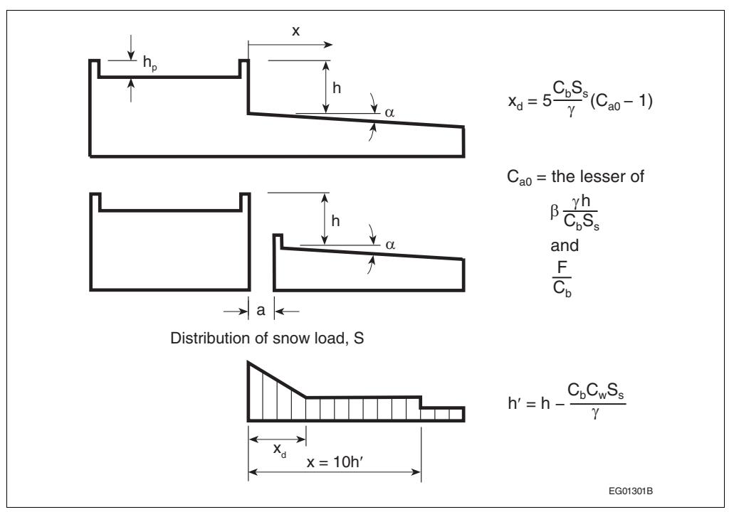
Snow Load Factors for Lower Level Roofs
Forming Part of Sentences 4.1.6.5.(1) and (3), Table 4.1.6.5.-A and Sentence 4.1.6.6.(1)
Notes to Figure 4.1.6.5.-A:
- If a > 5 m or h 0.8 Ss/ , drifting from the higher roof need not be considered.
- If h ≥ 5 m, the value of Ca0 for Case I is permitted to be determined in accordance with Sentence 4.1.6.5.(4).
Table 4.1.6.5.-A Wind Exposure, Slope and Accumulation Factors in Figure 4.1.6.5.-A
Forming Part of Sentence 4.1.6.5.(1)
| Distance from Roof Step, x | Factor Cw | Factor Cs[1] | Factor Ca |
|---|---|---|---|
| 0 | 1.0 | f(α) | Ca0 |
| 0 < x ≤ xd | 1.0 | f(α) | Ca0 − (Ca0 − 1)(x/xd) |
| xd < x ≤ 10 h' | 1.0 | f(α) | 1.0 |
| x > 10 h' | 1.0 for unexposed roof areas | f(α) | 1.0 |
| x > 10 h' | 0.75 for exposed roof areas | f(α) | 1.0 |
| x > 10 h' | 0.5 for exposed roof areas north of tree line | f(α) | 1.0 |
Notes to Table 4.1.6.5.-A:
- For lower roofs with parapets, Cs = 1.0; otherwise, Cs varies as a function of slope, α, as defined in Sentences 4.1.6.2.(5) and (6).
- The length of the drift, , shall be calculated as follows:
where
- = specific weight of snow as specified in Article 4.1.6.13.
- Except as provided in Sentence (4), the value of Ca0 for each of Cases I, II and III shall be the lesser of
and
where
- for Case I and 0.67 for Cases II and III,
- h = difference in elevation between the lower roof surface and the top of the parapet on the upper roof as shown in Figure 4.1.6.5.-A, and
, but for
where
- = value for applicable to the source of drifting,
- respectively the shorter and longer dimensions of the relevant source areas for snow drifting shown in Figure 4.1.6.5.-B for Cases I, II and III, and
, but
where
- = height of the roof perimeter parapet of the source area, to be taken as zero unless all the roof edges of the source area have parapets.
- Where m, the value of for Case I is permitted to be taken as
- The value of shall be the highest of Cases I, II and III, considering the different roof source areas for drifting snow, as specified in Sentences (3) and (4) and Figure 4.1.6.5.-B.
Figure 4.1.6.5.-B — Snow Load Cases I, II and III for Lower Level Roofs — Forming Part of Sentences 4.1.6.5.(1), (3) and (5), and Table 4.1.6.5.-B
Figure 4.1.6.5.-B Snow Load Cases I, II and III for Lower Level Roofs Forming Part of Sentences 4.1.6.5.(1), (3) and (5), and Table 4.1.6.5.-B
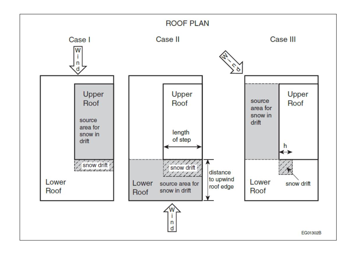
4.1.6.5.-B — Parameters for Snow Load Cases in Figure 4.1.6.5.-B
Forming Part of Sentences 4.1.6.5.(1), (3) and (5)
| Parameter | Case I | Case II | Case III |
|---|---|---|---|
| β | 1.0 | 0.67 | 0.67 |
| hp | parapet height of upper-roof source area | parapet height of lower-roof source area | parapet height of lower-roof source area |
| lcs = 2 ws − ws²/ls | with ws and ls being the shorter and longer dimensions of the upper roof | with ws and ls being the shorter and longer dimensions of the source area on the lower roof for upwind-facing step | with ws and ls being the shorter and longer dimensions of the source area on the lower roof for downwind-facing step |
4.1.6.6. Horizontal Gap Between a Roof and a Higher Roof
- Where the roof of one building is separated by a distance, a, from an adjacent building with a higher roof as shown in Figure 4.1.6.5.-A, the influence of the adjacent building on the value of the accumulation factor, , for the lower roof shall be determined as follows:
- if a > 5 m, the influence of the adjacent building on for the lower roof can be ignored, and
- if m, for the lower roof shall be calculated in accordance with Article 4.1.6.5. for values of .
4.1.6.7. Areas Adjacent to Roof Projections
- Except as provided in Sentences (2) and (3), the accumulation factor, , for areas adjacent to roof-mounted vertical projections shall be calculated in accordance with Sentence 4.1.6.5.(1) using the following values for the peak accumulation factor, , and the drift length, :
- shall be taken as the lesser of,
- shall be taken as the lesser of 3.35 h and , where h = height of the projection, and horizontal dimension of the projection. (See Note A-4.1.6.7.(1))
and , and
- Ca is permitted to be calculated in accordance with Article 4.1.6.5. for larger projections. (See Note A-4.1.6.7.(2))
- Where the longest horizontal dimension of the roof projection, , is less than 3 m, the drift surcharge adjacent to the projection need not be considered.
4.1.6.8. Snow Drift at Corners
- The drift loads on the lower level roof against the two faces of an outside corner of an upper level roof or roof obstruction shall be extended radially around the corner as shown in Figure 4.1.6.8.-A and may be taken as the least severe of the drift loads lying against the two faces of the corner.
- The drift loads on the lower level roof against the two faces of an inside corner of an upper level roof or a parapet shall be calculated for each face and the higher of the two loads shall be applied where the drifts overlap as shown in Figure 4.1.6.8.-B.
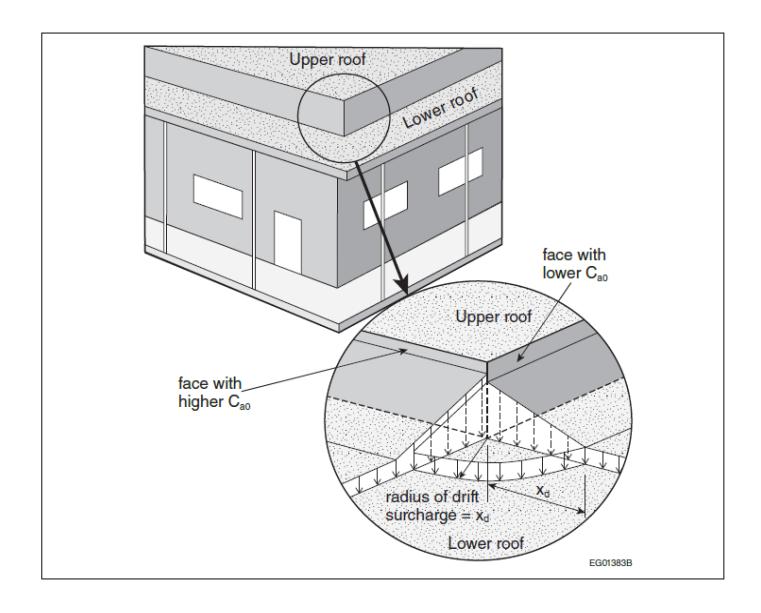
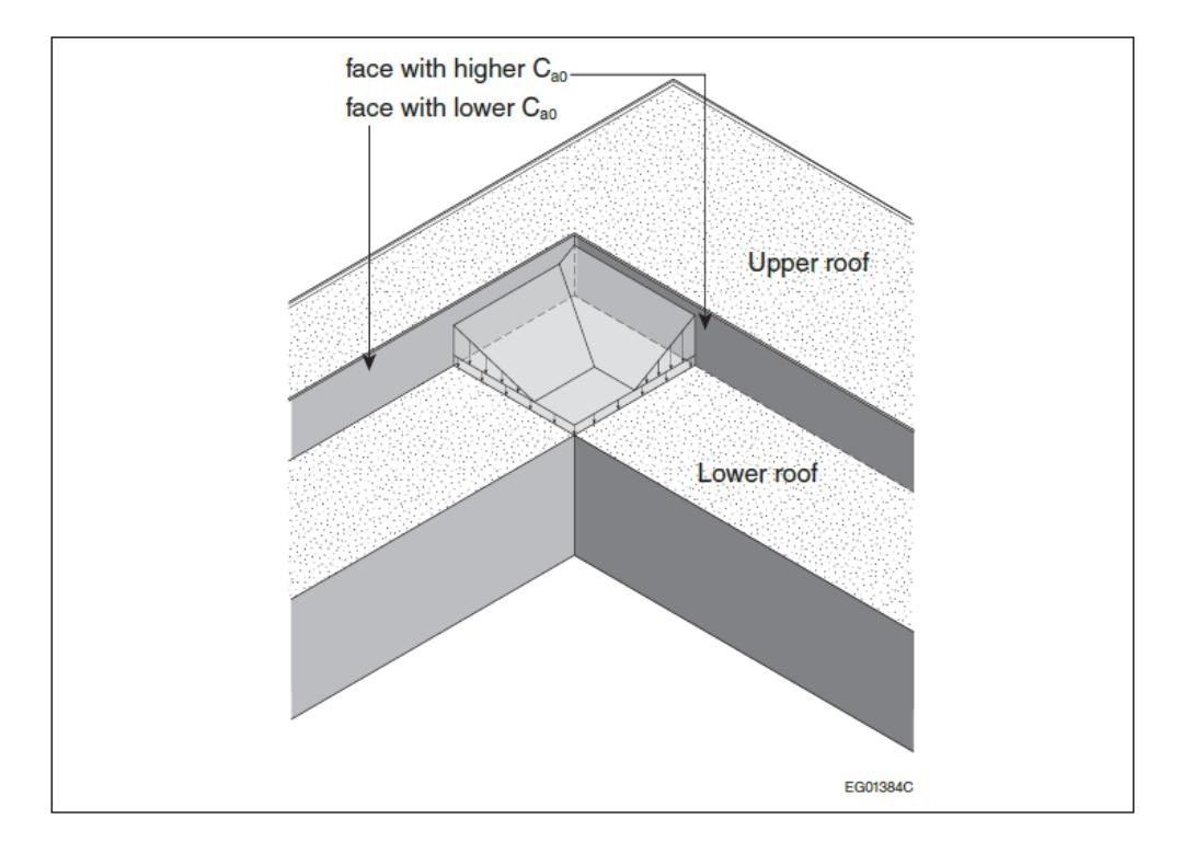
4.1.6.9. Gable Roofs (See Note A-4.1.6.9.)
- For all gable roofs, the full and partial load cases defined in Article 4.1.6.3. shall be considered.
- For gable roofs with a slope of , the unbalanced load case shall also be considered by setting the values of the accumulation factor, , as follows:
- on the upwind side of the roof peak, Ca shall be taken as 0, and
- on the downwind side of the roof peak, shall be taken as
- , where , and
- 1.25, where .
- For all gable roofs, the slope factor, Cs, shall be as prescribed in Sentences 4.1.6.2.(5) and (6).
- For all gable roofs, the wind exposure factor, , shall be
- as prescribed in Sentences 4.1.6.2.(3) and (4) for the full and partial load cases, and
- 1.0 for the unbalanced load case referred to in Sentence (2).
4.1.6.10. Arch Roofs, Curved Roofs and Domes
- For all arch roofs, curved roofs and domes, the full and partial load cases defined in Article 4.1.6.3. shall be considered.
- For arch roofs, curved roofs and domes with rise-to-span ratio h/b > 0.05 (See Figure 4.1.6.10.-A), the load cases provided in Sentences (3) to (7) shall also be considered.
- For arch roofs with a slope at the edge (See Figure 4.1.6.10.-A and Table 4.1.6.10.), shall be
- taken as 0 on the upwind side of the peak, and
- on the downwind side of the peak, taken as
for and
for
where
- x = horizontal distance from the roof peak,
- h = height of arch, and
- b = width of arch.
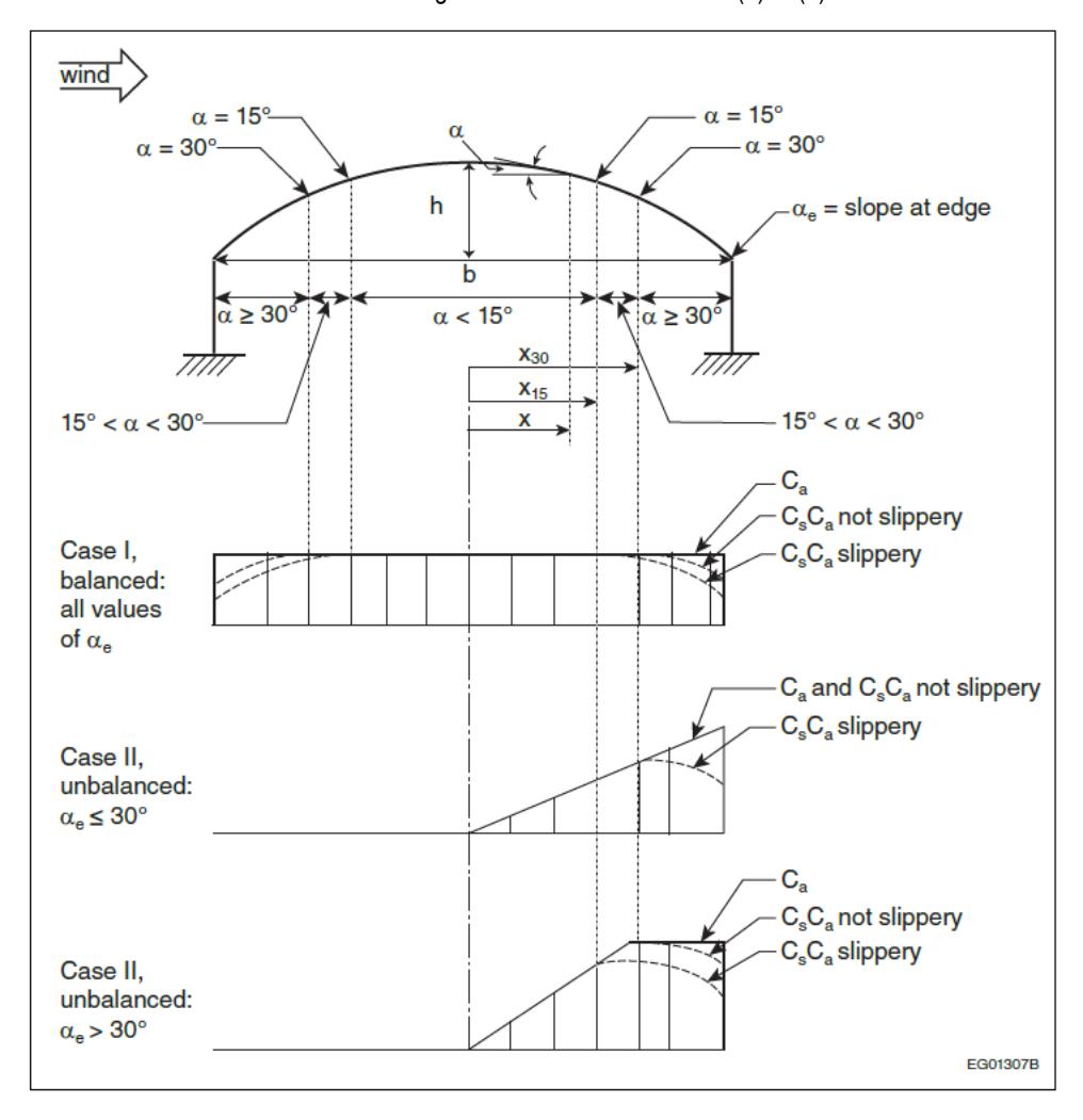
Accumulation Factors for Arch Roofs and Curved Roofs Forming Part of Sentences 4.1.6.10.(2) to (4)
Notes to Figure 4.1.6.10.-A:
- Refer to Table 4.1.6.10. for applicable values of Cw and Sentences 4.1.6.2.(5) and (6) for applicable values of Cs.
Table 4.1.6.10. Load Cases for Arch Roofs, Curved Roofs and Domes
Forming Part of Sentences 4.1.6.10.(1) and (3), 4.1.6.11.(1) and 4.1.6.12.(1)
| Load Case | Range of Application | Arch Roofs, Curved Roofs and Domes, Cw | Arch and Curved Roofs, Ca Upwind Side | Arch and Curved Roofs, Ca Downwind Side | Domes, Ca Downwind Side |
|---|---|---|---|---|---|
| Case I | All values of h/b | As stated in 4.1.6.2.(3) and (4) | 1.0 | 1.0 | 1.0 |
| Case II | Slope at edge ≤ 30°, h/b > 0.05, all values of x | 1.0 | 0.0 | Ca = (xh) / (0.03Cbb2) for h/b ≤ 0.12 Ca = (4x) / (Cbb) for h/b > 0.12 | Ca(x,y) = Ca(x,0) (1 − y/r) |
| Case II | Slope at edge > 30°, h/b > 0.05, 0 < x < x30 | 1.0 | 0.0 | Ca = (xh) / (0.06Cbx30b) for h/b ≤ 0.12 Ca = (2x) / (Cbx30) for h/b > 0.12 | Ca(x,y) = Ca(x,0) (1 − y/r) |
| Case II | Slope at edge > 30°, h/b > 0.05, x ≥ x30 | 1.0 | 0.0 | Ca = h / (0.06Cbb) for h/b ≤ 0.12 Ca = 2 / Cb for h/b > 0.12 | Ca(x,y) = Ca(x,0) (1 − y/r) |
- For arch roofs with a slope at the edge (See Figure 4.1.6.10.-A and Table 4.1.6.10.), shall be
- taken as 0 on the upwind side of the peak, and
- on the downwind side of the peak,
- for the part of the roof between the peak and point where the slope , taken as,
for , and
where
- x, h, b = as specified in Sentence (2), and = value of x where the slope , and
- for the part of the roof where the slope , taken as,
for , and
for
- Except as provided in Sentence (6), for curved roofs shall be determined in accordance with the requirements for arch roofs stated in Sentences (3) and (4).
- Where the slope, , of a curved roof at its peak is greater than 10°, shall be determined in accordance with the requirements for gable roofs stated in Article 4.1.6.9. using a slope equal to the mean slope of the curved roof.
- For domes of circular plan form (see Figure 4.1.6.10.-B), Ca shall
- along the central axis parallel to the wind, vary in the same way as for an arch roof with the same rise-to-span ratio, h/b, and
- off this axis, vary according to
where
- = value of at location (x,y),
- = value of on the central axis parallel to the wind,
- x = distance along the central axis parallel to the wind,
- y = horizontal coordinate normal to the x direction, and
- r = radius of dome.
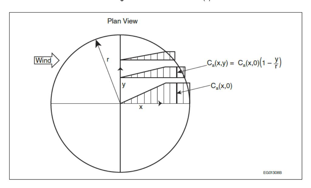
Notes to Figure 4.1.6.10.-B:
- Refer to Table 4.1.6.10. for applicable values of Cw and Sentences 4.1.6.2.(5) and (6) for applicable values of Cs.
- Refer to Sentences 4.1.6.10.(3) and (4) for the calculation of Ca(x,0).
- For all arch roofs, curved roofs and domes, the slope factor, , shall be as prescribed in Sentences 4.1.6.2.(5) and (6).
- For all arch roofs, curved roofs and domes, the wind exposure factor, Cw, shall be as prescribed in Table 4.1.6.10.
4.1.6.11. Snow Loads Due to Sliding
- Except as provided in Sentence (2), where an upper roof, or part thereof, slopes downwards with a slope towards a lower roof, the snow load, S, on the lower roof, determined in accordance with Articles 4.1.6.2. and 4.1.6.5., shall be augmented in accordance with Sentence (3) to account for the additional load resulting from sliding snow.
- Sentence (1) need not apply where
- snow from the upper roof is prevented from sliding by a parapet or other effective means, or
- the upper roof is not considered slippery and has a slope less than 20°.
- The total weight of additional snow resulting from sliding shall be taken as half the total weight of snow resulting from the uniform load case prescribed in Article 4.1.6.2. with
- the accumulation factor for the relevant part of the upper roof,
- the slope factor, Cs, based on the slope of the lower roof, as prescribed in Sentences 4.1.6.2.(5) and (6), and
- the sliding snow distributed on the lower roof such that it is a maximum for x = 0 and decreases linearly to 0 at , as shown in Figure 4.1.6.11., where x and are as defined in Article 4.1.6.5.
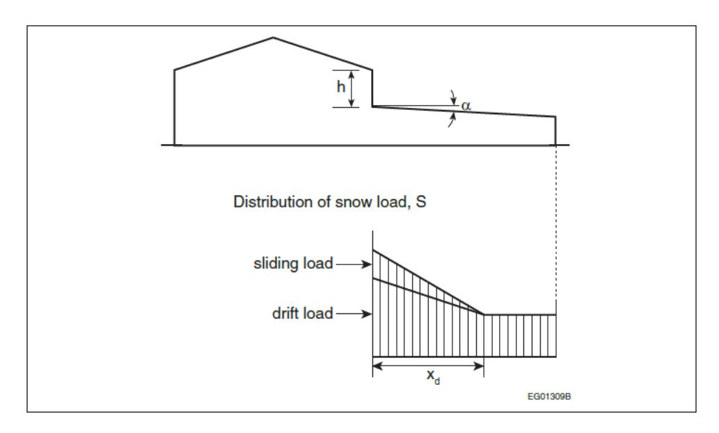
4.1.6.12. Valleys in Curved or Sloped Roofs
- For valleys in curved or sloped roofs with a slope , in addition to the full and partial load cases defined in Article 4.1.6.3., the non-uniform load Cases II and III presented in Sentences (2) and (3) shall be considered to account for sliding, creeping and movement of meltwater.
- For Case II (See Figure 4.1.6.12.), the accumulation factor, Ca, shall be calculated as follows:
for , and
for
where
- x = horizontal distance from the bottom of the valley, and
- b = twice the horizontal distance between the bottom of the valley and the peak of the roof surface in question.
- For Case III (See Figure 4.1.6.12.), Ca shall be calculated as follows:
for
where
- x, b = as specified in Sentence (2).
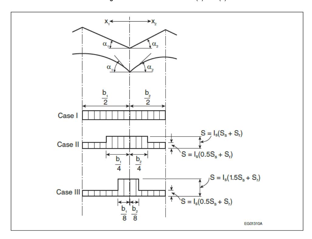
Snow Loads in Valleys of Sloped or Curved Roofs Forming Part of Sentences 4.1.6.12.(2) and (3)
Notes to Figure 4.1.6.12.:
- , as per Sentence 4.1.6.2.(3).
- , as per Sentence 4.1.6.2.(7).
4.1.6.13. Specific Weight of Snow
- For the purposes of calculating snow loads in drifts, the specific weight of snow, , shall be taken as 4.0 kN/m3 or 0.43 SS + 2.2 kN/m3, whichever is lesser.
4.1.6.14. Snow Removal
- Snow removal by mechanical, thermal, manual or other means shall not be used as a rationale to reduce design snow loads.
4.1.6.15. Ice Loading of Structures
- For lattice structures connected to the building, and other building components or appurtenances involving small width elements subject to significant ice accretion, the weight of ice accretion and the effective area presented to wind shall be as prescribed in CAN/CSA-S37, "Antennas, towers, and antenna-supporting structures."
4.1.6.16. Roofs with Solar Panels (See Note A-4.1.6.16.)
- Where solar panels are installed on a roof, the snow loads, S, shall be determined in accordance with Sentences (2) to (6) or with the requirements for roofs without solar panels, whichever produces the most critical effect.
- For the purposes of this Article, solar panels shall be classified as
- Parallel Flush, where the panels are installed parallel to the roof surface with their upper surface less than or equal to above the roof surface,
- Parallel Raised, where the panels are installed parallel to the roof surface with their upper surface greater than above the roof surface, or
- Tilted, where the panels are installed at an angle to the roof surface with their highest edge greater than CbCwSs/γ above the roof surface.
- For sloped roofs with solar panels, the snow loads, S, shall be determined in accordance with the requirements for roofs without solar panels, except that the slope factor, , shall be
- taken as 1.0 for roof areas extending upslope from the downslope edge of a panel or array of panels at an angle of from each side edge of the panel or array, and
- as specified in Sentences 4.1.6.2.(5) to (7) for all other roof areas. (See Note A-4.1.6.16.(3))
- For sloped roofs with Parallel Flush solar panels, the snow loads, S, shall be determined in accordance with the requirements for roofs without solar panels, except that
- Cs shall be determined in accordance with Sentence (3),
- where the gap width, , between the panels along the roof slope is greater than or equal to the panel width, , along the roof slope, the accumulation factor, , shall be taken as
- 0.0 for the panels,
- 2.0 for roof areas within a distance of wp downslope from a downslope panel edge, and
- 1.0 for all other roof areas, and (See Note A-4.1.6.16.(4)(b))
- where the gap width, , between the panels along the roof slope is less than the panel width, , along the roof slope, shall be taken as
- 0.0 for panel areas within a distance of wg downslope from an upslope panel edge,
- 1.0 for other panel areas,
- 2.0 for roof areas in gaps between the panels, and
- 1.0 for all other roof areas. (See Note A-4.1.6.16.(4)(c))
- For roofs with Parallel Raised solar panels, the snow loads, S, shall be determined in accordance with the requirements for roofs without solar panels, except that
- where the roof is flat, Ca shall be taken as
- 1.0 for the panels,
- 1.0 for roof areas not under the panels,
- 1.0 for roof areas under the panels within a distance of min (2 hg,2 wg) from a panel edge, where hg is the gap height between the lower surface of the panels and the roof surface, and wg is the gap width between the panels, and
- 0.0 for other roof areas under the panels, and
- where the roof is sloped, the snow loads, S, derived from Clause (a) shall be used, except that
- S shall be taken as 0.0 on the panels, and
- S for all roof areas shall be taken as the sum of S on the panels, as derived from Subclause (a)(i) and shifted by a distance of downslope onto the roof, where is the panel width along the roof slope, and S on the roof areas, as derived from Subclauses (a)(ii) to (a)(iv).(See Note A-4.1.6.16.(5)(a) and (b))
- where the roof is flat, Ca shall be taken as
- For flat roofs with Tilted solar panels, the snow loads, S, shall be determined in accordance with the requirements for roofs without solar panels, except that
- Ca shall be taken as 0.0 for the panels,
- shall be taken as 1.0 for roof areas beyond a distance of from the lowest edge of the panels, where h is the height of the highest edge of the panels above the roof surface,
- except as provided in Clauses (d) and (e), for roof areas within a distance of from the lowest edge of the panels, shall be taken as
- 1.25 for m, where is the gap height between the lowest edge of the panels and the roof surface,
- for m, and
- 1.0 for ,
(See Note A-4.1.6.16.(6)(c))
- except as provided in Clause (e), Ca shall be taken as 2.0 for roof areas within a distance of beyond the lowest edge of the panels, where is the horizontal projection of the panel width, , along the sloped panel edges, and
- where the panels, panel supports or back plates obstruct snow from sliding under the panels, the load of the increased volume of snow in the gaps between the panels shall be considered to be uniformly distributed.
(See Note A-4.1.6.16.(6))
4.1.7. Wind Load
4.1.7.1. Specified Wind Load
- The specified wind loads for a building and its components shall be determined using the Static, Dynamic or Wind Tunnel Procedure as stated in Sentences (2) to (5).
- For the design of buildings that are not dynamically sensitive, as defined in Sentence 4.1.7.2.(1), one of the following procedures shall be used to determine the specified wind loads:
- the Static Procedure described in Article 4.1.7.3.,
- the Dynamic Procedure described in Article 4.1.7.8., or
- the Wind Tunnel Procedure described in Article 4.1.7.14.
- For the design of buildings that are dynamically sensitive, as defined in Sentence 4.1.7.2.(2), one of the following procedures shall be used to determine the specified wind loads:
- the Dynamic Procedure described in Article 4.1.7.8., or
- the Wind Tunnel Procedure described in Article 4.1.7.14.
- For the design of buildings that may be subject to wake buffeting or channelling effects from nearby buildings, or that are very dynamically sensitive, as defined in Sentence 4.1.7.2.(3), the Wind Tunnel Procedure described in Article 4.1.7.14., shall be used to determine the specified wind loads.
- For the design of cladding and secondary structural members, one of the following procedures shall be used to determine the specified wind loads:
- the Static Procedure described in Article 4.1.7.3., or
- the Wind Tunnel Procedure described in Article 4.1.7.14.
- Computational fluid dynamics shall not be used to determine the specified wind loads for a building and its components. (See Note A-4.1.7.1.(6))
4.1.7.2. Classification of Buildings (See Note A-4.1.7.2.)
- Except as provided in Sentences (2) and (3), a building is permitted to be classified as not dynamically sensitive.
- A building shall be classified as dynamically sensitive if
- its lowest natural frequency is less than 1 Hz and greater than 0.25 Hz,
- its height is greater than 60 m, or
- its height is greater than 4 times its minimum effective width considering all wind directions, where the effective width, w, of a building shall be taken as,
where the summations are over the height of the building for a given wind direction, is the height above grade to level i, and is the width normal to the wind direction at height ; the minimum effective width is the lowest value of the effective width considering all wind directions.
- A building shall be classified as very dynamically sensitive if
- its lowest natural frequency is less than or equal to 0.25 Hz, or
- it contains a human occupancy, and its height is more than 6 times its minimum effective width as defined in Clause (2)(c).
4.1.7.3. Static Procedure
- The specified external pressure or suction due to wind on part or all of a surface of a building shall be calculated as follows:
where
- p = specified external pressure acting statically and in a direction normal to the surface, considered positive when the pressure acts towards the surface and negative when it acts away from the surface,
- = importance factor for wind load, as provided in Table 4.1.7.3.,
- q = reference velocity pressure, as provided in Sentence (4),
- = exposure factor, as provided in Sentences (5) and (7),
- = topographic factor, as provided in Article 4.1.7.4.,
- = gust effect factor, as provided in Sentence (8), and
- = external pressure coefficient, as provided in Articles 4.1.7.5. and 4.1.7.6.
Table 4.1.7.3. Importance Factor for Wind Load, Iw
Forming Part of Sentences 4.1.7.3.(1) and 4.1.7.8.(4)
| Importance Category | Importance Factor, Iw — ULS | Importance Factor, Iw — SLS |
|---|---|---|
| Low | 0.8 | 0.75 |
| Normal | 1.0 | 0.75 |
| High | 1.15 | 0.75 |
| Post-disaster | 1.25 | 0.75 |
- The net wind load for the building as a whole shall be the algebraic difference of the loads on the windward and leeward surfaces, and in some cases, may be calculated as the sum of the products of the external pressures or suctions and the areas of the surfaces over which they are averaged as provided in Sentence (1).
- The net specified pressure due to wind on part or all of a surface of a building shall be the algebraic difference, such as to produce the most critical effect, of the external pressure or suction calculated in accordance with Sentence (1) and the specified internal pressure or suction due to wind calculated as follows:
where
- = specified internal pressure acting statically and in a direction normal to the surface, either as a pressure directed toward the surface or as a suction directed away from the surface,
- , q, = as defined in Sentence (1),
- = exposure factor for internal pressure, as provided in Sentence (7),
- = internal gust effect factor, as provided in Sentence (10), and
- = internal pressure coefficient, as provided in Article 4.1.7.7.
- The reference velocity pressure, q, shall be the appropriate value determined in conformance with Subsection 1.1.3. based on a probability of being exceeded in any one year of 1 in 50.
- The exposure factor , shall be based on the reference height, h, determined in accordance with Sentence (6) for the surface or part of the surface under consideration and shall be
- (h/10)0.2 but not less than 0.9 for open terrain, where open terrain is level terrain with only scattered buildings, trees or other obstructions, open water or shorelines thereof,
- 0.7(h/12)0.3 but not less than 0.7 for rough terrain, where rough terrain is suburban, urban or wooded terrain extending upwind from the building uninterrupted for at least 1 km or 20 times the height of the building, whichever is greater, or
- an intermediate value between the two exposures defined in Clauses (a) and (b) in cases where the site is less than 1 km or 20 times the height of the building from a change in terrain conditions, whichever is greater, provided an appropriate interpolation method is used. (See Note A-4.1.7.3.(5)(c))
- The reference height, h, shall be determined as follows:
- for buildings with height less than or equal to 20 m and less than the smaller plan dimension, h shall be the midheight of the roof above grade, but shall not be less than 6 m,
- for other buildings, h shall be,
- for any structural element exposed to wind, h shall be the mid-height of the element above the ground.
- The exposure factor for internal pressure, Cei, shall be determined as follows:
- for buildings whose height is greater than 20 m and that have a dominant opening, Cei shall be equal to the exposure factor for external pressures, Ce, calculated at the mid-height of the dominant opening, and
- for other buildings, Cei shall be the same as the exposure factor for external pressures, Ce, calculated for a reference height, h, equal to the mid-height of the building or 6 m, whichever is greater.
- Except as provided in Sentences (9) and 4.1.7.6.(1), the gust effect factor, Cg, shall be one of the following values:
- 2.0 for the building as a whole and main structural members, or
- 2.5 for external pressures and suctions on secondary structural members including cladding.
- For cases where and are combined into a single product, , the values of and need not be independently specified. (See Article 4.1.7.6.)
- The internal gust effect factor, , shall be 2.0, except it is permitted to be calculated using the following equation for large structures enclosing a single large unpartitioned volume that does not have numerous overhead doors or openings:
where
- = internal volume in , and
- A = total area of all exterior openings of the volume in .
(See Note A-4.1.7.3.(10))
4.1.7.4. Topographic Factor
- Except as provided in Sentence (2), the topographic factor, Ct, shall be taken as 1.0.
- For buildings on hills or escarpments with slope, , greater than 0.1 (See Figure 4.1.7.4.), the topographic factor, , shall be calculated as follows:
where
where
- = applicable value from Table 4.1.7.4.,
- x = horizontal distance from the peak of the hill or escarpment,
- = horizontal distance upwind from the peak to the point where the ground surface lies at half the height of the hill or escarpment, or (where is the height of the hill or escarpment), whichever is greater,
- Z =height above ground, and
- k and based on shape of hill or escarpment.
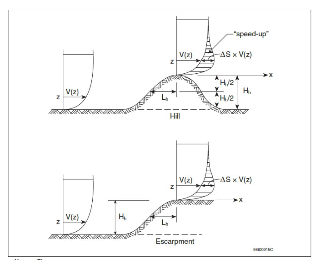
Speed-up of Mean Velocity on a Hill or Escarpment Forming Part of Sentence 4.1.7.4.(2)
Notes to Figure 4.1.7.4.:
- V(z) = wind speed.
Table 4.1.7.4. Parameters for Maximum Speed-Up over Hills and Escarpments
Forming Part of Sentence 4.1.7.4.(2)
| Shape of Hill or Escarpment | ΔSmax[1] | α | k (where x < 0) | k (where x ≥ 0) |
|---|---|---|---|---|
| 2-dimensional hill | 2.2 Hh /Lh | 3 | 1.5 | 1.5 |
| 2-dimensional escarpment | 1.3 Hh /Lh | 2.5 | 1.5 | 4 |
| 3-dimensional axi-symmetrical hill | 1.6 Hh /Lh | 4 | 1.5 | 1.5 |
Notes to Table 4.1.7.4.:
- For , assume and substitute for in the equation for .
4.1.7.5. External Pressure Coefficients
- Applicable values of external pressure coefficients, Cp, are provided in
- Sentences (2) to (9), and
- Article 4.1.7.6. for certain shapes of low buildings.
- For the design of the main structural system, the value of shall be established as follows, where H is the height of the building and D is the width of the building parallel to the wind direction:
- on the windward face,
C subscript p equals 0.6 when H divided by D is less than 0.25, equals 0.27 times the quantity H divided by D plus 2 when H divided by D is greater than or equal to 0.25 and less than 1.0, and equals 0.8 when H divided by D is greater than or equal to 1.0
- on the leeward face,
C subscript p equals negative 0.3 when H divided by D is less than 0.25, equals negative 0.27 times the quantity H divided by D plus 0.88 when H divided by D is greater than or equal to 0.25 and less than or equal to 1.0, and equals negative 0.5 when H divided by D is greater than or equal to 1.0
- on the walls parallel to the wind, .
(See Note A-4.1.7.5.(2) and (3))
- For the design of roofs, the value of shall be established as follows, where x is the distance from the upwind edge of the roof:
- for H/D 1.0, , and
- for H/D < 1.0,
(See Note A-4.1.7.5.(2) and (3))
- For the design of the cladding and of secondary structural elements supporting the cladding, the value of shall be established as follows, where W and D are the widths of the building:
- on walls, shall be taken as , except that within a distance equal to the larger of 0.1D and 0.1 W from a building corner, the negative value of shall be taken as -1.2,
- on walls where vertical ribs deeper than 1 m are placed on the facade, shall be taken as , except that, within a distance equal to the larger of 0.2D and 0.2 W from a building corner, the negative value of shall be taken as -1.4, and
- on roofs, shall be taken as -1.0, except that
- within a distance equal to the larger of 0.1D and 0.1 W from a roof edge, shall be taken as -1.5,
- in a zone that is within a distance equal to the larger of 0.2D and 0.2 W from a roof corner, Cp shall be taken as -2.3 but is permitted to be taken as -2.0 for roofs with perimeter parapets that are higher than 1 m, and
- on lower levels of flat stepped roofs, positive pressure coefficients established for the walls of the steps apply for a distance b. (See Figure 4.1.7.6.-D for the definition of b)
(See Note A-4.1.7.5.(4))
- Except as provided in Sentence (6), for the design of balcony guards, the internal pressure coefficient, , shall be taken as zero and the value of shall be taken as , except that, within a distance equal to the larger of 0.1D and 0.1 W from a building corner, shall be taken as .
- Where the top of the balcony guard is 2.0 m or less below the roof surface, the values of shall be taken as equal to those determined for parapets in Sentences (7) and (8).
- To determine the contribution from parapets to the wind loads on the main structural system, the values of shall be taken as
- on the outer faces, equal to those on the walls below,
- on the inner face of the windward parapet, equal to that on the upwind edge of a roof surface at the level of the top of the parapet, and
- on the inner faces of the other parapets, zero.
- For the structural design of parapets themselves, the values of shall be taken as equal to those specified in Sentence (7), except that the value of on the inner face of the leeward parapet shall be taken as equal to that on the outer face of the windward parapet.
- For the design of cladding on parapets, the values of Cp shall be taken as
- on the outer vertical surfaces, equal to those on the cladding on the walls below, and
- on the inner and top surfaces, equal to those on the cladding of a roof surface at the level of the top of the parapet.
4.1.7.6. External Pressure Coefficients for Low Buildings
- For the design of buildings with a height, H, that is less than or equal to 20 m and less than the smaller plan dimension, the values of the product of the pressure coefficient and gust factor, , provided in Sentences (2) to (9) are permitted to be used.
- For the design of the main structural system of the building, which is affected by wind pressures on more than one surface as shown in Figure 4.1.7.6.-A, the values of are provided in Table 4.1.7.6.
Table 4.1.7.6. External Peak Values of CgCp in Figure 4.1.7.6.-A
Forming Part of Sentence 4.1.7.6.(2)
| Load Case | Roof Slope | Building Surface 1 | Building Surface 1E | Building Surface 2 | Building Surface 2E | Building Surface 3 | Building Surface 3E | Building Surface 4 | Building Surface 4E | Building Surface 5 | Building Surface 5E | Building Surface 6 | Building Surface 6E |
|---|---|---|---|---|---|---|---|---|---|---|---|---|---|
| A | 0° to 5° | 0.75 | 1.15 | −1.3 | −2.0 | −0.7 | −1.0 | −0.55 | −0.8 | N/A | N/A | N/A | N/A |
| A | 20° | 1.0 | 1.5 | −1.3 | −2.0 | −0.9 | −1.3 | −0.8 | −1.2 | N/A | N/A | N/A | N/A |
| A | 30° to 45° | 1.05 | 1.3 | 0.4 | 0.5 | −0.7 | −1.0 | −0.7 | −0.9 | N/A | N/A | N/A | N/A |
| A | 90° | 1.05 | 1.3 | 1.05 | 1.3 | −0.7 | −0.9 | −0.7 | −0.9 | N/A | N/A | N/A | N/A |
| B | 0° to 90° | −0.85 | −0.9 | −1.3 | −2.0 | −0.7 | −1.0 | −0.85 | −0.9 | 0.75 | 1.15 | −0.55 | −0.8 |
Notes to Table 4.1.7.6.:
- For values of roof slope not shown, the coefficient CgCp can be interpolated linearly.
- Positive coefficients denote forces toward the surface, whereas negative coefficients denote forces away from the surface.
- For the design of individual walls and wall cladding, the values of are provided in Figure 4.1.7.6.-B.
- For the design of roofs with a slope less than or equal to , the values of are provided in Figure 4.1.7.6.-C.
- For the design of flat roofs with steps in elevation, the values of are provided in Figure 4.1.7.6.-D.
- For the design of gabled or hipped, single-ridge roofs with a slope greater than , the values of are provided in Figure 4.1.7.6.-E.
- For the design of gabled, multi-ridge roofs, the values of CgCp are provided in
- Figure 4.1.7.6.-C for roofs with a slope less than or equal to 10°, and
- Figure 4.1.7.6.-F for roofs with a slope greater than 10°.
- For monosloped roofs, the values of CgCp are provided in
- Figure 4.1.7.6.-C for roofs with a slope less than or equal to 3°, and
- Figure 4.1.7.6.-G for roofs with a slope greater than 3° and less than or equal to 30°.
- For sawtooth roofs, the values of CgCp are provided in
- Figure 4.1.7.6.-C for roofs with a slope less than or equal to 10°, and
- Figure 4.1.7.6.-H for roofs with a slope greater than 10°.
- The wind loads on balcony guards on low buildings shall be as specified in Sentences 4.1.7.5.(5) and (6).
- The wind loads on parapets on low buildings shall be as specified in Sentences 4.1.7.5.(7) to (9).
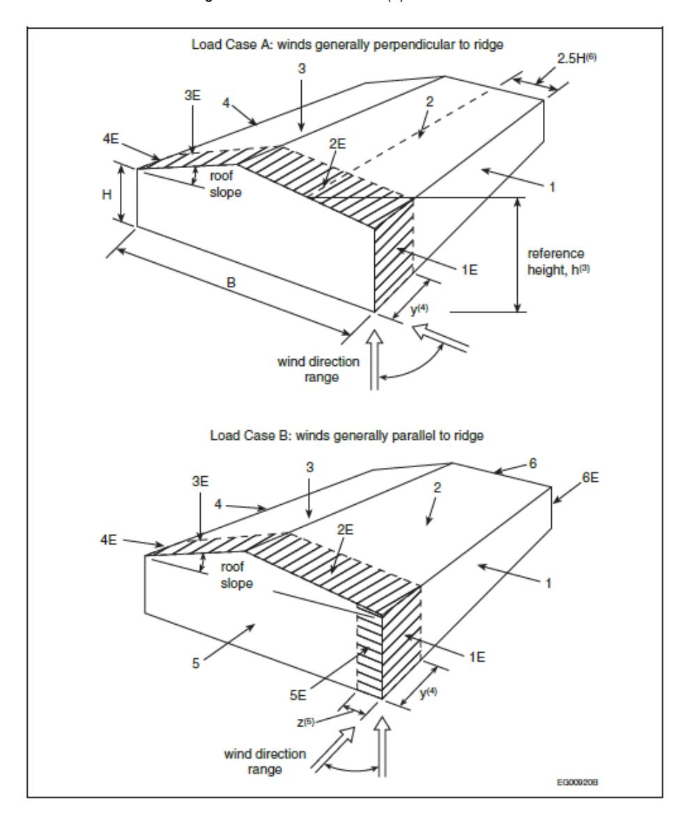
Primary Structural Actions Arising from Wind Load Acting Simultaneously on All Surfaces of Low Buildings (H ≤ 20 m)
Forming Part of Sentence 4.1.7.6.(2) and Table 4.1.7.6.
Notes to Figure 4.1.7.6.-A:
- The building must be designed for all wind directions. Each corner must be considered in turn as the windward corner shown in the sketches. For all roof slopes, Load Case A and Load Case B are required as two separate loading conditions to generate the wind actions, including torsion, to be resisted by the structural system.
- For the design of foundations, exclusive of anchorages to the frame, only 70% of the effective load is to be considered.
- The reference height, h, for pressures is the mid-height of the roof or 6 m, whichever is greater. The eave height, H, may be substituted for the mid-height of the roof if the roof slope is less than 7°.
- End-zone width y should be the greater of 6 m or 2z, where z is the width of the gable-wall end zone defined for Load Case B below. Alternatively, for buildings with frames, the end-zone width y may be the distance between the end and the first interior frame.
- End-zone width z is the lesser of 10% of the least horizontal dimension and 40% of height, H, but not less than 4% of the least horizontal dimension or 1 m.
- For B/H > 5 in Load Case A, the negative coefficients listed for surfaces 2 and 2E in Table 4.1.7.6. should only be applied on an area whose width is 2.5 H measured from the windward eave. The pressures on the remainder of the windward roof should be reduced to the pressures for the leeward roof.
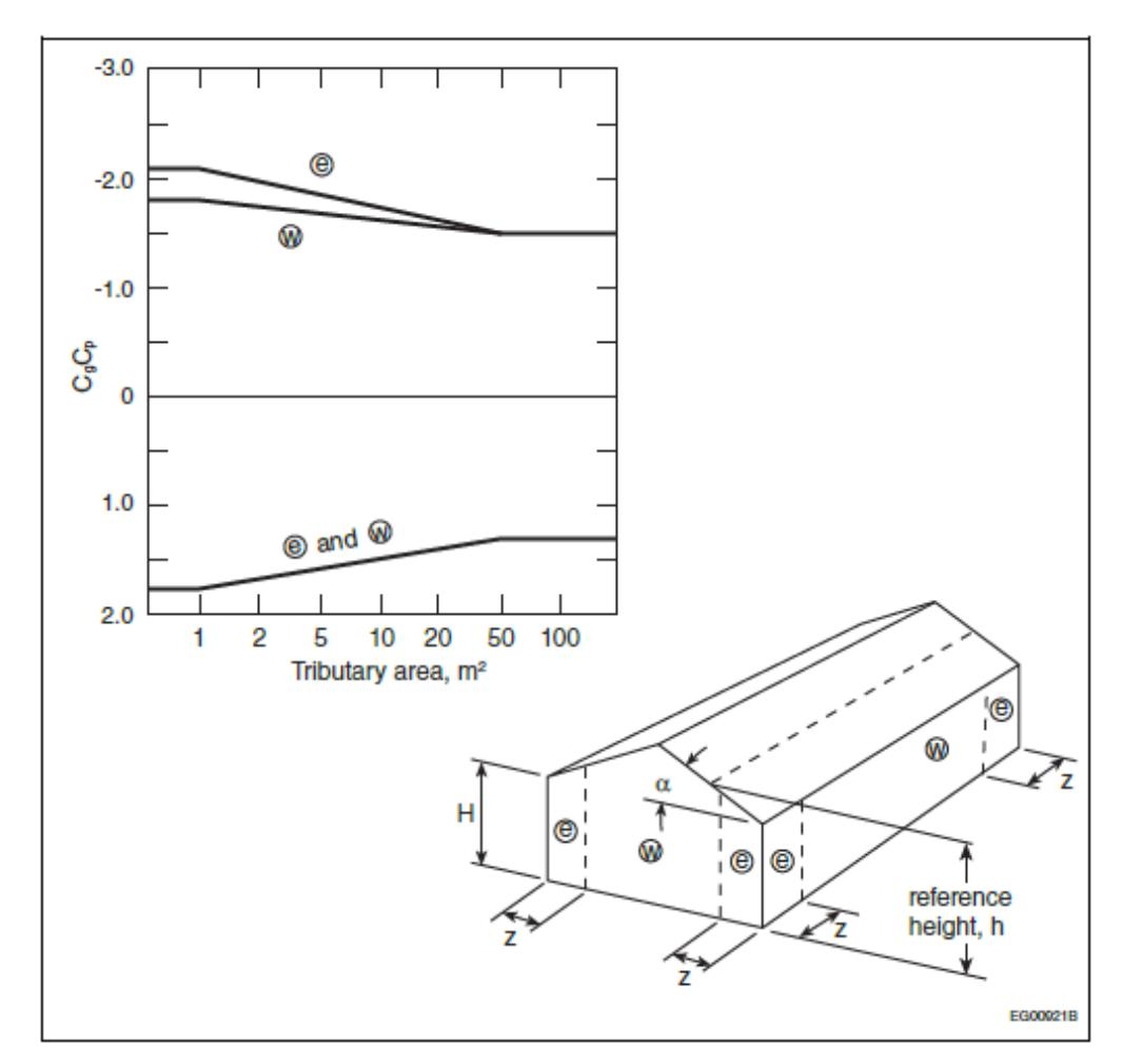
External Peak Values of CpCg on Individual Walls for the Design of Cladding and Secondary Structural Members
Forming Part of Sentence 4.1.7.6.(3)
Notes to Figure 4.1.7.6.-B:
- These coefficients apply for any roof slope, .
- End-zone width z is the lesser of 10% of the least horizontal dimension and 40% of height, H, but not less than 4% of the least horizontal dimension or 1 m.
- Combinations of external and internal pressures must be evaluated to obtain the most severe loading.
- Positive coefficients denote forces toward the surface, whereas negative coefficients denote forces away from the surface. Each structural element must be designed to withstand forces of both signs.
- Pressure coefficients generally apply for facades with architectural features; however, where vertical ribs deeper than 1 m are placed on a facade, a local CgCp of –2.8 applies to zone e.
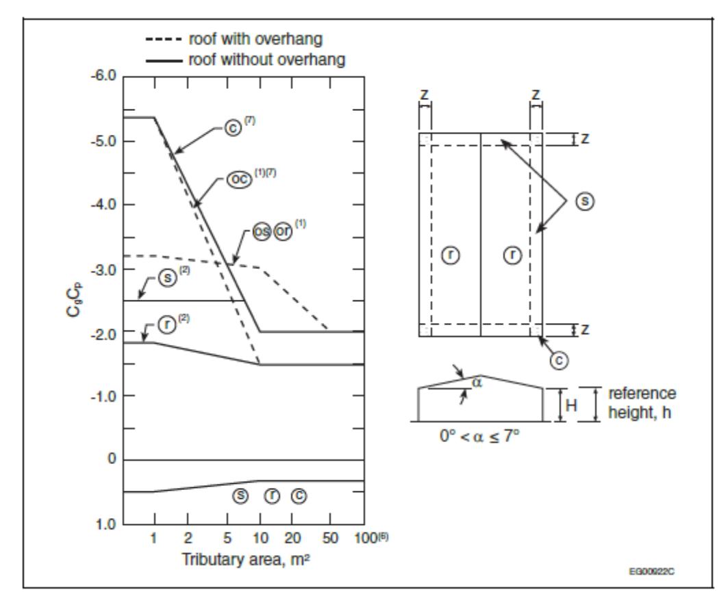
External Peak Values of CpCg on Roofs with a Slope of 7° or Less for the Design of Structural Components and Cladding
Forming Part of Sentences 4.1.7.6.(4), (7), (8), and (9)
Notes to Figure 4.1.7.6.-C:
- Coefficients for overhung roofs have the prefix "o" and refer to the same roof areas as referred to by the corresponding symbol without a prefix. They include contributions from both upper and lower surfaces. In the case of overhangs, the walls are inboard of the roof outline.
- s and r apply to both roofs and upper surfaces of canopies.
- End-zone width z is the lesser of 10% of the least horizontal dimension and 40% of height, H, but not less than 4% of the least horizontal dimension or 1 m.
- Combinations of external and internal pressures must be evaluated to obtain the most severe loading.
- Positive coefficients denote forces toward the surface, whereas negative coefficients denote forces away from the surface. Each structural element must be designed to withstand forces of both signs.
- For calculating the uplift forces on tributary areas larger than on unobstructed nearly-flat roofs with low parapets, and where the centre of the tributary area is at least twice the height of the building from the nearest edge, the value of may be reduced from -1.5 to -1.1 at x/H = 2 and further reduced linearly to -0.6 at x/H = 5, where x is the distance to the nearest edge and H is the height of the building.
- For roofs having a perimeter parapet with a height of 1 m or greater, the corner coefficients for tributary areas less than 1 m2 can be reduced from -5.4 to -4.4.
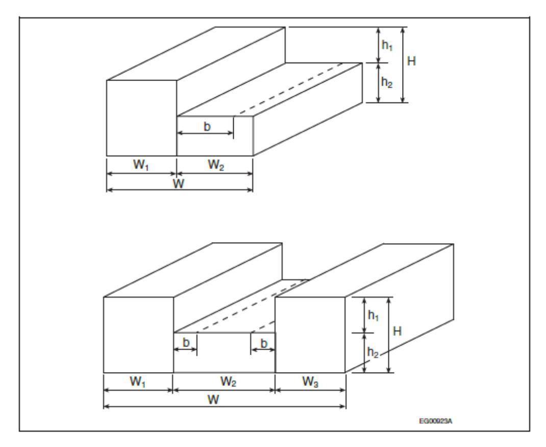
External Peak Values of CpCg for the Design of the Structural Components and Cladding of Buildings with Stepped Roofs
Forming Part of Sentence 4.1.7.6.(5)
Notes to Figure 4.1.7.6.-D:
- The zone designations, pressure-gust coefficients and notes provided in Figure 4.1.7.6.-C apply on both the upper and lower levels of flat stepped roofs, except that on the lower levels, positive pressure-gust coefficients equal to those in Figure 4.1.7.6.-B for walls apply for a distance, b, where b is equal to 1.5 h1 but not greater than 30 m. For all walls in Figure 4.1.7.6.-D, zone designations and pressure coefficients provided for walls in Figure 4.1.7.6.-B apply.
- Note (1) above applies only when the following conditions are met: , m, and , or is greater than 0.25 W but not greater than 0.75 W.
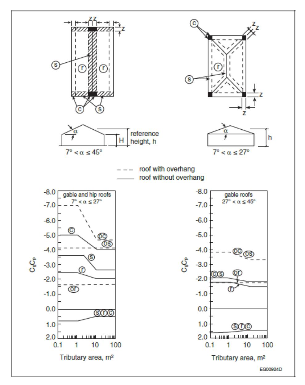
External Peak Values of CpCg on Single-Span Gabled and Hipped Roofs with a Slope Greater than 7° for the
Design of Structural Components and Cladding
Forming Part of Sentence 4.1.7.6.(6)
Notes to Figure 4.1.7.6.-E:
- Coefficients for overhung roofs have the prefix "o" and refer to the same roof areas as referred to by the corresponding symbol without a prefix. They include contributions from both upper and lower surfaces.
- End-zone width z is the lesser of 10% of the least horizontal dimension and 40% of height, H, but not less than 4% of the least horizontal dimension or 1 m.
- Combinations of external and internal pressures must be evaluated to obtain the most severe loading.
- Positive coefficients denote forces towards the surface, whereas negative coefficients denote forces away from the surface. Each structural element must be designed to withstand forces of both signs.
- For hipped roofs with , edge/ridge strips and pressure-gust coefficients for ridges of gabled roofs apply along each hip.
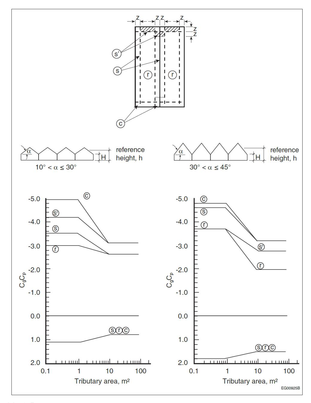
External Peak Values of CpCg on Multi-Span Gabled (Folded) Roofs with a Slope Greater than 10° for the Design of Structural Components and Cladding
Forming Part of Sentence 4.1.7.6.(7)
Notes to Figure 4.1.7.6.-F:
- End-zone width z is the lesser of 10% of the least horizontal dimension and 40% of height, H, but not less than 4% of the least horizontal dimension or 1 m.
- Combinations of external and internal pressures must be evaluated to obtain the most severe loading.
- Positive coefficients denote forces towards the surface, whereas negative coefficients denote forces away from the surface. Each structural element must be designed to withstand forces of both signs.
- For , the coefficients given in Figure 4.1.7.6.-C apply, but for cases where than 7°, use .
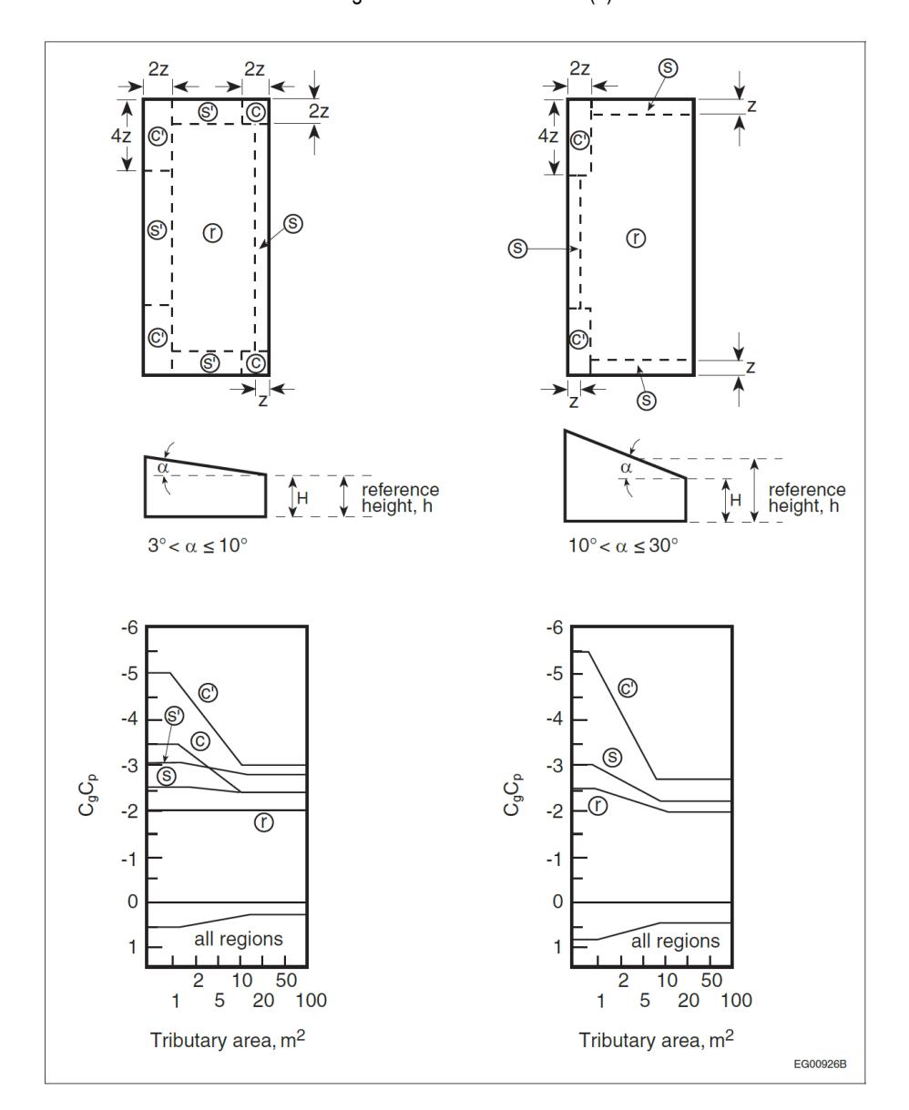
External Peak Values of CpCg on Monoslope Roofs for the Design of Structural Components and Cladding Forming Part of Sentence 4.1.7.6.(8)
Notes to Figure 4.1.7.6.-G:
- End-zone width, z, is the lesser of 10% of the least horizontal dimension and 40% of height, H, but not less than 4% of the least horizontal dimension or 1 m.
- Combinations of external and internal pressures shall be evaluated to obtain the most severe loading.
- Positive coefficients denote forces toward the surface, whereas negative coefficients denote forces away from the surface. Each structural element shall be designed to withstand forces of both signs.
- Where , the coefficients given in Figure 4.1.7.6.-C apply.
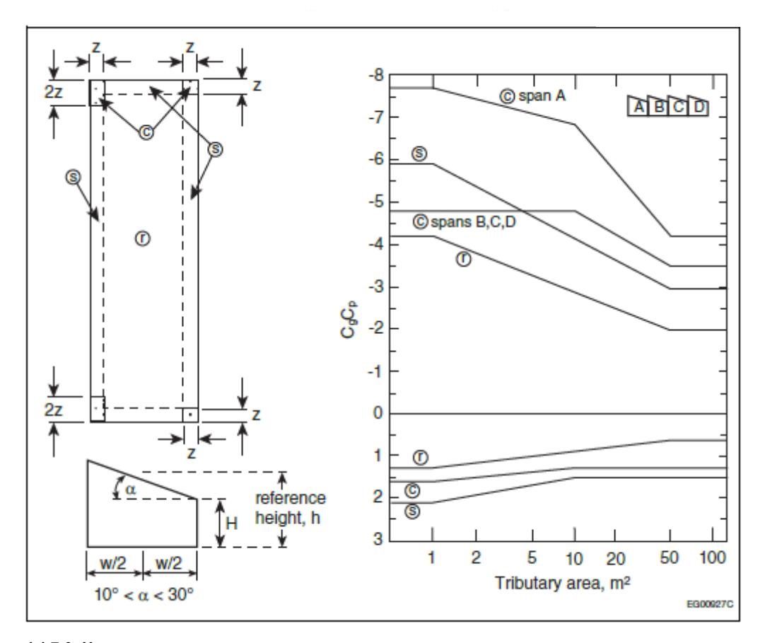
External Peak Values of CPCg on Sawtooth Roofs with a Slope Greater than 10° for the
Design of Structural Components and Cladding
Forming Part of Sentence 4.1.7.6.(9)
Notes to Figure 4.1.7.6.-H:
- End-zone width z is the lesser of 10% of the least horizontal dimension and 40% of height, H, but not less than 4% of the least horizontal dimension or 1 m.
- Combinations of external and internal pressures must be evaluated to obtain the most severe loading.
- Positive coefficients denote forces towards the surface, whereas negative coefficients denote forces away from the surface. Each structural element must be designed to withstand forces of both signs.
- Negative coefficients on the corner zones of Span A differ from those on Spans B, C and D.
- For , the coefficients given in Figure 4.1.7.6.-C apply, but for cases where , use .
4.1.7.7. Internal Pressure Coefficient
- The internal pressure coefficient, , for buildings shall be as prescribed in Table 4.1.7.7.
- The internal pressure coefficient, Cpi, for cladding on parapets shall be -0.70 to +0.70. (See Note A-4.1.7.7.(2))
Table 4.1.7.7. Internal Pressure Coefficients
Forming Part of Sentence 4.1.7.7.(1)
| Building Openings | Values for Cpi |
|---|---|
| Uniformly distributed small openings amounting to less than 0.1% of the total surface area of the building | |
| Non-uniformly distributed openings of which none is significant or significant openings that are wind-resistant and closed during storms | −0.45 to +0.30 |
| Large openings likely to remain open during storms | −0.70 to +0.70 |
4.1.7.8. Dynamic Procedure
- For the application of the Dynamic Procedure, the provisions of Article 4.1.7.3. shall be followed, except that the exposure factor, Ce, shall be as prescribed in Sentences (2) and (3), and the gust effect factor, Cg, shall be as prescribed in Sentence (4), when determining the wind loads on the main structural system.
- For buildings in open terrain, as defined in Clause 4.1.7.3.(5)(a), the value of for the design of the main structural system shall be calculated as follows:
, but
(See Note A-4.1.7.8.(2) and (3))
- For buildings in rough terrain, as defined in Clause 4.1.7.3.(5)(b), the value of for the design of the main structural system shall be calculated as follows:
, but
(See Note A-4.1.7.8.(2) and (3))
- For the design of the main structural system, Cg shall be calculated as follows:
where
, and
where
- ,
- T = 3600 s,
- K = 0.08 for open terrain and 0.10 for rough terrain,
- CeH = exposure factor evaluated at reference height h = H,
- B = background turbulence factor, a function of w/H determined from Figure 4.1.7.8.,
- s = size reduction factor calculated as
- = damping ratio, which shall be determined by a rational method or may be taken to be 0.01 for steel structures, 0.02 for concrete structures and 0.015 for composite structures,
where
- fnD = natural frequency of vibration of the building in the along-wind direction, in Hz,
- = lowest natural frequency of the building, in Hz, as described in Sentences 4.1.7.2.(2) and (3),
- H = height of the building,
- , where , and
- = mean wind speed at the top of the structure, in m/s, calculated as ,
where
- ,
where
- = importance factor for wind load, as provided in Table 4.1.7.3.,
- q = reference velocity pressure, in Pa, and
(See Note A-4.1.7.8.(4))
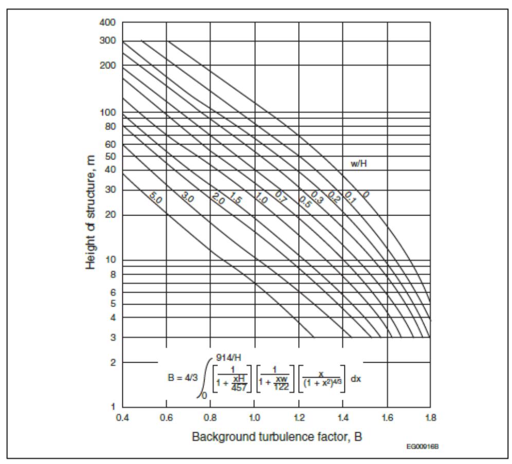
Background Turbulence Factor, B Forming Part of Sentence 4.1.7.8.(4)
4.1.7.9. Full and Partial Wind Loading
- Except where the wind loads are derived from the combined CgCp values determined in accordance with Article 4.1.7.6., buildings and structural members shall be capable of withstanding the effects of the following loads:
- the full wind loads acting along each of the 2 principal horizontal axes considered separately,
- 75% of the wind loads described in Clause (a) but offset from the central geometric axis of the building by 15% of its width normal to the direction of the force to produce the worst load effect,
- 75% of the wind loads described in Clause (a) but with both axes considered simultaneously, and
- 56% of the wind loads described in Clause (a) but with both axes considered simultaneously and offset from the central geometric axis of the building by 15% of its width normal to the direction of the force.
(See Note A-4.1.7.9.(1))
4.1.7.10. Interior Walls and Partitions
- In the design of interior walls and partitions, due consideration shall be given to differences in air pressure on opposite sides of the wall or partition which may result from
4.1.7.11. Exterior Ornamentations, Equipment and Appendages (See Note A-4.1.7.11.)
- The effects of wind loads on exterior ornamentations, equipment and appendages, including the increase in exposed area as a result of ice buildup as prescribed in CAN/CSA-S37, "Antennas, towers, and antenna-supporting structures," shall be considered in the structural design of the connections and the building.
- Where there are a number of similar components, the net increase in force is permitted to be based on the total area for all similar components as opposed to the summation of forces of individual elements.
4.1.7.12. Attached Canopies on Low Buildings with a Height H ≤ 20 m
(See Note A-4.1.7.12.)
- For the purposes of this Article, "attached canopy" shall mean a horizontal canopy with a maximum slope of 2% that is attached to a building wall at any height, hc, above ground level.
- The specified external wind pressure, p, and the specified net external wind pressure, , for attached canopies on exterior walls of low buildings with a height m shall be determined as follows:
, and
where
- p = specified external wind pressure acting statically and in a direction normal to the upper or lower surface of the canopy, considered positive when acting towards the surface and negative when acting away from the surface,
- = specified net external wind pressure acting statically on the canopy, considered positive when acting in a downward direction and negative when acting in an upward direction,
- , q, , = as defined in Sentence 4.1.7.3.(1),
- = gust pressure coefficient on the upper or lower surface of the canopy, as given in Figure 4.1.7.12.-A, and
- = net gust pressure coefficient on the canopy, considering simultaneous contributions from the upper and lower surfaces of the canopy, as given in Figure 4.1.7.12.-B.
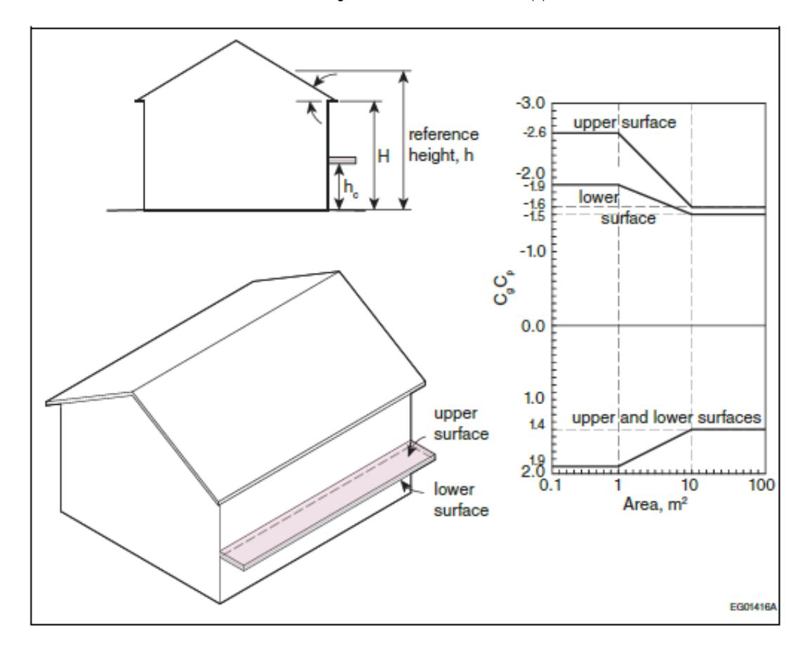
Gust Pressure Coefficients on the Upper and Lower Surfaces of Attached Canopies With no Gap Between the Canopy and the Building
Forming Part of Sentence 4.1.7.12.(2)
Notes to Figure 4.1.7.12.-A:
- The coefficients apply for any roof slope, a.
- The reference height, h, is the mid-height of the roof or 6 m, whichever is greater.
- Positive CgCp values denote forces acting towards the upper or lower surface of the canopy, whereas negative CgCp values denote forces acting away from the surface. Each structural element must be designed to resist both the positive and negative forces.
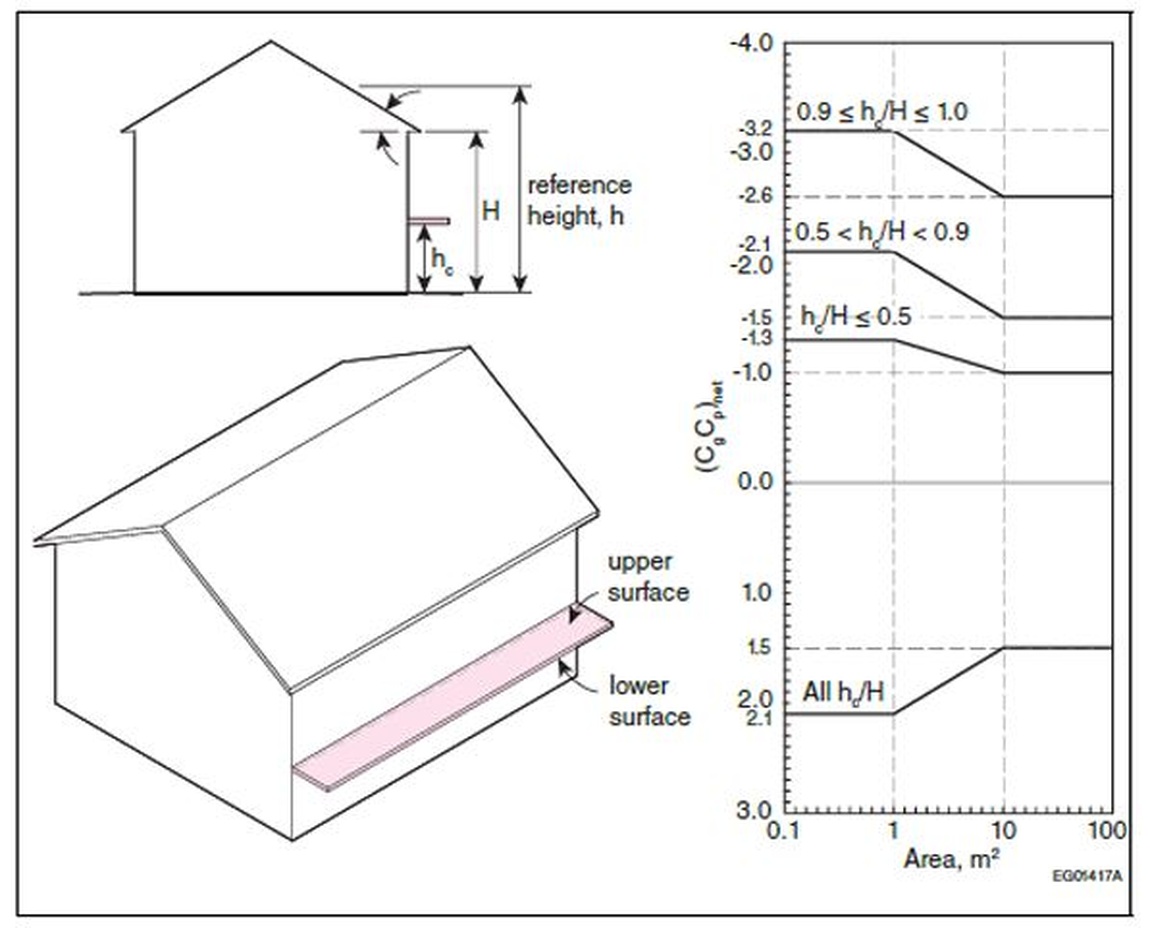
Net Gust Pressure Coefficients on Attached Canopies, Considering Simultaneous Contributions from the Upper and
Lower Surfaces of the Canopy
Forming Part of Sentence 4.1.7.12.(2)
Notes to Figure 4.1.7.12.-B:
- The coefficients apply for any roof slope, .
- The reference height, h, is the mid-height of the roof or 6 m, whichever is greater.
- Positive values denote net forces acting in a downward direction on the canopy, whereas negative values denote net forces acting in an upward direction on the canopy. The canopy must be designed to resist both the positive and negative net forces.
4.1.7.13. Roof-Mounted Solar Panels on Buildings of Any Height (See Note A-4.1.7.13.)
- Where solar panels are installed on a roof, the roof wind loads shall account for the wind loads on the solar panels, as determined in accordance with Sentences (2) to (7), or shall be determined in the same way as for the roof without solar panels, whichever approach results in the most critical effect.
- For an array of solar panels where the panels are installed close and parallel to the roof surface with their upper surface not more than 250 mm above the roof surface and with gaps around the panels of not less than 6 mm, the net positive or negative pressure difference between the upper and lower surfaces of a panel or the array shall be calculated as follows:
where
- , q, , , , = as defined in Sentence 4.1.7.3.(1), determined in the same manner as for the roof cladding,
- E =edge factor, as provided in Sentence (4), and
- = pressure equalization factor, as provided in Sentence (3).
- The pressure equalization factor, , in Sentence (2) shall be
- for a panel or an array where the panel chord length, Lp, is greater than 2 m or for a panel or an array that is within a distance of 2 h2 from the roof edge or ridge, where h2 is the height of the panel's highest point above the roof surface, taken as 1.0, and
- for other panels or arrays, determined from Figure 4.1.7.13.-A based on the area of the panel or array over which the wind load is being calculated.
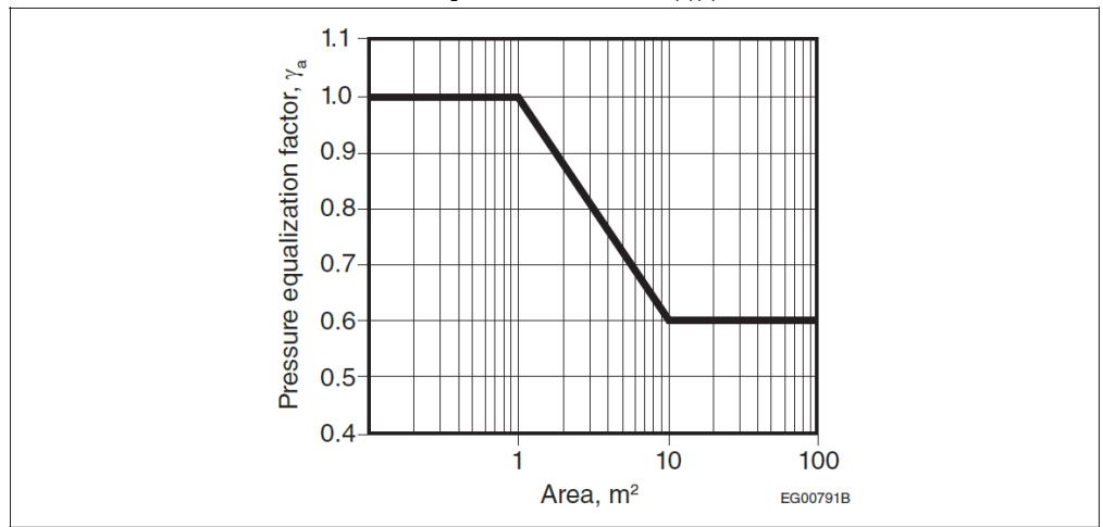
- The edge factor, E, in Sentence (2) shall be taken as
- 1.5 within a distance of 1.5 Lp from an exposed edge of the array of solar panels, as defined in Sentence (5), and
- 1.0 elsewhere.
- For the purposes of Clause (4)(a), an exposed edge of the array of solar panels shall be considered to occur
- where the distance to the next row of panels or the distance across a gap in the same row of panels exceeds 4 h2 or 1.2 m, whichever is greater, or
- where the distance to the roof edge exceeds 4 h2 or 1.2 m, whichever is greater, and exceeds 0.5 h, where h is the reference height of the roof.
- For an array of solar panels mounted on a roof with a slope, , less than or equal to , where the panels are tilted relative to the roof surface, have a chord length, , not greater than 2 m, and are installed such that the height of their lowest point above the roof surface, , is not greater than 0.6 m, the height of their highest point above the roof surface, , is not greater than 1.2 m, and their tilt angle relative to the roof surface, , is not greater than 35°, or where the panels are installed parallel to the roof surface with their upper surface greater than 250 mm above the roof surface and with gaps not less than 6 mm between the panels, the net positive or negative pressure difference between the upper and the lower surfaces of a panel or the array shall be calculated as follows:
where
- , q, , = as defined in Sentence 4.1.7.3.(1), determined in the same manner as for the roof cladding, and = net gust pressure coefficient, as provided in Sentence (7).
- The net gust pressure coefficient, , in Sentence (6) shall be calculated as follows:
where
- = parapet factor, determined as the lesser of 1.2 and (0.9 + hpt/h),
- = chord factor, determined as the greater of and 0.8,
- E = as defined in Sentence (2), and
- (CgCp)n = normalized gust pressure coefficient, determined from Figure 4.1.7.13.-B based on ω and AN,
where
- = height of the parapet above the roof surface, in m, h = reference height of the roof, in m,
- = panel chord length, in m,
- = panel tilt angle relative to the roof surface, and
- = normalized panel or array area, calculated as
where
- , and
- = normalized building length, in m, determined as the lesser of , h and ,
where
- WL = longest horizontal dimension of the building, in m, and
- = smallest horizontal dimension of the building, in m.
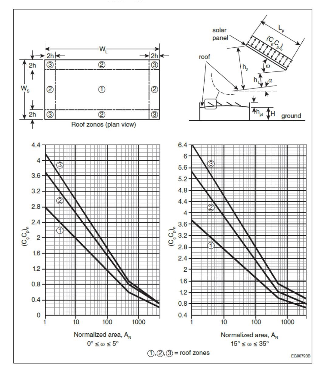
Normalized Gust Pressure Coefficient, (CgCp)N, for Solar Panels or Arrays Mounted on Low-Sloped Roofs of Buildings of Any Height
Forming Part of Sentence 4.1.7.13.(7)
Notes to Figure 4.1.7.13.-B:
- H = height of the building.
- h = reference height of the roof.
- (CgCp)n values are for both positive and negative values.
- For panels with 5° < w < 15°, linear interpolation is permitted.
4.1.7.14. Wind Tunnel Procedure
- Except as provided in Sentences (2) and (3), wind tunnel tests on scale models to determine wind loads on buildings shall be conducted in accordance with ASCE/SEI 49, "Wind Tunnel Testing for Buildings and Other Structures."
- Where an adjacent building provides substantial sheltering effect, the wind loads for the main structural system shall be no lower than 80% of the loads determined from tests referred to in Sentence (1) with the effect of the sheltering building removed as applied to
- the base shear force for buildings with ratio of height to minimum effective width, as described in Sentence 4.1.7.2.(2), less than or equal to 1.0, or
- the base moment for buildings with a ratio of height to minimum effective width greater than 1.0.
- For the design of cladding and secondary structural members, the exterior wind loads determined from the wind tunnel tests shall be no less onerous than those determined by analysis in accordance with Article 4.1.7.3. using the following assumptions:
- and , where the building's height is greater than 20 m or greater than its minimum effective width, and
- of the values for zones w and r provided in Article 4.1.7.6., where the building's height is less than or equal to 20 m and no greater than its minimum effective width.
4.1.8. Earthquake Load and Effects
4.1.8.1. Analysis
- Except as permitted in Sentence (2), the deflections and specified loading due to earthquake motions shall be determined according to the requirements of Articles 4.1.8.2. to 4.1.8.23.
- Where and are less than 0.16 and 0.03 respectively, the deflections and specified loading due to earthquake motions are permitted to be determined in accordance with Sentences (3) to (15), where
- IE is the earthquake importance factor and has a value of 0.8, 1.0, 1.3 and 1.5 for buildings in the Low, Normal, High and Post-disaster Importance Categories respectively,
- is the site coefficient based on the average or , as defined in Article 4.1.8.2., for the top 30 m of soil below the footings, pile caps or mat foundations and has a value of
- 1.0 for rock sites or when or kPa,
- 1.6 when or , and
- 2.8 for all other cases, and
- Sa(T, X450) is the 5%-damped spectral acceleration value at period T for site designation X450, as defined in Article 4.1.8.2., determined in accordance with Subsection 1.1.3. and corresponding to a 2% probability of exceedance in 50 years.
- The structure shall have a clearly defined
- seismic force resisting system (SFRS) to resist the earthquake loads and their effects, and
- load path (or paths) that will transfer the inertial forces generated in an earthquake to the supporting ground.
- An unreinforced masonry SFRS shall not be permitted where
- is greater than 1.0, or
- the height above grade is greater than or equal to 30 m.
- The height above grade of an SFRS designed in accordance with CSA S136, "North American Specification for the Design of Cold-Formed Steel Structural Members (using the Appendix B provisions applicable to Canada)," shall be less than 15 m.
- Earthquake forces shall be assumed to act horizontally and independently about any two orthogonal axes.
- The specified lateral earthquake force, , at the base of the structure in the direction under consideration shall be calculated as follows:
where
- for s, and
- over the height of the building, where is defined in Article 4.1.8.2., and
- , except for structures where the storey strength is less than that in the storey above and for an unreinforced masonry SFRS,
where
- Ts = fundamental lateral period of vibration of the building, as defined in Article 4.1.8.2.,
- = for steel moment frames,
- = for concrete moment frames,
- = 0.1N for other moment frames,
- for braced frames, and
- = for shear walls and other structures,
where
- = height, in m, above the base to level n, as defined in Article 4.1.8.2., and
- N = total number of storeys above exterior grade to level n, as defined in Article 4.1.8.2.,
except that, in cases where , need not be greater than .
- The total lateral earthquake design force, , shall be distributed over the height of the building in accordance with the following formula:
where
- = force applied through the centre of mass at level x,
- , = height, in m, above the base to level x or i respectively, as defined in Article 4.1.8.2.
- Accidental torsional effects applied concurrently with shall be considered by applying torsional moments about the vertical axis at each level for each of the following cases considered separately:
- , and
- .
- Deflections obtained from a linear analysis shall include the effects of torsion and be multiplied by to get realistic values of expected deflections.
- The deflections referred to in Sentence (10) shall be used to calculate the largest interstorey deflection, which shall not exceed
- 0.01 hs for post-disaster buildings,
- 0.02 hs for High Importance Category buildings, and
- for all other buildings,
where hs is the interstorey height as defined in Article 4.1.8.2.
- When earthquake forces are calculated using , the following elements in the SFRS shall have their design forces due to earthquake effects increased by 33%:
- diaphragms and their chords, connections, struts and collectors,
- tie downs in wood or drywall shear walls,
- connections and anchor bolts in steel- and wood-braced frames,
- connections in precast concrete, and
- connections in steel moment frames.
- Except as provided in Sentence (14), where cantilever parapet walls, other cantilever walls, exterior ornamentation and appendages, towers, chimneys or penthouses are connected to or form part of a building, they shall be designed, along with their connections, for a lateral force, , distributed according to the distribution of mass of the element and acting in the lateral direction that results in the most critical loading for design using the following equation:
where
- = weight of a portion of a structure as defined in Article 4.1.8.2.
- The value of Vsp shall be doubled for unreinforced masonry elements.
- Structures designed in accordance with this Article need not comply with the seismic requirements stated in the applicable design standard referenced in Section 4.3.
4.1.8.2. Notation
- In this Subsection,
- = element or component force amplification factor to account for type of attachment, as defined in Sentence 4.1.8.18.(1),
- = height factor at level x to account for variation of response of an element or component with elevation within the building, as defined in Sentence 4.1.8.18.(1),
- = ratio at level x used to determine torsional sensitivity, as defined in Sentence 4.1.8.11.(10),
- = maximum value of , as defined in Sentence 4.1.8.11.(10),
- Cp = seismic coefficient for an element or component, as defined in Sentence 4.1.8.18.(1),
- Dnx = plan dimension of the building at level x perpendicular to the direction of seismic loading being considered,
- = distance measured perpendicular to the direction of earthquake loading between centre of mass and centre of rigidity at the level being considered, (See Note A-4.1.8.2.(1))
- Fa = acceleration-based site coefficient for application in standards referenced in Subsection 4.1.8., as defined in Sentence 4.1.8.4.(7),
- = site coefficient as defined in Sentence 4.1.8.1.(2) for application in Article 4.1.8.1.,
- = portion of V to be concentrated at the top of the structure, as defined in Sentence 4.1.8.11.(7),
- = velocity-based site coefficient for application in standards referenced in Subsection 4.1.8., as defined in Sentence 4.1.8.4.(7),
- = lateral force applied to level x, as defined in Sentence 4.1.8.11.(7),
- , , = height, in m, above the base (i = 0) to level i, n, or x respectively, where the base of the structure is the level at which horizontal earthquake motions are considered to be imparted to the structure,
- = interstorey height ( ),
- = earthquake importance factor of the structure, as described in Sentence 4.1.8.5.(1),
- J = numerical reduction coefficient for base overturning moment, as defined in Sentence 4.1.8.11.(6),
- = numerical reduction coefficient for overturning moment at level x, as defined in Sentence 4.1.8.11.(8),
- Level i = any level in the building, i = 1 for first level above the base,
- Level n = level that is uppermost in the main portion of the structure,
- Level x =level that is under design consideration,
- = factor to account for higher mode effects on base shear, as defined in Sentence 4.1.8.11.(6),
- = overturning moment at level x, as defined in Sentence 4.1.8.11.(8),
- N = total number of storeys above exterior grade to level n,
- = average standard penetration resistance, in blows per 0.3 m, in the top 30 m of soil, corrected to a rod energy efficiency of 60% of the theoretical maximum,
- PGA(X) = peak ground acceleration, expressed as a ratio to gravitational acceleration, for site designation X, as defined in Sentence 4.1.8.4.(1),
- PGV(X) = peak ground velocity, in m/s, for site designation X, as defined in Sentence 4.1.8.4.(1),
- PI = plasticity index for soil,
- Rd = ductility-related force modification factor reflecting the capability of a structure to dissipate energy through reversed cyclic inelastic behaviour, as defined in Article 4.1.8.9.,
- Ro = overstrength-related force modification factor accounting for the dependable portion of reserve strength in a structure designed according to these provisions, as defined in Article 4.1.8.9.,
- Rp = element or component response modification factor, as defined in Sentence 4.1.8.18.(1),
- Rs = combined overstrength and ductility-related modification factor, as defined in Sentence 4.1.8.1.(7), for application in Article 4.1.8.1.,
- -damped spectral acceleration, expressed as a ratio to gravitational acceleration, at period T for site designation X, as defined in Sentence 4.1.8.4.(1),
- SC = Seismic Category assigned to a building based on its Importance Category and the design spectral acceleration values at periods of 0.2 s and 1.0 s, as defined in Article 4.1.8.5.,
- SFRS = seismic force resisting system, that part of the structural system that has been considered in the design to provide the required resistance to the earthquake forces and effects defined in Subsection 4.1.8.,
- = horizontal force factor for part or portion of a building and its anchorage, as given in Sentence 4.1.8.18.(1),
- S(T) = design spectral acceleration, expressed as a ratio to gravitational acceleration, at period T, as defined in Sentence 4.1.8.4.(6),
- = average undrained shear strength, in kPa, in the top 30 m of soil,
- T = period, in s,
- Ta = fundamental lateral period of vibration of the building or structure, in s, in the direction under consideration, as defined in Sentence 4.1.8.11.(3),
- TDD = total design displacement of any point in a seismically isolated structure, within or above the isolation system, obtained by calculating the mean + ( the standard deviation) of the peak horizontal displacements from all sets of ground motion time histories analyzed, but not less than the mean, where the peak horizontal displacement is based on the vector sum of the two orthogonal horizontal displacements considered for each time step,
- = fundamental lateral period of vibration of the building or structure, in s, in the direction under consideration, as defined in Sentence 4.1.8.1.(7),
- = floor torque at level x, as defined in Sentence 4.1.8.11.(11),
- V = specified lateral earthquake force at the base of the structure, as determined in Article 4.1.8.11.,
- = specified lateral earthquake force at the base of the structure, as determined in Article 4.1.8.12.,
- Ve = lateral earthquake elastic force at the base of the structure, as determined in Article 4.1.8.12.,
- = adjusted lateral earthquake elastic force at the base of the structure, as determined in Article 4.1.8.12.,
- Vp = specified lateral earthquake force on an element or component, as determined in Article 4.1.8.18.,
- = specified lateral earthquake force at the base of the structure, as determined in Sentence 4.1.8.1.(7), for application in Article 4.1.8.1.,
- = average shear wave velocity, in m/s, in the top 30 m of soil or rock,
- W = specified dead load, as defined in Article 4.1.4.1., except that the minimum partition weight as defined in Sentence 4.1.4.1.(3) need not exceed 0.5 kPa, plus 25% of the specified snow load as defined in Subsection 4.1.6., plus 60% of the storage load for areas used for storage, except that storage garages need not be considered storage areas, and the full contents of any tanks, (See Note A-4.1.8.2.(1))
- , = portion of W that is located at or is assigned to level i or x respectively,
- Wp = weight of a part or portion of a structure, e.g., cladding, partitions and appendages,
- X =site designation, either or ,
- XS = site designation in terms of Site Class, where S is the Site Class determined in accordance with Sentence 4.1.8.4.(3),
- = site designation in terms of , where V is the value calculated from in situ measurements of shear wave velocity,
- = site designation with m/s,
- = average displacement of the structure at level x, as defined in Sentence 4.1.8.11.(10), and
- = maximum displacement of the structure at level x, as defined in Sentence 4.1.8.11.(10).
4.1.8.3. General Requirements
- The building shall be designed to meet the requirements of this Subsection and of the design standards referenced in Section 4.3.
- Structures shall be designed with a clearly defined load path, or paths, that will transfer the inertial forces generated in an earthquake to the supporting ground.
- The structure shall have a clearly defined SFRS, as defined in Article 4.1.8.2.
- The SFRS shall be designed to resist 100% of the earthquake loads and their effects. (See Note A-4.1.8.3.(4))
- All structural framing elements not considered to be part of the SFRS must be investigated and shown to behave elastically or to have sufficient non-linear capacity to support their gravity loads while undergoing earthquake-induced deformations calculated from the deflections determined in Article 4.1.8.13.
- Stiff elements that are not considered part of the SFRS, such as concrete, masonry, brick or precast walls or panels, shall be
- separated from all structural elements of the building such that no interaction takes place as the building undergoes deflections due to earthquake effects as calculated in this Subsection, or
- made part of the SFRS and satisfy the requirements of this Subsection. (See Note A-4.1.8.3.(6))
- Stiffness imparted to the structure from elements not part of the SFRS, other than those described in Sentence (6), shall not be used to resist earthquake deflections but shall be accounted for
- in calculating the period of the structure for determining forces if the added stiffness decreases the fundamental lateral period by more than 15%,
- in determining the irregularity of the structure, except the additional stiffness shall not be used to make an irregular SFRS regular or to reduce the effects of torsion, and (See Note A-4.1.8.3.(7)(b) and (c))
- in designing the SFRS if inclusion of the elements not part of the SFRS in the analysis has an adverse effect on the SFRS. (See Note A-4.1.8.3.(7)(b) and (c))
- Structural modeling shall be representative of the magnitude and spatial distribution of the mass of the building and of the stiffness of all elements of the SFRS, including stiff elements that are not separated in accordance with Sentence 4.1.8.3.(6), and shall account for
- the effect of cracked sections in reinforced concrete and reinforced masonry elements,
- the effect of the finite size of members and joints,
- sway effects arising from the interaction of gravity loads with the displaced configuration of the structure, and
- other effects that influence the lateral stiffness of the building.
(See Note A-4.1.8.3.(8))
4.1.8.4. Site Properties
- For site designation X, as determined in accordance with Sentence (2) or (3), the peak ground acceleration, PGA(X), the peak ground velocity, PGV(X), and the 5%-damped spectral acceleration values, , at periods T of 0.2 s, 0.5 s, 1.0 s, 2.0 s, 5.0 s and 10.0 s shall
- except as provided in Sentence (4), be determined in accordance with Subsection 1.1.3., and
- except as provided in Article 4.1.8.23., correspond to a 2% probability of exceedance in 50 years.
- Except as provided in Sentence (3), the site designation referred to in Sentence (1) shall be determined using the average shear wave velocity, , calculated from in situ measurements of shear wave velocity, as follows:
- for the ground profiles described in Table 4.1.8.4.-A, the site designation shall be determined in accordance with the Table, and
- for all other ground profiles, the site designation shall be , where V is the value of . (See Note A-4.1.8.4.(2) and (3))
Table 4.1.8.4.-A Exceptions for Site Designation Using Vs30 Calculated from In Situ Measurements
Forming Part of Sentence 4.1.8.4.(2)
| Average Shear Wave Velocity in Top 30 m, Vs30, Calculated from In Situ Measurements, in m/s | Additional Characteristics | Site Designation |
|---|---|---|
| Vs30 > 760 | Ground profile contains more than 3 m of softer materials between rock and the underside of footing or mat foundations | X760 |
| Vs30 > 140 | Ground profile contains more than 3 m of soil with all the following characteristics:
| XE |
| Vs30 > 140 | Ground profile contains:
| XF |
| Vs30 ≤ 140 | N/A | XF |
- Where calculated from in situ measurements is not available, the site designation referred to in Sentence (1) shall be , where S is the Site Class determined using the energy-corrected average standard penetration resistance, , or the average undrained shear strength, , in accordance with Table 4.1.8.4.-B, and being calculated based on rational analysis. (See Notes A-4.1.8.4.(3) and A-4.1.8.4.(2) and (3))
- Site-specific geotechnical evaluation is required to determine the values of , and for site designation .
- Where structures on liquefiable soils have a fundamental lateral period, , of 0.5 s or less, the site designation X and the corresponding values of and PGA(X) are permitted to be determined in accordance with Sentence (1) by assuming that the soils are not liquefiable.
- The design spectral acceleration, S(T), shall be determined in accordance with Table 4.1.8.4.-C, using log-log or linear interpolation for intermediate values of T. (See Note A-4.1.8.4.(6))
- Where required for the application of a standard referenced in this Subsection, the acceleration-based site coefficient, , for site designation X shall be taken as and the velocity-based site coefficient, , for site designation X shall be taken as .
Table 4.1.8.4.-B Site Classes, S, for Site Designation XS
Forming Part of Sentence 4.1.8.4.(3)
| Site Class, S | Ground Profile | Average Shear Wave Velocity in Top 30 m, Vs30, in m/s[1] | Average Standard Penetration Resistance in Top 30 m, N̄60, in Blows per 0.3 m | Average Undrained Shear Strength in Top 30 m, s̄u, in kPa |
|---|---|---|---|---|
| A | Hard rock[2] | Vs30 > 1 500 | N/A | N/A |
| B | Rock[2] | 760 < Vs30 ≤ 1 500 | N/A | N/A |
| C | Very dense soil and soft rock | 360 < Vs30 ≤ 760 | N̄60 > 50 | s̄u > 100 |
| D | Stiff soil | 180 < Vs30 ≤ 360 | 15 < N̄60 ≤ 50 | 50 < s̄u ≤ 100 |
| E[4] | Soft soil | 140 < Vs30 ≤ 180 | 10 < N̄60 ≤ 15 | 40 < s̄u ≤ 50 |
| F[5] | Other soils[3] | Vs30 ≤ 140 | N̄60 ≤ 10 | s̄u ≤ 40 |
Notes to Table 4.1.8.4.-B:
- See Note A-4.1.8.4. (2) and (3).
- Site designations XA and XB, corresponding to Site Classes A and B, are not to be used in cases where the ground profile contains more than 3 m of softer materials between rock and the underside of footing or mat foundations. The appropriate site designation for such cases is X760.
- Site-specific geotechnical evaluation is required.
- Site Class E includes any ground profile other than Site Class F that contains more than 3 m of soil with all the following characteristics:
- plasticity index, PI > 20,
- moisture content, w ≥ 40%, and
- undrained shear strength, su < 25 kPa.
- Site Class F includes any ground profile that contains:
- liquefiable soil, quick and highly sensitive clay, collapsible weakly cemented soil, or other soil susceptible to failure or collapse under seismic loading,
- more than 3 m of peat and/or highly organic clay,
- more than 8 m of highly plastic soil with PI > 75, or
- more than 30 m of soft to medium-stiff clay.
Table 4.1.8.4.-C — Design Spectral Acceleration
Forming Part of Sentence 4.1.8.4.(6)
| T (period, s) | Design Spectral Acceleration, S(T) |
|---|---|
| ≤ 0.2 | Sa(0.2,X) or Sa(0.5,X), whichever is greater |
| 0.5 | Sa(0.5,X) |
| 1.0 | Sa(1.0,X) |
| 2.0 | Sa(2.0,X) |
| 5.0 | Sa(5.0,X) |
| 10.0 | Sa(10.0,X) |
4.1.8.5. Importance Factor and Seismic Category
- The earthquake importance factor, , shall be determined according to Table 4.1.8.5.-A.
- Buildings shall be assigned a Seismic Category in accordance with Table 4.1.8.5.-B.
Table 4.1.8.5.-A Importance Factor for Earthquake Loads and Effects, IE
Forming Part of Sentence 4.1.8.5.(1)
| Importance Category | ULS | SLS[1] |
|---|---|---|
| Low | 0.8 | [2] |
| Normal | 1.0 | [2] |
| High | 1.3 | [2] |
| Post-disaster | 1.5 | [2] |
Notes to Table 4.1.8.5.-A:
- See Article 4.1.8.13.
- See Appendix A.
Table 4.1.8.5.-B Seismic Categories for Buildings
Forming Part of Sentence 4.1.8.5.(2)
| Seismic Category | IES(0.2) | IES(1.0) |
|---|---|---|
| SC1 | IES(0.2) < 0.2 | IES(1.0) < 0.1 |
| SC2 | 0.2 ≤ IES(0.2) < 0.35 | 0.1 ≤ IES(1.0) < 0.2 |
| SC3 | 0.35 ≤ IES(0.2) ≤ 0.75 | 0.2 ≤ IES(1.0) ≤ 0.3 |
| SC4 | IES(0.2) > 0.75 | IES(1.0) > 0.3 |
Notes to Table 4.1.8.5.-B:
- The Seismic Category of a building shall be taken as the more severe of the categories determined on the basis of and , irrespective of the fundamental lateral period of the building, .
4.1.8.6. Structural Configuration
- Structures having any of the features listed in Table 4.1.8.6. shall be designated irregular.
- Structures not classified as irregular according to Sentence (1) may be considered regular.
- Except as required by Article 4.1.8.10., where the Seismic Category is SC3 or SC4, structures designated as irregular must satisfy the provisions referenced in Table 4.1.8.6.
Table 4.1.8.6. Structural Irregularities One-storey penthouses with a weight of less than 10% of the level below need not be considered in the application of this Table.(2)
Forming Part of Sentences .(1) (4.1.8.6) and (3), Clause 4.1.8.7.(1)(c) and Article 4.1.8.10.
| Type | Irregularity Type and Definition | Notes |
|---|---|---|
| 1 | Vertical Stiffness Irregularity For concrete and masonry shear walls, vertical stiffness irregularity shall be considered to exist where the lateral stiffness of the SFRS in any storey is less than 70% of the stiffness in an adjacent storey, or less than 80% of the average stiffness in the three storeys above or below. For all other types of SFRS, vertical stiffness irregularity shall be considered to exist where the interstorey deflection under lateral earthquake forces divided by the interstorey height, hs, of any storey is greater than 130% of that of an adjacent storey. | [3][4][5] |
| 2 | Weight (mass) Irregularity Weight irregularity shall be considered to exist where the weight, Wi, of any storey is more than 150% of the weight of an adjacent storey. A roof that is lighter than the floor below need not be considered. | [3] |
| 3 | Vertical Geometric Irregularity Vertical geometric irregularity shall be considered to exist where the horizontal dimension of the SFRS in any storey is more than 130% of that in an adjacent storey. | [3][4][6] |
| 4 | In-Plane Discontinuity in Vertical Lateral-Force-Resisting Element Except for braced frames and moment-resisting frames, an in-plane discontinuity shall be considered to exist where there is an offset of a lateral-force-resisting element of the SFRS or a reduction in lateral stiffness of the resisting element in the storey below. | [3][4][6] |
| 5 | Out-of-Plane Offsets Discontinuities in a lateral force path, such as out-of-plane offsets of the vertical elements of the SFRS. | [3][4][6] |
| 6 | Discontinuity in Capacity – Weak Storey A weak storey is one in which the storey shear strength is less than that in the storey above. The storey shear strength is the total strength of all seismic-resisting elements of the SFRS sharing the storey shear for the direction under consideration. | [3][4] |
| 7 | Torsional Sensitivity (to be considered when diaphragms are not flexible) Torsional sensitivity shall be considered to exist when the ratio B calculated according to Sentence 4.1.8.11.(10) exceeds 1.7. | [3][4][7] |
| 8 | Non-orthogonal Systems A non-orthogonal system irregularity shall be considered to exist when the SFRS is not oriented along a set of orthogonal axes. | [3][8] |
| 9 | Gravity-Induced Lateral Demand Irregularity Gravity-induced lateral demand irregularity on the SFRS shall be considered to exist where the ratio α calculated in accordance with Sentence 4.1.8.10.(7) exceeds 0.1 for an SFRS with self-centering characteristics and 0.03 for other systems. | [3][4][8] |
| 10 | Sloped Column Irregularity Sloped column irregularity shall be considered to exist where a vertical member that is inclined more than 2° from the vertical supports a portion of the weight of the building in axial compression. | [4] |
Notes to Table 4.1.8.6.:
- One-storey penthouses with a weight of less than 10% of the level below need not be considered in the application of this Table.
- See Note A-Table 4.1.8.6.
- See Article 4.1.8.7.
- See Article 4.1.8.10.
- Increased stiffness in storeys below grade need not be considered in the determination of vertical stiffness irregularity.
- See Article 4.1.8.15.
- See Sentences 4.1.8.11.(10) and (11), and 4.1.8.12.(4).
- See Article 4.1.8.8.
4.1.8.7. Methods of Analysis
- Analysis for earthquake actions shall be carried out in accordance with the Dynamic Analysis Procedure described in Article 4.1.8.12. (See Note A-4.1.8.7.(1)), except that the Equivalent Static Force Procedure described in Article 4.1.8.11. may be used for structures that meet any of the following criteria:
- where the Seismic Category is SC1 or SC2,
- regular structures that are less than 60 m in height and have a fundamental lateral period, Ta, less than 2 s in each of two orthogonal directions as defined in Article 4.1.8.8., or
- structures with a structural irregularity of Type 2, 3, 4, 5, 6 or 8 as defined in Table 4.1.8.6. that are less than 20 m in height and have a fundamental lateral period, Ta, less than 0.5 s in each of two orthogonal directions as defined in Article 4.1.8.8.
4.1.8.8. Direction of Loading
- Earthquake forces shall be assumed to act in any horizontal direction, except that the following shall be considered to provide adequate design force levels in the structure:
- where components of the SFRS are oriented along a set of orthogonal axes, independent analyses about each of the principal axes of the structure shall be performed,
- where the components of the SFRS are not oriented along a set of orthogonal axes and the Seismic Category is SC1 or SC2, independent analyses about any two orthogonal axes is permitted, or
- where the components of the SFRS are not oriented along a set of orthogonal axes and the Seismic Category is SC3 or SC4, analysis of the structure independently in any two orthogonal directions for 100% of the specified earthquake loads applied in one direction plus 30% of the specified earthquake loads in the perpendicular direction, with the combination requiring the greater element strength being used in the design.
4.1.8.9. Force Reduction Factors, System Overstrength Factors, and General Restrictions
- Except as provided in Articles 4.1.8.20. and 4.1.8.22., the values of and and the corresponding system restrictions shall conform to Table 4.1.8.9. and the requirements of this Subsection.
- When a particular value of is required by this Article, the corresponding shall be used.
- For combinations of different types of SFRS acting in the same direction in the same storey, shall be taken as the lowest value of corresponding to these systems.
- For vertical variations of , excluding rooftop structures not exceeding two storeys in height whose weight is less than the greater of 10% of W and 30% of Wi of the level below, the value of used in the design of any storey shall be less than or equal to the lowest value of used in the given direction for the storeys above, and the requirements of Sentence 4.1.8.15.(6) must be satisfied. (See Note A-4.1.8.9.(4))
- If it can be demonstrated through testing, research and analysis that the seismic performance of a structural system is at least equivalent to one of the types of SFRS defined in Table 4.1.8.9., then such a structural system will qualify for values of and corresponding to the equivalent type in that Table. (See Note A-4.1.8.9.(5))
Table 4.1.8.9 — SFRS Ductility-Related Force Modification Factors, Rd, Overstrength-Related Force Modification Factors, Ro, and General Restrictions
Forming Part of Sentences 4.1.8.9.(1) and (5)
| Type of SFRS | Rd | Ro | Restrictions[2] — Seismic Category: SC1 | Restrictions[2] — Seismic Category: SC2 | Restrictions[2] — Seismic Category: SC3 | Restrictions[2] — Seismic Category: SC4 |
|---|---|---|---|---|---|---|
| Ductile moment-resisting frames | 5.0 | 1.5 | NL | NL | NL | NL |
| Moderately ductile moment-resisting frames | 3.5 | 1.5 | NL | NL | NL | NL |
| Limited ductility moment-resisting frames | 2.0 | 1.3 | NL | NL | 60 | 30 |
| Moderately ductile truss moment-resisting frames | 3.5 | 1.6 | NL | NL | 50 | 30 |
Moderately ductile concentrically braced frames
| 3.0 | 1.3 | NL | NL | 40 | 40 |
Moderately ductile concentrically braced frames
| 3.0 | 1.3 | NL | NL | 20 | 20 |
Limited ductility concentrically braced frames
| 2.0 | 1.3 | NL | NL | 60 | 60 |
Limited ductility concentrically braced frames
| 2.0 | 1.3 | NL | NL | 40 | 40 |
| Ductile buckling-restrained braced frames | 4.0 | 1.2 | NL | NL | 40 | 40 |
| Ductile eccentrically braced frames | 4.0 | 1.5 | NL | NL | NL | NL |
| Ductile plate walls | 5.0 | 1.6 | NL | NL | NL | NL |
| Moderately ductile plate walls | 3.5 | 1.3 | NL | NL | 40 | 40 |
| Limited ductility plate walls | 2.0 | 1.5 | NL | NL | 60 | 60 |
Conventional construction of moment-resisting frames, braced frames or plate walls
| 1.5 | 1.3 | NL | NL | 15 | 15 |
Conventional construction of moment-resisting frames, braced frames or plate walls
| 1.5 | 1.3 | NL | NL | 60 | 40 |
| Other steel SFRS(s) not defined above | 1.0 | 1.0 | 15 | 15 | NP | NP |
| Type of SFRS | Rd | Ro | Restrictions[2] — Seismic Category: SC1 | Restrictions[2] — Seismic Category: SC2 | Restrictions[2] — Seismic Category: SC3 | Restrictions[2] — Seismic Category: SC4 |
|---|---|---|---|---|---|---|
| Ductile moment-resisting frames | 4.0 | 1.7 | NL | NL | NL | NL |
| Moderately ductile moment-resisting frames | 2.5 | 1.4 | NL | NL | 60 | 40 |
| Ductile coupled walls | 4.0 | 1.7 | NL | NL | NL | NL |
| Moderately ductile coupled walls | 2.5 | 1.4 | NL | NL | NL | 60 |
| Ductile partially coupled walls | 3.5 | 1.7 | NL | NL | NL | NL |
| Moderately ductile partially coupled walls | 2.0 | 1.4 | NL | NL | NL | 60 |
| Ductile shear walls | 3.5 | 1.6 | NL | NL | NL | NL |
| Moderately ductile shear walls | 2.0 | 1.4 | NL | NL | NL | 60 |
Conventional construction
| 1.5 | 1.3 | NL | NL | 20 | 10[5][6] |
Conventional construction
| 1.5 | 1.3 | NL | NL | 40 | 30 |
Conventional construction
| 1.3 | 1.3 | 20 | 15 | NP | NP |
Tilt-up Construction
| 2.0 | 1.3 | 30 | 25 | 25 | 25 |
Tilt-up Construction
| 1.5 | 1.3 | 30 | 25 | 20 | 20[7] |
Tilt-up Construction
| 1.3 | 1.3 | 25 | 20 | NP | NP |
| Other concrete SFRS(s) not listed above | 1.0 | 1.0 | 15 | 15 | NP | NP |
| Type of SFRS | Rd | Ro | Restrictions[2] — Seismic Category: SC1 | Restrictions[2] — Seismic Category: SC2 | Restrictions[2] — Seismic Category: SC3 | Restrictions[2] — Seismic Category: SC4 |
|---|---|---|---|---|---|---|
Shear walls
| 3.0 | 1.7 | NL | NL | 30 | 20 |
Shear walls
| 2.0 | 1.7 | NL | NL | 20 | 20 |
| Moderately ductile cross-laminated timber shear walls: platform-type construction | 2.0 | 1.5 | 30 | 30 | 30 | 20 |
| Limited ductility cross-laminated timber shear walls: platform-type construction | 1.0 | 1.3 | 30 | 30 | 30 | 20 |
Braced or moment-resisting frames with ductile connections
| 2.0 | 1.5 | NL | NL | 20 | 20 |
Braced or moment-resisting frames with ductile connections
| 1.5 | 1.5 | NL | NL | 15 | 15 |
| Other wood- or gypsum-based SFRS(s) not listed above | 1.0 | 1.0 | 15 | 15 | NP | NP |
| Type of SFRS | Rd | Ro | Restrictions[2] — Seismic Category: SC1 | Restrictions[2] — Seismic Category: SC2 | Restrictions[2] — Seismic Category: SC3 | Restrictions[2] — Seismic Category: SC4 |
|---|---|---|---|---|---|---|
| Ductile shear walls | 3.0 | 1.5 | NL | NL | 60 | 40 |
| Moderately ductile shear walls | 2.0 | 1.5 | NL | NL | 60 | 40 |
Conventional construction
| 1.5 | 1.5 | NL | 60 | 30 | 15 |
Conventional construction
| 1.5 | 1.5 | NL | 30 | NP | NP |
| Unreinforced masonry | 1.0 | 1.0 | 30 | 15 | NP | NP |
| Other masonry SFRS(s) not listed above | 1.0 | 1.0 | 15 | NP | NP | NP |
| Type of SFRS | Rd | Ro | Restrictions[2] — Seismic Category: SC1 | Restrictions[2] — Seismic Category: SC2 | Restrictions[2] — Seismic Category: SC3 | Restrictions[2] — Seismic Category: SC4 |
|---|---|---|---|---|---|---|
Shear walls
| 2.5 | 1.7 | 20 | 20 | 20 | 20 |
Shear walls
| 1.5 | 1.7 | 20 | 20 | 20 | 20 |
Diagonal strap concentrically braced walls
| 1.9 | 1.3 | 20 | 20 | 20 | 20 |
Diagonal strap concentrically braced walls
| 1.2 | 1.3 | 15 | 15 | NP | NP |
| Other cold-formed SFRSs not listed above | 1.0 | 1.0 | 15 | 15 | NP | NP |
Notes to Table 4.1.8.9.:
- See Article 4.1.8.10.
NP = system is not permitted.
NL = system is permitted and not limited in height as an SFRS.Numbers in this Table are maximum height limits above grade, in m.
Height may be limited in other Parts of the Code.
The most stringent requirement governs.- Higher design force levels are prescribed in CSA S16 for some heights of buildings.
- See Note A-Table 4.1.8.9.
- Frames are limited to a maximum of 2 storeys.
- The maximum height limit is permitted to be increased to 15 m where .
- Frames are limited to a maximum of 3 storeys.
4.1.8.10. Additional System Restrictions
- Except as required by Clause (2)(b), structures with a Type 6 irregularity, Discontinuity in Capacity Weak Storey, as described in Table 4.1.8.6., are not permitted unless the Seismic Category is SC1 and the forces used for design of the SFRS are multiplied by .
- Post-disaster buildings shall
- not have Type 1, 3, 4, 5, 7, 9 or 10 irregularities as described in Table 4.1.8.6., where the Seismic Category is SC3 or SC4.
- not have a Type 6 irregularity as described in Table 4.1.8.6.,
- have an SFRS with an Rd of 2.0 or greater,
- where they are constructed with concrete or masonry shear walls, have no storey with a lateral stiffness that is less than that of the storey above it, and
- where they are constructed with other types of SFRS, have no storey for which the interstorey deflection under lateral earthquake forces divided by the interstorey height, hs, is greater than that of the storey above it.
- High Importance Category buildings shall
- not have Type 1, 3, 4, 5, 7, 9 or 10 irregularities as described in Table 4.1.8.6., where the Seismic Category is SC4,
- not have a Type 6 irregularity as described in Table 4.1.8.6.,
- have an SFRS with an Rd of at least
- 2.0 where the Seismic Category is SC4, and
- 1.5 otherwise,
- where they are constructed with concrete or masonry shear walls, have no storey with a lateral stiffness that is less than that of the storey above it, and
- where they are constructed with other types of SFRS, have no storey for which the interstorey deflection under lateral earthquake forces divided by the interstorey height, hs, is greater than that of the storey above it.
- Where the fundamental lateral period, , is greater than or equal to 1.0 s and is greater than 0.25, shear walls that are other than wood-based and form part of the SFRS shall be continuous from their top to the foundation and shall not have Type 4 or 5 irregularities as described in Table 4.1.8.6.
- For buildings in Seismic Category SC3 or SC4 that are constructed with more than 4 storeys of continuous wood construction, timber SFRSs consisting of shear walls with wood-based panels or of braced or moment-resisting frames as defined in Table 4.1.8.9. within the continuous wood construction shall not have Type 4 or 5 irregularities as described in Table 4.1.8.6. (See Note A-4.1.8.10.(5) and (6))
- For buildings in Seismic Category SC3 or SC4 that are constructed with more than 4 storeys of continuous wood construction, timber SFRSs consisting of moderately ductile or limited ductility cross-laminated timber shear walls, platform-type construction, as defined in Table 4.1.8.9. within the continuous wood construction shall not have Type 4, 5, 6, 8, 9 or 10 irregularities as described in Table 4.1.8.6. (See Note A-4.1.8.10.(5) and (6))
- The ratio for a Type 9 irregularity as described in Table 4.1.8.6. shall be determined independently for each orthogonal direction using the following equation:
where
- QG = gravity-induced lateral demand on the SFRS at the critical level of the yielding system, and
- = the resistance of the yielding mechanism required to resist the earthquake loads, which need not be taken as less than multiplied by the specified lateral earthquake force as determined in Article 4.1.8.11. or 4.1.8.12., as appropriate.
- (See Note A-4.1.8.10.(7))
- For buildings with a Type 9 irregularity as described in Table 4.1.8.6. and where is equal to or greater than 0.5, deflections determined in accordance with Article 4.1.8.13. shall be multiplied by 1.2.
- For buildings where the value of , as determined in accordance with Sentence (7), exceeds twice the appropriate limit specified in Table 4.1.8.6. for a Type 9 irregularity and where is equal to or greater than 0.5, a Non-linear Dynamic Analysis of the structure shall be carried out in accordance with Article 4.1.8.12. and the following criteria:
- the analysis shall account for the effects of the vertical response of the building mass,
- the analysis shall account for the effects of the vertical response of building components that undergo a vertical displacement when displaced laterally,
- the analysis shall use vertical ground motion time histories that are compatible with horizontal ground motion time histories scaled to the target response spectrum and that are applied concurrently with the horizontal ground motion time histories.
- the largest interstorey deflection at any level of the building as determined from the analysis shall not be greater than 60% of the appropriate limit stated in Sentence 4.1.8.13.(3), and
- the results of an analysis using the ground motion time histories in Clause (c) multiplied by 1.5 shall satisfy the non-linear acceptance criteria.
(See Note A-4.1.8.10.(9))
- The design of buildings in Seismic Category SC3 or SC4 with a Type 10 irregularity as described in Table 4.1.8.6. shall satisfy the following requirements:
- the structure shall be designed to resist the additional earthquake forces due to the vertical accelerations of the mass supported by inclined vertical members, and (See Note A-4.1.8.10.(10)(a))
- the effects of the horizontal and vertical movements of inclined vertical members, while undergoing earthquakeinduced deformations, on the floor systems they support shall be considered in the design of the building and accounted for in the application of Sentence 4.1.8.3.(5).
4.1.8.11. Equivalent Static Force Procedure for Structures Satisfying the Conditions of Article 4.1.8.7.
- The static loading due to earthquake motion shall be determined according to the procedures given in this Article.
- Except as provided in Sentence (12), the specified lateral earthquake force, V, shall be calculated using the following formula:
except,
- for walls, coupled walls and wall-frame systems, V shall not be less than,
- for moment-resisting frames, braced frames and other systems, V shall not be less than,
, and
- for buildings located on a site designated as other than and having an SFRS with an equal to or greater than 1.5, V need not be greater than the larger of
, and
- Except as provided in Sentence (4), the fundamental lateral period, Ta, in the direction under consideration in Sentence (2) shall be determined as:
- for moment-resisting frames that resist 100% of the lateral earthquake forces and where the frame is not enclosed by or adjoined by more rigid elements that would tend to prevent the frame from resisting lateral forces, and where is in metres:
- for steel moment frames,
- for concrete moment frames, or
- 0.1N for other moment frames,
- 0.025 hn for braced frames,
- for shear wall and other structures, or
- other established methods of mechanics using a structural model that complies with the requirements of Sentence 4.1.8.3.(8), except that
- for moment-resisting frames, Ta shall not be taken as greater than 1.5 times that determined in Clause (a),
- for braced frames, Ta shall not be taken as greater than 2.0 times that determined in Clause (b),
- for shear wall structures, Ta shall not be taken as greater than 2.0 times that determined in Clause (c),
- for other structures, Ta shall not be taken as greater than that determined in Clause (c), and
- for the purpose of calculating the deflections, the period without the upper limit specified in Subclauses (d)(i) to (d)(iv) may be used, except that, for walls, coupled walls and wall-frame systems, shall not exceed 4.0 s, and for moment-resisting frames, braced frames, and other systems, shall not exceed 2.0 s.
(See Note A-4.1.8.11.(3))
- for moment-resisting frames that resist 100% of the lateral earthquake forces and where the frame is not enclosed by or adjoined by more rigid elements that would tend to prevent the frame from resisting lateral forces, and where is in metres:
- For single-storey buildings with steel deck or wood roof diaphragms, the fundamental lateral period, , in the direction under consideration is permitted to be taken as,
- for shear walls,
- for steel moment frames and steel braced frames, or
- the value obtained from methods of mechanics using a structural model that complies with the requirements of Sentence 4.1.8.3.(8), except that Ta shall not be greater than 1.5 times the value determined in Clause (a) or (b), as applicable,
where L is the shortest length of the diaphragm, in m, between adjacent vertical elements of the SFRS in the direction perpendicular to the direction under consideration.
- The weight, W, of the building shall be calculated using the following formula:
- The higher mode factor, , and its associated base overturning moment reduction factor, J, shall conform to Table 4.1.8.11.
- The specified lateral earthquake force, V, shall be distributed such that
- a portion, Ft, is concentrated at the top of the building, where Ft is equal to 0.07TaV but need not exceed 0.25 V and may be considered as zero where the fundamental lateral period, Ta, does not exceed 0.7 s, and
- the remainder, , is distributed along the height of the building, including the top level, in accordance with the following formula:
Table 4.1.8.11. Higher Mode Factor, Mv, and Base Overturning Reduction Factor, J[1][2][3][4]
Forming Part of Sentence 4.1.8.11.(6)
| S(0.2)/S(5.0) | Mv For Ta ≤ 0.5 | Mv For Ta = 1.0 | Mv For Ta = 2.0 | Mv For Ta ≥ 5.0 | J For Ta ≤ 0.5 | J For Ta = 1.0 | J For Ta = 2.0 | J For Ta ≥ 5.0 |
|---|---|---|---|---|---|---|---|---|
| 5 | 1 | 1 | 1 | [5] | 1 | 1 | 0.95 | [5] |
| 20 | 1 | 1 | 1 | [5] | 1 | 0.97 | 0.88 | [5] |
| 40 | 1 | 1 | 1 | [5] | 1 | 0.90 | 0.79 | [5] |
| 70 | 1 | 1 | 1 | [5] | 0.98 | 0.88 | 0.70 | [5] |
| S(0.2)/S(5.0) | Mv For Ta ≤ 0.5 | Mv For Ta = 1.0 | Mv For Ta = 2.0 | Mv For Ta ≥ 5.0 | J For Ta ≤ 0.5 | J For Ta = 1.0 | J For Ta = 2.0 | J For Ta ≥ 5.0 |
|---|---|---|---|---|---|---|---|---|
| 5 | 1 | 1 | 1 | 1[7] | 1 | 1 | 0.95 | 0.80[8] |
| 20 | 1 | 1 | 1 | 1.09[7] | 1 | 0.97 | 0.88 | 0.66[8] |
| 40 | 1 | 1 | 1 | 1.33[7] | 1 | 0.90 | 0.79 | 0.52[8] |
| 70 | 1 | 1 | 1 | 1.90[7] | 0.98 | 0.88 | 0.70 | 0.40[8] |
| S(0.2)/S(5.0) | Mv For Ta ≤ 0.5 | Mv For Ta = 1.0 | Mv For Ta = 2.0 | Mv For Ta ≥ 5.0 | J For Ta ≤ 0.5 | J For Ta = 1.0 | J For Ta = 2.0 | J For Ta ≥ 5.0 |
|---|---|---|---|---|---|---|---|---|
| 5 | 1 | 1 | 1 | [5] | 1 | 0.98 | 0.93 | [5] |
| 20 | 1 | 1 | 1 | [5] | 1 | 0.91 | 0.80 | [5] |
| 40 | 1 | 1 | 1 | [5] | 0.91 | 0.82 | 0.72 | [5] |
| 70 | 1 | 1 | 1.19 | [5] | 0.91 | 0.77 | 0.61 | [5] |
| S(0.2)/S(5.0) | Mv For Ta ≤ 0.5 | Mv For Ta = 1.0 | Mv For Ta = 2.0 | Mv For Ta ≥ 5.0 | J For Ta ≤ 0.5 | J For Ta = 1.0 | J For Ta = 2.0 | J For Ta ≥ 5.0 |
|---|---|---|---|---|---|---|---|---|
| 5 | 1 | 1 | 1 | 1.30[7] | 1 | 1 | 0.85 | 0.59[8] |
| 20 | 1 | 1 | 1.18 | 2.50[7] | 1 | 0.80 | 0.60 | 0.35[8] |
| 40 | 1 | 1.25 | 1.85 | 4.10[7] | 0.80 | 0.59 | 0.42 | 0.23[8] |
| 70 | 1 | 1.25 | 2.30 | 6.40[7] | 0.80 | 0.56 | 0.30 | 0.18[8] |
| S(0.2)/S(5.0) | Mv For Ta ≤ 0.5 | Mv For Ta = 1.0 | Mv For Ta = 2.0 | Mv For Ta ≥ 5.0 | J For Ta ≤ 0.5 | J For Ta = 1.0 | J For Ta = 2.0 | J For Ta ≥ 5.0 |
|---|---|---|---|---|---|---|---|---|
| 5 | 1 | 1 | 1 | [5] | 1 | 1 | 0.85 | [5] |
| 20 | 1 | 1 | 1.18 | [5] | 1 | 0.80 | 0.60 | [5] |
| 40 | 1 | 1.25 | 1.85 | [5] | 0.80 | 0.59 | 0.44 | [5] |
| 70 | 1 | 1.37 | 2.30 | [5] | 0.80 | 0.56 | 0.30 | [5] |
Notes to Table 4.1.8.11.:
- For intermediate values of the spectral ratio S(0.2)/S(5.0), Mv and J shall be obtained by linear interpolation. For spectral ratios less than 5, Mv and J shall be obtained by linear interpolation with their values at a spectral ratio of 0 taken as equal to 1. For spectral ratios greater than 70, Mv and J shall be taken as equal to their values at a spectral ratio of 70.
- For intermediate values of the fundamental lateral period, Ta, in cases where S(Ta) is obtained by log–log interpolation, Mv shall be obtained by linear interpolation using the values of Mv obtained in accordance with Note (1). In cases where S(Ta) is obtained by linear interpolation, the product S(Ta)Mv shall be obtained by linear interpolation using the values of Mv obtained in accordance with Note (1).
- For intermediate values of the fundamental lateral period, Ta, J shall be obtained by linear interpolation using the values of J obtained in accordance with Note (1).
- For a combination of different SFRSs not given in Table 4.1.8.11. that are in the same direction under consideration, use the highest factor of all the SFRSs and the corresponding value of J.
Notes to Table 4.1.8.11.: (Cont'd)
- For fundamental lateral periods, Ta, greater than 2.0 s, use the 2.0 s values obtained in accordance with Note (1). See Clause 4.1.8.11.(2)(b).
- A "coupled" wall is a wall system with coupling beams, where at least 66% of the base overturning moment resisted by the wall system is carried by the axial tension and compression forces resulting from shear in the coupling beams.
- For fundamental lateral periods, , greater than 4.0 s, use the 4.0 s values of obtained by interpolation between 2.0 s and 5.0 s using the value of obtained in accordance with Note (1). See Clause 4.1.8.11.(2)(a).
- For fundamental lateral periods, Ta, greater than 4.0 s, use the 4.0 s values of J obtained by interpolation between 2.0 s and 5.0 s using the value of J obtained in accordance with Note (1). See Clause 4.1.8.11.(2)(a).
- The structure shall be designed to resist overturning effects caused by the earthquake forces determined in Sentence (7) and the overturning moment at level x, , shall be determined using the following equation:
where
- for , and
- for ,
where
- J = base overturning moment reduction factor conforming to Table 4.1.8.11.
- Torsional effects that are concurrent with the effects of the forces determined in Sentence (7) and are caused by the simultaneous actions of the following torsional moments shall be considered in the design of the structure according to Sentence (11):
- torsional moments introduced by eccentricity between the centres of mass and resistance and their dynamic amplification, and
- torsional moments due to accidental eccentricities.
- Torsional sensitivity shall be determined by calculating the ratio for each level x according to the following equation for each orthogonal direction determined independently:
where
- = maximum of all values of in both orthogonal directions, except that the for one-storey penthouses with a weight less than 10% of the level below need not be considered,
- = maximum storey displacement at the extreme points of the structure at level x in the direction of the earthquake induced by the forces determined in Sentence (7) acting at distances 0.10 from the centres of mass at each floor, and
- = average of the displacements at the extreme points of the structure at level x produced by the forces determined in Sentence (7).
- Torsional effects shall be accounted for as follows:
- for a building with or in Seismic Category SC1 or SC2, by applying torsional moments about a vertical axis at each level throughout the building, derived for each of the following load cases considered separately:
- , and
- for a building with B > 1.7 in Seismic Category SC3 or SC4, by a Dynamic Analysis Procedure as specified in Article 4.1.8.12.
- for a building with or in Seismic Category SC1 or SC2, by applying torsional moments about a vertical axis at each level throughout the building, derived for each of the following load cases considered separately:
where is determined in accordance with Sentence (7) and where each element of the building is designed for the most severe effect of the above load cases.
- Where the fundamental lateral period, Ta, is determined in accordance with Clause (3)(d) and the building is constructed with more than 4 storeys of continuous wood construction and has a timber SFRS consisting of shear walls with wood-based panels or of braced or moment-resisting frames as defined in Table 4.1.8.9., the specified lateral earthquake force, V, as determined in Sentence (2) shall be multiplied by 1.2 but need not exceed the value determined by using Clause (2)(c). (See Note A-4.1.8.10.(5) and (6))
4.1.8.12. Dynamic Analysis Procedure
- Except as provided in Articles 4.1.8.19. and 4.1.8.21., the Dynamic Analysis Procedure shall be in accordance with one of the following methods:
- Linear Dynamic Analysis by either the Modal Response Spectrum Method or the Numerical Integration Linear Time History Method using a structural model that complies with the requirements of Sentence 4.1.8.3.(8), or (See Note A-4.1.8.12.(1)(a))
- Non-linear Dynamic Analysis, in which case a special study shall be performed. (See Note A-4.1.8.12.(1)(b))
- The spectral acceleration values used in the Modal Response Spectrum Method shall be the design spectral acceleration values, S(T), defined in Sentence 4.1.8.4.(6).
- The ground motion time histories used in the Numerical Integration Linear Time History Method shall be compatible with a response spectrum constructed from the design spectral acceleration values, S(T), defined in Sentence 4.1.8.4.(6). (See Note A-4.1.8.12.(3).)
- The effects of accidental torsional moments acting concurrently with the lateral earthquake forces that cause them shall be accounted for by the following methods:
- the static effects of torsional moments due to at each level x, where is either determined from the elastic dynamic analysis or determined from Sentence 4.1.8.11.(7) multiplied by , shall be combined with the effects determined by dynamic analysis, or (See Note A-4.1.8.12.(4)(a))
- if B, as defined in Sentence 4.1.8.11.(10), is less than 1.7, it is permitted to use a three-dimensional dynamic analysis with the centres of mass shifted by a distance of and .
- Except as provided in Sentence (6), the adjusted elastic base shear, , shall be equal to the elastic base shear, , obtained from a Linear Dynamic Analysis.
- For structures located on a site designated as other than that have an SFRS with equal to or greater than 1.5, the elastic base shear obtained from a Linear Dynamic Analysis may be multiplied by the larger of the following factors to obtain the design elastic base shear, :
and
- The design elastic base shear, , shall be multiplied by the importance factor, , as determined in Article 4.1.8.5., and shall be divided by , as determined in Article 4.1.8.9., to obtain the design base shear, .
- Except as required by Sentence (9) or (12), if the base shear, , obtained in Sentence (7), is less than 80% of the lateral earthquake design force, , of Article 4.1.8.11., shall be taken as 0.8 V.
- For irregular structures requiring dynamic analysis in accordance with Article 4.1.8.7., shall be taken as the larger of , determined in Sentence (7), and 100% of V.
- Except as required by Sentence (11), the values of elastic storey shears, storey forces, member forces, and deflections obtained from the Linear Dynamic Analysis, including the effect of accidental torsion determined in Sentence (4), shall be multiplied by to determine their design values, where is the base shear.
- For the purpose of calculating deflections, it is permitted to use a value of V based on the value of determined in Clause 4.1.8.11.(3)(d) to obtain in Sentences (8) and (9).
- For buildings constructed with more than 4 storeys of continuous wood construction, having a timber SFRS consisting of shear walls with wood-based panels or braced or moment-resisting frames as defined in Table 4.1.8.9., and whose fundamental lateral period, , is determined in accordance with Clause 4.1.8.11.(3)(d), the design base shear, , shall be taken as the larger of , determined in Sentence (7), and 100% of . (See Note A-4.1.8.10.(5) and (6))
4.1.8.13. Deflections and Drift Limits
- Except as provided in Sentences (5) and (6), lateral deflections of a structure shall be calculated in accordance with the loads and requirements defined in this Subsection.
- Lateral deflections obtained from a linear elastic analysis using the methods given in Articles 4.1.8.11. and 4.1.8.12. and incorporating the effects of torsion, including accidental torsional moments, shall be multiplied by and increased as required in Sentences 4.1.8.10.(8) and 4.1.8.16.(1) to give realistic values of anticipated deflections.
- Based on the lateral deflections calculated in Sentences (2), (5) and (6), the largest interstorey deflection at any level shall be limited to 0.01 hs for post-disaster buildings, 0.02 hs for High Importance Category buildings, and 0.025 hs for all other buildings.
- The deflections calculated in Sentence (2) shall be used to account for sway effects as required by Sentence 4.1.3.2.(12). (See Note A-4.1.8.13.(4))
- The lateral deflections of a seismically isolated structure shall be calculated in accordance with Article 4.1.8.20.
- The lateral deflections of a structure with supplemental energy dissipation shall be calculated in accordance with Article 4.1.8.22.
4.1.8.14. Structural Separation
- Adjacent structures shall be,
- separated by a distance equal to at least the square root of the sum of the squares of their individual deflections calculated in Sentence 4.1.8.13.(2), or
- connected to each other.
- The method of connection required in Sentence (1) shall take into account the mass, stiffness, strength, ductility and anticipated motion of the connected buildings and the character of the connection.
- Rigidly connected buildings shall be assumed to have the lowest value of the buildings connected.
- Buildings with non-rigid or energy-dissipating connections require special studies.
4.1.8.15. Design Provisions
- Except as provided in Sentences (2) and (3), diaphragms, collectors, chords, struts and connections shall be designed so as not to yield, and the design shall account for the shape of the diaphragm, including openings, and for the forces generated in the diaphragm due to the following cases, whichever one governs:
- forces determined in Article 4.1.8.11. or 4.1.8.12. applied to the diaphragm are increased to reflect the lateral load capacity of the SFRS, plus forces in the diaphragm due to the transfer of forces between elements of the SFRS associated with the lateral load capacity of such elements and accounting for discontinuities and changes in stiffness in these elements, or
- a minimum force corresponding to the design-based shear divided by N for the diaphragm at level x. (See Note A-4.1.8.15.(1))
- Steel deck roof diaphragms in buildings of less than 4 storeys or wood diaphragms that are designed and detailed according to the applicable referenced design standards to exhibit ductile behaviour shall meet the requirements of Sentence (1), except that they may yield and the forces shall be
- for wood diaphragms acting in combination with vertical wood shear walls, equal to the lateral earthquake design force.
- for wood diaphragms acting in combination with other SFRSs, not less than the force corresponding to , and
- for steel deck roof diaphragms, not less than the force corresponding to .
- Where diaphragms are designed in accordance with Sentence (2), the struts shall be designed in accordance with Clause (1)(a), and the collectors, chords and connections between the diaphragms and the vertical elements of the SFRS shall be designed for forces corresponding to the capacity of the diaphragms in accordance with the applicable CSA standards. (See Note A-4.1.8.15.(3))
- For single-storey buildings with steel deck or wood roof diaphragms designed with a value of greater than 1.5 and where the calculated maximum relative deflection, , of the diaphragm under lateral loads exceeds 50% of the average storey drift, , of the adjoining vertical elements of the SFRS, dynamic magnification of the inelastic response due to the in-plane diaphragm deformations shall be accounted for in the design as follows:
- the vertical elements of the SFRS shall be designed and detailed to any one of the following:
- to accommodate the anticipated magnified lateral deformations taken as ,
- to resist the forces magnified by , or
- by a special study, and
- the roof diaphragm and chords shall be designed for in-plane shears and moments determined while taking into consideration the inelastic higher mode response of the structure.
- the vertical elements of the SFRS shall be designed and detailed to any one of the following:
(See Note A-4.1.8.15.(4))
- Where the Seismic Category is SC3 or SC4, the elements supporting any discontinuous wall, column or braced frame shall be designed for the lateral load capacity of the components of the SFRS they support. (See Note A-4.1.8.15.(5).)
- Where structures have vertical variations of satisfying Sentence 4.1.8.9.(4), the elements of the SFRS below the level where the change in occurs shall be designed for the forces associated with the lateral load capacity of the SFRS above that level. (See Note A-4.1.8.15.(6))
- Where earthquake effects can produce forces in a column or wall due to lateral loading along both orthogonal axes, account shall be taken of the effects of potential concurrent yielding of other elements framing into the column or wall from all directions at the level under consideration and as appropriate at other levels. (See Note A-4.1.8.15.(7))
- The design forces associated with the lateral capacity of the SFRS need not exceed the forces determined in accordance with Sentence 4.1.8.7.(1) with taken as 1.0, unless otherwise provided by the applicable referenced design standards for elements, in which case the design forces associated with the lateral capacity of the SFRS need not exceed the forces determined in accordance with Sentence 4.1.8.7.(1) with taken as less than or equal to 1.3. (See Note A-4.1.8.15.(8))
- Foundations need not be designed to resist the lateral load overturning capacity of the SFRS, provided the design and the and for the type of SFRS used conform to Table 4.1.8.9. and that the foundation is designed in accordance with Sentence 4.1.8.16.(4).
- Foundation displacements and rotations shall be considered as required by Sentence 4.1.8.16.(1).
4.1.8.16. Foundation Provisions
- The increased displacements of the structure resulting from foundation movement shall be shown to be within acceptable limits for both the SFRS and the structural framing elements not considered to be part of the SFRS. (See Note A-4.1.8.16.(1).)
- Except as provided in Sentences (3) and (4), foundations shall be designed to have factored shear and overturning resistances greater than the lateral load capacity of the SFRS. (See Note A-4.1.8.16.(2))
- The shear and overturning resistances of the foundation determined using a bearing stress equal to 1.5 times the factored bearing strength of the soil or rock and all other resistances equal to 1.3 times the factored resistances need not exceed the design forces determined in Sentence 4.1.8.7.(1) using , except that the factor of 1.3 shall not apply to the portion of the resistance to uplift or overturning resulting from gravity loads.
- A foundation is permitted to have a factored overturning resistance less than the lateral load overturning capacity of the supported SFRS, provided the following requirements are met:
- neither the foundation nor the supported SFRS are constrained against rotation, and
- the design overturning moment of the foundation is
- not less than 75% of the overturning capacity of the supported SFRS, and
- not less than that determined in Sentence 4.1.8.7.(1) using . (See Note A-4.1.8.16.(4))
- The design of foundations shall be such that they are capable of transferring earthquake loads and effects between the building and the ground without exceeding the capacities of the soil and rock.
- Where the Seismic Category is SC3 or SC4, the following requirements shall be satisfied:
- piles or pile caps, drilled piers, and caissons shall be interconnected by continuous ties in not less than two directions (See Note A-4.1.8.16.(6)(a)),
- piles, drilled piers, and caissons shall be embedded a minimum of 100 mm into the pile cap or structure, and
- piles, drilled piers, and caissons, other than wood piles, shall be connected to the pile cap or structure for a minimum tension force equal to 0.15 times the factored compression load on the pile.
- Where the Seismic Category is SC3 or SC4, basement walls shall be designed to resist earthquake lateral pressures from backfill or natural ground. (See Note A-4.1.8.16.(7).)
- Where the Seismic Category is SC4, the following requirements shall be satisfied:
- piles, drilled piers, or caissons shall be designed and detailed to accommodate cyclic inelastic behaviour when the design moment in the element due to earthquake effects is greater than 75% of its moment capacity, and (See Note A-4.1.8.16.(8)(a))
- spread footings founded on soil designated as , where is less than or equal to 180 m/s, or shall be interconnected by continuous ties in not less than two directions.
- Each segment of a tie between elements that is required by Clause (6)(a) or (8)(b) shall be designed to carry by tension or compression a horizontal force at least equal to the greatest factored pile cap or column vertical load in the elements it connects, multiplied by a factor of 0.1IES(0.2), unless it can be demonstrated that equivalent restraints can be provided by other means. (See Note A-4.1.8.16.(9))
- The potential for liquefaction of the soil and its consequences, such as significant ground displacement and loss of soil strength and stiffness, shall be evaluated based on the ground motion parameters referenced in Subsection 1.1.3., as modified by Article 4.1.8.4., and shall be taken into account in the design of the structure and its foundations. (See Note A-4.1.8.16.(10))
4.1.8.17. Site Stability
- The potential for slope instability and its consequences, such as slope displacement, shall be evaluated based on site-specific material properties and ground motion parameters referenced in Subsection 1.1.3. as modified by Article 4.1.8.4., and shall be taken into account in the design of the structure and its foundations. (See Note A-4.1.8.17.(1).)
4.1.8.18. Elements of Structures, Non-Structural Components and Equipment (See Note A-4.1.8.18.)
- Except as provided in Sentences (2), (7) and (16), elements and components of buildings described in Table 4.1.8.18. and their connections to the structure shall be designed to accommodate the building deflections calculated in accordance with Article 4.1.8.13. and the element or component deflections calculated in accordance with Sentence (9), and shall be designed for a specified lateral earthquake force, , distributed according to the distribution of mass:
where
- S(0.2) = design spectral acceleration value at a period of 0.2 s, as defined in Sentence 4.1.8.4.(6),
- = earthquake importance factor for the building, as defined in Article 4.1.8.5.,
- (the maximum value of shall be taken as 4.0 and the minimum value of shall be as 0.7), where
- = element or component factor from Table 4.1.8.18.,
- = element or component force amplification factor from Table 4.1.8.18.,
- = element or component response modification factor from Table 4.1.8.18., and
- = weight of the component or element.
- For buildings in Seismic Category SC1 or SC2, other than post-disaster buildings, seismically isolated buildings, and buildings with supplemental energy dissipation systems, the requirements of Sentence (1) need not apply to Categories 6 through 22 of Table 4.1.8.18.
- For the purpose of applying Sentence (1) for Categories 11 and 12 of Table 4.1.8.18., elements or components shall be assumed to be flexible or flexibly connected unless it can be shown that the fundamental period of the element or component and its connection is less than or equal to 0.06 s, in which case the element or component is classified as being rigid and rigidly connected.
- The weight of access floors shall include the dead load of the access floor and the weight of permanent equipment, which shall not be taken as less than 25% of the floor live load.
- When the mass of a tank plus its contents or the mass of a flexible or flexibly connected piece of machinery, fixture or equipment is greater than 10% of the mass of the supporting floor, the lateral forces shall be determined by rational analysis.
- Forces shall be applied in the horizontal direction that results in the most critical loading for design, except for Category 6 of Table 4.1.8.18., where the forces shall be applied up and down vertically.
Table 4.1.8.18. Elements of Structures and Non-Structural Components and Equipment
| Category | Part or Portion of Building | Cp | Ar | Rp |
|---|---|---|---|---|
| 1 | All exterior and interior walls, and cladding panels, except those in Category 2 or 3 | 1.00 | 1.00 | 2.50 |
| 2 | Cantilever parapet and other cantilever walls, including cantilever cladding panels, except retaining walls | 1.00 | 2.50 | 2.50 |
| 3 | Exterior and interior ornamentations and appendages | 1.00 | 2.50 | 2.50 |
| 4 | Floors and roofs acting as diaphragms[2] | --- | --- | --- |
| 5 | Towers, chimneys, smokestacks and penthouses when connected to or forming part of a building | 1.00 | 2.50 | 2.50 |
| 6 | Horizontally cantilevered floors, balconies, beams, etc. | 1.00 | 1.00 | 2.50 |
| 7 | Suspended ceilings, light fixtures and other attachments to ceilings with independent vertical support | 1.00 | 1.00 | 2.50 |
| 8 | Masonry veneer connections | 1.00 | 1.00 | 1.50 |
| 9 | Access floors | 1.00 | 1.00 | 2.50 |
| 10 | Masonry or concrete fences more than 1.8 m tall | 1.00 | 1.00 | 2.50 |
| Category | Part or Portion of Building | Cp | Ar | Rp |
|---|---|---|---|---|
| 11 | Machinery, fixtures, equipment and tanks (including contents) that are rigid and rigidly connected | 1.00 | 1.00 | 1.25 |
| 11 | that are flexible or flexibly connected | 1.00 | 2.50 | 2.50 |
| 12 | Machinery, fixtures, equipment and tanks (including contents) containing toxic or explosive materials, materials having a flash point below 38°C or firefighting fluids that are rigid and rigidly connected | 1.50 | 1.00 | 1.25 |
| 12 | that are flexible or flexibly connected | 1.50 | 2.50 | 2.50 |
| 13 | Flat bottom tanks (including contents) attached directly to a floor at or below grade within a building | 0.70 | 1.00 | 2.50 |
| 14 | Flat bottom tanks (including contents) attached directly to a floor at or below grade within a building containing toxic or explosive materials, materials having a flash point below 38°C or firefighting fluids | 1.00 | 1.00 | 2.50 |
| 15 | Pipes, ducts (including contents) | 1.00 | 1.00 | 3.00 |
| 16 | Pipes, ducts (including contents) containing toxic or explosive materials | 1.50 | 1.00 | 3.00 |
| 17 | Electrical cable trays, bus ducts, conduits | 1.00 | 2.50 | 5.00 |
| Category | Part or Portion of Building | Cp | Ar | Rp |
|---|---|---|---|---|
| 18 | Rigid components with ductile material and connections | 1.00 | 1.00 | 2.50 |
| 19 | Rigid components with non-ductile material or connections | 1.00 | 1.00 | 1.00 |
| 20 | Flexible components with ductile material and connections | 1.00 | 2.50 | 2.50 |
| 21 | Flexible components with non-ductile material or connections | 1.00 | 2.50 | 1.00 |
| 22 | Elevators and escalators[3]: machinery and equipment | As per Category 11 | As per Category 11 | As per Category 11 |
| 22 | elevator rails | 1.00 | 1.00 | 2.50 |
| 23 | Floor-mounted steel pallet storage racks[4] | 1.00 | 2.50 | 2.50 |
| 24 | Floor-mounted steel pallet storage racks on which are stored toxic or explosive materials or materials having a flash point below 38°C[4] | 1.50 | 2.50 | 2.50 |
Notes to Table 4.1.8.18.:
- See Note A-Table 4.1.8.18.
- See Sentence (8).
- See also ASME A17.1 / CSA B44, "Safety Code for Elevators and Escalators."
- See Sentence (13) and Note A-Table 4.1.8.18.
- Connections to the structure of elements and components listed in Table 4.1.8.18. shall be designed to support the component or element for gravity loads, shall conform to the requirements of Sentence (1), and shall also satisfy these additional requirements:
- except as provided in Sentence (17), friction due to gravity loads shall not be considered to provide resistance to earthquake forces,
- for non-ductile connections, such as adhesives or power-actuated fasteners, shall be taken as 1.0,
- Rp for shallow post-installed mechanical, post-installed adhesive, and cast-in-place anchors in concrete shall be 1.5, where shallow anchors are those with a ratio of embedment length to diameter of less than 8,
- post-installed mechanical, drop-in and adhesive anchors in concrete shall be pre-qualified for seismic applications by cyclic load testing in accordance with
- CSA A23.3, "Design of concrete structures," and
- ACI 355.2, "Qualification of Post-Installed Mechanical Anchors in Concrete (ACI 355.2-19) and Commentary," or ACI 355.4, "Qualification of Post-Installed Adhesive Anchors in Concrete (ACI 355.4-19) and Commentary," as applicable,
- post-installed mechanical and adhesive anchors in masonry and post-installed mechanical anchors in structural steel shall be pre-qualified for seismic applications by cyclic tension load testing, (See Note A-4.1.8.18.(7)(e))
- power-actuated fasteners shall not be used for cyclic tension loads,
- connections for non-structural elements or components of Category 1, 2 or 3 of Table 4.1.8.18. attached to the side of a building and above the first level above grade shall satisfy the following requirements:
- for connections where the body of the connection is ductile, the body shall be designed for values of , and given in Table 4.1.8.18., and all of the other parts of the connection, such as anchors, welds, bolts and inserts, shall be capable of developing 2.0 times the nominal yield resistance of the body of the connection, and
- connections where the body of the connection is not ductile shall be designed for values of , and given in Table 4.1.8.18., and
- a ductile connection is one where the body of the connection is capable of dissipating energy through cyclic inelastic behaviour.
- Floors and roofs acting as diaphragms shall satisfy the requirements for diaphragms stated in Article 4.1.8.15.
- Lateral deflections of elements or components shall be based on the loads defined in Sentence (1) and lateral deflections obtained from an elastic analysis shall be multiplied by to give realistic values of the anticipated deflections.
- The elements or components shall be designed so as not to transfer to the structure any forces unaccounted for in the design, and rigid elements such as walls or panels shall satisfy the requirements of Sentence 4.1.8.3.(6).
- Seismic restraint for suspended equipment, pipes, ducts, electrical cable trays, etc. shall be designed to meet the force and displacement requirements of this Article and be constructed in a manner that will not subject hanger rods to bending.
- Isolated suspended equipment and components, such as pendent lights, may be designed as a pendulum system provided that adequate chains or cables capable of supporting 2.0 times the weight of the suspended component are provided and the deflection requirements of Sentence (10) are satisfied.
- Free-standing steel pallet storage racks are permitted to be designed to resist earthquake effects using rational analysis, provided the design achieves the minimum performance level required by Subsection 4.1.8. (See Note A-4.1.8.18.(13) and 4.4.3.1.(1).)
- Except as provided in Sentence (15), the relative displacement of glass in glazing systems, , shall be equal to the greater of
- , where
Dfallout = relative displacement at which glass fallout occurs, and
Dp = relative earthquake displacement that the component must be designed to accommodate, calculated in accordance with Article 4.1.8.13. and applied over the height of the glass component, or
- 13 mm.
(See Note A-4.1.8.18.(14) and (15))
- Glass need not comply with Sentence (14), provided at least one of the following conditions is met:
- the Seismic Category is SC1 or SC2,
- the glass has sufficient clearance from its frame such that calculated as follows:
where
- = relative horizontal displacement measured over the height of the glass panel, which causes initial glass-to-frame contact,
- C1 = average of the clearances on both sides between the vertical glass edges and the frame,
- hp = height of the rectangular glass panel,
- = averages of the top and bottom clearances between the horizontal glass edges and the frame, and
- bp = width of the rectangular glass panel,
- the glass is fully tempered, monolithic, installed in a non-post-disaster building, and no part of the glass is located more than 3 m above a walking surface, or
- the glass is annealed or heat-strengthened laminated glass in a single thickness with an interlayer no less than 0.76 mm and captured mechanically in a wall system glazing pocket with the perimeter secured to the frame by a wet, glazed, gunable, curing, elastomeric sealant perimeter bead of 13 mm minimum glass contact width.
(See Note A-4.1.8.18.(14) and (15))
- For structures with supplemental energy dissipation, elements and components of buildings described in Table 4.1.8.18. and their connections to the structure shall be designed for a specified lateral earthquake force, , determined at each floor level as follows:
where
- = peak spectral acceleration, , in the period range of T=0 s to T=0.5 s determined from the mean 5%-damped floor spectral acceleration values by averaging the individual 5%-damped floor response spectra at the centroid of the floor area at that floor level determined using Non-linear Dynamic Analysis, and
- defined in Sentence (1).
(See Note A-4.1.8.18.(16))
- For a ballasted array of interconnected solar panels mounted on a roof, where is less than or equal to 1.0, friction due to gravity loads is permitted to be considered to provide resistance to seismic forces, provided
- the roof is not normally occupied,
- the roof is surrounded by a parapet extending from the roof surface to not less than the greater of
- 150 mm above the centre of mass of the array, and
- 400 mm above the roof surface,
- the height of the centre of mass of the array above the roof surface is less than the lesser of
- 900 mm, and
- one half of the smallest plan dimension of the supporting base of the array,
- the roof slope at the location of the array is less than or equal to 3°,
- the factored friction resistance calculated using the kinetic friction coefficient determined in accordance with Sentence (18) and a resistance factor of 0.7 is greater than or equal to the specified lateral earthquake force, , on the array determined in accordance with Sentence (1) using values of , , , and ,
- the minimum clearance between the array and other arrays or fixed objects is the greater of
- 225 mm, and
- , in mm, and
- the minimum clearance between the array and the roof parapet is the greater of
- 450 mm, and
- , in mm.
- For the purpose of Clause (17)(e), the kinetic friction coefficient shall be determined in accordance with ASTM G115, "Standard Guide for Measuring and Reporting Friction Coefficients," through experimental testing that
- is carried out by an accredited laboratory on a full-scale array or a prototype of the array,
- models the interface between the supporting base of the array and the roof surface, and
- accounts for the adverse effects of anticipated climatic conditions on the friction resistance.
(See Note A-4.1.8.18.(18))
4.1.8.19. Seismic Isolation
- For the purposes of this Article and Article 4.1.8.20., the following terms shall have the meanings stated herein:
- "seismic isolation" is an alternative seismic design concept that consists of installing an isolation system with low horizontal stiffness, thereby substantially increasing the fundamental period of the structure;
- "isolation system" is a collection of structural elements at the level of the isolation interface that includes all individual isolator units, all structural elements that transfer force between elements of the isolation system, all connections to other structural elements, and may also include a wind-restraint system, energy-dissipation devices, and a displacement restraint system;
- "seismically isolated structure" includes the upper portion of the structure above the isolation system, the isolation system, and the portion of the structure below the isolation system;
- "isolator unit" is a structural element of the isolation system that permits large lateral deformations under lateral earthquake forces and is characterized by vertical-load-carrying capability combined with increased horizontal flexibility and high vertical stiffness, energy dissipation (hysteretic or viscous), self-centering capability, and lateral restraint (sufficient elastic stiffness) under non-seismic service lateral loads;
- "isolation interface" is the boundary between the isolated upper portion of the structure above the isolation system and the lower portion of the structure below the isolation system; and
- "wind-restraint system" is the collection of structural elements of the isolation system that provides restraint of the seismically isolated structure for wind loads and is permitted to be either an integral part of the isolator units or a separate device.
- Every seismically isolated structure and every portion thereof shall be analyzed and designed in accordance with
- this Article and Article 4.1.8.20.,
- other applicable requirements of this Subsection, and
- appropriate engineering principles and current engineering practice.
(See Note A-4.1.8.19.(2))
- For the analysis and modeling of the seismically isolated structure, the following criteria shall apply:
- a three-dimensional Non-linear Dynamic Analysis of the structure shall be performed in accordance with Article 4.1.8.12., (See Note A-4.1.8.19.(3)(a))
- unless verified from rational analysis, the inherent equivalent viscous damping—excluding the hysteretic damping provided by the isolation system or supplemental energy dissipation devices—used in the analysis shall not be taken as more than 2.5% of the critical damping at the significant modes of vibration,
- all individual isolator units shall be modeled with sufficient detail to account for their non-linear force-deformation characteristics, including effects of the relevant loads, and with consideration of variations in material properties over the design life of the structure, and
- except for elements of the isolation system, other components of the seismically isolated structure shall be modeled using elastic material properties in accordance with Sentence 4.1.8.3.(8).
- The ground motion time histories used in Sentence (3) shall be
- appropriately selected and scaled following good engineering practice,
- compatible with
- a response spectrum derived from the design spectral acceleration values, S(T), defined in Sentence 4.1.8.4.(6) for site designations , where is greater than 360 m/s, , and , and
- a 5%-damped response spectrum based on a site-specific evaluation for site designations , where is less than or equal to 360 m/s, , and , and
- amplitude-scaled in an appropriate manner over the period range of 0.2T1 to 1.5T1, where T1 is the period of the isolated structure determined using the post-yield stiffness of the isolation system in the horizontal direction under consideration, or the period specified in Sentence 4.1.8.20.(1) if the post-yield stiffness of the isolation system is not well defined.
(See Note A-4.1.8.19.(4) and 4.1.8.21.(5))
4.1.8.20. Seismic Isolation Design Provisions
- The period of the isolated structure, determined using the post-yield stiffness of the isolation system in the horizontal direction under consideration, shall be greater than three times the period of the structure above the isolation interface calculated as a fixed base.
- The isolation system shall be configured to produce a restoring force such that the lateral force at the TDD at the centre of mass of the isolated structure above the isolation interface is at least greater than the lateral force at 50% of the TDD at the same location, in each horizontal direction, where is the portion of W above the isolation interface.
- The values of storey shears, storey forces, member forces, and deflections used in the design of all structural framing elements and components of the isolation system shall be obtained from analysis conforming to Sentence 4.1.8.19.(3) using one of the following values, whichever produces the most critical effect:
- mean plus IE times the standard deviation of results of all Non-linear Dynamic Analyses, or
- times the mean of the results of all Non-linear Dynamic Analyses.
- The force-deformation and damping characteristics of the isolation system used in the analysis and design of seismically isolated structures shall be validated by testing at least two full-size specimens of each predominant type and size of isolator unit of the isolation system, which shall include
- the individual isolator units,
- separate supplemental damping devices, if used, and
- separate sacrificial wind-restraint systems, if used.
- The force-deformation characteristics and damping value of a representative sample of the isolator units installed in the building shall be validated by tests prior to their installation.
- A diaphragm or horizontal structural elements shall provide continuity immediately above the isolation interface to transmit forces due to non-uniform ground motions from one part of the structure to another.
- All structural framing elements shall be designed for the forces described in Sentence (3) with , except
- for structures with , all SFRSs shall be detailed in accordance with the requirements for and the applicable referenced design standards, and
- for structures with , all SFRSs shall be detailed in accordance with the requirements for and the applicable referenced design standards.
- The height restrictions noted in Table 4.1.8.9. need not apply to seismically isolated structures.
- All isolator units shall be
- designed for the forces described in Sentence (3), and
- able to accommodate the TDD determined at the specific location of each isolator unit.
- The isolation system, including a separate wind-restraint system if used, shall limit lateral displacement due to wind loads across the isolation interface to a value equal to that required for the least storey height in accordance with Sentence 4.1.3.5.(3).
4.1.8.21. Supplemental Energy Dissipation
- For the purposes of this Article and Article 4.1.8.22., the following terms shall have the meanings stated herein:
- "supplemental energy dissipation device" is a dedicated structural element of the supplemental energy dissipation system that dissipates energy due to relative motion of each of its ends or by alternative means, and includes all pins, bolts, gusset plates, brace extensions and other components required to connect it to the other elements of the structure; a device may be classified as either displacement-dependent or velocity-dependent, or a combination thereof, and may be configured to act in either a linear or non-linear manner; and
- "supplemental energy dissipation system" is a collection of energy dissipation devices installed in a structure that supplement the energy dissipation of the SFRS.
- Every structure with a supplemental energy dissipation system and every portion thereof shall be designed and constructed in accordance with
- this Article and Article 4.1.8.22..
- other applicable requirements of this Subsection, and
- appropriate engineering principles and current engineering practice.
(See Note A-4.1.8.21.(2))
- Where supplemental energy dissipation devices are used across the isolation interface of a seismically isolated structure, displacements, velocities, and accelerations shall be determined in accordance with Article 4.1.8.20.
- For the analysis and modeling of structures with supplemental energy dissipation devices, the following criteria shall apply:
- a three-dimensional Non-linear Dynamic Analysis of the structure shall be performed in accordance with Article 4.1.8.12., (See Note A-4.1.8.21.(4)(a))
- for an SFRS with , the non-linear hysteretic behaviour of the SFRS shall be explicitly—with sufficient detail—accounted for in the modeling and analysis of the structure,
- unless verified from rational analysis, the inherent equivalent viscous damping—excluding the damping provided by the supplemental energy dissipation devices—used in the analysis shall not be taken as more than 2.5% of the critical damping at the significant modes of vibration,
- all supplemental energy dissipation devices shall be modeled with sufficient detail to account for their non-linear force deformation characteristics, including effects of the relevant loads, and with consideration of variations in their properties over the design life of the structure, and
- except for the SFRS and elements of the supplemental energy dissipation system, other components of the structure shall be modeled using elastic material properties in accordance with Sentence 4.1.8.3.(8).
- The ground motion time histories used in Sentence (4) shall be
- appropriately selected and scaled following good engineering practice,
- compatible with a 5%-damped response spectrum derived from the design spectral acceleration values, S(T), defined in Sentence 4.1.8.4.(6), and
- amplitude-scaled in an appropriate manner over the period range of to , where is the fundamental lateral period of the structure with the supplemental energy dissipation system.
(See Note A-4.1.8.19.(4) and 4.1.8.21.(5))
4.1.8.22. Supplemental Energy Dissipation Design Considerations
- The values of storey shears, storey forces, member forces, and deflections for the design of all structural framing elements and all supplemental energy dissipation devices shall be obtained from analysis conforming to Sentence 4.1.8.21.(4) using one of the following values, whichever produces the most critical effect:
- mean plus IE times the standard deviation of the results of all Non-linear Dynamic Analyses, or
- times the mean of the results of all Non-linear Dynamic Analyses.
- The largest interstorey deflection at any level of the structure as determined in accordance with Sentence (1) shall conform to the limits stated in Sentence 4.1.8.13.(3).
- The force-deformation and force-velocity characteristics of the supplemental energy dissipation devices used in the analysis and design of structures with supplemental energy dissipation systems shall be validated by testing at least two full-size specimens of each type of supplementary energy dissipation device.
- The force-deformation and force-velocity characteristics and damping values of a representative sample of the supplemental energy dissipation devices installed in the building shall be validated by tests prior to their installation.
- All components of a supplemental energy dissipation device, except that portion of the device that dissipates energy, shall be designed to remain elastic.
- All structural framing elements shall be designed
- for an SFRS with , using the forces referred to in Sentence (1) with , except that the SFRS shall be detailed in accordance with the requirements for and the applicable referenced design standards, or
- for an SFRS with , using the forces referred to in Sentence (1) with , except that the SFRS shall be detailed in accordance with the requirements for the selected and the applicable referenced design standards.
- Supplemental energy dissipation devices and other components of the supplemental energy dissipation system shall be designed in accordance with Sentence (1) with consideration of the following:
- low-cycle, large-displacement degradation due to seismic loads,
- high-cycle, small-displacement degradation due to wind, thermal, or other cyclic loads,
- forces or displacements due to gravity loads,
- adhesion of device parts due to corrosion or abrasion, biodegradation, moisture, or chemical exposure,
- exposure to environmental conditions, including, but not limited to, temperature, humidity, moisture, radiation (e.g., ultraviolet light), and reactive or corrosive substances (e.g., salt water),
- devices subject to failure due to low-cycle fatigue must resist wind forces without slip, movement, or inelastic cycling,
- the range of thermal conditions, device wear, manufacturing tolerances, and other effects that cause device properties to vary during the design life of the device, and
- connection points of devices must provide sufficient articulation to accommodate simultaneous longitudinal, lateral, and vertical displacements of the supplemental energy dissipation system.
- Means of access for inspection and removal for replacement of all supplemental energy dissipation devices shall be provided.
4.1.8.23. Additional Performance Requirements for Post-disaster Buildings, High Importance Category Buildings, and a Subset of Normal Importance Category Buildings
- Buildings designed in accordance with Articles 4.1.8.19. to 4.1.8.22. need not comply with this Article.
- The design of post-disaster buildings in Seismic Category SC2, SC3 or SC4 shall be verified using 5%-damped spectral acceleration values based on a 5% probability of exceedance in 50 years and shall satisfy the following requirements:
- the building shall be shown to behave elastically for a specified lateral earthquake force, V, determined in accordance with Sentence 4.1.8.11.(2) using and ,
- the largest interstorey deflection at any level of the building, as determined in accordance with Sentence 4.1.8.13.(2) using and , shall not exceed , and
- the connections of elements and components of the building described in Table 4.1.8.18. with shall be shown to behave elastically for a specified lateral earthquake force, , determined in accordance with Sentence 4.1.8.18.(1) using .
- The design of High Importance Category buildings in Seismic Category SC3 or SC4 shall be verified using 5%-damped spectral acceleration values based on a 10% probability of exceedance in 50 years and shall satisfy the following requirements:
- the building shall be shown to behave elastically for a specified lateral earthquake force, V, determined in accordance with Sentence 4.1.8.11.(2) using and ,
- the largest interstorey deflection at any level of the building, as determined in accordance with Sentence 4.1.8.13.(2) using and , shall not exceed , and
- the connections of elements and components of the building described in Table 4.1.8.18. with shall be shown to behave elastically for a specified lateral earthquake force, , determined in accordance with Sentence 4.1.8.18.(1) using .
- For Normal Importance Category buildings in Seismic Category SC4 with a height above grade of more than 30 m, the structural framing elements not considered to be part of the SFRS shall be designed to behave elastically for a specified lateral earthquake force, V, determined in accordance with Sentence 4.1.8.11.(2) using spectral acceleration values based on a 10% probability of exceedance in 50 years and .
- For the purposes of applying Sentences (2) to (4), torsional moments due to accidental eccentricities need not be considered if B, as determined in accordance with Sentence 4.1.8.11.(10), does not exceed 1.7.
- For the purposes of applying Sentences (2) to (4), elements of the SFRS and structural framing elements not considered to be part of the SFRS, when included in the analysis, shall be modeled in accordance with Sentence 4.1.8.3.(8) using elastic properties.
- All other requirements of Articles 4.1.8.2. to 4.1.8.18. shall be satisfied in meeting the additional requirements of this Article.
Section 4.2. Foundations
4.2.1. General
4.2.1.1. Application
- This Section applies to excavations and foundation systems for buildings.
4.2.2. Subsurface Investigations, Drawings and Reviews
4.2.2.1. Subsurface Investigation
- A subsurface investigation, including groundwater conditions, shall be carried out by or under the direction of a professional engineer having knowledge and experience in planning and executing such investigations to a degree appropriate for the building and its use, the ground and the surrounding site conditions. (See Note A-4.2.2.1.(1))
4.2.2.2. Reserved
4.2.2.3. Field Review
- A field review shall be carried out by the designer or by another suitably qualified person to ascertain that the subsurface conditions are consistent with the design and that construction is carried out in accordance with the design and good engineering practice. (See Note A-4.2.2.3.(1))
- The review required by Sentence (1) shall be carried out
- on a continuous basis
- during the construction of all deep foundation units with all pertinent information recorded for each foundation unit,
- during the installation and removal of retaining structures and related backfilling operations, and
- during the placement of engineered fills that are to be used to support the foundation units, and
- as required, unless otherwise directed by the chief building official,
- in the construction of all shallow foundation units, and
- in excavating, dewatering and other related works.
- on a continuous basis
4.2.2.4. Altered Subsurface Condition
- If, during construction, the soil, rock or groundwater is found not to be of the type or in the condition used in design and as indicated on the drawings, the design shall be reassessed by the designer.
- If, during construction, climatic or any other conditions change the properties of the soil, rock or groundwater, the design shall be reassessed by the designer.
4.2.3. Materials Used in Foundations
4.2.3.1. Wood
- Wood used in foundations or in support of soil or rock shall conform with the appropriate requirements of Subsection 4.3.1.
4.2.3.2. Preservation Treatment of Wood
- Wood exposed to soil, rock or air above the lowest anticipated groundwater table shall be treated with preservative in conformance with CAN/CSA-O80 Series, "Wood preservation," and the requirements of the appropriate standard as follows:
- CAN/CSA-O80.1, "Specification of treated wood,"
- CAN/CSA-O80.2, "Processing and treatment," or
- CAN/CSA-O80.3, "Preservative formulations."
- Wood treated as required in Sentence (1) shall be cared for as provided in Clause 4 of CAN/CSA-O80.0, "General requirements for wood preservation."
4.2.3.3. Plain and Reinforced Masonry
- Plain or reinforced masonry used in foundations or in support of soil or rock shall conform with the requirements of Subsection 4.3.2.
4.2.3.4. Prevention of Deterioration of Masonry
- Where plain or reinforced masonry in foundations or in structures supporting soil or rock may be subject to conditions conducive to deterioration, protection shall be provided to prevent such deterioration.
4.2.3.5. Concrete
- Plain, reinforced or pre-stressed concrete used in foundations or in support of soil or rock shall conform with the requirements of Subsection 4.3.3.
4.2.3.6. Protection Against Chemical Attack
- Where concrete in foundations may be subject to chemical attack, it shall be treated in conformance with the requirements in CSA A23.1, "Concrete materials and methods of concrete construction."
4.2.3.7. Steel
- Steel used in foundations or in support of soil or rock shall conform with the appropriate requirements of Subsection 4.3.3. or 4.3.4., unless otherwise specified in this Section.
4.2.3.8. Steel Piles
- Where steel piles are used in deep foundations and act as permanent load-carrying members, the steel shall conform with one of the following standards:
- ASTM A252, "Standard Specification for Welded and Seamless Steel Pipe Piles,"
- ASTM A283/A283 M, "Standard Specification for Low and Intermediate Tensile Strength Carbon Steel Plates,"
- ASTM A1008/A1008 M, "Standard Specification for Steel, Sheet, Cold-Rolled, Carbon, Structural, High-Strength Low-Alloy, High-Strength Low-Alloy with Improved Formability, Solution Hardened, and Bake Hardenable,"
- ASTM A1011/A1011 M, "Standard Specification for Steel, Sheet and Strip, Hot-Rolled, Carbon, Structural, High-Strength Low-Alloy, High-Strength Low-Alloy with Improved Formability, and Ultra-High Strength," or
- CSA G40.21, "Structural quality steel."
4.2.3.9. High Strength Steel Tendons
- Where high strength steel is used for tendons in anchor systems used for the permanent support of a foundation or in the erection of temporary support of soil or rock adjacent to an excavation, it shall conform with the requirements of CSA A23.1, "Concrete materials and methods of concrete construction."
4.2.3.10. Corrosion of Steel
- Where conditions are corrosive to steel, adequate protection of exposed steel shall be provided. (See Article 1.2.1.1. of Division A for use of other materials.)
4.2.4. Design Requirements
4.2.4.1. Design Basis
- The design of foundations, excavations and soil and rock-retaining structures shall be based on a subsurface investigation carried out in conformance with the requirements of this Section, and on any of the following, as appropriate:
- application of generally accepted geotechnical and civil engineering principles by a professional engineer especially qualified in this field of work, as provided in this Section and other Sections of Part 4,
- established local practice, where such practice includes successful experience both with soils and rocks of similar type and condition and with a foundation or excavation of similar type, construction method, size and depth, or
- in situ testing of foundation units, such as the load testing of piles, anchors or footings, carried out by a person competent in this field of work.
(See Note A-4.2.4.1.(1))
- The foundations of a building shall be capable of resisting all the loads stipulated in Section 4.1., in accordance with limit states design in Subsection 4.1.3.
- For the purpose of the application of the load combinations given in Table 4.1.3.2.-A, the geotechnical components of loads and the factored geotechnical resistances at ULS shall be determined by a suitably qualified and experienced professional engineer. (See Note A-4.2.4.1.(3))
- Geotechnical components of service loads and geotechnical reactions for SLS shall be determined by a suitably qualified and experienced professional engineer.
- The foundation of a building shall be designed to satisfy SLS requirements within the limits that the building is designed to accommodate, including total settlement and differential settlement, heave, lateral movement, tilt or rotation. (See Note A-4.2.4.1.(5))
- Communication, interaction and coordination between the designer and the professional engineer responsible for the geotechnical aspects of the project shall take place to a degree commensurate with the complexity and requirements of the project.
4.2.4.2. Subsurface Investigation
- A subsurface investigation shall be carried out to the depth and extent to which the building or excavation will significantly change the stress in the soil or rock, or to such a depth and extent as to provide all the necessary information for the design and construction of the excavation or the foundations.
4.2.4.3. Identification
- The identification and classification of soil, rock and groundwater and descriptions of their engineering and physical properties shall be in accordance with a widely accepted system.
4.2.4.4. Depth of Foundations
- Except as permitted in Sentence (2), the bearing surface of a foundation shall be below the level of potential damage, including damage resulting from frost action, and the foundation shall be designed to prevent damage resulting from adfreezing and frost jacking. (See Note A-4.2.4.4.(1))
- The bearing surface of a foundation need not be below the level of potential damage from frost where the foundation
- is designed against frost action, or
- overlies material not susceptible to frost action.
4.2.4.5. Sloping Ground
- Where a foundation is to rest on, in or near sloping ground, this particular condition shall be provided for in the design.
4.2.4.6. Eccentric and Inclined Loads
- Where there is eccentricity or inclination of loading in foundation units, this effect shall be fully investigated and provided for in the design.
4.2.4.7. Dynamic Loading
- Where dynamic loading conditions apply, the effects shall be assessed by a special investigation of these conditions and provided for in the design.
4.2.4.8. Hydrostatic Uplift
- Where a foundation or any part of a building is subject to hydrostatic uplift, the effects shall be provided for in the design.
4.2.4.9. Groundwater Level Change
- Where proposed construction will result in a temporary or permanent change in the groundwater level, the effects of this change on adjacent buildings shall be fully investigated and provided for in the design.
4.2.4.10. Permafrost
- Where conditions of permafrost are encountered or proven to exist, the design of the foundation shall be based upon analysis of these conditions by a person especially qualified in that field of work.
4.2.4.11. Swelling and Shrinking Soils
- Where swelling or shrinking soils, in which movements resulting from moisture content changes may be sufficient to cause damage to a structure, are encountered or known to exist, such a condition shall be fully investigated and provided for in the design.
4.2.4.12. Expanding and Deteriorating Rock
- Where rock that expands or deteriorates when subjected to unfavourable environmental conditions or to stress release is known to exist, this condition shall be fully investigated and provided for in the design.
4.2.4.13. Construction on Fill
- Buildings may be placed on fill if it can be shown by subsurface investigation that
4.2.4.14. Structural Design
- The structural design of the foundation of a building, the procedures and construction practices shall conform with the appropriate Sections of this Code unless otherwise specified in this Section.
4.2.5. Excavations
4.2.5.1. Design of Excavations
- The design of excavations and of supports for the sides of excavations shall conform with Subsection 4.2.4. and with this Subsection. (See Note A-4.2.5.1.(1))
4.2.5.2. Excavation Construction
- Every excavation shall be undertaken in such a manner as to prevent movement that would cause damage to adjacent buildings at all phases of construction.
- Material shall not be placed nor shall equipment be operated or placed in or adjacent to an excavation in a manner that may endanger the integrity of the excavation or its supports.
4.2.5.3. Supported Excavations
- The sides of an excavation in soil or rock shall be supported by a retaining structure conforming with the requirements of Articles 4.2.5.1. and 4.2.5.2., except as permitted in Article 4.2.5.4.
4.2.5.4. Unsupported Excavations
- The sides of an excavation in soil or rock may be unsupported where a design is prepared in conformance with the requirements of Articles 4.2.5.1. and 4.2.5.2.
4.2.5.5. Control of Water Around Excavations
- Surface water, all groundwater, perched groundwater and in particular artesian groundwater shall be kept under control at all phases of excavation and construction.
4.2.5.6. Loss of Ground
- At all phases of excavation and construction, loss of ground due to water or any other cause shall be prevented.
4.2.5.7. Protection and Maintenance at Excavations
- All sides of an excavation, supported and unsupported, shall be continuously maintained and protected from possible deterioration by construction activity or by the action of frost, rain and wind.
4.2.5.8. Backfilling
- Where an excavation is backfilled, the backfill shall be placed so as to
- provide lateral support to the soil adjacent to the excavation, and
- prevent detrimental movements.
- The material used as backfill or fill supporting a footing, foundation or a floor on grade shall be of a type that is not subject to detrimental volume change with changes in moisture content and temperature.
4.2.6. Shallow Foundations
4.2.6.1. Design of Shallow Foundations
- The design of shallow foundations shall be in conformance with Subsection 4.2.4. and the requirements of this Subsection. (See Note A-4.2.6.1.(1))
4.2.6.2. Support of Shallow Foundations
- Where a shallow foundation is to be placed on soil or rock, the soil or rock shall be cleaned of loose and unsound material and shall be adequate to support the design load taking into account temperature, precipitation, construction activities and other factors that may lead to changes in the properties of soil or rock.
4.2.6.3. Incorrect Placement of Shallow Foundations
- Where a shallow foundation unit has not been placed or located as indicated on the drawings,
- the error shall be corrected, or
- the design of the foundation unit shall be recalculated for the altered conditions by the designer.
4.2.6.4. Damaged Shallow Foundations
- Where a shallow foundation unit is damaged,
- it shall be repaired, or
- the design of the foundation unit shall be recalculated for the damaged condition by the designer.
4.2.7. Deep Foundations
4.2.7.1. General
- A deep foundation shall provide support for a building by transferring loads by end-bearing to a competent stratum at considerable depth below the structure, or by mobilizing resistance by adhesion or friction, or both, in the soil or rock in which it is placed. (See Note A-4.2.7.1.(1))
4.2.7.2. Design for Deep Foundations
- Deep foundations shall be designed in conformance with Subsection 4.2.4. and this Subsection. (See Note A-4.2.7.2.(1))
- Where deep foundation units are load tested, as required in Clause 4.2.4.1.(1)(c), the determination of the number and type of load test and the interpretation of the results shall be carried out by a professional engineer especially qualified in this field of work. (See Note A-4.2.7.2.(2))
- The design of deep foundations shall be determined on the basis of geotechnical considerations taking into account
- the method of installation,
- the degree of inspection,
- the spacing of foundation units and group effects,
- other requirements in this Subsection, and
- the appropriate structural requirements in Section 4.1. and Subsections 4.3.1., 4.3.3. and 4.3.4.
- The portion of a deep foundation unit permanently in contact with soil or rock shall be structurally designed as a laterally supported compression member.
- The portion of a deep foundation unit that is not permanently in contact with soil or rock shall be structurally designed as a laterally unsupported compression member.
- The structural design of prefabricated deep foundation units shall allow for all stresses resulting from driving, handling and testing.
4.2.7.3. Tolerance in Alignment and Location
- Permissible deviations from the design alignment and the location of the top of deep foundation units shall be determined by design analysis and shall be indicated on the drawings.
4.2.7.4. Incorrect Alignment and Location
- Where a deep foundation unit has not been placed within the permissible deviations referred to in Article 4.2.7.3., the condition of the foundation shall be assessed by the designer.
4.2.7.5. Installation of Deep Foundations
- Deep foundation units shall be installed in such a manner as not to impair
4.2.7.6. Damaged Deep Foundation Units
- Where inspection shows that a deep foundation unit is damaged or not consistent with design or good engineering practice,
- such a unit shall be reassessed by the designer, and
- any necessary changes shall be made and action taken as required.
4.2.8. Special Foundations
4.2.8.1. General
- Where special foundation systems are used, such systems shall conform to Subsection 4.2.4., Sentence 4.1.1.5.(2) and Article 1.2.1.1. of Division A.
4.2.8.2. Use of Existing Foundations
- Existing foundations may be used to support new or altered buildings provided they comply with all pertinent requirements of this Section.
Section 4.3. Design Requirements for Structural Materials
4.3.1. Wood
4.3.1.1. Design Basis for Wood
- Buildings and their structural members made of wood shall conform to CSA O86, "Engineering design in wood."
4.3.1.2. Glue-Laminated Members
- Glued-laminated members shall be fabricated in plants conforming to CSA O177, "Qualification Code for Manufacturers of Structural Glued-Laminated Timber."
4.3.1.3. Termites
- In areas known to be infested by termites, the requirements in Articles 9.3.2.9., 9.12.1.1. and 9.15.5.1. shall apply.
4.3.2. Plain and Reinforced Masonry
4.3.2.1. Design Basis for Plain and Reinforced Masonry
- Buildings and their structural members made of plain and reinforced masonry shall conform to CSA S304, "Design of masonry structures."
4.3.3. Plain, Reinforced and Pre-stressed Concrete
4.3.3.1. Design Basis for Plain, Reinforced and Pre-stressed Concrete
- Buildings and their structural members made of plain, reinforced and pre-stressed concrete shall conform to CSA A23.3, "Design of concrete structures." (See Note A-4.3.3.1.(1))
4.3.4. Steel
4.3.4.1. Design Basis for Structural Steel
- Buildings and their structural members made of structural steel shall conform to CSA S16, "Design of steel structures." (See Note A-4.3.4.1.(1))
4.3.4.2. Design Basis for Cold-Formed Steel
- Buildings and their structural members made of cold-formed steel shall conform to CSA S136, "North American Specification for the Design of Cold-Formed Steel Structural Members (using the Appendix B provisions applicable to Canada)." (See Note A-4.3.4.2.(1))
4.3.4.3. Steel Building Systems
- Steel building systems shall be manufactured by companies certified in accordance with the requirements of CSA A660, "Certification of manufacturers of steel building systems."
4.3.5. Aluminum
4.3.5.1. Design Basis for Aluminum
- Buildings and their structural members made of aluminum shall conform to CSA S157/S157.1, "Strength design in aluminum/Commentary on CSA S157-17, Strength design in aluminum," using the loads stipulated in Section 4.1., in accordance with limit states design in Subsection 4.1.3.
4.3.6. Glass
4.3.6.1. Design Basis for Glass
- Glass used in buildings shall be designed in conformance with
(See Note A-4.3.6.1.(1))
Section 4.4. Design Requirements for Special Structures
4.4.1. Air-, Cable- and Frame-Supported Membrane Structures
4.4.1.1. Design Basis for Air-, Cable- and Frame-Supported Membrane Structures
- The structural design of air-supported structures or cable- and frame-supported membrane structures shall conform to CSA S367, "Air-, cable-, and frame-supported membrane structures" using the loads stipulated in Section 4.1., in accordance with limit states design in Subsection 4.1.3.
4.4.2. Parking Structures
4.4.2.1. Design Basis for Storage Garages and Repair Garages
- Storage garages and repair garages, including associated ramps and pedestrian areas, shall be designed in conformance with the performance requirements of CSA S413, "Parking structures." (See Note A-4.4.2.1.(1))
4.4.3. Storage Racks
4.4.3.1. Design Basis for Storage Racks
- Storage racks, including anchorage of racks, shall be designed for loads in accordance with this Part. (See Note A-4.1.8.18.(13) and 4.4.3.1.(1).)
4.4.4. Guards Over Retaining Walls
4.4.4.1. Guards Over Retaining Walls
- Every retaining wall that is designated in Sentence 1.3.1.1.(1) of Division A shall be protected by guards on all open sides where the public has access to open space at the top of the retaining wall.
4.4.5. Anchor Systems on Building Exterior
4.4.5.1. Anchor Systems on Building Exterior
- Where suspended maintenance and window cleaning operations are intended to be carried out on the exterior of a building described in Article 1.1.2.2. of Division A, anchor systems shall be provided where any portion of the roof is more than 8 m above adjacent ground level.
- Except as provided in Sentence (3), the anchor systems in Sentence (1) shall be designed, installed and tested in conformance with CSA Z271, "Design of suspended access equipment."
- Other anchor systems may be used where such systems provide an equal level of safety.
- The anchor system material shall be made of stainless steel, or other corrosion resistant base material, or from steel that is hot dipped galvanized, in accordance with CSA G164, "Hot dip galvanizing of irregularly shaped articles."