

SB-7 — Guards for Housing and Small Buildings
Section 1 General
1.1. Introduction
1.1.1. Scope (See Appendix A.)
- This Supplementary Standard includes details for the construction of wood guards.
- Guards located on the exterior of a building, where they may be subject to deterioration, shall be constructed in accordance with Section 2 of this Supplementary Standard. (See Appendix A.)
- Guards located inside a building shall be constructed in conformance with Section 2 or Section 3 of this Supplementary Standard.
1.2. Design of Guards
1.2.1. Cantilever Action (See Appendix A.)
- The construction details for guards in this Supplementary Standard are based on the assumption that the guard acts as a cantilever in resisting lateral loads.
1.2.2. Classification (See Appendix A.)
- The structural systems of guards described in this Supplementary Standard are grouped into the following classifications:
- Post and Rail Systems, and
- Cantilevered Picket Systems.
Section 2 Exterior Guards
2.1. Materials
2.1.1. Lumber Grades (See Appendix A)
- The minimum grade of softwood dimension lumber for posts, rails and joists shall be Northern Species, No. 2.
- The minimum grade of softwood dimension lumber for pickets shall be Northern Species, No. 2 Picket grade.
- Wood for pickets shall be free of loose knots.
2.1.2. Lumber Dimensions
- Except as permitted in Sentence (2), the minimum sizes of loadbearing elements of wood guards shall conform to Table 2.1.2.
Table 2.1.2. Minimum Size of Loadbearing Elements
| Guard Element | Minimum Size, mm (in) |
|---|---|
| Post | 89 x 89 (4" x 4" nominal) |
| Top Rail | 38 x 89 (2" x 4" nominal) |
| Bottom Rail | 38 x 89 (2" x 4" nominal) |
| Picket / Baluster | 32 x 32 (19/32" x 19/32") |
| Column 1 | 2 |
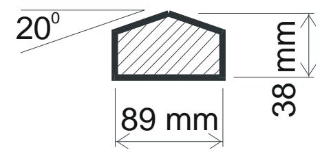
- Where a bottom rail is bevelled, the minimum sizes shown in Table 2.1.2. may be reduced to allow for a bevel, as detailed in Figure 2.1.2.
Figure 2.1.2. Bevel Detail
2.1.3. Floor Construction (See Appendix A.)
- The minimum dimensions of wood floor joists and wood decking shall conform to Table 2.1.3.
- Except as provided in Details EA-1 to ED-5, wood decking shall be fastened to each floor joist with nailing conforming to Table 2.1.3.
Table 2.1.3. Minimum Size of Floor Elements
| Floor Element | Minimum Size, mm (in) |
|---|---|
| Dimension Lumber Decking | 25 x 140 (5/4" x 6" nominal), when each plank is fastened with 2 - 63 mm (2½") nails |
| Dimension Lumber Decking | 38 x 89 (2" x 4" nominal), when each plank is fastened with 2 - 76 mm (3") nails |
| Dimension Lumber Joists | 38 x 184 (2" x 8" nominal) |
| Column 1 | 2 |
2.1.4. Connectors (See Appendix A.)
- Nails, screws, lag bolts and machine bolts shall not cause splitting of wood elements.
- Fasteners shall be resistant to corrosion.
- All nails shall be common spiral.
(See also A-2.1.4. in Appendix A for glued joints.)
2.1.5. Decay-Resistant Lumber (See Appendix A.)
- Lumber for guard systems and floor systems shall be
- a species resistant to decay,
- preservative treated to prevent decay, or
- pressure-treated.
- All cut ends of preservative treated lumber shall be treated to prevent decay.
2.2. Structural Details
2.2.1. Post and Rail System
- An exterior guard constructed as a Post and Rail System shall conform to the applicable connection details listed in Table 2.2.1.
2.2.2. Cantilevered Picket System
- An exterior guard constructed as a Cantilevered Picket System shall conform to the applicable connection details listed in Table 2.2.2.
Table 2.2.1. Exterior Post and Rail System Connection Details
| Connection Detail | Detail Number | Description |
|---|---|---|
| Top Rail to Post — and / or — Bottom Rail to Post | EA-1 | Top rail nailed to post |
| Top Rail to Post — and / or — Bottom Rail to Post | EA-2 | Top/bottom rail skew nailed to post with 76 mm (3") nails |
| Top Rail to Post — and / or — Bottom Rail to Post | EA-3 | Top/bottom rail skew nailed to post with 63 mm (21/2") nails |
| Top Rail to Post — and / or — Bottom Rail to Post | EA-4 | Top/bottom rail face nailed or screwed to post |
| Top Rail to Post — and / or — Bottom Rail to Post | EA-5 | Top/bottom rail fastened to post with framing anchors |
| Post to Floor | EB-1 | Post nailed to rim joist |
| Post to Floor | EB-2 | Post screwed to rim joist |
| Post to Floor | EB-3 | Post bolted to floor joist with 8 mm (5/16") machine bolts |
| Post to Floor | EB-4 | Post bolted to floor joist with 9.5 mm (3/8") machine bolts |
| Post to Floor | EB-5 | Post bolted to 2 floor joists |
| Post to Floor | EB-6 | Post fastened to floor, where guard is parallel to floor joists |
| Infill Picket | EC-1 | Picket nailed to endcap; endcap screwed to rail |
| Infill Picket | EC-2 | Picket nailed to rail |
| Infill Picket | EC-3 | Picket screwed to rail |
| Infill Picket | EC-4 | Picket screwed to top rail and rim joist |
| Column 1 | 2 | 3 |
Table 2.2.2. Exterior Cantilevered Picket System Connection Details
| Connection Detail | Detail Number | Description |
|---|---|---|
| Cantilevered Picket — (Douglas Fir-Larch, Spruce-Pine-Fir, Hem-Fir Species) | ED-1 | Picket screwed to rim joist |
| Cantilevered Picket — (Douglas Fir-Larch, Spruce-Pine-Fir, Hem-Fir Species) | ED-2 | Picket screwed to rim joist, where guard is parallel to floor joists |
| Cantilevered Picket — (Northern Species) | ED-3 | Picket screwed to rim joist and deck |
| Cantilevered Picket — (Northern Species) | ED-4 | Picket screwed to rim joist and deck, where guard is parallel to floor joists |
| Cantilevered Picket — (Douglas Fir-Larch, Spruce-Pine-Fir, Hem-Fir Species, Northern Species) | ED-5 | Corner |
| Column 1 | 2 | 3 |
Section 3 Interior Guards
3.1. Materials
3.1.1. Lumber and Wood Products
- Lumber species used for a primary loadbearing element in a guard shall be a species listed in the Table 3.1.2.
- Except as provided in Sentence (4), the minimum grade of softwood dimension lumber for posts, rails and joists shall be Northern Species, No. 2.
- Except as provided in Sentence (4), the minimum grade of softwood dimension lumber for cantilevered pickets shall be Northern Species, No. 2 Picket grade.
- White pine and hemlock lumber used for posts, rails and non-cantilevered pickets shall be clear straight grain material.
- Oak, maple and yellow poplar lumber used for posts, rails and pickets shall be clear straight grain material.
3.1.2. Lumber Dimensions
- The minimum sizes of loadbearing elements of wood guards shall conform to Table 3.1.2.
3.1.3. Floor Construction
- The minimum dimensions of wood floor joists and wood subflooring shall conform to Table 3.1.3. (See A-2.1.3. in Appendix A.)
3.1.4. Connectors
- Nails, screws, lag bolts and machine bolts shall not cause splitting of the wood elements. (See A-2.1.4. in Appendix A.) (See also A-2.1.4. in Appendix A for glued joints.)
3.2. Structural Details
3.2.1. Post and Rail System
- An interior guard constructed as a Post and Rail System shall conform to the applicable connection details listed in Table 3.2.1.
3.2.2. Cantilevered Picket System
- An interior guard constructed as a Cantilevered Picket System shall conform to the applicable connection details listed in Table 3.2.2.
3.2.3. Guards for Stairs
- An interior guard for a stair shall conform to the appropriate connection details listed in Table 3.2.3.
Table 3.1.2. Minimum Size of Loadbearing Elements
| Guard Element | Species | Minimum Size, mm (in) | Detail Number(1) |
|---|---|---|---|
| Post | Oak, Maple | 70 x 70 (23/4" x 23/4") Base, 45 (13/4") Turned Diameter | IB-1, IG-1, IG-2, IG-3 |
| Post | Hemlock, White Pine, Yellow Poplar | 82 x 82 (31/4" x 31/4") Base, 50 (2") Turned Diameter | IB-1, IG-1, IG-2, IG-3 |
| Post in a Volute | Oak, Maple | 70 x 70 (23/4" x 23/4") Base, 50 (2") Turned Diameter | IG-4 |
| Top Rail | Oak, Maple | 41 x 67 (15/8" x 25/8") | IA-1, IF-1 |
| Bottom Rail | Oak, Maple | 41 x 67 (15/8" x 25/8") 19 x 67 (3/4" x 25/8"), if continuously supported | IA-1, IF-1 |
| Infill Picket | Oak, Maple | 20 (3/4") Diameter | IC-1, IC-2 |
| Infill Picket | Yellow Poplar | 22 (7/8") Diameter | IC-1, IC-2 |
| Infill Picket | White Pine, Hemlock | 24 (31/32") Diameter | IC-1, IC-2 |
| Picket in a Volute | Oak, Maple | 32 x 32 (19/32" x 19/32") Base, 20 (3/4") Turned Diameter | IG-4 |
| Picket in a Volute | Yellow Poplar | 45 x 45 (13/4" x 13/4") Base, 22 (7/8") Turned Diameter | IG-5, IG-6 |
| Picket in a Volute | White Pine, Hemlock | 45 x 45 (13/4" x 13/4") Base, 24 (31/32") Turned Diameter | IG-5, IG-6 |
| Cantilevered Picket | Northern Species, Douglas Fir-Larch, Spruce-Pine-Fir, Hem-Fir, Hardwood | 32 x 32 (19/32" x 19/32") | IE-1, IH-1 |
| Column 1 | 2 | 3 | 4 |
Notes to Table 3.1.2.:
1. This column lists details that incorporate the guard elements specified in this Table. ↑
Table 3.1.3. Minimum Size of Floor Elements
| Floor Element | Minimum Size, mm (in) |
|---|---|
| Subfloor | 15.5 (5/8") plywood or equivalent |
| Dimension Lumber Joists | 38 x 184 (2" x 8" nominal) |
| Column 1 | 2 |
Table 3.2.1. Interior Post and Rail System Connection Details
| Connection Detail | Detail Number | Description |
|---|---|---|
| Top and/or Bottom Rail to Post | IA-1 | Rail glued and screwed to post |
| Post to Floor | IB-1 | Notched post glued and bolted to rim joist |
| Infill Picket | IC-1 | Picket set into rails |
| Infill Picket | IC-2 | Picket dowelled into rails |
| Stud Wall | ID-1 | Wood stud and gypsum board |
| Column 1 | 2 | 3 |
Table 3.2.2. Interior Cantilevered Picket System Connection Details
| Connection Detail | Detail Number | Description |
|---|---|---|
| Picket to Floor | IE-1 | Picket screwed to rim joist |
| Column 1 | 2 | 3 |
Table 3.2.3. Interior Stair Guard Connection Details
| Connection Detail | Detail Number | Description |
|---|---|---|
| Rail to Post | IF-1 | Top or bottom rail glued and screwed to post |
| Post to Floor — and/or — Picket Volute to Floor | IG-1 | Notched post glued and screwed to stringer and riser |
| Post to Floor — and/or — Picket Volute to Floor | IG-2 | Post glued and screwed to stringer |
| Post to Floor — and/or — Picket Volute to Floor | IG-3 | Post glued and screwed to stringer and stud wall |
| Post to Floor — and/or — Picket Volute to Floor | IG-4 | Post and picket volute, oak or maple |
| Post to Floor — and/or — Picket Volute to Floor | IG-5 | Picket volute, 260 mm (101/4") wide |
| Post to Floor — and/or — Picket Volute to Floor | IG-6 | Picket volute, 240 mm (91/2") wide |
| Infill Picket | IC-1 or IC-2 | Detail IC-1 or IC-2 in Table 3.2.1., modified to suit a sloping installation, may be used. |
| Cantilevered Picket | IH-1 | Picket screwed to stair stringer |
| Column 1 | 2 | 3 |
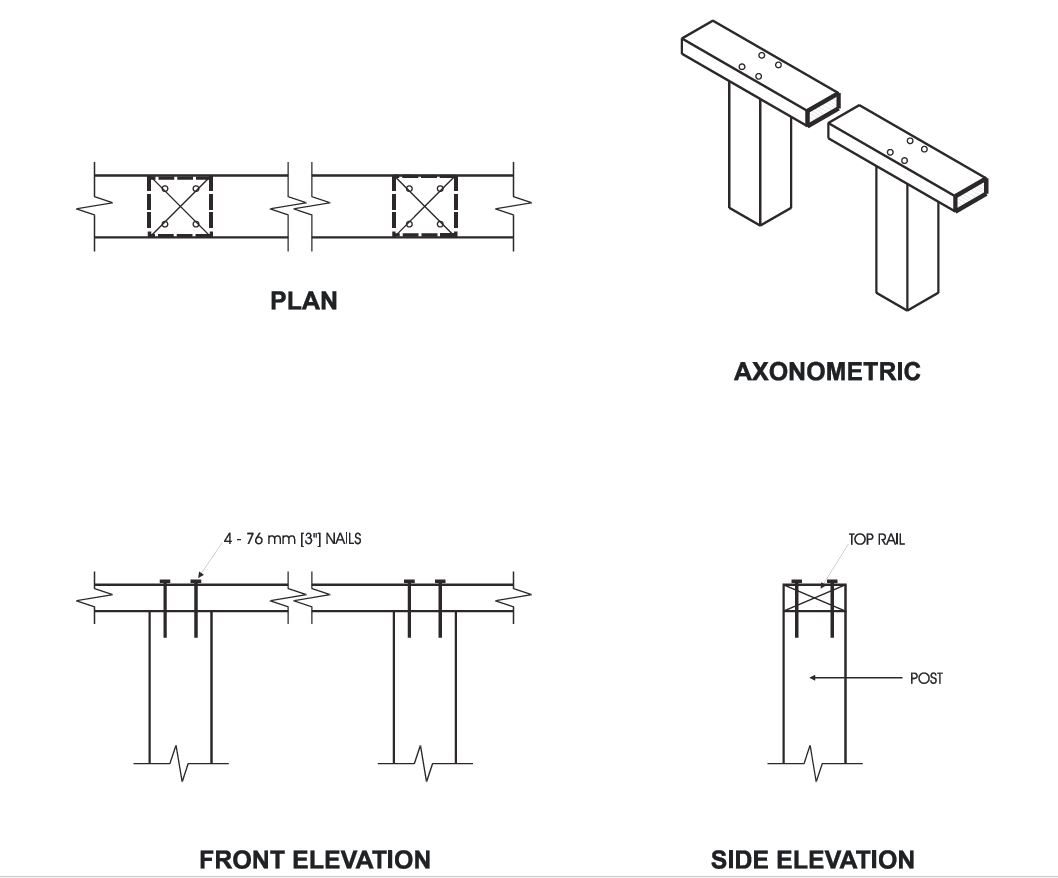
Detail EA-1 — Exterior Connection: Top Rail Nailed to Post
Notes:
- The top rail must be continuous. Use Detail EA-5 at the end spans, where continuity ends.
Maximum Span of Rail Between Posts
| Species | Maximum Span, m (ft-in) |
|---|---|
| Douglas Fir-Larch, Hem-Fir, Spruce-Pine-Fir | 1.52 (5'-0") |
| Northern Species | 1.52 (5'-0") |
| Column 1 | 2 |
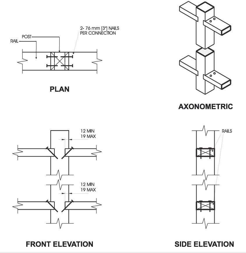
Detail EA-2 — Exterior Connection: Top/Bottom Rail Skew Nailed to Post - 76 mm (3") Nails
Notes:
- The maximum span is more often governed by post spacing.
- Provide support to bottom rail at intervals not more than 2.0 m (6'-7").
- The bottom rail may be bevelled as detailed in Figure 2.1.2.
- Dimensions shown are in mm unless otherwise specified.
Maximum Span of Rail Between Posts
| Species | Maximum Span, m (ft-in) |
|---|---|
| Douglas Fir-Larch, Hem-Fir, Spruce-Pine-Fir | 2.72 (8'-11") |
| Northern Species | 2.18 (7'-2") |
| Column 1 | 2 |
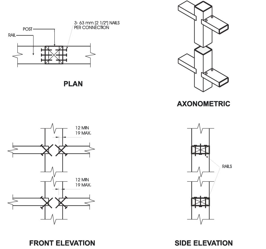
Detail EA-3 — Exterior Connection: Top/Bottom Rail Skew Nailed to Post - 63 mm (2½") Nails
Notes:
- Provide support to bottom rail at intervals not more than 2.0 m (6'-7").
- The bottom rail may be bevelled as detailed in Figure 2.1.2.
- Dimensions shown are in mm unless otherwise specified.
Maximum Span of Rail Between Posts
| Species | Maximum Span, m (ft-in) |
|---|---|
| Douglas Fir-Larch, Hem-Fir, Spruce-Pine-Fir | 2.72 (8'-11") |
| Northern Species | 2.18 (7'-2") |
| Column 1 | 2 |
Detail EA-4 — Exterior Connection: Top/Bottom Rail Face Nailed or Screwed to Post
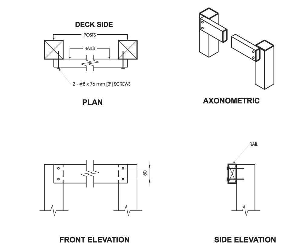
Notes:
- If the rails are located on the deck side of the posts, 76 mm (3") nails may be used in place of the screws.
- Where the top rail is continuous, the top rail may be fastened to each post with 3 - #8 x 76 mm (3") screws.
- Dimensions shown are in mm unless otherwise specified.
Maximum Span of Rail Between Posts
| Species | Maximum Span, m (ft-in) |
|---|---|
| Douglas Fir-Larch, Hem-Fir, Spruce-Pine-Fir | 1.77 (5'-10") |
| Northern Species | 1.41 (4'-8") |
| Column 1 | 2 |
Detail EA-5 — Exterior Connection: Top/Bottom Rail Fastened to Post with Framing Anchors
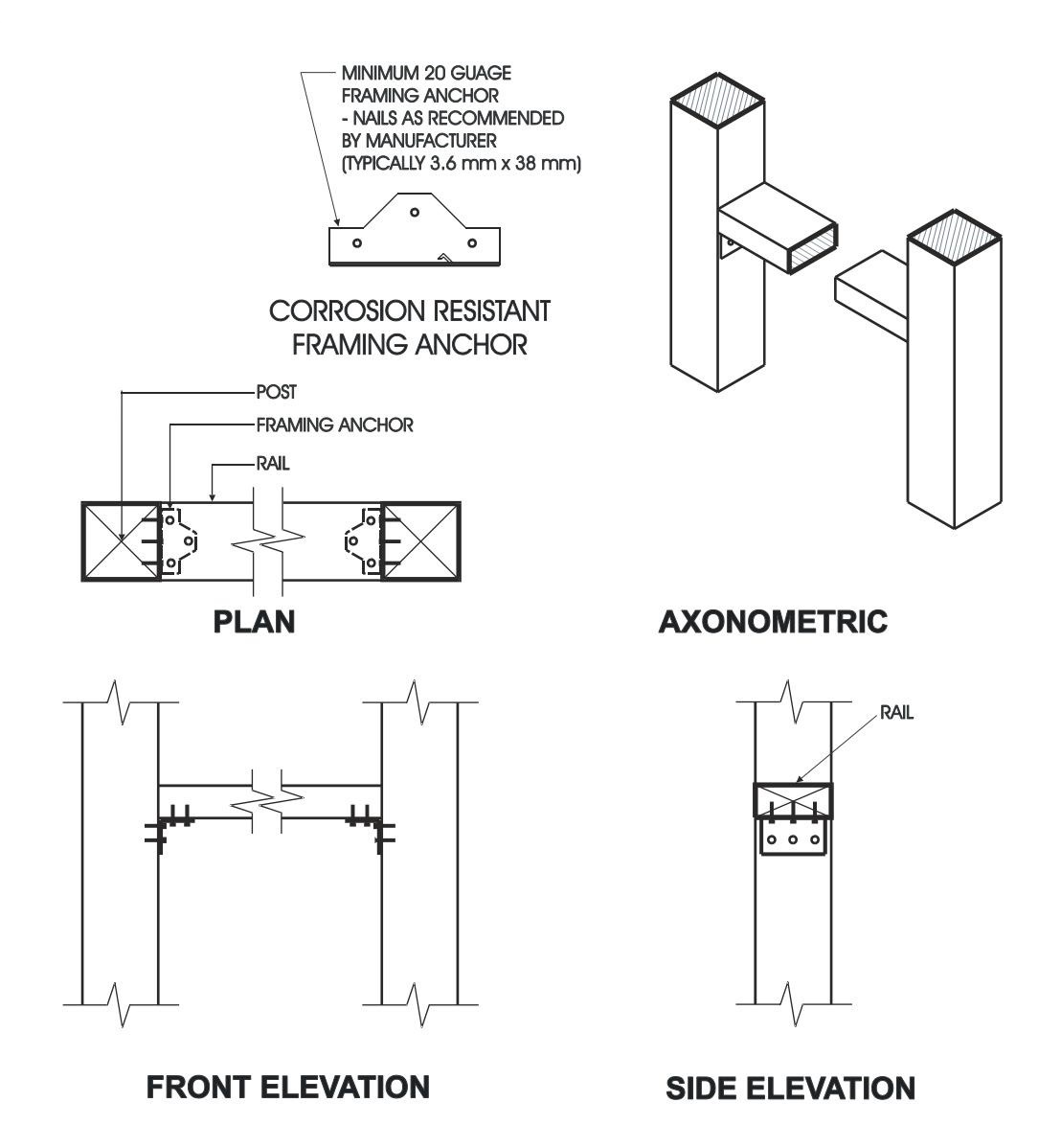
Notes:
- Provide support to bottom rail at intervals not more than 2.0 m (6'-7").
- The bottom rail may be bevelled as detailed in Figure 2.1.2.
- Dimensions shown are in mm unless otherwise specified.
Maximum Span of Rail Between Posts
| Species | Maximum Span, m (ft-in) |
|---|---|
| Douglas Fir-Larch, Hem-Fir, Spruce-Pine-Fir | 2.72 (8'-11") |
| Northern Species | 2.18 (7'-2") |
| Column 1 | 2 |
Detail EB-1 — Exterior Connection: Post Nailed to Rim Joist
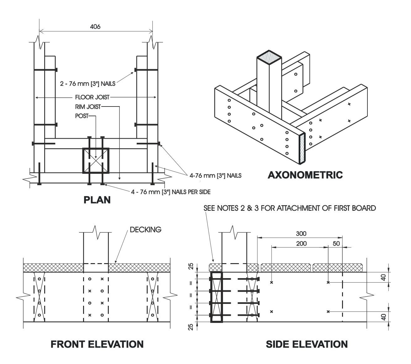
Notes:
- Decking is omitted from the plan view and the axonometric view for clarity.
- Fasten 25 mm x 140 mm (5/4" x 6" nominal) outer deck board to rim joist with 63 mm (2½") nails at 300 mm (12").
- Fasten 25 mm x 140 mm (5/4" x 6" nominal) outer deck board to floor joist with 1 - 63 mm (2½") nail at each joist.
- The post may be positioned anywhere between the joists.
- Dimensions shown are in mm unless otherwise specified.
Maximum Span of Rail Between Posts
| Species | Maximum Span, m (ft-in) |
|---|---|
| Douglas Fir-Larch, Hem-Fir, Spruce-Pine-Fir | 1.22 (4'-0") |
| Northern Species | 1.20 (3'-11") |
| Column 1 | 2 |
Detail EB-2 — Exterior Connection: Post Screwed to Rim Joist
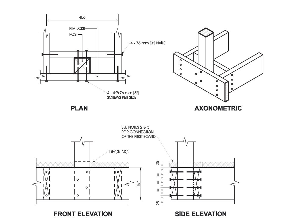
Notes:
- Decking is omitted from the plan view and the axonometric view for clarity.
- Fasten 25 mm x 140 mm (5/4" x 6" nominal) outer deck board to rim joist with 63 mm (2½") nails at 300 mm (12").
- Fasten 25 mm x 140 mm (5/4" x 6" nominal) outer deck board to floor joist with 1 - 63 mm (2½") nail at each joist.
- The post may be positioned anywhere between the joists.
- #9 screws may be replaced by #8 screws if the maximum spacing between posts is not more than 1.20 m (3'-11").
- Dimensions shown are in mm unless otherwise specified.
Maximum Span of Rail Between Posts
| Species | Maximum Span, m (ft-in) |
|---|---|
| Douglas Fir-Larch, Hem-Fir, Spruce-Pine-Fir | 1.56 (5'-1") |
| Northern Species | 1.20 (3'-11") |
| Column 1 | 2 |
Detail EB-3 — Exterior Connection: Post Bolted to Floor Joist - 8 mm (5/16") Bolts
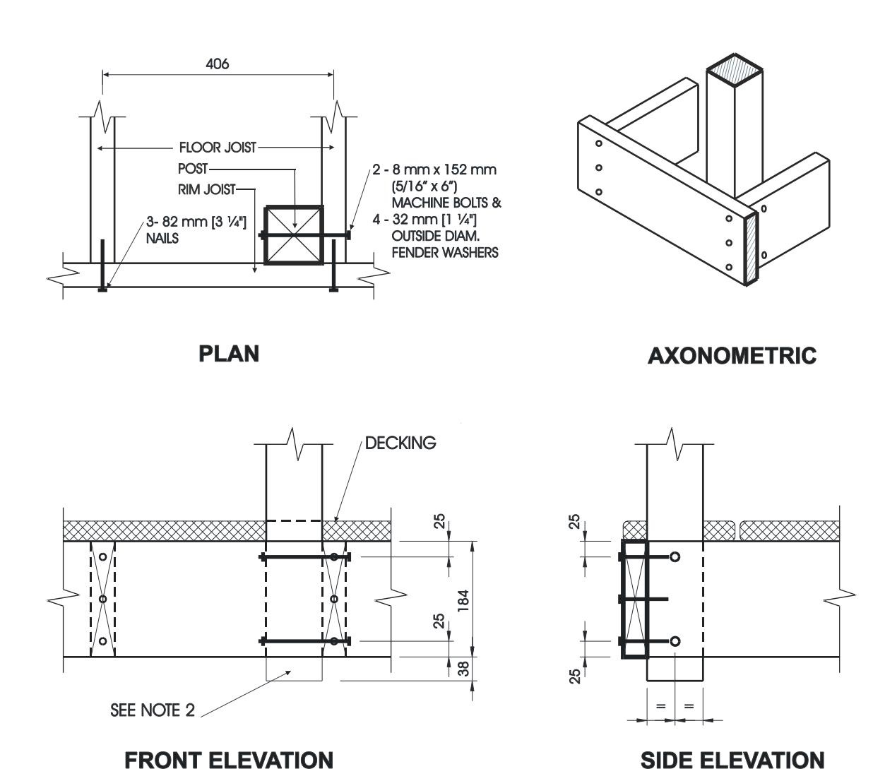
Notes:
- Decking is omitted from the plan view and the axonometric view for clarity.
- 38 mm (1½") post projection is not required where the maximum spacing between posts does not exceed 1.20 m (3'-11").
- Joists may be spaced at 610 mm (24") o.c. or 406 mm (16") o.c.
- Where floor joists are spaced at 610 mm (24") o.c., decking shall have a minimum thickness of 38 mm (1½") and shall be fastened to the floor with 2 - 76 mm (3") nails.
- Dimensions shown are in mm unless otherwise specified.
Maximum Spacing Between Posts
| Species | Maximum Span, m (ft-in) |
|---|---|
| Douglas Fir-Larch, Hem-Fir, Spruce-Pine-Fir | 1.29 (4'-3") |
| Northern Species | 1.20 (3'-11") |
| Column 1 | 2 |
Detail EB-4 — Exterior Connection: Post Bolted to Floor Joist - 9.5 mm (3/8") Bolts
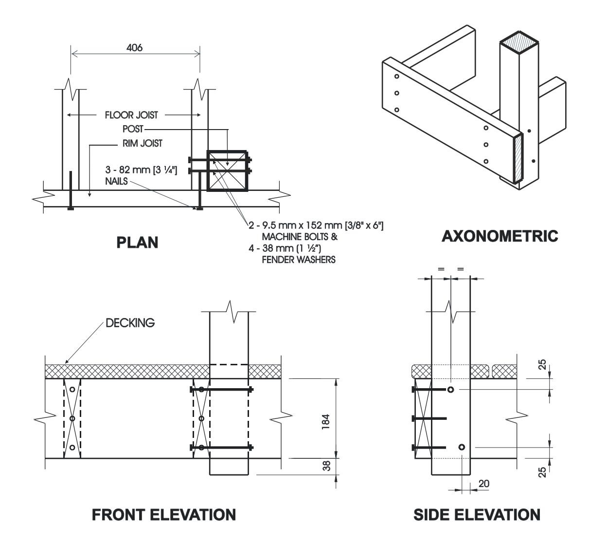
Notes:
- Decking is omitted from the plan view and the axonometric view for clarity.
- 38 mm (1½") post projection is not required where the maximum spacing between posts does not exceed 1.20 m (3'-11").
- Joists may be spaced at 610 mm (24") o.c. or 406 mm (16") o.c.
- Where floor joists are spaced at 610 mm (24") o.c., decking shall have a minimum thickness of 38 mm (1½") and shall be fastened to the floor with 2 - 76 mm (3") nails.
- Dimensions shown are in mm unless otherwise specified.
Maximum Spacing Between Posts
| Species | Maximum Span, m (ft-in) |
|---|---|
| Douglas Fir-Larch, Hem-Fir, Spruce-Pine-Fir | 1.49 (4'-11") |
| Northern Species | 1.20 (3'-11") |
| Column 1 | 2 |
Detail EB-5 — Exterior Connection: Post Bolted to 2 Floor Joists
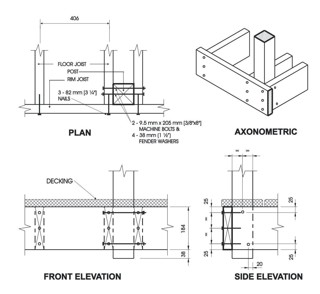
Notes:
- Decking is omitted from the plan view and the axonometric view for clarity.
- 38 mm (1½") post projection is not required where the maximum spacing between posts does not exceed 1.20 m (3'-11").
- Joists may be spaced at 610 mm (24") o.c. or 406 mm (16") o.c.
- Where floor joists are spaced at 610 mm (24") o.c., decking shall have a minimum thickness of 38 mm (1½") and shall be fastened to the floor with 2 - 76 mm (3") nails.
- Dimensions shown are in mm unless otherwise specified.
Maximum Spacing Between Posts
| Species | Maximum Span, m (ft-in) |
|---|---|
| Douglas Fir-Larch, Hem-Fir, Spruce-Pine-Fir | 2.14 (7'-0") |
| Northern Species | 1.20 (3'-11") |
| Column 1 | 2 |
Detail EB-6 — Exterior Connection: Post Fastened to Floor, Guard Parallel to Floor Joists
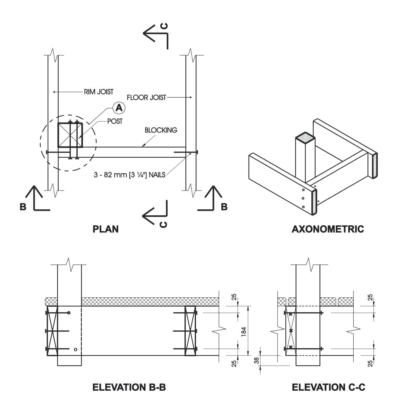
Notes:
- Use any of the connection details shown on Details EB-1 to EB-5 at location “A”. Connection Detail EB-4 is shown in this detail, as an example.
- Maximum spacing between posts is determined from connection detail used at location “A”.
- Decking is omitted from the plan view and the axonometric view for clarity.
- Blocking shall be not less than 38 mm x 184 mm (2" x 8" nominal).
- Dimensions shown are in mm unless otherwise specified.
Detail EC-1 — Exterior Connection: Infill Picket Nailed to Endcap - Endcap Screwed to Rail
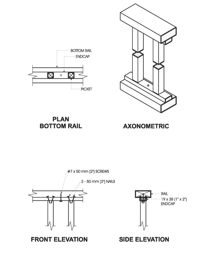
Notes:
- Fasten each end of each picket to endcaps with 2 - 50 mm (2") nails.
- Fasten endcaps to rails with #7 x 50 mm (2") screws at 300 mm (12") o.c.
- See Table 2.1.2. for minimum sizes of pickets.
Detail EC-2 — Exterior Connection: Infill Picket Nailed to Rail
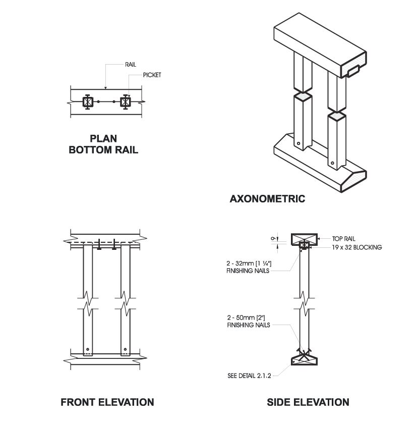
Notes:
- See Table 2.1.2. for minimum sizes of pickets.
- Dimensions shown are in mm unless otherwise specified.
Detail EC-3 — Exterior Connection: Infill Picket Screwed to Rail
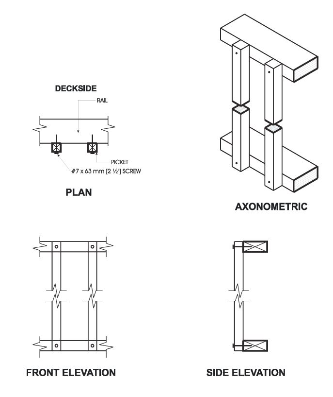
Detail EC-4 — Exterior Connection: Infill Picket Screwed to Top Rail and Rim Joist
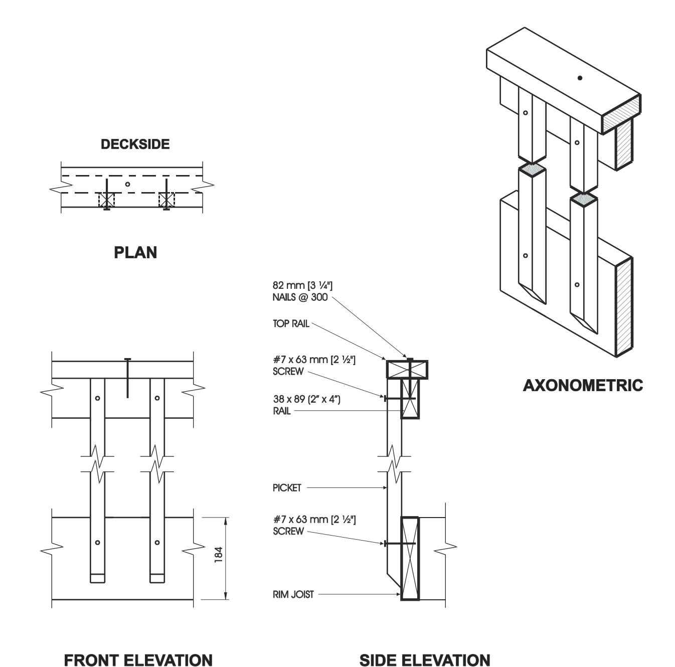
Note:
- Dimensions shown are in mm unless otherwise specified.
Detail ED-1 — Exterior Connection: Cantilevered Picket Screwed to Rim Joist
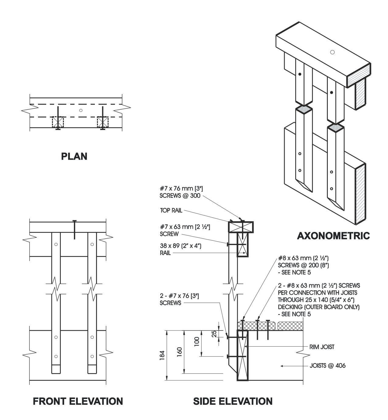
Notes:
- Provide a suitable post, return, or solid support at each end of the guard.
- Wood for cantilevered pickets shall be Douglas Fir-Larch, Spruce-Pine-Fir, or Hem-Fir Species.
- Fasten rim joist to each floor joist with 3 - 82 mm (3¼") nails.
- Dimensions shown are in mm unless otherwise specified.
- The outer deck board shall not be less than 140 mm (6" nominal) wide. Where 38 mm (2" nominal) thick boards are used, the length of the wood screws shall be not less than 76 mm (3").
Detail ED-2 — Exterior Connection: Cantilevered Picket Screwed to Rim Joist, Guard Parallel to Floor Joists
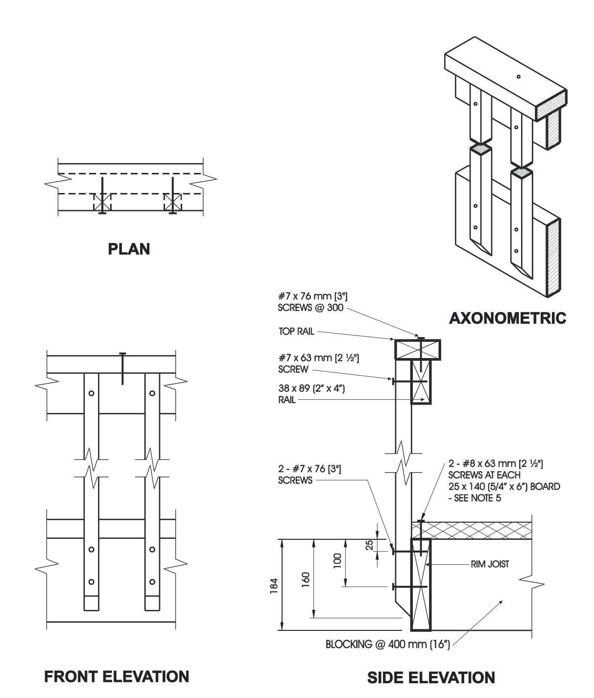
Notes:
- Provide a suitable post, return, or solid support at each end of the guard.
- Wood for cantilevered pickets shall be Douglas Fir-Larch, Spruce-Pine-Fir, or Hem-Fir Species.
- Fasten rim joist to blocking with 3 - 82 mm (3¼") nails.
- Dimensions shown are in mm unless otherwise specified.
- Where 38 mm (2" nominal) thick boards are used, the length of the wood screws shall be not less than 76 mm (3").
Detail ED-3 — Exterior Connection: Cantilevered Picket Screwed to Rim Joist and Deck
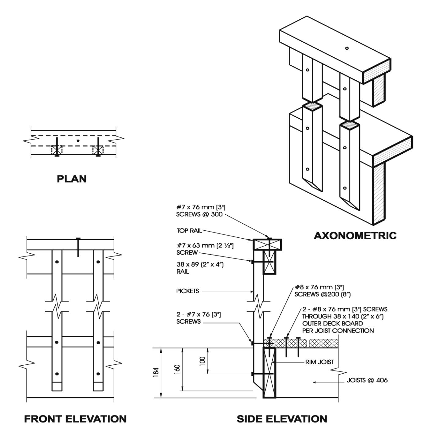
Notes:
- Provide a suitable post, return, or solid support at each end of the guard.
- Wood for cantilevered pickets shall be Northern Species.
- Fasten rim joist to each floor joist with 3 - 82 mm (3¼") nails.
- Dimensions shown are in mm unless otherwise specified.
Detail ED-4 — Exterior Connection: Cantilevered Picket Screwed to Rim Joist and Deck, Guard Parallel to Floor Joists
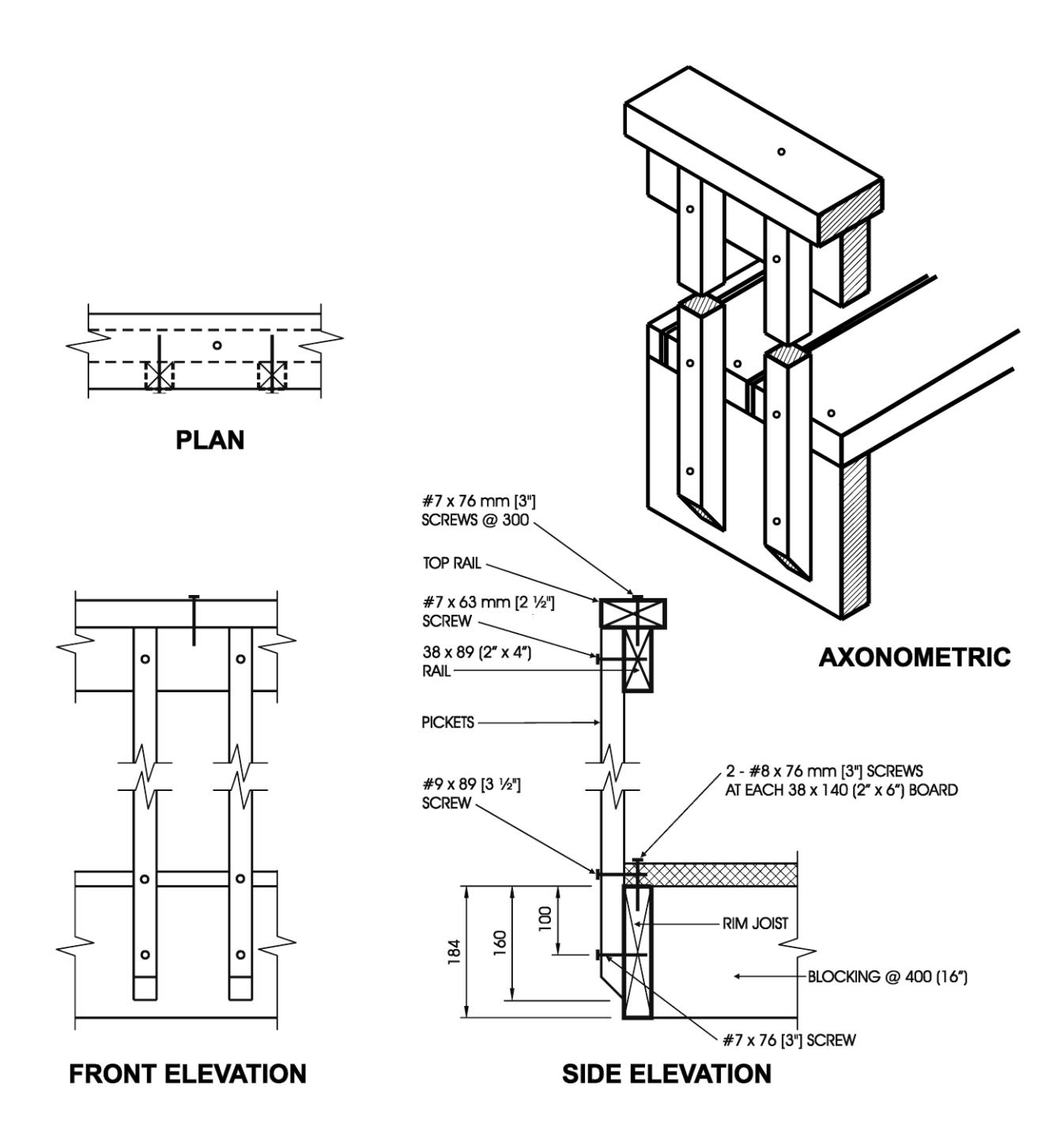
Notes:
- Provide a suitable post, return, or solid support at each end of the guard.
- Wood for cantilevered pickets shall be Northern Species.
- Fasten rim joist to blocking with 3 - 82 mm (3¼") nails.
- Dimensions shown are in mm unless otherwise specified.
Detail ED-5 — Exterior Connection: Corner Joint
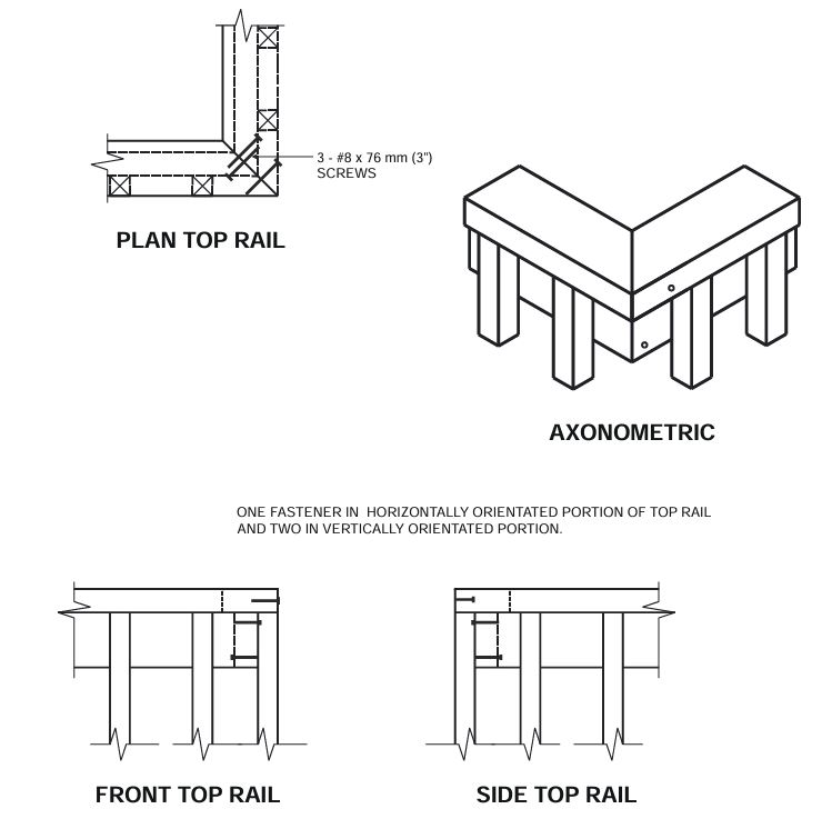
Notes:
- Screws fastening pickets are omitted for clarity.
- Provide a minimum of 10 pickets beyond the return if end restraint of the guard is provided by this return detail only.
Detail IA-1 — Interior Connection: Rail Glued and Screwed to Post
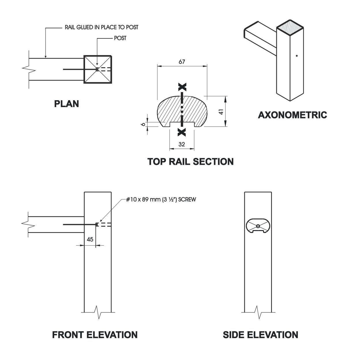
Notes:
- Other top rail systems may be used provided the section modulus is not less than 24,000 mm3, measured about the x-x axis.
- Pickets omitted on drawing for clarity.
- Connection details for fastening of pickets to rails are shown on Details IC-1 and IC-2.
- Dimensions shown are in mm unless otherwise specified.
Maximum Span of Rail Between Posts
| Species | Maximum Span, m (ft-in) |
|---|---|
| Oak, Maple | 3.30 (10'-10") |
| Column 1 | 2 |
Detail IB-1 — Interior Connection: Notched Post Glued and Bolted to Rim Joist
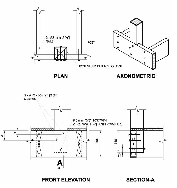
Notes:
- Minimum dimension of post is 82 mm x 82 mm (3¼" x 3¼").
- Notch post 38 mm x 152 mm (1½" x 6") at rim joist.
- Dimensions shown are in mm unless otherwise specified.
Maximum Spacing Between Posts
| Post Species | Maximum Span, m (ft-in) |
|---|---|
| Oak, Maple, Yellow Poplar, Hemlock, White Pine | 3.30 (10'-10") |
| Column 1 | 2 |
Detail IC-1 — Interior Connection: Infill Picket Set into Rails
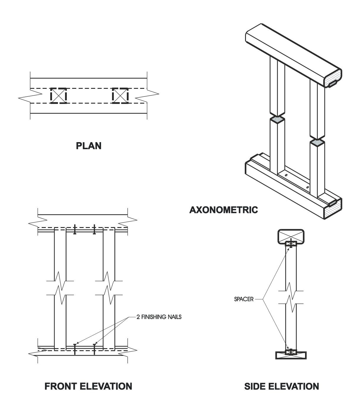
Notes:
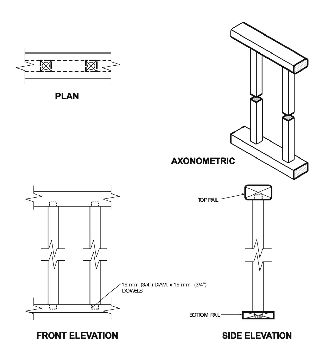
- See Table 3.1.2. for minimum sizes of pickets.
- For top and bottom rail provide 6 mm (1/4") deep rabbet.
Detail IC-2 — Interior Connection: Infill Picket Dowelled into Rails
Notes:
- See Table 3.1.2 for minimum sizes of pickets.
- Pickets dowelled 19 mm (3/4") deep into rails with 19 mm (3/4") diameter dowels.
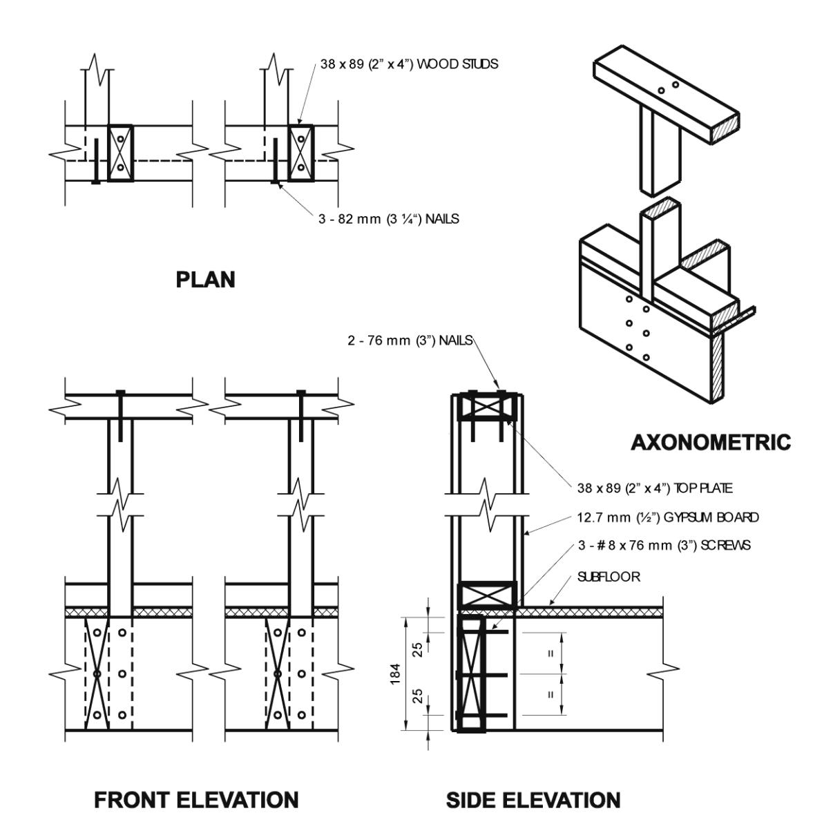
Detail ID-1 — Interior Connection: Wood Stud and Gypsum Board Guard
Notes:
- Fasten plywood subfloor to joists with 50 mm (2") nails at 150 mm (6") oc along edges and at 300 mm (12") oc along intermediate supports.
- Gypsum board omitted on plan, front elevation, and axonometric for clarity.
- Dimensions shown are in mm unless otherwise specified.
- Provide a suitable post, return, or solid support at each end of the guard.
Maximum Spacing Between Wood Studs
| Stud Species | Maximum Spacing, mm (in) |
|---|---|
| Douglas Fir-Larch, Hem-Fir, Spruce-Pine-Fir, Northern Species | 406 (16") |
| Column 1 | 2 |
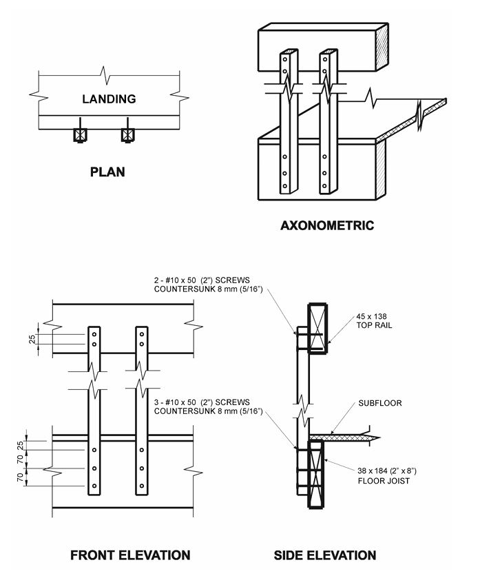
Detail IE-1 — Interior Connection: Cantilevered Picket Screwed to Rim Joist
Notes:
- Provide a suitable post, return, or solid support at each end of the guard.
- See Table 3.1.2. for minimum sizes of pickets.
- Dimensions shown are in mm unless otherwise specified.
- Rim joist and top rail of oak or maple.
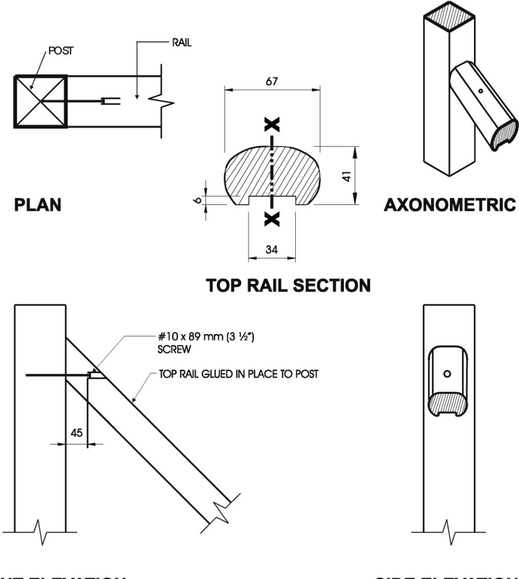
Detail IF-1 — Interior Stair Guard Connection: Top/Bottom Rail Glued and Screwed to Post
Notes:
- Maximum permitted span is based on a slope between 35° and 45° from the horizontal.
- Minimum section modulus of top rail shall be 24,000 mm3, measured about the x-x axis.
- Pickets omitted on drawing, for clarity.
- Detail IC-1 or Detail IC-2, modified to suit a sloping application may be used for picket to rail connections.
Maximum Span of Rail, Measured Along the Slope
| Rail Species | Maximum Span, m (ft-in) |
|---|---|
| Oak, Maple | 4.30 (14'-1") |
| Column 1 | 2 |
Detail IG-1 — Interior Stair Guard Connection: Notched Post Glued & Screwed to Stringer & Riser
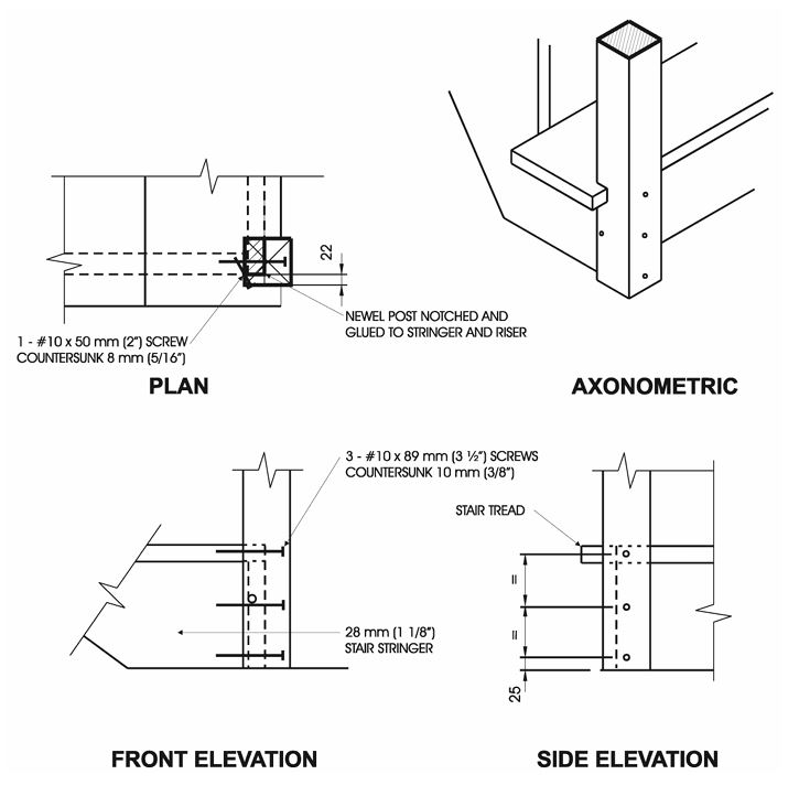
Notes:
- Stringer shall be oak or maple.
- Notch post 38 mm x 60 mm (1½" x 2⅜") to fit over stair stringer.
- Only the first riser and tread are shown, for clarity.
- Minimum thickness of riser shall be 12 mm (1/2").
- Detail IC-1 or Detail IC-2, modified to suit a sloping application may be used for picket to rail connections.
- Dimensions shown are in mm unless otherwise specified.
Maximum Spacing Between Posts
| Post Species | Maximum Span, m (ft-in) |
|---|---|
| Oak, Maple, Yellow Poplar, Hemlock, White Pine | 3.30 (10'-10") |
| Column 1 | 2 |
Detail IG-2 — Interior Stair Guard Connection: Post Glued and Screwed to Stringer
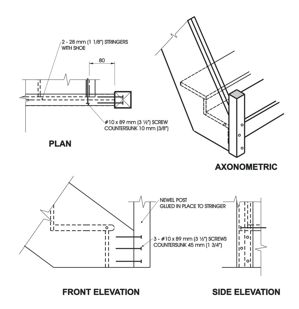
Notes:
- Stringer shall be oak or maple.
- Only the first riser and tread are shown, for clarity.
- Minimum thickness of riser shall be 12 mm (1/2").
- Detail IC-1 or Detail IC-2, modified to suit a sloping application may be used for picket to rail connections.
- Dimensions shown are in mm unless otherwise specified.
Maximum Spacing Between Posts
| Post Species | Maximum Span, m (ft-in) |
|---|---|
| Oak, Maple, Yellow Poplar, Hemlock, White Pine | 3.30 (10'-10") |
| Column 1 | 2 |
Detail IG-3 — Interior Stair Guard Connection: Post Glued and Screwed to Stringer and Stud Wall
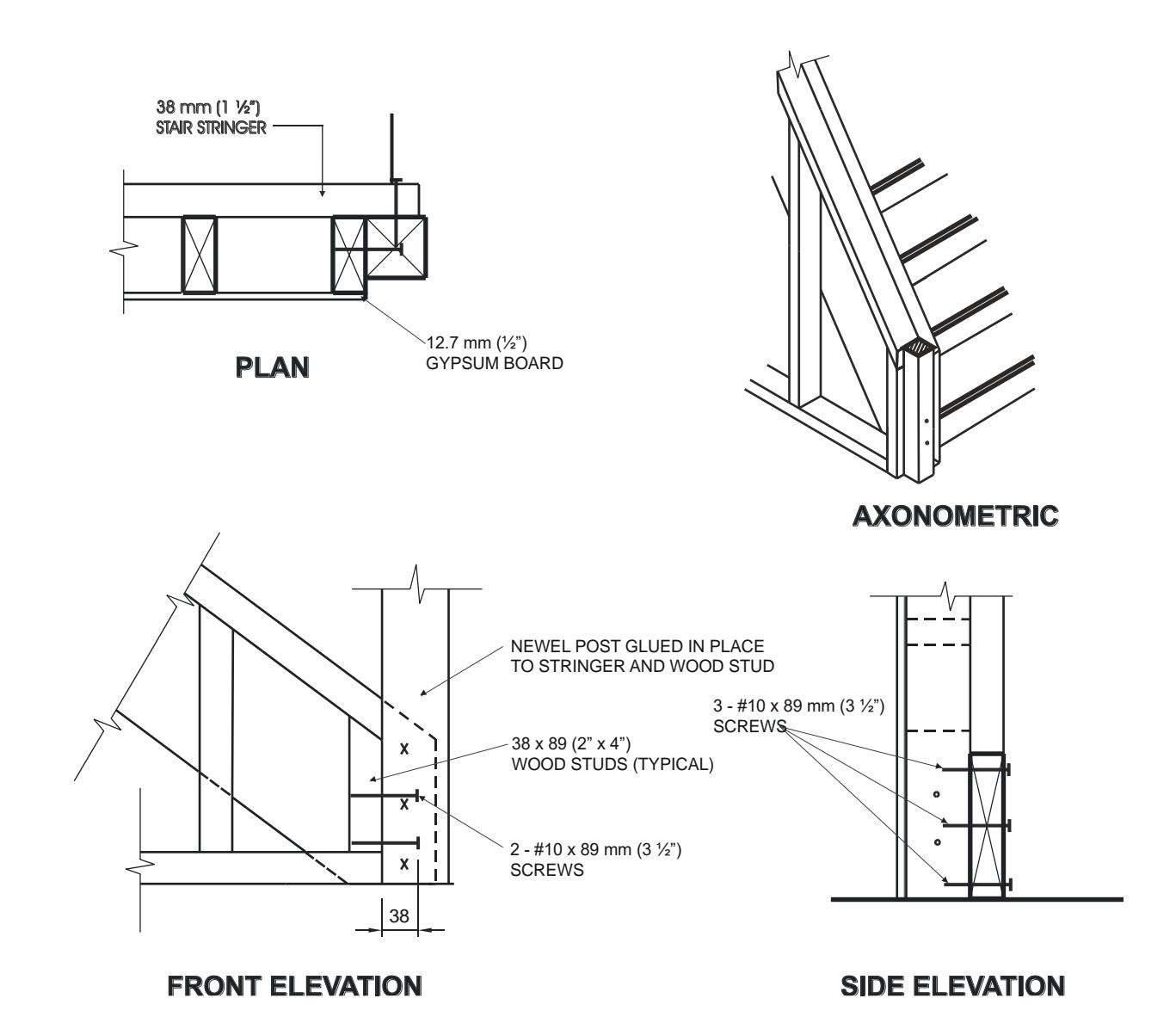
Notes:
- Minimum thickness of riser shall be 12 mm (½").
- Detail IC-1 or Detail IC-2, modified to suit a sloping application may be used for picket to rail connections.
- Dimensions shown are in mm unless otherwise specified.
Maximum Spacing Between Posts
| Post Species | Maximum Span, m (ft-in) |
|---|---|
| Oak, Maple, Yellow Poplar, Hemlock, White Pine | 3.30 (10'-10") |
| Column 1 | 2 |
Detail IG-4 — Interior Stair Guard Connection: Oak or Maple Post and Picket Volute
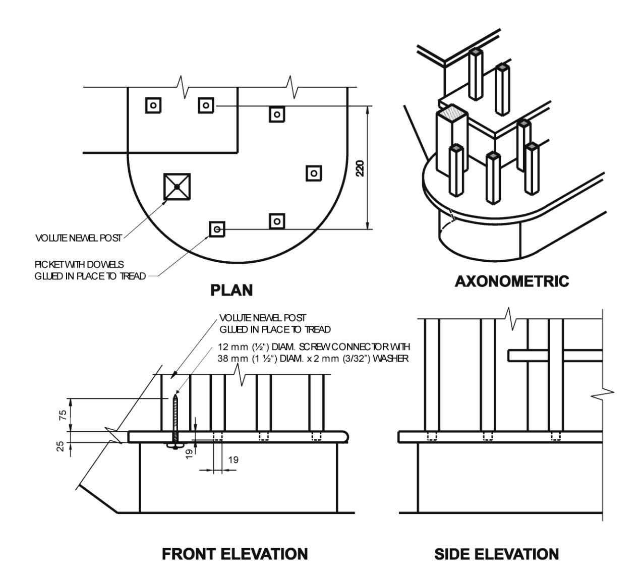
Notes:
- Maximum permitted span is measured from the centre of the volute to a post or other solid support.
- Other top rail systems may be used provided that the section modulus is not less than 24,000 mm3, measured about the vertical axis.
- Newel post and pickets in the volute shall be oak or maple. See Table 3.1.2. for minimum sizes of pickets.
- Detail IC-1 or Detail IC-2, modified to suit a sloping application may be used for picket to rail connections.
- Dimensions shown are in mm unless otherwise specified.
Maximum Span of Rail, Measured Along the Slope
| Post and Picket Species | Maximum Span, m (ft-in) |
|---|---|
| Oak, Maple | 4.30 (14'-1") |
| Column 1 | 2 |
Detail IG-5 — Interior Stair Guard Connection: Picket Volute, 260 mm (101/4") Wide
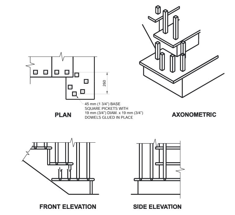
Notes:
- Maximum permitted span is measured from the centre of the volute to a post or other solid support.
- Other top rail systems may be used provided that the section modulus is not less than 24,000 mm3, measured about the vertical axis.
- See Table 3.1.2. for minimum sizes of pickets.
- Detail IC-1 or Detail IC-2, modified to suit a sloping application may be used for picket to rail connections.
- Dimensions shown are in mm unless otherwise specified.
Maximum Span of Rail
| Picket Species | Maximum Span, m (ft-in) |
|---|---|
| Yellow Poplar, Hemlock, White Pine | 1.80 (5'-11") |
| Column 1 | 2 |
Detail IG-6 — Interior Stair Guard Connection: Picket Volute, 240 mm (91/2") Wide
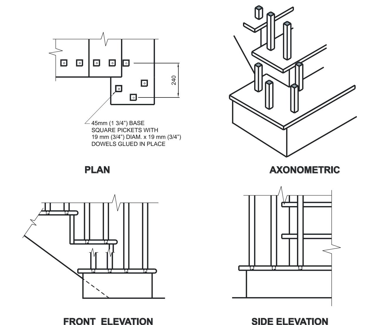
Notes:
- Maximum permitted span is measured from the centre of the volute to a post or other solid support.
- Other top rail systems may be used provided that the section modulus is not less than 24,000 mm3, measured about the vertical axis.
- See Table 3.1.2. for minimum sizes of pickets.
- Detail IC-1 or Detail IC-2, modified to suit a sloping application may be used for picket to rail connections.
- Dimensions shown are in mm unless otherwise specified.
Maximum Span of Rail
| Species | Maximum Span, m (ft-in) |
|---|---|
| Yellow Poplar, Hemlock, White Pine | 1.80 (5'-11") |
| Column 1 | 2 |
Detail IH-1 — Interior Stair Guard Connection: Cantilevered Picket Screwed to Stair Stringer
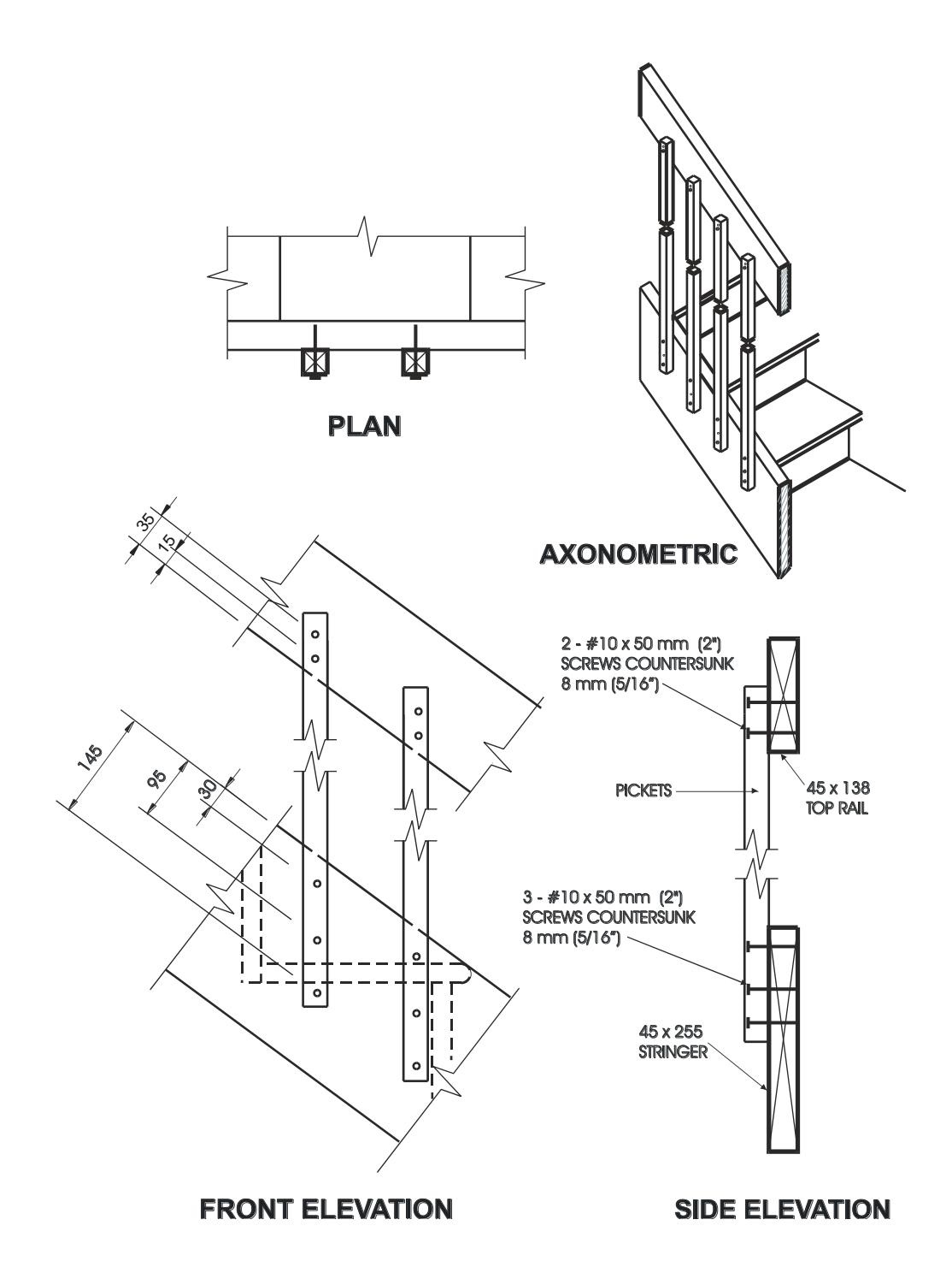
Notes:
- Stair stringer shall be oak or maple.
- Provide a suitable post, return, or solid support at each end of the guard.
- See Table 3.1.2. for minimum sizes of pickets.
- Dimensions shown are in mm unless otherwise specified.
Appendix A
Explanatory Material for SB-7
Appendix A to this Supplementary Standard is included for explanatory purposes only and does not form part of the requirements. The bold-faced reference numbers that introduce each item apply to the requirements in this Supplementary Standard.
A-1.1.1 Scope. A guard constructed in conformance with this Supplementary Standard is deemed to satisfy the requirements of Sentence 9.8.8.2.(6) of Division B.
Guard design in this Supplementary Standard is based on a height of 1,070 mm and a maximum clear spacing of 100 mm between pickets or balusters.
A-1.1.1.(2) Guards located on the exterior of a building are subject to deterioration as a result of hygrothermal, electrochemical or biochemical action.
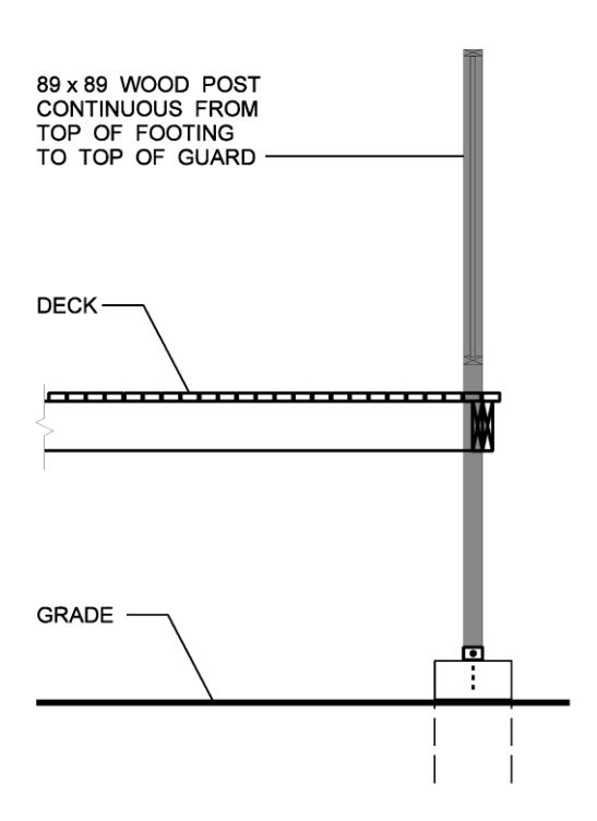
A-1.2.1 Cantilever Action.Where guards incorporate wood posts that are continuous from the top of the guard to the ground, or where the tops of the posts are attached to a superstructure that is connected to the building, the cantilever assumption in the Supplementary Standards is no longer valid. An example of a continuous post is shown in Figure A-1.2.1.
Figure A-1.2.1. Typical Continuous Post
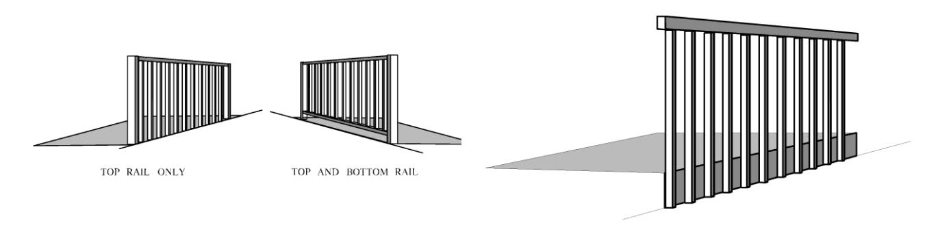
A-1.2.2. Classification. A Post and Rail System consists of a top rail that transfers horizontal loads to posts. The posts transfer the loads from the rail to the floor system. This system may incorporate a bottom rail that is anchored at each end to the posts. Infill panels or infill pickets are installed between the top rail and the floor or bottom rail. Examples of Post and Rail Systems are shown in Figure A-1.2.2.A.
The term “infill pickets” refers to an assembly of vertically oriented elements that span between the floor or bottom rail and the top rail. For the purpose of this Supplementary Standard, the words “picket” and “baluster” both relate to these individual elements.
The spacing of the posts in a Post and Rail System is detailed in this Supplementary Standard and is dictated by the ability of the posts to accept the design loads. The maximum spanning capacity of the rails is often not realised because it is dictated by the post spacing.
A Cantilevered Picket System consists of a top rail that transfers horizontal loads to pickets. The pickets transfer the loads from the top rail to the floor system. An example of a Cantilevered Picket System is shown in Figure A-1.2.2.B.
A guard classified as a Post and Rail System or a Cantilevered Picket System need not always terminate at a post if:
- the top rail is connected adequately to an element capable if accepting the forces applied to it, or
- the guard changes direction and the rails are adequately fastened at the return.
Figure A-1.2.2.A Typical Post and Rail Systems — Figure A-1.2.2.B Cantilevered Picket System
A-2.1.1 Lumber Grades. Whereas Northern Species is specified as the minimum lumber grade, Spruce-Pine-Fir, Douglas Fir-Larch and Hem-Fir may also be used since their structural properties exceed those of Northern Species. Cedar falls within the classification of Northern Species Group.
A-2.1.3 Floor Construction. The lateral loads acting on a guard are transferred from either the posts or the pickets to the floor system. Therefore, the floor system must be sufficiently strong to transfer these loads.
A-2.1.4 Connectors. Pre-drilling of wood elements may be required in order to avoid splitting of structural wood elements. Where a glued joint is required, an adhesive conforming to CSA Standard O112.4-M1977 (Polyvinyl Adhesives for Wood) and CSA Standard O112.8-M1977 (Polyvinyl Adhesives - Cross Linking, for Wood) is acceptable.
A-2.1.5 Decay-Resistant Lumber. Cedar is a species considered resistant to decay.