SB-9 — Requirements for Soil Gas Control
Section 1 Soil Gas Control in Masonry Walls
1.1. Sealing of Masonry Walls
- Masonry walls required to provide a barrier to soil gas ingress shall
- include a course of masonry units without voids, or
- be sealed with flashing material extending across the full width of the masonry.
- The masonry course or flashing described in Sentence (1) shall
- be located at the level of the adjoining floor and be sealed to it in accordance with Subsection 3.3., or
- in the absence of a floor, be located at the level of the ground cover required by Article 9.18.6.1. of Division B of the Building Code and be sealed to it.
Section 2 Soil Gas Control in Underground Roofs
2.1. Sealing of Underground Roofs
- Waterproofing systems for roofs of underground structures shall be sealed to the soil gas barrier in the walls.
Section 3 Soil Gas Control in Floors
3.1. Soil Gas Barriers in Floors
- Except as required in this Section, where the floor-on-ground is a concrete slab, the soil gas barrier shall conform to Articles 9.13.2.6., 9.25.3.2. and 9.25.3.3. of Division B of the Building Code and be
- installed below the slab, or
- applied to the top of the slab, provided a separate floor is installed over the slab.
- Where the soil gas barrier is sheet material installed below a slab-on-ground, joints in the barrier shall be lapped not less than 300 mm.
- Where the soil gas barrier is installed above a slab-on-ground, joints in the barrier shall be sealed.
- Where installed in conjunction with a framed floor-on-ground, the soil gas barrier shall be installed in accordance with Articles 9.13.2.6., 9.25.3.2. and 9.25.3.3. of Division B of the Building Code.
3.2. Sealing of the Perimeter and Penetrations
- A floor-on-ground shall be sealed around its perimeter to the inner surfaces of adjacent walls using flexible sealant.
- All penetrations of a floor-on-ground by pipes or other objects shall be sealed against soil gas leakage.
- All penetrations of a floor-on-ground that are required to drain water from the floor surface shall be sealed in a manner that prevents the upward flow of soil gas without preventing the downward flow of liquid water.
Appendix A to SB-9
A-SB-9 Requirements for Soil Gas Control
Soil Gas Control.
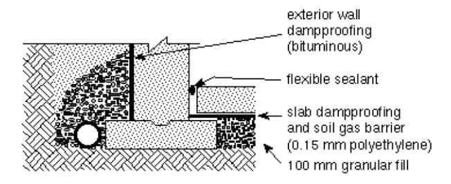
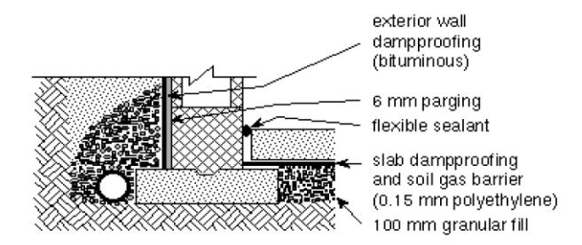
The requirements for Soil Gas Control in Walls, Soil Gas Barriers, and Sealing of the Perimeter and Penetrations, are illustrated in the following drawings. Sealing of penetrations of the slab also applies to hollow metal and masonry columns. Not only the perimeters but also the centres of such columns must be sealed or blocked.
Figure SB-9A Dampproofing and Soil Gas Control at Foundation Wall/Floor Junctions with Solid Walls
The requirement regarding drainage openings in slabs can be satisfied with any of a number of proprietary devices which prevent soil gas entry through floor drains. Some types of floor drains incorporate a trap which is connected to a nearby tap so that the trap is filled every time the tap is used. This is intended to prevent the entry of sewer gas but would be equally effective against the entry of soil gas.
Figure SB-9B Dampproofing and Soil Gas Control at Foundation Wall/Floor Junctions with Hollow Walls
There are two primary purposes for excluding soil gas:
- Sealing the interface between the soil and the occupied space, so far as is reasonably practicable, and
- Ensuring that the pressure difference across the soil/space interface is positive (i.e., towards the outside) so that inward soil gas flow through any remaining leaks will be prevented.
Effective Depressurization.
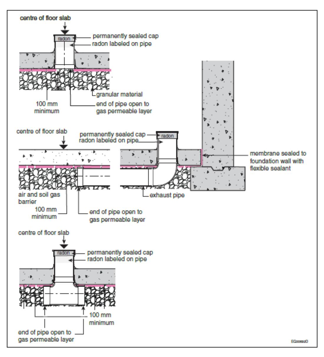
To allow effective depressurization of the space between the gas barrier and the ground, the extraction opening (the pipe) should not be blocked and should be arranged such that air can be extracted from the entire space between the gas barrier and the ground. This will ensure that the extraction system can maintain negative pressure underneath the entire floor (or in heated crawl spaces underneath the air barrier). The arrangement and location of the extraction system inlets(s) may have design implications where the footing layout separates part of the space underneath the floor.
Radon Testing and Active Depressurization Systems.
Where radon concentration testing is carried out, it should be done in accordance with HC Pub. 4171, "Guide for Radon Measurements in Residential Dwellings (Homes), 2008", to determine the radon concentration in the building. The sampling should include basement concentration measurements. If the average annual radon concentration determined exceeds 200 Bq/m3 in the normal occupancy area, measures, such as the conversion of rough-in system to an active subfloor depressurization system, need to be taken to reduce the radon concentration to a level below 200 Bq/m3 in the normal occupancy area.
Where an active subfloor depressurization system is installed, the following needs to be taken into consideration:
- provision to provide makeup air in accordance with Article 9.32.3.8. of Division B of the Building Code, and
- measures to ensure that any resultant decrease in soil temperature will not adversely affect the foundation.
Figure SB-9C Acceptable Configurations for the Extraction Opening in a Depressurization System