

SB-3 — Fire and Sound Resistance Tables
(This Standard is based in large measure on the Fire and Sound Resistance Tables of the National Building Code of Canada 2020)
The following Tables may be used to select building assemblies for compliance with Articles 5.8.1.3., Sentence 9.10.3.1.(1), Articles 9.10.5.1., 9.11.1.3., 9.11.1.4. and Sentence 9.29.5.9.(5) of Division B of the 2024 Building Code.
Tables 1 and 2 have been developed from information gathered from tests. While a large number of the assemblies listed were tested, the fire-resistance and acoustical ratings for others were assigned on the basis of extrapolation of information from tests of similar assemblies. Where there was enough confidence relative to the fire performance of an assembly, the fire-resistance ratings were assigned relative to the commonly used minimum ratings of 30 min, 45 min and 1 h, including a designation of "< 30 min" for assemblies that are known not to meet the minimum 30-minute rating. Where there was not enough comparative information on an assembly to assign to it a rating with confidence, its value in the Tables has been left blank (hyphen), indicating that its rating remains to be assessed through another means
These Tables are provided only for the convenience of Code users and do not limit the number of assemblies permitted to those in the Tables. The notes to Tables 1 and 2 are mandatory parts of the Tables and must be used by designers in complying with the design requirements of a particular assembly. Assemblies not listed or not given a rating in these Tables are equally acceptable provided their fire and sound resistance can be demonstrated to meet the above-noted requirements either on the basis of tests referred to in Article 9.10.3.1. and Subsection 9.11.1. or by using the data in MMAH Supplementary Standard SB-2, "Fire-Performance Ratings". It should be noted, however, that Tables 1 and 2 of this Supplementary Standard are not based on the same assumptions as those used in MMAH Supplementary Standard SB-2. Assemblies in Tables 1 and 2 are described through their generic descriptions and variants and the important details given in the notes to the Tables. Assumptions for MMAH Supplementary Standard SB-2 include different construction details that must be followed rigorously for the calculated ratings to be expected. These are two different methods of choosing assemblies that meet required fire ratings.
Table 2 presents fire-resistance and acoustical ratings for floor, ceiling and roof assemblies. The fire-resistance ratings are appropriate for all assemblies conforming to the construction specifications given in Table 2, including applicable Table notes. Acoustical ratings for assemblies decrease with decreasing depth and decreasing separation of the structural members; the values listed for sound transmission class and impact insulation class are suitable for the minimum depth of structural members identified in the description, including applicable Table notes, and for structural member spacing of 305 mm o.c., unless other values are explicitly listed for the assembly. Adjustments to the acoustical ratings to allow for the benefit of deeper or more widely spaced structural members are given in Table Notes (9) and (10).
For wall, floor and ceiling assemblies, framing spacing previously specified as 16 and 24 inch on centre has been converted to 406 and 610 mm respectively to represent actual framing spacing used in the field to accommodate modular sheathing panel dimensions. These metric dimensions are deemed to comply with test results based on reported framing spacing of 400 mm or 600 mm on centre.
Section 1 Fire and Sound Resistance of Walls
Table 1 Fire and Sound Resistance of Walls[1]
Type of Wall
- Wood Studs
- Single Row
- Loadbearing or Non-Loadbearing
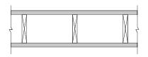
Wall Number: W1
- 38 mm × 89 mm wood studs spaced 406 mm or 610 mm o.c.
- with or without absorptive material
- 1 layer of gypsum board on each side
| Wall Number | Description | Fire-Resistance Rating - Loadbearing | Fire-Resistance Rating - Non-Loadbearing | Typical Sound Transmission Class[2] [4] [5] (STC) |
|---|---|---|---|---|
| W1a | W1 with | 1 h | 1 h | 36 |
| W1b | W1 with | 45 min [1 h][8] | 45 min [1 h][8] | 34 |
| W1c | W1 with | 30 min | 30 min [45 min][8] | 32 |
| W1d | W1 with
| 1 h | 1 h | 32 |
| W1e | W1 with
| 45 min | 45 min | 32 |
| Column 2 | 3 | 4 | 5 | 6 |
Type of Wall
- Wood Studs
- Single Row
- Loadbearing or Non-Loadbearing
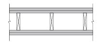
Wall Number: W2
- 38 mm × 89 mm wood studs spaced 406 mm or 610 mm o.c.
- with or without absorptive material
- 2 layers of gypsum board on each side
| Wall Number | Description | Fire-Resistance Rating - Loadbearing | Fire-Resistance Rating - Non-Loadbearing | Typical Sound Transmission Class[2] [4] [5] (STC) |
|---|---|---|---|---|
| W2a | W2 with | 1.5 h | 2 h | 38 |
| W2b | W2 with | 1 h | 1.5 h | 38 |
| W2c | W2 with | 45 min | 1 h | 36 |
| W2d | W2 with
| 1.5 h | 2 h | 36 |
| W2e | W2 with
| 1 h | 1.5 h | 35 |
| W2f | W2 with
| 45 min | 1 h | 34 |
| Column 2 | 3 | 4 | 5 | 6 |
Type of Wall
- Wood Studs
- Single Row
- Loadbearing or Non-Loadbearing
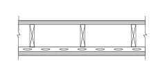
Wall Number: W3
- 38 mm × 89 mm wood studs spaced 406 mm or 610 mm o.c.
- 89 mm thick absorptive material[6]
- resilient metal channels on one side spaced 406 mm or 610 mm o.c.
- 1 layer of gypsum board on each side
| Wall Number | Description | Fire-Resistance Rating - Loadbearing | Fire-Resistance Rating - Non-Loadbearing | Typical Sound Transmission Class[2] [4] [5] (STC) |
|---|---|---|---|---|
| W3a | W3 with
| 45 min | 1 h | 45 |
| W3b | W3 with
| 45 min | 1 h | 48 |
| W3c | W3 with
| 45 min | 45 min | 43 |
| Column 2 | 3 | 4 | 5 | 6 |
Type of Wall
- Wood Studs
- Single Row
- Loadbearing or Non-Loadbearing
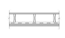
Wall Number: W4
- 38 mm × 89 mm wood studs spaced 406 mm or 610 mm o.c.
- 89 mm thick absorptive material[6]
- resilient metal channels on one side spaced 406 mm or 610 mm o.c.
- 2 layers of gypsum board on resilient metal channel side
- 1 layer of gypsum board on other side
| Wall Number | Description | Fire-Resistance Rating - Loadbearing | Fire-Resistance Rating - Non-Loadbearing | Typical Sound Transmission Class[2] [4] [5] (STC) |
|---|---|---|---|---|
| W4a | W4 with
| 1 h | 1 h [1.5 h][8] | 51 |
| W4b | W4 with
| 1 h | 1 h [1.5 h][8] | 54 |
| W4c | W4 with
| 45 min [1 h][8] | 1 h | 49 |
| W4d | W4 with
| 45 min [1 h][8] | 1 h | 53 |
| Column 2 | 3 | 4 | 5 | 6 |
Type of Wall
- Wood Studs
- Single Row
- Loadbearing or Non-Loadbearing
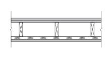
Wall Number: W5
- 38 mm × 89 mm wood studs spaced 406 mm or 610 mm o.c.
- 89 mm thick absorptive material[6]
- resilient metal channels on one side spaced 406 mm or 610 mm o.c.
- 1 layer of gypsum board on resilient metal channel side
- 2 layers of gypsum board on other side
| Wall Number | Description | Fire-Resistance Rating - Loadbearing | Fire-Resistance Rating - Non-Loadbearing | Typical Sound Transmission Class[2] [4] [5] (STC) |
|---|---|---|---|---|
| W5a | W5 with
| 45 min | 1 h | 51 |
| W5b | W5 with
| 45 min | 1 h | 54 |
| W5c | W5 with
| 45 min | 1 h | 49 |
| W5d | W5 with
| 45 min | 1 h | 53 |
| Column 2 | 3 | 4 | 5 | 6 |
Type of Wall
- Wood Studs
- Single Row
- Loadbearing or Non-Loadbearing
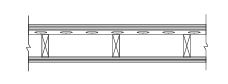
Wall Number: W6
- 38 mm × 89 mm wood studs spaced 406 mm or 610 mm o.c.
- with or without absorptive material
- resilient metal channels on one side
- 2 layers of gypsum board on each side
| Wall Number | Description | Fire-Resistance Rating - Loadbearing | Fire-Resistance Rating - Non-Loadbearing | Typical Sound Transmission Class[2] [4] [5] (STC) |
|---|---|---|---|---|
| W6a | W6 with | 1.5 h | 2 h | 55 |
| W6b | W6 with | 2 h | 2 h | – |
| W6c | W6 with | 2 h | 2 h | – |
| W6d | W6 with | 1.5 h | 2 h | 58 |
| W6e | W6 with | 1 h | 1.5 h | 53 |
| W6f | W6 with | 1 h | 1.5 h | 55 |
| W6g | W6 with | 1 h | 1.5 h | 55 |
| W6h | W6 with | 1 h | 1.5 h | 58 |
| W6i | W6 with
| 1.5 h | 2 h | 47 |
| W6j | W6 with
| 1 h | 1.5 h | 46 |
| Column 2 | 3 | 4 | 5 | 6 |
Type of Wall
- Wood Studs
- Two Rows Staggered on 38 mm × 140 mm plate
- Loadbearing or Non-Loadbearing
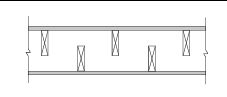
Wall Number: W7
- two rows 38 mm × 89 mm wood studs each spaced 406 mm or 610 mm o.c. staggered on common 38 mm × 140 mm plate
- 89 mm thick absorptive material on one side or 65 mm thick on each side[6]
- 1 layer of gypsum board on each side
| Wall Number | Description | Fire-Resistance Rating - Loadbearing | Fire-Resistance Rating - Non-Loadbearing | Typical Sound Transmission Class[2] [4] [5] (STC) |
|---|---|---|---|---|
| W7a | W7 with
| 1 h | 1 h | 47 |
| W7b | W7 with
| 45 min [1 h][8] | 45 min [1 h][8] | 45 |
| W7c | W7 with | 30 min | 30 min [45 min][8] | 42 |
| Column 2 | 3 | 4 | 5 | 6 |
Type of Wall
- Wood Studs
- Two Rows Staggered on 38 mm × 140 mm plate
- Loadbearing or Non-Loadbearing
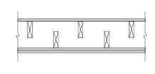
Wall Number: W8
- two rows 38 mm × 89 mm wood studs each spaced 406 mm or 610 mm o.c. staggered on common 38 mm × 140 mm plate
- 89 mm thick absorptive material on one side or 65 mm thick on each side[6]
- 2 layers of gypsum board on one side
- 1 layer of gypsum board on other side
| Wall Number | Description | Fire-Resistance Rating - Loadbearing | Fire-Resistance Rating - Non-Loadbearing | Typical Sound Transmission Class[2] [4] [5] (STC) |
|---|---|---|---|---|
| W8a | W8 with
| 1 h | 1.5 h | 52 |
| W8b | W8 with
| 45 min | 1 h | 50 |
| Column 2 | 3 | 4 | 5 | 6 |
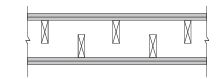
Type of Wall
- Wood Studs
- Two Rows Staggered on 38 mm × 140 mm plate
- Loadbearing or Non-Loadbearing
Wall Number: W9
- two rows 38 mm × 89 mm wood studs each spaced 406 mm or 610 mm o.c. staggered on common 38 mm × 140 mm plate
- with or without absorptive material
- 2 layers of gypsum board on each side
| Wall Number | Description | Fire-Resistance Rating - Loadbearing | Fire-Resistance Rating - Non-Loadbearing | Typical Sound Transmission Class[2] [4] [5] (STC) |
|---|---|---|---|---|
| W9a | W9 with | 1.5 h | 2 h | 56 |
| W9b | W9 with | 1 h | 1.5 h | 55 |
| W9c | W9 with | 45 min | 1 h | 53 |
| W9d | W9 with
| 1.5 h | 2 h | 48 |
| Column 2 | 3 | 4 | 5 | 6 |
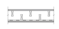
Type of Wall
- Wood Studs
- Two Rows Staggered on 38 mm × 140 mm plate
- Loadbearing or Non-Loadbearing
Wall Number: W10
- two rows 38 mm × 89 mm wood studs each spaced 406 mm or 610 mm o.c. staggered on common 38 mm × 140 mm plate
- with or without absorptive material
- resilient metal channels on one side spaced 406 mm or 610 mm o.c.
- 2 layers of gypsum board on each side
| Wall Number | Description | Fire-Resistance Rating - Loadbearing | Fire-Resistance Rating - Non-Loadbearing | Typical Sound Transmission Class[2] [4] [5] (STC) |
|---|---|---|---|---|
| W10a | W10 with | 1.5 h | 2 h | 62 |
| W10b | W10 with | 1 h | 1.5 h | 60 |
| W10c | W10 with
| 1.5 h | 2 h | 50 |
| W10d | W10 with
| 1 h | 1.5 h | 48 |
| Column 2 | 3 | 4 | 5 | 6 |
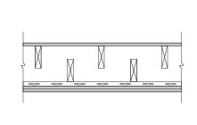
Type of Wall
- Wood Studs
- Two Rows Staggered on 38 mm × 140 mm plate
- Loadbearing or Non-Loadbearing
Wall Number: W11
- two rows 38 mm × 89 mm wood studs each spaced 406 mm or 610 mm o.c. staggered on common 38 mm × 140 mm plate
- 89 mm thick absorptive material on one side or 65 mm thick on each side[6]
- resilient metal channels on one side spaced 406 mm or 610 mm o.c.
- 2 layers of gypsum board on resilient channel side
- 1 layer of gypsum board on other side
| Wall Number | Description | Fire-Resistance Rating - Loadbearing | Fire-Resistance Rating - Non-Loadbearing | Typical Sound Transmission Class[2] [4] [5] (STC) |
|---|---|---|---|---|
| W11a | W11 with
| 1 h | 1 h | 56 |
| W11b | W11 with
| 45 min [1 h][8] | 1 h | 54 |
| Column 2 | 3 | 4 | 5 | 6 |
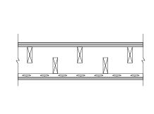
Type of Wall
- Wood Studs
- Two Rows Staggered on 38 mm × 140 mm plate
- Loadbearing or Non-Loadbearing
Wall Number: W12
- two rows 38 mm × 89 mm wood studs each spaced 406 mm or 610 mm o.c. staggered on common 38 mm × 140 mm plate
- 89 mm thick absorptive material on one side or 65 mm thick on each side[6]
- resilient metal channels on one side spaced 406 mm or 610 mm o.c.
- 1 layer of gypsum board on resilient metal channel side
- 2 layers of gypsum board on other side
| Wall Number | Description | Fire-Resistance Rating - Loadbearing | Fire-Resistance Rating - Non-Loadbearing | Typical Sound Transmission Class[2] [4] [5] (STC) |
|---|---|---|---|---|
| W12a | W12 with
| 45 min | 1 h | 56 |
| W12b | W12 with
| 45 min | 1 h | 54 |
| Column 2 | 3 | 4 | 5 | 6 |
Type of Wall
- Wood Studs
- Two Rows on Separate Plates
- Loadbearing or Non-Loadbearing
Wall Number: W13
- two rows 38 mm × 89 mm wood studs each spaced 406 mm or 610 mm o.c. on separate 38 mm × 89 mm plates set 25 mm apart
- with or without absorptive material
- 1 layer of gypsum board on each side
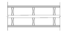
| Wall Number | Description | Fire-Resistance Rating - Loadbearing | Fire-Resistance Rating - Non-Loadbearing | Typical Sound Transmission Class[2] [4] [5] (STC) |
|---|---|---|---|---|
| W13a | W13 with | 1 h | 1 h | 57 |
| W13b | W13 with | 45 min [1 h][8] | 45 min [1 h][8] | 57 |
| W13c | W13 with | 1 h | 1 h | 54 |
| W13d | W13 with | 45 min | 45 min | 53 |
| W13e | W13 with
| 1 h | 1 h | 45 |
| W13f | W13 with
| 45 min | 45 min | 45 |
| Column 2 | 3 | 4 | 5 | 6 |
Type of Wall
- Wood Studs
- Two Rows on Separate Plates
- Loadbearing or Non-Loadbearing
Wall Number: W14
- two rows 38 mm × 89 mm wood studs each spaced 406 mm or 610 mm o.c. on separate 38 mm × 89 mm plates set 25 mm apart
- with or without absorptive material
- 2 layers of gypsum board on one side
- 1 layer of gypsum board on other side
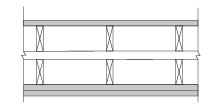
| Wall Number | Description | Fire-Resistance Rating - Loadbearing | Fire-Resistance Rating - Non-Loadbearing | Typical Sound Transmission Class[2] [4] [5] (STC) |
|---|---|---|---|---|
| W14a | W14 with | 1 h | 1 h [1.5 h][8] | 61 |
| W14b | W14 with | 45 min | 1 h | 61 |
| W14c | W14 with | 1 h | 1 h | 57 |
| W14d | W14 with | 45 min | 1 h | 57 |
| W14e | W14 with
| 1 h | 1 h | 51 |
| W14f | W14 with
| 45 min | 1 h | 51 |
| Column 2 | 3 | 4 | 5 | 6 |
Type of Wall
- Wood Studs
- Two Rows on Separate Plates
- Loadbearing or Non-Loadbearing
Wall Number: W15
- two rows 38 mm × 89 mm wood studs each spaced 406 mm or 610 mm o.c. on separate 38 mm × 89 mm plates set 25 mm apart
- with or without absorptive material
- 2 layers of gypsum board on each side
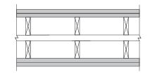
| Wall Number | Description | Fire-Resistance Rating - Loadbearing | Fire-Resistance Rating - Non-Loadbearing | Typical Sound Transmission Class[2] [4] [5] (STC) |
|---|---|---|---|---|
| W15a | W15 with | 1.5 h | 2 h | 66 |
| W15b | W15 with | 1 h | 1.5 h | 65 |
| W15c | W15 with | 45 min | 1 h | 61 |
| W15d | W15 with | 1.5 h | 2 h | 62 |
| W15e | W15 with | 1 h | 1.5 h | 60 |
| W15f | W15 with | 45 min | 1 h | 57 |
| W15g | W15 with
| 1.5 h | 2 h | 56 |
| W15h | W15 with
| 1 h | 1.5 h | 55 |
| W15i | W15 with
| 45 min | 1 h | 51 |
| Column 2 | 3 | 4 | 5 | 6 |
Type of Wall
- Wood Studs
- Two Rows on Separate Plates
- Loadbearing or Non-Loadbearing
Wall Number: W16
- two rows 38 mm × 89 mm studs, each spaced 406 mm or 610 mm o.c. on separate 38 mm × 89 mm plates set 25 mm apart
- resilient metal channels on one side spaced 406 mm or 610 mm o.c.
- with or without absorptive material
- 2 layers of gypsum board on each side
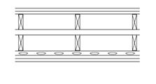
| Wall Number | Description | Fire-Resistance Rating - Loadbearing | Fire-Resistance Rating - Non-Loadbearing | Typical Sound Transmission Class[2] [4] [5] (STC) |
|---|---|---|---|---|
| W16a | W16 with | 1.5 h | 2 h | 66 |
| W16b | W16 with | 2 h | 2 h | – |
| W16c | W16 with | 1 h | 1.5 h | 65 |
| W16d | W16 with | 1.5 h | 2 h | 62 |
| W16e | W16 with | 1 h | 1.5 h | 60 |
| W16f | W16 with
| 1.5 h | 2 h | 56 |
| W16g | W16 with
| 1 h | 1.5 h | 55 |
| Column 2 | 3 | 4 | 5 | 6 |
Type of Wall
- Exterior
- Wood Studs
- Single Row
- Loadbearing and Non-Loadbearing
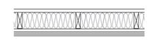
Wall Number: EW1
- wood studs
- rock or slag fibre insulation[11]
- 1 layer of gypsum board on inside
- exterior sheathing and cladding
| Wall Number | Description | Fire-Resistance Rating - Loadbearing | Fire-Resistance Rating - Non-Loadbearing | Typical Sound Transmission Class[2] [4] [5] (STC) |
|---|---|---|---|---|
| EW1a | EW1 with | 1 h | 1 h | N/A |
| EW1b | EW1 with | 45 min | 1 h | N/A |
| EW1c | EW1 with | 45 min | 1 h | N/A |
| EW1d | EW1 with | – | 45 min | N/A |
| EW1e | EW1 with | 45 min | 45 min | N/A |
| Column 2 | 3 | 4 | 5 | 6 |
Type of Wall
- Exterior
- Wood Studs
- Single Row
- Loadbearing and Non-Loadbearing
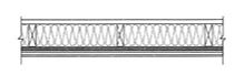
Wall Number: EW2
- wood studs
- glass fibre insulation[21]
- 1 layer of gypsum board on inside
- exterior sheathing and cladding
| Wall Number | Description | Fire-Resistance Rating - Loadbearing | Fire-Resistance Rating - Non-Loadbearing | Typical Sound Transmission Class[2] [4] [5] (STC) |
|---|---|---|---|---|
| EW2a | EW2 with | 1 h | 1 h | N/A |
| EW2b | EW2 with | 45 min | 1 h | N/A |
| EW2c | EW2 with | 45 min | 1 h | N/A |
| EW2d | EW2 with | N/A | 45 min | N/A |
| EW2e | EW2 with | N/A | 45 min | N/A |
| EW2f | EW2 with | 45 min | 1 h | N/A |
| EW2g | EW2 with | – | 45 min | N/A |
| EW2h | EW2 with | – | 45 min | N/A |
| EW2i | EW2 with | – | 45 min | N/A |
| EW2j | EW2 with | 45 min | 45 min | N/A |
| Column 2 | 3 | 4 | 5 | 6 |
Type of Wall
- Exterior
- Wood Studs
- Single Row
- Loadbearing and Non-Loadbearing
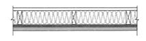
Wall Number: EW3
- wood studs
- dry-blown cellulose fibre insulation[12]
- 1 layer of gypsum board on inside
- exterior sheathing and cladding
| Wall Number | Description | Fire-Resistance Rating - Loadbearing | Fire-Resistance Rating - Non-Loadbearing | Typical Sound Transmission Class[2] [4] [5] (STC) |
|---|---|---|---|---|
| EW3a | EW3 with | 1 h | 1 h | N/A |
| EW3b | EW3 with | 1 h | 1 h | N/A |
| EW3c | EW3 with | 45 min | 1 h | N/A |
| EW3d | EW3 with | 45 min | 1 h | N/A |
| EW3e | EW3 with | 45 min | 1 h | N/A |
| EW3f | EW3 with | 45 min | 1 h | N/A |
| EW3g | EW3 with | 45 min | 1 h | N/A |
| EW3h | EW3 with | N/A | 45 min | N/A |
| EW3i | EW3 with | N/A | 45 min | N/A |
| EW3j | EW3 with | N/A | 45 min | N/A |
| EW3k | EW3 with | 45 min | 45 min | N/A |
| Column 2 | 3 | 4 | 5 | 6 |
Type of Wall
- Non-Loadbearing Steel Studs
- 0.46 mm (25 Gauge)
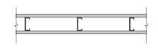
Wall Number: S1
- 31 mm × 64 mm steel studs spaced 406 mm or 610 mm o.c.
- with or without absorptive material
- 1 layer of gypsum board on each side
| Wall Number | Description | Fire-Resistance Rating - Loadbearing | Fire-Resistance Rating - Non-Loadbearing | Typical Sound Transmission Class[2] [4] [5] (STC) |
|---|---|---|---|---|
| S1a | S1 with | N/A | 45 min [1 h][8] | 43 |
| S1b | S1 with | N/A | 45 min [1 h][8] | 39 |
| S1c | S1 with
| N/A | 45 min | 35 |
| Column 2 | 3 | 4 | 5 | 6 |
Type of Wall
- Non-Loadbearing Steel Studs
- 0.46 mm (25 Gauge)
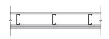
Wall Number: S2
- 31 mm × 64 mm steel studs spaced 406 mm or 610 mm o.c.
- with or without absorptive material
- 1 layer of gypsum board on one side
- 2 layers of gypsum board on other side
| Wall Number | Description | Fire-Resistance Rating - Loadbearing | Fire-Resistance Rating - Non-Loadbearing | Typical Sound Transmission Class[2] [4] [5] (STC) |
|---|---|---|---|---|
| S2a | S2 with | N/A | 1 h | 50 |
| S2b | S2 with | N/A | 1 h | 44 |
| S2c | S2 with | N/A | 1 h | 50 |
| S2d | S2 with | N/A | 1 h | 42 |
| S2e | S2 with
| N/A | 1 h | 41 |
| S2f | S2 with
| N/A | 1 h | 37 |
| S2g | S2 with
| N/A | 1 h | 40 |
| S2h | S2 with
| N/A | 1 h | 35 |
| Column 2 | 3 | 4 | 5 | 6 |
Type of Wall
- Non-Loadbearing Steel Studs
- 0.46 mm (25 Gauge)
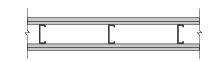
Wall Number: S3
- 31 mm × 64 mm steel studs spaced 406 mm or 610 mm o.c.
- with or without absorptive material
- 2 layers of gypsum board on each side
| Wall Number | Description | Fire-Resistance Rating - Loadbearing | Fire-Resistance Rating - Non-Loadbearing | Typical Sound Transmission Class[2] [4] [5] (STC) |
|---|---|---|---|---|
| S3a | S3 with | N/A | 2 h | 54 |
| S3b | S3 with | N/A | 2 h | 51 |
| S3c | S3 with | N/A | 1.5 h | 53 |
| S3d | S3 with | N/A | 1.5 h | 47 |
| S3e | S3 with | N/A | 1 h | 49 |
| S3f | S3 with | N/A | 1 h | 41 |
| S3g | S3 with
| N/A | 2 h | 45 |
| S3h | S3 with
| N/A | 2 h | 42 |
| S3i | S3 with
| N/A | 1.5 h | 44 |
| S3j | S3 with
| N/A | 1.5 h | 39 |
| S3k | S3 with
| N/A | 1 h | 40 |
| S3l | S3 with
| N/A | 1 h | 37 |
| Column 2 | 3 | 4 | 5 | 6 |
Type of Wall
- Non-Loadbearing Steel Studs
- 0.46 mm (25 Gauge)
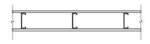
Wall Number: S4
- 31 mm × 92 mm steel studs spaced 406 mm or 610 mm o.c.
- with or without absorptive material
- 1 layer of gypsum board on each side
| Wall Number | Description | Fire-Resistance Rating - Loadbearing | Fire-Resistance Rating - Non-Loadbearing | Typical Sound Transmission Class[2] [4] [5] (STC) |
|---|---|---|---|---|
| S4a | S4 with | N/A | 45 min [1 h][8] | 48 |
| S4b | S4 with | N/A | 45 min [1 h][8] | 47 |
| S4c | S4 with
| N/A | 45 min | 38 |
| S4d | S4 with
| N/A | 45 min | 38 |
| Column 2 | 3 | 4 | 5 | 6 |
Type of Wall
- Non-Loadbearing Steel Studs
- 0.46 mm (25 Gauge)
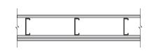
Wall Number: S5
- 31 mm × 92 mm steel studs spaced 406 mm or 610 mm o.c.
- with or without absorptive material
- 1 layer of gypsum board on one side
- 2 layers of gypsum board on other side
| Wall Number | Description | Fire-Resistance Rating - Loadbearing | Fire-Resistance Rating - Non-Loadbearing | Typical Sound Transmission Class[2] [4] [5] (STC) |
|---|---|---|---|---|
| S5a | S5 with | N/A | 1 h [1.5 h][8] | 53 |
| S5b | S5 with | N/A | 1 h [1.5 h][8] | 52 |
| S5c | S5 with | N/A | 1 h [1.5 h][8] | 51 |
| S5d | S5 with | N/A | 1 h [1.5 h][8] | 50 |
| S5e | S5 with
| N/A | 1 h | 43 |
| S5f | S5 with
| N/A | 1 h | 42 |
| S5g | S5 with
| N/A | 1 h | 41 |
| S5h | S5 with
| N/A | 1 h | 40 |
| Column 2 | 3 | 4 | 5 | 6 |
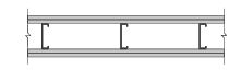
Type of Wall
- Non-Loadbearing Steel Studs
- 0.46 mm (25 Gauge)
Wall Number: S6
- 31 mm × 92 mm steel studs spaced 406 mm or 610 mm o.c.
- with or without absorptive material
- 2 layers of gypsum board on each side
| Wall Number | Description | Fire-Resistance Rating - Loadbearing | Fire-Resistance Rating - Non-Loadbearing | Typical Sound Transmission Class[2] [4] [5] (STC) |
|---|---|---|---|---|
| S6a | S6 with | N/A | 2 h | 56 |
| S6b | S6 with | N/A | 2 h | 55 |
| S6c | S6 with | N/A | 1.5 h | 55 |
| S6d | S6 with | N/A | 1.5 h | 54 |
| S6e | S6 with | N/A | 1 h | 50 |
| S6f | S6 with | N/A | 1 h | 48 |
| S6g | S6 with
| N/A | 2 h | 47 |
| S6h | S6 with
| N/A | 2 h | 45 |
| S6i | S6 with
| N/A | 1.5 h | 45 |
| S6j | S6 with
| N/A | 1.5 h | 44 |
| S6k | S6 with
| N/A | 1 h | 41 |
| S6l | S6 with
| N/A | 1 h | 39 |
| Column 2 | 3 | 4 | 5 | 6 |
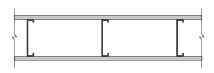
Type of Wall
- Non-Loadbearing Steel Studs
- 0.46 mm (25 Gauge)
Wall Number: S7
- 31 mm × 152 mm steel studs spaced 406 mm or 610 mm o.c.
- with or without absorptive material
- 1 layer of gypsum board on each side
| Wall Number | Description | Fire-Resistance Rating - Loadbearing | Fire-Resistance Rating - Non-Loadbearing | Typical Sound Transmission Class[2] [4] [5] (STC) |
|---|---|---|---|---|
| S7a | S7 with | N/A | 45 min [1 h][8] | 51 |
| S7b | S7 with
| N/A | 45 min | 41 |
| Column 2 | 3 | 4 | 5 | 6 |
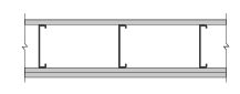
Type of Wall
- Non-Loadbearing Steel Studs
- 0.46 mm (25 Gauge)
Wall Number: S8
- 31 mm × 152 mm steel studs spaced 406 mm or 610 mm o.c.
- with or without absorptive material
- 1 layer of gypsum board on one side
- 2 layers of gypsum board on other side
| Wall Number | Description | Fire-Resistance Rating - Loadbearing | Fire-Resistance Rating - Non-Loadbearing | Typical Sound Transmission Class[2] [4] [5] (STC) |
|---|---|---|---|---|
| S8a | S8 with | N/A | 1 h [1.5 h][8] | 55 |
| S8b | S8 with | N/A | 1 h [1.5 h][8] | 54 |
| S8c | S8 with
| N/A | 1 h | 45 |
| S8d | S8 with
| N/A | 1 h | 44 |
| Column 2 | 3 | 4 | 5 | 6 |
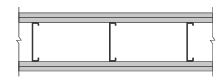
Type of Wall
- Non-Loadbearing Steel Studs
- 0.46 mm (25 Gauge)
Wall Number: S9
- 31 mm × 152 mm steel studs spaced 406 mm or 610 mm o.c.
- with or without absorptive material
- 2 layers of gypsum board on each side
| Wall Number | Description | Fire-Resistance Rating - Loadbearing | Fire-Resistance Rating - Non-Loadbearing | Typical Sound Transmission Class[2] [4] [5] (STC) |
|---|---|---|---|---|
| S9a | S9 with | N/A | 2 h | 59 |
| S9b | S9 with | N/A | 1.5 h | 57 |
| S9c | S9 with | N/A | 1 h | 53 |
| S9d | S9 with
| N/A | 2 h | 49 |
| S9e | S9 with
| N/A | 1.5 h | 47 |
| S9f | S9 with
| N/A | 1 h | 43 |
| Column 2 | 3 | 4 | 5 | 6 |
Type of Wall
- Loadbearing Steel Studs
- 0.84 mm to 1.52 mm thickness
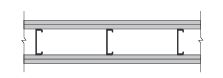
Wall Number: S10
- 41 mm × 92 mm loadbearing steel studs spaced 406 mm or 610 mm o.c.
- with or without cross-bracing on one side
- with or without absorptive material
- 2 layers of gypsum board on each side
| Wall Number | Description | Fire-Resistance Rating - Loadbearing | Fire-Resistance Rating - Non-Loadbearing | Typical Sound Transmission Class[2] [4] [5] (STC) |
|---|---|---|---|---|
| S10a | S10 with | 1 h | N/A | 38 |
| S10b | S10 with | 45 min [1 h][8] | N/A | 38 |
| S10c | S10 with | N/A | N/A | 36 |
| S10d | S10 with
| 1 h | N/A | 36 |
| S10e | S10 with
| 1 h | N/A | 35 |
| S10f | S10 with
| N/A | N/A | 34 |
| Column 2 | 3 | 4 | 5 | 6 |
Type of Wall
- Loadbearing Steel Studs
- 0.84 mm to 1.52 mm thickness
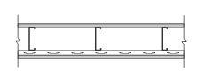
Wall Number: S11
- 41 mm × 92 mm loadbearing steel studs spaced 406 mm or 610 mm o.c.
- with or without cross-bracing on one side
- with or without absorptive material
- resilient metal channels on one side
- 1 layer of gypsum board on each side
| Wall Number | Description | Fire-Resistance Rating - Loadbearing | Fire-Resistance Rating - Non-Loadbearing | Typical Sound Transmission Class[2] [4] [5] (STC) |
|---|---|---|---|---|
| S11a | S11 with | N/A | N/A | 50 |
| S11b | S11 with | N/A | N/A | 47 |
| S11c | S11 with
| N/A | N/A | 41 |
| S11d | S11 with
| N/A | N/A | 39 |
| S11e | S11 with | N/A | N/A | 47 |
| S11f | S11 with | N/A | N/A | 45 |
| S11g | S11 with
| N/A | N/A | 38 |
| S11h | S11 with
| N/A | N/A | 36 |
| Column 2 | 3 | 4 | 5 | 6 |
Type of Wall
- Loadbearing Steel Studs
- 0.84 mm to 1.52 mm thickness
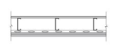
Wall Number: S12
- 41 mm × 92 mm loadbearing steel studs spaced 406 mm or 610 mm o.c.
- with or without cross-bracing on one side
- with or without absorptive material
- resilient metal channels on one side
- 2 layers of gypsum board on resilient channel side
- 1 layer of gypsum board on other side
| Wall Number | Description | Fire-Resistance Rating - Loadbearing | Fire-Resistance Rating - Non-Loadbearing | Typical Sound Transmission Class[2] [4] [5] (STC) |
|---|---|---|---|---|
| S12a | S12 with | N/A | N/A | 54 |
| S12b | S12 with | N/A | N/A | 52 |
| S12c | S12 with
| N/A | N/A | 46 |
| S12d | S12 with
| N/A | N/A | 43 |
| S12e | S12 with | N/A | N/A | 52 |
| S12f | S12 with | N/A | N/A | 50 |
| S12g | S12 with
| N/A | N/A | 43 |
| S12h | S12 with
| N/A | N/A | 41 |
| Column 2 | 3 | 4 | 5 | 6 |
Type of Wall
- Loadbearing Steel Studs
- 0.84 mm to 1.52 mm thickness
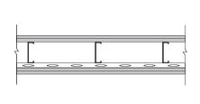
Wall Number: S13
- 41 mm × 92 mm loadbearing steel studs spaced 406 mm or 610 mm o.c.
- with or without absorptive material
- resilient metal channels on one side spaced at 406 mm o.c.
- 2 layers of gypsum board on resilient channel side
- 1 layer shear membrane and 1 layer gypsum board on other side
| Wall Number | Description | Fire-Resistance Rating - Loadbearing | Fire-Resistance Rating - Non-Loadbearing | Typical Sound Transmission Class[2] [4] [5] (STC) |
|---|---|---|---|---|
| S13a | S13 with | 30 min | N/A | 57 |
| Column 2 | 3 | 4 | 5 | 6 |
Type of Wall
- Loadbearing Steel Studs
- 0.84 mm to 1.52 mm thickness
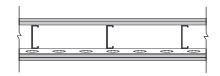
Wall Number: S14
- 41 mm × 92 mm loadbearing steel studs spaced 406 mm or 610 mm o.c.
- with or without absorptive material
- resilient metal channels on one side
- 2 layers of gypsum board on each side
| Wall Number | Description | Fire-Resistance Rating - Loadbearing | Fire-Resistance Rating - Non-Loadbearing | Typical Sound Transmission Class[2] [4] [5] (STC) |
|---|---|---|---|---|
| S14a | S14 with | 1 h | N/A | 60 |
| S14b | S14 with | 45 min [1 h][8] | N/A | 57 |
| S14c | S14 with | N/A | N/A | 54 |
| S14d | S14 with
| 45 min [1 h][8] | N/A | 55 |
| S14e | S14 with
| 1 h | N/A | 51 |
| S14f | S14 with
| N/A | N/A | 45 |
| S14g | S14 with
| 1 h | N/A | 47 |
| S14h | S14 with
| 1 h | N/A | 60 |
| S14i | S14 with
| 1 h | N/A | 58 |
| S14j | S14 with
| 1 h | N/A | 51 |
| S14k | S14 with
| 1 h | N/A | 49 |
| S14l | S14 with
| 1 h | N/A | 49 |
| S14m | S14 with
| 1 h | N/A | 50 |
| Column 2 | 3 | 4 | 5 | 6 |
Type of Wall
- Loadbearing Steel Studs
- 0.84 mm to 1.52 mm thickness
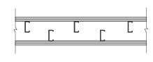
Wall Number: S15
- 2 rows of 41 mm × 92 mm loadbearing steel studs spaced 406 mm or 610 mm o.c. staggered on 152 mm common plate
- with cross-bracing
- with or without absorptive material
- 2 layers of gypsum board on each side
| Wall Number | Description | Fire-Resistance Rating - Loadbearing | Fire-Resistance Rating - Non-Loadbearing | Typical Sound Transmission Class[2] [4] [5] (STC) |
|---|---|---|---|---|
| S15a | S15 with | 1 h | N/A | 68 |
| S15b | S15 with | 1 h | N/A | 68 |
| S15c | S15 with
| 1.5 h | N/A | 52 |
| S15d | S15 with
| 1 h | N/A | 52 |
| Column 2 | 3 | 4 | 5 | 6 |
Type of Wall
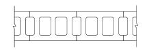
- Hollow Concrete Block (Normal Weight Aggregate)
Wall Number: B1
- 140 mm or 190 mm concrete block
| Wall Number | Description | Fire-Resistance Rating - Loadbearing | Fire-Resistance Rating - Non-Loadbearing | Typical Sound Transmission Class[2] [4] [5] (STC) |
|---|---|---|---|---|
| B1a | 140 mm bare concrete block[5] | 1 h | 1 h | 48 |
| B1b | 190 mm bare concrete block[5] | 1.5 h | 1.5 h | 50 |
| Column 2 | 3 | 4 | 5 | 6 |
Type of Wall
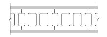
- Hollow Concrete Block (Normal Weight Aggregate)
Wall Number: B2
- 140 mm or 190 mm concrete block
- no absorptive material
- 1 layer of gypsum-sand plaster or gypsum board on each side
| Wall Number | Description | Fire-Resistance Rating - Loadbearing | Fire-Resistance Rating - Non-Loadbearing | Typical Sound Transmission Class[2] [4] [5] (STC) |
|---|---|---|---|---|
| B2a | B2 with
| 2 h | 2 h | 50 |
| B2b | B2 with
| 2 h | 2 h | 47 |
| B2c | B2 with
| 1.5 h | 1.5 h | 46 |
| B2d | B2 with
| 2.5 h | 2.5 h | 51 |
| B2e | B2 with
| 3 h | 3 h | 50 |
| B2f | B2 with
| 2.5 h | 2.5 h | 49 |
| B2g | B2 with
| 2 h | 2 h | 48 |
| Column 2 | 3 | 4 | 5 | 6 |
Type of Wall
- Hollow Concrete Block (Normal Weight Aggregate)
Wall Number: B3
- 140 mm or 190 mm concrete block
- resilient metal channels on one side spaced at 406 mm or 610 mm o.c.
- absorptive material filling resilient metal channel space[6]
- 1 layer of gypsum board on each side
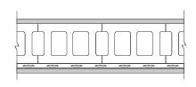
| Wall Number | Description | Fire-Resistance Rating - Loadbearing | Fire-Resistance Rating - Non-Loadbearing | Typical Sound Transmission Class[2] [4] [5] (STC) |
|---|---|---|---|---|
| B3a | B3 with
| 2 h | 2 h | 51 |
| B3b | B3 with | 1.5 h | 1.5 h | 48 |
| B3c | B3 with
| 3 h | 3 h | 54 |
| B3d | B3 with
| 2.5 h | 2.5 h | 53 |
| B3e | B3 with | 2 h | 2 h | 51 |
| Column 2 | 3 | 4 | 5 | 6 |
Type of Wall
- Hollow Concrete Block (Normal Weight Aggregate)
Wall Number: B4
- 140 mm or 190 mm concrete block
- resilient metal channels on each side spaced at 406 mm or 610 mm o.c.
- with or without absorptive material
- 1 layer of gypsum board on each side
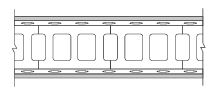
| Wall Number | Description | Fire-Resistance Rating - Loadbearing | Fire-Resistance Rating - Non-Loadbearing | Typical Sound Transmission Class[2] [4] [5] (STC) |
|---|---|---|---|---|
| B4a | B4 with
| 2 h | 2 h | 47 |
| B4b | B4 with | 1.5 h | 1.5 h | 42 |
| B4c | B4 with
| 3 h | 3 h | 50 |
| B4d | B4 with
| 2.5 h | 2.5 h | 49 |
| B4e | B4 with | 2 h | 2 h | 45 |
| Column 2 | 3 | 4 | 5 | 6 |
Type of Wall
- Hollow Concrete Block (Normal Weight Aggregate)
Wall Number: B5
- 190 mm concrete block
- 38 mm × 38 mm horizontal or vertical wood strapping on one side spaced at 610 mm o.c.
- with or without absorptive material
- 1 layer of gypsum board on each side
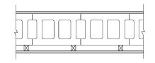
| Wall Number | Description | Fire-Resistance Rating - Loadbearing | Fire-Resistance Rating - Non-Loadbearing | Typical Sound Transmission Class[2] [4] [5] (STC) |
|---|---|---|---|---|
| B5a | B5 with
| 3 h | 3 h | 54 |
| B5b | B5 with
| 2.5 h | 2.5 h | 53 |
| B5c | B5 with | 2 h | 2 h | 51 |
| Column 2 | 3 | 4 | 5 | 6 |
Type of Wall
- Hollow Concrete Block (Normal Weight Aggregate)
Wall Number: B6
- 140 mm or 190 mm concrete block
- 38 mm × 38 mm horizontal or vertical wood strapping on each side spaced at 610 mm o.c.
- absorptive material filling strapping space on each side[6]
- 1 layer of gypsum board on each side
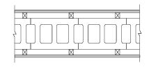
| Wall Number | Description | Fire-Resistance Rating - Loadbearing | Fire-Resistance Rating - Non-Loadbearing | Typical Sound Transmission Class[2] [4] [5] (STC) |
|---|---|---|---|---|
| B6a | B6 with
| 2 h | 2 h | 57 |
| B6b | B6 with | 1.5 h | 1.5 h | 56 |
| B6c | B6 with
| 3 h | 3 h | 60 |
| B6d | B6 with
| 2.5 h | 2.5 h | 59 |
| B6e | B6 with | 2 h | 2 h | 57 |
| Column 2 | 3 | 4 | 5 | 6 |
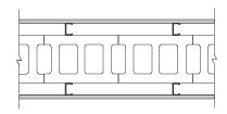
Type of Wall
- Hollow Concrete Block (Normal Weight Aggregate)
Wall Number: B7
- 190 mm concrete block
- 65 mm steel studs each side spaced at 610 mm o.c.
- absorptive material filling stud space on each side[6]
- 1 layer of gypsum board on each side
| Wall Number | Description | Fire-Resistance Rating - Loadbearing | Fire-Resistance Rating - Non-Loadbearing | Typical Sound Transmission Class[2] [4] [5] (STC) |
|---|---|---|---|---|
| B7a | B7 with
| 3 h | 3 h | 71 |
| B7b | B7 with
| 2.5 h | 2.5 h | 70 |
| B7c | B7 with | 2 h | 2 h | 69 |
| Column 2 | 3 | 4 | 5 | 6 |
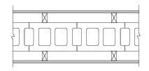
Type of Wall
- Hollow Concrete Block (Normal Weight Aggregate)
Wall Number: B8
- 190 mm concrete block
- 38 mm × 64 mm wood studs on each side spaced at 610 mm o.c.
- absorptive material filling stud space on each side[6]
- 1 layer of gypsum board on each side
| Wall Number | Description | Fire-Resistance Rating - Loadbearing | Fire-Resistance Rating - Non-Loadbearing | Typical Sound Transmission Class[2] [4] [5] (STC) |
|---|---|---|---|---|
| B8a | B8 with
| 3 h | 3 h | 71 |
| B8b | B8 with
| 2.5 h | 2.5 h | 70 |
| B8c | B8 with | 2 h | 2 h | 69 |
| Column 2 | 3 | 4 | 5 | 6 |
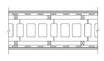
Type of Wall
- Hollow Concrete Block (Normal Weight Aggregate)
Wall Number: B9
- 190 mm concrete block
- 50 mm metal Z-bars on each side spaced at 610 mm o.c. (or 38 mm × 38 mm horizontal or vertical wood strapping plus resilient metal channels)
- absorptive material filling Z-bar space on each side[6]
- 1 layer of gypsum board on each side
| Wall Number | Description | Fire-Resistance Rating - Loadbearing | Fire-Resistance Rating - Non-Loadbearing | Typical Sound Transmission Class[2] [4] [5] (STC) |
|---|---|---|---|---|
| B9a | B9 with
| 3 h | 3 h | 65 |
| B9b | B9 with
| 2.5 h | 2.5 h | 64 |
| B9c | B9 with | 2 h | 2 h | 63 |
| Column 2 | 3 | 4 | 5 | 6 |
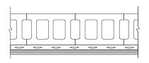
Type of Wall
- Hollow Concrete Block (Normal Weight Aggregate)
Wall Number: B10
- 190 mm concrete block
- resilient metal channels on one side spaced at 610 mm o.c.
- absorptive material filling resilient metal channel space[6]
- 2 layers of gypsum board on one side only
| Wall Number | Description | Fire-Resistance Rating - Loadbearing | Fire-Resistance Rating - Non-Loadbearing | Typical Sound Transmission Class[2] [4] [5] (STC) |
|---|---|---|---|---|
| B10a | B10 with
| 3 h | 3 h | 56 |
| B10b | B10 with
| 2.5 h | 2.5 h | 55 |
| B10c | B10 with
| 2 h | 2 h | 54 |
| Column 2 | 3 | 4 | 5 | 6 |
Notes to Table 1:
- Reserved.
Fire-resistance ratings and STC ratings of wood-frame construction were evaluated only for assemblies with solid-sawn 38 mm × 89 mm lumber. However, the fire-resistance ratings and STC ratings provided for 38 mm × 89 mm wood-frame assemblies may be applied to wood-frame assemblies with solid-sawn 38 mm × 140 mm lumber; in some cases the ratings may be conservative. Where 38 mm × 140 mm framing is used and absorptive material is called for, the absorptive material must be 140 mm thick. (See 1.2.1.(2) in MMAH Supplementary Standard SB-2 for the significance of fire-resistance ratings).
The STC ratings may also be applied to fingerjoined lumber. The fire-resistance ratings are applicable to wall assemblies using fingerjoined lumber that has been manufactured with a heat-resistant adhesive (HRA) in accordance with NLGA special product standard SPS-1-2017 "Fingerjoined Structural Lumber", or SPS-3-2017, "Fingerjoined 'Vertical Stud Use Only' Lumber". (See also Appendix Note A-9.23.10.4.(1) under Division B in Appendix A of the Building Code).
- For all fire-resistance ratings, the given spacing for framing is a maximum value.
- Sound ratings listed are based on the most reliable laboratory test data available for specimens conforming to installation details required by CSA A82.31-M1980, "Gypsum Board Application". Results of specific tests may differ slightly because of measurement precision and minor variations in construction details. These results should only be used where the actual construction details, including spacing of fasteners and supporting framing, correspond exactly to the details of the test specimens on which the ratings are based. For wood- and steel-framed assemblies, if the fasteners are spaced less than 300 mm o.c., subtract 1 from the sound transmission class value; if the fasteners are spaced less than 200 mm o.c., subtract 2 from the sound transmission class value. Narrower fastener spacing is not detrimental to the fire-resistance rating. Assemblies with sound transmission class ratings of 50 or more require methods to minimize airborne sound transmission at electrical boxes and other openings, and at the junction of intersecting walls and floors, except intersection of walls constructed of concrete or solid masonry units where the masonry joints at the intersection are mortared.
- Sound ratings are only valid where there are no discernible cracks or voids in the visible surfaces. For concrete block walls, surfaces must be sealed by at least 2 coats of paint or other surface finish described in Section 9.29. of Division B of the Building Code to prevent sound leakage.
- Sound absorptive material includes fibre processed from rock, slag, glass or cellulose fibre. It must fill at least 90% of the cavity thickness for the wall to provide the listed STC value. The absorptive material should not overfill the cavity to the point of producing significant outward pressure on the finishes; such an assembly will not achieve the STC rating. Where the absorptive material used with steel stud assemblies is in batt form, "steel stud batts", which are wide enough to fill the cavity from the web of one stud to the web of the adjacent studs, must be used.
- The complete descriptions of indicated finishes are as follows:
- 12.7 mm regular gypsum board — 12.7 mm regular gypsum board conforming to Article 9.29.5.2. of Division B of the Building Code.
- 12.7 mm Type X gypsum board — 12.7 mm special fire-resistant Type X gypsum board conforming to Article 9.29.5.2. of Division B of the Building Code.
- 15.9 mm Type X gypsum board — 15.9 mm special fire-resistant Type X gypsum board conforming to Article 9.29.5.2. of Division B of the Building Code.
- Except for exterior walls (see Note 15), the outer layer of finish on both sides of the wall must have its joints taped and finished.
- Except as otherwise required for fastener spacing (see Table Notes (14), (16) and (22)), fastener type, spacing and penetration depth for the attachment of gypsum board must conform to Subsection 9.29.5. of Division B of the Building Code and fasteners must consist of
- nails or screws when attaching gypsum board to wood studs or wood strapping, and
- screws when attaching gypsum board to cold-formed steel studs or resilient metal channels.
- Absorptive material required for the higher fire-resistance rating shall be mineral fibre processed from rock or slag with a mass per unit of wall surface of at least 4.8 kg/m² for 150 mm thickness, 2.8 kg/m² for 89 mm thickness and 2.0 kg/m² for 65 mm thickness and shall completely fill the wall cavity. For assemblies with double wood studs on separate plates, absorptive material is required in the stud cavities on both sides.
- Regular gypsum board used in single layer assemblies must be installed so all edges are supported.
- The fire-resistance rating values are achieved as follows:
- The mineral fibre insulation processed from rock or slag shall have a mass per unit area of wall surface of not less than 4.48 kg/m² for 140 mm thickness and 2.85 kg/m² for 89 mm thickness and shall completely fill the wall cavity.
- The dry-blown cellulose fibre insulation shall have a mass per unit area of wall surface of not less than 6.80 kg/m² for 140 mm thickness and 4.32 kg/m² for 89 mm thickness and shall completely fill the wall cavity.
- Where bracing material, such as diagonal lumber or plywood, OSB, gypsum board or fibreboard sheathing is installed on the inner face of one row of studs in double stud assemblies, the STC rating will be reduced by 3 for any assemblies containing absorptive material in both rows of studs or in the row of studs opposite to that to which the bracing material is attached. Attaching such layers on both inner faces of the studs may drastically reduce the STC value but enough data to permit assignment of STC ratings for this situation is not available. The fire-resistance rating is not affected by the inclusion of such bracing.
- For the attachment of the gypsum board, fasteners shall be spaced at not more than 200 mm (nominal) o.c. along the framing members and resilient metal channels in both the base and face layers.
- For exterior walls, the finish joints must be taped and finished for the outer layer of the interior side only.
- For the attachment of the gypsum board on the interior side of exterior wall assemblies, fasteners shall be spaced at not more than 200 mm (nominal) o.c. along the framing members. All joints shall be backed with lumber having the same dimensions as the framing members as shown in Figures 6 and 7. For EW1e, EW2j and EW3k walls, blocking shall be installed at a spacing of not more than 1 524 mm o.c. as shown in Case A of Figure 5 where joints are backed at a spacing of more than 1 524 mm o.c. along the height of the wall.
- The exterior OSB or plywood sheathing shall be not less than 11.1 mm thick and shall be installed with a gap of not less than 2 mm between sheets. Fastener types and spacing shall conform to Table 9.23.3.5.-A of Division B of the Building Code. All joints shall be backed with lumber having the same dimensions as the framing members as shown in Figures 6 and 7.
- The exterior gypsum sheathing shall be Type X gypsum sheathing not less than 15.9 mm thick. Fasteners shall be spaced at not more than 200 mm (nominal) o.c. along the framing members.
- Any cladding allowed under Part 9 is permitted. The cladding can include foamed plastic and other insulations outboard of the sheathing, where permitted by spatial separation requirements in Subsection 9.10.14. or 9.10.15. of Division B of the Building Code. Where OSB or plywood sheathing acts as the cladding, no additional outboard cladding is required, but is permitted.
- Includes any exterior wall sheathing listed in Table 9.23.17.2.-A of Division B of the Building Code and masonry veneer cladding conforming to Section 9.20. of Division B of the Building Code. Foamed plastic sheathing is permitted in EW1e, EW2j and EW3k walls without the use of other sheathing, provided it is directly attached to the framing.
- The glass fibre insulation shall have a mass per unit area of wall surface of not less than 1.30 kg/m² for 140 mm thickness and 1.0 kg/m² for 89 mm thickness and shall completely fill the wall cavity.
- For the attachment of the gypsum board on the interior side of exterior wall assemblies, fasteners shall be spaced at not more than 150 mm (nominal) o.c. along the edges and 200 mm (nominal) o.c. along the intermediate supports. All joints shall be backed with lumber having the same dimensions as the framing members as shown in Figures 6 and 7.
- The exterior gypsum sheathing shall be not less than 12.7 mm thick. Fasteners shall be spaced at not more than 200 mm (nominal) o.c. along the framing members.
Section 2 Fire and Sound Resistance of Floors, Ceilings and Roofs
Table 2 Fire and Sound Resistance of Floors, Ceilings and Roofs[1]
Floors and Ceilings
Type of Assembly
Concrete Slabs
Assembly Number: F1
concrete floors
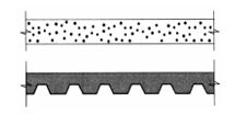
| Assembly Number | Description[2] [3] [4] | Fire-Resistance Rating[5] [6] [7] [8] | Typical Sound Transmission Class[5] [6] [7] [9] [10] [11] (STC) | Typical Impact Insulation Class[5] [9] [12] (IIC) |
|---|---|---|---|---|
| F1a | 90 mm reinforced concrete with 20 mm minimum cover over reinforcing steel | 1 h | 47 | 23 |
| F1b | 130 mm reinforced concrete with 25 mm minimum cover over reinforcing steel | 2 h | 52 | 27 |
| F1c | pre-stressed hollow core slab 200 mm deep with 25 mm minimum cover over reinforcing steel | 1 h | 50 | 28 |
| F1d | 150 mm composite slab on 75 mm steel deck with 152 x 152 x MW3.8 x MW3.8 wire mesh | N/A | 51 | 21 |
| F1e | F1 with
| 1.5 h | 57 | 36 |
| Column 2 | 3 | 4 | 5 | 6 |
Type of Assembly
Open Web Steel Joists
Assembly Number: F2
open web steel joists with concrete floor
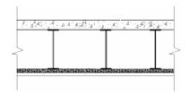
| Assembly Number | Description[2] [3] [4] | Fire-Resistance Rating[5] [6] [7] [8] | Typical Sound Transmission Class[5] [6] [7] [9] [10] [11] (STC) | Typical Impact Insulation Class[5] [9] [12] (IIC) |
|---|---|---|---|---|
| F2a | F2 with
| 45 min | 53 | 27 |
| F2b | F2 with
| 1.5 h | 53 | 28 |
| Column 2 | 3 | 4 | 5 | 6 |
Type of Assembly
Wood Floor Joists[13]
Assembly Number: F3[14]
- subfloor of 15.5 mm plywood, OSB or waferboard, or 17 mm tongue and groove lumber
- on wood joists or wood I-joists spaced not more than 610 mm o.c.
- with or without absorptive material in cavity
- 1 layer of gypsum board on ceiling side
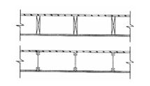
| Assembly Number | Description[2] [3] [4] | Fire-Resistance Rating[5] [6] [7] [8] | Typical Sound Transmission Class[5] [6] [7] [9] [10] [11] (STC) | Typical Impact Insulation Class[5] [9] [12] (IIC) |
|---|---|---|---|---|
| F3a | F3 with
| N/A | 29 | 27 |
| F3b | F3 with
| N/A | 31 | 30 |
| F3c | F3 with
| N/A | 27 | 26 |
| F3d | F3 with
| N/A | 29 | 29 |
| F3e | F3 with
| N/A | 27 | 25 |
| F3f | F3 with
| N/A | 29 | 28 |
| Column 2 | 3 | 4 | 5 | 6 |
Type of Assembly
Wood Floor Joists[13]
Assembly Number: F4[14]
- subfloor of 15.5 mm plywood, OSB or waferboard, or 17 mm tongue and groove lumber
- on wood joists or wood I-joists spaced not more than 610 mm o.c.
- with or without absorptive material in cavity
- 2 layers of gypsum board on ceiling side
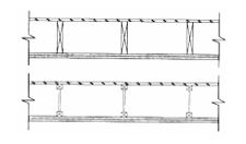
| Assembly Number | Description[2] [3] [4] | Fire-Resistance Rating[5] [6] [7] [8] | Typical Sound Transmission Class[5] [6] [7] [9] [10] [11] (STC) | Typical Impact Insulation Class[5] [9] [12] (IIC) |
|---|---|---|---|---|
| F4a | F4 with
| 1 h | 33 | 31 |
| F4b | F4 with
| 1 h | 34 | 31 |
| F4c | F4 with
| 45 min [1 h][15] | 35 | 34 |
| F4d | F4 with
| 45 min | 38 | 34 |
| F4e | F4 with
| 1 h | 32 | 30 |
| F4f | F4 with
| 45 min | 33 | 30 |
| F4g | F4 with
| 45 min | 34 | 33 |
| F4h | F4 with
| N/A | 35 | 33 |
| F4i | F4 with
| N/A | 31 | 30 |
| F4j | F4 with
| N/A | 33 | 33 |
| Column 2 | 3 | 4 | 5 | 6 |
Type of Assembly
Wood Floor Joists[13]
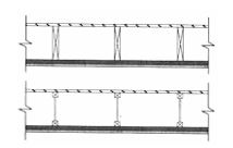
Assembly Number: F5[14]
- subfloor of 15.5 mm plywood, OSB or waferboard, or 17 mm tongue and groove lumber
- on wood joists or wood I-joists spaced not more than 610 mm o.c.
- with or without absorptive material in cavity
- steel furring channels spaced 406 mm or 610 mm o.c.
- 1 layer of gypsum board on ceiling side
| Assembly Number | Description[2] [3] [4] | Fire-Resistance Rating[5] [6] [7] [8] | Typical Sound Transmission Class[5] [6] [7] [9] [10] [11] (STC) | Typical Impact Insulation Class[5] [9] [12] (IIC) |
|---|---|---|---|---|
| F5a | F5 with
| 30 min | 35 | 37 |
| F5b | F5 with
| 30 min | 37 | 30 |
| F5c | F5 with
| 30 min [45 min][16] | 38 | 30 |
| F5d | F5 with
| 30 min | 40 | 33 |
| F5e | F5 with
| 30 min | 33 | 26 |
| F5f | F5 with
| 30 min | 35 | 29 |
| F5g | F5 with
| 30 min [45 min][16] | 36 | 29 |
| F5h | F5 with
| 30 min | 38 | 32 |
| F5i | F5 with
| < 30 min | 33 | 25 |
| F5j | F5 with
| < 30 min | 35 | 28 |
| F5k | F5 with
| < 30 min | 36 | 28 |
| F5l | F5 with
| < 30 min | 38 | 33 |
| Column 2 | 3 | 4 | 5 | 6 |
Type of Assembly
Wood Floor Joists[13]
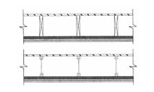
Assembly Number: F6[14]
- subfloor of 15.5 mm plywood, OSB or waferboard, or 17 mm tongue and groove lumber
- on wood joists or wood I-joists spaced not more than 610 mm o.c.
- with or without absorptive material in cavity
- steel furring channels spaced 406 mm or 610 mm o.c.
- 2 layers of gypsum board on ceiling side
| Assembly Number | Description[2] [3] [4] | Fire-Resistance Rating[5] [6] [7] [8] | Typical Sound Transmission Class[5] [6] [7] [9] [10] [11] (STC) | Typical Impact Insulation Class[5] [9] [12] (IIC) |
|---|---|---|---|---|
| F6a[17] | F6 with
| 1 h | 39 | 32 |
| F6b[17] | F6 with
| 1 h | 41 | 32 |
| F6c[17] | F6 with
| 1 h | 42 | 35 |
| F6d[17] | F6 with
| 1 h | 44 | 37 |
| F6e[17] | F6 with
| 1 h | 38 | 30 |
| F6f[17] | F6 with
| 1 h | 40 | 33 |
| F6g[17] | F6 with
| 1 h | 41 | 33 |
| F6h[17] | F6 with
| 45 min [1 h][18] | 43 | 36 |
| F6i | F6 with
| N/A | 37 | 30 |
| F6j | F6 with
| N/A | 39 | 33 |
| F6k | F6 with
| N/A | 40 | 33 |
| F6l | F6 with
| N/A | 42 | 36 |
| Column 2 | 3 | 4 | 5 | 6 |
Type of Assembly
Wood Floor Joists[13]
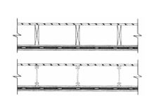
Assembly Number: F7[14]
- subfloor of 15.5 mm plywood, OSB or waferboard, or 17 mm tongue and groove lumber
- on wood joists or wood I-joists spaced not more than 610 mm o.c.
- with or without absorptive material in cavity
- 1 layer of gypsum board attached directly to joists on ceiling side
- resilient metal channels spaced 406 mm or 610 mm o.c. attached to joists through gypsum board
- 1 layer of gypsum board attached to resilient channels
| Assembly Number | Description[2] [3] [4] | Fire-Resistance Rating[5] [6] [7] [8] | Typical Sound Transmission Class[5] [6] [7] [9] [10] [11] (STC) | Typical Impact Insulation Class[5] [9] [12] (IIC) |
|---|---|---|---|---|
| F7a[17] | F7 with
| 1 h | 35 | 27 |
| F7b[17] | F7 with
| 1 h | 37 | 30 |
| F7c[17] | F7 with
| 1 h | 35 | 27 |
| F7d[17] | F7 with
| 1 h | 37 | 30 |
| F7e | F7 with
| N/A | 32 | 26 |
| F7f | F7 with
| N/A | 35 | 28 |
| Column 2 | 3 | 4 | 5 | 6 |
Type of Assembly
Wood Floor Joists[13]
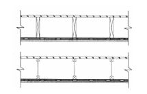
Assembly Number: F8[14]
- subfloor of 15.5 mm plywood, OSB or waferboard, or 17 mm tongue and groove lumber
- on wood joists or wood I-joists spaced not more than 610 mm o.c.
- with or without absorptive material in cavity
- resilient metal channels spaced 406 mm or 610 mm o.c.
- 1 layer of gypsum board on ceiling side
| Assembly Number | Description[2] [3] [4] | Fire-Resistance Rating[5] [6] [7] [8] | Typical Sound Transmission Class[5] [6] [7] [9] [10] [11] (STC) | Typical Impact Insulation Class[5] [9] [12] (IIC) |
|---|---|---|---|---|
| F8a | F8 with
| 30 min | 41 | 33 |
| F8b | F8 with
| 30 min | 43 | 36 |
| F8c | F8 with
| 30 min [45 min][16] | 48 | 41 |
| F8d | F8 with
| 30 min | 50 | 44 |
| F8e | F8 with
| 30 min | 39 | 32 |
| F8f | F8 with
| 30 min | 41 | 35 |
| F8g | F8 with
| 30 min [45 min][16] | 46 | 40 |
| F8h | F8 with
| 30 min | 48 | 43 |
| F8i | F8 with
| < 30 min | 41 | 31 |
| F8j | F8 with
| < 30 min | 41 | 34 |
| F8k | F8 with
| < 30 min | 46 | 39 |
| F8l | F8 with
| < 30 min | 48 | 42 |
| Column 2 | 3 | 4 | 5 | 6 |
Type of Assembly
Wood Floor Joists[13]
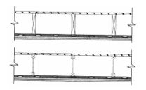
Assembly Number: F9[14]
- subfloor of 15.5 mm plywood, OSB or waferboard, or 17 mm tongue and groove lumber
- on wood joists or wood I-joists spaced not more than 610 mm o.c.
- with or without absorptive material in cavity
- resilient metal channels spaced 406 mm or 610 mm o.c.
- 2 layers of gypsum board on ceiling side
| Assembly Number | Description[2] [3] [4] | Fire-Resistance Rating[5] [6] [7] [8] | Typical Sound Transmission Class[5] [6] [7] [9] [10] [11] (STC) | Typical Impact Insulation Class[5] [9] [12] (IIC) |
|---|---|---|---|---|
| F9a[17] | F9 with
| 1 h | 45 | 38 |
| F9b[17] | F9 with
| 1 h | 47 | 40 |
| F9c[17] | F9 with
| 1 h [1.5 h][19] | 52 [54][19] | 46 |
| F9d[17] | F9 with
| 1 h [1.5 h][19] | 54 [56][19] | 48 |
| F9e[17] | F9 with
| 1 h | 44 | 36 |
| F9f[17] | F9 with
| 1 h | 46 | 39 |
| F9g[17] | F9 with
| 1 h [1.5 h][19] | 51 [53][19] | 44 |
| F9h[17] | F9 with
| 45 min [1 h][18] | 53 | 47 |
| F9i | F9 with
| N/A | 43 | 36 |
| F9j | F9 with
| N/A | 45 | 39 |
| F9k | F9 with
| N/A | 50 | 44 |
| F9l | F9 with
| N/A | 52 | 47 |
| Column 2 | 3 | 4 | 5 | 6 |
Type of Assembly
Wood Floor Joists[13]
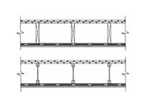
Assembly Number: F10[14]
- one subfloor layer of 11 mm sanded plywood, or OSB or waferboard
- one subfloor layer of 15.5 mm plywood, OSB or waferboard, or 17 mm tongue and groove lumber
- on wood joists or wood I-joists spaced not more than 610 mm o.c.
- with or without absorptive material in cavity
- resilient metal channels spaced 305 mm, 406 mm or 610 mm o.c.
- 1 layer of gypsum board on ceiling side
| Assembly Number | Description[2] [3] [4] | Fire-Resistance Rating[5] [6] [7] [8] | Typical Sound Transmission Class[5] [6] [7] [9] [10] [11] (STC) | Typical Impact Insulation Class[5] [9] [12] (IIC) |
|---|---|---|---|---|
| F10a | F10 with
| 30 min | 44 | 34 |
| F10b | F10 with
| 30 min | 46 | 37 |
| F10c | F10 with
| 30 min [45 min][18] | 51 | 42 |
| F10d | F10 with
| 30 min [45 min][16] | 53 | 45 |
| F10e | F10 with
| 1 h[20] | 53[20] | 44 |
| F10f[21] | F10 with
| 1 h[20] | 52[20] | 43 |
| F10g | F10 with
| 30 min | 42 | 33 |
| F10h | F10 with
| 30 min | 44 | 36 |
| F10i | F10 with
| 30 min [45 min][18] | 49 | 41 |
| F10j | F10 with
| 30 min [45 min][16] | 51 | 44 |
| F10k | F10 with
| N/A | 42 | 33 |
| F10l | F10 with
| N/A | 44 | 35 |
| F10m | F10 with
| N/A | 49 | 41 |
| F10n | F10 with
| N/A | 51 | 43 |
| Column 2 | 3 | 4 | 5 | 6 |
Type of Assembly
Wood Floor Joists[13]
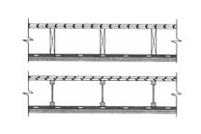
Assembly Number: F11[14]
- one subfloor layer of 11 mm sanded plywood, or OSB or waferboard
- one subfloor layer of 15.5 mm plywood, OSB or waferboard, or 17 mm tongue and groove lumber
- on wood joists or wood I-joists spaced not more than 610 mm o.c.
- with or without absorptive material in cavity
- resilient metal channels spaced 406 mm or 610 mm o.c.
- 2 layers of gypsum board on ceiling side
| Assembly Number | Description[2] [3] [4] | Fire-Resistance Rating[5] [6] [7] [8] | Typical Sound Transmission Class[5] [6] [7] [9] [10] [11] (STC) | Typical Impact Insulation Class[5] [9] [12] (IIC) |
|---|---|---|---|---|
| F11a[17] | F11 with
| 1 h | 48 | 39 |
| F11b[17] | F11 with
| 1 h | 50 | 42 |
| F11c[17] | F11 with
| 1 h [1.5 h][19] | 55 [56][19] | 47 |
| F11d[17] | F11 with
| 1 h [1.5 h][19] | 57 [58][19] | 50 |
| F11e[17] | F11 with
| 1.5 h[22] | 56[22] | 47 |
| F11f[21] | F11 with
| 1.5 h[22] | 56[22] | 46 |
| F11g[17] | F11 with
| 1 h | 47 | 38 |
| F11h[17] | F11 with
| 1 h | 49 | 40 |
| F11i[17] | F11 with
| 1 h [1.5 h][19] | 54 [55][19] | 46 |
| F11j[17] | F11 with
| 45 min [1 h][18] | 56 | 48 |
| F11k | F11 with
| N/A | 46 | 37 |
| F11l | F11 with
| N/A | 48 | 40 |
| F11m | F11 with
| N/A | 53 | 45 |
| F11n | F11 with
| N/A | 55 | 48 |
| Column 2 | 3 | 4 | 5 | 6 |
Type of Assembly
Wood Floor Joists[13]
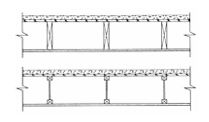
Assembly Number: F12[14]
- 25 mm gypsum-concrete topping (at least 44 kg/m2)
- subfloor of 15.5 mm plywood, OSB or waferboard, or 17 mm tongue and groove lumber
- on wood joists or wood I-joists spaced not more than 610 mm o.c.
- with or without absorptive material in cavity
- 1 layer of gypsum board on ceiling side
| Assembly Number | Description[2] [3] [4] | Fire-Resistance Rating[5] [6] [7] [8] | Typical Sound Transmission Class[5] [6] [7] [9] [10] [11] (STC) | Typical Impact Insulation Class[5] [9] [12] (IIC) |
|---|---|---|---|---|
| F12a | F12 with
| N/A | 41 | 13 |
| F12b | F12 with
| N/A | 43 | 16 |
| F12c | F12 with
| N/A | 39 | 12 |
| F12d | F12 with
| N/A | 41 | 15 |
| F12e | F12 with
| N/A | 39 | 12 |
| F12f | F12 with
| N/A | 41 | 15 |
| Column 2 | 3 | 4 | 5 | 6 |
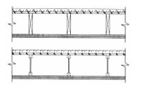
Type of Assembly
Wood Floor Joists[13]
Assembly Number: F13[14]
- 25 mm gypsum-concrete topping (at least 44 kg/m2)
- subfloor of 15.5 mm plywood, OSB or waferboard, or 17 mm tongue and groove lumber
- on wood joists or wood I-joists spaced not more than 610 mm o.c.
- with or without absorptive material in cavity
- 2 layers of gypsum board on ceiling side
| Assembly Number | Description[2] [3] [4] | Fire-Resistance Rating[5] [6] [7] [8] | Typical Sound Transmission Class[5] [6] [7] [9] [10] [11] (STC) | Typical Impact Insulation Class[5] [9] [12] (IIC) |
|---|---|---|---|---|
| F13a | F13 with
| 1 h | 43 | 16 |
| F13b | F13 with
| 1 h | 45 | 16 |
| F13c | F13 with
| 45 min [1 h][15] | 45 | 19 |
| F13d | F13 with
| 45 min | 47 | 19 |
| F13e | F13 with
| 1 h | 42 | 15 |
| F13f | F13 with
| 45 min | 44 | 15 |
| F13g | F13 with
| 45 min | 44 | 18 |
| F13h | F13 with
| N/A | 46 | 18 |
| F13i | F13 with
| N/A | 41 | 14 |
| F13j | F13 with
| N/A | 45 | 14 |
| Column 2 | 3 | 4 | 5 | 6 |
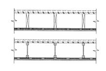
Type of Assembly
Wood Floor Joists[13]
Assembly Number: F14[14]
- 25 mm gypsum-concrete topping (at least 44 kg/m2)
- subfloor of 15.5 mm plywood, OSB or waferboard, or 17 mm tongue and groove lumber
- on wood joists or wood I-joists spaced not more than 610 mm o.c.
- with or without absorptive material in cavity
- resilient metal channels spaced 305 mm, 406 mm or 610 mm o.c.
- 1 layer of gypsum board on ceiling side
| Assembly Number | Description[2] [3] [4] | Fire-Resistance Rating[5] [6] [7] [8] | Typical Sound Transmission Class[5] [6] [7] [9] [10] [11] (STC) | Typical Impact Insulation Class[5] [9] [12] (IIC) |
|---|---|---|---|---|
| F14a | F14 with
| N/A | 53 | 22 |
| F14b | F14 with
| N/A | 55 | 22 |
| F14c | F14 with
| 30 min [45 min][18] | 60 | 30 |
| F14d | F14 with
| N/A | 62 | 30 |
| F14e | F14 with
| 1 h[20] | 60[20] | 31 |
| F14f[21] | F14 with
| 1 h[20] | 61[20] | 31 |
| F14g | F14 with
| N/A | 51 | 21 |
| F14h | F14 with
| N/A | 53 | 21 |
| F14i | F14 with
| N/A | 58 | 29 |
| F14j | F14 with
| N/A | 60 | 29 |
| F14k | F14 with
| N/A | 51 | 21 |
| F14l | F14 with
| N/A | 53 | 21 |
| F14m | F14 with
| N/A | 58 | 29 |
| F14n | F14 with
| N/A | 60 | 29 |
| Column 2 | 3 | 4 | 5 | 6 |
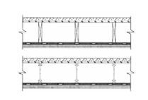
Type of Assembly
Wood Floor Joists[13]
Assembly Number: F15[14]
- 25 mm gypsum-concrete topping (at least 44 kg/m2)
- subfloor of 15.5 mm plywood, OSB or waferboard, or 17 mm tongue and groove lumber
- on wood joists or wood I-joists spaced not more than 610 mm o.c.
- with or without absorptive material in cavity
- resilient metal channels spaced 406 mm or 610 mm o.c.
- 2 layers of gypsum board on ceiling side
| Assembly Number | Description[2] [3] [4] | Fire-Resistance Rating[5] [6] [7] [8] | Typical Sound Transmission Class[5] [6] [7] [9] [10] [11] (STC) | Typical Impact Insulation Class[5] [9] [12] (IIC) |
|---|---|---|---|---|
| F15a[17] | F15 with
| 1 h[23] | 57 | 25 |
| F15b[17] | F15 with
| 1 h | 59 | 25 |
| F15c[17] | F15 with
| 1 h [1.5 h][19] | 64 [65][19] | 33 |
| F15d[17] | F15 with
| 1 h [1.5 h][19] | 66 [67][19] | 33 |
| F15e[17] | F15 with
| 1.5 h[22] | 65[22] | 33 |
| F15f[21] | F15 with
| 1.5 h[22] | 64[22] | 33 |
| F15g[17] | F15 with
| 1 h | 56 | 24 |
| F15h[17] | F15 with
| 1 h | 58 | 24 |
| F15i[17] | F15 with
| 1 h [1.5 h][19] | 63 [64][19] | 32 |
| F15j[17] | F15 with
| 45 min [1 h][18] | 65 | 32 |
| F15k | F15 with
| N/A | 55 | 23 |
| F15l | F15 with
| N/A | 57 | 23 |
| F15m | F15 with
| N/A | 62 | 31 |
| F15n | F15 with
| N/A | 64 | 31 |
| Column 2 | 3 | 4 | 5 | 6 |
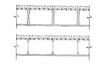
Type of Assembly
Wood Floor Joists[13]
Assembly Number: F16[14]
- 38 mm concrete topping (at least 70 kg/m2)
- subfloor of 15.5 mm plywood, OSB or waferboard, or 17 mm tongue and groove lumber
- on wood joists or wood I-joists spaced not more than 610 mm o.c.
- with or without absorptive material in cavity
- 1 layer of gypsum board on ceiling side
| Assembly Number | Description[2] [3] [4] | Fire-Resistance Rating[5] [6] [7] [8] | Typical Sound Transmission Class[5] [6] [7] [9] [10] [11] (STC) | Typical Impact Insulation Class[5] [9] [12] (IIC) |
|---|---|---|---|---|
| F16a | F16 with
| N/A | 44 | 22 |
| F16b | F16 with
| N/A | 46 | 25 |
| F16c | F16 with
| N/A | 43 | 21 |
| F16d | F16 with
| N/A | 45 | 24 |
| F16e | F16 with
| N/A | 42 | 21 |
| F16f | F16 with
| N/A | 44 | 24 |
| Column 2 | 3 | 4 | 5 | 6 |
Type of Assembly
Wood Floor Joists[13]
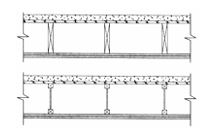
Assembly Number: F17[14]
- 38 mm concrete topping (at least 70 kg/m2)
- subfloor of 15.5 mm plywood, OSB or waferboard, or 17 mm tongue and groove lumber
- on wood joists or wood I-joists spaced not more than 610 mm o.c.
- with or without absorptive material in cavity
- 2 layers of gypsum board on ceiling side
| Assembly Number | Description[2] [3] [4] | Fire-Resistance Rating[5] [6] [7] [8] | Typical Sound Transmission Class[5] [6] [7] [9] [10] [11] (STC) | Typical Impact Insulation Class[5] [9] [12] (IIC) |
|---|---|---|---|---|
| F17a | F17 with
| 1 h | 48 | 24 |
| F17b | F17 with
| 1 h | 51 | 24 |
| F17c | F17 with
| 45 min [1 h][15] | 48 | 27 |
| F17d | F17 with
| 45 min | 51 | 27 |
| F17e | F17 with
| 1 h | 47 | 23 |
| F17f | F17 with
| 45 min | 48 | 23 |
| F17g | F17 with
| 45 min | 49 | 26 |
| F17h | F17 with
| N/A | 50 | 26 |
| F17i | F17 with
| N/A | 47 | 23 |
| F17j | F17 with
| N/A | 49 | 26 |
| Column 2 | 3 | 4 | 5 | 6 |
Type of Assembly
Wood Floor Joists[13]
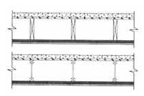
Assembly Number: F18[14]
- 38 mm concrete topping (at least 70 kg/m2)
- subfloor of 15.5 mm plywood, OSB or waferboard, or 17 mm tongue and groove lumber
- on wood joists or wood I-joists spaced not more than 610 mm o.c.
- with or without absorptive material in cavity
- steel furring channels spaced 406 mm or 610 mm o.c.
- 1 layer of gypsum board on ceiling side
| Assembly Number | Description[2] [3] [4] | Fire-Resistance Rating[5] [6] [7] [8] | Typical Sound Transmission Class[5] [6] [7] [9] [10] [11] (STC) | Typical Impact Insulation Class[5] [9] [12] (IIC) |
|---|---|---|---|---|
| F18a | F18 with
| N/A | 50 | 25 |
| F18b | F18 with
| N/A | 52 | 25 |
| F18c | F18 with
| N/A | 53 | 28 |
| F18d | F18 with
| N/A | 55 | 28 |
| F18e | F18 with
| N/A | 49 | 24 |
| F18f | F18 with
| N/A | 51 | 24 |
| F18g | F18 with
| N/A | 52 | 27 |
| F18h | F18 with
| N/A | 54 | 27 |
| F18i | F18 with
| N/A | 48 | 24 |
| F18j | F18 with
| N/A | 50 | 24 |
| F18k | F18 with
| N/A | 51 | 27 |
| F18l | F18 with
| N/A | 53 | 27 |
| Column 2 | 3 | 4 | 5 | 6 |
Type of Assembly
Wood Floor Joists[13]
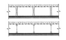
Assembly Number: F19[14]
- 38 mm concrete topping (at least 70 kg/m2)
- subfloor of 15.5 mm plywood, OSB or waferboard, or 17 mm tongue and groove lumber
- on wood joists or wood I-joists spaced not more than 610 mm o.c.
- with or without absorptive material in cavity
- steel furring channels spaced 406 mm or 610 mm o.c.
- 2 layers of gypsum board on ceiling side
| Assembly Number | Description[2] [3] [4] | Fire-Resistance Rating[5] [6] [7] [8] | Typical Sound Transmission Class[5] [6] [7] [9] [10] [11] (STC) | Typical Impact Insulation Class[5] [9] [12] (IIC) |
|---|---|---|---|---|
| F19a[17] | F19 with
| 1 h | 54 | 27 |
| F19b[17] | F19 with
| 1 h | 56 | 27 |
| F19c[17] | F19 with
| 1 h | 57 | 30 |
| F19d[17] | F19 with
| 1 h | 59 | 30 |
| F19e[17] | F19 with
| 1 h | 53 | 26 |
| F19f[17] | F19 with
| 1 h | 55 | 26 |
| F19g[17] | F19 with
| 1 h | 56 | 29 |
| F19h[17] | F19 with
| 1 h | 58 | 29 |
| F19i | F19 with
| N/A | 53 | 26 |
| F19j | F19 with
| N/A | 55 | 26 |
| F19k | F19 with
| N/A | 56 | 29 |
| F19l | F19 with
| N/A | 58 | 29 |
| Column 2 | 3 | 4 | 5 | 6 |
Type of Assembly
Wood Floor Joists[13]
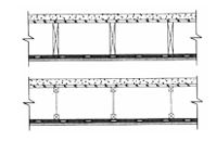
Assembly Number: F20[14]
- 38 mm concrete topping (at least 70 kg/m2)
- subfloor of 15.5 mm plywood, OSB or waferboard, or 17 mm tongue and groove lumber
- on wood joists or wood I-joists spaced not more than 610 mm o.c.
- with or without absorptive material in cavity
- resilient metal channels spaced 305 mm, 406 mm or 610 mm o.c.
- 1 layer of gypsum board on ceiling side
| Assembly Number | Description[2] [3] [4] | Fire-Resistance Rating[5] [6] [7] [8] | Typical Sound Transmission Class[5] [6] [7] [9] [10] [11] (STC) | Typical Impact Insulation Class[5] [9] [12] (IIC) |
|---|---|---|---|---|
| F20a | F20 with
| [45 min][23] | 56 | 31 |
| F20b | F20 with
| N/A | 58 | 31 |
| F20c | F20 with
| 30 min [45 min][18] [23] | 63 | 39 |
| F20d | F20 with
| N/A | 65 | 39 |
| F20e | F20 with
| 1 h[20] | 64[20] | 40 |
| F20f[21] | F20 with
| 1 h[20] | 65[20] | 40 |
| F20g | F20 with
| N/A | 55 | 30 |
| F20h | F20 with
| N/A | 57 | 30 |
| F20i | F20 with
| N/A | 62 | 38 |
| F20j | F20 with
| N/A | 64 | 38 |
| F20k | F20 with
| N/A | 54 | 30 |
| F20l | F20 with
| N/A | 56 | 30 |
| F20m | F20 with
| N/A | 61 | 38 |
| F20n | F20 with
| N/A | 63 | 38 |
| Column 2 | 3 | 4 | 5 | 6 |
Type of Assembly
Wood Floor Joists[13]
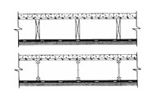
Assembly Number: F21[14]
- 38 mm concrete topping (at least 70 kg/m2)
- subfloor of 15.5 mm plywood, OSB or waferboard, or 17 mm tongue and groove lumber
- on wood joists or wood I-joists spaced not more than 610 mm o.c.
- with or without absorptive material in cavity
- resilient metal channels spaced 305 mm, 406 mm or 610 mm o.c.
- 2 layers of gypsum board on ceiling side
| Assembly Number | Description[2] [3] [4] | Fire-Resistance Rating[5] [6] [7] [8] | Typical Sound Transmission Class[5] [6] [7] [9] [10] [11] (STC) | Typical Impact Insulation Class[5] [9] [12] (IIC) |
|---|---|---|---|---|
| F21a[17] | F21 with
| 1 h | 60 | 33 |
| F21b[17] | F21 with
| 1 h | 62 | 33 |
| F21c[17] | F21 with
| 1 h [1.5 h][19] | 67 [68][19] | 41 [42][19] |
| F21d[17] | F21 with
| 1 h [1.5 h][19] | 69 [70][19] | 41 [42][19] |
| F21e[17] | F21 with
| [1.5 h][22] | 68[22] | 42 |
| F21f[21] | F21 with
| [1.5 h][22] | 68[22] | 42 |
| F21g[17] | F21 with
| 1 h | 59 | 32 |
| F21h[17] | F21 with
| 1 h | 61 | 32 |
| F21i[17] | F21 with
| 1 h [1.5 h][19] | 66 [67][19] | 40 |
| F21j[17] | F21 with
| 1 h | 68 | 40 |
| F21k | F21 with
| N/A | 59 | 32 |
| F21l | F21 with
| N/A | 61 | 32 |
| F21m | F21 with
| N/A | 66 | 40 |
| F21n | F21 with
| N/A | 68 | 40 |
| Column 2 | 3 | 4 | 5 | 6 |
Type of Assembly
Wood Floor Trusses[24]
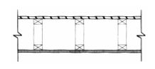
Assembly Number: F22
- subfloor of 15.5 mm plywood, OSB or waferboard, or 17 mm tongue and groove lumber
- on wood trusses spaced not more than 610 mm o.c.
- with or without absorptive material in cavity
- 1 layer of gypsum board on ceiling side
| Assembly Number | Description[2] [3] [4] | Fire-Resistance Rating[5] [6] [7] [8] | Typical Sound Transmission Class[5] [6] [7] [9] [10] [11] (STC) | Typical Impact Insulation Class[5] [9] [12] (IIC) |
|---|---|---|---|---|
| F22a | F22 with
| N/A | 29 | 27 |
| F22b | F22 with
| N/A | 31 | 30 |
| F22c | F22 with
| N/A | 28 | 26 |
| F22d | F22 with
| N/A | 30 | 29 |
| F22e | F22 with
| N/A | 27 | 25 |
| F22f | F22 with
| N/A | 31 | 28 |
| Column 2 | 3 | 4 | 5 | 6 |
Type of Assembly
Wood Floor Trusses[24]
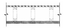
Assembly Number: F23
- subfloor of 15.5 mm plywood, OSB or waferboard, or 17 mm tongue and groove lumber
- on wood trusses spaced not more than 610 mm o.c.
- with or without absorptive material in cavity
- 2 layers of gypsum board on ceiling side
| Assembly Number | Description[2] [3] [4] | Fire-Resistance Rating[5] [6] [7] [8] | Typical Sound Transmission Class[5] [6] [7] [9] [10] [11] (STC) | Typical Impact Insulation Class[5] [9] [12] (IIC) |
|---|---|---|---|---|
| F23a | F23 with
| 1 h | 34 | 31 |
| F23b | F23 with
| 1 h | 35 | 31 |
| F23c | F23 with
| 45 min [1 h][15] | 36 | 34 |
| F23d | F23 with
| 45 min | 37 | 34 |
| F23e | F23 with
| 1 h | 32 | 30 |
| F23f | F23 with
| 45 min | 33 | 30 |
| F23g | F23 with
| N/A | 34 | 33 |
| F23h | F23 with
| N/A | 32 | 30 |
| F23i | F23 with
| N/A | 34 | 33 |
| Column 2 | 3 | 4 | 5 | 6 |
Type of Assembly
Wood Floor Trusses[24]
Assembly Number: F24
- subfloor of 15.5 mm plywood, OSB or waferboard, or 17 mm tongue and groove lumber
- on wood trusses spaced not more than 610 mm o.c.
- with or without absorptive material in cavity
- steel furring channels spaced 406 mm or 610 mm o.c.
- 1 layer of gypsum board on ceiling side
| Assembly Number | Description[2] [3] [4] | Fire-Resistance Rating[5] [6] [7] [8] | Typical Sound Transmission Class[5] [6] [7] [9] [10] [11] (STC) | Typical Impact Insulation Class[5] [9] [12] (IIC) |
|---|---|---|---|---|
| F24a | F24 with
| N/A | 35 | 27 |
| F24b | F24 with
| N/A | 37 | 30 |
| F24c | F24 with
| N/A | 38 | 30 |
| F24d | F24 with
| N/A | 40 | 33 |
| F24e | F24 with
| N/A | 33 | 26 |
| F24f | F24 with
| N/A | 36 | 29 |
| F24g | F24 with
| N/A | 37 | 29 |
| F24h | F24 with
| N/A | 39 | 32 |
| F24i | F24 with
| N/A | 33 | 25 |
| F24j | F24 with
| N/A | 35 | 28 |
| F24k | F24 with
| N/A | 36 | 28 |
| F24l | F24 with
| N/A | 38 | 31 |
| Column 2 | 3 | 4 | 5 | 6 |
Type of Assembly
Wood Floor Trusses[24]
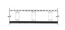
Assembly Number: F25
- subfloor of 15.5 mm plywood, OSB or waferboard, or 17 mm tongue and groove lumber
- on wood trusses spaced not more than 610 mm o.c.
- with or without absorptive material in cavity
- steel furring channels spaced 406 mm or 610 mm o.c.
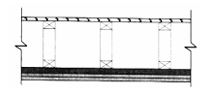
| Assembly Number | Description[2] [3] [4] | Fire-Resistance Rating[5] [6] [7] [8] | Typical Sound Transmission Class[5] [6] [7] [9] [10] [11] (STC) | Typical Impact Insulation Class[5] [9] [12] (IIC) |
|---|---|---|---|---|
| F25a | F25 with
| 1 h | 40 | 32 |
| F25b | F25 with
| 1 h | 42 | 34 |
| F25c | F25 with
| 1 h | 43 | 35 |
| F25d | F25 with
| 45 min [1 h][18] | 45 | 37 |
| F25e | F25 with
| 1 h | 38 | 30 |
| F25f | F25 with
| 1 h | 40 | 33 |
| F25g | F25 with
| 1 h | 41 | 33 |
| F25h | F25 with
| 45 min [1 h][18] | 43 | 36 |
| F25i | F25 with
| N/A | 38 | 30 |
| F25j | F25 with
| N/A | 40 | 33 |
| F25k | F25 with
| N/A | 41 | 33 |
| F25l | F25 with
| N/A | 43 | 36 |
| Column 2 | 3 | 4 | 5 | 6 |
Type of Assembly
Wood Floor Trusses[24]
Assembly Number: F26
- subfloor of 15.5 mm plywood, OSB or waferboard, or 17 mm tongue and groove lumber
- on wood trusses spaced not more than 610 mm o.c.
- with or without absorptive material in cavity
- 1 layer of gypsum board attached directly to trusses on ceiling side
- resilient metal channels spaced 406 mm or 610 mm o.c. attached to trusses through the gypsum board
- 1 layer of gypsum board attached to resilient metal channels
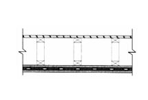
| Assembly Number | Description[2] [3] [4] | Fire-Resistance Rating[5] [6] [7] [8] | Typical Sound Transmission Class[5] [6] [7] [9] [10] [11] (STC) | Typical Impact Insulation Class[5] [9] [12] (IIC) |
|---|---|---|---|---|
| F26a | F26 with
| N/A | 35 | 27 |
| F26b | F26 with
| N/A | 37 | 30 |
| F26c | F26 with
| N/A | 35 | 27 |
| F26d | F26 with
| N/A | 37 | 30 |
| F26e | F26 with
| N/A | 32 | 26 |
| F26f | F26 with
| N/A | 35 | 28 |
| Column 2 | 3 | 4 | 5 | 6 |
Type of Assembly
Wood Floor Trusses[24]
Assembly Number: F27
- subfloor of 15.5 mm plywood, OSB or waferboard, or 17 mm tongue and groove lumber
- on wood trusses spaced not more than 610 mm o.c.
- with or without absorptive material in cavity
- resilient metal channels spaced 406 mm or 610 mm o.c.
- 1 layer of gypsum board on ceiling side
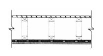
| Assembly Number | Description[2] [3] [4] | Fire-Resistance Rating[5] [6] [7] [8] | Typical Sound Transmission Class[5] [6] [7] [9] [10] [11] (STC) | Typical Impact Insulation Class[5] [9] [12] (IIC) |
|---|---|---|---|---|
| F27a | F27 with
| N/A | 41 | 33 |
| F27b | F27 with
| N/A | 43 | 36 |
| F27c | F27 with
| 30 min [45 min][25] | 48 | 41 |
| F27d | F27 with
| N/A | 50 | 44 |
| F27e | F27 with
| N/A | 40 | 32 |
| F27f | F27 with
| N/A | 42 | 35 |
| F27g | F27 with
| N/A | 47 | 40 |
| F27h | F27 with
| N/A | 49 | 43 |
| F27i | F27 with
| N/A | 39 | 31 |
| F27j | F27 with
| N/A | 41 | 34 |
| F27k | F27 with
| N/A | 46 | 39 |
| F27l | F27 with
| N/A | 48 | 42 |
| Column 2 | 3 | 4 | 5 | 6 |
Type of Assembly
Wood Floor Trusses[24]
Assembly Number: F28
- subfloor of 15.5 mm plywood, OSB or waferboard, or 17 mm tongue and groove lumber
- on wood trusses spaced not more than 610 mm o.c.
- with or without absorptive material in cavity
- resilient metal channels spaced 406 mm or 610 mm o.c.
- 2 layers of gypsum board on ceiling side
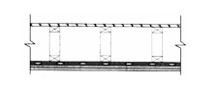
| Assembly Number | Description[2] [3] [4] | Fire-Resistance Rating[5] [6] [7] [8] | Typical Sound Transmission Class[5] [6] [7] [9] [10] [11] (STC) | Typical Impact Insulation Class[5] [9] [12] (IIC) |
|---|---|---|---|---|
| F28a | F28 with
| 1 h | 46 | 38 |
| F28b | F28 with
| 1 h | 48 | 40 |
| F28c | F28 with
| 1 h | 54 | 46 |
| F28d | F28 with
| 45 min [1 h][18] | 55 | 48 |
| F28e | F28 with
| 1 h | 44 | 36 |
| F28f | F28 with
| 1 h | 46 | 39 |
| F28g | F28 with
| 1 h | 51 | 44 |
| F28h | F28 with
| 45 min [1 h][18] | 53 | 47 |
| F28i | F28 with
| N/A | 44 | 36 |
| F28j | F28 with
| N/A | 46 | 39 |
| F28k | F28 with
| N/A | 51 | 44 |
| F28l | F28 with
| N/A | 53 | 47 |
| Column 2 | 3 | 4 | 5 | 6 |
Type of Assembly
Wood Floor Trusses[24]
Assembly Number: F29
- one subfloor layer of 11 mm sanded plywood, or OSB or waferboard
- one subfloor layer of 15.5 mm plywood, OSB or waferboard, or 17 mm tongue and groove lumber
- on wood trusses spaced not more than 610 mm o.c.
- with or without absorptive material in cavity
- resilient metal channels spaced 406 mm or 610 mm o.c.
- 1 layer of gypsum board on ceiling side
| Assembly Number | Description[2] [3] [4] | Fire-Resistance Rating[5] [6] [7] [8] | Typical Sound Transmission Class[5] [6] [7] [9] [10] [11] (STC) | Typical Impact Insulation Class[5] [9] [12] (IIC) |
|---|---|---|---|---|
| F29a | F29 with
| N/A | 44 | 35 |
| F29b | F29 with
| N/A | 46 | 37 |
| F29c | F29 with
| 30 min [45 min][25] | 51 | 43 |
| F29d | F29 with
| N/A | 53 | 45 |
| F29e | F29 with
| N/A | 43 | 33 |
| F29f | F29 with
| N/A | 45 | 36 |
| F29g | F29 with
| N/A | 50 | 41 |
| F29h | F29 with
| N/A | 52 | 44 |
| F29i | F29 with
| N/A | 42 | 34 |
| F29j | F29 with
| N/A | 44 | 36 |
| F29k | F29 with
| N/A | 49 | 41 |
| F29l | F29 with
| N/A | 51 | 44 |
| Column 2 | 3 | 4 | 5 | 6 |
Type of Assembly
Wood Floor Trusses[24]
Assembly Number: F30
- one subfloor layer of 11 mm sanded plywood, or OSB or waferboard
- one subfloor layer of 15.5 mm plywood, OSB or waferboard, or 17 mm tongue and groove lumber
- on wood trusses spaced not more than 610 mm o.c.
- with or without absorptive material in cavity
- resilient metal channels spaced 406 mm or 610 mm o.c.
- 2 layers of gypsum board on ceiling side
| Assembly Number | Description[2] [3] [4] | Fire-Resistance Rating[5] [6] [7] [8] | Typical Sound Transmission Class[5] [6] [7] [9] [10] [11] (STC) | Typical Impact Insulation Class[5] [9] [12] (IIC) |
|---|---|---|---|---|
| F30a | F30 with
| 1 h | 49 | 39 |
| F30b | F30 with
| 1 h | 51 | 42 |
| F30c | F30 with
| 1 h [1.5 h][26] | 56 [58][26] | 47 [50][26] |
| F30d | F30 with
| 45 min [1 h][18] | 58 | 50 |
| F30e | F30 with
| 1 h | 47 | 38 |
| F30f | F30 with
| 1 h | 49 | 40 |
| F30g | F30 with
| 1 h | 54 | 46 |
| F30h | F30 with
| 45 min [1 h][18] | 56 | 48 |
| F30i | F30 with
| N/A | 47 | 37 |
| F30j | F30 with
| N/A | 49 | 40 |
| F30k | F30 with
| N/A | 54 | 45 |
| F30l | F30 with
| N/A | 56 | 48 |
| Column 2 | 3 | 4 | 5 | 6 |
Type of Assembly
Wood Floor Trusses[24]
Assembly Number: F31
- 25 mm gypsum-concrete topping (at least 44 kg/m2)
- subfloor of 15.5 mm plywood, OSB or waferboard, or 17 mm tongue and groove lumber
- on wood trusses spaced not more than 610 mm o.c.
- with or without absorptive material in cavity
- 1 layer of gypsum board on ceiling side
| Assembly Number | Description[2] [3] [4] | Fire-Resistance Rating[5] [6] [7] [8] | Typical Sound Transmission Class[5] [6] [7] [9] [10] [11] (STC) | Typical Impact Insulation Class[5] [9] [12] (IIC) |
|---|---|---|---|---|
| F31a | F31 with
| N/A | 41 | 17 |
| F31b | F31 with
| N/A | 43 | 20 |
| F31c | F31 with
| N/A | 40 | 17 |
| F31d | F31 with
| N/A | 42 | 20 |
| F31e | F31 with
| N/A | 39 | 16 |
| F31f | F31 with
| N/A | 41 | 19 |
| Column 2 | 3 | 4 | 5 | 6 |
Type of Assembly
Wood Floor Trusses[24]
Assembly Number: F32
- 25 mm gypsum-concrete topping (at least 44 kg/m2)
- subfloor of 15.5 mm plywood, OSB or waferboard, or 17 mm tongue and groove lumber
- on wood trusses spaced not more than 610 mm o.c.
- with or without absorptive material in cavity
- 2 layers of gypsum board on ceiling side
| Assembly Number | Description[2] [3] [4] | Fire-Resistance Rating[5] [6] [7] [8] | Typical Sound Transmission Class[5] [6] [7] [9] [10] [11] (STC) | Typical Impact Insulation Class[5] [9] [12] (IIC) |
|---|---|---|---|---|
| F32a | F32 with
| 1 h | 46 | 20 |
| F32b | F32 with
| 1 h | 47 | 20 |
| F32c | F32 with
| 45 min [1 h][15] | 48 | 23 |
| F32d | F32 with
| 45 min | 49 | 23 |
| F32e | F32 with
| 1 h | 44 | 19 |
| F32f | F32 with
| 45 min | 45 | 19 |
| F32g | F32 with
| N/A | 46 | 19 |
| F32h | F32 with
| N/A | 44 | 19 |
| F32i | F32 with
| N/A | 46 | 22 |
| Column 2 | 3 | 4 | 5 | 6 |
Type of Assembly
Wood Floor Trusses[24]
Assembly Number: F33
- 25 mm gypsum-concrete topping (at least 44 kg/m2)
- subfloor of 15.5 mm plywood, OSB or waferboard, or 17 mm tongue and groove lumber
- on wood trusses spaced not more than 610 mm o.c.
- with or without absorptive material in cavity
- resilient metal channels spaced 406 mm or 610 mm o.c.
- 1 layer of gypsum board on ceiling side
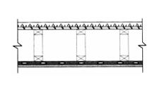
| Assembly Number | Description[2] [3] [4] | Fire-Resistance Rating[5] [6] [7] [8] | Typical Sound Transmission Class[5] [6] [7] [9] [10] [11] (STC) | Typical Impact Insulation Class[5] [9] [12] (IIC) |
|---|---|---|---|---|
| F33a | F33 with
| N/A | 53 | 26 |
| F33b | F33 with
| N/A | 55 | 26 |
| F33c | F33 with
| 30 min [45 min][25] | 60 | 34 |
| F33d | F33 with
| N/A | 62 | 34 |
| F33e | F33 with
| N/A | 52 | 26 |
| F33f | F33 with
| N/A | 54 | 26 |
| F33g | F33 with
| N/A | 59 | 34 |
| F33h | F33 with
| N/A | 61 | 34 |
| F33i | F33 with
| N/A | 51 | 25 |
| F33j | F33 with
| N/A | 53 | 25 |
| F33k | F33 with
| N/A | 58 | 33 |
| F33l | F33 with
| N/A | 60 | 33 |
| Column 2 | 3 | 4 | 5 | 6 |
Type of Assembly
Wood Floor Trusses[24]
Assembly Number: F34
- 25 mm gypsum-concrete topping (at least 44 kg/m2)
- subfloor of 15.5 mm plywood, OSB or waferboard, or 17 mm tongue and groove lumber
- on wood trusses spaced not more than 610 mm o.c.
- with or without absorptive material in cavity
- resilient metal channels spaced 406 mm or 610 mm o.c.
- 2 layers of gypsum board on ceiling side
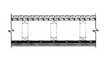
| Assembly Number | Description[2] [3] [4] | Fire-Resistance Rating[5] [6] [7] [8] | Typical Sound Transmission Class[5] [6] [7] [9] [10] [11] (STC) | Typical Impact Insulation Class[5] [9] [12] (IIC) |
|---|---|---|---|---|
| F34a | F34 with
| 1 h | 57 | 29 |
| F34b | F34 with
| 1 h | 60 | 29 |
| F34c | F34 with
| 1 h [1.5 h][26] | 65 [67][26] | 37 |
| F34d | F34 with
| 45 min [1 h][18] | 67 | 37 |
| F34e | F34 with
| 1 h | 56 | 28 |
| F34f | F34 with
| 1 h | 58 | 28 |
| F34g | F34 with
| 1 h | 63 | 36 |
| F34h | F34 with
| 45 min [1 h][18] | 65 | 36 |
| F34i | F34 with
| N/A | 56 | 28 |
| F34j | F34 with
| N/A | 58 | 28 |
| F34k | F34 with
| N/A | 63 | 36 |
| F34l | F34 with
| N/A | 65 | 36 |
| Column 2 | 3 | 4 | 5 | 6 |
Type of Assembly
Wood Floor Trusses[24]
Assembly Number: F35
- 38 mm concrete topping (at least 70 kg/m2)
- subfloor of 15.5 mm plywood, OSB or waferboard, or 17 mm tongue and groove lumber
- on wood trusses spaced not more than 610 mm o.c.
- with or without absorptive material in cavity
- 1 layer of gypsum board on ceiling side
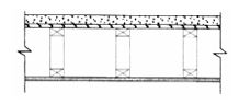
| Assembly Number | Description[2] [3] [4] | Fire-Resistance Rating[5] [6] [7] [8] | Typical Sound Transmission Class[5] [6] [7] [9] [10] [11] (STC) | Typical Impact Insulation Class[5] [9] [12] (IIC) |
|---|---|---|---|---|
| F35a | F35 with
| N/A | 45 | 26 |
| F35b | F35 with
| N/A | 47 | 29 |
| F35c | F35 with
| N/A | 43 | 26 |
| F35d | F35 with
| N/A | 45 | 29 |
| F35e | F35 with
| N/A | 43 | 26 |
| F35f | F35 with
| N/A | 45 | 29 |
| Column 2 | 3 | 4 | 5 | 6 |
Type of Assembly
Wood Floor Trusses[24]
Assembly Number: F36
- 38 mm concrete topping (at least 70 kg/m2)
- subfloor of 15.5 mm plywood, OSB or waferboard, or 17 mm tongue and groove lumber
- on wood trusses spaced not more than 610 mm o.c.
- with or without absorptive material in cavity
- 2 layers of gypsum board on ceiling side
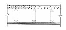
| Assembly Number | Description[2] [3] [4] | Fire-Resistance Rating[5] [6] [7] [8] | Typical Sound Transmission Class[5] [6] [7] [9] [10] [11] (STC) | Typical Impact Insulation Class[5] [9] [12] (IIC) |
|---|---|---|---|---|
| F36a | F36 with
| 1 h | 49 | 28 |
| F36b | F36 with
| 1 h | 50 | 28 |
| F36c | F36 with
| 45 min [1 h][15] | 51 | 31 |
| F36d | F36 with
| 45 min | 52 | 31 |
| F36e | F36 with
| 1 h | 48 | 27 |
| F36f | F36 with
| 45 min | 49 | 27 |
| F36g | F36 with
| N/A | 50 | 30 |
| F36h | F36 with
| N/A | 47 | 27 |
| F36i | F36 with
| N/A | 49 | 30 |
| Column 2 | 3 | 4 | 5 | 6 |
Type of Assembly
Wood Floor Trusses[24]
Assembly Number: F37
- 38 mm concrete topping (at least 70 kg/m2)
- subfloor of 15.5 mm plywood, OSB or waferboard, or 17 mm tongue and groove lumber
- on wood trusses spaced not more than 610 mm o.c.
- with or without absorptive material in cavity
- resilient metal channels spaced 406 mm or 610 mm o.c.
- 1 layer of gypsum board on ceiling side
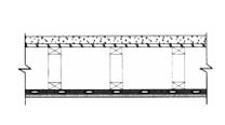
| Assembly Number | Description[2] [3] [4] | Fire-Resistance Rating[5] [6] [7] [8] | Typical Sound Transmission Class[5] [6] [7] [9] [10] [11] (STC) | Typical Impact Insulation Class[5] [9] [12] (IIC) |
|---|---|---|---|---|
| F37a | F37 with
| 45 min | 56 | 35 |
| F37b | F37 with
| N/A | 59 | 35 |
| F37c | F37 with
| 30 min [45 min][25] | 63 | 43 |
| F37d | F37 with
| N/A | 66 | 43 |
| F37e | F37 with
| N/A | 55 | 35 |
| F37f | F37 with
| N/A | 57 | 35 |
| F37g | F37 with
| N/A | 62 | 43 |
| F37h | F37 with
| N/A | 64 | 43 |
| F37i | F37 with
| N/A | 54 | 35 |
| F37j | F37 with
| N/A | 57 | 35 |
| F37k | F37 with
| N/A | 61 | 43 |
| F37l | F37 with
| N/A | 64 | 43 |
| Column 2 | 3 | 4 | 5 | 6 |
Type of Assembly
Wood Floor Trusses[24]
Assembly Number: F38
- 38 mm concrete topping (at least 70 kg/m2)
- subfloor of 15.5 mm plywood, OSB or waferboard, or 17 mm tongue and groove lumber
- on wood trusses spaced not more than 610 mm o.c.
- with or without absorptive material in cavity
- resilient metal channels spaced 406 mm or 610 mm o.c.
- 2 layers of gypsum board on ceiling side
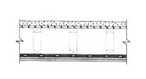
| Assembly Number | Description[2] [3] [4] | Fire-Resistance Rating[5] [6] [7] [8] | Typical Sound Transmission Class[5] [6] [7] [9] [10] [11] (STC) | Typical Impact Insulation Class[5] [9] [12] (IIC) |
|---|---|---|---|---|
| F38a | F38 with
| 1 h | 61 | 37 |
| F38b | F38 with
| 1 h | 63 | 37 |
| F38c | F38 with
| 1 h [1.5 h][26] | 69 [71][26] | 45 |
| F38d | F38 with
| 1 h | 70 | 45 |
| F38e | F38 with
| 1 h | 60 | 36 |
| F38f | F38 with
| 1 h | 62 | 36 |
| F38g | F38 with
| 1 h | 67 | 44 |
| F38h | F38 with
| 1 h | 69 | 44 |
| F38i | F38 with
| N/A | 59 | 36 |
| F38j | F38 with
| N/A | 61 | 36 |
| F38k | F38 with
| N/A | 66 | 44 |
| F38l | F38 with
| N/A | 68 | 44 |
| Column 2 | 3 | 4 | 5 | 6 |
Cold Formed Steel Floor Joists[27]
Type of Assembly
Cold Formed Steel Floor Joists[27]
Assembly Number: F39
- subfloor of 15.5 mm plywood, OSB or waferboard, or 17 mm tongue and groove lumber
- on steel joists spaced not more than 610 mm o.c.
- with or without absorptive material in cavity
- 1 layer of gypsum board on ceiling side
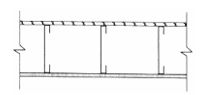
| Assembly Number | Description[2] [3] [4] | Fire-Resistance Rating[5] [6] [7] [8] | Typical Sound Transmission Class[5] [6] [7] [9] [10] [11] (STC) | Typical Impact Insulation Class[5] [9] [12] (IIC) |
|---|---|---|---|---|
| F39a | F39 with
| N/A | 29 | 27 |
| F39b | F39 with
| N/A | 31 | 30 |
| F39c | F39 with
| N/A | 27 | 26 |
| F39d | F39 with
| N/A | 29 | 29 |
| F39e | F39 with
| N/A | 27 | 25 |
| F39f | F39 with
| N/A | 29 | 28 |
| Column 2 | 3 | 4 | 5 | 6 |
Type of Assembly
Cold Formed Steel Floor Joists[27]
Assembly Number: F40
- subfloor of 15.5 mm plywood, OSB or waferboard, or 17 mm tongue and groove lumber
- on steel joists spaced not more than 610 mm o.c.
- with or without absorptive material in cavity
- 2 layers of gypsum board on ceiling side
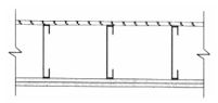
| Assembly Number | Description[2] [3] [4] | Fire-Resistance Rating[5] [6] [7] [8] | Typical Sound Transmission Class[5] [6] [7] [9] [10] [11] (STC) | Typical Impact Insulation Class[5] [9] [12] (IIC) |
|---|---|---|---|---|
| F40a | F40 with
| 1 h | 34 | 31 |
| F40b | F40 with
| 45 min | 35 | 31 |
| F40c | F40 with
| 45 min | 36 | 34 |
| F40d | F40 with
| 45 min | 37 | 34 |
| F40e | F40 with
| 1 h | 32 | 30 |
| F40f | F40 with
| 45 min | 33 | 30 |
| F40g | F40 with
| 45 min | 34 | 33 |
| F40h | F40 with
| 45 min | 35 | 33 |
| F40i | F40 with
| N/A | 31 | 30 |
| F40j | F40 with
| N/A | 33 | 33 |
| Column 2 | 3 | 4 | 5 | 6 |
Type of Assembly
Cold Formed Steel Floor Joists[27]
Assembly Number: F41
- subfloor of 15.5 mm plywood, OSB or waferboard, or 17 mm tongue and groove lumber
- on steel joists spaced not more than 610 mm o.c.
- with or without absorptive material in cavity
- steel furring channels spaced 406 mm or 610 mm o.c.
- 1 layer of gypsum board on ceiling side
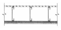
| Assembly Number | Description[2] [3] [4] | Fire-Resistance Rating[5] [6] [7] [8] | Typical Sound Transmission Class[5] [6] [7] [9] [10] [11] (STC) | Typical Impact Insulation Class[5] [9] [12] (IIC) |
|---|---|---|---|---|
| F41a | F41 with
| N/A | 34 | 27 |
| F41b | F41 with
| N/A | 37 | 30 |
| F41c | F41 with
| 30 min [45 min][25] | 37 | 30 |
| F41d | F41 with
| 30 min | 40 | 33 |
| F41e | F41 with
| N/A | 33 | 26 |
| F41f | F41 with
| N/A | 35 | 29 |
| F41g | F41 with
| 30 min [45 min][25] | 36 | 29 |
| F41h | F41 with
| 30 min | 38 | 32 |
| F41i | F41 with
| < 30 min | 32 | 25 |
| F41j | F41 with
| < 30 min | 35 | 28 |
| F41k | F41 with
| < 30 min | 35 | 28 |
| F41l | F41 with
| < 30 min | 38 | 31 |
| Column 2 | 3 | 4 | 5 | 6 |
Type of Assembly
Cold Formed Steel Floor Joists[27]
Assembly Number: F42
- subfloor of 15.5 mm plywood, OSB or waferboard, or 17 mm tongue and groove lumber
- on steel joists spaced not more than 610 mm o.c.
- with or without absorptive material in cavity
- steel furring channels spaced 406 mm or 610 mm o.c.
- 2 layers of gypsum board on ceiling side
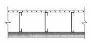
| Assembly Number | Description[2] [3] [4] | Fire-Resistance Rating[5] [6] [7] [8] | Typical Sound Transmission Class[5] [6] [7] [9] [10] [11] (STC) | Typical Impact Insulation Class[5] [9] [12] (IIC) |
|---|---|---|---|---|
| F42a | F42 with
| 1 h | 39 | 32 |
| F42b | F42 with
| 45 min | 42 | 34 |
| F42c | F42 with
| 45 min | 43 | 34 |
| F42d | F42 with
| 1 h | 42 | 35 |
| F42e | F42 with
| 45 min [1 h][28] | 45 | 37 |
| F42f | F42 with
| 45 min [1 h][15] | 46 | 37 |
| F42g | F42 with
| 1 h | 38 | 30 |
| F42h | F42 with
| 45 min | 40 | 33 |
| F42i | F42 with
| 45 min | 41 | 33 |
| F42j | F42 with
| 1 h | 41 | 33 |
| F42k | F42 with
| 45 min [1 h][28] | 43 | 36 |
| F42l | F42 with
| 45 min [1 h][15] | 44 | 36 |
| F42m | F42 with
| N/A | 37 | 30 |
| F42n | F42 with
| N/A | 39 | 33 |
| F42o | F42 with
| N/A | 40 | 33 |
| F42p | F42 with
| N/A | 42 | 36 |
| Column 2 | 3 | 4 | 5 | 6 |
Type of Assembly
Cold Formed Steel Floor Joists[27]
Assembly Number: F43
- subfloor of 15.5 mm plywood, OSB or waferboard, or 17 mm tongue and groove lumber
- on steel joists spaced not more than 610 mm o.c.
- with or without absorptive material in cavity
- 1 layer of gypsum board attached directly to joists on ceiling side
- resilient metal channels spaced 406 mm or 610 mm o.c. attached to joists through the gypsum board
- 1 layer of gypsum board attached to resilient metal channels
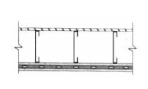
| Assembly Number | Description[2] [3] [4] | Fire-Resistance Rating[5] [6] [7] [8] | Typical Sound Transmission Class[5] [6] [7] [9] [10] [11] (STC) | Typical Impact Insulation Class[5] [9] [12] (IIC) |
|---|---|---|---|---|
| F43a | F43 with
| 1 h | 35 | 37 |
| F43b | F43 with
| 1 h | 37 | 30 |
| F43c | F43 with
| 1 h | 35 | 27 |
| F43d | F43 with
| 1 h | 37 | 30 |
| F43e | F43 with
| N/A | 32 | 26 |
| F43f | F43 with
| N/A | 35 | 28 |
| Column 2 | 3 | 4 | 5 | 6 |
Type of Assembly
Cold Formed Steel Floor Joists[27]
Assembly Number: F44
- subfloor of 15.5 mm plywood, OSB or waferboard, or 17 mm tongue and groove lumber
- on steel joists spaced not more than 610 mm o.c.
- with or without absorptive material in cavity
- resilient metal channels spaced 406 mm or 610 mm o.c.
- 1 layer of gypsum board on ceiling side
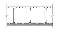
| Assembly Number | Description[2] [3] [4] | Fire-Resistance Rating[5] [6] [7] [8] | Typical Sound Transmission Class[5] [6] [7] [9] [10] [11] (STC) | Typical Impact Insulation Class[5] [9] [12] (IIC) |
|---|---|---|---|---|
| F44a | F44 with
| N/A | 40 | 33 |
| F44b | F44 with
| N/A | 43 | 36 |
| F44c | F44 with
| 30 min [45 min][25] | 47 | 41 |
| F44d | F44 with
| 30 min | 50 | 44 |
| F44e | F44 with
| N/A | 39 | 32 |
| F44f | F44 with
| N/A | 41 | 35 |
| F44g | F44 with
| 30 min [45 min][25] | 46 | 40 |
| F44h | F44 with
| 30 min | 48 | 43 |
| F44i | F44 with
| < 30 min | 38 | 31 |
| F44j | F44 with
| < 30 min | 41 | 34 |
| F44k | F44 with
| < 30 min | 45 | 39 |
| F44l | F44 with
| < 30 min | 48 | 42 |
| Column 2 | 3 | 4 | 5 | 6 |
Type of Assembly
Cold Formed Steel Floor Joists[27]
Assembly Number: F45
- subfloor of 15.5 mm plywood, OSB or waferboard, or 17 mm tongue and groove lumber
- on steel joists spaced not more than 610 mm o.c.
- with or without absorptive material in cavity
- resilient metal channels spaced 406 mm or 610 mm o.c.
- 2 layers of gypsum board on ceiling side
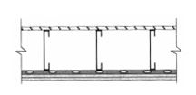
| Assembly Number | Description[2] [3] [4] | Fire-Resistance Rating[5] [6] [7] [8] | Typical Sound Transmission Class[5] [6] [7] [9] [10] [11] (STC) | Typical Impact Insulation Class[5] [9] [12] (IIC) |
|---|---|---|---|---|
| F45a | F45 with
| 1 h | 45 | 38 |
| F45b | F45 with
| 45 min | 48 | 40 |
| F45c | F45 with
| 45 min | 49 | 40 |
| F45d | F45 with
| 1 h | 52 | 46 |
| F45e | F45 with
| 45 min [1 h][28] | 55 | 48 |
| F45f | F45 with
| 45 min [1 h][15] | 56 | 48 |
| F45g | F45 with
| 1 h | 44 | 36 |
| F45h | F45 with
| 45 min | 46 | 39 |
| F45i | F45 with
| 45 min | 47 | 39 |
| F45j | F45 with
| 1 h | 51 | 44 |
| F45k | F45 with
| 45 min [1 h][28] | 53 | 47 |
| F45l | F45 with
| 45 min [1 h][15] | 54 | 47 |
| F45m | F45 with
| N/A | 43 | 36 |
| F45n | F45 with
| N/A | 45 | 39 |
| F45o | F45 with
| N/A | 50 | 44 |
| F45p | F45 with
| N/A | 52 | 47 |
| Column 2 | 3 | 4 | 5 | 6 |
Type of Assembly
Cold Formed Steel Floor Joists[27]
Assembly Number: F46
- one subfloor layer of 11 mm sanded plywood, or OSB or waferboard
- one subfloor layer of 15.5 mm plywood, OSB or waferboard, or 17 mm tongue and groove lumber
- on steel joists spaced not more than 610 mm o.c.
- with or without absorptive material in cavity
- resilient metal channels spaced 406 mm or 610 mm o.c.
- 1 layer of gypsum board on ceiling side
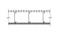
| Assembly Number | Description[2] [3] [4] | Fire-Resistance Rating[5] [6] [7] [8] | Typical Sound Transmission Class[5] [6] [7] [9] [10] [11] (STC) | Typical Impact Insulation Class[5] [9] [12] (IIC) |
|---|---|---|---|---|
| F46a | F46 with
| N/A | 43 | 34 |
| F46b | F46 with
| N/A | 46 | 37 |
| F46c | F46 with
| N/A | 50 | 42 |
| F46d | F46 with
| N/A | 53 | 45 |
| F46e | F46 with
| N/A | 42 | 33 |
| F46f | F46 with
| N/A | 44 | 36 |
| F46g | F46 with
| N/A | 49 | 41 |
| F46h | F46 with
| N/A | 51 | 44 |
| F46i | F46 with
| N/A | 41 | 33 |
| F46j | F46 with
| N/A | 44 | 36 |
| F46k | F46 with
| N/A | 48 | 41 |
| F46l | F46 with
| N/A | 51 | 44 |
| Column 2 | 3 | 4 | 5 | 6 |
Type of Assembly
Cold Formed Steel Floor Joists[27]
Assembly Number: F47
- one subfloor layer of 15.5 mm plywood or OSB or waferboard
- one subfloor layer of 15.5 mm plywood, OSB or waferboard, or 17 mm tongue and groove lumber
- on steel joists spaced not more than 406 mm o.c.
- with or without absorptive material in cavity
- resilient metal channels spaced 406 mm or 610 mm o.c.
- 1 layer of gypsum board on ceiling side
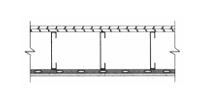
| Assembly Number | Description[2] [3] [4] | Fire-Resistance Rating[5] [6] [7] [8] | Typical Sound Transmission Class[5] [6] [7] [9] [10] [11] (STC) | Typical Impact Insulation Class[5] [9] [12] (IIC) |
|---|---|---|---|---|
| F47a | F47 with
| 30 min | 45 | 35 |
| F47b | F47 with
| 30 min | 47 | 38 |
| F47c | F47 with
| 30 min [45 min][18] [1 h][28] | 51 | 45 |
| F47d | F47 with
| [30 min][18] [45 min][28] | 53 | 47 |
| F47e | F47 with
| 30 min | 43 | 44 |
| F47f | F47 with
| N/A | 45 | 47 |
| F47g | F47 with
| [30 min][18] [45 min][28] | 50 | 43 |
| F47h | F47 with
| N/A | 52 | 46 |
| Column 2 | 3 | 4 | 5 | 6 |
Type of Assembly
Cold Formed Steel Floor Joists[27]
Assembly Number: F48
- one subfloor layer of 11 mm sanded plywood, or OSB or waferboard
- one subfloor layer of 15.5 mm plywood, OSB or waferboard, or 17 mm tongue and groove lumber
- on steel joists spaced not more than 610 mm o.c.
- with or without absorptive material in cavity
- resilient metal channels spaced 406 mm or 610 mm o.c.
- 2 layers of gypsum board on ceiling side
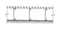
| Assembly Number | Description[2] [3] [4] | Fire-Resistance Rating[5] [6] [7] [8] | Typical Sound Transmission Class[5] [6] [7] [9] [10] [11] (STC) | Typical Impact Insulation Class[5] [9] [12] (IIC) |
|---|---|---|---|---|
| F48a | F48 with
| 1 h | 48 | 39 |
| F48b | F48 with
| 1 h | 50 | 42 |
| F48c | F48 with
| 1 h | 56 | 47 |
| F48d | F48 with
| 1 h | 57 | 50 |
| F48e | F48 with
| 1 h | 47 | 38 |
| F48f | F48 with
| N/A | 49 | 40 |
| F48g | F48 with
| 1 h | 54 | 46 |
| F48h | F48 with
| N/A | 56 | 48 |
| F48i | F48 with
| N/A | 46 | 37 |
| F48j | F48 with
| N/A | 48 | 40 |
| F48k | F48 with
| N/A | 53 | 45 |
| F48l | F48 with
| N/A | 55 | 48 |
| Column 2 | 3 | 4 | 5 | 6 |
Type of Assembly
Cold Formed Steel Floor Joists[27]
Assembly Number: F49
- 25 mm gypsum-concrete topping (at least 44 kg/m2)
- subfloor of 15.5 mm plywood, OSB or waferboard, or 17 mm tongue and groove lumber
- on steel joists spaced not more than 610 mm o.c.
- with or without absorptive material in cavity
- 1 layer of gypsum board on ceiling side
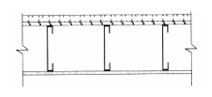
| Assembly Number | Description[2] [3] [4] | Fire-Resistance Rating[5] [6] [7] [8] | Typical Sound Transmission Class[5] [6] [7] [9] [10] [11] (STC) | Typical Impact Insulation Class[5] [9] [12] (IIC) |
|---|---|---|---|---|
| F49a | F49 with
| N/A | 40 | 13 |
| F49b | F49 with
| N/A | 42 | 16 |
| F49c | F49 with
| N/A | 39 | 12 |
| F49d | F49 with
| N/A | 41 | 15 |
| F49e | F49 with
| N/A | 38 | 12 |
| F49f | F49 with
| N/A | 40 | 15 |
| Column 2 | 3 | 4 | 5 | 6 |
Type of Assembly
Cold Formed Steel Floor Joists[27]
Assembly Number: F50
- 25 mm gypsum-concrete topping (at least 44 kg/m2)
- subfloor of 15.5 mm plywood, OSB or waferboard, or 17 mm tongue and groove lumber
- on steel joists spaced not more than 610 mm o.c.
- with or without absorptive material in cavity
- 2 layers of gypsum board on ceiling side
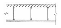
| Assembly Number | Description[2] [3] [4] | Fire-Resistance Rating[5] [6] [7] [8] | Typical Sound Transmission Class[5] [6] [7] [9] [10] [11] (STC) | Typical Impact Insulation Class[5] [9] [12] (IIC) |
|---|---|---|---|---|
| F50a | F50 with
| N/A | 45 | 16 |
| F50b | F50 with
| N/A | 47 | 19 |
| F50c | F50 with
| N/A | 44 | 15 |
| F50d | F50 with
| N/A | 46 | 18 |
| F50e | F50 with
| N/A | 43 | 14 |
| F50f | F50 with
| N/A | 45 | 17 |
| Column 2 | 3 | 4 | 5 | 6 |
Type of Assembly
Cold Formed Steel Floor Joists[27]
Assembly Number: F51
- 25 mm gypsum-concrete topping (at least 44 kg/m2)
- subfloor of 15.5 mm plywood, OSB or waferboard, or 17 mm tongue and groove lumber
- on steel joists spaced not more than 610 mm o.c.
- with or without absorptive material in cavity
- resilient metal channels spaced 406 mm or 610 mm o.c.
- 1 layer of gypsum board on ceiling side
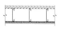
| Assembly Number | Description[2] [3] [4] | Fire-Resistance Rating[5] [6] [7] [8] | Typical Sound Transmission Class[5] [6] [7] [9] [10] [11] (STC) | Typical Impact Insulation Class[5] [9] [12] (IIC) |
|---|---|---|---|---|
| F51a | F51 with
| N/A | 52 | 22 |
| F51b | F51 with
| N/A | 54 | 22 |
| F51c | F51 with
| N/A | 59 | 30 |
| F51d | F51 with
| N/A | 61 | 30 |
| F51e | F51 with
| N/A | 51 | 21 |
| F51f | F51 with
| N/A | 53 | 21 |
| F51g | F51 with
| N/A | 58 | 29 |
| F51h | F51 with
| N/A | 60 | 29 |
| F51i | F51 with
| N/A | 50 | 21 |
| F51j | F51 with
| N/A | 52 | 21 |
| F51k | F51 with
| N/A | 57 | 29 |
| F51l | F51 with
| N/A | 59 | 29 |
| Column 2 | 3 | 4 | 5 | 6 |
Type of Assembly
Cold Formed Steel Floor Joists[27]
Assembly Number: F52
- 25 mm gypsum-concrete topping (at least 44 kg/m2)
- subfloor of 15.5 mm plywood, OSB or waferboard, or 17 mm tongue and groove lumber
- on steel joists spaced not more than 610 mm o.c.
- with or without absorptive material in cavity
- resilient metal channels spaced 406 mm or 610 mm o.c.
- 2 layers of gypsum board on ceiling side
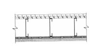
| Assembly Number | Description[2] [3] [4] | Fire-Resistance Rating[5] [6] [7] [8] | Typical Sound Transmission Class[5] [6] [7] [9] [10] [11] (STC) | Typical Impact Insulation Class[5] [9] [12] (IIC) |
|---|---|---|---|---|
| F52a | F52 with
| 1 h | 57 | 25 |
| F52b | F52 with
| 1 h | 59 | 25 |
| F52c | F52 with
| 1 h | 64 | 33 |
| F52d | F52 with
| 45 min [1 h][25] | 66 | 33 |
| F52e | F52 with
| 1 h | 55 | 24 |
| F52f | F52 with
| 1 h | 58 | 24 |
| F52g | F52 with
| 1 h | 62 | 32 |
| F52h | F52 with
| 45 min [1 h][25] | 65 | 32 |
| F52i | F52 with
| N/A | 55 | 23 |
| F52j | F52 with
| N/A | 57 | 23 |
| F52k | F52 with
| N/A | 62 | 31 |
| F52l | F52 with
| N/A | 64 | 31 |
| Column 2 | 3 | 4 | 5 | 6 |
Type of Assembly
Cold Formed Steel Floor Joists[27]
Assembly Number: F53
- 38 mm concrete topping (at least 70 kg/m2)
- subfloor of 12.5 mm plywood, OSB or waferboard, or 17 mm tongue and groove lumber
- on steel joists spaced not more than 610 mm o.c.
- 1 layer of gypsum board on ceiling side
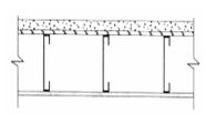
| Assembly Number | Description[2] [3] [4] | Fire-Resistance Rating[5] [6] [7] [8] | Typical Sound Transmission Class[5] [6] [7] [9] [10] [11] (STC) | Typical Impact Insulation Class[5] [9] [12] (IIC) |
|---|---|---|---|---|
| F53a | F53 with
| N/A | 44 | 22 |
| F53b | F53 with
| N/A | 46 | 25 |
| F53c | F53 with
| N/A | 42 | 21 |
| F53d | F53 with
| N/A | 44 | 24 |
| F53e | F53 with
| N/A | 42 | 21 |
| F53f | F53 with
| N/A | 44 | 24 |
| Column 2 | 3 | 4 | 5 | 6 |
Type of Assembly
Cold Formed Steel Floor Joists[27]
Assembly Number: F54
- 38 mm concrete topping (at least 70 kg/m2)
- subfloor of 15.5 mm plywood, OSB or waferboard, or 17 mm tongue and groove lumber
- on steel joists spaced not more than 610 mm o.c.
- 2 layers of gypsum board on ceiling side
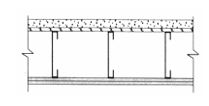
| Assembly Number | Description[2] [3] [4] | Fire-Resistance Rating[5] [6] [7] [8] | Typical Sound Transmission Class[5] [6] [7] [9] [10] [11] (STC) | Typical Impact Insulation Class[5] [9] [12] (IIC) |
|---|---|---|---|---|
| F54a | F54 with
| N/A | 48 | 24 |
| F54b | F54 with
| N/A | 50 | 27 |
| F54c | F54 with
| N/A | 47 | 23 |
| F54d | F54 with
| N/A | 49 | 26 |
| F54e | F54 with
| N/A | 47 | 23 |
| F54f | F54 with
| N/A | 49 | 26 |
| Column 2 | 3 | 4 | 5 | 6 |
Type of Assembly
Cold Formed Steel Floor Joists[27]
Assembly Number: F55
- 38 mm concrete topping (at least 70 kg/m2)
- subfloor of 15.5 mm plywood, OSB or waferboard, or 17 mm tongue and groove lumber
- on steel joists spaced not more than 610 mm o.c.
- with or without absorptive material in cavity
- resilient metal channels spaced 406 mm or 610 mm o.c.
- 1 layer of gypsum board on ceiling side
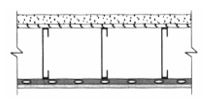
| Assembly Number | Description[2] [3] [4] | Fire-Resistance Rating[5] [6] [7] [8] | Typical Sound Transmission Class[5] [6] [7] [9] [10] [11] (STC) | Typical Impact Insulation Class[5] [9] [12] (IIC) |
|---|---|---|---|---|
| F55a | F55 with
| N/A | 56 | 31 |
| F55b | F55 with
| N/A | 58 | 31 |
| F55c | F55 with
| N/A | 63 | 39 |
| F55d | F55 with
| N/A | 65 | 39 |
| F55e | F55 with
| N/A | 54 | 30 |
| F55f | F55 with
| N/A | 56 | 30 |
| F55g | F55 with
| N/A | 61 | 38 |
| F55h | F55 with
| N/A | 63 | 38 |
| F55i | F55 with
| N/A | 54 | 30 |
| F55j | F55 with
| N/A | 56 | 30 |
| F55k | F55 with
| N/A | 61 | 38 |
| F55l | F55 with
| N/A | 63 | 38 |
| Column 2 | 3 | 4 | 5 | 6 |
Type of Assembly
Cold Formed Steel Floor Joists[27]
Assembly Number: F56
- 38 mm concrete topping (at least 70 kg/m2)
- subfloor of 15.5 mm plywood, OSB or waferboard, or 17 mm tongue and groove lumber
- on steel joists spaced not more than 610 mm o.c.
- with or without absorptive material in cavity
- resilient metal channels spaced 406 mm or 610 mm o.c.
- 2 layers of gypsum board on ceiling side
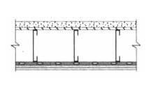
| Assembly Number | Description[2] [3] [4] | Fire-Resistance Rating[5] [6] [7] [8] | Typical Sound Transmission Class[5] [6] [7] [9] [10] [11] (STC) | Typical Impact Insulation Class[5] [9] [12] (IIC) |
|---|---|---|---|---|
| F56a | F56 with
| 1 h | 60 | 33 |
| F56b | F56 with
| 1 h | 62 | 33 |
| F56c | F56 with
| 1 h | 67 | 41 |
| F56d | F56 with
| 45 min [1 h][25] | 69 | 41 |
| F56e | F56 with
| 1 h | 59 | 32 |
| F56f | F56 with
| 1 h | 61 | 32 |
| F56g | F56 with
| 1 h | 66 | 40 |
| F56h | F56 with
| 45 min [1 h][25] | 68 | 40 |
| F56i | F56 with
| N/A | 58 | 32 |
| F56j | F56 with
| N/A | 61 | 32 |
| F56k | F56 with
| N/A | 65 | 40 |
| F56l | F56 with
| N/A | 68 | 40 |
| Column 2 | 3 | 4 | 5 | 6 |
Type of Assembly
Cold Formed Steel Floor Joists[27]
Assembly Number: F57
- 50 mm concrete
- 0.46 mm metal pan with a 19 mm rib
- on steel joists spaced not more than 610 mm o.c.
- 1 layer of gypsum board on ceiling side
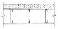
| Assembly Number | Description[2] [3] [4] | Fire-Resistance Rating[5] [6] [7] [8] | Typical Sound Transmission Class[5] [6] [7] [9] [10] [11] (STC) | Typical Impact Insulation Class[5] [9] [12] (IIC) |
|---|---|---|---|---|
| F57a | F57 with
| N/A | 45 | 26 |
| F57b | F57 with
| N/A | 47 | 29 |
| F57c | F57 with
| N/A | 44 | 25 |
| F57d | F57 with
| N/A | 46 | 28 |
| F57e | F57 with
| N/A | 43 | 25 |
| F57f | F57 with
| N/A | 45 | 28 |
| Column 2 | 3 | 4 | 5 | 6 |
Type of Assembly
Cold Formed Steel Floor Joists[27]
Assembly Number: F58
- 50 mm concrete
- 0.38 mm metal pan with a 16 mm rib
- on steel joists spaced not more than 610 mm o.c.
- 2 layers of gypsum board on ceiling side
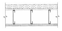
| Assembly Number | Description[2] [3] [4] | Fire-Resistance Rating[5] [6] [7] [8] | Typical Sound Transmission Class[5] [6] [7] [9] [10] [11] (STC) | Typical Impact Insulation Class[5] [9] [12] (IIC) |
|---|---|---|---|---|
| F58a | F58 with
| N/A | 50 | 27 |
| F58b | F58 with
| N/A | 52 | 30 |
| F58c | F58 with
| N/A | 48 | 27 |
| F58d | F58 with
| N/A | 50 | 30 |
| F58e | F58 with
| N/A | 48 | 27 |
| F58f | F58 with
| N/A | 50 | 30 |
| Column 2 | 3 | 4 | 5 | 6 |
Type of Assembly
Cold Formed Steel Floor Joists[27]
Assembly Number: F59
- 50 mm concrete
- 0.38 mm metal pan with a 16 mm rib
- on steel joists spaced not more than 610 mm o.c.
- with or without absorptive material in cavity
- resilient metal channels spaced 406 mm or 610 mm o.c.
- 1 layer of gypsum board on ceiling side
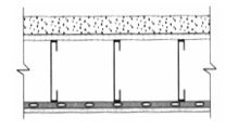
| Assembly Number | Description[2] [3] [4] | Fire-Resistance Rating[5] [6] [7] [8] | Typical Sound Transmission Class[5] [6] [7] [9] [10] [11] (STC) | Typical Impact Insulation Class[5] [9] [12] (IIC) |
|---|---|---|---|---|
| F59a | F59 with
| N/A | 57 | 35 |
| F59b | F59 with
| N/A | 59 | 35 |
| F59c | F59 with
| N/A | 64 | 43 |
| F59d | F59 with
| N/A | 66 | 43 |
| F59e | F59 with
| N/A | 56 | 34 |
| F59f | F59 with
| N/A | 56 | 34 |
| F59g | F59 with
| N/A | 63 | 42 |
| F59h | F59 with
| N/A | 65 | 42 |
| F59i | F59 with
| N/A | 55 | 34 |
| F59j | F59 with
| N/A | 57 | 34 |
| F59k | F59 with
| N/A | 62 | 42 |
| F59l | F59 with
| N/A | 64 | 42 |
| Column 2 | 3 | 4 | 5 | 6 |
Type of Assembly
Cold Formed Steel Floor Joists[27]
Assembly Number: F60
- 50 mm concrete
- 0.46 mm metal pan with a 19 mm rib
- on steel joists spaced not more than 610 mm o.c.
- with or without absorptive material in cavity
- resilient metal channels spaced 406 mm or 610 mm o.c.
- 2 layers of gypsum board on ceiling side
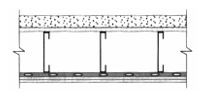
| Assembly Number | Description[2] [3] [4] | Fire-Resistance Rating[5] [6] [7] [8] | Typical Sound Transmission Class[5] [6] [7] [9] [10] [11] (STC) | Typical Impact Insulation Class[5] [9] [12] (IIC) |
|---|---|---|---|---|
| F60a | F60 with
| 1 h | 62 | 36 |
| F60b | F60 with
| 1 h | 64 | 36 |
| F60c | F60 with
| 1 h | 69 | 44 |
| F60d | F60 with
| 45 min [1 h][25] | 71 | 44 |
| F60e | F60 with
| 1 h | 60 | 36 |
| F60f | F60 with
| 1 h | 62 | 36 |
| F60g | F60 with
| 1 h | 67 | 44 |
| F60h | F60 with
| 45 min [1 h][25] | 69 | 44 |
| F60i | F60 with
| N/A | 60 | 36 |
| F60j | F60 with
| N/A | 62 | 36 |
| F60k | F60 with
| N/A | 67 | 44 |
| F60l | F60 with
| N/A | 69 | 44 |
| Column 2 | 3 | 4 | 5 | 6 |
Type of Assembly
Cold Formed Steel Floor Joists[27]
Assembly Number: F61
- 50 mm concrete
- 0.38 mm metal pan with a 16 mm rib
- on steel joists spaced not more than 610 mm o.c.
- with or without absorptive material in cavity
- resilient metal channels spaced 406 mm or 610 mm o.c.
- 2 layers of gypsum board on ceiling side
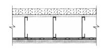
| Assembly Number | Description[2] [3] [4] | Fire-Resistance Rating[5] [6] [7] [8] | Typical Sound Transmission Class[5] [6] [7] [9] [10] [11] (STC) | Typical Impact Insulation Class[5] [9] [12] (IIC) |
|---|---|---|---|---|
| F61a | F61 with
| 1 h | 62 | 32 |
| F61b | F61 with
| 1 h | 64 | 32 |
| F61c | F61 with
| N/A | 65 | 29 |
| F61d | F61 with
| 1 h | 68 | 37 |
| F61e | F61 with
| 1 h | 66 | 34 |
| F61f | F61 with
| N/A | 71 | 34 |
| F61g | F61 with
| 1 h | 62 | 32 |
| F61h | F61 with
| 1 h | 64 | 32 |
| F61i | F61 with
| N/A | 64 | 28 |
| F61j | F61 with
| 1 h | 68 | 36 |
| F61k | F61 with
| 1 h | 64 | 32 |
| F61l | F61 with
| N/A | 70 | 34 |
| Column 2 | 3 | 4 | 5 | 6 |
Roofs
Type of Assembly
Wood Roof Trusses
Assembly Number: R1
- wood roof trusses spaced not more than 610 mm o.c.
- 1 layer 15.9 mm Type X gypsum board
Roofs - Rating Provided by Membrane Only
Assembly Number: M1
- supporting members spaced not more than 610 mm o.c.
- 1 layer 15.9 mm Type X gypsum board
Assembly Number: M2
- supporting members spaced not more than 610 mm o.c.
- 2 layers 15.9 mm Type X gypsum board
Notes to Table 2:
- Reserved.
- For assemblies with a ceiling consisting of a single layer of gypsum board on resilient metal channels to obtain the listed ratings, the resilient metal channel arrangement at the gypsum board butt end joints should be as shown in Figure 1.
- For assemblies with a ceiling consisting of 2 layers of gypsum board on resilient metal channels to obtain the listed ratings, the fastener and resilient metal channel arrangement at the gypsum board butt end joints should be as shown in Figure 2.
The fire-resistance rating and sound transmission class values given are for a minimum thickness of subfloor or deck as shown.
Minimum subfloor thickness required is determined by structural member spacing (see Table 9.23.15.5.A. of Division B of the Building Code). Thicker subflooring or decking is also acceptable.
Sound absorptive material includes
- fibre processed from rock, slag or glass, and
- loose-fill or spray-applied cellulose fibre.
To obtain the listed sound transmission class rating, the nominal insulation thickness is 150 mm for rock, slag, or glass fibres or loose-fill cellulose fibre, and 90 mm for spray-applied cellulose fibre, unless otherwise specified. Absorptive material will affect the sound transmission class by approximately adding or subtracting 1 per 50 mm change of thickness. However, no additional sound transmission class value is achieved by adding a greater thickness of insulation than the depth of the assembly.
- The fire-resistance rating and sound transmission class values are based on the spacing of ceiling supports as noted. [See also Table Note (10)]. A narrower spacing will be detrimental to the sound transmission class rating, but not to the fire-resistance rating.
To obtain the listed rating, fastener type, spacing and penetration depth for the attachment of gypsum board must conform to Subsection 9.29.5. of Division B of the Building Code, and
- fastener distance to board edges and butt ends shall be no less than 38 mm, except for fasteners on the butt ends of the base layer in ceilings with two layers (see Figure 2),
- fasteners are spaced not more than 305 mm o.c.,
- fasteners must consist of nails or screws when attaching gypsum board to wood members, and
- fasteners must consist of screws when attaching gypsum board to cold-formed steel channels or resilient metal channels.
For wood- and steel-framed assemblies, if fasteners are spaced less than 300 mm o.c., subtract 1 from the sound transmission class value; if fasteners are spaced less than 200 mm o.c., subtract 2 from the sound transmission class value. Narrower fastener spacing is not detrimental to the fire-resistance rating.
- See Sentence 1.2.1.(2) in MMAH Supplementary Standard SB-2, "Fire Performance Ratings" for the significance of fire-resistance ratings.
- The sound transmission class values given in the Table are for the minimum depth of structural member noted in the description and applicable Table notes. To obtain sound transmission class values for structural members deeper than that minimum, add 1 to the sound transmission class value in the Table for each 170 mm increase in structural member depth.
- The sound transmission class values given in the Table are for structural member spacing of 305 mm o.c., unless otherwise noted in the description and applicable Table notes. To obtain sound transmission class values for assemblies with structural members spaced more than 500 mm o.c., add 1 to the sound transmission class value in the Table.
- Assemblies with sound transmission class ratings of 50 or more require methods to minimize airborne sound transmission at electrical boxes and other openings, and at wall/wall and wall/floor junctions, except at junctions constructed of concrete-to-concrete, concrete-to-masonry, or masonry-to-masonry where the intersecting joint along the junction is cast or mortared.
- The impact insulation class values given are for floor assemblies tested with no finished flooring.
- Wood floor joists are:
- wood joists with a minimum member size of 38 mm (width) x 235 mm (depth), except as otherwise noted [See Table Note (16)], or
- wood I-joists with a minimum flange size of 38 mm × 38 mm, a minimum OSB or plywood web thickness of 9.5 mm, and a minimum joist depth of 241 mm.
- Except where assemblies with wood I-joists are tested according to CAN/ULC-S101-14, "Fire Endurance Tests of Building Construction and Materials", the fire-resistance rating values apply only to I-joists that have been fabricated with a phenolic-based structural wood adhesive complying with CSA O112.10-08, "Evaluation of Adhesives for Structural Wood Products (Limited Moisture Exposure)". For I-joists with flanges made of laminated veneer lumber (LVL), the fire-resistance rating values apply only where the adhesive used in the LVL fabrication is a phenolic-based structural wood adhesive complying with CSA O112.9-10, "Evaluation of Adhesives for Structural Wood Products (Exterior Exposure)".
- The fire-resistance rating value within square brackets is achieved only where absorptive material includes spray-applied cellulose fibre with
- adhesive that is capable of providing a minimum cohesive/adhesive bond strength per unit area of 5 times the weight of the material under the test plate when tested in accordance with ASTM E736/E736 M-17, "Cohesion/Adhesion of Sprayed Fire-Resistive Materials Applied to Structural Members",
- a minimum density of 35 kg/m3, and
- a minimum thickness of 90 mm on the underside of the subfloor or deck, of 90 mm on the sides of the structural members, and for cold-formed steel joists, of 13 mm on the underside of the bottom flange other than at resilient metal channel locations.
- The fire-resistance rating value within square brackets only applies to assemblies with solid wood joists and is achieved only where absorptive material includes:
- fibre processed from rock or slag with a minimum thickness of 90 mm and a minimum surface area mass of 2.8 kg/m2, or
- spray-applied cellulose fibre with a minimum density of 50 kg/m³ and a minimum depth of 90 mm on the underside of the subfloor and of 90 mm on the sides of the floor joists.
- The fire-resistance rating, sound transmission class and impact insulation class values given are also applicable to assemblies with 38 mm (width) x 184 mm (depth) solid wood joists.
- The fire-resistance rating value within square brackets is achieved only where absorptive material includes:
- fibre processed from rock or slag with a minimum thickness of 90 mm and a minimum surface area mass of 2.8 kg/m2, or
- spray-applied cellulose fibre with a minimum density of 50 kg/m3 and a minimum depth of 90 mm on the underside of the subfloor and of 90 mm on the webs or the sides of the structural members.
- The fire-resistance rating, sound transmission class and impact insulation class values within the square brackets only apply to assemblies with solid wood joists and are achieved only where absorptive material includes dry-blown cellulose fibre with a minimum density of 40 kg/m³ filling the entire cavity; the cellulose fibre is supported on zinc-coated (galvanized) steel poultry fence fabric conforming to ASTM A390-06, "Zinc-Coated (Galvanized) Steel Poultry Fence Fabric (Hexagonal and Straight Line)" which has 25 mm wide hexagonal mesh openings and 0.81 mm thick (20-gauge) wire and is attached to wood joists with metal staples having legs that are 50 mm long.
- The fire-resistance rating and sound transmission class values are achieved only where absorptive material includes:
- fibre processed from rock or slag that fills the joist cavity and has a minimum surface area mass of 2.8 kg/m², and for structural members at least 270 mm in depth, the fibre includes three layers each of which has a minimum thickness of 90 mm, or
- dry-blown cellulose fibre with a minimum density of 40 kg/m³ filling the entire cavity; the cellulose fibre is supported on zinc-coated (galvanized) steel poultry fence fabric conforming to ASTM A390-06, "Zinc-Coated (Galvanized) Steel Poultry Fence Fabric (Hexagonal and Straight Line)" which has 25 mm wide hexagonal mesh openings and 0.81 mm thick (20-gauge) wire and is attached to wood joists or wood I-joists with metal staples having legs that are 50 mm or 30 mm long, respectively.
- The fire-resistance rating value only applies to assemblies with wood I-joists with flanges with a minimum thickness of 38 mm and a minimum width of 63 mm.
- The fire-resistance rating and sound transmission class values are achieved only where absorptive material includes:
- fibre processed from rock or slag that fills the joist cavity and has a minimum surface area mass of 2.8 kg/m², and for structural members at least 270 mm in depth, the fibre includes three layers each of which has a minimum thickness of 90 mm, or
- dry-blown cellulose fibre with a minimum density of 40 kg/m³ filling the entire cavity; the cellulose fibre is supported on zinc-coated (galvanized) steel poultry fence fabric conforming to ASTM A390-06, "Zinc-Coated (Galvanized) Steel Poultry Fence Fabric (Hexagonal and Straight Line)" which has 25 mm wide hexagonal mesh openings and 0.81 mm thick (20-gauge) wire and is attached to wood joists with metal staples having legs that are 50 mm long.
- The fire-resistance rating values given only apply to assemblies with solid wood joists spaced not more than 406 mm o.c. No information is available for assemblies constructed with wood I-joists.
- Wood floor trusses are:
- metal plate-connected wood trusses with wood framing members not less than 38 mm × 64 mm, metal connector plates not less than 1 mm (nominal) thick with teeth not less than 8 mm long, and a minimum truss depth of 305 mm,
- metal web wood trusses with wood chords not less than 38 mm × 64 mm, V-shaped webs made from galvanized steel of 1 mm (nominal) thickness with plate areas having teeth not less than 8 mm long, and a minimum truss depth of 286 mm, or
- fingerjoined wood trusses with glued fingerjoined connections, chord members not less than 38 mm × 64 mm, web members not less than 38 mm × 38 mm and a minimum truss depth of 330 mm, all of which is glued together with an R-14 phenol-resorcinol resin conforming to CSA O112.10-08, "Evaluation of Adhesives for Structural Wood Products (Limited Moisture Exposure)".
- The fire-resistance rating value within square brackets is achieved only where absorptive material includes fibre processed from rock or slag with a minimum thickness of 90 mm and a minimum surface area mass of 2.8 kg/m².
- The fire-resistance rating and sound transmission class values within square brackets are achieved only where absorptive material includes dry-blown cellulose fibre with a minimum density of 40 kg/m³ filling the entire cavity; the cellulose fibre is supported on zinc-coated (galvanized) steel poultry fence fabric conforming to ASTM A390-06, "Zinc-Coated (Galvanized) Steel Poultry Fence Fabric (Hexagonal and Straight Line)" which has 25 mm wide hexagonal mesh openings and 0.81 mm thick (20-gauge) wire and is attached to wood trusses with metal staples having legs that are 38 mm long.
- Cold-formed steel floor joists (C-shaped joists) are members with a minimum size of 41 mm (width) x 203 mm (depth) x 1.22 mm (material thickness).
- The fire-resistance rating value within square brackets is achieved only where absorptive material includes spray-applied cellulose fibre with a minimum density of 50 kg/m³ and a minimum thickness of 90 mm on the underside of the subfloor, of 90 mm on the sides of the cold-formed steel floor joists, and of 13 mm on the underside of the bottom flange other than at resilient metal channel locations.
Figures 1 to 7
Figure 1 Butt Joint Detail of Single Gypsum Board Layer Application
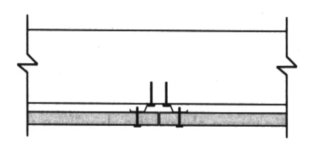
Notes to Figure 1:
- Figure is for illustration purposes only and is not to scale.
- The structural member can be any one of the types described in the Table.
- Adjacent gypsum board butt ends are to be attached to separate resilient channels using regular Type S screws, located a minimum of 38 mm from the butt end.
Figure 2 Butt Joint Detail of Double Gypsum Board Layer Application
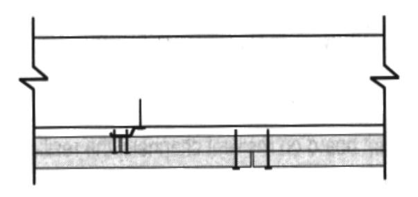
Notes to Figure 2:
- Figure is for illustration purposes only and is not to scale.
- The structural member can be any one of the types described in the Table.
- Base layer butt ends can be attached to a single resilient channel using regular Type S screws.
- Type G screws measuring a minimum of 32 mm in length and located a minimum of 38 mm from the butt end are to be used to fasten the butt ends of the face layer to the base layer.
Figure 3 Example of Steel Furring Channel
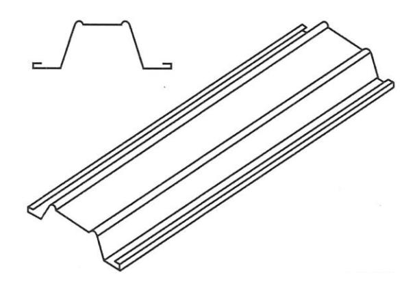
Notes to Figure 3:
- Figure is for illustration purposes only and is not to scale.
Figure 4 Example of Resilient Metal Channel
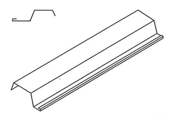
Notes to Figure 4:
- Figure is for illustration purposes only and is not to scale.
Figure 5 Blocking for Lightweight Wood-Frame Walls With a Single or Double Row of Studs
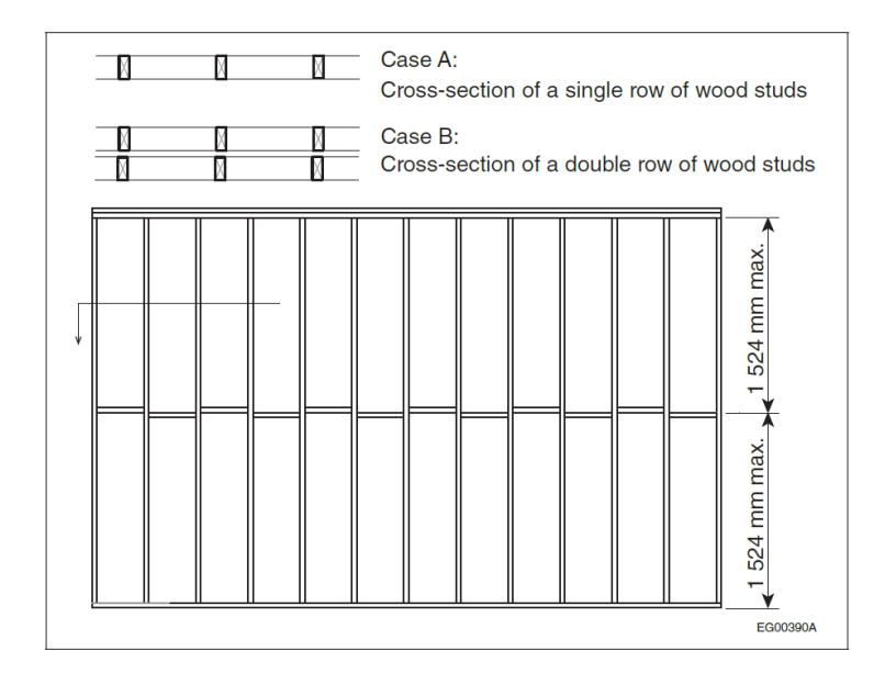
Notes to Figure 5:
- Figure is for illustrative purposes only and is not to scale.
Figure 6 Vertical Application of Exterior Wall Sheathing or Interior Wall Finish With All Joints Backed With Lumber Having the Same Dimensions as the Framing Members
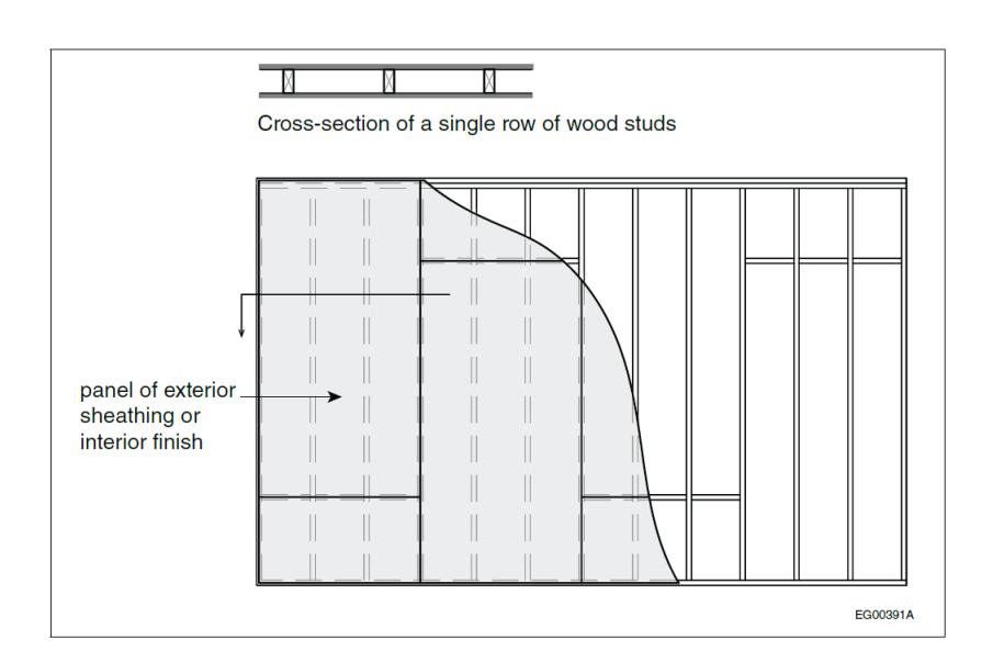
Notes to Figure 6:
- Figure is for illustration purposes only and is not to scale.
Figure 7 Horizontal Application of Exterior Wall Sheathing or Interior Wall Finish With All Joints Backed With Lumber Having the Same Dimensions as the Framing Members
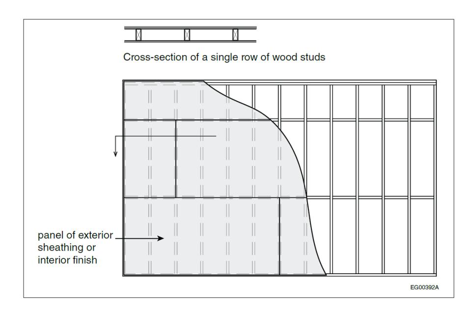
Notes to Figure 7:
- Figure is for illustration purposes only and is not to scale.